Mesa Laboratories DT002 DataTrace RF System (DTENV) User Manual DataTrace DTENV Manual
Mesa Laboratories, Inc. DataTrace RF System (DTENV) DataTrace DTENV Manual
Exhibit 8
1 of 27 pages
DataTrace® RF
(DTENV) Operator’s
Manual
2 of 27 pages
INTRODUCTION
Compliance Information
Any modifications to this product may violate the rules of the Federal Communications
Commission or Industry Canada ICES-003 and make operation of the product unlawful.
This equipment has been tested and found to comply with the limits for a Class B digital
device, pursuant to part 15 of the FCC Rules and Industry Canada ICES-003. These limits
are designed to provide reasonable protection against harmful interference in a residential
installation. This equipment generates, uses, and can radiate radio frequency energy and, if
not installed and used in accordance with the instructions, may cause harmful interference
to radio communications. However, there is no guarantee that interference will not occur in
a particular installation. If this equipment does cause harmful interference to radio or
television reception, which can be determined by turning the equipment off and on, the user
is encouraged to try to correct the interference by one or more of the following measures:
• Reorient or relocate the receiving antenna.
• Increase the separation between the equipment and receiver.
• Connect the equipment into an outlet on a circuit different from that to which the
receiver is connected.
• Consult the dealer or an experienced radio/TV technician for help.
This equipment complies with FCC radiation exposure limits set forth for an uncontrolled
environment. The antenna(s) used for this equipment must be installed to provide a
separation distance of at least 8 inches (20cm) from all persons.
This device complies with Part 15 of the FCC Rules, Industry Canada ICES-003 and RSS-
Gen. Operation is subject to the following two conditions:
1. This device may not cause harmful interference.
2. This device must accept any interference received, including interference that may cause
undesired operation.
3. This device is susceptible to electrostatic discharge (ESD) and surge phenomenon.
The FCC identification number is FCC ID: UUYDT002
The Industry Canada identification number is IC: 6891A-DT002
3 of 27 pages
NOTICE OF COPYRIGHT
1985-2009 MESA LABORATORIES, INC.
All rights reserved. This publication contains proprietary information which is protected by
copyright. No part of this publication may be reproduced, transcribed, stored in a retrieval
system, translated into any language or computer language, or transmitted in any form
whatsoever without the prior written consent of MESA LABORATORIES, INC.
NOTICE OF TRADEMARK
DataTrace TEMP and DataTrace are registered trademarks of MESA LABORATORIES,
INC. DataTrace MICROPACK, DataTrace RF, MICROPACK, MICROPACK III,
MICROPACK RF, MPIII, MP-RF, DataTrace FLATPACK, FLATPACK, LOTEMP AND
HITEMP are trademarks of MESA LABORATORIES, INC.
All other brand names and product names used in this manual are Trademarks, Registered
Trademarks, Service Marks, or Trade Names of their respective holders.
4 of 27 pages
DataTrace® RF SYSTEM
OPERATOR’S MANUAL
Mesa Laboratories, Inc. provides this manual as a customer aid in the use of the DataTrace®
RF System. Mesa Labs may make improvements and/or changes in the product(s) and/or
the program(s) described in this manual at any time and without notice.
While every reasonable effort is made to eliminate and/or correct errors, this publication
could contain technical inaccuracies or typographical errors. As a result, changes are
periodically made to the information contained in this manual; such changes will be
incorporated in subsequent editions of this publication. In addition, these changes will be
described in an enhancement file that may be included with the current version of the
software.
Suggestions for changes from users are appreciated. Mesa Labs may use or distribute any
of the information supplied by others in any way it believes appropriate without incurring
any obligations whatsoever.
Copyright MESA LABORATORIES, INC. 1985-2009 All rights reserved
5 of 27 pages
WARRANTIES
MESA LABORATORIES, INC. (MESA LABS) EXPRESSLY WARRANTS THE DataTrace®
EQUIPMENT MANUFACTURED BY IT AS SET FORTH HEREIN. MESA LABS MAKES NO OTHER
WARRANTIES, EITHER EXPRESSED OR IMPLIED. NO WARRANTY AS TO MERCHANTABILITY
OR FITNESS FOR A PARTICULAR PURPOSE SHALL APPLY. IN ADDITION, THE FOLLOWING
SHALL CONSTITUTE THE EXCLUSIVE REMEDIES OF BUYER FOR ANY BREACH BY MESA
LABS OF ITS WARRANTIES HEREUNDER.
A. MATERIAL AND WORKMANSHIP: MESA LABS warrants that all equipment manufactured by MESA LABS shall
be free from defects in material and workmanship, under normal use and service, for a period of twelve (12) months,
except the Tracer batteries and the Humidity Sensors which are warranted for 90 days from date of shipment. If any
part of the equipment is returned within this time and found by MESA LABS to be defective in workmanship or
material, it will be replaced or repaired, free of charge and returned F.O.B. your plant. Any equipment or part thereof
so replaced or repaired shall be warranted by MESA LABS for the remainder of the original warranty period. All
replacements or repairs necessitated by inadequate preventative maintenance, or by normal wear and usage, or
deterioration under unsuitable environmental conditions shall be at Buyer’s expense. Buyer will pay normal DataTrace
service charge for evaluation of returned equipment not found to be defective. MESA LABS shall not be obligated to
pay any charges incurred by Buyer except as may be agreed upon in writing in advance by MESA LABS.
B. SYSTEM PERFORMANCE: MESA LABS warrants that the DataTrace® System will meet the specifications as
defined in the literature and agrees to correct any equipment which Buyer can demonstrate does not meet the
applicable specifications, provided written notice is given to MESA LABS within 12 months from date of shipment of
the System. Software manufactured by MESA LABS is warranted per the respective software license. This warranty is
void in the event of influencing deficiencies, including but not limited to, incomplete or inaccurate process data
supplied to MESA LABS by Buyer, and unauthorized modification by Buyer.
C. CHARGES: All dismantling, reinstallation, and the time and expenses of MESA LABS personnel for site travel and
diagnosis under this warranty clause shall be borne by Buyer.
LIMITATION OF REMEDY: MESA LABS SHALL NOT BE LIABLE FOR DAMAGES CAUSED BY
DELAY IN PERFORMANCE. THE SOLE AND EXCLUSIVE REMEDY FOR BREACH OF CONTRACT
SHALL BE LIMITED TO REPAIR OR REPLACEMENT UNDER THE STANDARD WARRANTY
CLAUSE. IN NO CASE SHALL MESA LABS’ LIABILITY EXCEED THE PRICE TO BUYER OF THE
SPECIFIC GOODS MANUFACTURED BY MESA LABS GIVING RISE TO THE CAUSE OF ACTION.
BUYER AGREES THAT IN NO EVENT SHALL MESA LABS’ LIABILITY EXTEND TO INCLUDE
INCIDENTAL OR CONSEQUENTIAL DAMAGES.
6 of 27 pages
INSTALLATION AND SETUP
The DataTrace® system is designed to be easy to use in day-to-day operations. It is also designed to
be very easy to install on your system using an automated installation program.
SYSTEM REQUIREMENTS:
Since you’ve acquired the DataTrace® RF System, what do you need in the way of hardware
(physical equipment) to get your system up and running? This section will provide you with the
answer to that question. Your computer’s Guide to Operations and/or your computer supplier can
explain the correct set up your computer system hardware if you have any questions.
The DataTrace® RF program is designed for use under a Windows 32-bit Operating System, such
as, Windows 2000, or Windows XP.
The following is the minimum system requirements for operating the DTENV program.
Pentium 133MHz
32MB RAM
40MB of free hard disk space
Windows 2000 or XP Operating System
1 Free USB Port
1 CD ROM drive
1 Mouse
As indicated, these are minimum requirements; we strongly recommend additional system
capabilities, especially the processor and RAM. They will greatly enhance the performance and
usability of your DataTrace® RF system along with other programs on your computer.
INSTALLING THE DataTrace® RF PROGRAM:
DataTrace® RF includes an automatic installation program. If you have installed other Windows
programs you are familiar with this process. After the installation of the DTENV program, leave the
CD in the drive and connect the Interface to the USB port. This will start the installation of the USB
drivers for your DataTrace system (see the USB Installation section below).
1. Insert the DataTrace RF CD-ROM into your computer’s CD-ROM drive. Open Windows
Explore to the CD drive and double click DTENV.msi. The installation program starts and the
“DataTrace RF Installation” window is displayed. Follow the instructions presented by the
Installation Wizard.
2. Clear an area next to your computer as a work area. You will need access to a USB port on your
computer.
3. Lay the PC Interface System components next to your computer for easy reference. These
components include: the Interface Module, the USB Interface Cable, and the DataTrace® RF
CD (which should be in the computer’s CD drive).
7 of 27 pages
DataTrace USB Installation Instructions
The installation of the DataTrace USB Interface Drivers is a simple procedure where a new
Serial Port is created which is related to the USB PC Interface module. The USB drivers
are included on the DTENV CD. Once installed, the Interface can be removed from and
reinstalled to any USB port on the computer. The DataTrace RF program and the
DataTrace for Windows (DTENV) program will recognize the PC interface as a known
hardware and ready for communication immediately.
We recommend that the DTENV and/or DTENV program be installed first, followed by
the USB drivers. Windows will identify that new hardware has been connected when the
USB cable and PC Interface are plugged into the USB port for the first time. This will
trigger the Windows New Hardware Installation wizard.
It is important to note that TWO sets of drivers need to be installed for
the proper function of the DataTrace USB system, they are: DataTrace
MPIII USB PCIF and USB Serial Port. Both must be installed.
The following instruction set assumes that the DTENV and/or DTW program is already
installed.
Driver Installation
Be aware that two installations are occurring automatically during this process. The first
installation is the DataTrace PC Interface itself. Following that installation, the USB Serial
Port is installed. Do not become concerned when the installation process seems to be
repeating itself, they are in fact two different installation procedures, and this is normal.
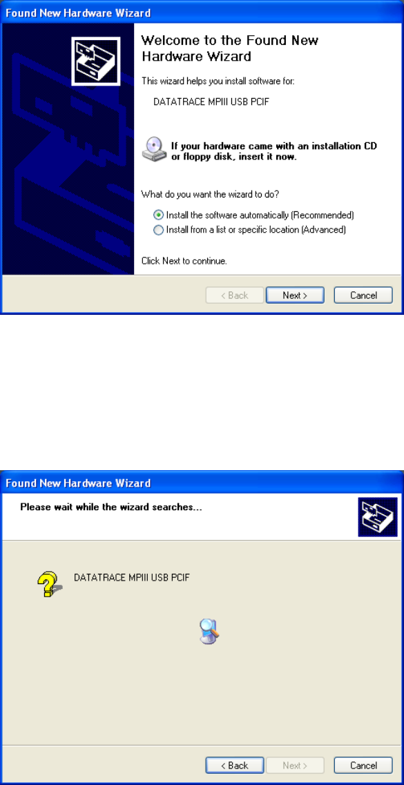
Connect the USB cable to the back of the PC Interface module, and then connect the other
end of the cable to an open USB port on your computer. Soon after this connection is made
a “balloon” will appear on the bottom right of your screen stating that “New Hardware
Found” and identifying it as “DATATRACE MPIII USB PCIF”.
8 of 27 pages
The following “Found New Hardware Wizard” screen will appear within a few moments:
• Verify that the CD with the USB Drivers is in the CD drive on your computer.
• Under the “What do you want the wizard to do?” select “Install the software
automatically (Recommended)”
• Click “Next”.
The next screen will appear as the appropriate files are retrieved and installed from the CD.
9 of 27 pages
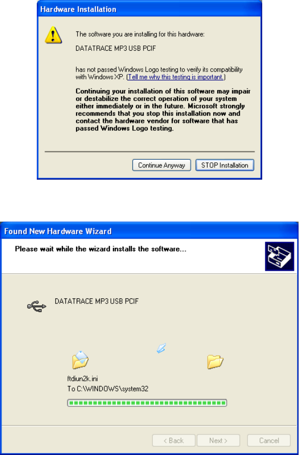
The following message will appear during the installation process. Ignore it by pressing
“Continue Anyway” button.
The installation process will continue.
10 of 27 pages
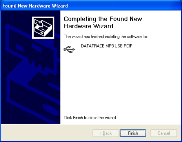
When the files are retrieved and installed, the Next button will become active. Click the
Next button and the following screen will appear indicating that the DataTrace MPIII USB
Interface installation is complete.
Click the Finish button.
The second installation program for the USB Serial Port will now start. Many similar
screens from the DataTrace USB PCIF installation will appear again, except they now
indicate the “USB Serial Port” is being installed.
As before a “balloon” will appear on the bottom right of your screen stating that “New
Hardware Found” and identified as “USB Serial Port”.
11 of 27 pages
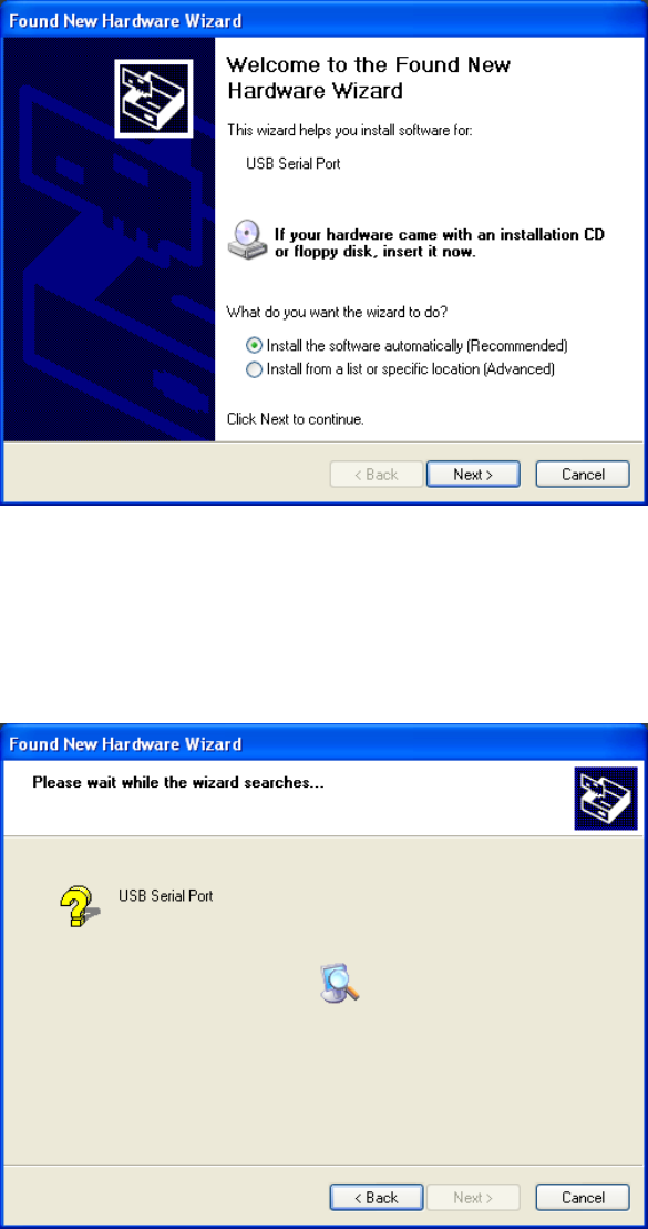
The following “Found New Hardware Wizard” screen will appear:
• Under the “What do you want the wizard to do?” select “Install the software
automatically (Recommended)”
• Click “Next”.
The next screen will appear as the appropriate files are retrieved and installed from the CD.

12 of 27 pages
The following message will appear again during the installation process. Ignore it by
pressing “Continue Anyway” button.
As before, the installation process will continue.
13 of 27 pages
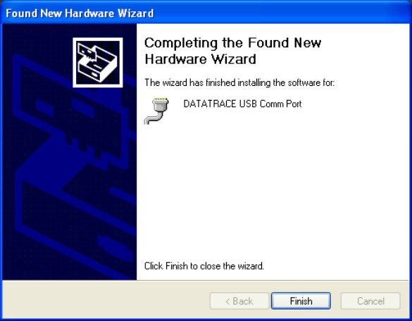
When the files are retrieved and installed, the Next button will become active. Click the
Next button and the following screen will appear indicating that the DataTrace USB Comm
Port installation is complete.
Click the Finish button to complete the installation program. You are now ready to use
your DataTrace RF system.
Congratulations. Now that your DataTrace® hardware is connected to your computer and you have
installed the DataTrace® RF program, you are ready to work with your system.
Create a short cut to the DTMPRF program on your desktop. Double click the DataTrace®
MPRF icon, which will start your DataTrace® RF program.
DataTrace RF Operational Instructions
DTENV will automatically search for connected interfaces. It is important to connect your
USB interface(s) to your computer’s USB ports prior to starting the application.
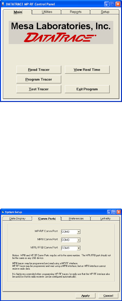
When DTENV is first accessed, the Main tab screen is displayed, which includes access to
screens for Programming (starting), Reading, Testing and Viewing the Real Time data of
MP-RF type Tracers and DTENV type devices.
14 of 27 pages
Setup
Before performing any of these functions, the Comm port setup must be defined in the
Setup tab. Once setup selections have been defined following initial installation, it is not
normally necessary to adjust them again; the application will retain its settings from session
to session.
Clicking the 'Setup' Tab will display the Setup screen, with the following options that can
be used to configure your DataTrace RF system: Data Display, Comm Ports, Preferences,
and Lethality.
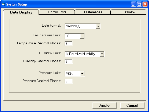
'Comm Ports' Settings
Note that the only setting that must be established initially is the Comm Ports. Other items
may be left at their factory default configurations or changed based on your needs.
15 of 27 pages
There are three types of DataTrace loggers, the SMT (also known as MPII or FRB
types, depending on model), the MPIII and the MP-RF. The SMT type uses an older
style PC Interface connected to a serial comm port (RS-232-C). MPIII and MP-RF
types have a newer Interface designs usually connected to a USB port. However, an
MPIII can be programmed and read with an MP-RF type and vice versa. Finally, to
receive MP-RF radio data, a MP-RF style interface (hereafter called the Host) with
radio antenna is required. Since the MP-RF receiver must be programmed to match the
Tracers, the MP-RF Tracers should be programmed on the MP-RF Host intended to
receive their data.
Set the comm port for each of the interface types you intend to use. The same Comm
port designation can be used for multiple Interfaces.
'Data Display' Parameters
Select the desired units of measure (e.g. for temperature °C or °F) and the number of
decimal places to be displayed for each parameter.
16 of 27 pages
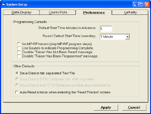
'Preferences' Settings
The preference settings affect how the software behaves when programming or reading
Tracers. Most options are self-explanatory.
The 'Default Start Time Minutes' option defines how far in the future data logging will
begin when first entering the Program Tracers screen, rounded upward as defined by
the 'Round Default Start Time boundary' setting. For example, for a boundary setting of
15 minutes, if hh represents the starting hour, the start time is forced to hh:00; or hh:15
or hh:30 or hh:45. While this boundary rounding is only specifically required for the
synchronization of MP-RF radio communications, it is applied to all Tracer types.
Data Saving Preferences: DTENV can save data to the standard DataTrace for
Windows database (Version 4.04 or greater) or it can save data in text files (located in
the subdirectory "Data" where DTENV is installed (usually C:\Program
Files\DTMPIV").
Options are provided to save collected data into DTENV's 21 CFR Part 11 compliant
database (allowing full use of all standard DTENV reports and data basing functions),
to the text files, or to both. DTENV will verify the presence of DTENV and an
appropriate version, and generate an error message if there is an incompatibility. The
text files are automatically named and are tab separated, allowing for easy importing
into a spreadsheet or other program.
17 of 27 pages
Programming Tracers
Clicking on the Program Tracer button from the Main tab will launch the Program Tracer
Wizard. This wizard consists of four screens which are accessed sequentially by the
conventional 'Next' or 'Back' buttons. The 'Next' button will not be enabled (will not
respond) until all required information on the current screen has been properly entered;
status messages will be displayed for missing or erroneous information.
Of the four screens in the wizard, two are applicable only to MP-RF Tracers. If you do not
use this type of Tracer, there is an option in the Setup\Preferences to skip the MP-RF
screens. Any attempt to program an MP-RF Tracer when these screens have been skipped
will result in an error and require proper completion of all screens.
While DTENV will allow programming of all types of Tracers, the user must select which
type is currently being programmed. Select the appropriate type of Tracer from the drop-
down list in the upper right corner of the screen. While the Tracer type can be changed at
any time during a programming session, we recommend grouping the Tracers by type and
program each type in its entirety before proceeding to the next group.(e.g., you may
program MP-RF's, then change to MPII and program them with the same parameters).
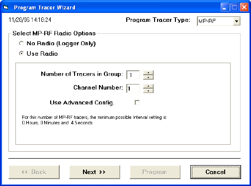
Program Wizard Screen # 1
Screen #1: "MP-RF Radio Options"
Select the MP-RF option to enable the Tracer's radio. Note: The radio function is a
significant draw on the battery; use the radio function only when it is needed.
Note: The radio is not to be used for data acquisition during the calibration procedure.
When the Radio function is enabled, the following Radio Configuration Parameters will be
shown:
18 of 27 pages
Number of Tracers in Group: Each MP-RF Tracer requires a specific time slot for
communications, consisting of a 1 second window some number of seconds after
the Tracer logs data. This time slot is called Member Number, and DTENV will
assign it automatically. The Member Number must be less than the sample interval
(in seconds), therefore the Number of Tracers in Group determines the minimum
allowable interval; this minimum interval is displayed. This information is
displayed on the second screen of the wizard.
Channel Number: This value determines the zigbee channel the radio will operate
on. Allowed values are 0 through 15. If there are other zigbee devices in use (which
will typically also have a configurable channel number), it would be preferable to
use a different channel.
If there are other MP-RF users, or it is desired to keep distinct groups of MP-RF
Tracers, each user or group should use a distinct channel. If Repeaters (a type of
MP-RF that rebroadcasts data) are to be used in this system configuration, a
separate channel should be assigned to it in order to allow longer range. More
details on repeaters are given at the "View Real Time" section, which contains
diagnostics for determining the presence of non-MP-RF communications.
Advanced Configuration (For advanced users only): When checked, allows the
user to access the advanced configuration utility. This utility allows the user to
bypass DTENV's automatic assignment of Member Number, Channel and some
other radio parameters, and configure the Tracers manually. Details are given in
Appendix TBD.
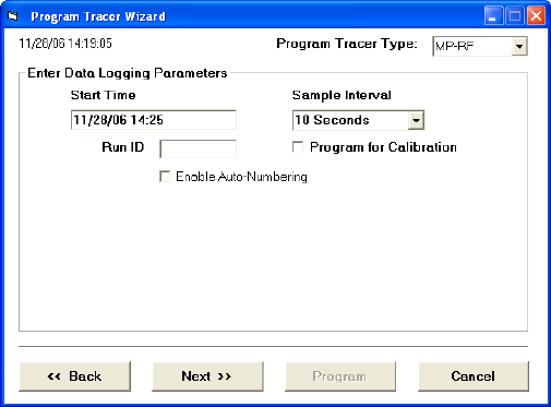
Program Wizard Screen # 2
Screen #2: "Data Logging Parameters"
19 of 27 pages
Start Time and Sample Interval: Enter the desired Start Time and Sample Interval.
Specifically, the date and time the Tracer(s) are to begin logging data and the interval
for data collection.
Run ID: IF desired, enter a Run Identification, up to 8 characters. It may be the same
for all Tracers, or different if desired. The Enable Auto-Numbering option allows
automatic assignment of a unique Run ID to each Tracer.
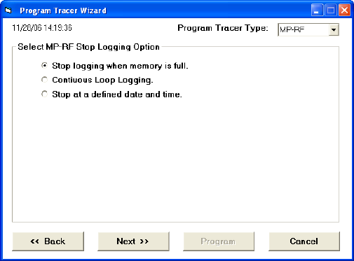
Program Wizard Screen # 3
Screen #3: "MP-RF Logging Parameters"
MP-RF Tracers will stop logging data based on the selected option. The MPII and MPIII
types do NOT support these options.
Stop Logging When Memory is Full: This option behaves the same as MPII or MPIII
types, and is dependant on the type and memory capacity of the Tracer (for MP-RF, 8000
points for a single channel temperature Tracer, 4000 for dual channel such as RH Tracers)
Continuous Loop Logging: The Tracer enters into a continuous loop and will never stop
logging or reporting measurements, where the oldest data is overwritten by newer data
when the memory is filled. Caution: When a Tracer is read, the reported Start Time will be
the time of the oldest available point. Note however, if Continuous Loop Logging is
enabled, the originally programmed Start Time may have been overwritten.
When a group of Tracers using this mode is read, it is possible the reported data will have
different starting times, which will cause difficulty when trying to generate complex reports
and graphs. This mode is recommended only for those applications where the intent is
simply to monitor real-time.
Stop at a Defined Date and Time: Self-explanatory.
20 of 27 pages
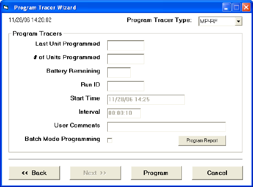
Program Wizard Screen # 4
Screen #4: "Program Tracers"
Review the Start Time and Interval settings. Modify the Run ID if desired. Within the
Program Tracers screen the Start Time and Sample Interval may not be changed. Use the
'Back' button to go back and edit these values if desired. Note: After the first Tracer has
been programmed, the 'Back' button will not be available, and the Start Time and Interval
are fixed for the current programming session.
Place a Tracer in the interface and verify the selected Tracer type (upper right corner)
matches. Click the Program button to apply the settings to the Tracer. Upon successful
completion "Last Unit Programmed" will show the serial number of the programmed
Tracer. A "Tracer Programmed" message will also be generated to indicate programming
success, unless this message was disabled in the system setup preferences. Remove the
Tracer from the interface and program the next one if desired, alternatively, the Tracer type
may be modified, and a different type programmed.
Batch Mode Programming: If this option is selected, a programming loop is initiated
when the Program button is clicked, and the Program button will change to "Stop". Upon
successful programming, "Waiting for Next Tracer" will be displayed; remove the Tracer
from the interface and put the next one in; programming will occur automatically. When all
Tracers of the selected Tracer type have been programmed, click "Stop".
If you wish to program more Tracers of a different type, select the type and batch mode can
be restarted. Tracer type may not be changed while batch mode programming is in
progress. Batch mode is also aborted automatically by any communications error; the
“Stop" button will change back to 'Program' and after noting the error and/or taking
corrective action, 'Program' must be clicked again to start the programming loop.
If during programming the current time surpasses the program Start Time, programming
will no longer be allowed. This condition will be indicated by the color of the Start Time
21 of 27 pages
changing to red. Should this occur, Start Time can be incremented in whole Sample
Intervals by use of the adjacent 'Increment' button (visible only when this condition exists).
If an attempt is made to program a Tracer which contains data which has not been read or
saved, a " Tracer has not been read" warning message will be displayed, unless this
message was disabled in the system setup preferences.
At any time the “Program Report” button can be clicked in order to see a listing of the
Tracers programmed during the current session.
When all Tracers have been programmed, click the 'Close' button to return to the Main
screen.
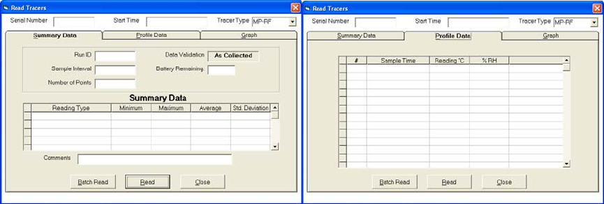
Reading Tracers
Click the Read Tracers button from the Main screen to access data retrieval functions.
To read a Tracer place it in the interface, verify the appropriate Tracer type is selected
(upper right corner) and click the 'Read' button. Note: When entering the Read Tracers
screen, a Tracer may be read automatically if the "Auto-Read on Entry" option was
selected is system setup preferences, the auto-read will be attempted using the Tracer type
last employed by the Read, Program or Test Tracer screens.
Three views (tabs) are provided; a Summary view, a Profile view consisting of the data and
time it was logged, and a Graph view. Tracers may be read regardless the selected view.
Summary View Profile View
22 of 27 pages
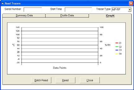
Graph View
The Y axis of the graph (and the second Y axis if the Tracer has two channels) can be
scaled by clicking on the axis; An inquiry will be generated for the desired lowest and
highest axis values. Adjusting the X axis range is not supported at this time.
Data is automatically saved immediately after the Read is complete. Data is saved in the
format(s) specified by the Save Data options in system setup preferences.
View Real Time Data
The View Real Time button accesses a screen which allows incoming MP-RF radio data to
be viewed and logged. This screen can only be accessed if there is a MP-RF interface
connected to the computer.
Data display will begin as soon as radio data is received. In general, this will happen once
the Tracers reach the programmed Start Time. Data can only be received for Tracers
transmitting on the Host receivers channel setting (displayed in the upper left corner).
At the top left of the screen are the menu items "File", "Edit" and "Utilities". The functions
provided by these menus are context sensitive, that is, their action depends on what is being
viewed. For example, Edit>Copy will copy data if the user is currently viewing real time
data, but would copy the Graph if that was being viewed. Similarly, the contents of the
Utilities Menu will change depending on which view is invoked.
There are five (5) views provided, accessed by the tabs.
Real Time
The Real Time screen supports the ability of MP-RF Tracers to transmit via radio the
measured data. The data is transmitted between data acquisitions (sample intervals). All
transmitted data is also logged within the Tracer and can be retrieved through the Read
Tracer process. The successful reception of radio data is contingent upon many factors
beyond the control of Mesa Laboratories, Inc and DTENV, including constraints such as
23 of 27 pages
distance, other interfering radio sources, proper system configuration, walls, floors, and
other obstacles, and perhaps most importantly, Faraday's law, which states that radio
signals will not travel through conductive materials (e.g. metals).
If an MP-RF Tracer is placed in a sealed metal container, there can be very little
expectation of successful radio transmission. However, for ovens, autoclaves, metallic
freezers or sterilization chambers there is a good probability of radio communication if
there is a non-conductive gasket employed on the door seal, or some non-conductive
portion of the enclosure which has at least one dimension longer that 6" (the wavelength of
the radio signal). Conditions such as these may limit the distance of transmission, requiring
the Host to be placed relatively close to the Tracers, or using a repeater. In general, prior to
actual use, it is advisable to perform some preliminary testing to verify radio
communications feasibility and performance.
While it is common that some radio data will not be received (90 % reception is a stated
industry standard), DTENV and the MP-RF Tracers have unique features for retrieving
missed data. This process occurs automatically, but only when communications are good;
getting all data via radio may require the user to place the Tracers near the Host (good
communications) to retrieve any missing data points after process completion.
The Real Time view displays incoming radio data from MP-RF Tracers in a columnar
format. The display will include the Tracer's Serial Number, Run ID, and the measured
value(s) with units of measure. Other information can also be displayed, customizable by
clicking the Display Options button and selecting the desired options, which include:
Alarms: When enabled, the measured value is evaluated per the adjacent alarm
settings. The value is displayed in black when normal, red if the High Limit is
exceeded, or blue if lower than the Low Limit.
Time Stamp: The date and time the data was measured.
Tracer Start Time and / or Interval: The current settings of the Tracer
Tracer Reading Number: Self-explanatory, it may be used to determine
how soon the Tracer's memory will be full or how much data there is to
read.
Four diagnostics are provided:
Group ID and Member Num.: The group ID is normally the numeric portion of
the serial number of the Host receiver. The Host will receive data from any Tracer,
but will only acknowledge and transmit instructions to those within its own group.
Only data from the Host's own group can be logged, saved or graphed. The Member
Number (discussed at Program Tracers) should be unique for each Tracer. If two
Tracers have the same Member Number, their communications efficiency will be
greatly diminished. Problems with Group ID or Member Number are usually caused
by different groups of Tracers being programmed for the same channel or being
programmed on one interface and being received with a different Host (to do this
requires using the Advanced Configuration option when programming).
24 of 27 pages
Elapsed Seconds since Last Data Reception: should not be greater than the
Sample Interval.
Signal Diagnostics: Causes the display of three signal parameters:
1. dB is the radio signal strength of the signals received by the Tracer,
2. Host dB is the signal strength of signals received by the Host. Signal
strength in the range of -20 db to -60 db are considered excellent, while a
-98 db is a very weak signal.
3. Communications Mode is also displayed and has two states:
• OK for normal radio communications, and
• NB when the communications are not bi-directional. "NB" means
that even though data is being received, the Tracer cannot receive
any instructions, and some features (e.g. programming via radio) will
not be allowed.
Battery % Remaining: Self explanatory.
Comm Fail Warnings Settings: Should communications fail, the displayed
measured value will eventually be erased after the "Clear Data Display" number of
sample intervals without communication has elapsed. The entire display row will be
removed once the "Remove Display Row" number of intervals has passed.
Show Summary: When set, a summary of the incoming data will be displayed,
which includes the number of Tracers of each type and the minimum, maximum,
average, spread and standard deviation of the current readings?
Note on timing or availability of the displayed information: Each MP-RF
transmission contains standard information which includes its serial number, data
time stamp, the data and miscellaneous parameters. More detailed information such
Tracer Start Time or Run ID is transmitted only when requested. When first
viewing the display, the more detailed information may not be immediately
available.
Logging
Warning: Radio data is not automatically logged or saved.
To log the data, click the 'Start' button. The button will change to 'Stop', which will
stop logging when clicked.
Once a minimum of 3 rows of data have been logged, the graph will be available.
The graph only displays logged data.
Recovering Previous Data: If a logging session is started after the Tracers have
already logged data, the pre-existing data can be retrieved. From the Utilities menu,
25 of 27 pages
select "Recovery Previous Data", and enter the date and time of the first point to be
recovered. The date and time must not be earlier than the start time of the Tracers
(DTENV will verify). Upon entry of a valid date, the log will be populated with
new rows and the data recovery process will begin automatically.
Data recovery requires precise knowledge of the Tracer's Start Time and Sample
Interval. Data recovery will not commence for a Tracer until such time as
communications quality has been sufficient to retrieve this information. The speed
of data recovery is also highly dependant on communications quality. At its best,
the data recovery routine acquires 16 sequential readings per interval (for a dual
channel Tracer this might be 8 temperature and 8 RH readings, or 8 intervals worth
of data). While the designed functionality is intended to retrieve small amounts of
missed data, this feature may be used like a Read Tracer via radio function;
however, this may require a significant amount of time. It is left to the user to
decide if reading the Tracer in the PC interface is more efficient.
Data may be saved by clicking the 'Save' button; it will be saved in the format
specified by system setup preferences.
Warning: When saving data to the DTW database, 21 CFR Part 11 compliance and
security issues will not allow any further modifications to the data file, which
disallows the addition of new data. Subsequent radio data can therefore no longer
be saved to this profile record. When using the DTW database, it is preferable to
acquire all the data desired, then Stop the logging process and save the data. Should
it be absolutely necessary to save new data to DTW, the existing data must be
removed using the Delete option in DTW's Archive Profile function, an action
which may also require security clearances (refer to the DTW manual for details).
The 'Clear' button can be used to clear the existing data in preparation for a new
logging session. If the data has not been saved a message will be displayed and the
user is given the opportunity to abort and save the data.
Warning: Pressing 'Start' will erase any existing data. If the data has not been saved
a message will be displayed with the opportunity to save the data.
26 of 27 pages
Network
The network screen provides methods to control the Tracers via the radio. On the left-side
of the screen is displayed the current Tracer network configuration, showing the Host, the
Tracers, and any repeaters which may be in use.
Program via Radio: MP-RF Tracers may be reprogrammed via the radio. Programming
via radio does require that communications be bi-directional for all Tracers (DTENV will
advise if this condition is not met). Programming is not allowed while data logging is
enabled.
To reprogram the Tracers, enter the new Start Time and Sample Interval, and click
program. DTENV will transmit the new parameters to the Tracers and verify the reception
of the command. Programming status will be shown in the network configuration diagram.
After all Tracers have been re-programmed, DTENV will reprogram any repeaters and the
Host automatically. The entire process will normally require 2 to 3 sample interval periods.
Upon completion, a message indicating reprogramming is completed will be displayed. It is
normal for communications to be interrupted for a few intervals or until the new start time
arrives.
Add a Tracer: This button adds a Tracer to the current group. In order to add a Tracer, a
member number must be assigned to it (see Program Tracer for Member Number details).
The new member number may not exceed the interval limit. Member number can be
viewed in the real time display by selecting that option.
If the Tracer to be added is replacing a malfunctioning one, it is preferable to use the
malfunctioning Tracer’s member number. Place the Tracer to be added in the Host
interface and click the button. Enter the channel (default to the host channel) and member
number (defaults to the next available one). The Tracer will be programmed to start
immediately at an interval which matches the group and logging data at the same time as
the group. Upon completion, a message is displayed and the option to add another Tracer is
given. Note that added Tracers will have different start times that the original group.
Add a Repeater: This button adds a repeater to the current group. DTENV will ask for a
member number (same as adding a Tracer), and the repeater's re-transmission channel. By
default, the repeater will be configured to receive data on the channel currently assigned to
the host. The host will be automatically re-configured to receive data from the repeater.
Remove a Repeater: This button performs the inverse of Adding a Repeater. The repeater
will be stopped, and the host will be reconfigured to receive data from the channel the
repeater was receiving data on.
Configure Host: A utility which allows manually setting the Host's channel and Group ID.
Intended for advance network control and not normally used.
27 of 27 pages
Spatial Map
The Spatial Map provides a method of viewing incoming data against a backdrop
consisting of a user defined picture, map, or graphical process representation, with the
ability to position each Tracer's data relative to this image.
For each transmitting Tracer, a box is available which displays the Tracer's data, Serial
Number or Run ID identification. This box can be moved anywhere within the picture by
dragging the box (while holding down the left mouse button).
Setup options for the Spatial Map are accessed from the Utilities menu, "View Spatial
Display Options", which includes a button to import a picture. The picture may be any
standard windows picture file (e.g. bitmap or jpeg). A sample file named "3 shelves.bmp"
is provided, which can be easily edited using any bitmap editor (e.g. Paintbrush.exe) to
create a desired backdrop.
Using the options, choose what information to display, and whether to apply alarms, which
cause the backdrop of the data to change colors depending on the setting for the alarm
values. The colors chosen for the alarms can be changed by double clicking the color box.
Graph
The graph is available only for logged data (see "Logging" section).
The "View Options" button accesses the graph configuration options. These include
choices for what to plot (Temperature, RH or both) and on which axis to plot (left axis
standard, 2nd Y is the right axis). Options are also available to hide the legend, plot in black
and white, and Auto-refresh the graph on reception of new data (if not selected, the graph is
only refreshed once when entering the graph screen. Note: If a large number of Tracers or
data is being plotted, and this action interferes (takes longer then the time between
transmissions) with the reception of radio data, DTENV will disable the auto refresh
option.