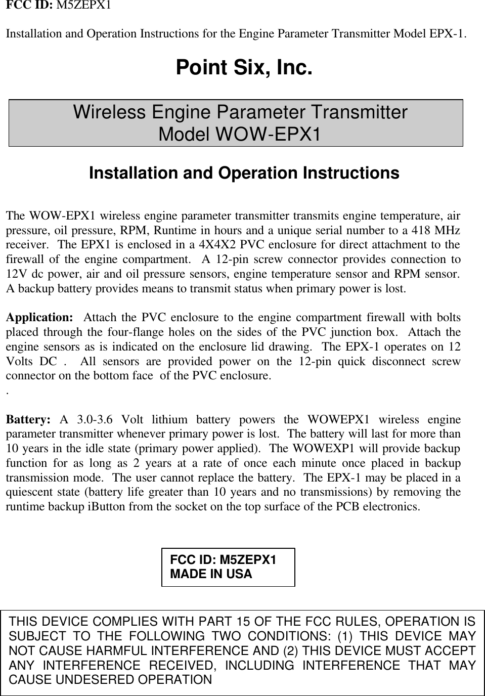
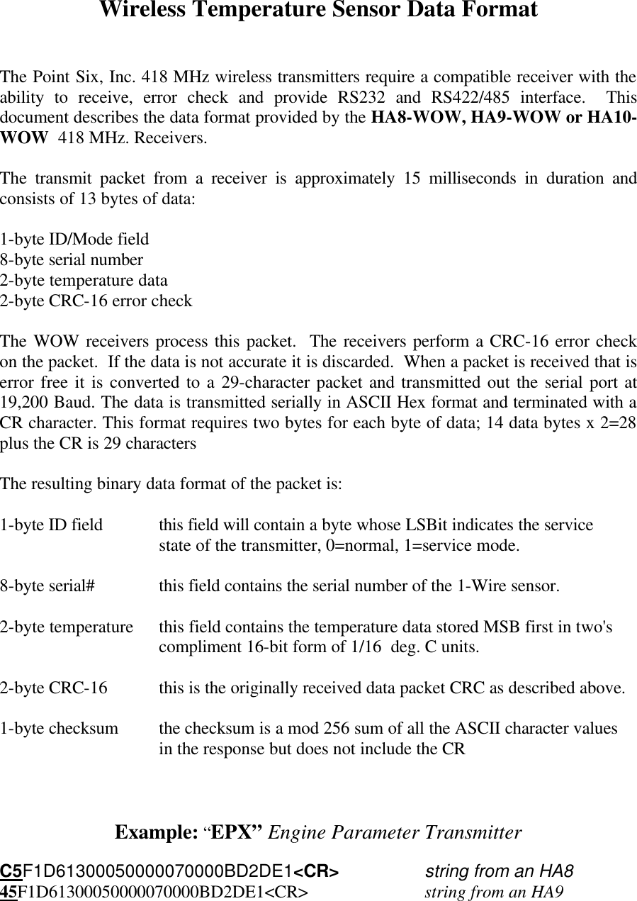
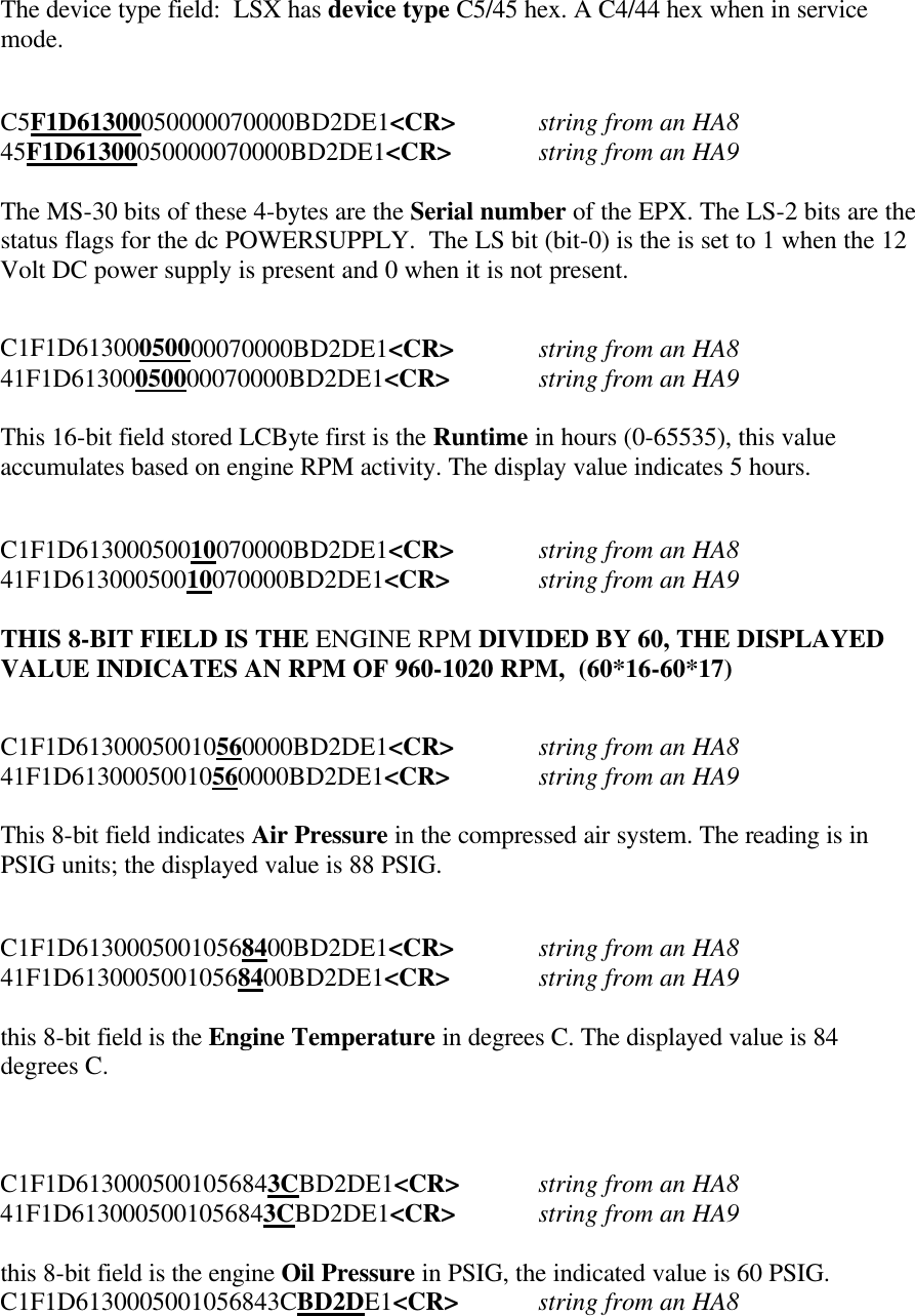
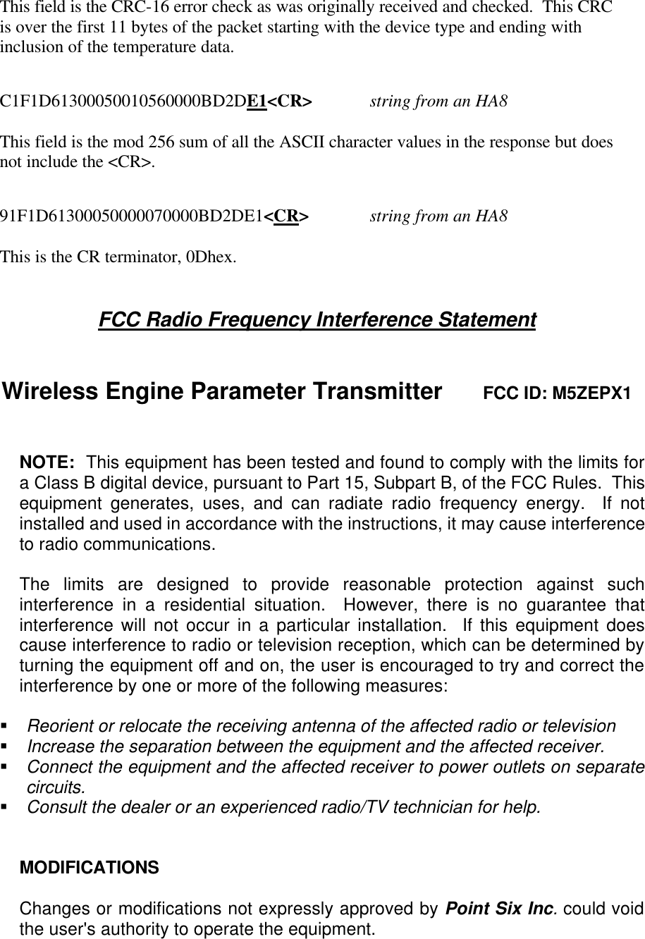
Mesa Laboratories EPX1 Engine Parameter Transmitter User Manual 01dBi019 User s Man

Point Six Inc Engine Parameter Transmitter 01dBi019 User s Man

users manual

FCC ID: M5ZEPX1  Installation and Operation Instructions for the Engine Parameter Transmitter Model EPX-1.  Point Six, Inc.  Wireless Engine Parameter Transmitter  Model WOW-EPX1  Installation and Operation Instructions   The WOW-EPX1 wireless engine parameter transmitter transmits engine temperature, air pressure, oil pressure, RPM, Runtime in hours and a unique serial number to a 418 MHz receiver.  The EPX1 is enclosed in a 4X4X2 PVC enclosure for direct attachment to the firewall of the engine compartment.  A 12-pin screw connector provides connection to 12V dc power, air and oil pressure sensors, engine temperature sensor and RPM sensor. A backup battery provides means to transmit status when primary power is lost.  Application:  Attach the PVC enclosure to the engine compartment firewall with bolts placed through the four-flange holes on the sides of the PVC junction box.  Attach the engine sensors as is indicated on the enclosure lid drawing.  The EPX-1 operates on 12 Volts DC .  All sensors are provided power on the 12-pin quick disconnect screw connector on the bottom face  of the PVC enclosure. .   Battery: A 3.0-3.6 Volt lithium battery powers the WOWEPX1 wireless engine parameter transmitter whenever primary power is lost.  The battery will last for more than 10 years in the idle state (primary power applied).  The WOWEXP1 will provide backup function for as long as 2 years at a rate of once each minute once placed in backup transmission mode.  The user cannot replace the battery.  The EPX-1 may be placed in a quiescent state (battery life greater than 10 years and no transmissions) by removing the runtime backup iButton from the socket on the top surface of the PCB electronics.           THIS DEVICE COMPLIES WITH PART 15 OF THE FCC RULES, OPERATION IS SUBJECT TO THE FOLLOWING TWO CONDITIONS: (1) THIS DEVICE MAY NOT CAUSE HARMFUL INTERFERENCE AND (2) THIS DEVICE MUST ACCEPT ANY INTERFERENCE RECEIVED, INCLUDING INTERFERENCE THAT MAY CAUSE UNDESERED OPERATION  FCC ID: M5ZEPX1 MADE IN USA
Wireless Temperature Sensor Data Format   The Point Six, Inc. 418 MHz wireless transmitters require a compatible receiver with the ability to receive, error check and provide RS232 and RS422/485 interface.  This document describes the data format provided by the HA8-WOW, HA9-WOW or HA10-WOW  418 MHz. Receivers.  The transmit packet from a receiver is approximately 15 milliseconds in duration and consists of 13 bytes of data:  1-byte ID/Mode field 8-byte serial number 2-byte temperature data 2-byte CRC-16 error check  The WOW receivers process this packet.  The receivers perform a CRC-16 error check on the packet.  If the data is not accurate it is discarded.  When a packet is received that is error free it is converted to a 29-character packet and transmitted out the serial port at 19,200 Baud. The data is transmitted serially in ASCII Hex format and terminated with a CR character. This format requires two bytes for each byte of data; 14 data bytes x 2=28 plus the CR is 29 characters  The resulting binary data format of the packet is:  1-byte ID field this field will contain a byte whose LSBit indicates the service state of the transmitter, 0=normal, 1=service mode.  8-byte serial# this field contains the serial number of the 1-Wire sensor.  2-byte temperature this field contains the temperature data stored MSB first in two's compliment 16-bit form of 1/16  deg. C units.   2-byte CRC-16 this is the originally received data packet CRC as described above.  1-byte checksum the checksum is a mod 256 sum of all the ASCII character values in the response but does not include the CR    Example: “EPX” Engine Parameter Transmitter  C5F1D61300050000070000BD2DE1<CR>  string from an HA8 45F1D61300050000070000BD2DE1<CR>   string from an HA9
The device type field:  LSX has device type C5/45 hex. A C4/44 hex when in service mode.   C5F1D61300050000070000BD2DE1<CR>  string from an HA8 45F1D61300050000070000BD2DE1<CR>  string from an HA9  The MS-30 bits of these 4-bytes are the Serial number of the EPX. The LS-2 bits are the status flags for the dc POWERSUPPLY.  The LS bit (bit-0) is the is set to 1 when the 12 Volt DC power supply is present and 0 when it is not present.    C1F1D61300050000070000BD2DE1<CR>  string from an HA8 41F1D61300050000070000BD2DE1<CR>  string from an HA9  This 16-bit field stored LCByte first is the Runtime in hours (0-65535), this value accumulates based on engine RPM activity. The display value indicates 5 hours.   C1F1D61300050010070000BD2DE1<CR>  string from an HA8 41F1D61300050010070000BD2DE1<CR>  string from an HA9  THIS 8-BIT FIELD IS THE ENGINE RPM DIVIDED BY 60, THE DISPLAYED VALUE INDICATES AN RPM OF 960-1020 RPM,  (60*16-60*17)   C1F1D61300050010560000BD2DE1<CR>  string from an HA8 41F1D61300050010560000BD2DE1<CR>  string from an HA9  This 8-bit field indicates Air Pressure in the compressed air system. The reading is in PSIG units; the displayed value is 88 PSIG.   C1F1D61300050010568400BD2DE1<CR>  string from an HA8 41F1D61300050010568400BD2DE1<CR>  string from an HA9  this 8-bit field is the Engine Temperature in degrees C. The displayed value is 84 degrees C.    C1F1D6130005001056843CBD2DE1<CR>  string from an HA8 41F1D6130005001056843CBD2DE1<CR>  string from an HA9  this 8-bit field is the engine Oil Pressure in PSIG, the indicated value is 60 PSIG. C1F1D6130005001056843CBD2DE1<CR>  string from an HA8
This field is the CRC-16 error check as was originally received and checked.  This CRC is over the first 11 bytes of the packet starting with the device type and ending with inclusion of the temperature data.   C1F1D61300050010560000BD2DE1<CR>  string from an HA8  This field is the mod 256 sum of all the ASCII character values in the response but does not include the <CR>.   91F1D61300050000070000BD2DE1<CR>  string from an HA8  This is the CR terminator, 0Dhex.   FCC Radio Frequency Interference Statement    Wireless Engine Parameter Transmitter      FCC ID: M5ZEPX1   NOTE:  This equipment has been tested and found to comply with the limits for a Class B digital device, pursuant to Part 15, Subpart B, of the FCC Rules.  This equipment generates, uses, and can radiate radio frequency energy.  If not installed and used in accordance with the instructions, it may cause interference to radio communications.  The limits are designed to provide reasonable protection against such interference in a residential situation.  However, there is no guarantee that interference will not occur in a particular installation.  If this equipment does cause interference to radio or television reception, which can be determined by turning the equipment off and on, the user is encouraged to try and correct the interference by one or more of the following measures:  § Reorient or relocate the receiving antenna of the affected radio or television § Increase the separation between the equipment and the affected receiver. § Connect the equipment and the affected receiver to power outlets on separate circuits. § Consult the dealer or an experienced radio/TV technician for help.   MODIFICATIONS  Changes or modifications not expressly approved by Point Six Inc. could void the user's authority to operate the equipment.

Navigation menu