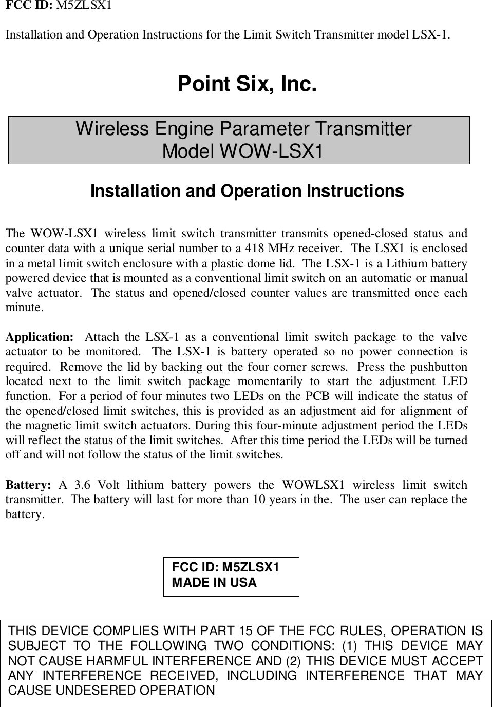
Mesa Laboratories LSX1 Wireless limit switch User Manual

Point Six Inc Wireless limit switch

user manual

FCC ID: M5ZLSX1Installation and Operation Instructions for the Limit Switch Transmitter model LSX-1.Point Six, Inc.Wireless Engine Parameter TransmitterModel WOW-LSX1Installation and Operation InstructionsThe WOW-LSX1 wireless limit switch transmitter transmits opened-closed status andcounter data with a unique serial number to a 418 MHz receiver.  The LSX1 is enclosedin a metal limit switch enclosure with a plastic dome lid.  The LSX-1 is a Lithium batterypowered device that is mounted as a conventional limit switch on an automatic or manualvalve actuator.  The status and opened/closed counter values are transmitted once eachminute.Application:  Attach the LSX-1 as a conventional limit switch package to the valveactuator to be monitored.  The LSX-1 is battery operated so no power connection isrequired.  Remove the lid by backing out the four corner screws.  Press the pushbuttonlocated next to the limit switch package momentarily to start the adjustment LEDfunction.  For a period of four minutes two LEDs on the PCB will indicate the status ofthe opened/closed limit switches, this is provided as an adjustment aid for alignment ofthe magnetic limit switch actuators. During this four-minute adjustment period the LEDswill reflect the status of the limit switches.  After this time period the LEDs will be turnedoff and will not follow the status of the limit switches.Battery:  A 3.6 Volt lithium battery powers the WOWLSX1 wireless limit switchtransmitter.  The battery will last for more than 10 years in the.  The user can replace thebattery.THIS DEVICE COMPLIES WITH PART 15 OF THE FCC RULES, OPERATION ISSUBJECT TO THE FOLLOWING TWO CONDITIONS: (1) THIS DEVICE MAYNOT CAUSE HARMFUL INTERFERENCE AND (2) THIS DEVICE MUST ACCEPTANY INTERFERENCE RECEIVED, INCLUDING INTERFERENCE THAT MAYCAUSE UNDESERED OPERATIONFCC ID: M5ZLSX1MADE IN USA
Wireless Temperature Sensor Data FormatThe Point Six, Inc. 418 MHz wireless transmitters require a compatible receiver with theability to receive, error check and provide RS232 and RS422/485 interface.  Thisdocument describes the data format provided by the HA8-WOW, HA9-WOW or HA10-WOW  418 MHz. Receivers.The transmit packet from a receiver is approximately 15 milliseconds in duration andconsists of 13 bytes of data:1-byte ID/Mode field8-byte serial number2-byte temperature data2-byte CRC-16 error checkThe WOW receivers processe this packet.  The receivers perform a CRC-16 error checkon the packet.  If the data is not accurate it is discarded.  When a packet is received that iserror free it is converted to a 29-character packet and transmitted out the serial port at19,200 Baud. The data is transmitted serially in ASCII Hex format and terminated with aCR character. This format requires two bytes for each byte of data; 14 data bytes x 2=28plus the CR is 29 charactersThe resulting binary data format of the packet is:1-byte ID field this field will contain a byte whose LSBit indicates the servicestate of the transmitter, 0=normal, 1=service mode.8-byte serial# this field contains the serial number of the 1-Wire sensor.2-byte temperature this field contains the temperature data stored MSB first in two'scompliment 16-bit form of 1/16  deg. C units.2-byte CRC-16 this is the originally received data packet CRC as described above.1-byte checksum the checksum is a mod 256 sum of all the ASCII character valuesin the response but does not include the CR
Example: “LSX”  Wireless Limit Switch Transmitter91F1D61300050000070000BD2DE1<CR> string from an HA811F1D61300050000070000BD2DE1<CR> string from an HA9The device type field:  LSX has device type 91/11 hex. A 90/10 hex when in servicemode.91F1D61300050000070000BD2DE1<CR> string from an HA811F1D61300050000070000BD2DE1<CR> string from an HA9The MS-30 bits of these 4-bytes are the serial number of the LSX. The LS-2 bits are thestatus flags for the open and closed limit switches.  The LS bit (bit-0) is the Open switchflag and the next most significant bit (bit-1) is the Closed switch flag.91F1D61300050000070000BD2DE1<CR> string from an HA811F1D61300050000070000BD2DE1<CR> string from an HA9This 24-bit field is the Open counter stored LS-byte first the value shown is a count of 5open cycles.11F1D61300050000070000BD2DE1<CR> string from an HA811F1D61300050000070000BD2DE1<CR> string from an HA9THIS 24-BIT FIELD IS THE CLOSED COUNTER STORED LS-BYTE FIRST,THE VALUE SHOWN IS A ACCOUNT OF 7 CLOSED CYCLES.91F1D61300050000070000BD2DE1<CR> string from an HA811F1D61300050000070000BD2DE1<CR> string from an HA9This field is the CRC-16 error check as was originally received and checked.  This CRCis over the first 11 bytes of the packet starting with the device type and ending withinclusion of the temperature data.
91F1D61300050000070000BD2DE1<CR> string from an HA811F1D61300050000070000BD2DE1<CR> string from an HA9This field is the mod 256 sum of all the ASCII character values in the response but doesnot include the <CR>.91F1D61300050000070000BD2DE1<CR> string from an HA811F1D61300050000070000BD2DE1<CR> string from an HA9This is the CR terminator, 0Dhex.FCC Radio Frequency Interference StatementWireless Limit Switch Transmitter       FCC ID: M5ZLSX1NOTE:  This equipment has been tested and found to comply with the limits fora Class B digital device, pursuant to Part 15, Subpart B, of the FCC Rules.  Thisequipment generates, uses, and can radiate radio frequency energy.  If notinstalled and used in accordance with the instructions, it may cause interferenceto radio communications.The limits are designed to provide reasonable protection against suchinterference in a residential situation.  However, there is no guarantee thatinterference will not occur in a particular installation.  If this equipment doescause interference to radio or television reception, which can be determined byturning the equipment off and on, the user is encouraged to try and correct theinterference by one or more of the following measures:! Reorient or relocate the receiving antenna of the affected radio or television! Increase the separation between the equipment and the affected receiver.! Connect the equipment and the affected receiver to power outlets on separatecircuits.! Consult the dealer or an experienced radio/TV technician for help.MODIFICATIONSChanges or modifications not expressly approved by Point Six Inc. could voidthe user's authority to operate the equipment.

Navigation menu