Meteorcomm 54506001-01 Meteor Burst Packet Data Radio For Fixed and Mobil User Manual Instruction User and Operations Manual Exhibit 8
Meteorcomm LLC Meteor Burst Packet Data Radio For Fixed and Mobil Instruction User and Operations Manual Exhibit 8
Instruction User and Operations Manual Exhibit 8


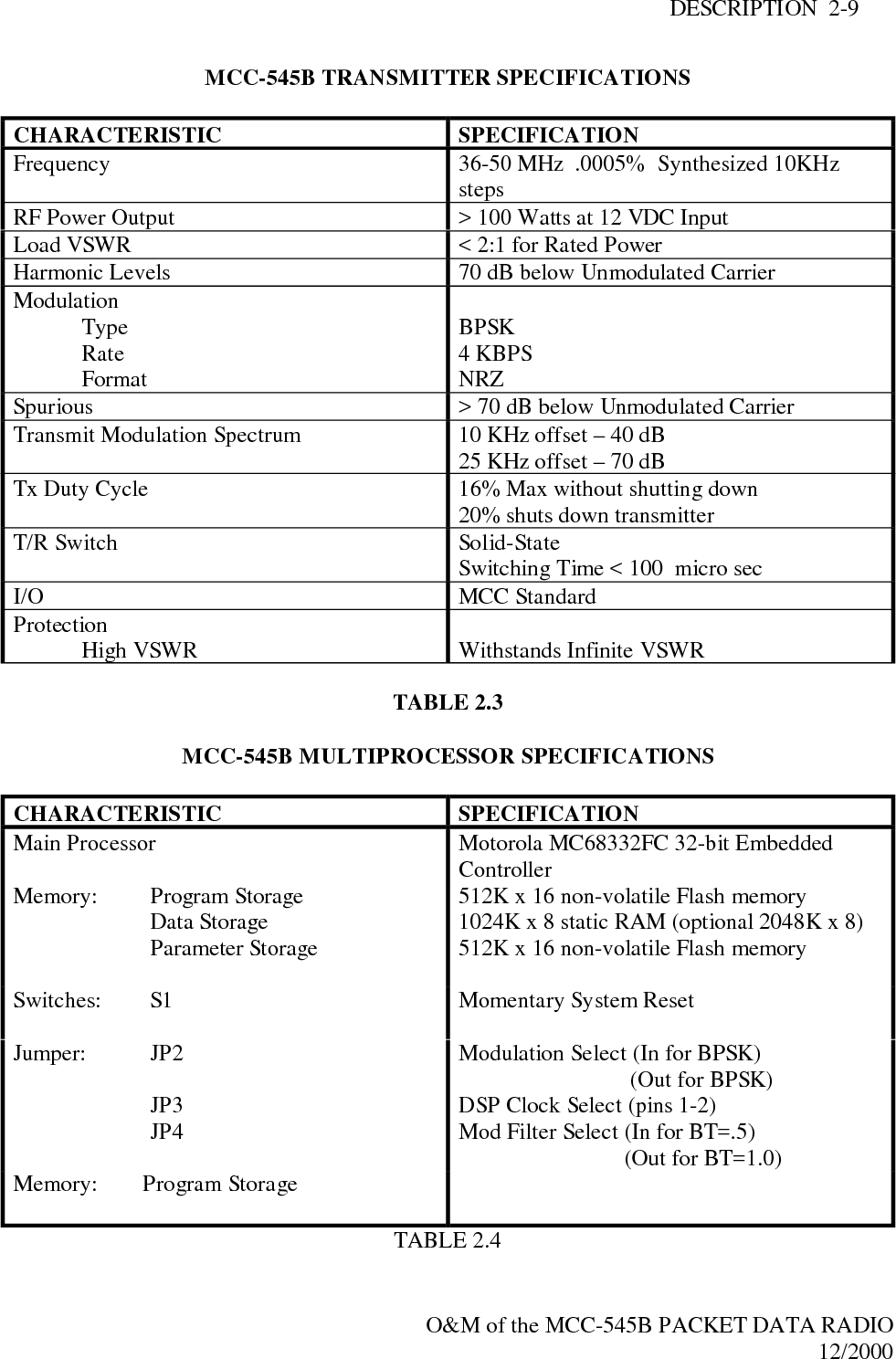
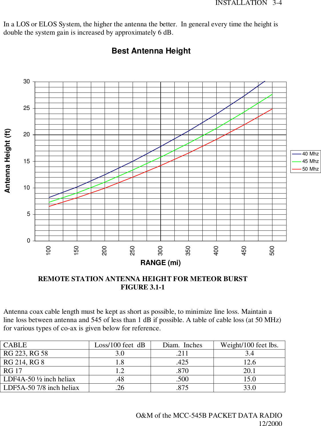
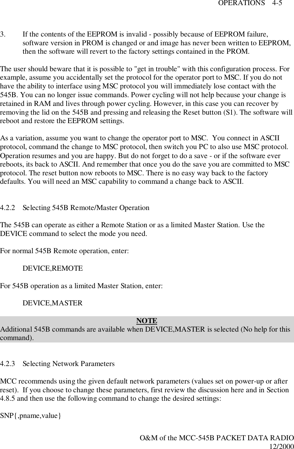
![INTRODUCTION 1-2O&M of the MCC-545B PACKET DATA RADIO12/20001.2 Support DocumentsCustomer Specific System ManualMCC-520B/MCC-520C Operations Manual1.3 ConventionsThe following conventions are used in this manual:Any system-dependent options are indicated with an "*".When presented in the text, user commands and computer printout are boldfaced; e.g., EnterDELETE. Command parameters are presented in lower case; e.g., DEFINE,id. Optionalparameters are enclosed in brackets; e.g., TIME{,hh:mm:ss}Names of terminal keys are capitalized and enclosed in square brackets when mentioned in thetext; e.g., Press [ESC].Names of hardware switches, meters, etc. are capitalized; e.g., PWR ON switch.NOTEUsed for special emphasis of materialIMPORTANTUsed for added emphasis of material.CAUTIONSignals the operator to proceed carefully.WARNING! WARNING! WARNING!Used in cases where failure to heed the message may result in personal injury or equipmentdamage.](https://usermanual.wiki/Meteorcomm/54506001-01/User-Guide-134278-Page-11.png)
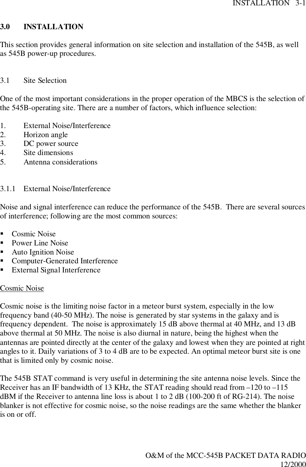
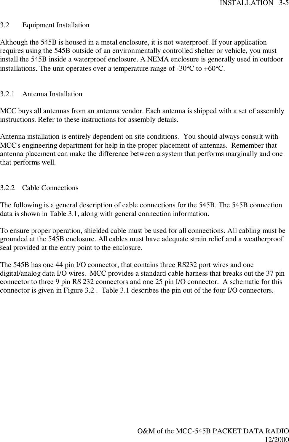
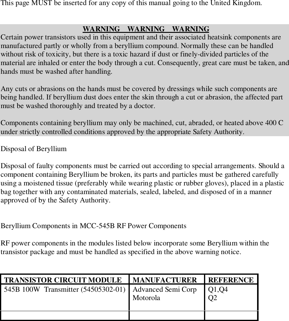
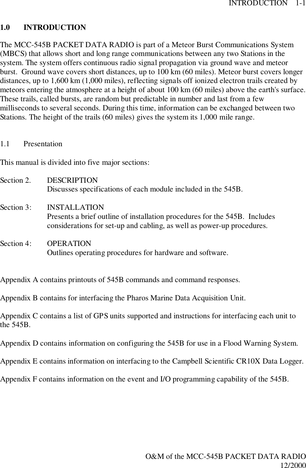
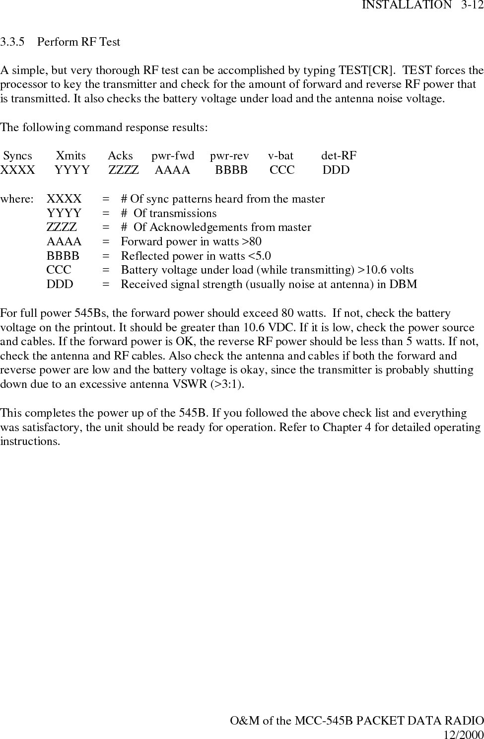
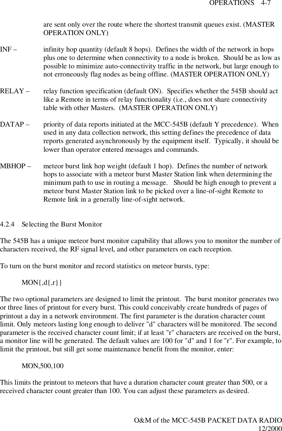
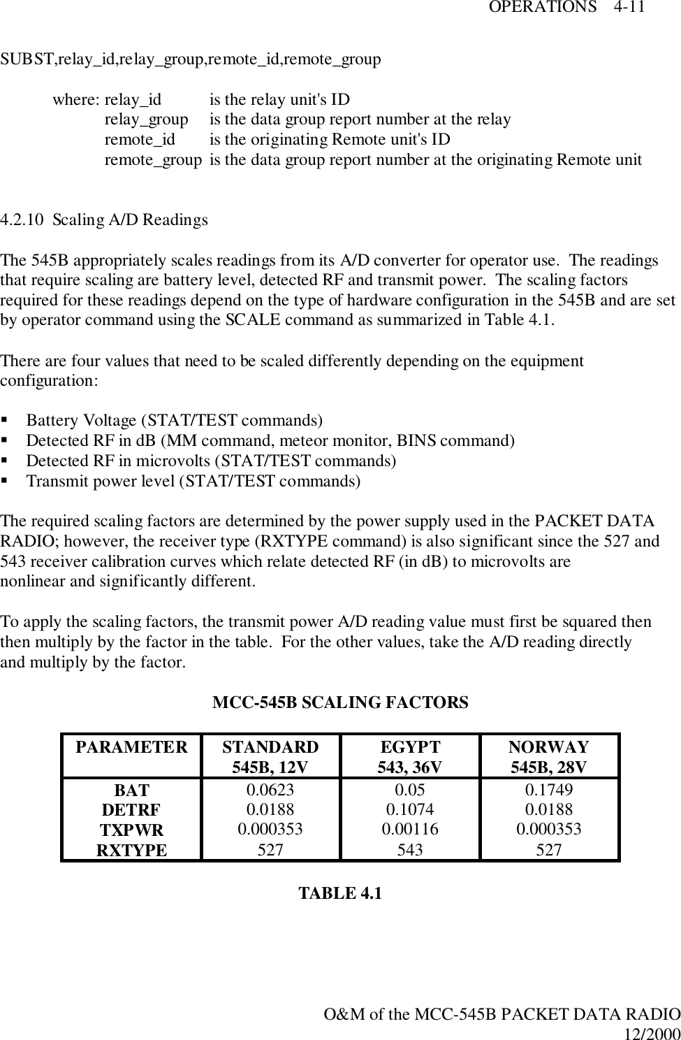
![INSTALLATION 3-12O&M of the MCC-545B PACKET DATA RADIO12/20003.3.5 Perform RF TestA simple, but very thorough RF test can be accomplished by typing TEST[CR]. TEST forces theprocessor to key the transmitter and check for the amount of forward and reverse RF power thatis transmitted. It also checks the battery voltage under load and the antenna noise voltage.The following command response results: Syncs Xmits Acks pwr-fwd pwr-rev v-bat det-RFXXXX YYYY ZZZZ AAAA BBBB CCC DDDwhere: XXXX = # Of sync patterns heard from the masterYYYY = # Of transmissionsZZZZ = # Of Acknowledgements from masterAAAA = Forward power in watts >80BBBB = Reflected power in watts <5.0CCC = Battery voltage under load (while transmitting) >10.6 voltsDDD = Received signal strength (usually noise at antenna) in DBMFor full power 545Bs, the forward power should exceed 80 watts. If not, check the batteryvoltage on the printout. It should be greater than 10.6 VDC. If it is low, check the power sourceand cables. If the forward power is OK, the reverse RF power should be less than 5 watts. If not,check the antenna and RF cables. Also check the antenna and cables if both the forward andreverse power are low and the battery voltage is okay, since the transmitter is probably shuttingdown due to an excessive antenna VSWR (>3:1).This completes the power up of the 545B. If you followed the above check list and everythingwas satisfactory, the unit should be ready for operation. Refer to Chapter 4 for detailed operatinginstructions.](https://usermanual.wiki/Meteorcomm/54506001-01/User-Guide-134278-Page-35.png)
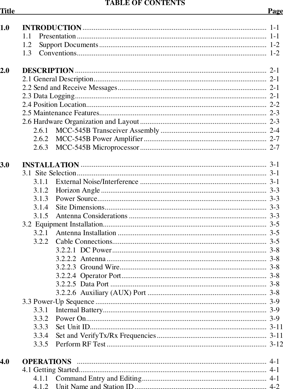
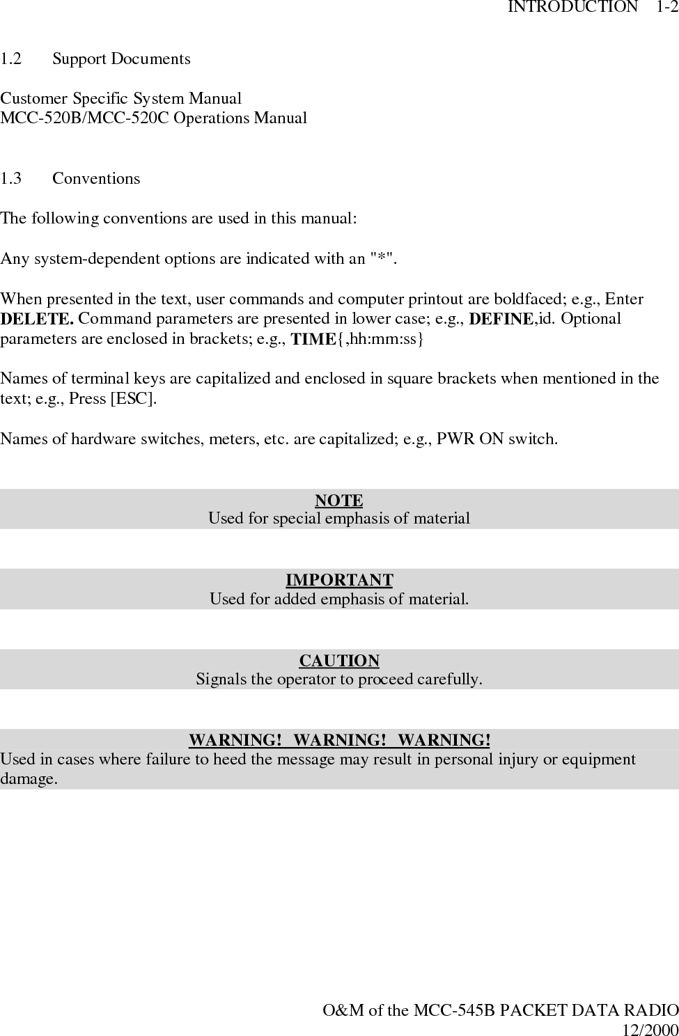
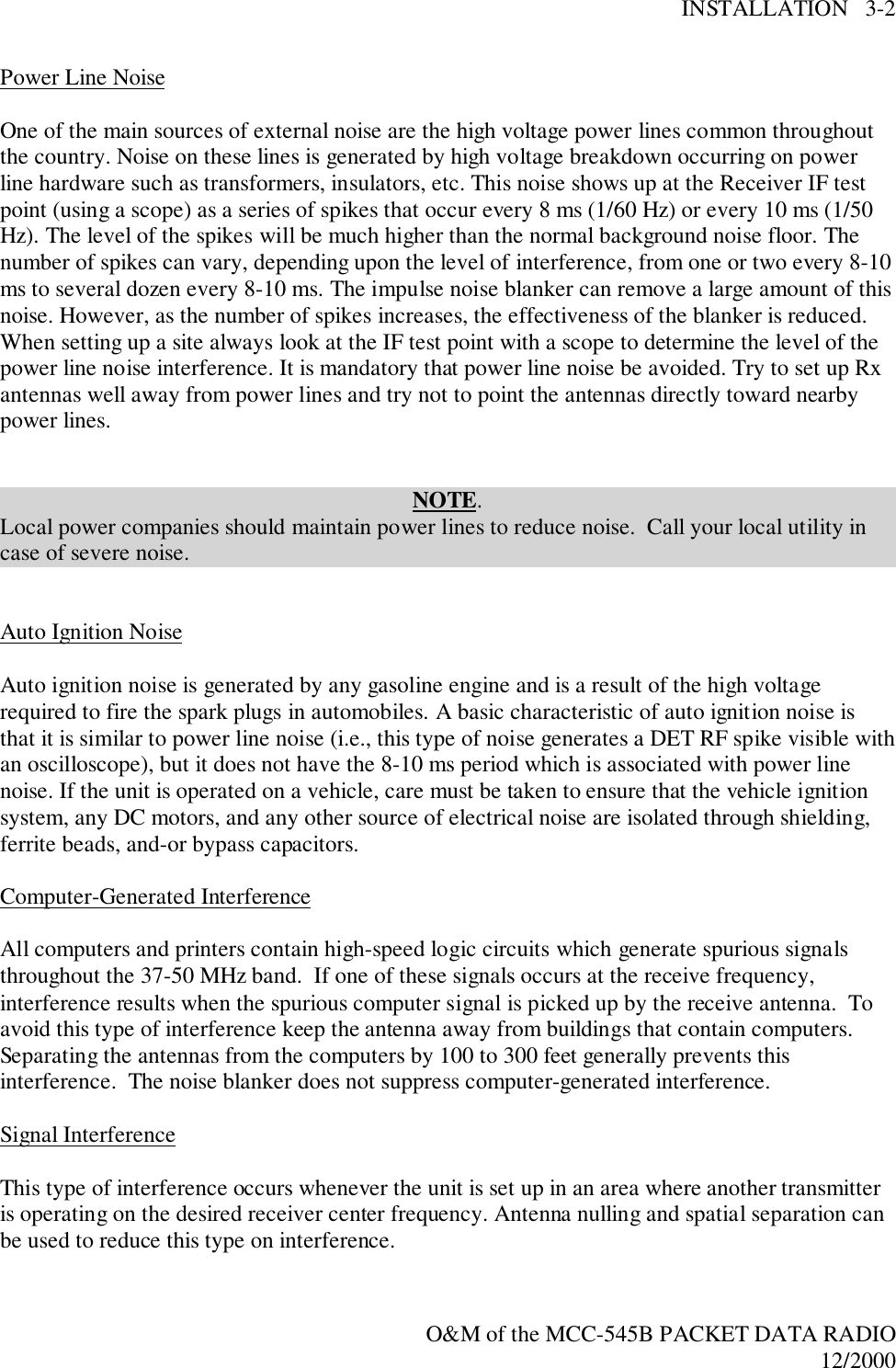
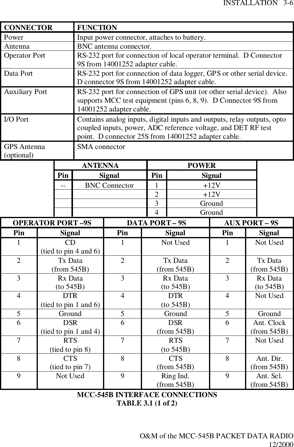
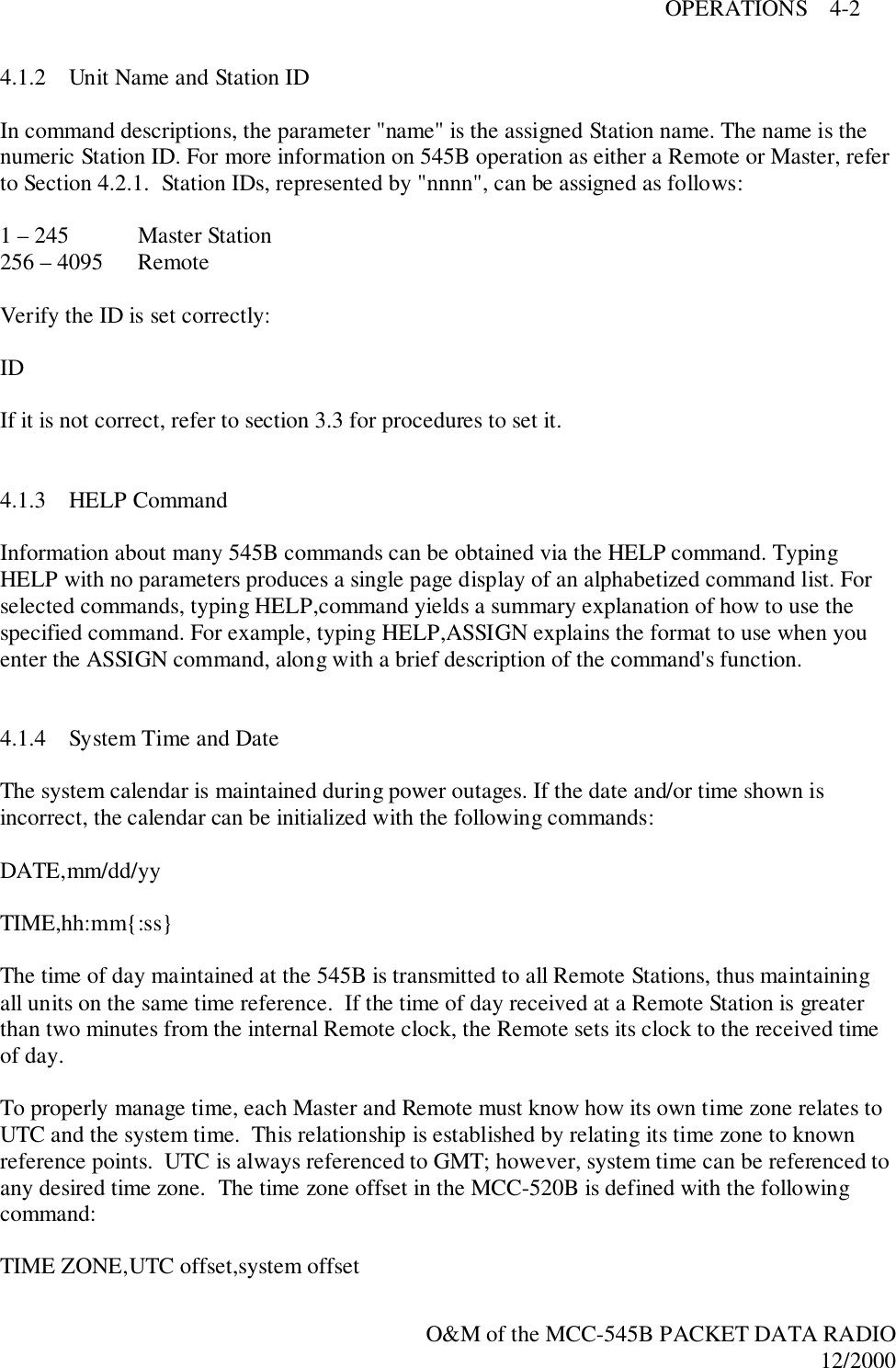
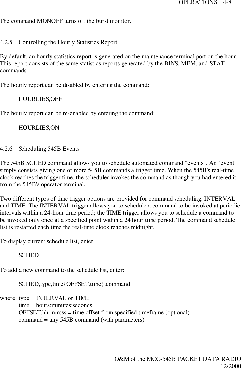
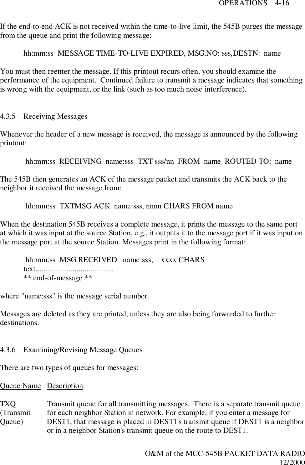
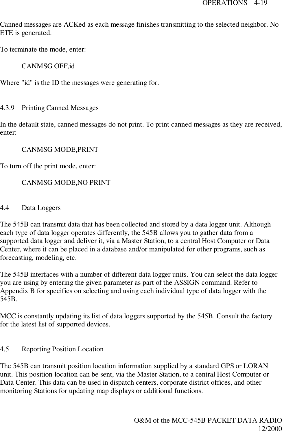
![OPERATIONS 4-1O&M of the MCC-545B PACKET DATA RADIO12/20004.0 OPERATIONSThis chapter covers the fundamental operating procedures and is functionally divided into sevensections:! Getting Started! Station Operational Parameters! Sending and Receiving Messages! Data Logging! Reporting Position Location! Master Mode Functions! Examining Systems Statistics4.1 Getting Started4.1.1 Command Entry and EditingYou must enter carriage returns after every command. A list of operator commands follows theoperating instructions (Table 4.2).When a command is accepted, the operator terminal prints the system time. For a description ofprintouts, see Appendix A.Before you begin, you should know about the special editing functions that you can use whenentering commands:[DEL] Deletes last character entered.[CTRL] Prints command line on next line down.[CTRL]-R Repeats last command line\X Removes current line from command buffer.[CR] Terminates line and causes command entered to be executed. or[LF] or[ENTER]](https://usermanual.wiki/Meteorcomm/54506001-01/User-Guide-134278-Page-37.png)
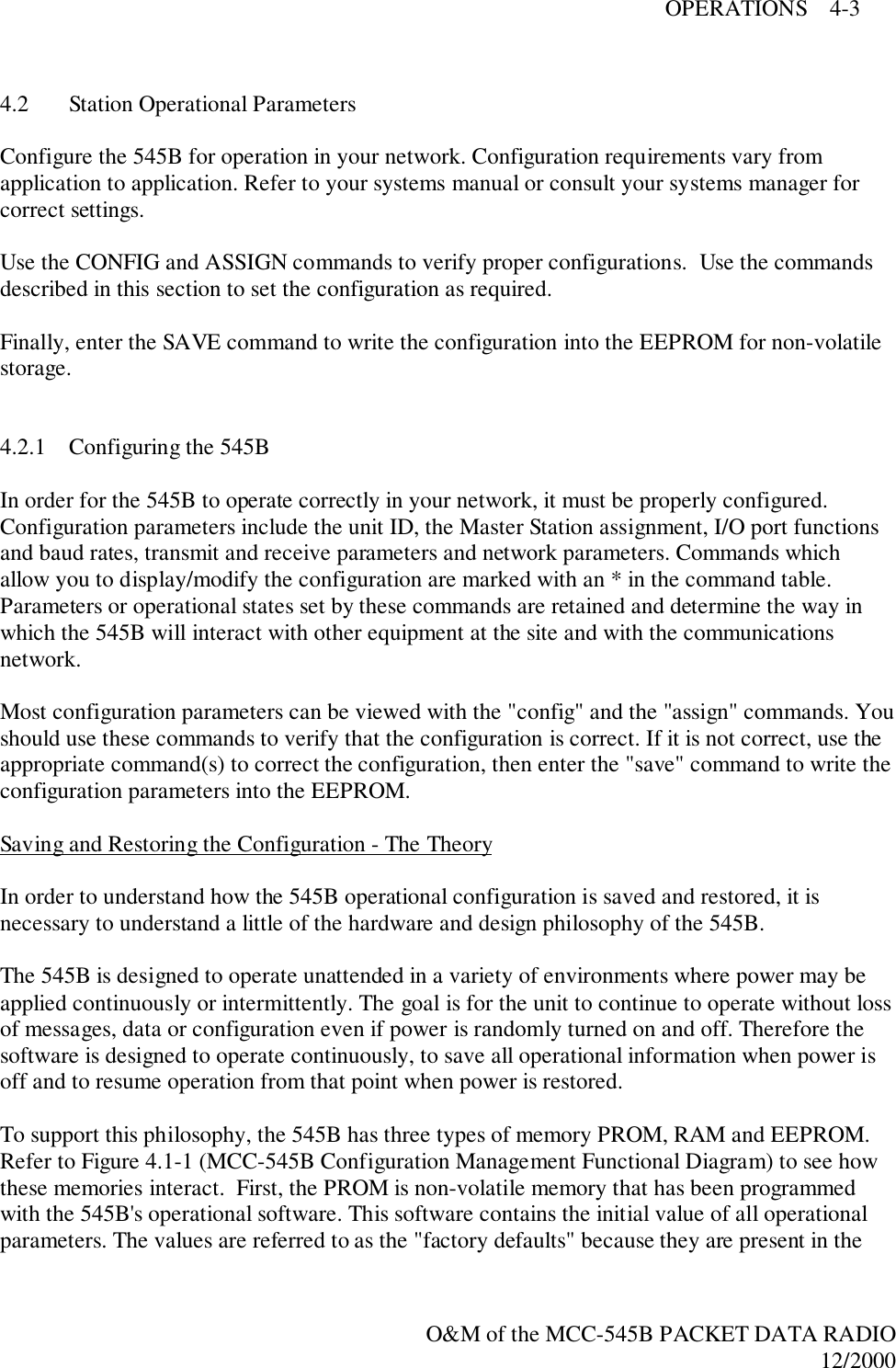
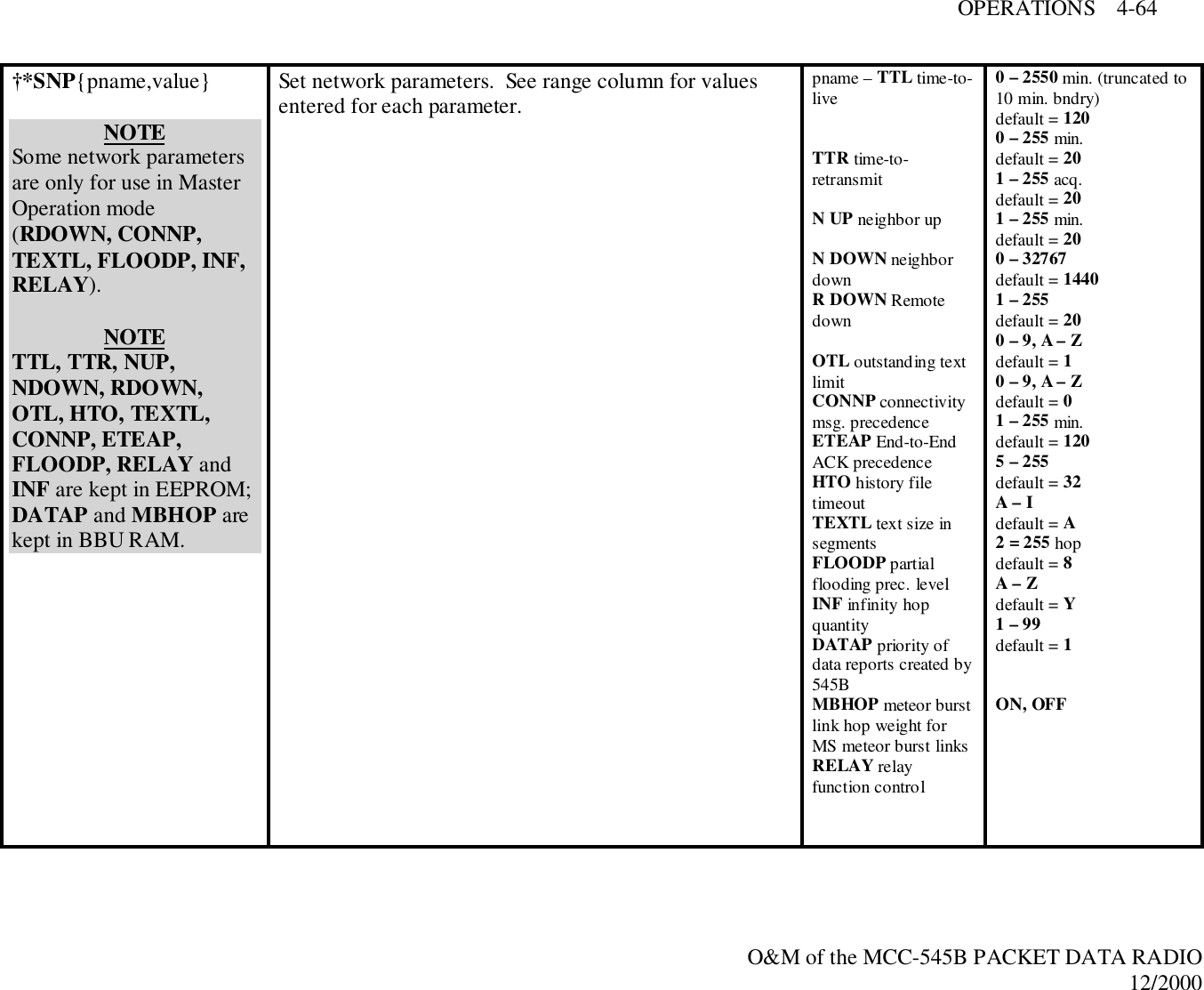
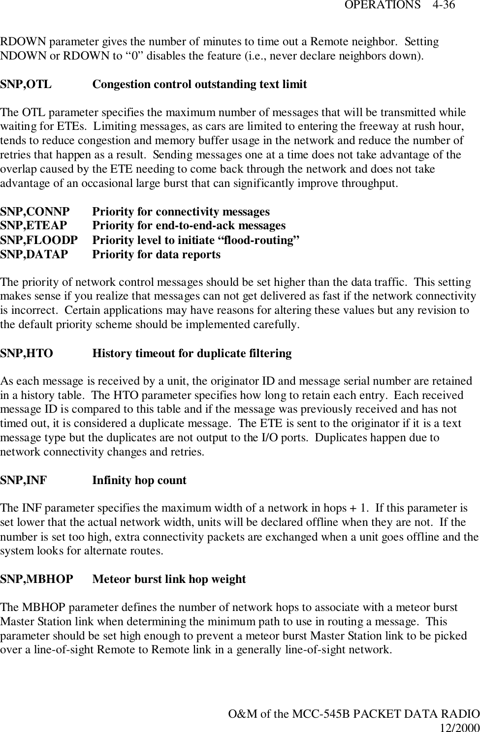
![OPERATIONS 4-6O&M of the MCC-545B PACKET DATA RADIO12/2000where "pname" is the network parameter, and "value" is a limit dependent on "pname". The"pname" parameters are as follows:TTL – time-to-live in minutes (default 120 minutes); i.e., the time limit for a message toreach its destination before it is deleted from the queue.The time-to-live parameter input is truncated to a 10-minute boundary forutilization by the 545B (e.g., if you enter 66 or 64, the TTL for the next messagestarts at 60). A resultant value of 0 (parameter range 0 – 9) means never time out.TTR – time-to-retransmit in minutes (default 20 minutes); i.e., the message isretransmitted if it has not reached its destinations in this time frame.NUP – neighbor-up threshold (default 20 acquisitions); the number of times a Stationmust hear from another Station in one minute before it becomes a neighbor.NDOWN – neighbor-down threshold in minutes (default 20 minutes); if there is nocommunication with a neighbor Station within the set time, the route to thatneighbor is ignored. Setting NDOWN to 0 keeps a neighbor defined indefinitely.RDOWN – Remote-down threshold in minutes (default 1,440 minutes); if there is nocommunication with a Remote Station within set time, the Remote is declareddown and is removed from the Remote table. Setting RDOWN to 0 keeps aRemote defined indefinitely. (MASTER OPERATION ONLY)OTL – outstanding text limit (default 20 texts); the number of messages a Station isallowed to send to another Station without an end-to-end acknowledgment.CONNP – connectivity message precedence (default 1 precedence); information on changesin the connectivity table is given highest precedence (automatic feature).(MASTER OPERATION ONLY)ETEAP – end-to-end ACK message precedence (default 0 [zero] precedence); theacknowledgment of a message when it reaches its final destination is givenhighest precedence.HTO – history file timeout in minutes (default 10 minutes); maintains information forduplicate filtering.TEXTL – text size in segments (default 32 segments). (MASTER OPERATION ONLY)FLOODP – partial "flooding" precedence level (default A precedence). Messages of thisprecedence level and above are transmitted over all routes of minimum length;messages below this precedence are not sent over all minimum length routes, but](https://usermanual.wiki/Meteorcomm/54506001-01/User-Guide-134278-Page-42.png)
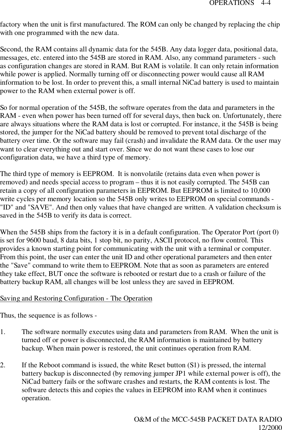
![OPERATIONS 4-12O&M of the MCC-545B PACKET DATA RADIO12/20004.3 Sending and Receiving Messages4.3.1 Entering and Deleting MessagesEntering MessagesThere are two ways to enter messages:1. If you want to send a message to your 545B's default destination (set with theDESTINATION command), enter the MESSAGE command with no parameters byfollowing these steps:a. Type MESSAGE. The computer enters the edit mode. If you decide to exit the editmode before transmitting a message, type [CTRL]A.b. Enter a message up to 3,570 characters in length, pressing [CR] at the end of each 80character line. To correct mistakes made upon entering the message, see Section4.3.3.c. After entering the message, press the [ESC] key. The [ESC] key queues the messagefor transmission.The computer prints the following message: hh:mm:ss Message No: name:sss, nnnn chars, nnn segments hh:mm:ss ROUTING name :sss TXT sss/nn TO: nameNOTEIf you want to use source routing, enter 0 for the destination ID. When the Master Stationreceives your message, it will send the message to the appropriate destination, based on its linktable showing which destination(s) are linked with your Station (the source Station where themessage was sent from). Refer to the Master Station manual for more information on sourcerouting.Messages entered in this fashion have a priority of R. If you want to send a message with ahigher (or lower) priority to your default destination Station, enter MESSAGE,p where "p" is anyletter A (top priority) to Z (lowest priority). If you also want to send the message to anotherStation, refer to step 2 following.2. If you want to send a message to another Station in addition to or instead of your defaultdestination, enter the MESSAGE command with priority and destination parameters byfollowing these steps:a. Type: MESSAGE,p,dest1,dest2...](https://usermanual.wiki/Meteorcomm/54506001-01/User-Guide-134278-Page-48.png)
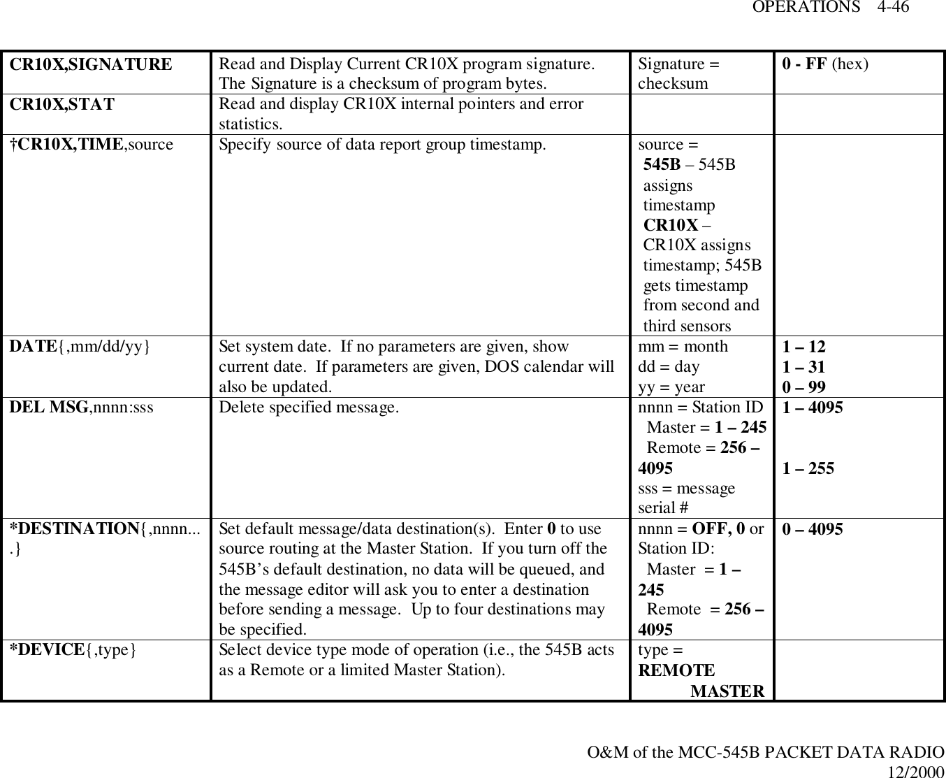
![OPERATIONS 4-13O&M of the MCC-545B PACKET DATA RADIO12/2000where "p" is any letter from A to Z (A is top priority, and Z is the lowest priority).When you enter the message destinations as command parameters ("dest1", "dest2", etc.),the message is automatically routed to those Stations when you enter the message andpress [ESC]. Destination is the Station numerical ID..NOTEIf you also want to send a copy of the message to your default destination, you must enter itsStation numerical ID as one of the command parameters ("dest1", "dest2", etc.) as specifiedabove.b. Enter a message up to 3,570 characters in length, pressing [CR] at the end of each 80character line. To correct mistakes made upon entering the message, see Section 4.3.3.c. After entering the message, press the [ESC] key. The [ESC] key queues the message fortransmission.The computer prints the following message: hh:mm:ss Message No: name:sss, nnnn chars, nnn segments hh:mm:ss ROUTING name :sss TXT sss/nn TO: nameSpecial Features1. Retransmit a Previously Entered Message.You can resend the previous message by simply pressing [ESC] before any other keywhen the terminal prints ENTER TEXT. The message is sent to any destination(s) youentered when you typed MESSAGE, or to the default destination if you did not enter anydestinations.2. Revise a Previously Entered Message.You can add to the previous message or recover an abort by typing a [CTRL]T as the firstcharacter after the ENTER TEXT: prompt. The previous message prints, and leaves thecursor at the end of the message. You can now resume editing; press [ESC] to send themessage, or [CTRL]D to erase the message.Deleting MessagesTo delete a message once you have placed it on-the-air (maintenance terminal only), type:DEL MSG,id:sss](https://usermanual.wiki/Meteorcomm/54506001-01/User-Guide-134278-Page-49.png)
![OPERATIONS 4-14O&M of the MCC-545B PACKET DATA RADIO12/2000where: id - numerical Station ID sss - message serial numberThe maintenance terminal prints the date and time, followed by MESSAGE DELETED. Othercommands that you can enter to delete messages are described in Section 4.3.6. See Appendix Afor a description of the printouts.4.3.2 Sending Commands to Remote StationsCommands may be sent to any Remote Station, in the form of text messages. The commandsmay be any valid command for that type of Remote, except for message entry. The response textfor the command is transmitted back to the 545B in the form of command response packets, andit is displayed on both the console and alternate console ports. The command entry is similar tothe MESSAGE command, which is shown in the Section 4.3.1.To send a command to a Remote, enter the following:REMCMD,p,dest1,...destnwhere: p - the priority character A to Z dest1...destn Remote numeric IDThe operator is prompted for the text of the single command to be entered using the messageeditor. Once the command is entered, press the [ESC] key to send the command. The operatorterminal prints:Hh:mm:ss Message No: name:sss, nnnn chars, nnn segments Master ID number of 14-character segments Message Number number of characters (0 – 255)The message is enqueued as a type CMD (as displayed by the SMS command). The response is atype MON message.4.3.3 Editing MessagesThere are several keys on the maintenance terminal that provide editing functions while thecomputer is in the edit mode. If you have left the edit mode by pressing the [ESC] key, you canfurther edit the message by typing MESSAGE, then [CTRL]T. The contents of the message youhave just entered is displayed. You can then edit the message using the following keys:](https://usermanual.wiki/Meteorcomm/54506001-01/User-Guide-134278-Page-50.png)
![OPERATIONS 4-15O&M of the MCC-545B PACKET DATA RADIO12/2000[DEL] Deletes the last character entered.[CTRL]R Prints the current line of text on the next line down.[CTRL]I Performs a fixed tab function.\ Removes the current line from the edit buffer.[CR] Performs a carriage return and line feed.[LF] Performs a carriage return and line feed.[CTRL]X Removes the current line from the edit buffer and places the cursor at the end ofthe previous line.[CTRL]T Prints the contents of the edit buffer.[CTRL]D Erases the entire contents of the edit buffer.[CTRL]A Aborts the edit mode and returns to the command mode. A + indicates the command mode.[ESC]B Leaves text edit mode and queues message for transmission.4.3.4 Transmitting MessagesYou automatically transmit messages by entering messages with the MESSAGE command. Eachmessage is placed in the transmit queue in order by assigned priority - messages of equal priorityare placed in the queue in the order that you enter it. As the originating 545B begins to transmitthe message, it prints the following message on the maintenance terminal:hh:mm:ss Message No: name:sss, nnnn chars, nnn segmentshh:mm:ss ROUTING name :sss TXT sss/nn TO: nameMessages are transmitted in units called packets. Packets can be independently routed to thedestination Station. When the next Station receives a message packet, you see anacknowledgement text line formatted as:mm/dd/yy hh:mm:ss TXTMSG ACK name:sss, xxxx CHARS FROM nameWhen the message has been delivered to its destination, you will see an end-to-endacknowledgement:hh:mm:ss END-TO-END ACK OF name:sss FROM name](https://usermanual.wiki/Meteorcomm/54506001-01/User-Guide-134278-Page-51.png)
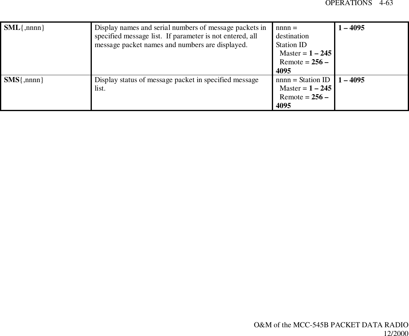
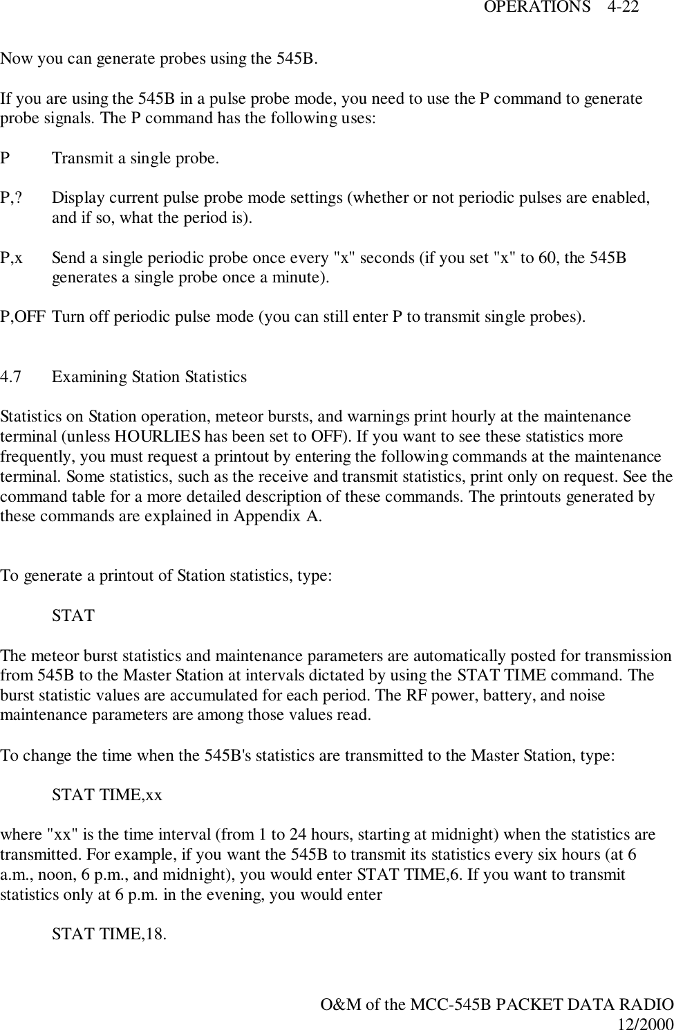
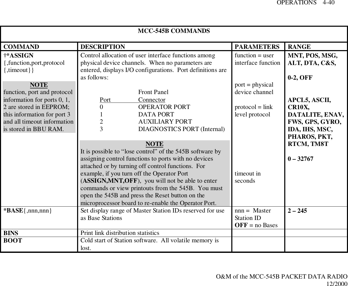
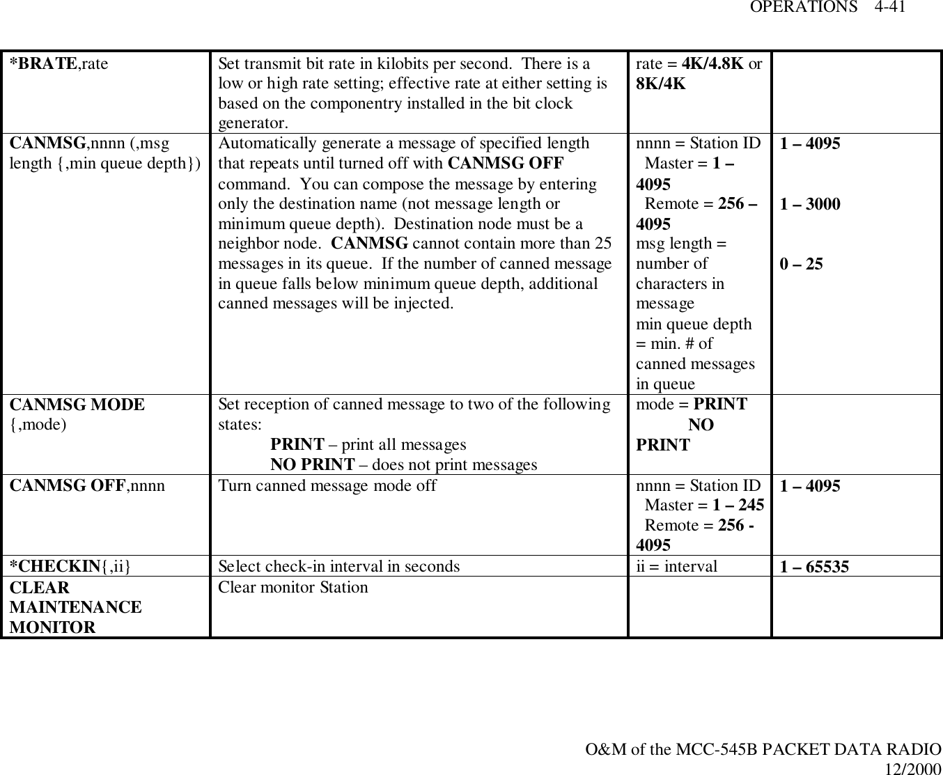
![OPERATIONS 4-18O&M of the MCC-545B PACKET DATA RADIO12/2000Entering the FLUSH MSG command deletes all messages in all queues for every node of thenetwork, including connectivity and end-to-end acknowledgment messages.4.3.7 Examining Message StatusThe software allows the user to examine message status. These commands display data only foryour Station. Since the message queues are dynamic, this information constantly changes. Aftermessages have been transmitted to their destinations (i.e., ETEs have been received by theoriginating Station), the messages are deleted from the queues.To see message status, enter "show message status":SMS{,id}These commands accept wild cards for parameters; i.e, a "*" replaces one character of text, and a"-" replaces any number of characters. Since received messages are deleted after they arecompletely transferred and printed, the "show message" command does not affect receive queue.See Appendix A for a description of printouts.4.3.8 Entering Canned MessagesYou can put the 545B into canned message mode, and it automatically generates messages fortransmission to an assigned neighbor until you terminate the mode. Canned message modecannot have more than 25 messages in the queue at one time. You can either send a message thatyou have composed, or you can send a message that is generated from the alphabet.To enter a canned message generated from the alphabet, enter:CANMSG,id,msg length{,min. queue depth}where "id" is your neighbor's Station ID, the message length is from 1 to 3000 characters, andthe minimum queue depth is from 1 to 25. The default minimum queue depth is 5. If the numberof canned messages in the queue falls below the minimum queue depth, additional cannedmessages are injected.To enter a canned message that you compose, enter:CANMSG,idwhere "id" is your neighbor's Station ID. The Station puts you in the edit mode. Compose yourmessage and press [ESC]. The Station routes one canned message, then generates up to 25messages. After the messages are generated, they are routed in sequence to the destinationStation.](https://usermanual.wiki/Meteorcomm/54506001-01/User-Guide-134278-Page-54.png)
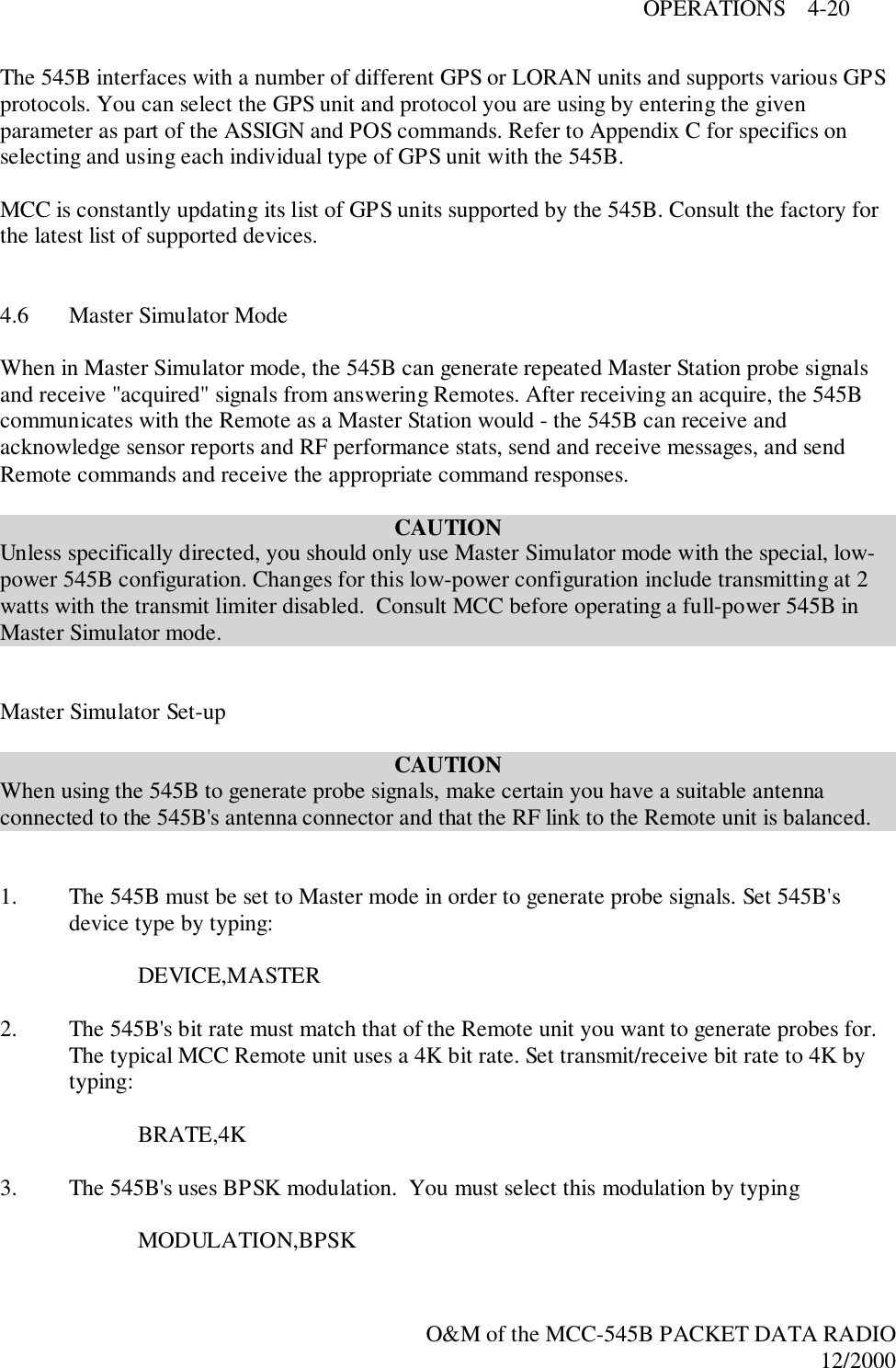
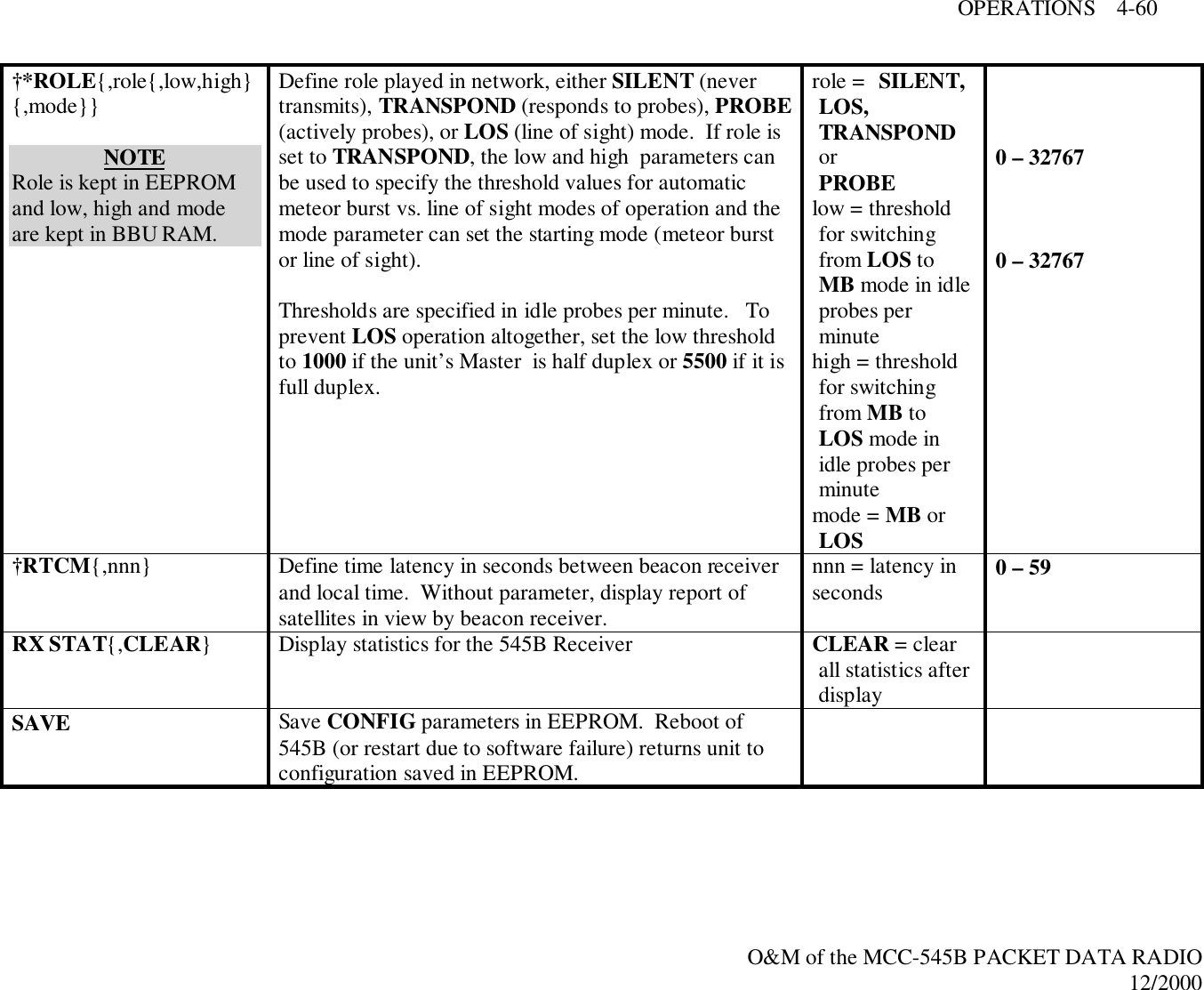
![OPERATIONS 4-21O&M of the MCC-545B PACKET DATA RADIO12/20004. The 545B must transmit in half-duplex mode, due to its built-in T/R switch. Set transmitmode to half-duplex by typing:HALFDUPLEXIMPORTANTThe 545B cannot communicate using full-duplex mode. If you place the 545B in full-duplexmode (in order to simulate a full-duplex Master), the 545B's receiver is disabled by the built-inT/R switch.The 545B can use two different "roles" when generating probe signals (see also the explanationof the P command following step 6).If you want to generate repeated probe signals (like a Master Station's "idle" or enquireprobe), set 545B role to probe by typing:ROLE,PROBEIf you only want to produce single pulse probes (for testing an individual Remote'sresponsiveness), or to probe very slowly, set 545B role to transpond by typing:ROLE,TRANSPONDOptionally, you can set the low and high threshold numbers for determination of LOSoperation when setting ROLE to TRANSPOND and/or the initial state of the mode (MBor LOS). When operating in the LOS mode, the 545B waits a random number of idleprobes between each probe.6. The 545B's ID must match the assigned Master ID for the Remote unit(s) being probed.Set ID by typing:ID,n,INITwhere "n" is the assigned Master ID of the Remote unit.IMPORTANTIf you change the 545B's ID, the software reboots after you enter the INIT parameter and press[CR]. The SAVE command is automatically performed, ensuring that your configurationchanges are kept in EEPROM (and not lost after power cycling). However, if you do not need tochange the 545B's ID (i.e., it was already set to the same ID as the Remote unit's assignedMaster), make certain you use the SAVE command before starting to probe or any configurationchanges you have made will be lost if the 545B is rebooted.](https://usermanual.wiki/Meteorcomm/54506001-01/User-Guide-134278-Page-57.png)
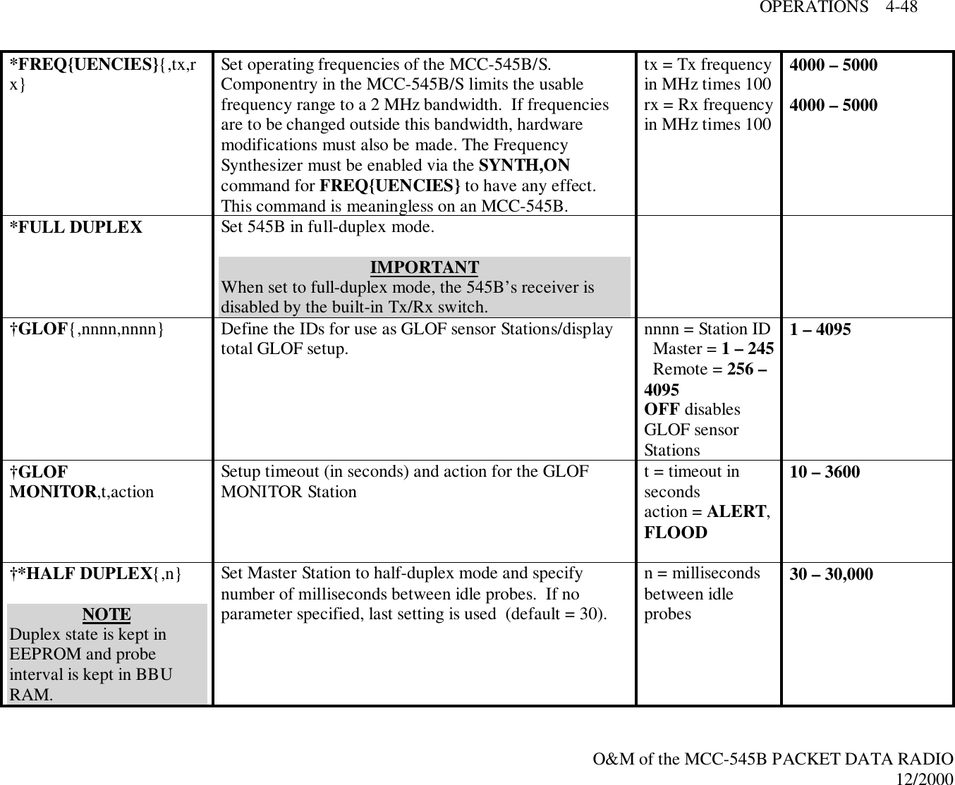
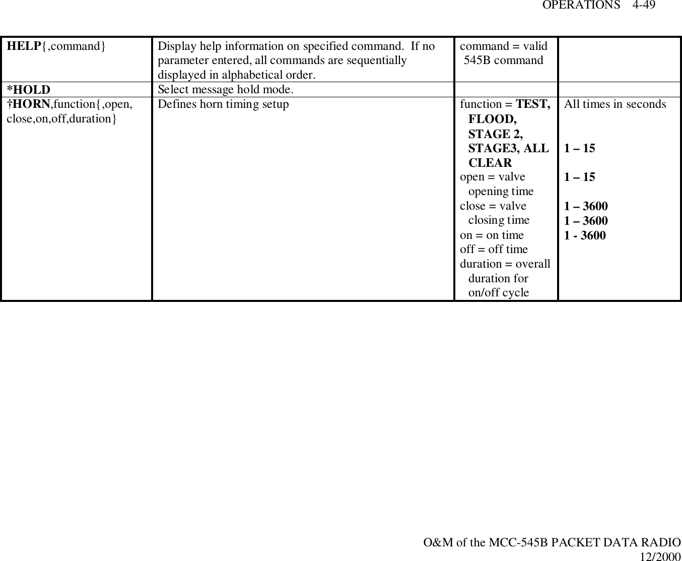
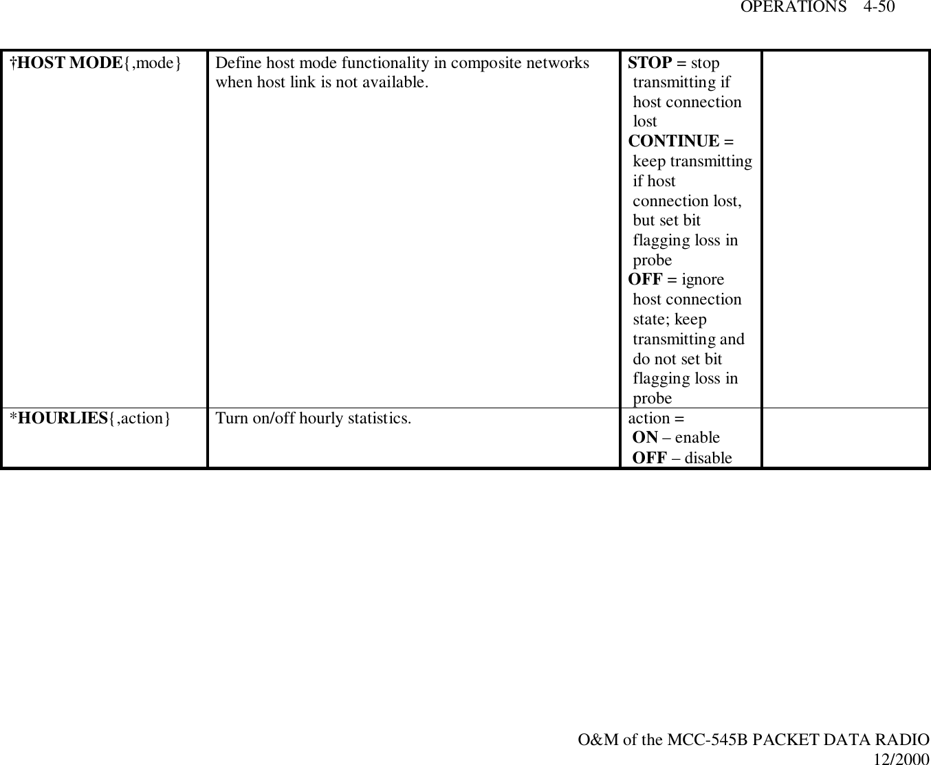
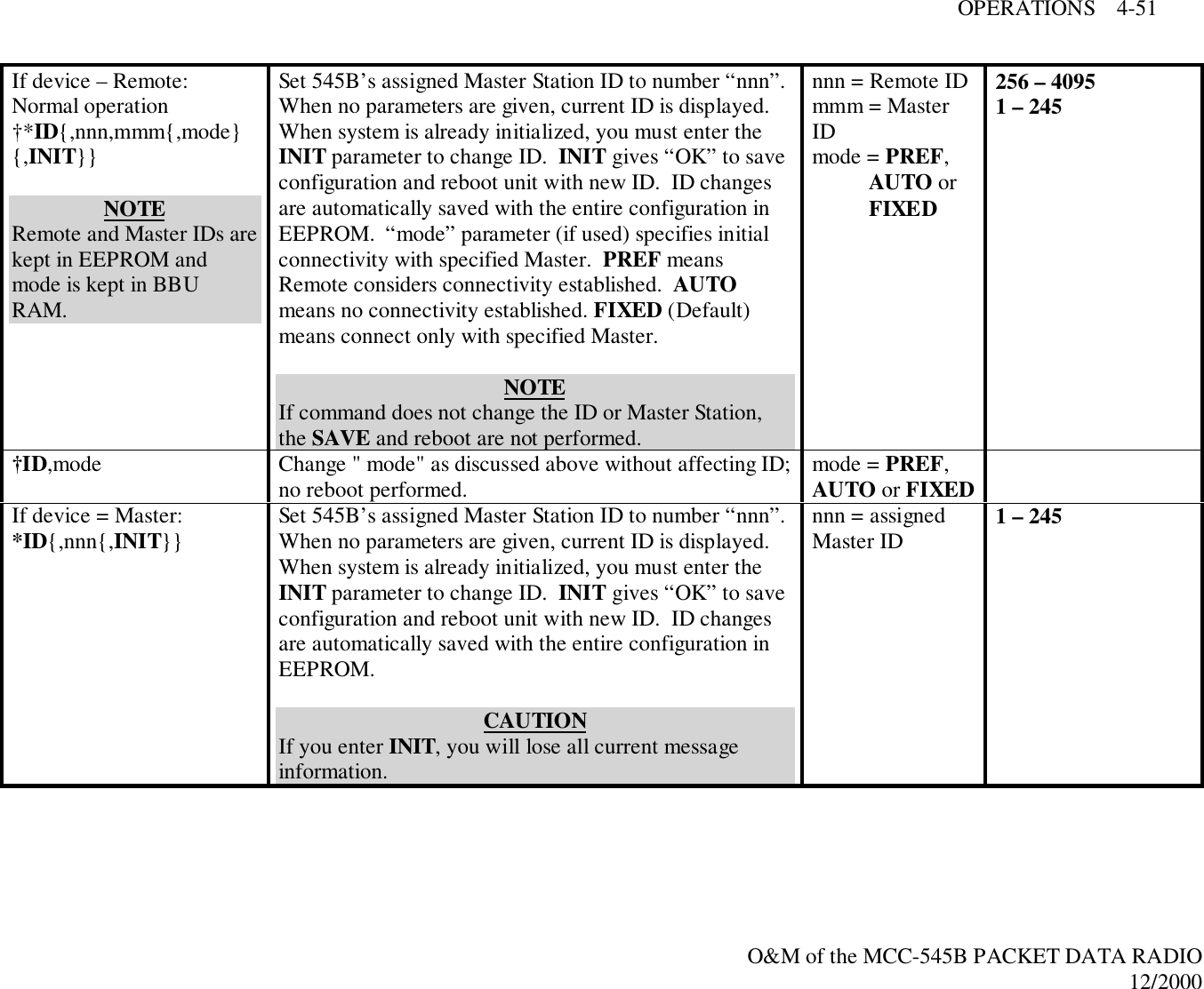
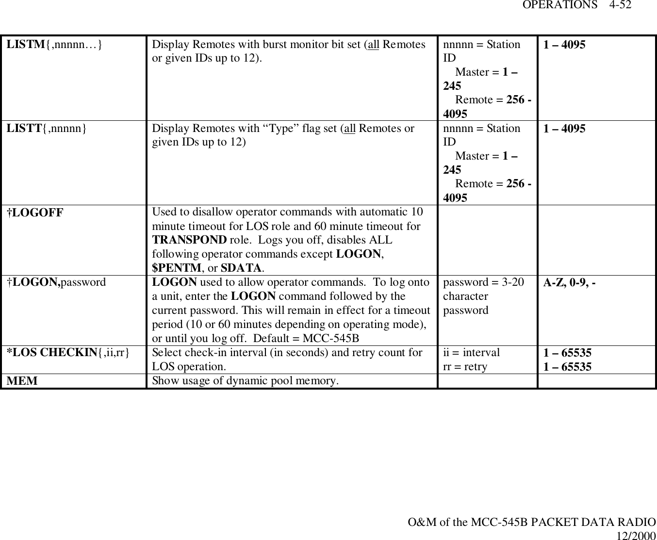
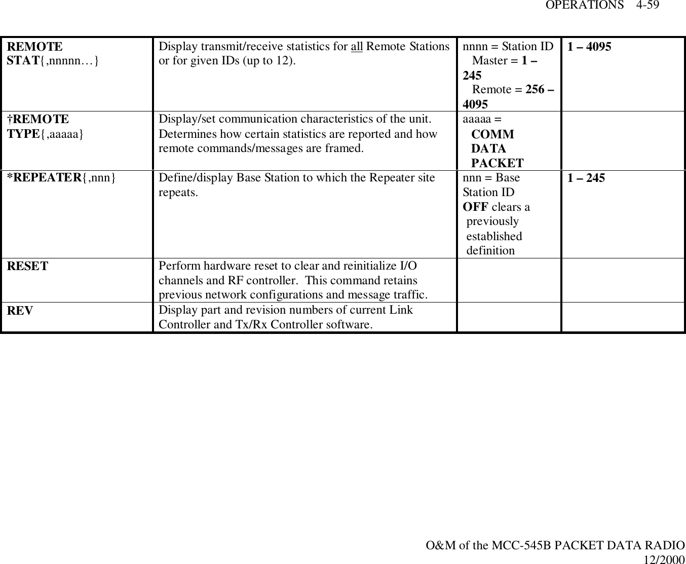
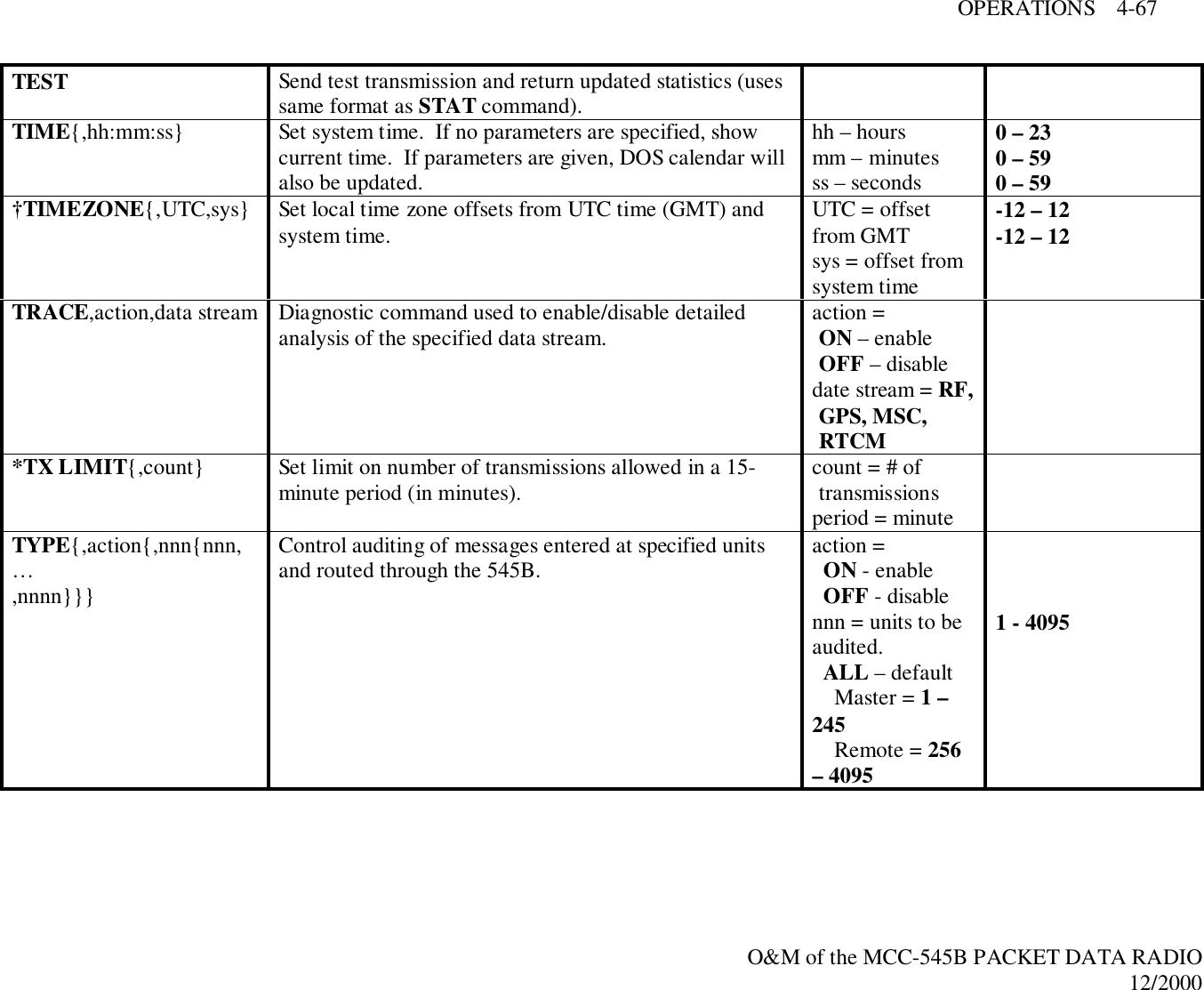
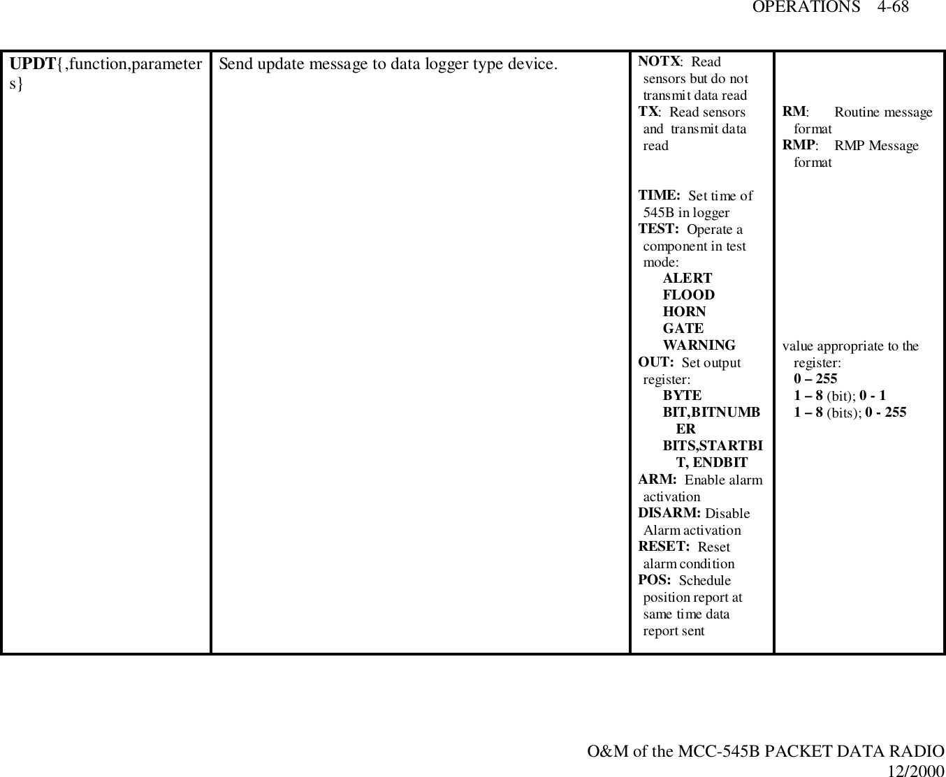
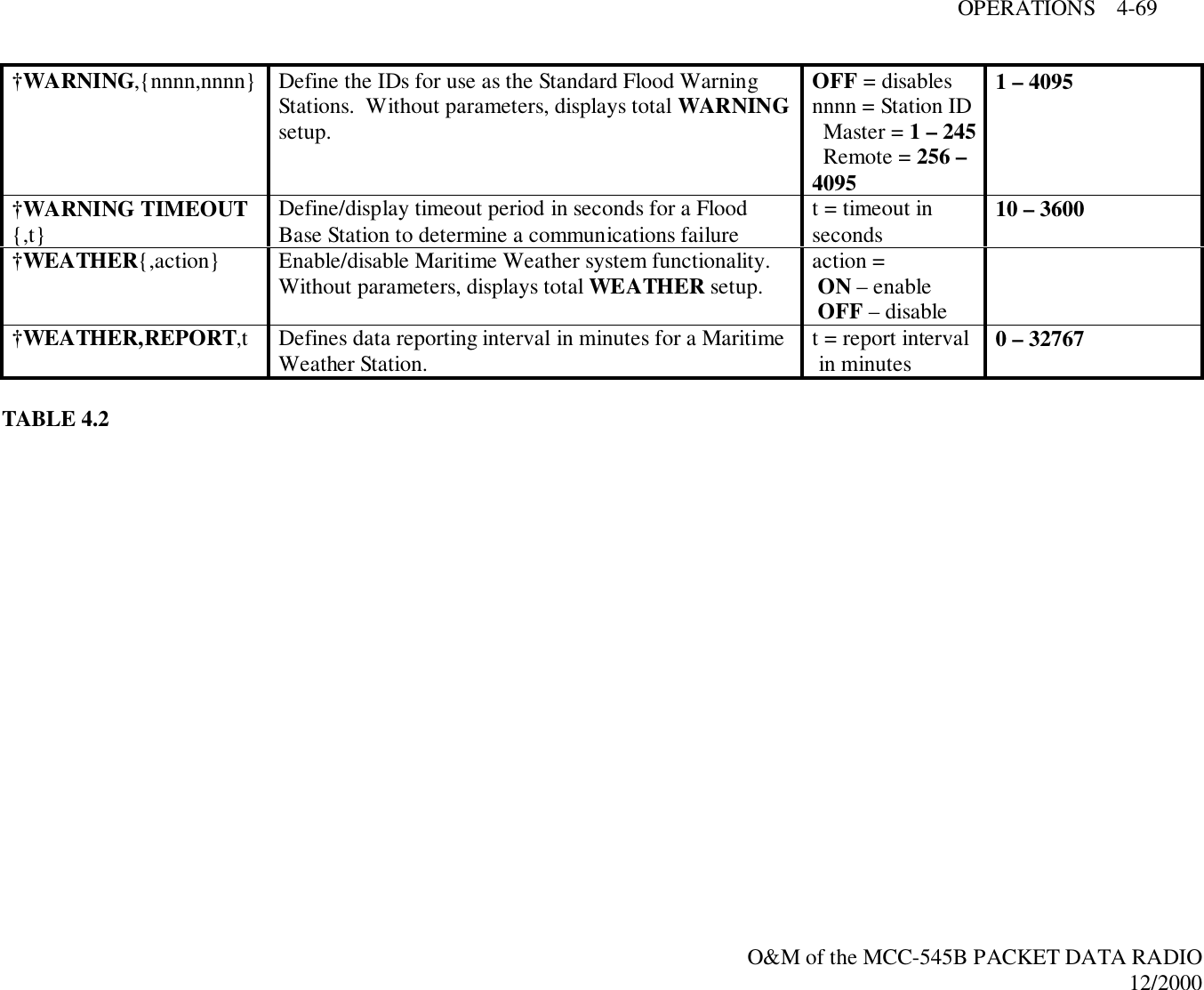
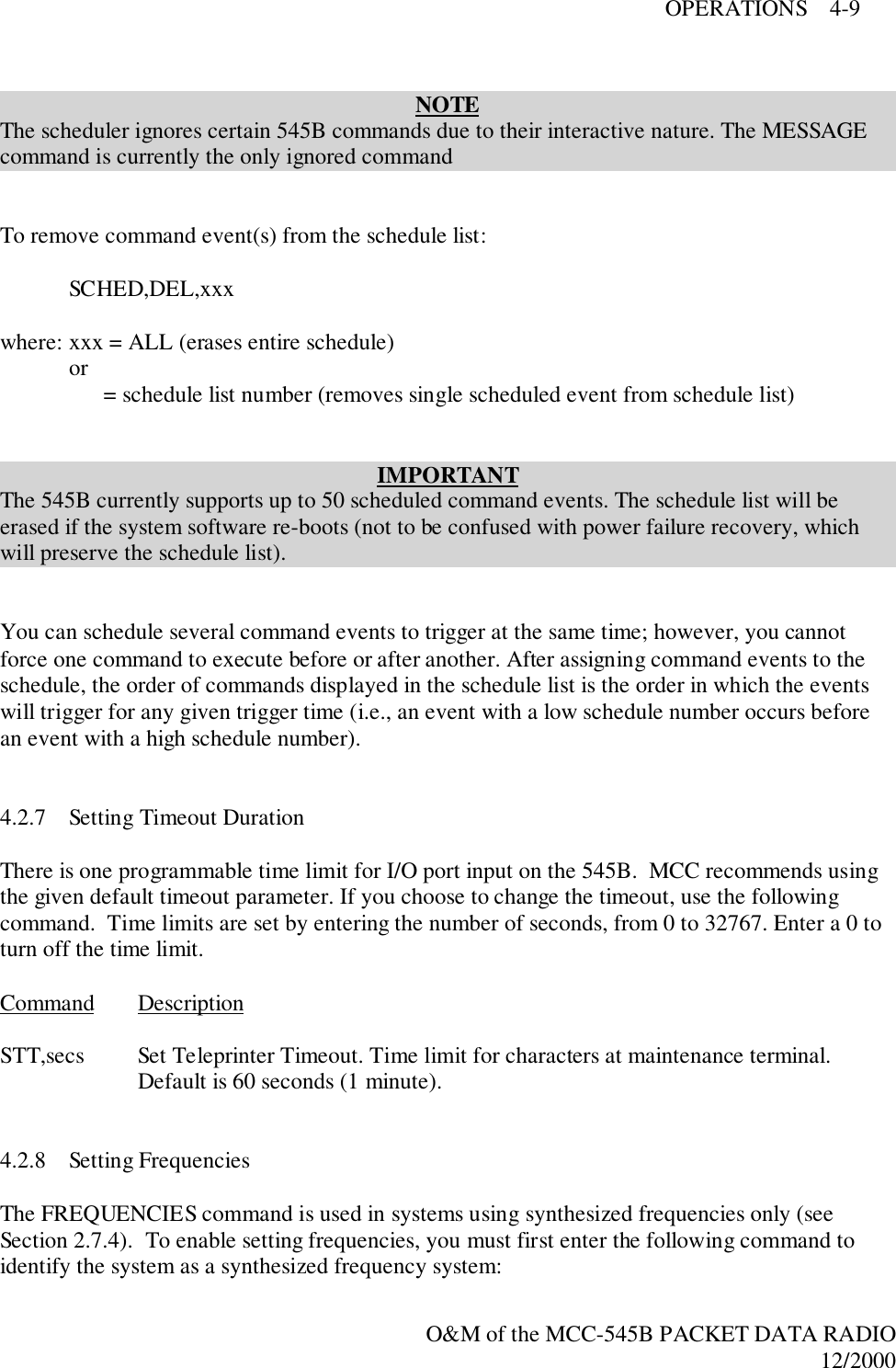
![OPERATIONS 4-53O&M of the MCC-545B PACKET DATA RADIO12/2000MESSAGE{,p{,dest1…destn}} Enter a message with text editor. Message priority anddestination are optional parameters. After enteringmessage, press [ESC] to queue for transmission. If youdo not enter a destination ID, the 545B automaticallysends your message to its default destination (set with theDESTINATION command). If you want to use sourcerounting, enter 0 for the destination.p = prioritydest1. . .destn =destination(s)name = nodenamennnn = Station ID Master = 1 –245 Remote = 256 –4095A – Z, 0 – 9A – Z, 0 – 91 – 4095MM Print current value of RF signal on ReceiverMODE Print operating mode information.*MODULATION,degree,encoding Set the transmit modulation and data encoding.IMPORTANT545B modulation must be the same as other units in thenetwork.degree = 90 or 30encoding = MANfor Manchester,DIFF fordifferential†MON{,d{,r}} Turn on burst monitor. Only meteors lasting longenough to deliver “d” characters will be monitored. If atleast “r” characters were received, a monitor line isgenerated.d = durationcharacter countlimitr = receivedcharacter countlimit0 – 327670 – 32767MONITOR{action{,nnn{,nnn,…,nnn}}} Control monitoring of individual units and print burststatistics. Overrides MONOFF command and causesmonitor lines to print for each reception from this unit.action = ON – enable OFF – disablennn = units to bemonitored ALL – default Master = 1 –245 Remote = 256 -40951 - 4095](https://usermanual.wiki/Meteorcomm/54506001-01/User-Guide-134278-Page-89.png)
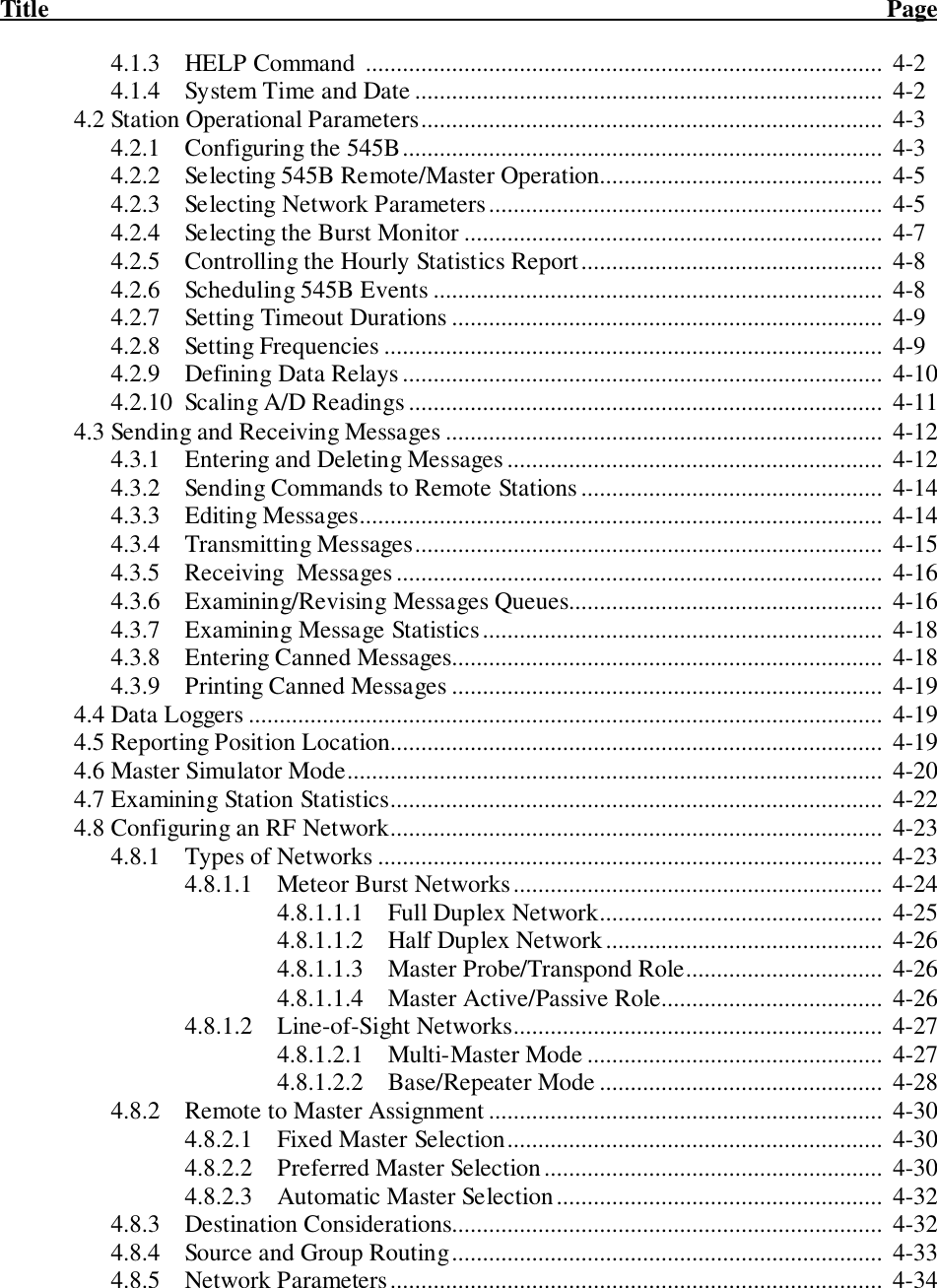
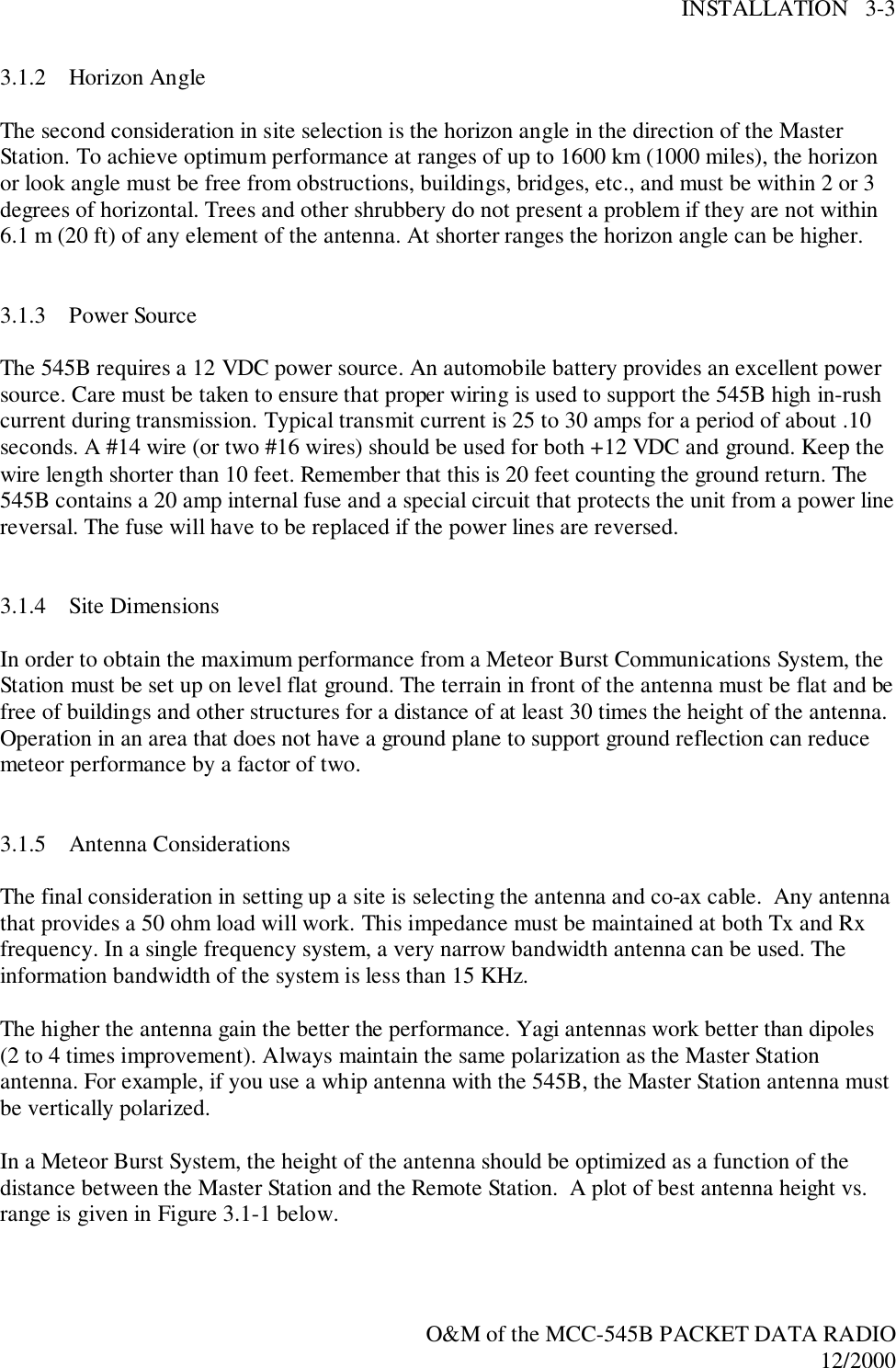
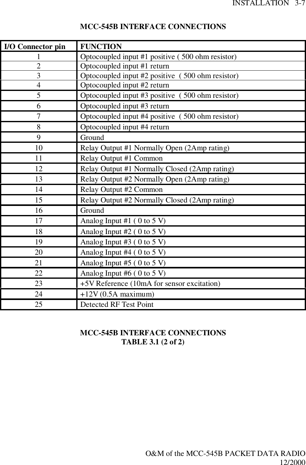
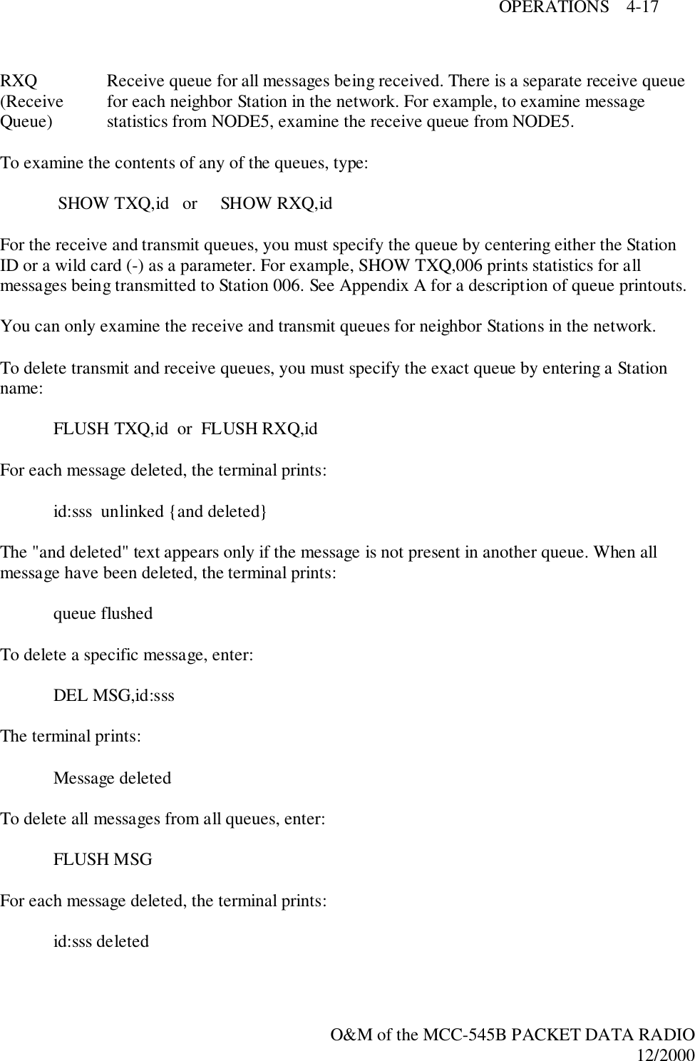
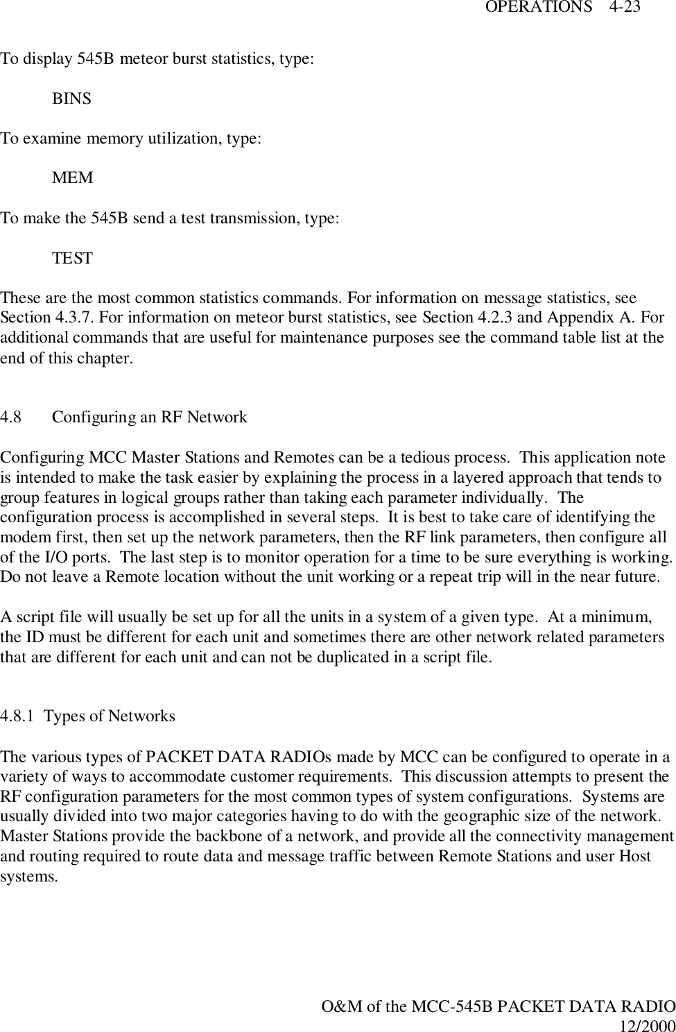
![OPERATIONS 4-58O&M of the MCC-545B PACKET DATA RADIO12/2000†RCT{,action} Display/set remote control terminal functionality. Thisfunctionality is applicable to Packet protocol systemsonly and controls whether the unit ignores intercepteddata reports. If enabled, intercepted reports are ignored.action = ON – enable OFF – disableRED Without parameters, generates report of current REDsetup.†RED,ID,nn-nnn Enables reception of remote emergency indications froman MCC Remote Emergency Device (RED). The enteredID code is used with RED messages generated by the545B using RED,TEST or RED,TX.nn = call signprefixnnn = call signsuffix0 – 990 – 999†RED,NUM,n Set dead-band interval in which repeated REDactivations do not generate another alert message. n = dead-bandinterval inseconds1 – 120†RED,OFF Disable reception of remote emergency indications froman MCC Remote Emergency Device (RED).RED,TEST Simulate a RED test message. Unlike a true RED testbutton depression, this message is also echoed to thelocal MNT and DTA ports.RED,TX Simulate a RED alert message. Unlike a true RED alertbutton depression, this message is also echoed to thelocal MNT and DTA ports.REMCMD,p,dest1{,…destn} With the text editor, enter a command to be sent to aRemote. After entering command, press [ESC] to sendthe command.p = prioritydest1…destndestination(s) name = nodename nnnn = StationID Master = 1 –245 Remote = 256 –4095A – Z, 0 – 9A – Z, 0 – 91 – 4095](https://usermanual.wiki/Meteorcomm/54506001-01/User-Guide-134278-Page-94.png)