Metocean Data Systems MMB1000 Miniature VHF Radio Beacon User Manual
Metocean Data Systems Miniature VHF Radio Beacon
User Manual
NovaTech Beacons & Flashers
Mini-Beacon 1000
VHF Radio Beacon
Operation & Maintenance Manual
TD 12-024
Mini-Beacon 1000
Operation & Maintenance Manual
January 2012
TD 12-024 Version 1.1
© METOCEAN DATA SYSTEMS | All Rights Reserved
© 2012 by MetOcean Data Systems, All Rights Reserved. This manual may not
be reproduced in any way without written permission of MetOcean Data
Systems.
Information contained in this manual is subject to regular updates and changes.
MetOcean Data Systems may have patents, patent applications, trademarks,
copyrights, or other intellectual property rights covering subject matter in this
document. Except as expressly provided in any written license agreement from
MetOcean Data Systems the furnishing of this document does not give the user
any license to these patents, trademarks, copyrights, or other intellectual
property.
Mini-Beacon 1000
Operation & Maintenance Manual
January 2012
TD 12-024 Version 1.1
© METOCEAN DATA SYSTEMS | All Rights Reserved
Table of Contents
1 Safety Information ................................................................................................................................. 1
1.1 Pressure Case............................................................................................................................... 1
1.2 Unauthorised Modifications ........................................................................................................... 1
1.3 Class B Digital Device Compliance ............................................................................................... 1
2 Introduction ............................................................................................................................................ 2
3 Quick Start ............................................................................................................................................. 3
4 Installation ............................................................................................................................................. 4
4.1 Antenna ......................................................................................................................................... 4
4.2 Pressure Case............................................................................................................................... 4
5 Operating Instructions ........................................................................................................................... 5
5.1 On/Off ............................................................................................................................................ 5
5.2 Batteries ........................................................................................................................................ 5
5.3 Test Operation............................................................................................................................... 6
5.4 Direction Finding Receiver ............................................................................................................ 6
5.5 Range ............................................................................................................................................ 6
6 Configuration Details ............................................................................................................................. 7
6.1 On/Off ............................................................................................................................................ 7
6.2 Daylight Off .................................................................................................................................... 8
6.3 RF Frequency................................................................................................................................ 8
6.4 RF Pulse Duration ......................................................................................................................... 9
6.5 Duty Cycle ................................................................................................................................... 11
7 Maintenance ........................................................................................................................................ 12
7.1 Regular Maintenance .................................................................................................................. 12
7.2 Battery Change ........................................................................................................................... 12
7.3 “O” Ring Facts ............................................................................................................................. 13
Mini-Beacon 1000
Operation & Maintenance Manual
January 2012
TD 12-024 Version 1.1
© METOCEAN DATA SYSTEMS | All Rights Reserved
7.4 “O” Ring Maintenance ................................................................................................................. 13
7.5 Corrosion Prevention .................................................................................................................. 13
8 Specifications ...................................................................................................................................... 14
9 Warranty .............................................................................................................................................. 15
List of Figures
Figure 1: Magnet Approaching and On Target ............................................................................................. 5
Figure 2: PCB Removed From Pressure Case ............................................................................................. 7
Figure 3: PCB Showing DIP Switch Locations............................................................................................ 10
Figure 4: PCB removed for battery change ................................................................................................ 12
List of Tables
Table 1: 4 Position DIP Switch ...................................................................................................................... 8
Table 2: 8 Position DIP Switch ...................................................................................................................... 9
Table 3: RF Frequency ............................................................................................................................... 10
Table 4: RF Frequency (7500A) ................................................................................................................. 10
Table 5: RF Pulse Duration ......................................................................................................................... 10
Table 6: Duty Cycle ..................................................................................................................................... 11

Mini-Beacon 1000
Operation & Maintenance Manual
January 2012
TD 12-024 Version 1.1
© METOCEAN DATA SYSTEMS | All Rights Reserved
Page 1
1 Safety Information
1.1 Pressure Case
As with any sealed pressure case, the contents could be under pressure due to a battery or seal failure.
This could expel the batteries when the device’s lens cap is removed. To be safe, always point the
antenna end cap away from you during opening. The antenna end cap is designed to vent internal
pressure as it is removed. If venting is heard during the caps removal, stop removal until venting has
stopped. If a battery is trapped in the case take extreme care, there could be a pressure buildup behind it
and the battery could be expelled at any time.
1.2 Unauthorised Modifications
Any changes or modifications made to this device or any of its accessories, which have not been
expressly approved by MetOcean Data Systems, may result in the user voiding their authority to operate
said equipment.
1.3 RF Exposure
WARNING: To satisfy FCC RF exposure requirements for mobile transmitting devices,
a separation distance of 20 cm or more should be maintained between the antenna of
this device and persons during the device operation. To ensure compliance,
operations at closed that this distance are not recommended. The antenna used for
this transmitter must not be co-located in conjunction with any other antenna or
transmitter.
1.4 Class B Digital Device Compliance
NOTE: This equipment has been tested and found to comply with the limits for a Class B digital device,
pursuant to part 15 of the FCC Rules. These limits are designed to provide reasonable protection against
harmful interference in a residential installation. This equipment generates, uses, and can radiate radio
frequency energy and, if not installed and used in accordance with the instructions, may cause harmful
interference to radio communications. However, there is no guarantee that interference will not occur in a
particular installation. If this equipment does cause harmful interference to radio or television reception,
which can be determined by turning the equipment off and on, the user is encouraged to try to correct the
interference by one or more of the following measures:
— Reorient or relocate the receiving antenna.
— Increase the separation between the equipment and receiver.
— Connect the equipment into an outlet on a circuit different from that to which the receiver is
connected.
— Consult the dealer for help
Mini-Beacon 1000
Operation & Maintenance Manual
January 2012
TD 12-024 Version 1.1
© METOCEAN DATA SYSTEMS | All Rights Reserved
Page 2
2 Introduction
The Mini-Beacon 1000 is a self-contained submersible Radio Beacon designed to assist in the location
and recovery of surface and subsurface oceanographic equipment. The Mini-Beacon 1000 may be
submerged to depths of 1,000 meters (3,280 feet).
The Mini-Beacon 1000 has 2 variants – 1000 and 1000A. MMB1000 provides 4 frequencies and 1000A
provides 2 additional frequencies, for a total of 6 frequencies available. These frequencies are in the
range of 154 MHz to 161 MHz. In standard configuration, the Mini-Beacon 1000 has the following preset
frequencies.
Channel A: 154.585 MHz
Channel B: 159.480 MHz
Channel C: 160.725 MHz
Channel D: 160.785 MHz
In the 1000A configuration, the following preset frequencies are available.
Channel A: 159.150 MHZ
Channel B: 159.200 MHZ
Channel C: Not Configured
Channel D: Not Configured
For the remainder of this manual, unless otherwise specified, the term 1000 will refer to both 1000 and
1000A.
The Mini-Beacon 1000 offers multiple user configurable options including daylight off option. Please refer
to section 7 for unit configuration details.
In standard configuration the Mini-Beacon 1000 produces a 2 second transmission on a 17% duty cycle.
The device will produce a pulsing, 17 dBm maximum, 154.585 MHz RF signal for approximately 25 days.
The device can be turned ON or OFF by triggering the internal magnetic reed switch.
Mini-Beacon 1000
Operation & Maintenance Manual
January 2012
TD 12-024 Version 1.1
© METOCEAN DATA SYSTEMS | All Rights Reserved
Page 3
3 Quick Start
1. The Mini-Beacon 1000 is shipped with batteries installed.
2. Open the device by disconnecting between pressure case and knurled feature on the antenna cap to
expose the Mini-Beacon 1000 PCB. Please refer to section 7 for assembly and disassembly details.
3. Position switch #1 on the 8 position DIP switch to the on position to apply power to the PCB.
4. Close the unit. The unit will default to the ON state following reassembly.
5. Turn on DF-500N Receiver or other receiver tuned to the correct frequency and check that there is a
pulsing signal.
6. The standard configuration Mini-Beacon 1000 is ready to be deployed. In standard configuration the
unit can be turned ON or OFF by triggering the internal magnetic reed switch. Please refer to section
6.1. Should you require configuration other than standard please refer to section 7 for unit
configuration details.
Mini-Beacon 1000
Operation & Maintenance Manual
January 2012
TD 12-024 Version 1.1
© METOCEAN DATA SYSTEMS | All Rights Reserved
Page 4
4 Installation
Various installation factors can affect the performance of the Mini-Beacon 1000. Install the unit in a
location that will ensure that when the beacon is at the sea surface the antenna will be vertical and well
out of the water. Keep the antenna well clear of metal obstructions. Nearby metal can absorb some of
the R.F. energy, reducing the range.
4.1 Antenna
The Mini-Beacon 1000 is supplied with one ¼ wave low profile antenna, part number K00172. Install the
antenna on the stud located on the top of the antenna cap and secure finger tight only – do not use a
wrench.
4.2 Pressure Case
When mounting the pressure case take care to prevent any side loading on the antenna cap. Side
loading on this cap could cause damage resulting in reduced performance or leakage.
To minimize possibility of corrosion or wear, NEVER mount the pressure case directly to metal. Isolate
the pressure case by wrapping it with vinyl tape, or similar, at the contact points.
Mini-Beacon 1000
Operation & Maintenance Manual
January 2012
TD 12-024 Version 1.1
© METOCEAN DATA SYSTEMS | All Rights Reserved
Page 5
5 Operating Instructions
5.1 On/Off
Power to the Mini-Beacon 1000 PCB can be controlled by placing switch #1 on the 8 position DIP switch
in the on or off positions. See Table 2: 8 Position DIP Switch and Figure 3: PCB Showing DIP Switch
Locations.
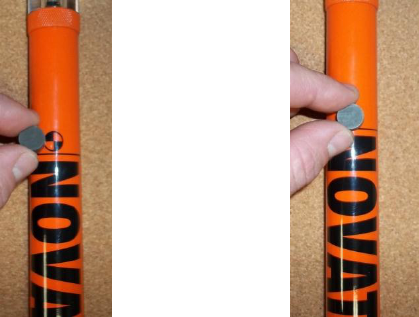
The device may be turned ON or OFF by actuating the magnetic reed switch, located within the pressure
case, with an externally placed magnet.
The magnet must be held in position until you have confirmation of state change. The target for magnet
placement is approximately 2.0 inches down from the bottom of the knurled feature. See Figure 1:
Magnet Approaching and On Target for magnet positioning. One long flash of internal LED indicates
device is turning ON. Two quick flashes of internal LED indicate the device is turning OFF.
Figure 1: Magnet Approaching and On Target
5.2 Batteries
The Mini-Beacon 1000 uses 7 x CR123A Lithium cells for approximately 20 days of continuous operation.
Install batteries with the positive terminal towards the PCB. The circuit is reverse polarity protected.
Rechargeable batteries are not recommended. Always remove batteries when the Mini-Beacon 1000 is
not in use. Please refer to section 8.2 for battery change details.
PLEASE NOTE: Following any disconnection of PCB from batteries, wait for a period of two minutes
before reconnecting. This period of time is required to let the circuit fully discharge and ensures that the
device will function optimally.

Mini-Beacon 1000
Operation & Maintenance Manual
January 2012
TD 12-024 Version 1.1
© METOCEAN DATA SYSTEMS | All Rights Reserved
Page 6
5.3 Test Operation
The following quick test verifies the Mini-Beacon 1000 in standard configuration is functioning properly:
1. Turn device ON using magnet.
2. Turn on DF-500N DF Receiver or other receiver tuned to the correct frequency and check that there
is pulsing signal.
3. Mini-Beacon 1000 is ready to be deployed.
5.4 Direction Finding Receiver
Any Direction Finding (DF) Receiver that tunes to the preset frequencies may be used to locate the Mini-
Beacon 1000. MetOcean Data Systems manufactures the hand-held DF-500N receiver.
When selecting a receiver or when ordering the Mini-Beacon 1000, one factor must be considered. Any
DF Receiver requires a certain amount of time to lock onto a signal, the DF-500N needs less than ¼
second, while some older shipboard DF Receivers need almost 2 seconds.
The Mini-Beacon 1000 is normally shipped with a duty cycle (D/C) of 2 seconds ON and 4 seconds OFF.
This duty cycle will work with virtually all DF Receivers.
If you plan to use the ships DF Receiver, be sure to check that it is operating properly.
5.5 Range
Range of the beacon is essentially “line of sight”. To maximize range the beacon and DF Receiver
should be as high as possible.
One can expect a minimum range of 2 nautical miles working to a Zodiac and 2 to 4 nautical mile range if
you are on the deck of a vessel 25 feet off the water.
The following formula can be used as an approximate guide for range: (beacon at surface)
RANGE (Nautical Miles) =
Where H = height of DF Receiver antenna in feet above the water’s surface.
Mini-Beacon 1000
Operation & Maintenance Manual
January 2012
TD 12-024 Version 1.1
© METOCEAN DATA SYSTEMS | All Rights Reserved
Page 7
6 Configuration Details
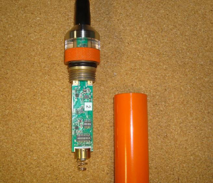
To gain access to the electronic PCB board for unit configuration remove the antenna cap on the
pressure case by rotating the cap counterclockwise by hand.
PLEASE NOTE: When removing or installing lens cap apply hand pressure to the knurled portion of the
cap only. Hand-tighten the lens cap only when reinstalling.
Removal of the PCB from the case will cycle power. Following a power cycle on the board the unit will
default to the ON state.
PLEASE NOTE: Following any disconnection of PCB from batteries, wait for a period of two minutes
before reconnecting. This period of time is required to let the circuit fully discharge and ensures that the
device will function optimally.
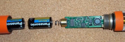
Figure 2: PCB Removed From Pressure Case
6.1 On/Off
Power to the Mini-Beacon 1000 PCB can be controlled by placing switch #1 on the 8 position DIP switch
in the on or off positions. See Table 2: 8 Position DIP Switch and Figure 3: PCB Showing DIP Switch
Locations.
To enable magnetic reed switch functionality switch #1 on the 4 position DIP switch must be in the on
position. See Table 1: 4 Position DIP Switch and Figure 3: PCB Showing DIP Switch Locations.

Mini-Beacon 1000
Operation & Maintenance Manual
January 2012
TD 12-024 Version 1.1
© METOCEAN DATA SYSTEMS | All Rights Reserved
Page 8
6.2 Daylight Off
The Mini-Beacon 1000 is equipped with a light sensor to allow for the daylight off functionality. To enable
this option, switch #2 on the 4 position DIP switch must be in the on position. See Table 1: 4 Position
DIP Switch and Figure 3: PCB Showing DIP Switch Locations.
Table 1: 4 Position DIP Switch
4 POSITION DIP SWITCH
SWITCH #
CONTROLS
POSITION
FUNCTION
1
REED SWITCH
ON
ENABLE
OFF
DISABLE
2
LIGHT SENSOR
ON
ENABLE
OFF
DISABLE
3
RESERVED –
PLEASE KEEP IN OFF
POSITION
OFF
N/A
4
RESERVED –
PLEASE KEEP IN OFF
POSITION
OFF
N/A
6.3 RF Frequency
The Mini-Beacon 1000 can be configured to transmit on any of the preset frequencies. RF transmission
frequency configuration is accomplished using switches #2 and #3 on the 8 position DIP switch. See
Table 2: 8 Position DIP Switch, Table 3: RF Frequency and Figure 3: PCB Showing DIP Switch
Locations.

Mini-Beacon 1000
Operation & Maintenance Manual
January 2012
TD 12-024 Version 1.1
© METOCEAN DATA SYSTEMS | All Rights Reserved
Page 9
6.4 RF Pulse Duration
Transmission pulse duration can be configured for 1, 2, 3, and 4 seconds. Pulse duration configuration is
accomplished using switches #4, and #5 on the 8 position DIP switch. See Table 2: 8 Position DIP
Switch, Table 4: RF Pulse Duration and Figure 3: PCB Showing DIP Switch Locations.
Table 2: 8 Position DIP Switch
8 POSITION DIP SWITCH
SWITCH #
CONTROLS
POSITION
FUNCTION
1
POWER TO PCB
ON
ON
OFF
OFF
2
RF FREQUENCY
*SEE TABLE RF FREQUENCY
3
4
RF
PULSE DURATION
* SEE TABLE RF PULSE DURATION
5
6
DUTY CYCLE
* SEE TABLE DUTY CYCLE
7
8
RESERVED –
PLEASE KEEP IN
OFF POSITION
OFF
N/A
Mini-Beacon 1000
Operation & Maintenance Manual
January 2012
TD 12-024 Version 1.1
© METOCEAN DATA SYSTEMS | All Rights Reserved
Page 10
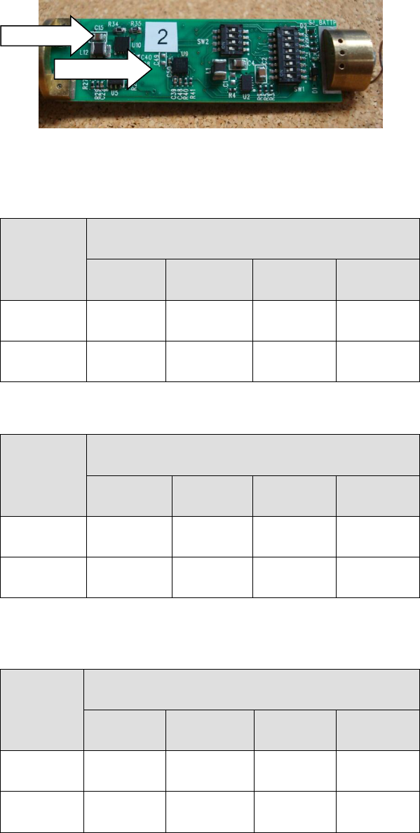
Figure 3: PCB Showing DIP Switch Locations
Table 3: RF Frequency
SWITCH #
RF FREQUENCY
A
B
C
D
2
OFF
ON
OFF
ON
3
OFF
OFF
ON
ON
Table 4: RF Frequency (1000A)
SWITCH #
RF FREQUENCY
A
B
C
D
2
OFF
ON
N/A
N/A
3
OFF
OFF
N/A
N/A
Table 5: RF Pulse Duration
SWITCH #
RF PULSE DURATION (SECONDS)
1
2
3
4
4
OFF
ON
OFF
ON
5
OFF
OFF
ON
ON
8 Position DIP
4 Position
DIP

Mini-Beacon 1000
Operation & Maintenance Manual
January 2012
TD 12-024 Version 1.1
© METOCEAN DATA SYSTEMS | All Rights Reserved
Page 11
Table 6: Duty Cycle
SWITCH #
DUTY CYCLE
RESERVED:
DO NOT USE
RESERVED:
DO NOT USE
17%
10%
6
OFF
ON
OFF
ON
7
OFF
OFF
ON
ON
6.5 Duty Cycle
Duty cycle is the percentage of transmission time in a complete transmission cycle (i.e. transmission and
non-transmission combined).
Duty Cycle (%) = (transmission time/complete cycle time)x100
The Mini-Beacon 1000 can be configured for 10% or 17% duty cycle. Duty cycle configuration is
accomplished using switches #6, #7 on the 8 position DIP switch. Table 2: 8 Position DIP Switch,
Table 5: Duty Cycle and Figure 3: PCB Showing DIP Switch Locations.
Increasing duty cycle for a given pulse duration will decrease battery life.
Mini-Beacon 1000
Operation & Maintenance Manual
January 2012
TD 12-024 Version 1.1
© METOCEAN DATA SYSTEMS | All Rights Reserved
Page 12
7 Maintenance
There are no user repairable parts in the Mini-Beacon 1000. Return the unit to the factory for repairs.
7.1 Regular Maintenance
Rinse thoroughly with fresh water after every use
Protect lens from damage, scratching or impact
Always remove batteries when not in use
Always use fresh batteries
Protect “O” ring surface from damage
Replace worn or damaged “O” rings
Keep batteries and electronics dry
7.2 Battery Change
The Mini-Beacon 1000 uses 7 x CR123A Lithium cells. Install fresh batteries with the positive terminal
towards the PCB. See Figure 4: PCB Removed for Battery Change. Please ensure that the insulating
plastic tube remains within the pressure case during battery change.
PLEASE NOTE: Following any disconnection of PCB from batteries, wait for a period of two minutes
before reconnecting. This period of time is required to let the circuit fully discharge and ensures that the
device will function optimally.
PLEASE NOTE: Cycling power to the PCB will result in the device defaulting to the ON state.
Figure 4: PCB removed for battery change
Mini-Beacon 1000
Operation & Maintenance Manual
January 2012
TD 12-024 Version 1.1
© METOCEAN DATA SYSTEMS | All Rights Reserved
Page 13
7.3 “O” Ring Facts
A conservative estimate is that “O” rings will last for two to five years.
The main problem with “O” rings is that over time they can take a “set”. They lose their original round
shape and they become slightly flattened resulting in less compressibility. Reduced compressibility can
lead to a water leak near the surface. The best way to prevent a problem is to service the “O” rings
before every deployment.
Some of the main factors that can cause a “set” are:
High storage temperature (exceeding 40ºC) over time will cause the rubber to harden.
Exposure to sunlight and ozone will cause the “O” ring to deteriorate and stiffen.
Temperature does not have to be that cold for an “O” ring to lose a great deal of its flexibility. At 4ºC,
an “O” ring has stiffened significantly.
“O” rings must be lightly lubricated with silicone-based grease. We recommend “Parker Super O
Lube”.
A typical seal failure results in a very small amount of water, not a flooded case. Most seal failures
occur near the surface.
The “O” ring becomes less flexible as the rubber ages.
If you are operating or storing at low temperature, it makes it even more important to service the “O”
ring regularly.
7.4 “O” Ring Maintenance
MetOcean strongly recommends that “O” rings be serviced on a regular basis to ensure a reliable seal.
Remove and lubricate at least once a year, preferably more often, and replace every two years or
sooner. With regular maintenance, “O” rings will be very reliable and trouble free. It has been, however,
our observation that most “O” rings are neglected for years and expected to perform at the extremes of
their design limits.
There is one “O” ring that requires service on this device. The “O” ring is located on the lens cap.
Replace the “O” ring with 2 – 116 – N70, available from MetOcean or your local “O” ring supplier.
Lubricate lightly with a silicone grease, we recommend Parker Super O Lube.
7.5 Corrosion Prevention
Corrosion is a problem common to all metals used in the ocean. To help minimize corrosion the Mini-
Beacon 1000 is protected with a chromate conversion followed by powder coating process.
Do not mount the beacon directly against metal. Isolate the pressure case by wrapping it with vinyl tape
or similar at the contact points.

Mini-Beacon 1000
Operation & Maintenance Manual
January 2012
TD 12-024 Version 1.1
© METOCEAN DATA SYSTEMS | All Rights Reserved
Page 14
8 Specifications
Transmitter Output
50 mW max, pulse FSK
Transmitter Duty Cycle
17%, 1 sec. on, 5 sec. off
Harmonics
-40 dB minimum
Battery Life @ 4ºC
Approximately 25 days
Batteries
7 x CR123A Lithium
Operating & Storage Temperature
-40°C to +60°C (-40°F to +140°F)1
Ocean Depth Rating
1,000 meters (3,280 feet) – maximum
Frequency Range (1000)
Channel A: 154.585 MHz
Channel B: 159.480 MHz
Channel C: 160.725 MHz
Channel D: 160.785 MHz
Frequency Range (1000A)
Channel A: 159.150 MHz
Channel B: 159.200 MHz
FCC Identification
Pending
Canadian Identification
Pending
Range
2-4 nautical miles
Antenna
Field replaceable ¼ wave low profile
Weight with Batteries
In air 1.00 lb (0.45 kg)
In water 0.63 lb (0.29 kg)
Dimensions (exclusive of antenna)
14.60” long (370 mm), 1.13” diameter
(28.7 mm)
1Operating temperature range dependant on battery temperature specifications
Mini-Beacon 1000
Operation & Maintenance Manual
January 2012
TD 12-024 Version 1.1
© METOCEAN DATA SYSTEMS | All Rights Reserved
Page 15
9 Warranty
MetOcean Data Systems guarantees this product to be free from defective materials and workmanship
and agrees to remedy any such defects for a period of one year commencing from the date of purchase.
This warranty does not apply if the equipment has been subject to misuse, neglect, accident or improper
installation, or altered outside our factory, or to damage caused by defective batteries. MetOcean Data
Systems neither assumes nor authorizes any person to assume for it any other obligation or liability in
connection with this product, including damage resulting from design or equipment failure.