Mettler Toledo Heavy PO TE0002 WIRELESS FORKLIFT SCALE User Manual USERS MANUAL
Mettler-Toledo, Inc. Heavy Industrial PO WIRELESS FORKLIFT SCALE USERS MANUAL
USERS MANUAL

A17082300A
(3/05).00
Preliminary
MCFA
Forklift Scale
Service Manual

© Mettler-Toledo, Inc. 2004, 2005
No part of this manual may be reproduced or transmitted in any form or by any means, electronic or
mechanical, including photocopying and recording, for any purpose without the express written permission
of Mettler-Toledo, Inc.
U.S. Government Restricted Rights: This documentation is furnished with Restricted Rights.

METTLER TOLEDO
Publication Revision History
An overview of this manual’s revision history is compiled below.
Publication Name: MCFA Forklift Scale Service Manual
Publication Part Number: 17082300A Publication Date: 2/04
Part Number Date Revisions
17082300A(.01) 10/04 Revised load cell calibration procedure on pages 4-15, 7-1, and 7-2. Changed
caution message on page 2-2. Added caution message on page 2-8.
17082300A(.02) 12/04 Changed title on front cover to MCFA Forklift Scale Service Manual. Changed name
of product on page 1-1 to MCFA forklift scale. Added instructions to raise the forks
off the ground to power-up sequence on page 3-1.
A17082300A 3/05 Added information about Triplex version of scale: tools list and installation (Chapter
2), maintenance (Chapter 5), load cell replacement (Chapter 6), and parts list
(Chapter 8). Replaced screen shots in Chapters 3, 4, 6, and 7. Revised parts lists
and added parts for USB port and side shifter options (Chapter 8). Added new
Chapter 9 describing installation of USB port and side shifter options.

INTRODUCTION
This publication is provided solely as a guide for individuals who have received Technical Training in
servicing the METTLER TOLEDO product.
METTLER TOLEDO RESERVES THE RIGHT TO MAKE REFINEMENTS OR
CHANGES WITHOUT NOTICE.
Precautions
WARNING
PERMIT ONLY QUALIFIED PERSONNEL TO SERVICE THIS
EQUIPMENT. EXERCISE CARE WHEN MAKING CHECKS,
TESTS, AND ADJUSTMENTS THAT MUST BE MADE WITH
POWER ON. FAILING TO OBSERVE THESE PRECAUTIONS CAN
RESULT IN BODILY HARM.
READ this manual BEFORE
operating or servicing this
equipment.
FOLLOW these instructions
carefully.
SAVE this manual for future
reference.
DO NOT allow untrained
personnel to operate, clean,
inspect, maintain, service, or
tamper with this equipment.
ALWAYS DISCONNECT this
equipment from the power
source before cleaning or
performing maintenance.
CALL METTLER TOLEDO for parts,
information, and service.
WARNING
FOR CONTINUED PROTECTION AGAINST SHOCK HAZARD,
CONNECT TO PROPERLY GROUNDED OUTLET ONLY. DO NOT
REMOVE THE GROUND PRONG.
WARNING
DISCONNECT ALL POWER TO THIS UNIT BEFORE INSTALLING,
SERVICING, CLEANING, OR REMOVING THE FUSE. FAILURE TO
DO SO COULD RESULT IN BODILY HARM AND/OR PROPERTY
DAMAGE.
WARNING
BEFORE CONNECTING/DISCONNECTING ANY INTERNAL ELECTRONIC COMPONENTS OR
INTERCONNECTING WIRING BETWEEN ELECTRONIC EQUIPMENT, ALWAYS REMOVE
POWER AND WAIT AT LEAST 30 SECONDS. FAILURE TO OBSERVE THESE PRECAUTIONS
COULD RESULT IN BODILY HARM OR DAMAGE TO OR DESTRUCTION OF THE EQUIPMENT.
CAUTION
OBSERVE PRECAUTIONS FOR HANDLING ELECTROSTATIC
SENSITIVE DEVICES.
DANGER
BE SURE TO BLOCK THE LIFT BRACKET WHEN IT IS IN THE
RAISED POSITION. FAILURE TO OBSERVE APPROPRIATE SAFETY
PRECATIONS COULD RESULT IN BODILY HARM OR PROPERTY
DAMAGE.
DANGER
DO NOT REMOVE THE BOLTS FROM MORE THAN ONE FLEXURE
AT A TIME WHILE THE CARRIAGE IS INSTALLED ON THE
FORKLIFT. UNBOLTING MORE THAN ONE FLEXURE COULD
RESULT IN BODILY HARM OR PROPERTY DAMAGE.
DANGER
IF USED IN A HAZARDOUS AREA, THE HAZARDOUS AREA MUST
BE MADE SAFE PRIOR TO INSTALLATION, REPLACEMENT, OR
TROUBLESHOOTING. FAILURE TO COMPLY COULD RESULT IN
PERSONAL INJURY, DEATH, AND/OR PROPERTY DAMAGE.
CAUTION
CHANGES OR MODIFICATIONS NOT EXPRESSLY APPROVED BY METTLER TOLEDO COULD
VOID THE AUTHORITY TO OPERATE THIS EQUIPMENT.
CAUTION
THERE IS A RISK OF EXPLOSION IF A BATTERY IS REPLACED WITH AN INCORRECT TYPE OF
BATTERY. DISPOSE OF BATTERIES ACCORDING TO LOCAL REGULATIONS. FOR DISPOSAL
INFORMATION, REFER TO THE PRODUCT INFORMATION SHEET FOR NICKEL METAL
HYDRIDE BATTERIES (NiMH) AT www.panasonic.com OR REFER TO THE RECHARGEABLE
BATTERY RECYCLING CORPORATION (www.rbrc.org).
Contents
1 Introduction.................................................................................................... 1-1
FCC Notice..........................................................................................................................1-2
2 Installation..................................................................................................... 2-1
General ..............................................................................................................................2-1
Tools.................................................................................................................................... 2-1
Install Scale Controller........................................................................................................2-2
Remove the Forklift Truck’s Lift Bracket.................................................................................2-2
Install the Simplex Scale Carriage.......................................................................................2-6
Install the Triplex Scale Carriage.........................................................................................2-9
Batteries...........................................................................................................................2-12
Geo Index.........................................................................................................................2-13
Shift Adjustment................................................................................................................2-13
3 Scale Operations ............................................................................................ 3-1
Power-up Sequence.............................................................................................................3-1
Weighing Screen.................................................................................................................3-1
Push Buttons......................................................................................................................... 3-2
Weighing Operations...........................................................................................................3-3
Gross Weighing .................................................................................................................... 3-3
Net Weighing with Push Button Tare....................................................................................... 3-4
Net Weighing with Keyboard Tare........................................................................................... 3-4
Accumulating Gross Weights.................................................................................................. 3-5
Accumulating Net Weights..................................................................................................... 3-5
SmartWeigh Transactions...................................................................................................... 3-6
4 Scale Setup.................................................................................................... 4-1
Setup Screens.....................................................................................................................4-1
Scale..................................................................................................................................4-1
Filter.................................................................................................................................... 4-1
Tare ..................................................................................................................................... 4-4
Zero..................................................................................................................................... 4-5
Stability................................................................................................................................4-7
Battery Levels....................................................................................................................... 4-9
Calibration ......................................................................................................................... 4-13
Factory Use......................................................................................................................... 4-19
Reset.................................................................................................................................. 4-20
Application .......................................................................................................................4-21
Accumulate......................................................................................................................... 4-21
SmartWeigh........................................................................................................................ 4-21
Memory.............................................................................................................................. 4-23
Reset.................................................................................................................................. 4-25
Terminal...........................................................................................................................4-25
Date/Time........................................................................................................................... 4-25
Passwords.......................................................................................................................... 4-26
Calibrate Touch................................................................................................................... 4-27
Operating System................................................................................................................ 4-27
Brand Setup........................................................................................................................ 4-29
Reset.................................................................................................................................. 4-30
Communications...............................................................................................................4-30
Scale Radio........................................................................................................................ 4-30
COM1................................................................................................................................. 4-35
Reset.................................................................................................................................. 4-37
Maintenance.....................................................................................................................4-37
Log..................................................................................................................................... 4-37
Diagnostics......................................................................................................................... 4-38
Reset.................................................................................................................................. 4-43
Exit Setup.........................................................................................................................4-43
5 Routine Care and Maintenance........................................................................ 5-1
General ..............................................................................................................................5-1
Cleaning.............................................................................................................................5-2
6 Troubleshooting.............................................................................................. 6-1
General ..............................................................................................................................6-1
Error Messages...................................................................................................................6-2
Scale Controller..................................................................................................................6-4
Check Mechanical Components............................................................................................6-4
Check Overload Gaps ..........................................................................................................6-5
Check Wiring......................................................................................................................6-6
Check Force Data................................................................................................................6-6
Check Load Cells ................................................................................................................6-7
Load Cell Replacement........................................................................................................6-8
Removing a Chain Load Cell (Simplex).................................................................................. 6-8
Installing a New Chain Load Cell (Simplex) ......................................................................... 6-11
Removing a Drag Load Cell (Simplex).................................................................................. 6-12
Installing a New Drag Load Cell (Simplex)........................................................................... 6-13
Removing a Chain Load Cell (Triplex).................................................................................. 6-15
Installing a New Chain Load Cell (Triplex) ........................................................................... 6-18
Removing a Drag Load Cell (Triplex).................................................................................... 6-19
Installing a New Drag Load Cell (Triplex)............................................................................. 6-20
Adjust Load Cell Force.......................................................................................................6-22
7 Calibration..................................................................................................... 7-1
General ..............................................................................................................................7-1
Calibrate Load Cells............................................................................................................7-1
Span Adjustment.................................................................................................................7-3
Calibrate Linearity...............................................................................................................7-5
Calibrate Angles .................................................................................................................7-8
Establish Zero...................................................................................................................7-13
8 Service Parts.................................................................................................. 8-1
Scale Controller..................................................................................................................8-1
Scale Carriage....................................................................................................................8-2
Telemetry Enclosure............................................................................................................8-6
Side Shifter Kit....................................................................................................................8-8
9 Forklift Scale Options...................................................................................... 9-1
USB Port.............................................................................................................................9-1
Side Shifter Kit....................................................................................................................9-2
10 Appendix ..................................................................................................... 10-1
Geo Index.........................................................................................................................10-1
Chapter 1: Introduction
FCC Notice
1
Introduction
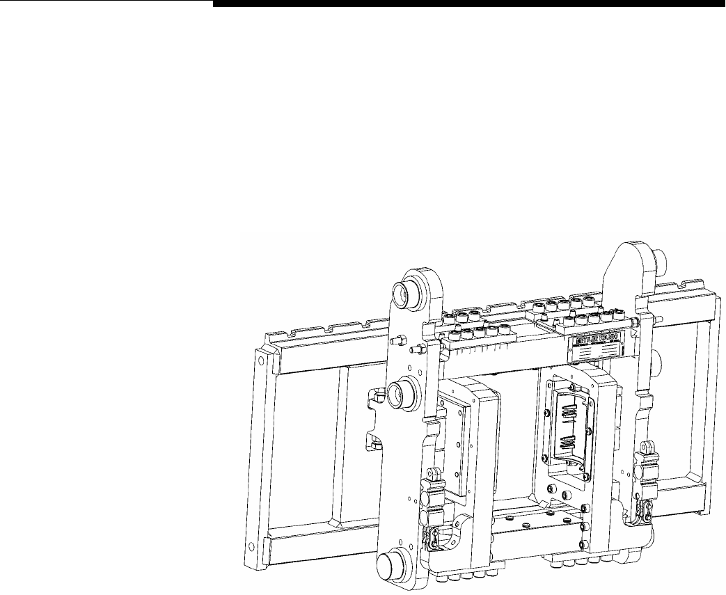
The MCFA forklift scale is a fully electronic scale with a capacity of 5,000 lb (2,000
kg). The scale consists of two components: (1) a scale carriage, which is installed in
place of the forklift truck’s lift bracket, and (2) a scale controller, which is mounted on
the forklift truck’s head guard. The scale carriage and controller communicate by radio,
so there are no wiring connections between them to limit the movement of the forks.
Figure 1-1: Forklift Scale Carriage (Simplex Version)
This manual explains how to install, operate, and service the MCFA forklift scale. If any
information in the manual is incorrect or missing, please use the Publication Suggestion
Report at the back of the manual to tell us about it.
(3/05) 1-1
METTLER TOLEDO MCFA Forklift Scale Service Manual
FCC Notice
MCPC Scale Controller (FCC ID: RITSC0001)
This device complies with Part 15 of the FCC Rules. Operation is subject to the following
two conditions: (1) this device may not cause harmful interference, and (2) this device
must accept any interference received, including interference that may cause undesired
operation.
MCSB Simplex Scale Carriage (FCC ID: RITTE0001)
This device complies with Part 15 of the FCC Rules. Operation is subject to the following
two conditions: (1) this device may not cause harmful interference, and (2) this device
must accept any interference received, including interference that may cause undesired
operation.
MCTB Triplex Scale Carriage (FCC ID: RITTE0002)
This device complies with Part 15 of the FCC Rules. Operation is subject to the following
two conditions: (1) this device may not cause harmful interference, and (2) this device
must accept any interference received, including interference that may cause undesired
operation.
CAUTION
CHANGES OR MODIFICATIONS NOT EXPRESSLY APPROVED BY METTLER TOLEDO COULD
VOID THE AUTHORITY TO OPERATE THIS EQUIPMENT.
(3/05)
1-2

Chapter 2: Installation
General
2
Installation
General
When you receive your forklift scale, check all items against the shipping bill of lading.
If any items are missing, notify the carrier immediately. Inspect the packing container
and scale for freight damage. If you find damage, contact your freight carrier
immediately in order to collect damages.
Tools The following tools are needed to install and calibrate a forklift scale:
Simplex Version
Crane or lifting device (capacity 2,500 lb)
Torque wrench with 3/8-inch hex bit attachment (flexure bolts)
12-mm wrench (main roller bolts)
14-mm wrench (side roller assembly bolts)
24-mm wrench (chain anchor nuts)
3/4-inch wrench (bumper bolts and drag load cell mounting nuts)
10-mm wrench (bolts for mounting controller)
Triplex Version
Crane or lifting device (capacity 2,500 lb)
Torque wrench with 5/16-, 3/8-, and 1/2-inch hex bit attachments
12-mm wrench (main roller bolts)
16-mm wrench (side roller assembly bolts)
24-mm wrench (chain anchor nuts)
3/4-inch wrench (bumper bolts and drag load cell mounting nuts)
10-mm wrench (bolts for mounting controller)
1.25-inch open-end wrench
(3/05) 2-1
METTLER TOLEDO MCFA Forklift Scale Service Manual
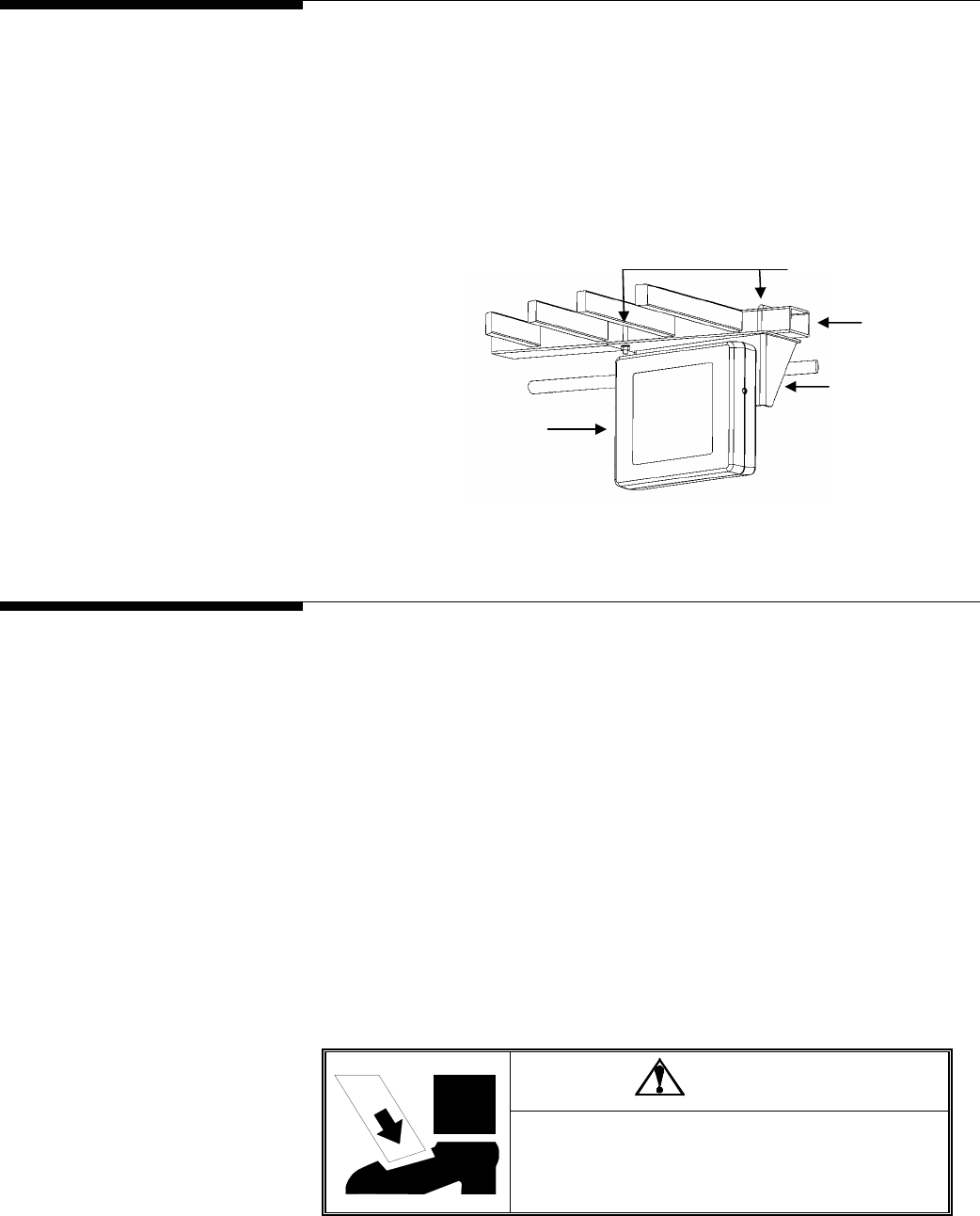
Install Scale Controller 1.
Use a pair of U-bolts to attach the mounting bracket to the forklift truck’s head
guard. Position it so that the driver will be able to view the controller easily.
2.
Bolt the controller to the mounting bracket, using four hexagonal head screws and
washers (see Figure 2-1).
3.
Connect the controller to the forklift truck’s time-delay relay harness. The harness
should be installed according to the manufacturer’s instructions.
U-Bolts
Head Guard
Mounting Bracket
Scale Controller
Figure 2-1: Scale Controller and Mounting Bracket
Remove the Forklift
Truck’s Lift Bracket 1.
Park the forklift truck on a level surface, and make sure the mast is in the vertical
position.
2.
Remove both of the forks.
3.
If the forklift truck is equipped with a load backrest extension, remove the load
backrest extension.
4.
Raise the mast so that the lift bracket is at a comfortable working height (3 or 4 feet
off the ground).
5.
Wrap a sling securely around the lift bracket’s upper fork bar.
6.
Attach the sling to a crane (or other lifting device with a capacity of at least 500
lb), and use the crane to raise the lift bracket so that the chains have some slack in
them.
DANGER
BE SURE TO BLOCK THE LIFT BRACKET WHEN IT IS IN THE
RAISED POSITION. FAILURE TO OBSERVE APPROPRIATE
SAFETY PRECATIONS COULD RESULT IN BODILY HARM OR
PROPERTY DAMAGE.
(3/05)
2-2
Chapter 2: Installation
Remove the Forklift Truck’s Lift Bracket
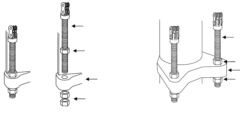
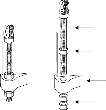
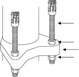
7.
Disconnect the two chain anchors from the mast by removing the lower jam nut
from each anchor (see Figure 2-2). Keep the nuts with the chain anchor to use
them for installing the scale carriage.
Chain Anchor
Chain Anchor
Jam Nuts
Mast
Jam Nut
Simplex Version
Jam Nut
Mast
Jam Nuts
Triplex Version
Figure 2-2: Chain Anchor Assembly
8.
Remove the chains from the pulleys at the top of the mast. Then position the chains
over the front of the lift bracket so that they will not interfere with removing the lift
bracket from the mast.
9.
Raise the bottom of the inner mast at least 2 feet off the floor to allow enough room
to remove the lift bracket from the bottom of the mast.
10.
Use the crane to lower the lift bracket to the floor and remove it from the bottom of
the mast.
11.
Place the lift bracket on a stable working surface, with the front side of the lift
bracket facing downward to provide easy access to the rollers and chain mounts.
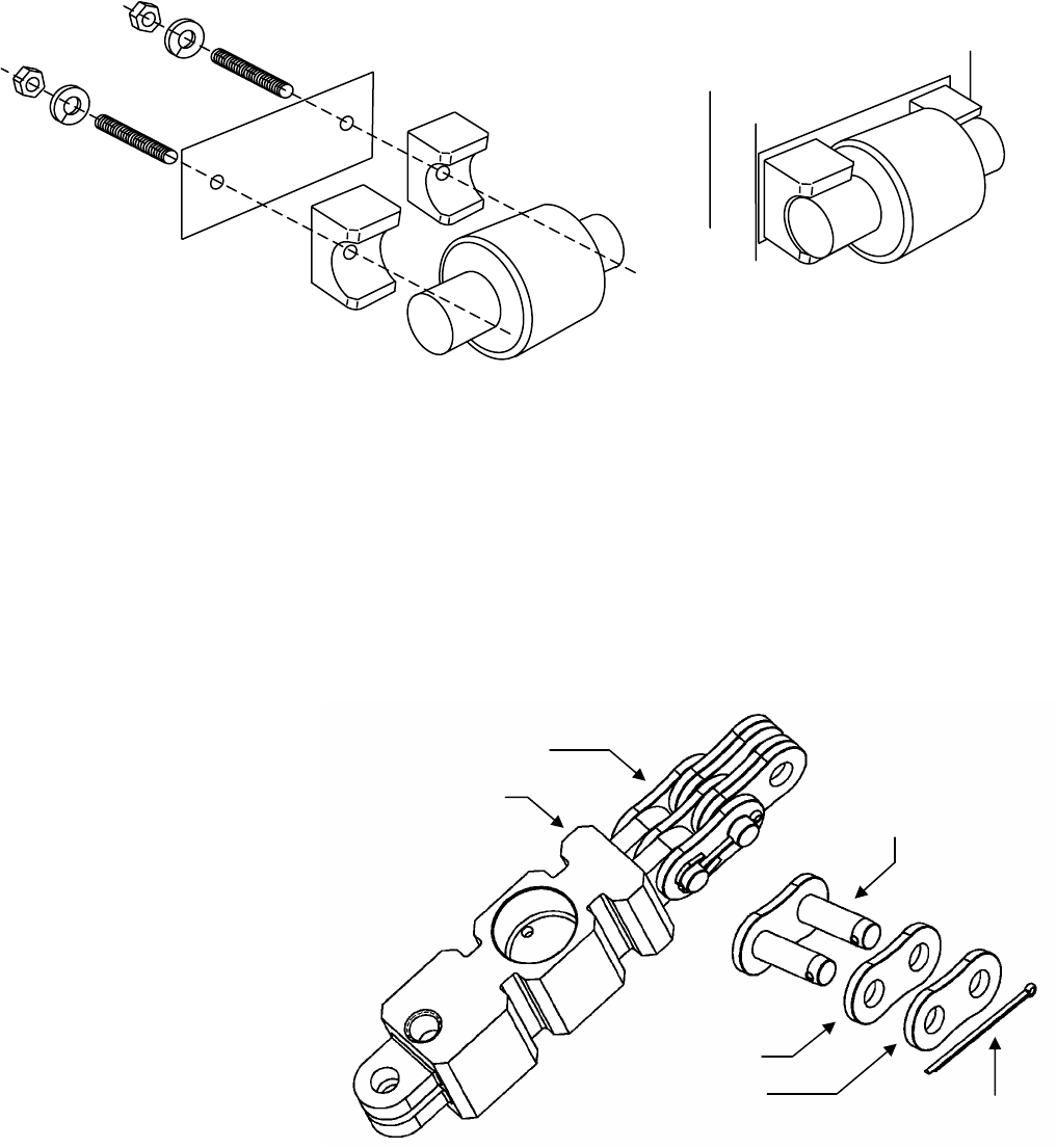
12.
Disconnect the two chains from the lift bracket. Remove the cotter pin from the
master link that is connected to the 90° joint in each chain (see Figure 2-3). Then
take apart the master link, using a C-clamp or similar device to press the master
link through the link plates. Do not use a hammer or other tool to strike the master
link. It could damage the link. Keep the chains and master links to install on the
scale carriage.
(3/05) 2-3
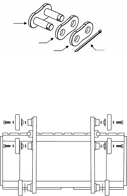
METTLER TOLEDO MCFA Forklift Scale Service Manual
Master Link
Link Plate (Large Holes)
Cotter Pin
Link Plate (Small Holes)
Figure 2-3: Master Link Assembly
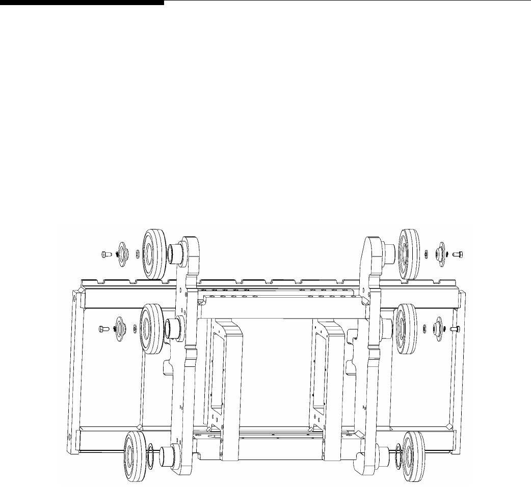
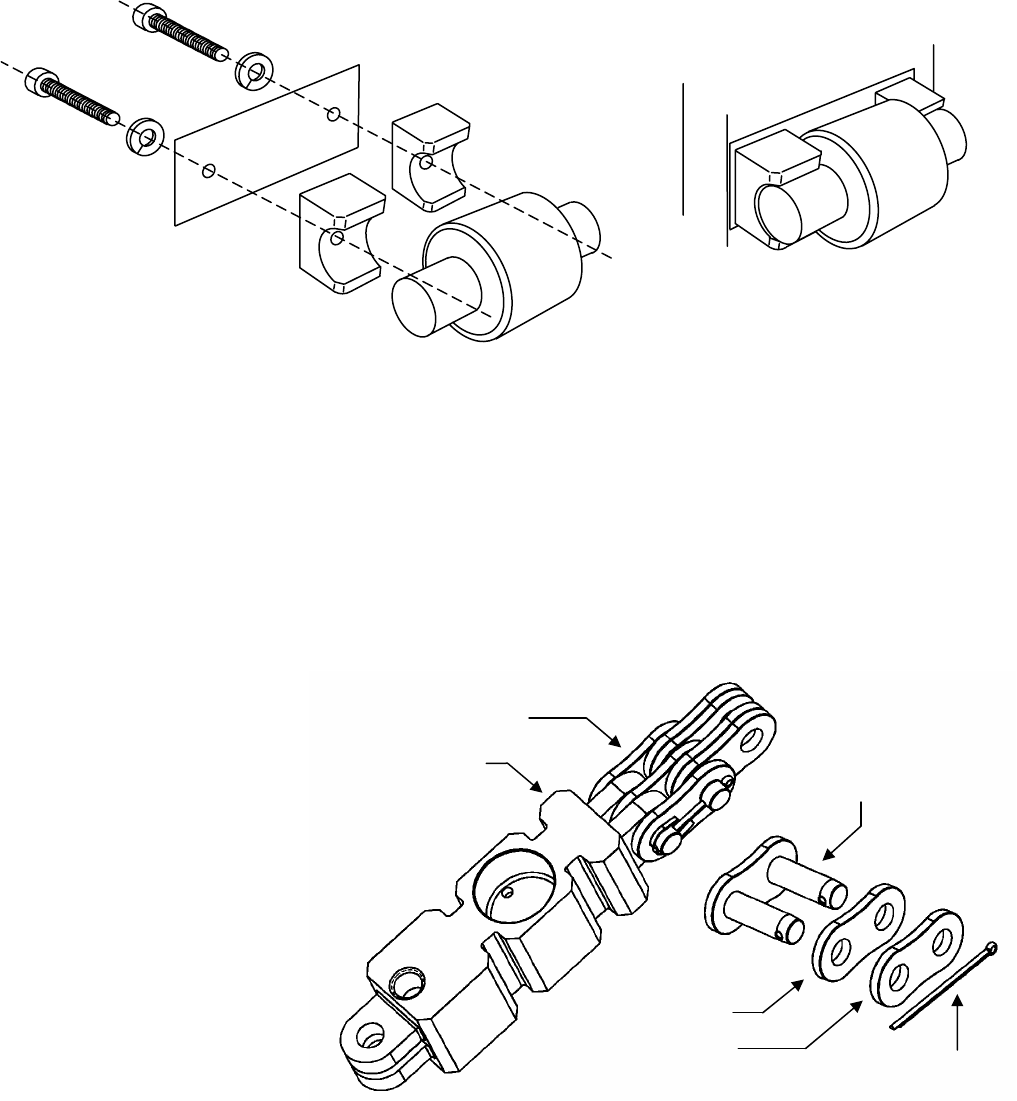
13.
Remove the six main rollers from the lift bracket (see Figure 2-4). The two top
rollers on each side of the lift bracket are secured with screws. The bottom roller on
each side of the lift bracket can be removed by hand. Save the rollers, screws,
washers, and shims so that you can install them on the scale carriage.
Figure 2-4: Remove Main Rollers
14.
Locate the side roller on each side of the lift bracket. Remove the two bolts that
secure each side roller assembly to the lift bracket (see Figure 2-5). Keep these
assemblies together because you will need to install them on the scale carriage.
Note the position of any shims used in the assemblies.
(3/05)
2-4
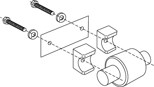
Chapter 2: Installation
Remove the Forklift Truck’s Lift Bracket
Figure 2-5: Side Roller Assembly
15.
Set the lift bracket aside, and remove the sling from it.
(3/05) 2-5
METTLER TOLEDO MCFA Forklift Scale Service Manual
Install the Simplex
Scale Carriage 1.
Park the forklift truck on a level surface, and make sure the mast is in the vertical
position.
2.
Place the scale carriage on a stable working surface, with the front side of the
carriage facing downward to provide easy access to the rollers and chain load
cells.
3.
Install the two lower main rollers by sliding them onto the roller shafts at the bottom
of each side of the scale carriage (see Figure 2-6). Be sure to install any shims that
were removed from the forklift truck’s lift bracket.
4.
Install the other four main rollers on the scale carriage, securing them with the bolts
that were removed from the lift bracket (see Figure 2-6).
Figure 2-6: Install Main Rollers
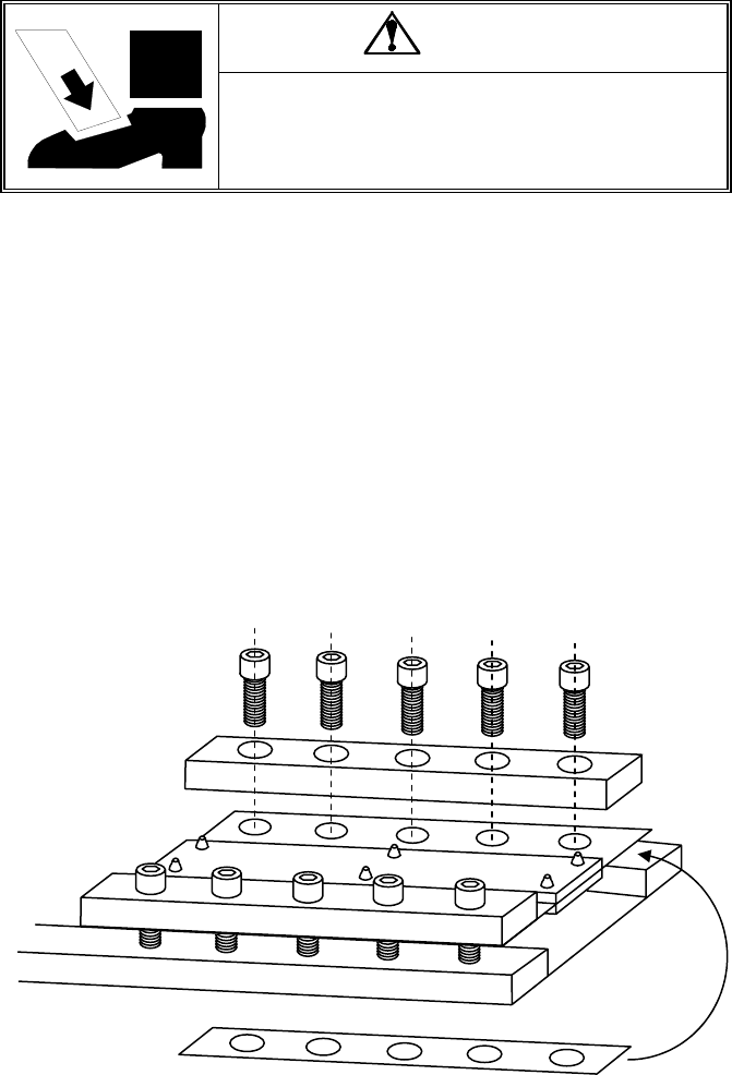
5.
Mount the two side roller assemblies (including shims) on the scale carriage (see
Figure 2-7). Do not use the bolts that were removed from the lift bracket. Instead,
use the studs and nuts provided with the scale carriage. Align the two holes in each
side roller assembly with the holes located midway between the two bolted rollers
on each side of the carriage. Insert the studs in the holes and screw them into the
assembly. Then place the washers and nuts on the ends of the studs and tighten
them against the carriage.
(3/05)
2-6
Chapter 2: Installation
Install the Simplex Scale Carriage
Figure 2-7: Side Roller Assembly
6.
Use a master link to connect each chain to one of the chain load cells on the scale
carriage. Assemble the master link as shown in Figure 2-8. Using a C-clamp or
similar device, press the master link assembly together just enough so that you can
insert the cotter pin in the holes. If the link is too tight, it can bind against the load
cell and chain mount. If the link does not rotate freely on the load cell or chain,
press the master link back through the link plates until it rotates freely.
NOTE: When a forklift scale is installed, a standard chain should have 34 links
(including master links). Add or remove links if necessary.
Figure 2-8: Connect Chain to Load Cell with Master Link
Assembled Master Link
Chain Load Cell Master Link
Link Plate
(Large Holes)
Link Plate
(Small Holes) Cotter Pin
7.
Position the chains over the front of the carriage so that they will not interfere when
you install the carriage in the forklift mast.
8.
Raise the bottom of the inner mast at least 2 feet off the floor to allow enough room
to install the carriage from the bottom of the mast.
9.
Wrap a sling securely around the upper part of the scale carriage.
(3/05) 2-7
METTLER TOLEDO MCFA Forklift Scale Service Manual
10.
Attach the sling to a crane (or other lifting device with a capacity of
at least 500
ted
11.
to
12.
r
13.
the anchor into the hole in
Figure 2-9: Chain Anchor Assembly
5.
Remove the sling from the scale carriage.
ck on the lift truck, positioning a fork at
17.
the mast are completely
18.
hain anchors so that each chain has 3/4 inch of slack. This will allow
19.
rks
lb), and use the crane to lift the scale carriage. Position the carriage so that its
main rollers fit into the bottom of the mast channel. The chain load cells are loca
on the back side of the scale carriage.
Raise the carriage to a comfortable working position, keeping the main rollers
aligned inside the mast channel. Move the carriage up and down several times
make sure that it moves freely within the mast. If the carriage fits too tightly within
the mast, you might need to remove shims from the bottom rollers or side rollers.
Position two blocks of wood (3 inches high) on the floor under the carriage’s lowe
fork bar. Lower the inner mast and carriage until the fork bar rests on the blocks.
Route the chains over the pulleys at the top of the mast.
14.
Remove the lower nut from each chain anchor and insert
the mast, below and behind the chain pulleys. Place the lower nut on the threaded
anchor and tighten it until both it and the upper nut are tight against the mast (see
Figure 2-9). You will need to adjust the anchors later, so do not tighten the nuts too
much. Make sure there is no slack in the chains, so that the carriage does not drop
when you remove the sling.
Chain Anchor
Jam Nuts
Mast
Jam Nut
1
16.
Raise the carriage slightly. Put the forks ba
the next to last notch on each side of the carriage.
Lower the carriage to the floor so that the stages of
collapsed.
Adjust the c
room for the chains to adjust when the mast is set at an angle. With the mast in the
vertical position and the carriage fully lowered, the distance between the floor and
the bottom of the scale carriage should be 76 to 80 mm (about 3 inches).
After installing the scale controller and scale carriage, place a pallet on the fo
and exercise the scale to make sure that all components seat properly. Repeatedly
place a test weight on the scale, positioning it on the center of the scale and at
each corner of the scale.
(3/05)
2-8
Chapter 2: Installation
Install the Triplex Scale Carriage
Install the Triplex Scale
Carriage 1.
Park the forklift truck on a level surface, and make sure the mast is in the vertical
position.
2.
Place the scale carriage on a stable working surface, with the front side of the
carriage facing downward to provide easy access to the rollers and chain load
3.
two lower main rollers by sliding them onto the roller shafts at the bottom
s
4.
the other four main rollers on the scale carriage, securing them with the bolts
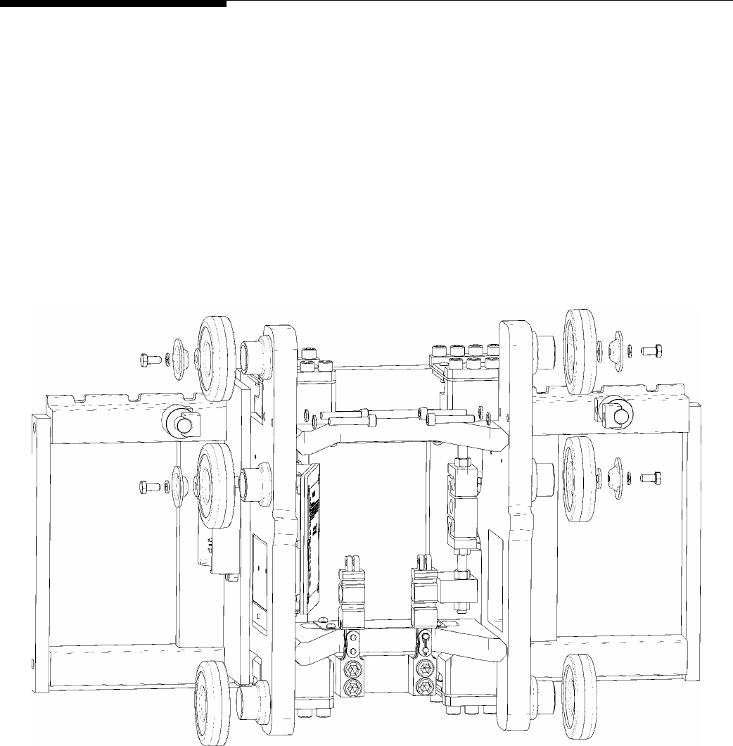
5.
Mount the two side roller assemblies (including shims) on the scale carriage (see
Figures 2-10 and 2-11). Align the two holes in each side roller assembly with the
h o bolted rollers on each side of the carriage.
Use two socket head screws and washers to secure each side roller assembly.
cells.
Install the
of each side of the scale carriage (see Figure 2-10). Be sure to install any shim
that were removed from the forklift truck’s lift bracket.
Install
that were removed from the lift bracket (see Figure 2-10).
Figure 2-10: Install Main Rollers
oles located midway between the tw
(3/05) 2-9
METTLER TOLEDO MCFA Forklift Scale Service Manual
6.
Use a master link to connect each chain to one of the chain load cells on the scale
shown in Figure 2-12. Using a C-clamp or
similar device, press the master link assembly together just enough so that you can
insert the cotter pin in the holes. If the link is too tight, it can bind against the load
Figure 2-11: Side Roller Assembly
carriage. Assemble the master link as
cell and chain mount. If the link does not rotate freely on the load cell or chain,
press the master link back through the link plates until it rotates freely.
NOTE: When a forklift scale is installed, a standard chain should have 33 links
(including master links). Add or remove links if necessary.
Chain Load Cell
As
Master Link
sembled Master Link
Link Plate
es) Cotter Pin
Link Plate
(Large Holes)
(Small Hol
Figure 2-12: Connect C d C nk
7.
Position the chains over the front of the carriage so that they will not interfere when
you insta
.
Raise the bottom of the inner mast at least 2 feet off the floor to allow enough room
9.
t of the scale carriage.
hain to Loa ell with Master Li
ll the carriage in the forklift mast.
8
to install the carriage from the bottom of the mast.
Wrap a sling securely around the upper par
(3/05)
2-10
Chapter 2: Installation
Install the Triplex Scale Carriage
ition the carriage so that its
cells are located
ims from the bottom rollers or side rollers.
13.
ht against the mast (see
o do not tighten the nuts
y
15.
Remove the sling from the scale carriage.
16.
Raise the carriage s , positioning a fork at
the next to last notch on each side of the carriage.
tages of the mast are completely
18.
4 inch of slack. This will allow
r and
f the scale carriage should be 76 to 80 mm (about 3 inches).
10.
Attach the sling to a crane (or other lifting device with a capacity of at least 500
lb), and use the crane to lift the scale carriage. Pos
main rollers fit into the bottom of the mast channel. The chain load
on the back side of the scale carriage.
11.
Raise the carriage to a comfortable working position, keeping the main rollers
aligned inside the mast channel. Move the carriage up and down several times to
make sure that it moves freely within the mast. If the carriage fits too tightly within
the mast, you might need to remove sh
12.
Position two blocks of wood (3 inches high) on the floor under the carriage’s lower
fork bar. Lower the inner mast and carriage until the fork bar rests on the blocks.
Route the chains over the pulleys at the top of the mast.
14.
Remove the lower nut from each chain anchor and insert the anchor into the hole in
the mast, below and behind the chain pulleys. Place the lower nut on the threaded
anchor and tighten it until both it and the upper nut are tig
Figure 2-13). You will need to adjust the anchors later, s
too much. Make sure there is no slack in the chains, so that the carriage does not
drop when you remove the sling.
Figure 2-13: Chain Anchor Assembl
Chain Anchor
Jam Nuts
Mast
Jam Nut
lightly. Put the forks back on the lift truck
17.
Lower the carriage to the floor so that the s
collapsed.
Adjust the chain anchors so that each chain has 3/
room for the chains to adjust when the mast is set at an angle. With the mast in the
vertical position and the carriage fully lowered, the distance between the floo
the bottom o
19.
After installing the scale controller and scale carriage, place a pallet on the forks
and exercise the scale to make sure that all components seat properly. Repeatedly
place a test weight on the scale, positioning it on the center of the scale and at
each corner of the scale.
(3/05) 2-11
METTLER TOLEDO MCFA Forklift Scale Service Manual
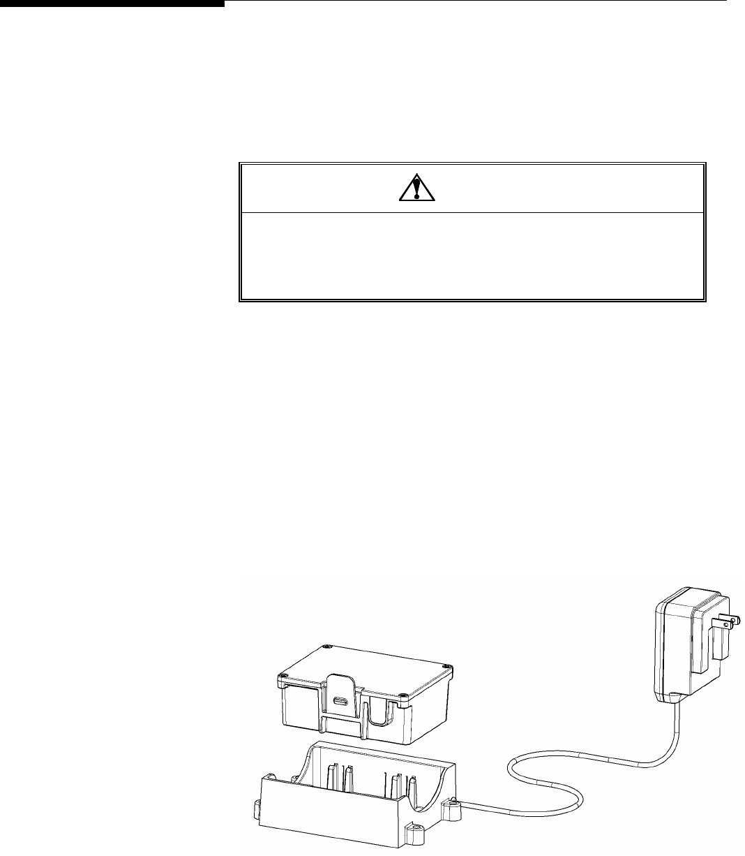
Batteries
A 12-volt battery pack is used to power the scale’s load cells and carriage radio. The
scale is supplied with two batteries and a battery charger. New batteries must be
charged before they can be used. A fully charged battery will allow you to operate the
scale for up to 36 hours. The battery level indicator on the scale controller’s main
weighing screen alerts the driver when the battery’s voltage level is low.
CAUTION
THERE IS A RISK OF EXPLOSION IF A BATTERY IS REPLACED WITH AN INCORRECT
TYPE OF BATTERY. DISPOSE OF BATTERIES ACCORDING TO LOCAL REGULATIONS.
FOR DISPOSAL INFORMATION, REF NFORMATION SHEET FOR
NICKEL METAL HYDRIDE BATTERIE sonic.com OR REFER TO
THE RECHARGEABLE BATTERY RECYCLING CORPORATION (www.rbrc.org).
ER TO THE PRODUCT I
S (NiMH) AT www.pana
• tion the
the
To remove a battery, press the plastic tab toward the center of the battery and pull
•
outlet (110 volts). It will take 12 to 16
recharge it. A red light on the battery
To install a battery, insert it in the scale carriage’s battery compartment. Posi
battery so that the metal contacts on its side fit against the metal contacts in
battery compartment.
•
the battery out of the battery compartment.
To charge a battery, insert it in the battery charger (see Figure 2-14). Then plug the
battery charger into a standard electrical
hours to provide the initial charge for a new battery. Once a battery has been used,
it should take no more than 3 to 4 hours to
charger indicates that the battery is being charged. A green light indicates that the
battery is fully charged. When a battery is fully charged, the charger goes into
trickle mode, so there is no danger of damaging a battery by overcharging it.
Figure 2-14: Battery and Batter Charger
(3/05)
2-12

Chapter 2: Installation
Geo Index
Geo Index
To compensate for local gravitational forces, change the geo index to the setting for the
location where the scale will be used. The factory default setting is 16 (the geo index for
Worthington, Ohio, USA). To determine the geo index for a location, refer to the
appendix (Chapter 10). You must know the geographical coordinate for the location
and the elevation above sea level.
1.
To change the geo index, enter the scale controller’s setup mode by touching the
Setup button on the main weighing screen.
2.
Touch the Scale button, touch the Calibration button, and then touch the Where
Used button.
3.
A keypad is used to enter the geo index. Type a number in the data field by
touching the numeric keys on the keypad (the range is 0 to 31). Touch the Clear
button if you wish to clear the data field and start over.
4.
Touch the Enter button to confirm your selection or the Cancel button to cancel any
changes that you made.
Shift Adjustment
Forklift scales are calibrated at the factory and should not need to be recalibrated when
they are installed. You should, however, check the scale after installing it to see if it
needs to be shift adjusted. A correctly adjusted scale will give you the same weight
reading no matter where on the forks you place a test weight. If the weight readings at
the shift test locations are out of tolerance, shift adjust the scale to correct the problem.
Park the forklift truck on a level surface, place a pallet on the forks, raise the forks 12 to
15 inches off the ground, set the mast to the vertical position, and shut off the forklift
truck’s motor. Then check the scale’s repeatability by placing a test weight on the same
location on the pallet several times to make sure that you get the same weight reading
each time.
After verifying the scale’s repeatability, check to see if the scale needs to be shift
adjusted. For shift adjustments, we recommend using test weights equal to one half the
scale’s maximum weighing capacity. The test weights must meet the specified National
Institute of Standards and Technology Handbook 44 accuracy requirements.
NOTE: When performing a shift adjustment, use the weight readings on the data screen
instead of those on the main weighing screen. The weight readings on the data screen
are displayed to two decimal places, although the number in the second decimal place
might not be stable.
(3/05) 2-13
METTLER TOLEDO MCFA Forklift Scale Service Manual
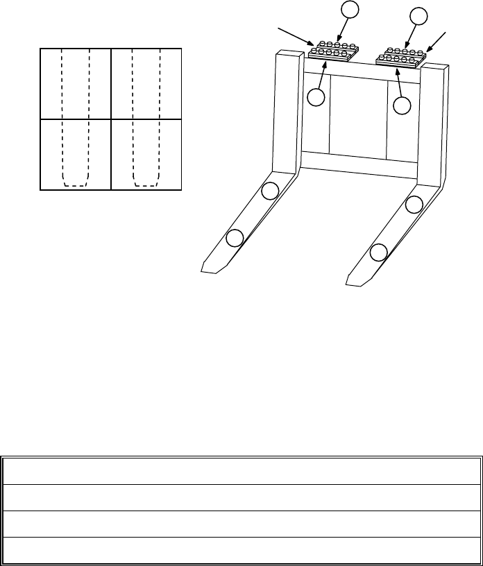
Shift Test Locations
Place a pallet or other flat surface (approximately 4 feet by 4 feet) on the forks and
make sure that it is level. Figure 2-15 shows test weight locations (1, 2, 3, and 4) at
ions.
t reading 1 is greater than 2 → Shim at location A
the center of each quadrant of the pallet. Place the test weight at location 1 and record
the weight reading. Then move the test weight to location 2 and record the weight
reading. Continue until you have taken a weight reading at each of the four locat
3
4
1
2
A
Figure 2-15: Shift Adjustment Locations (Simplex Version Shown)
Ideally, the scale will give you the same weight reading at all four locations. The weight
readings at the heel and toe of either or both forks should be within Handbook 44
tolerance requirements (±2.5 lb for weights up to 2,500 lb). If the weight readings are
out of tolerance, you will need to shift adjust the scale. This is done by adding shims to
the flexures at the locations shown in Figure 2-15. To determine where to add shims,
refer to Table 2-1.
If weigh
If weight reading 2 is greater than 1 → Shim at location B
If weight reading 3 is greater than 4 → Shim at location C
If weight reading 4 is greater than 3 → Shim at location D
Table 2-1: Shim Locations
The shims adjust the differences between the weight readings at the heel and toe of an
dividual fork. Adjust the weight readings so that they are as near to equal as possible.
If one weight reading is slightly higher, it should be the reading at the toe of the fork.
Shimming at the front of a flexure (location A) will increase the weight reading at the toe
of the fork (location 2). Because the shim affects the entire fork, it will also slightly
increase the weight reading at the heel (location 1).
Shimming at the back of a flexure (location B) will decrease the weight reading at the
toe of the fork (location 2). Because the shim affects the entire fork, it will also slightly
decrease the weight reading at the heel (location 1).
A pallet places load on both forks. So when a pallet is used, shimming under a flexure
will affect the readings at all four test weight locations. For example, shimming at
in
D
C
B
Heel Heel Flexure Flexure
2 3
4
Toe Toe
1
(3/05)
2-14
Chapter 2: Installation
Shift Adjustment
ange the readings at locations 1 and 2, but it will also change the
o not remove the bolts from more than one flexure at a time. The flexures connect the
o se
ections of t rriage c separate an injury or damage the flex .
location A or B will ch
readings at locations 3 and 4 to a lesser extent.
Keep in mind that, in addition to balancing the weight readings at the heel and toe of
each fork, you are also trying to balance the weight readings of the two forks.
Shimming Procedure
D
tw ctions of the scale carriage. If you unbolt the two top or bottom flexures, the
s he ca ould d cause ures
DANGER
DO NOT REMOVE THE BOLTS FROM MORE THAN ONE
FLEXURE AT A TIME WHILE THE CARRIAGE IS INSTALLED
N THE FORKLIFT. UNBOLTING MORE THAN ONE FLEXURE
OULD RESULT IN BODILY HARM OR PROPERTY DAMAGE.
O
C
1.
Remove the bolts from the side of the flexure where shims will be added.
.
Loosen the bolts on the opposite side of the flexure.
.
Place a shim under the flexure, aligning the bolt holes in the sh with those in the
flexure. We recommend starting with the thinnest shim and gradually increasing
the shim thickness as needed to balance the weight readings.
4.
Repl ).
e
ading at all four test weight locations.
plex Version Shown)
2
im
3
ace the bolts that were removed, and tighten all bolts (torque to 90 ft-lb
5.
Repeat steps 1-4 for the second flexure if needed.
6.
Take new weight readings at all four test weight locations. If the weight readings
are still not equal, repeat the procedure to add additional shimming.
7.
When you have finished shift adjusting the scale, you should get approximately th
same weight re
Figure 2-16: Shimming Procedure (Sim
Remove bolts
to add shim
Lo
on opposite
side of flexure
shim
under flexure
osen bolts Add
(3/05) 2-15
Chapter 3: Scale Operations
Power-up Sequence
3
Scale Operations
Power-up Sequence
Remove all load from the forks and raise the forks off the ground whenever you power
up the scale controller. Start the forklift truck’s motor, and then press the on/off button in
the upper right-hand corner of the controller’s front cover. During the controller’s power-
up sequence, it will display the version number and build number of the scale software.
When the controller is fully powered up, it will display the main weighing screen.
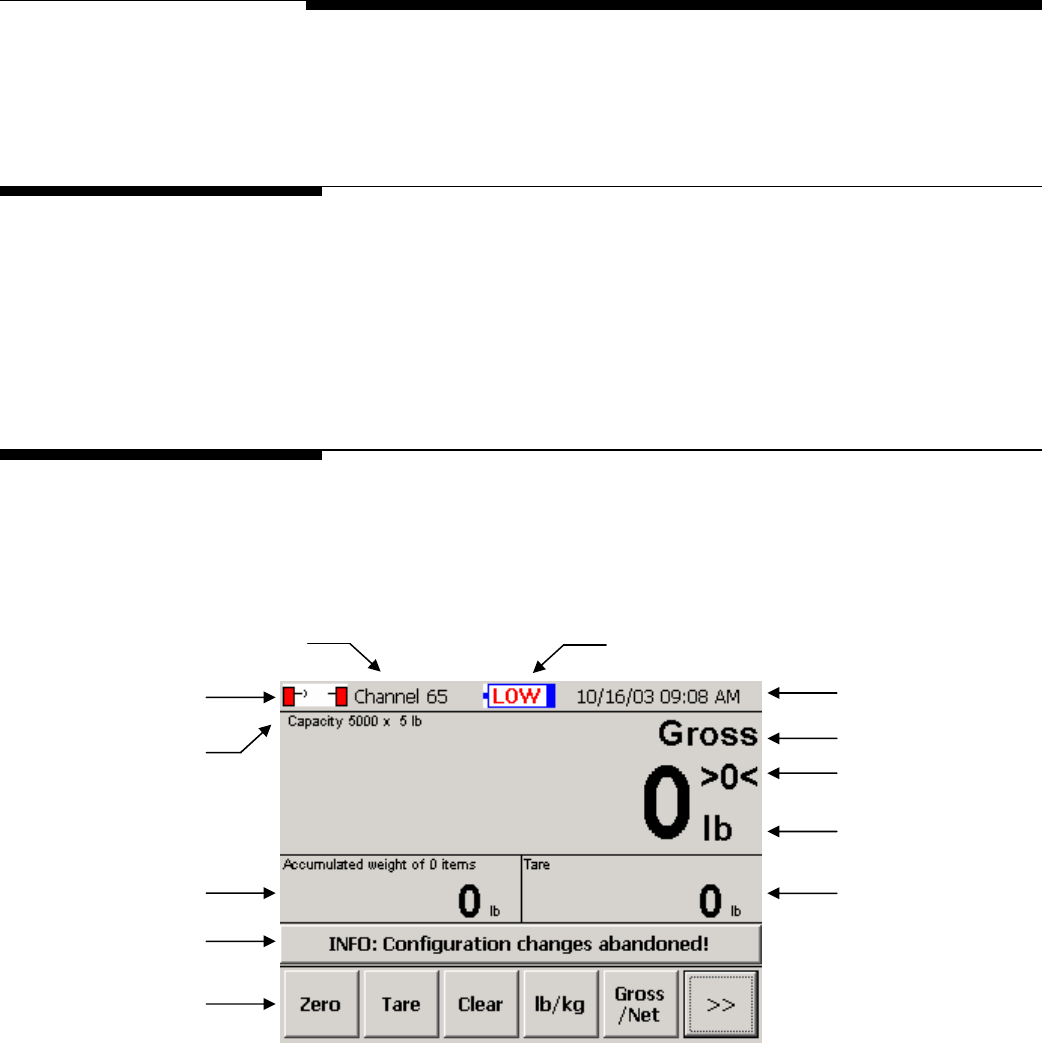
Weighing Screen
All weighing operations can be performed from the scale controller’s main weighing
screen. In addition to displaying current weight data, the screen provides push buttons
used to perform weighing operations and to enter setup mode.
Radio Channel Battery Level Indicator
Time and Date
Radio Communication
Weighing Mode
Maximum Capacity
and Increment Size “~” Indicates when
Scale is in Motion
Weight Reading
Accumulated Weight Tare Weight
Message Bar
Push Buttons
Figure 3-1: Main Weighing Screen
Radio Communication: When the indicator is green, the radios are communicating.
When it is red, there is no communication.
Battery Level Indicator: The blue color indicates the battery level. The indicator will
display a warning message when the battery level is low and when the battery needs to
be changed. The battery discharge cradle has a low-voltage cutoff that shuts off power
to the scale carriage when the battery voltage drops to the “change battery” level
(approximately 10.5 volts).
(3/05) 3-1
METTLER TOLEDO MCFA Forklift Scale Service Manual
Push Buttons The push buttons at the bottom of the main weighing screen are used to perform
weighing functions and to enter setup mode.
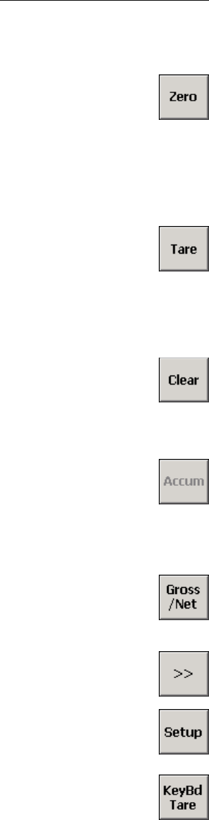
Zero
The Zero button is used to zero the scale manually. This feature can be used if the
weight reading on the screen does not return to zero when all load has been removed
from the scale. In order for this button to zero the scale manually, (1) the scale must be
in gross weighing mode and (2) the weight reading on the screen must be within the
range specified in the manual range setup feature. The scale also includes an automatic
zero maintenance (AZM) feature. When AZM is enabled, the scale will be zeroed
automatically if the weight reading is within a specified range.
Tare
The Tare button is used to assign the weight that is currently on the scale as a tare
weight. The tare weight is the weight of an empty pallet or container. It is subtracted
from the gross weight (weight of the loaded pallet or container) to determine the net
weight (weight of the item on the pallet or the material in the container). The tare weight
will be displayed in the Tare field. This button will work only if push button tare is
enabled in scale setup.
Clear
The Clear button is used to remove a tare weight reading or accumulated weight
reading that is displayed on the screen. To remove a tare weight reading, touch the
Clear button and then touch the Tare button. To remove an accumulated weight
reading, touch the Clear button and then touch the Accum button.
Accumulator
The Accum button is used to accumulate a series of weights and sum them to calculate
a total weight. When you touch the Accum button, the gross or net weight that is
displayed on the screen will be added to the weight reading in the Accumulated Weight
field. This button will be available only if basic accumulate is enabled in application
setup.
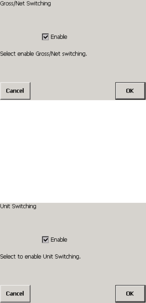
Gross/Net
The Gross/Net button is used to switch between gross and net weight readings on the
screen. In order to switch to a net weight reading, you must first assign a tare weight.
This button will work only if gross/net switching is enabled in scale setup.
>>
The double arrow button is used to display additional push buttons on the screen.
Setup
The Setup button is used to enter setup mode on the controller. For an explanation of
the setup features and how to use them, refer to the “Scale Setup” section of this
manual.
Keyboard Tare
The Keybd Tare button is used to enter a tare weight manually. The tare weight is the
weight of an empty pallet or container. It is subtracted from the gross weight (weight of
the loaded pallet or container) to determine the net weight (weight of the item on the
pallet or the material in the container). When you touch the Keybd Tare button, a
keypad will appear on the screen. Type the tare weight by touching the numerical keys
on the keypad. Then touch the Enter button. The tare weight will be displayed in the Tare
field. This button will work only if keyboard tare is enabled in scale setup.
(3/05)
3-2
Chapter 3: Scale Operations
Weighing Operations
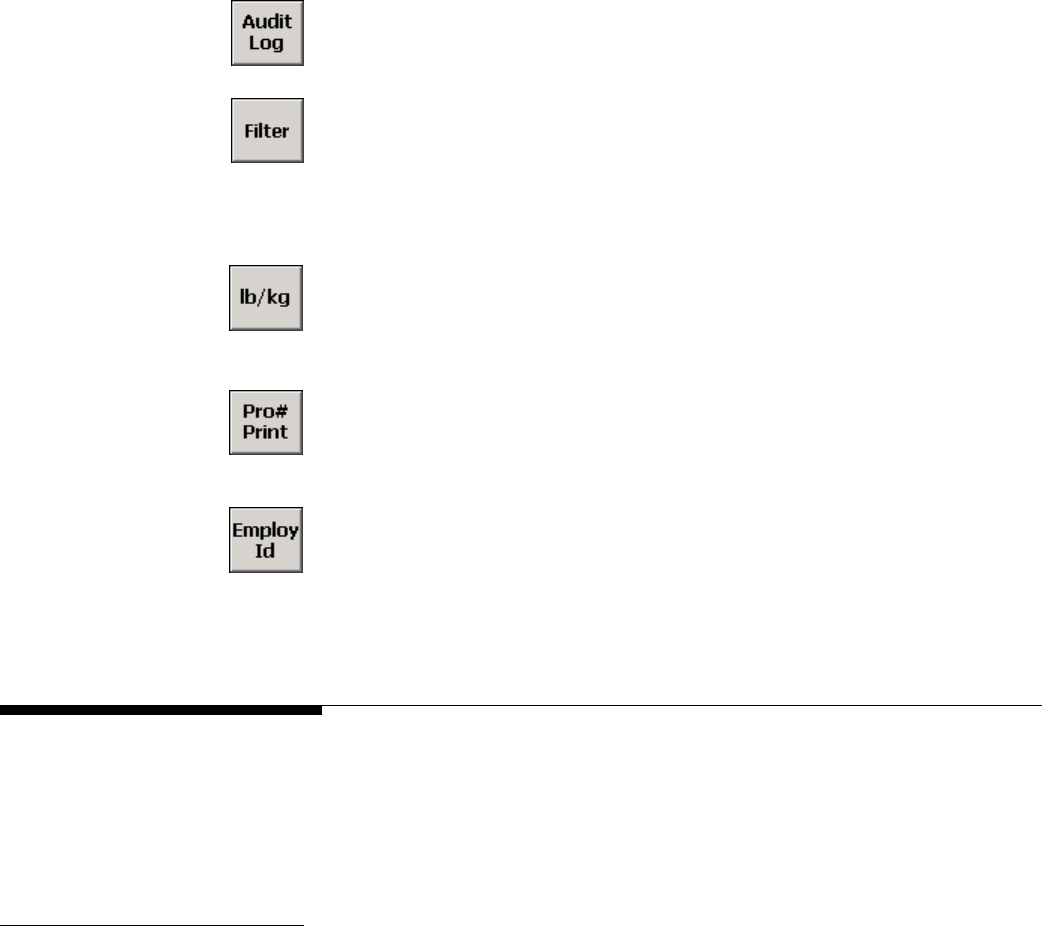
Audit Log
The Audit Log button is used to view the scale’s log that is required for Weights and
Measures audits. The log lists all calibration and configuration changes.
Filter
The Filter button is used to adjust the vibration filtering for the scale. It lets you adjust
filtering without entering setup mode. You can disable filtering or specify a filtering level
(Light, Lt/Med, Medium, Med/Hvy, or Heavy). Any changes made using this button will
be lost when the scale controller is shut off. At power-up, the scale will revert to the filter
settings that are specified in setup mode.
lb/kg
The lb/kg button is used to switch between weight readings in pounds and kilograms. It
changes the unit of measure for all weights displayed on the screen. This button will
work only if unit switching is enabled in scale setup.
Pro Number
The Pro# Print button is used to enter a shipping number for a SmartWeigh transaction
and create a record of the transaction. This button will be available only if advanced
accumulate is enabled in application setup.
Employee ID
The Employ ID button is used to enter an Employee ID for a SmartWeigh transaction.
This button will be available only if advanced accumulate is enabled in application
setup. When you touch the button, a keypad will appear on screen. Type the Employee
ID by touching the keys on the keypad. Then touch the Enter button.
Weighing Operations
This section describes the scale’s basic weighing operations, which are performed from
the controller’s main weighing screen. You can display a gross weight, use a tare
weight to determine a net weight, and use the accumulator to calculate the sum of a
series of gross or net weights.
Gross Weighing Use the following procedure to find the gross weight of an item:
1.
Lift the item with the forklift.
2.
The gross weight will be displayed in the Weight field.
(3/05) 3-3

METTLER TOLEDO MCFA Forklift Scale Service Manual
Net Weighing with Push
Button Tare Push button tare must be enabled in scale setup. Use the following procedure to find the
net weight of an item:
1.
Lift the empty pallet (or container) with the forklift.
2.
The weight will be displayed as a gross weight in the Weight field.
3.
Touch the Tare button.
4.
The weight of the pallet (or container) will be displayed in the Tare field. The
reading in the Weight field will change to zero.
5.
Lift the loaded pallet (or container) with the forklift. You can remove the pallet (or
container) from the forklift to fill it or fill it while it is on the scale.
6.
The net weight of the item will be displayed in the Weight field. If you wish to view
the gross weight of the loaded pallet (or container), touch the Gross/Net button.
7.
If auto clear is enabled, the gross/net weight and tare weight readings on the screen
will automatically return to zero when the load is removed from the scale.
Otherwise, the tare weight will remain on the screen and can be used to weigh
another loaded pallet (or container). To clear the tare weight, touch the Clear button
and then the Tare button.
Net Weighing with
Keyboard Tare Keyboard tare must be enabled in scale setup. Use the following procedure to find the
net weight of an item:
1.
Lift the loaded pallet (or container) with the forklift.
2.
The weight will be displayed as a gross weight in the Weight field.
3.
Touch the Keybd Tare button.
4.
A keyboard will appear on the screen. Type in the tare weight of the pallet (or
container) by touching the numerical keys on the keyboard. When the correct tare
weight is displayed in the keyboard’s data field, touch the Enter button.
5.
The net weight of the item will be displayed in the Weight field. If you wish to view
the gross weight of the loaded pallet (or container), touch the Gross/Net button.
The tare weight will be displayed in the Tare field.
6.
If auto clear is enabled, the gross/net weight and tare weight readings on the screen
will automatically return to zero when the load is removed from the scale.
Otherwise, the tare weight will remain on the screen and can be used to weigh
another loaded pallet (or container). To clear the tare weight, touch the Clear button
and then the Tare button.
NOTE: You can also use keyboard tare to enter a tare weight before lifting the loaded
pallet (or container) with the forklift.
(3/05)
3-4

Chapter 3: Scale Operations
Weighing Operations
Accumulating Gross
Weights Basic accumulate must be enabled in application setup. Use the following procedure to
accumulate gross weights:
1.
Lift an item with the forklift.
2.
The gross weight will be displayed in the Weight field.
3.
Touch the Accum button.
4.
The gross weight of the item will be displayed in the Accumulated Weight field. The
text above the field will indicate the number of loads that have been accumulated:
“Accumulated weight of 1 item.”
5.
Remove the item from the scale, and then lift the next item.
6.
The gross weight of the item currently on the scale will be displayed in the Weight
field.
7.
Touch the Accum button.
8.
The gross weight of the item will be added to the weight displayed in the
Accumulated Weight field. The text above the field will indicate the number of loads
that have been accumulated: “Accumulated weight of 2 items.”
9.
Repeat Steps 5 to 8 for each additional item to be weighed.
10.
When you have finished accumulating weights, remove the load from the forklift. To
clear the accumulated weight, touch the Clear button and then the Accum button.
Accumulating Net Weights Basic accumulate must be enabled in application setup. Use the following procedure to
accumulate net weights:
1.
Display the net weight to be accumulated:
• If you are using push button tare, lift the empty pallet (or container) and touch
the Tare button. Then lift the loaded pallet (or container).
• If you are using keyboard tare, lift the loaded pallet (or container) and touch
the Keybd Tare button. Then enter the tare weight manually.
2.
Touch the Accum button.
3.
The net weight of the item will be displayed in the Accumulated Weight field. The
text above the field will indicate the number of loads that have been accumulated:
“Accumulated weight of 1 item.”
4.
Remove the item from the scale.
5.
Display the next net weight to be accumulated:
• If you are using pushbutton tare, lift the empty pallet (or container) and touch
the Tare button. Then lift the loaded pallet (or container).
• If you are using keyboard tare, lift the loaded pallet (or container) and touch
the Keybd Tare button. Then enter the tare weight manually.
6.
Touch the Accum button.
(3/05) 3-5
METTLER TOLEDO MCFA Forklift Scale Service Manual
7.
The net weight of the item will be added to the weight displayed in the Accumulated
Weight field. The text above the field will indicate the number of loads that have
been accumulated: “Accumulated weight of 2 items.”
8.
Repeat Steps 4 to 7 for each additional item to be weighed.
9.
When you have finished accumulating weights, remove the load from the forklift. To
clear the accumulated weight, touch the Clear button and then the Accum button.
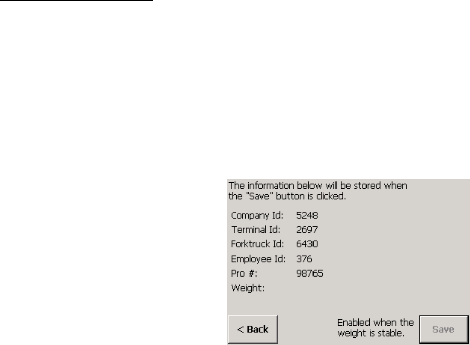
SmartWeigh Transactions The SmartWeigh option allows you to create records of weighing transactions. To use
the SmartWeigh option, you must enable advanced accumulate in application setup.
Use the following procedure to process a SmartWeigh transaction:
1.
Lift the item with the forklift.
2.
Touch the Employ ID button and then use the keypad to enter an Employee ID.
3.
Touch the Pro# Print button and then use the keypad to enter a Pro number.
4.
The SmartWeigh information screen will be displayed. It lists the weight and other
information about the transaction. Touch the Save button to save a record of the
transaction in a computer file.
(3/05)
3-6
Chapter 4: Scale Setup
Setup Screens
4
Scale Setup
Setup Screens
The scale controller’s touch screen provides access to the scale’s setup features. These
allow you to calibrate the scale, change how the scale operates, assign passwords, set
communication parameters, and perform diagnostic tests.
To use the scale’s setup features, touch the Setup button on the scale controller’s main
weighing screen. If security-level passwords have been assigned, you will be prompted
to enter a password.
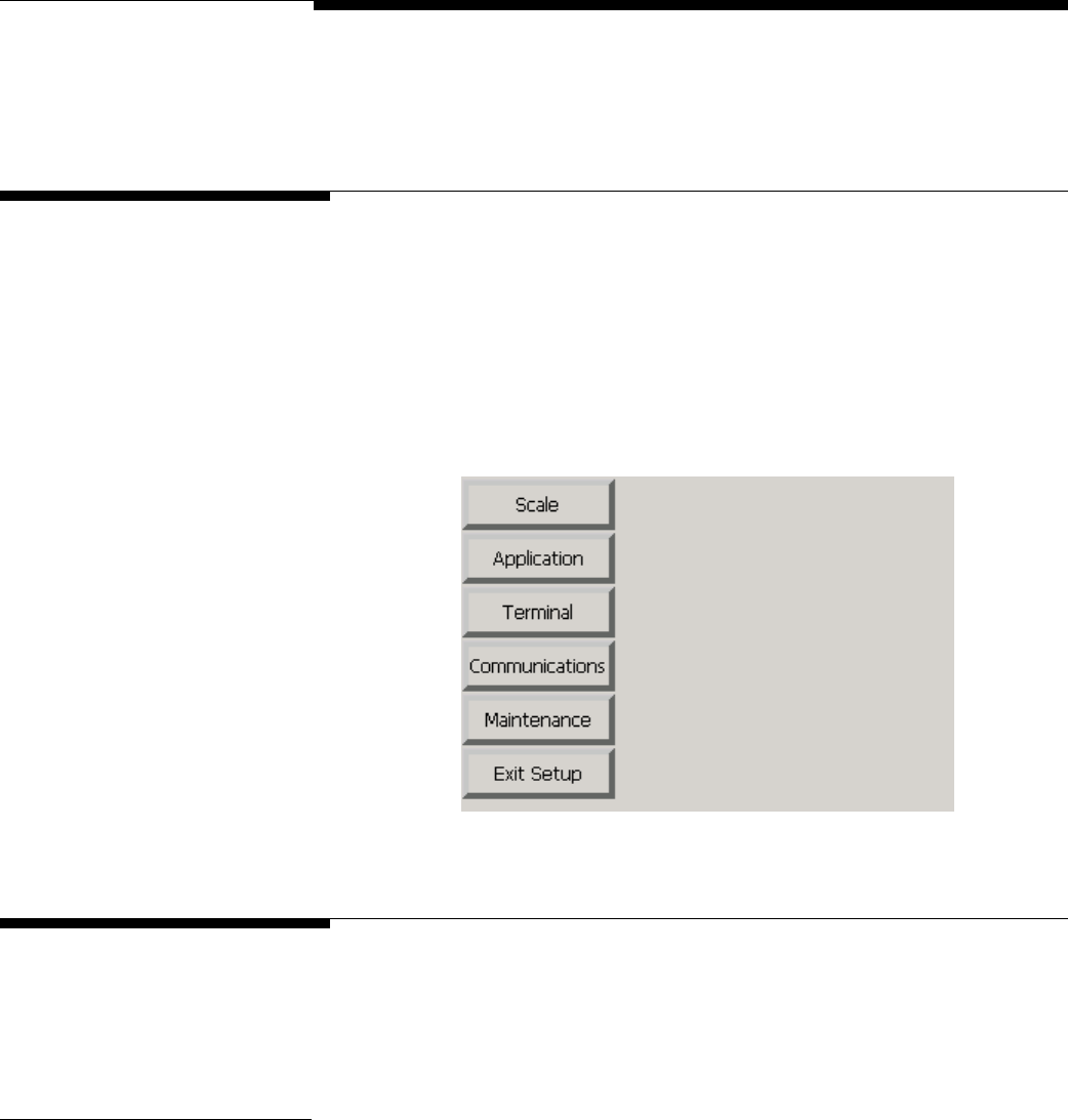
Scale
The scale setup features are used to calibrate the scale and adjust the settings for the
scale’s weighing functions. Touch the Scale button to display buttons for the individual
scale setup features.
Filter Filtering is used to compensate for environmental disturbances such as vibration and
noise. Touch the Filter button to access the filtering features.
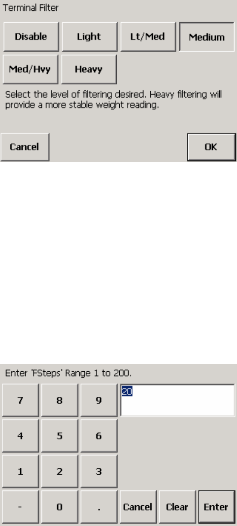
Terminal Filter
You can select a filtering level for the scale. Heavy filtering will provide a more stable
weight reading, but it can cause the scale to take longer to stabilize. The default setting
is Medium.
1.
Touch the Terminal Filter button.
(3/05) 4-1
METTLER TOLEDO MCFA Forklift Scale Service Manual
2.
Touch a button to disable filtering or to select a filtering level (Light, Lt/Med,
Medium, Med/Hvy, or Heavy).
3.
Touch the OK button to confirm your selection or the Cancel button to cancel any
changes that you made.
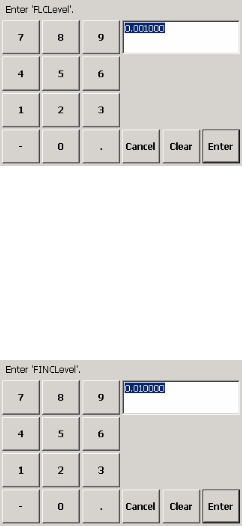
Fsteps
The FSteps feature sets the filter constant used for on-board digital filtering. This is a
simple recursive filter that determines the filtered value by averaging a number (the
FSteps setting) of the most recent samples. The default setting is 20. A higher number
results in heavier filtering; a lower number results in lighter filtering. This constant is set
at the factory and should not need to be adjusted.
1.
Touch the FSteps button to display a keypad on the screen.
2.
Type a number in the data field by touching the numeric keys on the keypad. Valid
Fsteps settings are 1 to 200. Touch the Clear button if you wish to clear the data
field and start over.
3.
Touch the Enter button to confirm your selection or the Cancel button to cancel any
changes that you made.
(3/05)
4-2
Chapter 4: Scale Setup
Scale
FLCLevel
The FLCLevel is another constant used for on-board digital filtering. It represents the
input step change for the load cells that will restart the filter averaging. The default
setting is 0.001. This constant is set at the factory and should not need to be adjusted.
1.
Touch the FLCLevel button to display a keypad on the screen.
2.
Type a number in the data field by touching the numeric keys on the keypad. Valid
FLCLevel settings are 0.01 to 0.0001. Touch the Clear button if you wish to clear
the data field and start over.
3.
Touch the Enter button to confirm your selection or the Cancel button to cancel any
changes that you made.
FINCLevel
The FINCLevel is another constant used for on-board digital filtering. It represents the
input step change for the inclinometers that will restart the filter averaging. The default
setting is 0.01. This constant is set at the factory and should not need to be adjusted.
1.
Touch the FINCLevel button to display a keypad on the screen.
2.
Type a number in the data field by touching the numeric keys on the keypad. Valid
FINCLevel settings are 0.1 to 0.001. Touch the Clear button if you wish to clear the
data field and start over.
(3/05) 4-3
METTLER TOLEDO MCFA Forklift Scale Service Manual
3.
Touch the Enter button to confirm your selection or the Cancel button to cancel any
changes that you made.
Tare The following tare setup features allow you to enable or disable functions for entering
and clearing tare weights. Touch the Tare button to access the features.
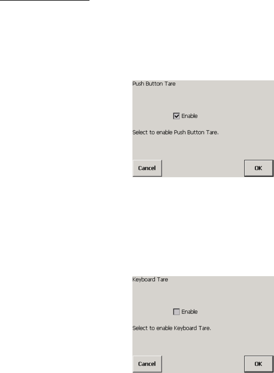
Push Button Tare
Push button tare allows you to assign the weight that is currently on the scale as the tare
weight by touching the Tare button on the weighing screen. The default setting is Enabled.
1.
Touch the Push Button button.
2.
Touch the check box to place a check mark in it (enabling the function) or to
remove a check mark (disabling the function).
3.
Touch the OK button to confirm your selection or the Cancel button to cancel any
changes that you made.
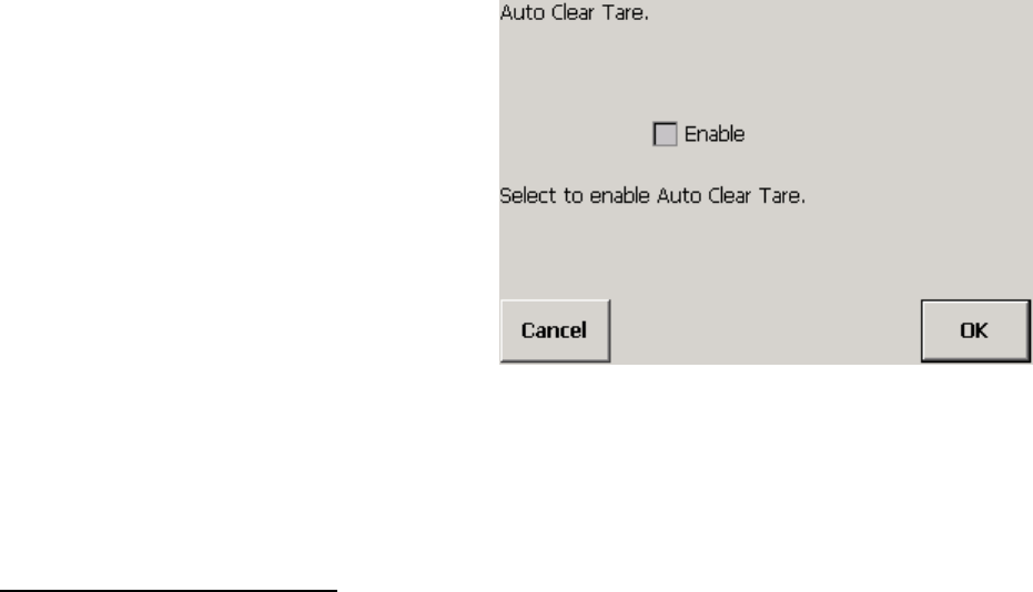
Keyboard Tare
Keyboard tare allows you to enter a tare weight manually by touching the Keybd Tare
button on the weighing screen and then typing a weight. The default setting is Disabled.
1.
Touch the Keyboard button.
(3/05)
4-4
Chapter 4: Scale Setup
Scale
2.
Touch the check box to place a check mark in it (enabling the function) or to
remove a check mark (disabling the function).
3.
Touch the OK button to confirm your selection or the Cancel button to cancel any
changes that you made.
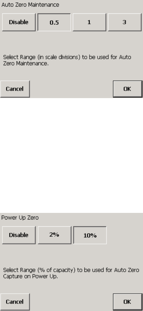
Auto Clear
Auto clear automatically clears the tare weight from the terminal when a load is removed
from the scale (the weight reading returns to zero). The default setting is Disabled.
1.
Touch the Auto Clear button.
2.
Touch the check box to place a check mark in it (enabling the function) or to
remove a check mark (disabling the function).
3.
Touch the OK button to confirm your selection or the Cancel button to cancel any
changes that you made.
Zero The zero setup features allow you to specify weight ranges for zeroing the scale. The
zeroing function resets the weight reading for the empty scale to zero. It is used when
temperature changes or material built up on a scale prevents the weight reading from
returning to zero when the scale is emptied. Touch the Zero button to access the
features.
Automatic Zero Maintenance (AZM)
AZM automatically adjusts the scale’s weight reading to zero when the load is removed
from the scale. In order for AZM to zero the scale, the weight reading on the scale must
be within the range specified. The default setting is ±0.5 division (increment).
1.
Touch the AZM button.
(3/05) 4-5
METTLER TOLEDO MCFA Forklift Scale Service Manual
2.
Touch a button to disable AZM or to select an AZM range (±0.5, ±1, or ±3
divisions).
3.
Touch the OK button to confirm your selection or the Cancel button to cancel any
changes that you made.
Power-Up Zero
Power-up zero automatically adjusts the scale’s weight reading to zero when the
controller is powered up. In order to zero the scale automatically at power-up, the
weight reading on the scale must be within the range specified. The default setting is
±10% of scale capacity.
1.
Touch the Power Up button.
2.
Touch a button to disable power-up zero or to select a range (2% or 10% of scale
capacity).
3.
Touch the OK button to confirm your selection or the Cancel button to cancel any
changes that you made.
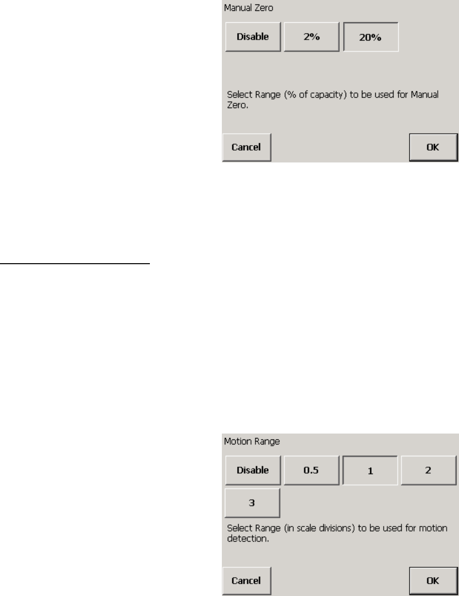
Manual Zero Range
Manual zero allows you to zero the scale by using the Zero button on the weighing
screen. In order for the manual zero function to zero the scale, the weight reading on the
scale must be within the range specified. The default setting is ±20% of scale capacity.
1.
Touch the Manual Range button.
(3/05)
4-6
Chapter 4: Scale Setup
Scale
2.
Touch a button to disable manual zero or to select a range (2% or 20% of scale
capacity).
3.
Touch the OK button to confirm your selection or the Cancel button to cancel any
changes that you made.
Stability The stability settings allow you to specify the conditions that the scale must meet in
order to be considered stable. Touch the Stability button to access the features.
Motion Range
Motion range allows you to select the range to be used for motion detection. For the
scale to be considered stable, it must produce several consecutive weight readings
within that range. The default setting is ±1 division (increment). When the scale is in
motion, a “~” will be displayed next to the weight reading on the weighing screen. The
zero, tare, and print functions cannot be used when the scale is in motion.
1.
Touch the Motion Range button.
2.
Touch a button to disable motion detection or to select a motion detection range
(0.5, 1, 2, or 3 divisions).
(3/05) 4-7
METTLER TOLEDO MCFA Forklift Scale Service Manual
3.
Touch the OK button to confirm your selection or the Cancel button to cancel any
changes that you made.
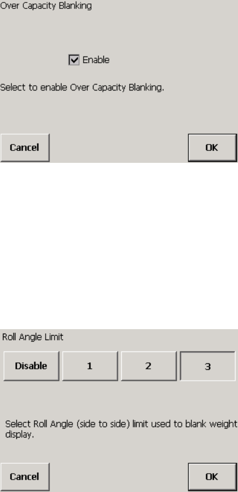
Over Capacity
If over capacity is enabled, the display will go blank when the weight on the scale
exceeds the maximum scale capacity. The default setting is Enabled.
1.
Touch the Over Capacity button.
2.
Touch the check box to place a check mark in it (enabling the function) or to
remove a check mark (disabling the function).
3.
Touch the OK button to confirm your selection or the Cancel button to cancel any
changes that you made.
Roll Angle Limit
The roll angle limit is the maximum side-to-side angle for the mast. If the mast roll
exceeds that angle, the weight display will go blank. The default setting is 3 degrees.
1.
Touch the Roll Angle Limit button.
2.
Touch a button to disable roll angle blanking or to select a maximum mast roll
angle (1, 2, or 3 degrees).
(3/05)
4-8
Chapter 4: Scale Setup
Scale
3.
Touch the OK button to confirm your selection or the Cancel button to cancel any
changes that you made.
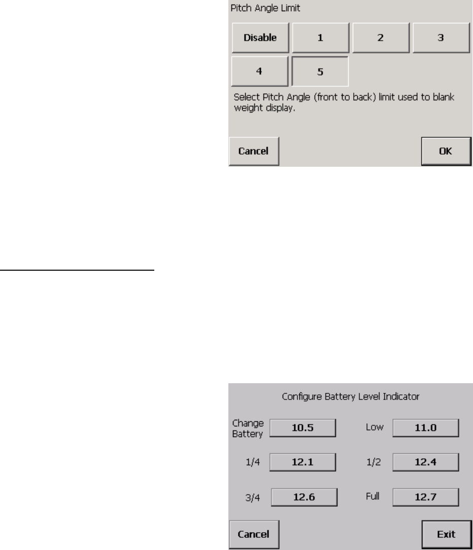
Pitch Angle Limit
The pitch angle limit is the maximum front-to-back angle for the mast. If the mast pitch
exceeds that angle, the weight display will go blank. The default setting is 5 degrees.
1.
Touch the Pitch Angle Limit button.
2.
Touch a button to disable pitch angle blanking or to select a maximum mast pitch
angle (1, 2, 3, 4, or 5 degrees).
3.
Touch the OK button to confirm your selection or the Cancel button to cancel any
changes that you made.
Battery Levels This screen shows the actual voltage levels that correspond to the battery level indicator
settings on the main weighing screen. The default voltage levels were determined at the
factory and should not need to be changed. Do not use a battery if the voltage level is
below 10.5 volts.
1.
Touch the Battery Levels button to display the current battery voltage settings.
(3/05) 4-9
METTLER TOLEDO MCFA Forklift Scale Service Manual
2.
If you wish to change a voltage setting, touch the button that shows the current
setting. A keypad will be displayed on the screen.
3.
Type a voltage level in the data field by touching the numeric keys on the keypad.
Touch the Clear button if you wish to clear the data field and start over.
4.
Touch the Enter button to confirm your selection or the Cancel button to cancel any
changes that you made.
5.
Touch the Exit button to enter the settings shown on the screen and close the
screen. Touch the Cancel button to cancel any changes that you made.
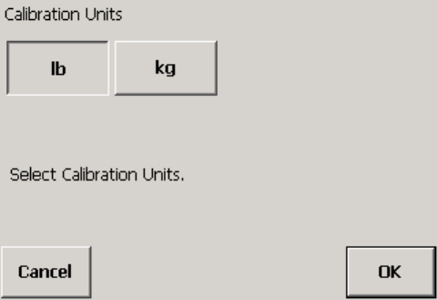
Units
Select the weight unit to be used for the scale (pounds or kilograms). This calibration
unit will be used when the scale is first powered up. If you change the calibration unit,
you must recalibrate the scale. The default setting is pounds (lb).
1.
Touch the Units button.
2.
Touch a button to select the desired weight unit (lb or kg).
3.
Touch the OK button to confirm your selection or the Cancel button to cancel any
changes that you made.
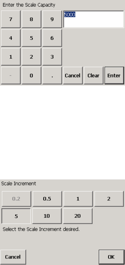
Capacity
Enter the total capacity of the scale. The capacity must be entered in the calibration unit
specified for the scale. The default setting is 5000 lb (or 2000 kg).
1.
Touch the Capacity button to display a keypad on the screen.
(3/05)
4-10
Chapter 4: Scale Setup
Scale
2.
Type a weight in the data field by touching the numeric keys on the keypad. Touch
the Clear button if you wish to clear the data field and start over.
3.
Touch the Enter button to confirm your selection or the Cancel button to cancel any
changes that you made.
Increment
Select the increment (minimum weight unit to be displayed by the scale). The increment
must correspond to the calibration unit specified for the scale. Larger increments will
result in less weight precision but quicker weighing time. The default setting is 5 lb.
1.
Touch the Increment button.
2.
Touch a button to select an increment size (0.2, 0.5, 1, 2, 5, 10, or 20).
3.
Touch the OK button to confirm your selection or the Cancel button to cancel any
changes that you made.
Gross/Net
Gross/net switching enables the controller to toggle between gross and net weight. Net
weight will be available only after a tare weight has been established. The default setting
is Enabled.
1.
Touch the Gross/Net button.
(3/05) 4-11
METTLER TOLEDO MCFA Forklift Scale Service Manual
2.
Touch the check box to place a check mark in it (enabling the function) or to
remove a check mark (disabling the function).
3.
Touch the OK button to confirm your selection or the Cancel button to cancel any
changes that you made.
Unit Switching
Unit switching enables the controller to toggle between lb and kg. The default setting is
Enabled.
1.
Touch the Unit Switching button.
2.
Touch the check box to place a check mark in it (enabling the function) or to
remove a check mark (disabling the function).
3.
Touch the OK button to confirm your selection or the Cancel button to cancel any
changes that you made.
(3/05)
4-12
Chapter 4: Scale Setup
Scale
Calibration Only qualified service technicians should calibrate the scale. Touch the Calibration
button to access the calibration features.
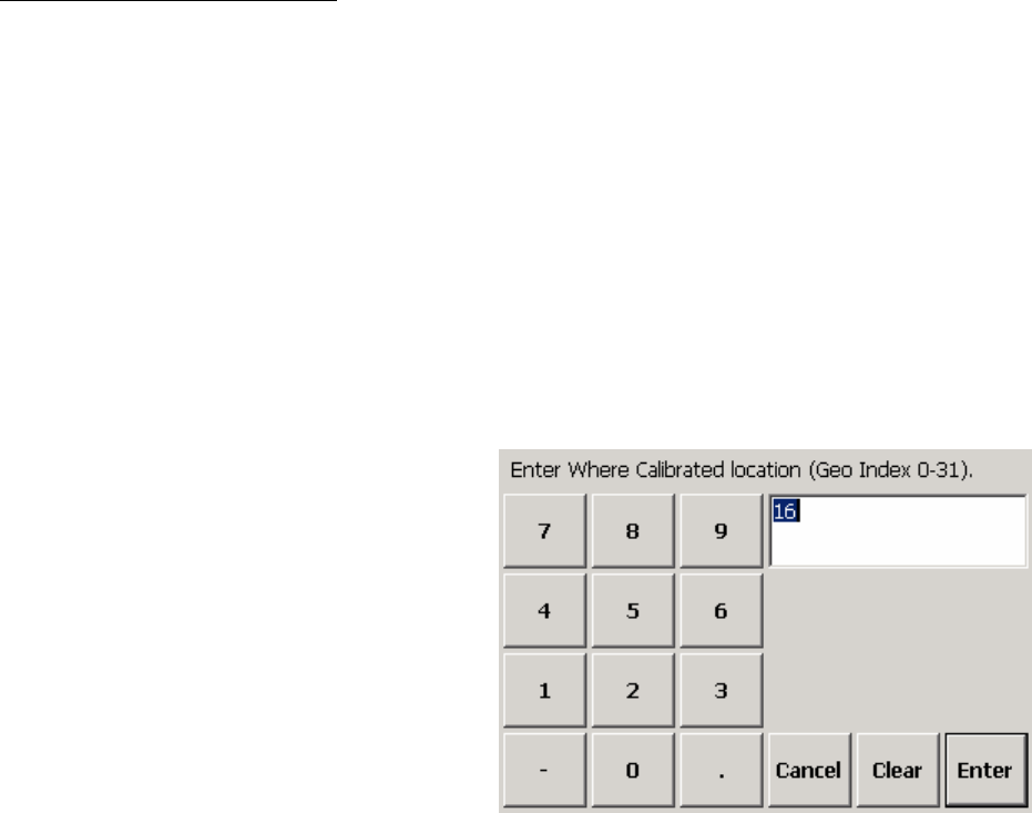
Where Calibrated
The scale controller can compensate for variations caused by gravitational forces. This
feature shows the gravity factor (geo index) for the location where the scale was
calibrated. The geo index is set to 16 at the factory (16 is the geo index for
Worthington, Ohio, USA). Do not change this geo index unless you perform a full
recalibration of the scale.
If you recalibrate the scale, use the following procedure to set the geo index for the
calibration location.
1.
Touch the Where Calibrated button to display a keypad on the screen.
2.
Type a number in the data field by touching the numeric keys on the keypad (the
range is 0 to 31). Touch the Clear button if you wish to clear the data field and
start over.
3.
Touch the Enter button to confirm your selection or the Cancel button to cancel any
changes that you made.
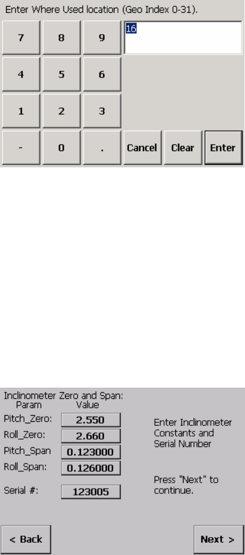
Where Used
This feature shows the geo index for the location where the scale will be used. You can
change the setting to compensate for local gravitational forces. To determine the geo
index for a location, refer to Chapter 10. You must know the geographical coordinate for
the location and the elevation above sea level.
1.
Touch the Where Used button to display a keypad on the screen.
(3/05) 4-13
METTLER TOLEDO MCFA Forklift Scale Service Manual
2.
Type a number in the data field by touching the numeric keys on the keypad (the
range is 0 to 31). Touch the Clear button if you wish to clear the data field and
start over.
3.
Touch the Enter button to confirm your selection or the Cancel button to cancel any
changes that you made.
Inclinometer
This feature is used to set the pitch and roll reference angles. The serial number, initial
zero values, and initial span values are entered at the factory to match data provided by
the manufacturer of the inclinometer.
1.
Touch the Inclinometer button to display the serial number, zero values, and span
values for the inclinometer. A value can be changed manually by touching the
button for the value and then using the keypad to enter a new value.
2.
Park the forklift on a level surface, remove all load from the forks, raise the forks off
the ground, set the mast to the vertical position, and shut off the forklift’s motor.
3.
Touch the Next button to continue (or touch the Back button to go back a step).
The screen will display the active and indicated pitch and roll reference angles.
4.
Touch the Next button to update the values (or touch the Back button to go back a
step). The system will count down as it updates the values. The new pitch and roll
reference angles will be displayed.
5.
Touch the Finish button to accept the new values.
(3/05)
4-14
Chapter 4: Scale Setup
Scale
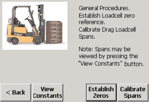
Loadcell
This feature is used to set spans for the chain load cells, to calibrate spans for the drag
load cells, and to establish zero constants for all load cells. Touch the Loadcell button.
To view the active load cell span constants, touch the View Constants button. A value
can be changed manually by touching the button for the value and then using the
keypad to enter a new value. The values for the chain load cells (LC3 and LC4) are set
by default to 2500 and should not be changed. To close the view constants screen,
touch the Back button. Changes will be lost if you exit setup without saving them.
Calibrate spans for the drag load cells:
1.
Touch the Calibrate Spans button to calibrate span values for the drag load cells.
2.
Park the forklift truck on a level surface, remove all load from the forks, set the mast
to the vertical position, and raise the forks slightly more than 15 inches off the
ground.
3.
Position a block 15 inches high under the bottom roller on each side of the scale
carriage. Lower the carriage onto the blocks until the chains are slack, and then
raise the carriage off the blocks (repeat this several times to exercise the scale).
4.
With the carriage raised off the blocks, shut off the forklift truck’s motor. Wait about
15 seconds for the scale to stabilize.
5.
Touch the Next button to capture zero. The system will count down as it updates
the values.
6.
Lower the carriage onto the blocks, and wait about 15 seconds for the scale to
stabilize.
7.
Touch the Next button to calibrate the span values. The system will count down as
it updates the values. The new drag load cell span constants will then be
displayed.
8.
Touch the Finish button to accept the new span values.
9.
Raise the carriage and remove the blocks.
Establish zero for the scale:
1.
Touch the Establish Zeros button to display the load cell zero constants.
2.
Touch the Next button to update the constants. The system will count down as it
updates the values.
(3/05) 4-15
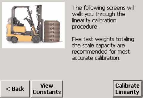
METTLER TOLEDO MCFA Forklift Scale Service Manual
3.
The new zero constants will be displayed. A value can be changed manually by
touching the button for the value and then using the keypad to enter a new value.
Touch the Finish button to save the new constants, or touch the Back button to
close the screen without saving the new constants.
Linearity
This feature is used to calibrate the scale’s linearity. We recommend using five test
weights of 1,000 lb each. You can also calibrate linearity using test weights equal to
one half the scale capacity and full scale capacity. Touch the Linearity button.
To view the active linearity constants, touch the View Constants button. A value can be
changed by touching the button for the value and then using the keypad to enter a new
value. To close the view constants screen without making any changes, touch the Back
button.
Check the scale’s linearity to determine if calibration is needed:
• Park the forklift truck on a level surface, raise the forks 12 to 15 inches off the
ground, set the mast to the vertical position, and shut off the forklift truck’s motor.
Place a pallet on the forks, and use the weight of the pallet as the tare weight.
• Record the net weight with no test weight on the scale. Then add the five test
weights one at a time, recording the net weight after each test weight is added. You
should have weight readings for the following test weights: 0, 1000, 2000, 3000,
4000, and 5000 lb. Then remove the test weights from the scale one at a time,
recording the net weight each time you remove a test weight.
If the weight readings are out of tolerance, perform the following calibration procedure:
1.
Park the forklift truck on a level surface, place a pallet on the forks, raise the forks
12 to 15 inches off the ground, set the mast to the vertical position, and shut off the
forklift truck’s motor.
2.
Touch the Calibrate Linearity button to display the linearity test setup. For the
default test setup, all six boxes will be checked and the following weight values will
be listed on the buttons next to the boxes: 0, 1000, 2000, 3000, 4000, and
5000. If you plan to use a different range of weights, reconfigure the test setup to
match those weights. You can select or deselect a step by touching the check box.
You can change a weight value by touching the button to open a keypad that will
allow you to enter a new weight value. When the correct weight values are
displayed, touch the Next button to continue.
(3/05)
4-16
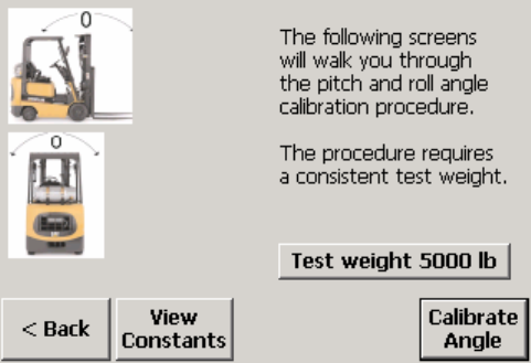
Chapter 4: Scale Setup
Scale
3.
With zero test weight on the scale, touch the Next button. The system will count
down as it updates the values.
4.
Add test weight so that the total weight on the scale equals 1,000 lb, allow the
scale to stabilize, and then touch the Next button. The system will count down as it
updates the values.
5.
Add test weight so that the total weight on the scale equals 2,000 lb, allow the
scale to stabilize, and then touch the Next button. The system will count down as it
updates the values.
6.
Add test weight so that the total weight on the scale equals 3,000 lb, allow the
scale to stabilize, and then touch the Next button. The system will count down as it
updates the values.
7.
Add test weight so that the total weight on the scale equals 4,000 lb, allow the
scale to stabilize, and then touch the Next button. The system will count down as it
updates the values.
8.
Add test weight so that the total weight on the scale equals 5,000 lb, allow the
scale to stabilize, and then touch the Next button. The system will count down as it
updates the values.
9.
Touch the Compute button to calculate the new linearity constants.
10.
The new linearity constants will be displayed. Touch the Finish button to accept the
new constants.
Angle
The following screens will walk you through the procedure for calibrating pitch and roll
angles for the mast. This procedure will compensate for any variation in weight readings
that might occur when the mast is set at different angles. Touch the Angle button.
To view the active angle constants, touch the View Constants button. A value can be
changed manually by touching the button for the value and then using the keypad to
enter a new value. To close the view constants screen without making any changes,
touch the Back button.
Determine if angle calibration is needed by checking the scale’s accuracy with the mast
set at several angles. Use the same test weight for each mast setting. The recommended
test weight is full scale capacity (5,000 lb). To change the test weight amount, touch
the test weight button on the angle calibration screen and then use the keypad to enter a
new weight value.
(3/05) 4-17
METTLER TOLEDO MCFA Forklift Scale Service Manual
• Park the forklift truck on a level surface, set the mast to the vertical position, and
raise the forks 12 to 15 inches off the ground. The forklift truck’s motor should be
shut off when taking weight readings. Place a pallet on the forks, and zero the
scale. Place the test weight on the scale, and record the weight.
• Check the mast pitch: Remove the test weight, set the mast 5 degrees backward,
and zero the scale. Then place the test weight on the scale, and record the weight.
Remove the test weight, set the mast 5 degrees forward, and zero the scale. Then
place the test weight on the scale, and record the weight.
• Check the mast roll: Set the mast to the vertical position. Remove the test weight,
position the forklift truck on a ramp so that the mast is angled approximately 3
degrees to the right, and zero the scale. Then place the test weight on the scale,
and record the weight. Remove the test weight, position the forklift truck on a ramp
so that the mast is angled approximately 3 degrees to the left, and zero the scale.
Then place the test weight on the scale, and record the weight.
If the weight readings are out of tolerance, then calibrate the mast pitch angle or both
the mast pitch and mast roll angles. Use the following procedure to calibrate the mast
pitch angle:
1.
Park the forklift truck on a level surface, place a pallet on the forks, raise the forks
12 to 15 inches off the ground, set the mast to the vertical position, and shut off the
forklift truck’s motor.
2.
Touch the Calibrate Angle button.
3.
Touch the Next button. The system will count down as it updates the zero load
values.
4.
Add the test weight, allow the scale to stabilize, and then touch the Next button.
The system will count down as it updates the loaded values.
5.
Remove the test weight from the scale.
6.
Set the mast so that it is angled approximately 5 degrees backward. Shut off the
forklift truck’s motor.
7.
Touch the Next button. The system will count down as it updates the zero load
values.
8.
Add the test weight, allow the scale to stabilize, and then touch the Next button.
The system will count down as it updates the loaded values.
9.
Remove the test weight from the scale.
10.
Set the mast so that it is angled approximately 5 degrees forward. Shut off the
forklift truck’s motor.
11.
Touch the Next button. The system will count down as it updates the zero load
values.
12.
Add the test weight, allow the scale to stabilize, and then touch the Next button.
The system will count down as it updates the loaded values.
13.
Touch the Compute button to calculate the new pitch angle constants, or touch the
Continue button to continue calibrating both pitch and roll angles.
To calibrate the mast roll angle, continue with the following steps:
14.
Remove the test weight from the scale, and set the mast to the vertical position.
15.
Position the forklift truck on a ramp so that the mast is angled approximately 3
degrees to the right. Shut off the forklift truck’s motor.
(3/05)
4-18

Chapter 4: Scale Setup
Scale
16.
Touch the Next button. The system will count down as it updates the zero load
values.
17.
Add the test weight, allow the scale to stabilize, and then touch the Next button.
The system will count down as it updates the loaded values.
18.
Remove the test weight from the scale.
19.
Position the forklift truck on a ramp so that the mast is angled approximately 3
degrees to the left. Shut off the forklift truck’s motor.
20.
Touch the Next button. The system will count down as it updates the zero load
values.
21.
Add the test weight, allow the scale to stabilize, and then touch the Next button.
The system will count down as it updates the loaded values.
22.
Touch the Compute button to calculate the new pitch and roll angle constants.
23.
Touch the Finish button to accept the new constants.
Download Data
This feature downloads calibration constants from the controller. WARNING: This feature
will overwrite all calibrated data. The only reason to download the constants is if you
have replaced the circuit board in the telemetry enclosure.
1.
Touch the Download Data button. A window will open, explaining that updating the
constants might take 30 seconds and asking if you wish to continue.
2.
Touch the Update button to proceed with the download or the Cancel button to
keep the previous settings.
You will need to restart the scale controller to complete the procedure.
Factory Use The following features are to be used only at the METTLER TOLEDO factory. Touch the
Factory Use button to access the features.
Hardware Tests
Touch the Hardware Tests button to run the hardware tests. The controller will prompt
you to connect it to a manufacturing line PC and then prompt you to scan the 5-part
tag.
(3/05) 4-19
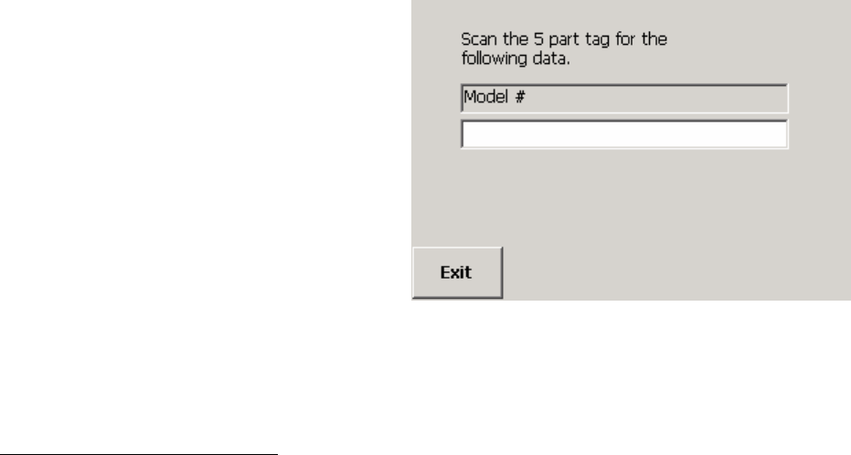
METTLER TOLEDO MCFA Forklift Scale Service Manual
Use a bar code scanner or keyboard to enter the data. Continue through the memory,
display resolution, display color, and calibrate touch tests. The tests are described in the
terminal and maintenance setup sections.
Reset The Reset button is used to reset the scale parameters to the factory default settings.
1.
Touch the Reset button.
2.
Touch the Reset button to restore the default scale parameters or the Cancel button
to keep the current settings.
(3/05)
4-20
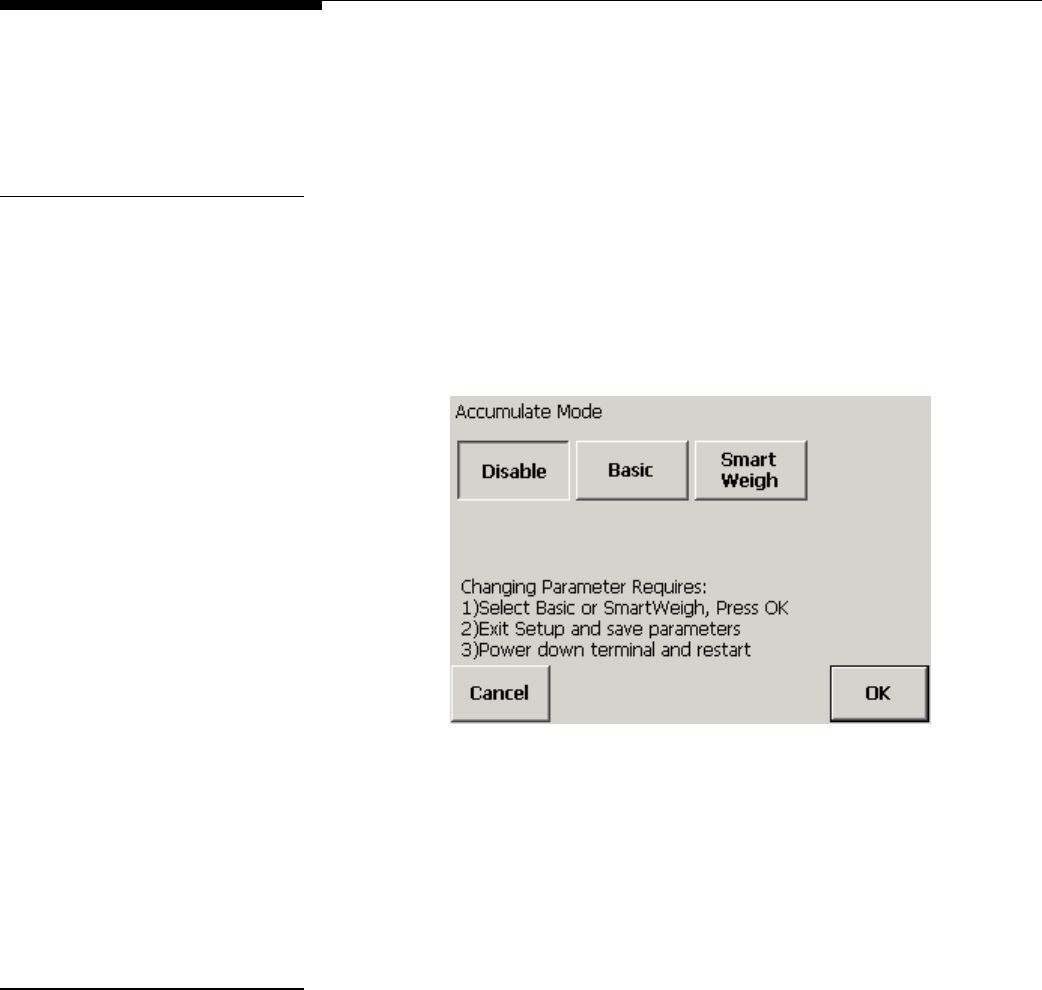
Chapter 4: Scale Setup
Application
Application
The application setup features are used to adjust the settings for the system’s
accumulator and SmartWeigh functions. Touch the Application button to display buttons
for the individual application setup features.
Accumulate The scale can accumulate a series of weight readings and sum the readings to
calculate a total weight. In order to use the accumulate function, you must enable it. The
default setting is Disabled.
1.
Touch the Accumulate button.
2.
Touch a button to disable accumulation, enable basic accumulation, or enable
SmartWeigh functions.
3.
Touch the OK button to confirm your selection or the Cancel button to cancel any
changes that you made.
If you select SmartWeigh or disable SmartWeigh by selecting one of the other options,
you will need to restart the controller in order for the change to take effect.
SmartWeigh Touch the SmartWeigh button to access the features.
Save Path
Enter the path to be used when saving SmartWeigh data to a file. The default path is
\DiskC\weighments.csv.
1.
Touch the Save Path button to open the save path screen.
(3/05) 4-21
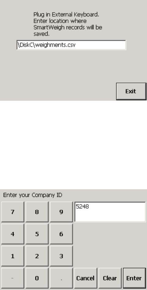
METTLER TOLEDO MCFA Forklift Scale Service Manual
2.
Type a path in the data field. You will need to connect a keyboard to the controller
to type the path. Use the Clear key if you wish to clear the data field and start over.
3.
Touch the Exit button to confirm your selection.
Company
Enter the ID for the company that is using the scale.
1.
Touch the Company button to display a keypad on the screen.
2.
Type the Company ID in the data field by touching the numeric keys on the keypad.
Touch the Clear button if you wish to clear the data field and start over.
3.
Touch the Enter button to confirm your selection or the Cancel button to cancel any
changes that you made.
Terminal
Enter the ID for the shipping terminal where the scale is being used.
1.
Touch the Terminal button to display a keypad on the screen.
(3/05)
4-22
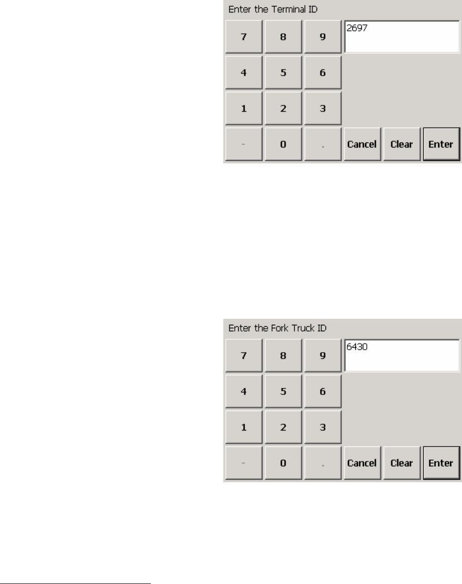
Chapter 4: Scale Setup
Application
2.
Type the Terminal ID in the data field by touching the numeric keys on the keypad.
Touch the Clear button if you wish to clear the data field and start over.
3.
Touch the Enter button to confirm your selection or the Cancel button to cancel any
changes that you made.
Forklift ID
Enter the ID for the forklift on which the scale is installed.
1.
Touch the Forklift ID button to display a keypad on the screen.
2.
Type the Forklift ID in the data field by touching the numeric keys on the keypad.
Touch the Clear button if you wish to clear the data field and start over.
3.
Touch the Enter button to confirm your selection or the Cancel button to cancel any
changes that you made.
Memory The application log lists communication errors and other notable events. The memory
features allow you to define the maximum size of the log and specify the amount of
detail included in each entry. Touch the Memory button to access the features.
(3/05) 4-23
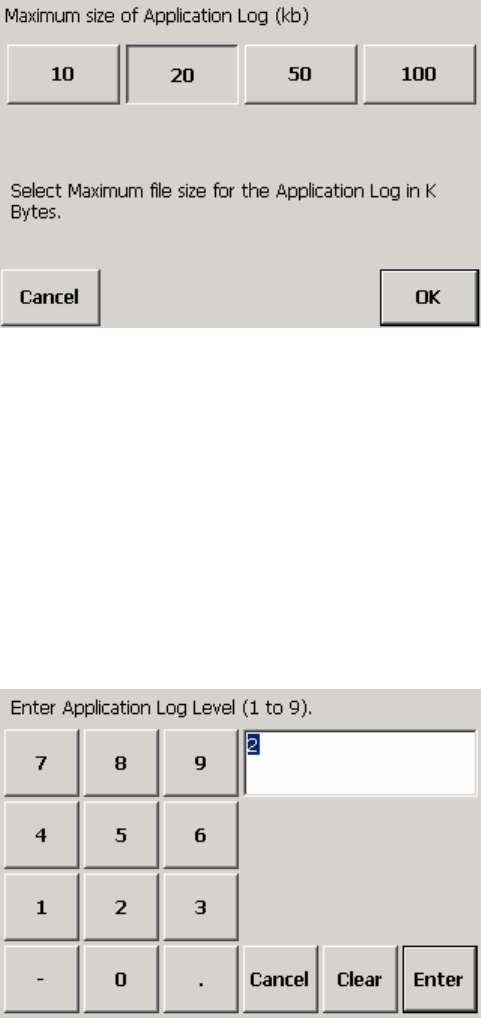
METTLER TOLEDO MCFA Forklift Scale Service Manual
Application Log Size
This feature allows you to specify the maximum amount of data (in kilobytes) that the
log will store. When the log reaches the maximum, it will begin deleting the earliest
entries as new entries are made. The default setting is 20.
1.
Touch the App Log Size button.
2.
Touch a button to select the amount of data to be stored in the log (10, 20, 50, or
100).
3.
Touch the OK button to confirm your selection or the Cancel button to cancel any
changes that you made.
Application Log Level
This feature allows you to specify the amount of detail included in each entry. You can
select a level from 0 to 9, with 9 being the maximum amount of detail. The default is 2.
The level that is specified affects both the application log and communications log.
1.
Touch the App Log Level button to display a keypad on the screen.
2.
Type a number in the data field by touching the numeric keys on the keypad. Touch
the Clear button to clear the data field and start over.
3.
Touch the Enter button to confirm your selection or the Cancel button to cancel any
changes that you made.
(3/05)
4-24

Chapter 4: Scale Setup
Terminal
Reset The Reset button is used to reset the application parameters to the factory default
settings.
1.
Touch the Reset button.
2.
Touch the Reset button to restore the default application parameters or the Cancel
button to keep the current settings.
Terminal
The terminal setup features are used to set date and time, assign passwords, and set
other terminal functions. Touch the Terminal button to display buttons for the individual
terminal setup features.
Date/Time The date/time feature allows you to change the date and time that are displayed on the
controller and to change the formats in which they are displayed. Touch the Date/Time
button to access the features.
Set
Touch the Set button to change the date or time. To center the calendar on the screen,
place your finger on the calendar’s title bar and drag the calendar to a new position.
• To set the month, touch the arrows on either side of the month that is displayed or
touch the month label to choose from a list of months.
• To set the date, touch a date on the calendar.
• To set the time, enter it in the Current Time field. Touch a part of the current time
(hours, minutes, seconds, or AM/PM) and then use the up and down arrows to
make changes.
• To set the time zone, select it from the combo box.
Touch the Apply button or OK button to accept the changes that you have made. Touch
the X button to close the calendar without making changes.
Format
Touch the Format button to change the formats in which the date and time are
displayed. To center the form on the screen, place your finger on the title bar and drag
the form to a new position. There are five tabs on the form: Regional Settings, Number,
Currency, Time, and Date. Touch the Time or Date tab to make changes.
Set the time format:
• To set the time style, select a format from the combo box: (h:mm:ss tt, hh:mm:ss
tt, H:mm:ss, HH:mm:ss). A sample will be displayed on the tab.
• Combo boxes are also available for setting the format of the time separator (:), AM
symbol, and PM symbol.
Set the date format:
• The short date format includes the date, month, and year. The long date format
includes the day of the week, date, month, and year.
(3/05) 4-25
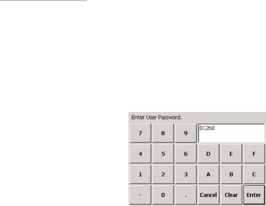
METTLER TOLEDO MCFA Forklift Scale Service Manual
• To set the short date style, select a format from the combo box: M/d/yy; M/d/yyyy;
MM/dd/yy; MM/dd/yyyy; yy/MM/dd; yyyy/MM/dd.
• A combo box is also available for setting the format of the separator (/).
• To set the long date style, select a format from the combo box: dddd, MMMM
dd,yyyy; MMM dd, yyyy; dddd, dd MMMM, yyyy; dd MMMM, yyyy.
Touch the OK button to accept the changes that you have made. Touch the X button to
close the form without making changes.
Passwords You can assign passwords for three security levels: User, Supervisor, and Service. The
default setting is no passwords. If passwords are assigned, you will need to enter a
password when the controller is powered up (or when you try to enter setup or
calibration). If no passwords are assigned, you will have access to all functions without
entering a password. Touch the Passwords button to display the buttons for user,
supervisor, and service passwords.
User
The user password allows access to the scale’s weighing screen functions. If no other
passwords are assigned, it will also allow access to setup functions.
1.
Touch the User button to assign a password for users. A keypad will be displayed
on the screen.
2.
Type an alphanumeric password in the data field by touching the keys on the
keypad. Passwords must be five characters long. Touch the Clear button if you
wish to clear the data field and start over.
3.
Touch the Enter button to confirm the new password or the Cancel button to cancel
any changes that you made.
Supervisor
The supervisor password allows access to the scale’s weighing screen functions and
setup functions. If a service password is assigned, supervisors will not be allowed
access to the scale and communications setup functions.
1.
Touch the Supervisor button to assign a password for supervisors. A keypad will be
displayed on the screen.
(3/05)
4-26

Chapter 4: Scale Setup
Terminal
2.
Type an alphanumeric password in the data field by touching the keys on the
keypad. Passwords must be five characters long. Touch the Clear button if you
wish to clear the data field and start over.
3.
Touch the Enter button to confirm the new password or the Cancel button to cancel
any changes that you made.
Service
The service password allows access to all scale functions.
1.
Touch the Service button to assign a password for service personnel. A keypad will
be displayed on the screen.
2.
Type an alphanumeric password in the data field by touching the keys on the
keypad. Passwords must be five characters long. Touch the Clear button if you
wish to clear the data field and start over.
3.
Touch the Enter button to confirm the new password or the Cancel button to cancel
any changes that you made.
NOTE: Security restrictions depend on which security levels are being used. If no
password is assigned for a security level, the system will function as though that level
does not exist. For example, if there is a user password but no supervisor or service
passwords, then users will have access to setup and calibration functions. The same is
true of access for assigning passwords. If no service password exists, then a supervisor
will be able to assign one. But once a service password has been assigned, a
supervisor will no longer have access to change the service password.
Calibrate Touch This feature allows you to calibrate the touch screen so that the pointer automatically
appears at any location where your finger touches the screen.
1.
Touch the Calibrate Touch button to start the seven-point calibration procedure.
2.
A circular target will appear on the screen. Touch the center of the target. When you
touch it, the target will move to a new location on the screen.
3.
Continue to touch the center of the target each time it moves until all seven points
have been tested.
4.
When the test is completed, the screen will close automatically.
Operating System Touch the OS button to access the operating system features.
Exit to Operating System
This button is used to close the scale application and display the computer desktop on
the scale controller.
1.
Touch the Exit to OS button.
(3/05) 4-27
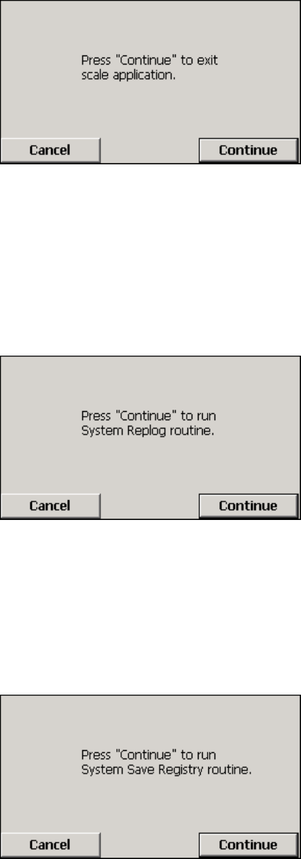
METTLER TOLEDO MCFA Forklift Scale Service Manual
2.
Touch the Continue button to close the scale application or the Cancel button to
return to scale setup.
Launch Replog
This button is used to set up communication between the controller and a personal
computer. You will need to use a cable to connect the controller to the computer.
1.
Touch the Launch replog button.
2.
Touch the Continue button to launch the replog or the Cancel button to return to
scale setup without launching the replog.
Save Registry
This button is used to save the Windows CE configuration.
1.
Touch the Save Registry button.
2.
Touch the Continue button to save the registry or the Cancel button to return to
scale setup without saving the registry.
(3/05)
4-28
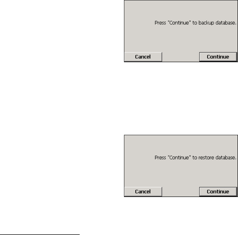
Chapter 4: Scale Setup
Terminal
Backup Database
This button is used to create a backup file containing the metrological setup data for the
scale.
1.
Touch the Backup Database button.
2.
Touch the Continue button to back up the database or the Cancel button to return
to scale setup without backing up the database.
Restore Database
This button allows you to replace the scale’s metrological setup data with the data
stored in a backup file.
1.
Touch the Restore Database button.
2.
Touch the Continue button to restore the database or the Cancel button to return to
scale setup without restoring the database.
Brand Setup This feature is used to identify the brand of forklift truck on which the scale is installed.
1.
Touch the Brand Setup button.
(3/05) 4-29
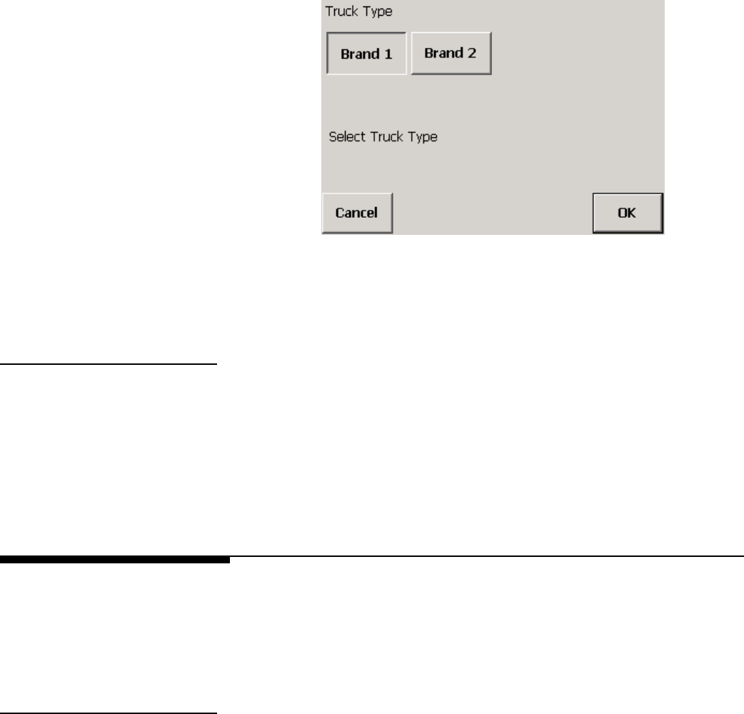
METTLER TOLEDO MCFA Forklift Scale Service Manual
2.
Select the brand by touching the Brand 1 or Brand 2 button.
3.
Touch the OK button to confirm your selection or the Cancel button to cancel any
changes that you made.
Reset The Reset button is used to reset the terminal parameters to the factory default settings.
1.
Touch the Reset button.
2.
Touch the Reset button to restore the default terminal parameters or the Cancel
button to keep the current settings.
NOTE: Using the Reset button will delete any passwords that you assigned.
Communications
The communications setup features are used to configure communications between the
scale controller and carriage, as well as communications with other devices. Touch the
Communications button to display buttons for the individual communications setup
features.
Scale Radio You can configure communications between the scale carriage radio and controller
radio. Touch the Scale Radio button to access the scale radio setup features.
Carriage ID
Enter an ID for the carriage radio. The default Carriage ID is 000001.
1.
Touch the Carriage ID button to display a keypad on the screen.
(3/05)
4-30
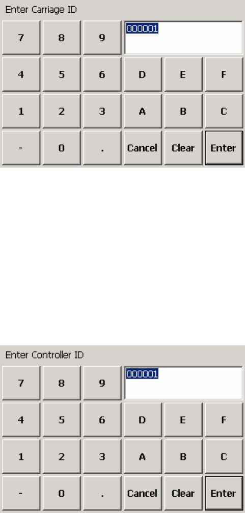
Chapter 4: Scale Setup
Communications
2.
Type an alphanumeric ID in the data field by touching the keys on the keypad.
Touch the Clear button if you wish to clear the data field and start over.
3.
Touch the Enter button to confirm your selection or the Cancel button to cancel any
changes that you made.
You must restart the scale controller to activate a new selection.
Controller ID
Enter an ID for the controller radio. The default Controller ID is 000001.
1.
Touch the Controller ID button to display a keypad on the screen.
2.
Type an alphanumeric ID in the data field by touching the keys on the keypad.
Touch the Clear button if you wish to clear the data field and start over.
3.
Touch the Enter button to confirm your selection or the Cancel button to cancel any
changes that you made.
You must restart the scale controller to activate a new selection.
Radio Channel
This feature allows you to select the channel used for radio communication between the
controller and carriage. The default channel is 65. If you are using more than one forklift
scale at your facility, select a different channel for each scale.
1.
Touch the Radio Channel button to display a keypad on the screen.
(3/05) 4-31
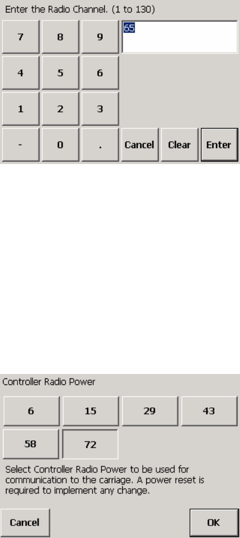
METTLER TOLEDO MCFA Forklift Scale Service Manual
2.
Type a number in the data field by touching the numeric keys on the keypad. Valid
selections are 1 to 130. Touch the Clear button if you wish to clear the data field
and start over.
3.
Touch the Enter button to confirm your selection or the Cancel button to cancel any
changes that you made.
You must restart the scale controller to activate a new selection.
Controller Power
This feature allows you to select the power level for the controller radio. A high power
level is recommended if the radio transmission experiences interference. The default
setting is 72.
1.
Touch the Controller Power button.
2.
Touch the button for the desired power level (6, 15, 29, 43, 58, or 72). The
numbers are approximate percentages of the maximum power.
3.
Touch the OK button to confirm your selection or the Cancel button to cancel any
changes that you made.
You must restart the scale controller to activate a new selection.
(3/05)
4-32
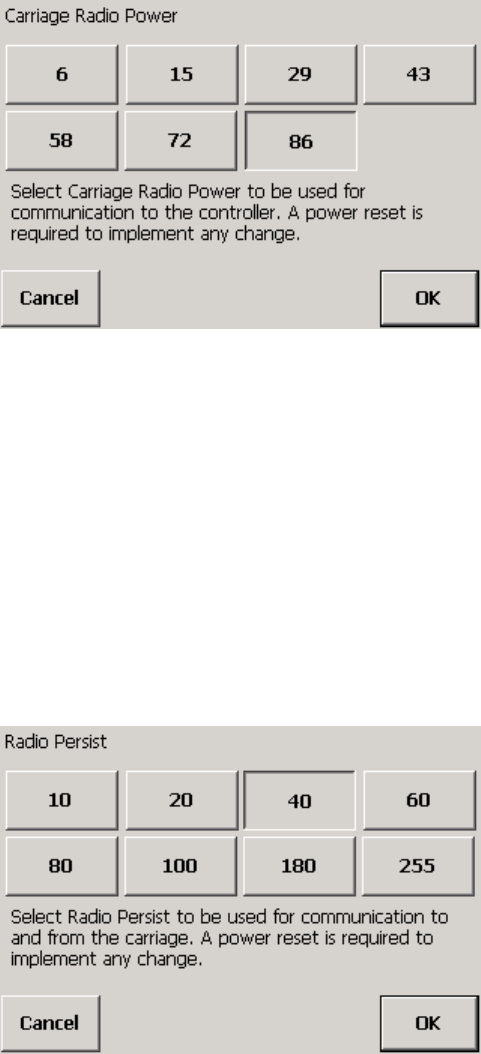
Chapter 4: Scale Setup
Communications
Carriage Power
This feature allows you to select the power level for the carriage radio. A high power
level is recommended if the radio transmission experiences interference. The default
setting is 86.
1.
Touch the Carriage Power button.
2.
Touch the button for the desired power level (6, 15, 29, 43, 58, 72, 86, or 100).
The numbers are approximate percentages of the maximum power.
3.
Touch the OK button to confirm your selection or the Cancel button to cancel any
changes that you made.
You must restart the scale controller to activate a new selection.
Radio Persist
This feature allows you to select the fall-back time for the controller and carriage radios.
If communication is disrupted, the system will pause (fall back) before continuing to
transmit a signal. The default setting is 40.
1.
Touch the Radio Persist button.
2.
Touch the button for the desired fall-back time (10, 20, 40, 60, 80, 100, 180, or
255).
(3/05) 4-33
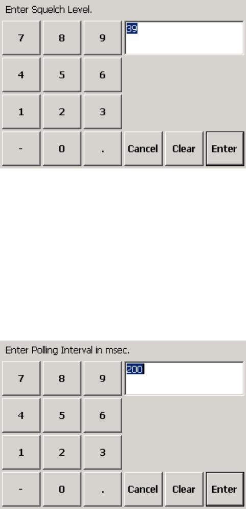
METTLER TOLEDO MCFA Forklift Scale Service Manual
3.
Touch the OK button to confirm your selection or the Cancel button to cancel any
changes that you made.
You must restart the scale controller to activate a new selection.
Squelch
The squelch feature is used to suppress background noise generated by the scale
controller. A higher setting provides more noise suppression. The default setting is 39.
1.
Touch the Squelch button to display a keypad on the screen.
2.
Type a squelch level in the data field by touching the numeric keys on the keypad.
Touch the Clear button if you wish to clear the data field and start over.
3.
Touch the Enter button to confirm your selection or the Cancel button to cancel any
changes that you made.
Polling Interval
The polling interval is the time delay (in milliseconds) between a request for data and
the scale’s response. The default setting is 200 for radios operating at 5 Hz.
1.
Touch the Polling Interval button to display a keypad on the screen.
2.
Type a polling interval in the data field by touching the numeric keys on the keypad.
Touch the Clear button if you wish to clear the data field and start over.
(3/05)
4-34
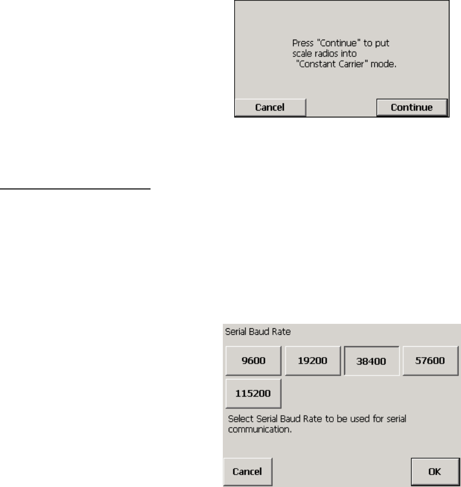
Chapter 4: Scale Setup
Communications
3.
Touch the Enter button to confirm your selection or the Cancel button to cancel any
changes that you made.
Carrier On
This feature sets the controller and carriage radios so that they can broadcast in
constant carrier mode. It is a diagnostics tool that allows you to use a frequency meter
to check the broadcast frequency of the radios. To check the frequency of one radio, you
will need to shut off power to the other radio. In order to return the radios to normal
operating mode, you must restart them.
1.
Touch the Carrier On button.
2.
Touch the Continue button to set the radios to constant carrier mode or the Cancel
button to return to scale setup without changing the radio mode.
COM1 A serial communication port (COM1) is available so that the scale controller can be
connected to printers and other serial devices. Touch the COM1 button to view or
change the serial communication settings.
Baud Rate
Specify the baud rate for serial communications. The default setting is 38400.
1.
Touch the Baud Rate button.
(3/05) 4-35
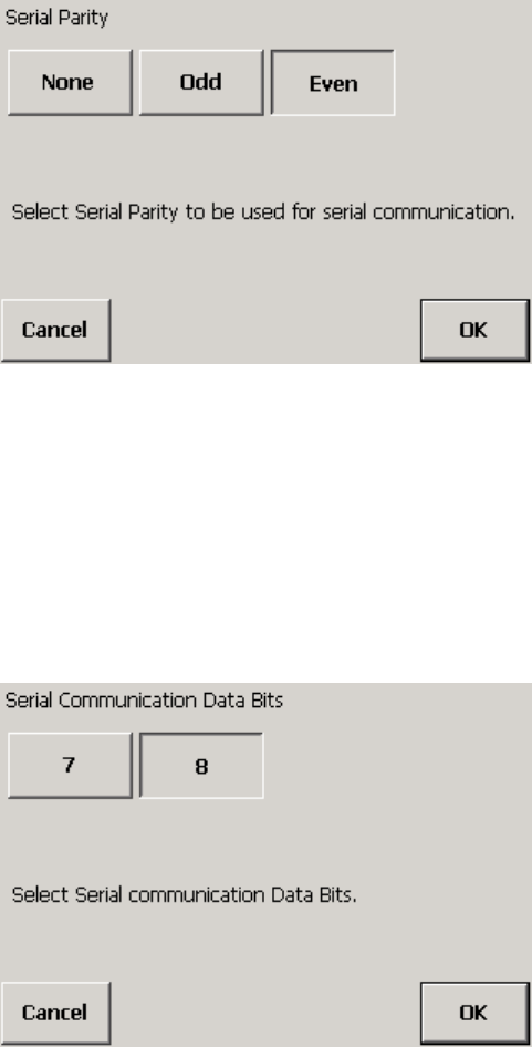
METTLER TOLEDO MCFA Forklift Scale Service Manual
2.
Touch the button for the desired baud rate setting (9600, 19200, 38400, 57600,
or 115200).
3.
Touch the OK button to confirm your selection or the Cancel button to cancel any
changes that you made.
Parity
Specify the parity for serial communications. The default setting is Even.
1.
Touch the Parity button.
2.
Touch the button for the desired parity setting (None, Odd, or Even).
3.
Touch the OK button to confirm your selection or the Cancel button to cancel any
changes that you made.
Data Bits
Specify the number of data bits for serial communications. The default setting is 8.
1.
Touch the Data Bits button.
2.
Touch the button for the desired data bit setting (7 or 8).
3.
Touch the OK button to confirm your selection or the Cancel button to cancel any
changes that you made.
(3/05)
4-36
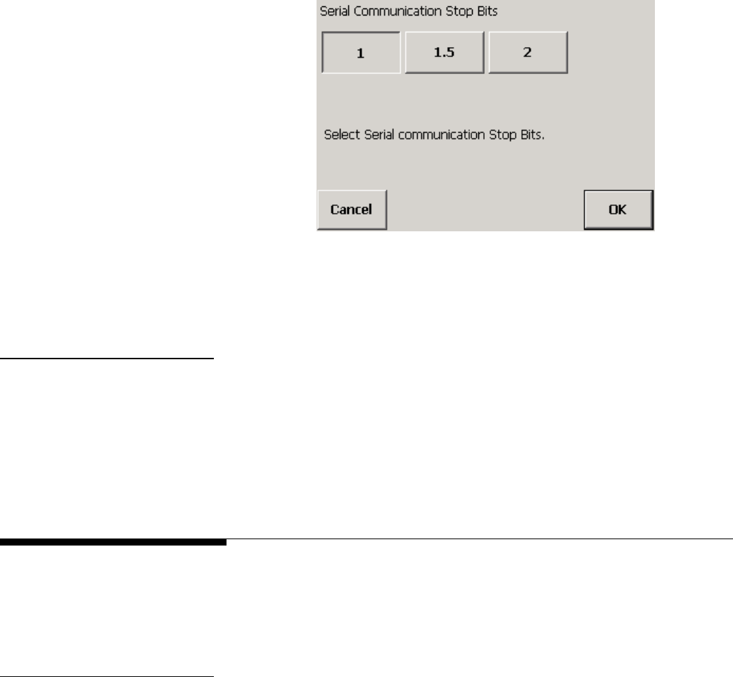
Chapter 4: Scale Setup
Maintenance
Stop Bits
Specify the number of stop bits for serial communications. The default setting is 1.
1.
Touch the Stop Bits button.
2.
Touch the button for the desired stop bit setting (1, 1.5, or 2).
3.
Touch the OK button to confirm your selection or the Cancel button to cancel any
changes that you made.
Reset The Reset button is used to reset the communications parameters to the factory default
settings.
1.
Touch the Reset button.
2.
Touch the Reset button to restore the default communications parameters or the
Cancel button to keep the current settings.
Maintenance
The maintenance setup features are used to monitor and test the scale’s operations.
Touch the Maintenance button to display buttons for the individual maintenance setup
features.
Log The application log keeps a list of communication errors and other notable events. You
can view the log or delete entries from the log. Touch the Log button to access the
features.
View Application Log
This button opens the application log so that you can view the log entries.
1.
Touch the View App Log button.
(3/05) 4-37
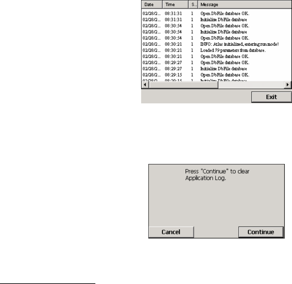
METTLER TOLEDO MCFA Forklift Scale Service Manual
2.
Touch the Exit button to close the log.
Clear App Log
1.
Touch the Clear App Log button.
2.
Touch the Continue button to delete all existing log entries or the Cancel button to
keep the current entries.
Diagnostics The diagnostics features are used to check system operations. Touch the Diagnostics
button to access the features.
Memory
Touch the Memory button to test the compact flash memory. Touch the Start button to
perform the test.
Display Resolution
Touch the Display Resolution button to test the screen’s resolution at four settings.
When all four resolutions have been displayed, touch the OK button to complete the test.
(3/05)
4-38
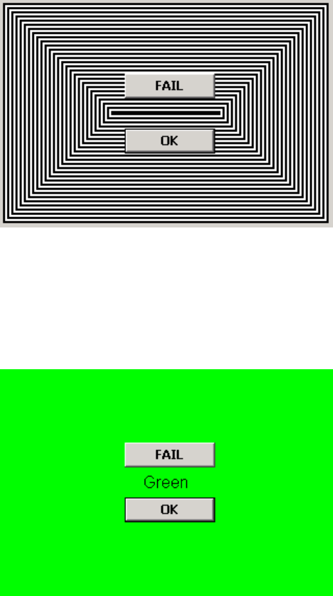
Chapter 4: Scale Setup
Maintenance
Display Color
Touch the Display Color button to test the screen’s colors: black, red, green, blue, and
white. When all five colors have been displayed, touch the OK button to complete the
test.
Streaming Data
The streaming data log keeps track of the data transmitted between the controller and
carriage radios. The amount of data recorded depends on the application log level (see
application setup).
1.
Touch the Streaming Data button to open the log.
(3/05) 4-39
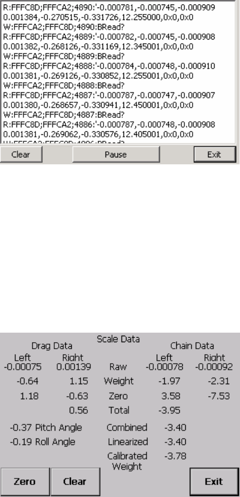
METTLER TOLEDO MCFA Forklift Scale Service Manual
2.
Touch the Pause button to stop the system from displaying new entries so that you
can read the log.
3.
After viewing the log, touch the Clear button to delete all log entries or the Exit
button to close the log.
Data Screen
The data screen displays data that is used to check the condition of the load cells. It
also displays the pitch and roll angles for the mast.
1.
Touch the Data Screen button.
2.
Touch the Zero button to establish the existing zero setting as a reference point.
Touch the Clear button if you wish to clear the zero reference.
3.
Touch the Exit button to return to the setup menu.
Communications Timing
This screen displays the system’s communications timing data (in milliseconds). The
system averages data from a series of communications. You can reset the data so that
the system starts averaging from the current transmission.
1.
Touch the Comms Timing button.
(3/05)
4-40
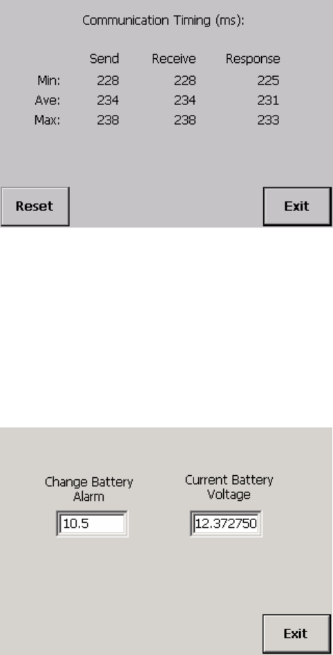
Chapter 4: Scale Setup
Maintenance
2.
Touch the Reset button to start averaging a new series of data.
3.
Touch the Exit button to close the screen.
Battery Voltage
This screen displays the current battery voltage level and the setting for the alarm used
to signal that the battery needs to be changed.
1.
Touch the Battery Voltage button to view the battery settings.
2.
Touch the Exit button to return to the setup menu.
Radio Power
This screen displays the current receive and transmit power for the controller and
carriage radios. The radio power level is set in communications setup.
1.
Touch the Radio Power button.
(3/05) 4-41
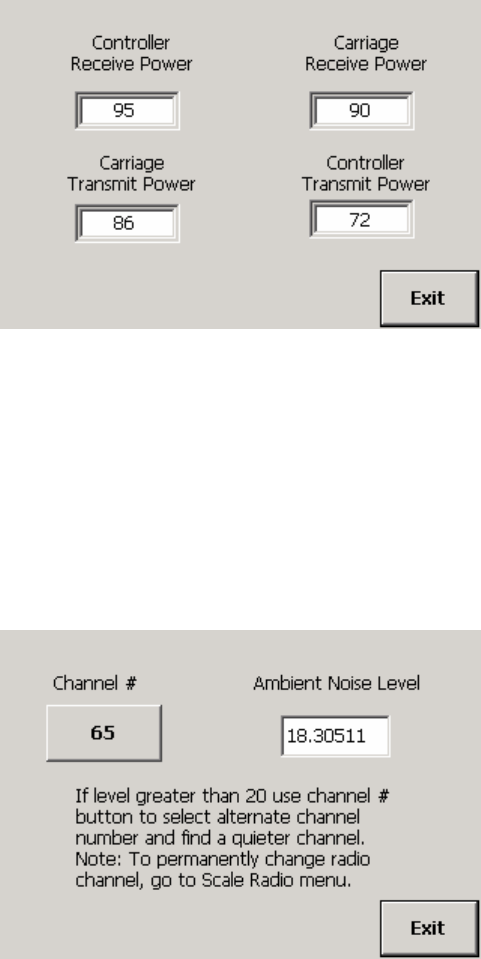
METTLER TOLEDO MCFA Forklift Scale Service Manual
2.
Touch the Exit button to return to the setup menu.
Ambient Noise
This screen is used to check the ambient noise level for the radio channels. Lower
ambient noise levels provide better communication. For a forklift scale, you should
select a radio channel with a noise level of 20 or lower.
1.
Touch the Ambient Noise button. The noise level will be shown for the radio
channel that is currently being used.
2.
To view the noise level for another channel, touch the Channel # button. A keypad
will be displayed on the screen.
3.
Type in a number by touching the numeric keys on the keypad. Touch the Clear
button if you wish to clear the data field and start over
4.
Touch the Enter button to confirm your selection.
5.
You can now view the ambient noise level for the new channel. Touch the Exit
button to close the screen.
This feature is used to check the ambient noise levels on radio channels. To change the
channel used for radio communication, go to the Radio Channel button in
communications setup.
(3/05)
4-42
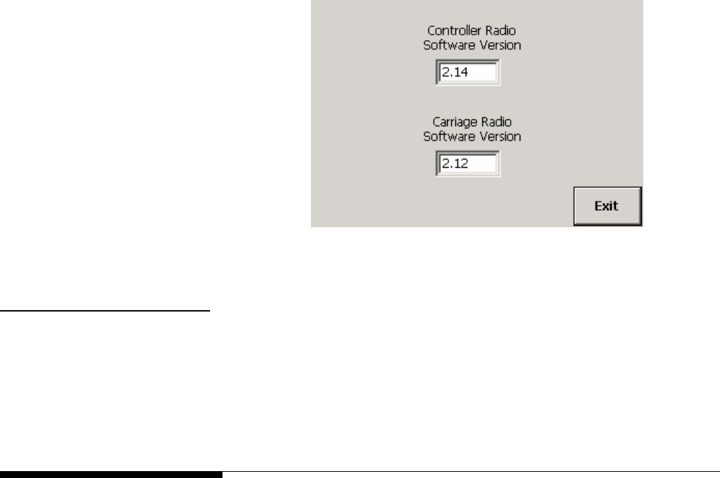
Chapter 4: Scale Setup
Exit Setup
Radio Version
This screen displays the radio firmware version for the controller and carriage radios.
1.
Touch the Radio Version button to view the version numbers.
2.
Touch the Exit button to close the screen.
Reset The Reset button is used to reset all setup parameters to the factory default settings.
1.
Touch the Reset button.
2.
Touch the Reset button to restore the default parameters or the Cancel button to
keep the current settings.
Exit Setup
The Exit Setup button is used to exit setup mode and return to the scale’s main
weighing screen. You will be prompted to confirm any setup changes before exiting.
1.
Touch the Exit Setup button.
2.
Touch the Save button to save any configuration changes, or touch the Cancel
button to cancel the changes and return to the previous settings.
3.
The controller will return to the main weighing screen.
(3/05) 4-43
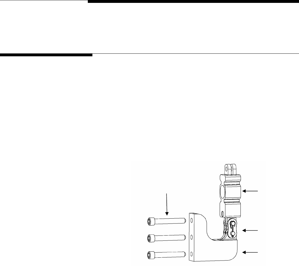
Chapter 5: Routine Care and Maintenance
General
5
Routine Care and Maintenance
General
Once you have installed your scale, you should have an authorized METTLER TOLEDO
representative periodically inspect and calibrate it. If the scale is used for legal-for-trade
purposes, consult the local weights and measures authorities for minimum inspection
requirements. Contact your local authorized METTLER TOLEDO service representative for
information about periodic inspection and calibration services.
IMPORTANT: As part of the regular maintenance schedule, check the bolts that secure
the two chain load cell mounts to the carriage. Check the torque of the bolts after the first
100 hours that the forklift scale has been in use, and check it every 1,000 hours
thereafter. The bolts on the simplex version should be torqued to 50 ft-lb (see Figure 5-
1). The bolts on the triplex version should be torqued to 180 ft-lb (see Figure 5-2).
Torque Bolts to 50 ft-lb Chain Load Cell
Master Link
Chain Mount
Figure 5-1: Chain Mount Assembly (Simplex Version)
(3/05) 5-1
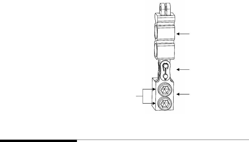
METTLER TOLEDO MCFA Forklift Scale Service Manual
Chain Load Cell
Master Link
Chain Mount
Torque Bolts to 180 ft-lb
Figure 5-2: Chain Mount Assembly (Triplex Version)
Cleaning
Clean the scale controller’s cover with a soft, clean cloth that has been dampened with
a mild window-type cleaner or detergent. DO NOT USE ANY TYPE OF INDUSTRIAL
SOLVENT OR CHEMICALS. DO NOT SPRAY CLEANER DIRECTLY ONTO THE UNIT. DO
NOT HOSE DOWN.
(3/05)
5-2
Chapter 6: Troubleshooting
General
6
Troubleshooting
General
If a scale is not working properly, find out as much about the problem as possible. Try
to determine whether the problem is constant or intermittent. Mechanical and electrical
influences can cause malfunctions, so be patient and use sound logic when
troubleshooting.
WARNING
PERMIT ONLY QUALIFIED PERSONNEL TO SERVICE THIS
EQUIPMENT. EXERCISE CARE WHEN MAKING CHECKS,
TESTS, AND ADJUSTMENTS THAT MUST BE MADE WITH
POWER ON. FAILING TO OBSERVE THESE PRECAUTIONS
CAN RESULT IN BODILY HARM.
DANGER
IF USED IN A HAZARDOUS AREA, THE HAZARDOUS AREA
MUST BE MADE SAFE PRIOR TO INSTALLATION,
REPLACEMENT, OR TROUBLESHOOTING. FAILURE TO
COMPLY COULD RESULT IN PERSONAL INJURY, DEATH,
AND/OR PROPERTY DAMAGE.
WARNING
BEFORE CONNECTING/DISCONNECTING ANY INTERNAL ELECTRONIC COMPONENTS
OR INTERCONNECTING WIRING BETWEEN ELECTRONIC EQUIPMENT, ALWAYS
REMOVE POWER AND WAIT AT LEAST 30 SECONDS. FAILURE TO OBSERVE THESE
PRECAUTIONS COULD RESULT IN BODILY HARM OR DAMAGE TO OR DESTRUCTION
OF THE EQUIPMENT.
(3/05) 6-1

METTLER TOLEDO MCFA Forklift Scale Service Manual
Error Messages
The following messages are displayed in the message bar on the controller’s main
weighing screen.
Message Remedy
ERR: Load is not stable – cannot take tare! Wait for scale to stabilize and then capture tare weight.
ERR: Cannot take a negative tare! Remove load from scale and zero scale.
ERR: Invalid mode – must be in Gross mode! Switch scale to gross weighing mode.
ERR: Load is not stable – cannot take zero! Wait for scale to stabilize and then capture zero.
ERR: Invalid mode – clear Tare to rezero! Clear the tare weight and then capture zero.
ERR: Current weight %6.0f, > manual zero range! Remove load from scale.
INFO: Configuration changes saved! Message appears when you exit setup and save changes.
INFO: Configuration changes abandoned! Message appears when you exit setup without saving changes.
ERR: Access to Setup not authenticated! Check the password and enter it again.
ERR: No Tare, ‘Net’ Invalid Mode Capture a tare weight before switching to net weighing mode.
ERR: Load is not stable – cannot accumulate! Wait for scale to stabilize and then accumulate.
ERR: AZM weight %6.0f, > manual zero range! Remove load from scale.
SEND Radio Comm PID ERROR System will resend data automatically.
READ Radio Comm PID ERROR System will reread data automatically.
(3/05)
6-2

Chapter 6: Troubleshooting
Error Messages
The following messages are displayed in pop-up windows on the scale controller.
Message Remedy
Radio controller not communicating. Check carriage battery. Make sure radio channel selected in
setup matches channel indicated by blinking light in telemetry
box.
WARN: Controller Radio ID does not match database. Do you
want to update the database Controller ID?
Update Controller ID.
WARN: Controller Radio Power does not match database. Do
you want to update controller power?
Update controller power.
WARN: Controller Radio Persist does not match database. Do
you want to update controller persist?
Update controller persist.
WARN: Carriage Radio Power does not match database. Do you
want to update carriage power?
Update carriage power.
WARN: Carriage Radio Persist does not match database. Do
you want to update carriage persist?
Update carriage persist.
Carriage Calibration Constants do not match database.
Updating the database will take about 30 seconds. Do you
want to update the database?
Update database.
Failed to load Calibration Constants from Carriage Radio Recycle power to scale controller.
No Scale Available Check carriage battery. Make sure radio channel selected in
setup matches channel indicated by blinking light in telemetry
box.
WARN: Radio controller parameters do not match database.
Controller Channel = %i. Database Channel = %i. Do you want
to update the Controller Channel and Carriage Channel with the
database values?
Update controller channel and carriage channel.
WARN: Radio controller parameters do not match database.
Controller Channel = %i. Database Channel = %i. Do you want
to update the Controller Channel with the database values?
Update controller channel.
Carriage Scale is not communicating. Check carriage battery. Make sure radio channel selected in
setup matches channel indicated by blinking light in telemetry
box.
WARN: Carriage Radio ID does not match database. Carriage
Radio ID = %i. Database ID = %i. Do you want to update the
database?
Update database.
Force Calibration Constants to Carriage Radio: Updating
Constants to the Carriage may take 30 seconds. Reset Scale
when Complete.
Update constants. Then recycle power to scale controller.
Initialize Carriage parameters failed. Try to initialize carriage parameters again.
Data is unstable. Wait for scale to stabilize before each calibration step.
Battery Voltage Low. Replace Battery. Replace battery in scale carriage.
(3/05) 6-3

METTLER TOLEDO MCFA Forklift Scale Service Manual
Scale Controller
Make sure that the scale controller is receiving power and is communicating with the
scale carriage.
• The controller is powered by the forklift truck’s battery. When the forklift truck’s
motor is shut off, the controller will continue to operate until an internal time delay
cuts off power. With the forklift truck’s motor running, power up the controller by
pressing the on/off button on the front cover. If the controller does not start, check
the wiring that connects the controller to the battery to make sure that it is not
damaged or loose.
• The controller communicates with the scale carriage by radio transmission. If there
is a communication problem, the message “No Scale Communication” will be
displayed on the controller’s main weighing screen. Check the scale carriage
battery to make sure that it is charged and that it is inserted into the battery
compartment correctly. The battery compartment is wired to the printed circuit board
(PCB) inside the telemetry enclosure. Make sure that the battery wire is not loose or
damaged.
• If the scale carriage is sending a signal, the channel indicator on the telemetry box
will be flashing. The flashing red light indicates which radio channel is being used.
The sequence starts with five quick flashes, followed by a pause. Then there is a
series of slower flashes for each numeral, with a pause between numerals. For
example, five quick flashes, a pause, six slower flashes, a pause, and then 5
slower flashes indicates channel 65 (the default channel). Zero is indicated by ten
flashes. Since you can use radio channels 1 to 130, a channel can consist of as
few as one numeral or as many as three numerals.
Check Mechanical
Components
Check the scale to make sure the mechanical components are not damaged, worn, or
binding.
• Check the scale’s flexures to make sure they are not bent or warped.
• Make sure that no scale components are loose. All bolts should be tightened
securely.
• Make sure that the scale carriage moves freely when it is raised and lowered.
• Make sure that that scale is not binding. The only scale components that should be
touching the mast are the rollers.
(3/05)
6-4
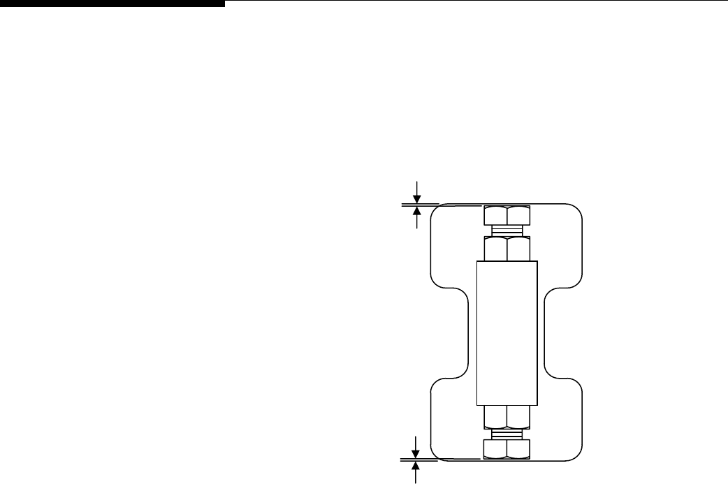
Chapter 6: Troubleshooting
Check Overload Gaps
Check Overload Gaps
The overload bumpers are designed to protect the load cells and flexures from being
damaged if an excessive load is placed on the scale. Use a feeler gauge to check the
overload bumper gaps. All gaps should be set to 0.020 inch ±0.005 inch (see Figure
6-1).
0.020 inch
0.020 inch
Figure 6-1: Overload Bumper Gaps
(3/05) 6-5
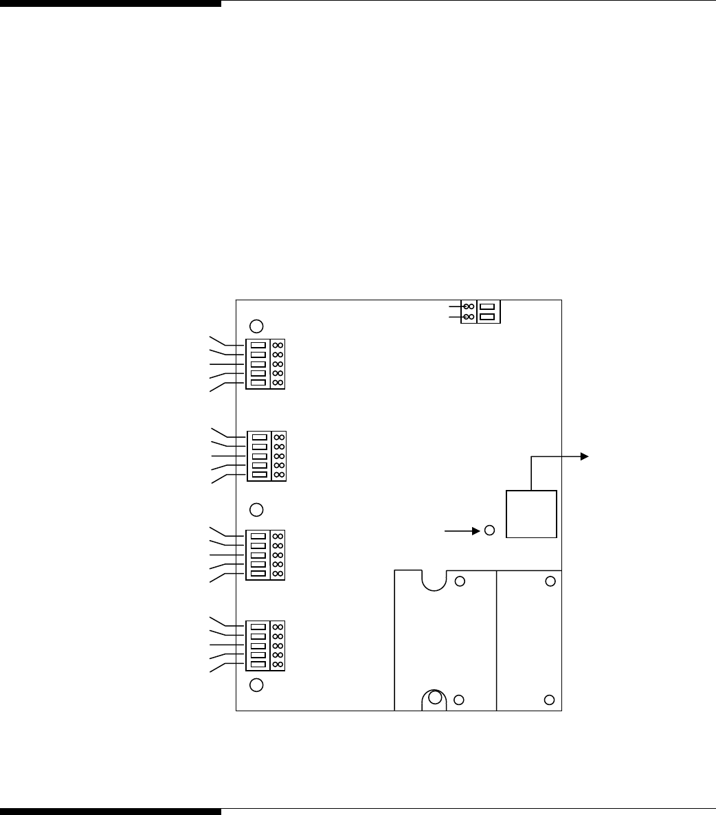
METTLER TOLEDO MCFA Forklift Scale Service Manual
Check Wiring 1.
Remove power from the system.
2.
Remove the cover from the telemetry enclosure and check the interior for moisture
or foreign material.
3.
Make sure that all wiring connections are tight and that no insulation material is
touching the terminal contacts.
4.
Check all load cell connections to make sure they are wired correctly. The wiring
color codes are shown in Figure 6-2.
5.
Check the cable connections and cord grips. If the cord grips are loose, tighten the
nuts on the cord-grip clamp bar. Use a nut driver to tighten the nuts. Be careful to
tighten the nuts only to the point at which the cables will not slide through the cord
grips. Do not overtighten the nuts.
(Black) -
(Red) +
To Battery
(Green) +EXE
(Black) –EXE
(Yellow) Shield
(White) +IN
(
Red
)
-IN
To Left Chain
Load Cell
(Green) +EXE
(Black) –EXE
(Yellow) Shield
(White) +IN
(
Red
)
-IN
To Left Drag
Load Cell
(Green) +EXE
(Black) –EXE
(Yellow) Shield
(White) +IN
(
Red
)
-IN
To Right
Chain Load
To Right Drag
Load Cell
(Green) +EXE
(Black) –EXE
(Yellow) Shield
(White) +IN
(
Red
)
-IN
To Inclinometer
Radio Channel
Indicato
r
Figure 6-2: Load Cell Wiring Codes
Check Force Data
The force data being communicated to the scale controller provides a good indication of
how the load cells are performing.
1.
Power up the scale controller.
(3/05)
6-6

Chapter 6: Troubleshooting
Check Load Cells
2.
Touch the Setup button to enter setup mode.
3.
Open the data screen by touching the Maintenance button, the Diagnostics button,
and the Data Screen button.
4.
Compare the force readings for the left drag load cell and the right drag load cell.
5.
Compare the force readings for the left chain load cell and the right chain load cell.
If the force data is out of tolerance, check the load cells to make sure they are working
properly. The “Weight” reading for each drag load cell should be approximately -60 lb
(±40 lb). The “Weight” readings for the chain load cells should be approximately equal
(±100 lb). The “Total” readings for the drag load cells and chain load cells should be
opposite and approximately equal. For example, if the drag load cell total is -300, the
chain load cell total should be approximately +300. The calibrated weight is the sum of
those two numbers and should be approximately zero.
Check Load Cells 1.
Remove power from the system. Fully disconnect each load cell and check for
proper input/output resistances (see Table 6-1).
Measuring Points Resistance
+Exc (Green) to -Exc (Black) Greater than 1,000 ohms (typically 1,160 ohms)
+Sig (White) to -Sig (Red) 1,000 ±5 ohms
Table 6-1: Load Cell Measuring Points
2.
If resistance is within specification, perform a shorted-signal symmetry test.
•
Short the signal leads together and place one multimeter lead on the shorted
signals and one lead on the +Excitation wire. Note the resistance value.
•
Remove the lead from the +Excitation wire and place it on the –Excitation wire.
The two resistance values should be approximately equal.
3.
If the load cells pass the shorted-signal test, reconnect them and reapply power to
the scale. Confirm that the proper excitation voltage is reaching the load cells by
placing multimeter leads on the excitation positions of each load cell terminal.
4.
If proper excitation voltage is reaching the load cells, check the output signal from
each cell by disconnecting the signal leads and measuring voltage output. If one
cell has a particularly high or low dead-load output, it is suspect. The maximum
output possible from any cell is 30 mV at 15 VDC excitation and loaded to gross
capacity.
5.
If any load cell has an unusual signal, remove all load from that cell.
•
With the power on, measure the output from the suspect load cell. The no-load
zero output should be ±1.5% of the full scale output. For example, if the
excitation voltage is 15 VDC, then the full scale output would be 30 mV and
the no-load zero output should be within ±0.45 mV.
6.
If a load cell fails any of the above tests, replace it.
(3/05) 6-7
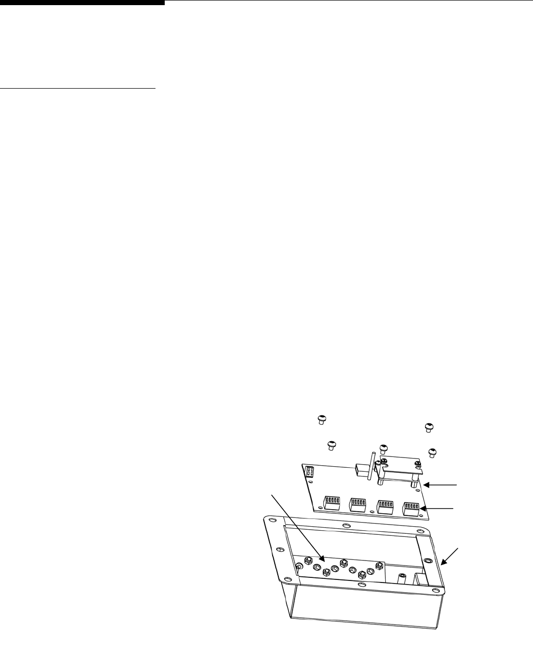
METTLER TOLEDO MCFA Forklift Scale Service Manual
Load Cell Replacement
If tests indicate that a load cell is not working properly, remove the load cell and replace
it with a new one.
Removing a Chain Load
Cell (Simplex)
1.
Raise the carriage to a height that will make it easy to reach the load cells and
other scale components.
2.
Shut off the forklift truck’s motor.
3.
Remove the battery by pressing the tab toward the center of the battery and pulling
the battery from the battery compartment.
4.
Remove the cover to the scale’s telemetry enclosure. The cover is held in place by
seven flat head cap screws. Leave the socket head screw in place. It attaches the
enclosure to the carriage.
5.
The load cell cables are wired to the four terminal strips on the printed circuit board
(PCB) inside the telemetry enclosure. Locate the cable for the load cell that you are
replacing. You should be able to identify it by the tag attached to the cable.
Disconnect the cable’s wires from the terminal strip by inserting the tip of a flat-
blade screwdriver into the slot next to each wire and removing the wire from the
terminal.
6.
Remove the five Phillips head screws that attach the PCB to the enclosure. Move
the PCB out of the way so that you have access to the cord-grip clamp bar (see
Figure 6-3). In order to remove the PCB, you might need to disconnect the battery
wires and unplug the inclinometer.
Terminal Strips
Cord-Grip Clamp Bar PCB
Telemetry Enclosure
Figure 6-3: Telemetry Enclosure
(3/05)
6-8
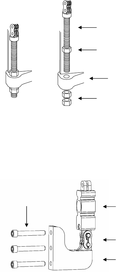
Chapter 6: Troubleshooting
Load Cell Replacement
7.
Loosen the six nuts on the cord-grip clamp bar. This will loosen the cord grips so
that you can remove the cable.
8.
Remove the socket head screw that secures the telemetry enclosure to the carriage.
9.
Pull the load cell cable through the cord grip to remove it from the telemetry
enclosure.
10.
The load cell cables are routed through the scale carriage under the cover plates
located at the top and bottom of the carriage. Remove the cover plate that conceals
the cable for the load cell you are replacing.
11.
Disconnect the chain anchor from the mast by removing the lower nut from the
threaded anchor (see Figure 6-4).
Jam Nut
Mast
Jam Nuts
Chain Anchor
Figure 6-4: Chain Anchor Assembly
12.
Pull the chain up and over the pulley.
13.
Remove the three bolts that secure the chain mount to the carriage. Then remove
the entire assembly (chain mount, load cell, and chain) from the carriage (see
Figure 6-5).
Bolts Chain Load Cell
Master Link
Chain Mount
Figure 6-5: Chain Mount Assembly
(3/05) 6-9
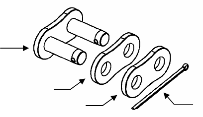
METTLER TOLEDO MCFA Forklift Scale Service Manual
14.
Remove the cotter pin from the master link that secures the load cell to the chain
mount (See Figure 6-6). Take apart the master link, using a C-clamp or similar
device to press the master link through the link plates. Do not use a hammer or
other tool to strike the master link. It could damage the link.
Master Link
Link Plate (Large Holes)
Cotter Pin
Link Plate (Small Holes)
Figure 6-6: Master Link Assembly
15.
Remove the cotter pin and master link that secure the load cell to the chain.
(3/05)
6-10

Chapter 6: Troubleshooting
Load Cell Replacement
Installing a New Chain
Load Cell (Simplex)
1.
Use a master link to connect the new load cell to the chain. The chain should be
connected to the top of the load cell (the end opposite the load cell cable).
Assemble the master link as shown in Figure 6-6. Using a C-clamp or similar
device, press the master link assembly together just enough so that you can insert
the cotter pin in the holes. If the link is too tight, it can bind against the load cell
and chain.
2.
Use a master link to connect the other end of the load cell to the chain mount.
Make sure that the load cell cable is facing away from the three bolt holes in the
chain mount. Assemble the master link as shown in Figure 6-6. Using a C-clamp
or similar device, press the master link assembly together just enough so that you
can insert the cotter pin in the holes. If the link is too tight, it can bind against the
load cell and chain mount.
3.
Bolt the chain mount to the carriage, using the three bolts that were removed earlier
(see Figure 6-5). Torque all three bolts to 60 ft-lb (or 120% of the prescribed
torque value). Loosen all three bolts so that all torque is relieved. Retighten all bolts
to the prescribed torque of 50 ft-lb. The application of a medium-grade thread
locker is acceptable.
4.
Route the chain up and over the pulley.
5.
Remove the lower nut from the threaded chain anchor. Insert the threaded chain
anchor into the mounting hole in the mast. Place the lower nut on the threaded
anchor and tighten it until both it and the upper nut are tight against the mast (see
Figure 6-4).
6.
If the load cell is on the opposite side of the carriage from the telemetry enclosure,
route the load cell cable through the scale carriage under the cover plate that you
removed.
7.
Insert the load cell cable through the cord grip into the telemetry enclosure.
8.
Wire the load cell cable to the terminal strip on the printed circuit board (PCB) inside
the telemetry enclosure. Connect the wires according to the wiring codes in Figure 6-
2. To connect a wire, insert the tip of a flat-blade screwdriver into the appropriate
slot in the terminal and insert the wire into the opening across from the slot.
9.
Tighten the six nuts on the cord-grip clamp bar (see Figure 6-3). Use a nut driver
to tighten the nuts. Be careful to tighten the nuts only to the point at which the
cables will not slide through the cord grips. Do not overtighten the nuts.
10.
Use the socket head screw to secure the telemetry enclosure to the carriage.
11.
Replace the PCB in the enclosure and secure it with the five Phillips head screws. If
you disconnected the battery wire and inclinometer from the PCB, reconnect them.
12.
Coil any excess cable and store it in the open area of the carriage where the cover plate
was removed. Replace the cover plate and secure it with six Phillips head screws.
13.
Replace the cover on the telemetry enclosure and secure it with seven flat head
screws.
14.
Insert the battery in the battery compartment.
15.
Power up the scale controller and enter its setup mode. Open the data screen and
check the output for the two chain load cells. The output should be approximately
equal (±100 lb). Adjust the tension on the chain connected to the new load cell
until the outputs are within tolerance (refer to the “Adjust Load Cell Force” procedure
in this chapter).
(3/05) 6-11

METTLER TOLEDO MCFA Forklift Scale Service Manual
Removing a Drag Load Cell
(Simplex)
1.
Remove the forks from the lift truck.
2.
Raise the inner mast high enough to allow room to slide the carriage down and out
of the mast.
3.
Shut off the forklift truck’s motor.
4.
Obtain a crane (or other lifting device) with a capacity of at least 500 lb. Wrap a
sling securely around the upper part of the carriage. Use the crane to raise the sling
high enough that it supports the weight of the carriage.
5.
Remove the battery by pressing the tab toward the center of the battery and pulling
the battery from the battery compartment.
6.
Disconnect the two chain anchors from the mast by removing the lower nut from
each threaded anchor (see Figure 6-4).
7.
Pull the chains up and over the pulleys.
8.
Use the crane to lower the carriage and remove it from the bottom of the mast.
9.
Place the carriage on a stable working surface, with the front side of the carriage
facing downward.
10.
Remove the cover to the scale’s telemetry enclosure. The cover is held in place by
seven flat head cap screws. Leave the socket head screw in place. It attaches the
enclosure to the carriage.
11.
The load cell cables are wired to the four terminal strips on the printed circuit board
(PCB) inside the telemetry enclosure. Locate the cable for the load cell that you are
replacing. You should be able to identify it by the tag attached to the cable.
Disconnect the cable’s wires from the terminal strip by inserting the tip of a flat-
blade screwdriver into the slot next to each wire and removing the wire from the
terminal.
12.
Remove the five Phillips head screws that attach the PCB to the enclosure. Move
the PCB out of the way so that you have access to the cord-grip clamp bar (see
Figure 6-3). In order to remove the PCB, you might need to disconnect the battery
wires and unplug the inclinometer.
13.
Loosen the six nuts on the cord-grip clamp bar. This will loosen the cord grips so
that you can remove the cable.
14.
Remove the socket head screw that secures the telemetry enclosure to the carriage.
15.
Pull the load cell cable through the cord grip to remove it from the telemetry
enclosure.
16.
The load cell cables are routed through the scale carriage under the cover plates
located at the top and bottom of the carriage. Remove the cover plate that conceals
the cable for the load cell you are replacing.
17.
Remove the top flexure on the side of the scale where you will be replacing the load
cell. Note the position of any shims that are under the flexure so that you can
replace them later.
18.
Loosen the three nuts on the threaded rod that anchors the load cell to the upper
carriage mount (see Figure 6-7). Be careful not to turn the load cell while
loosening the nuts. Hold the load cell in position, and turn the nuts with a wrench.
(3/05)
6-12
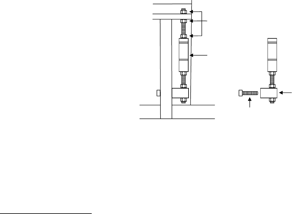
Chapter 6: Troubleshooting
Load Cell Replacement
Loosen Nuts
and Remove
Threaded Rod
Drag Load Cell
Mounting
Block
Remove Two Bolts
Figure 6-7: Drag Load Cell Assembly
19.
Unscrew the threaded rod to remove it from the load cell.
20.
Remove the two bolts that secure the lower mounting block to the carriage.
21.
Remove the load cell and lower mounting block through the opening in the back
side of the carriage.
22.
Loosen the jam nut at the bottom of the load cell and unscrew the load cell from
the threaded rod connected to the mounting block.
Installing a New Drag Load
Cell (Simplex)
1.
Screw the threaded rod that is connected to the lower mounting block into the hole
at the bottom of the new load cell (see Figure 6-7). Make sure that the end of the
threaded rod does not extend into the gap in the load cell.
2.
Position the load cell below the upper carriage mount in the scale carriage. Make
sure that the load cell cable faces the back of the carriage.
3.
Insert the threaded rod through the hole in the upper carriage mount. Place a nut
on the threaded rod above the carriage mount and two nuts below the carriage
mount.
4.
Screw the lower end of the threaded rod into the hole in the top of the new load cell.
Again, make sure that the end of the threaded rod does not extend into the gap in
the load cell.
5.
Tighten the three jam nuts that secure the load cell to the upper carriage mount.
Make sure that there is clearance between the sides of the load cell and the
carriage.
6.
Replace the top flexure, making sure to insert any shims in their original locations.
7.
If the load cell is on the opposite side of the carriage from the telemetry enclosure,
route the load cell cable through the scale carriage under the cover plate that you
removed.
8.
Insert the load cell cable through the cord grip into the telemetry enclosure.
(3/05) 6-13
METTLER TOLEDO MCFA Forklift Scale Service Manual
9.
Wire the load cell cable to the terminal strip on the printed circuit board (PCB)
inside the telemetry enclosure. Connect the wires according to the wiring codes in
Figure 6-2. To connect a wire, insert the tip of a flat-blade screwdriver into the
appropriate slot in the terminal and insert the wire into the opening across from the
slot.
10.
Tighten the six nuts on the cord-grip clamp bar (see Figure 6-3). Use a nut driver
to tighten the nuts. Be careful to tighten the nuts only to the point at which the
cables will not slide through the cord grips. Do not overtighten the nuts.
11.
Use the socket head screw to secure the telemetry enclosure to the carriage.
12.
Replace the PCB in the enclosure and secure it with the five Phillips head screws. If
you disconnected the battery wire and inclinometer from the PCB, reconnect them.
13.
Coil any excess cable and store it in the open area of the carriage where the cover
plate was removed. Replace the cover plate and secure it with six Phillips head
screws.
14.
Use the crane to lift the carriage and slide it up into the mast from the bottom of the
mast. Block the carriage to hold it in position.
15.
Route the chains up and over the pulleys.
16.
Insert each chain anchor into its mounting hole in the mast, and screw a nut onto
the bottom end of each threaded anchor (see Figure 6-4). Tighten the jam nuts
against the mast to secure the chains.
17.
Bolt the lower mounting block to the carriage and tighten the jam nuts (see Figure
6-7).
18.
After the scale carriage is secured to the mast, carefully remove the sling and any
additional blocking. Replace the forks on the carriage.
19.
Insert the battery in the battery compartment.
20.
Power up the scale controller and enter its setup mode. Open the data screen and
check the output for the two drag load cells. The output should be approximately
equal (the target is -60 lb ±40 lb). Adjust the load cells so that they are within
tolerance (refer to the “Adjust Load Cell Force” procedure in this chapter).
(3/05)
6-14
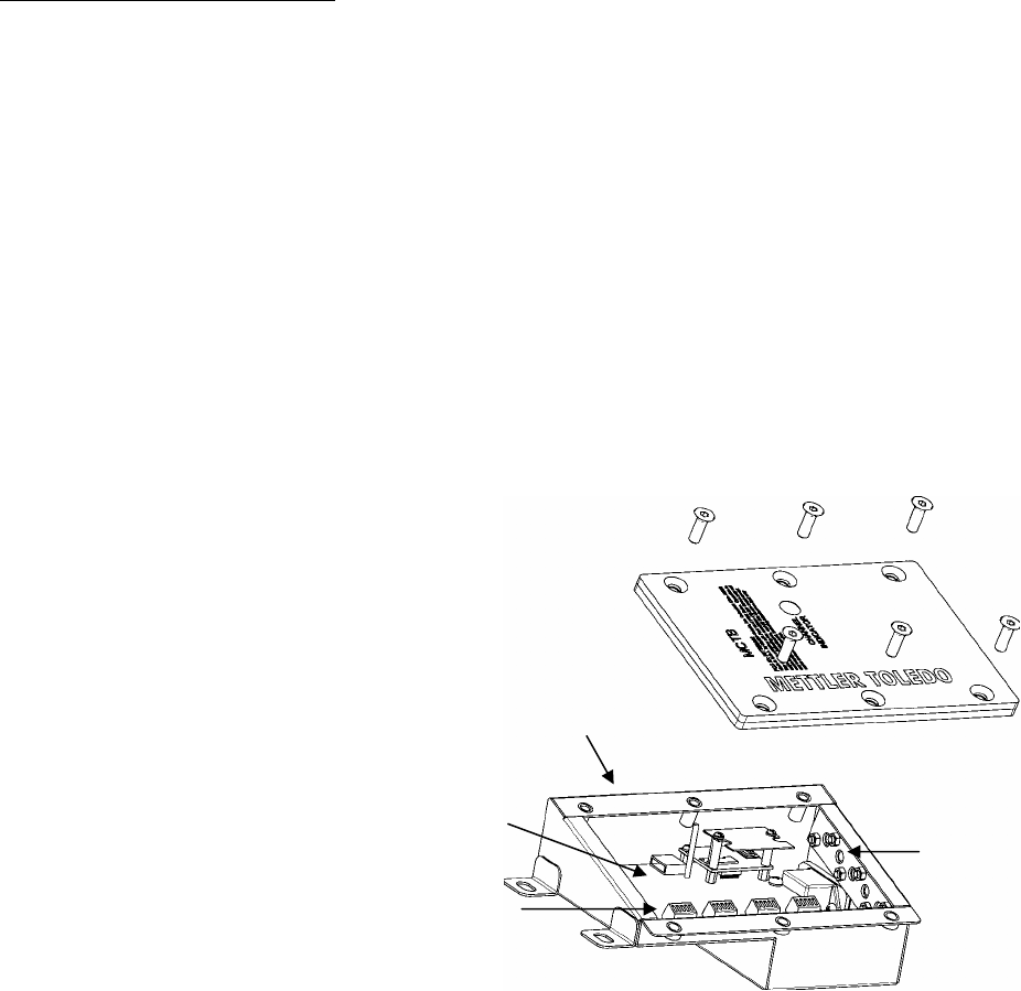
Chapter 6: Troubleshooting
Load Cell Replacement
Removing a Chain Load
Cell (Triplex)
1.
Raise the carriage to a height that will make it easy to reach the load cells and other
scale components.
2.
Shut off the forklift truck’s motor.
3.
Remove the battery by pressing the tab toward the center of the battery and pulling
the battery from the battery compartment.
4.
Remove the cover to the scale’s telemetry enclosure. The cover is held in place by six
flat head cap screws.
5.
The load cell cables are wired to the four terminal strips on the printed circuit board
(PCB) inside the telemetry enclosure (see Figure 6-8). Locate the cable for the load
cell that you are replacing. You should be able to identify it by the tag attached to the
cable. Disconnect the cable’s wires from the terminal strip by inserting the tip of a flat-
blade screwdriver into the slot next to each wire and removing the wire from the
terminal.
Figure 6-8: Telemetry Enclosure
Cord-Grip Clamp Bar
Telemetry Enclosure
PCB
Terminal Strips
6.
Loosen the six nuts on the cord-grip clamp bar. This will loosen the cord grips so that
you can remove the cable.
7.
Pull the load cell cable through the cord grip to remove it from the telemetry
enclosure.
8.
The load cell cables are routed through the scale carriage under the cover plate
located at the bottom of the carriage. Remove the cover plate.
9.
Disconnect the chain anchor from the mast by removing the lower nut from the
threaded anchor (see Figure 6-9).
(3/05) 6-15
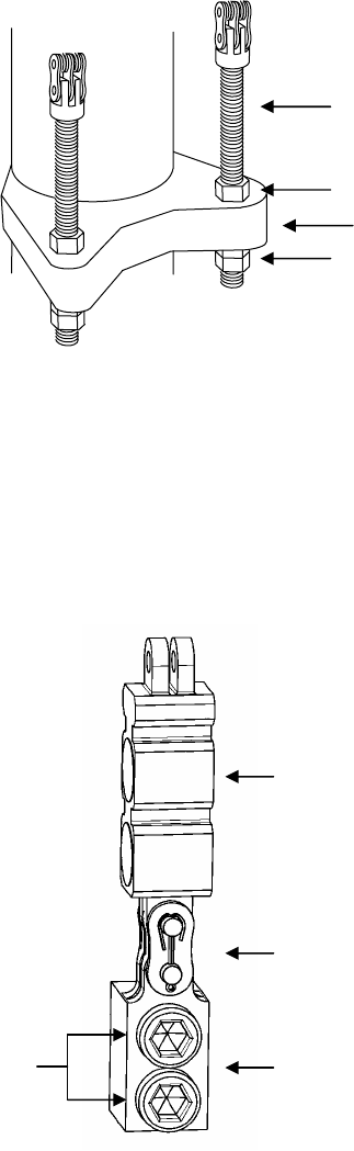
METTLER TOLEDO MCFA Forklift Scale Service Manual
Figure 6-9: Chain Anchor Assembly
10.
Pull the chain up and over the pulley.
11.
Remove the two bolts that secure the chain mount to the carriage. Then remove the
entire assembly (chain mount, load cell, and chain) from the carriage (see Figure 6-
10).
Figure 6-10: Chain Mount Assembly
Bolts
Jam Nut
Mast
Jam Nuts
Chain Anchor
Chain Load Cell
Master Link
Chain Mount
12.
Remove the cotter pin from the master link that secures the load cell to the chain
mount (See Figure 6-11). Take apart the master link, using a C-clamp or similar
device to press the master link through the link plates. Do not use a hammer or other
tool to strike the master link. It could damage the link.
(3/05)
6-16
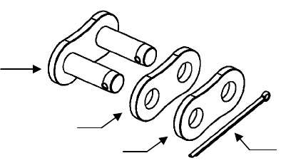
Chapter 6: Troubleshooting
Load Cell Replacement
Figure 6-11: Master Link Assembly
Master Link
Link Plate (Large Holes)
Cotter Pin
Link Plate (Small Holes)
13.
Remove the cotter pin and master link that secure the load cell to the chain.
(3/05) 6-17

METTLER TOLEDO MCFA Forklift Scale Service Manual
Installing a New Chain
Load Cell (Triplex)
1.
Use a master link to connect the new load cell to the chain. The chain should be
connected to the top of the load cell (the end opposite the load cell cable). Assemble
the master link as shown in Figure 6-11. Using a C-clamp or similar device, press
the master link assembly together just enough so that you can insert the cotter pin in
the holes. If the link is too tight, it can bind against the load cell and chain.
2.
Use a master link to connect the other end of the load cell to the chain mount. Make
sure that the load cell cable is facing away from the bolt holes in the chain mount.
Assemble the master link as shown in Figure 6-11. Using a C-clamp or similar
device, press the master link assembly together just enough so that you can insert the
cotter pin in the holes. If the link is too tight, it can bind against the load cell and
chain mount.
3.
Bolt the chain mount to the carriage, using the two bolts that were removed earlier
(see Figure 6-10). Torque all three bolts to 216 ft-lb (or 120% of the prescribed
torque value). Loosen all three bolts so that all torque is relieved. Retighten all bolts
to the prescribed torque of 180 ft-lb. The application of a medium-grade thread locker
is acceptable.
4.
Route the chain up and over the pulley.
5.
Remove the lower nut from the threaded chain anchor. Insert the threaded chain
anchor into the mounting hole in the mast. Place the lower nut on the threaded
anchor and tighten it until both it and the upper nut are tight against the mast (see
Figure 6-9).
6.
Insert the load cell cable through the cord grip into the telemetry enclosure.
7.
Wire the load cell cable to the terminal strip on the printed circuit board (PCB) inside
the telemetry enclosure. Connect the wires according to the wiring codes in Figure 6-2.
To connect a wire, insert the tip of a flat-blade screwdriver into the appropriate slot in
the terminal and insert the wire into the opening across from the slot.
8.
Tighten the six nuts on the cord-grip clamp bar (see Figure 6-8). Use a nut driver to
tighten the nuts. Be careful to tighten the nuts only to the point at which the cables
will not slide through the cord grips. Do not overtighten the nuts.
9.
Coil any excess cable and store it in the open area of the carriage where the cover plate
was removed. Replace the cover plate and secure it with four Phillips head screws.
10.
Replace the cover on the telemetry enclosure and secure it with six flat head screws.
11.
Insert the battery in the battery compartment.
12.
Power up the scale controller and enter its setup mode. Open the data screen and
check the output for the two chain load cells. The output should be approximately
equal (±100 lb). Adjust the tension on the chain connected to the new load cell until
the outputs are within tolerance (refer to the “Adjust Load Cell Force” procedure in this
chapter).
(3/05)
6-18

Chapter 6: Troubleshooting
Load Cell Replacement
Removing a Drag Load Cell
(Triplex)
1.
Remove the forks from the lift truck.
2.
Raise the inner mast high enough to allow room to slide the carriage down and out of
the mast.
3.
Shut off the forklift truck’s motor.
4.
Obtain a crane (or other lifting device) with a capacity of at least 500 lb. Wrap a
sling securely around the upper part of the carriage. Use the crane to raise the sling
high enough that it supports the weight of the carriage.
5.
Remove the battery by pressing the tab toward the center of the battery and pulling
the battery from the battery compartment.
6.
Disconnect the two chain anchors from the mast by removing the lower nut from
each threaded anchor (see Figure 6-9).
7.
Pull the chains up and over the pulleys.
8.
Use the crane to lower the carriage and remove it from the bottom of the mast.
9.
Place the carriage on a stable working surface, with the front side of the carriage
facing downward.
10.
Remove the cover to the scale’s telemetry enclosure. The cover is held in place by six
flat head cap screws. If you are replacing the left drag load cell, you will need to
remove the entire telemetry enclosure to be able to reach the load cell. To remove the
enclosure, you will need to let out some of the excess battery cable that is coiled
inside the enclosure.
11.
The load cell cables are wired to the four terminal strips on the printed circuit board
(PCB) inside the telemetry enclosure (see Figure 6-8). Locate the cable for the load
cell that you are replacing. You should be able to identify it by the tag attached to the
cable. Disconnect the cable’s wires from the terminal strip by inserting the tip of a flat-
blade screwdriver into the slot next to each wire and removing the wire from the
terminal.
12.
Loosen the six nuts on the cord-grip clamp bar. This will loosen the cord grips so that
you can remove the cable.
13.
Pull the load cell cable through the cord grip to remove it from the telemetry
enclosure.
14.
The load cell cables are routed through the scale carriage under the cover plate
located at the top of the carriage. Remove the cover plate.
15.
Remove the top flexure on the side of the scale where you will be replacing the load
cell. Note the position of any shims that are under the flexure so that you can replace
them later.
16.
Loosen the nuts on the threaded rods that anchor the load cell to the upper and lower
carriage mounts (see Figure 6-12). That will allow you to rotate the load cell enough
to grip the top part of the load cell with a 1.25-inch open-end wrench (or clamp).
While gripping the load cell with the wrench, loosen the jam nut that is tightened
against the top of the load cell.
(3/05) 6-19
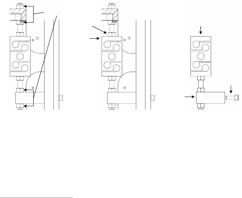
METTLER TOLEDO MCFA Forklift Scale Service Manual
Loosen Nuts Remove
Threaded Rod
Loosen Nut
Grip with
Wrench
Remove
Two
Bolts
Mounting
Block
Figure 6-12: Drag Load Cell Assembly
17.
After loosening the three nuts on the threaded rod connected to the top of the load
cell, unscrew the threaded rod to remove it from the load cell.
18.
Remove the two bolts that secure the lower mounting block to the carriage.
19.
Remove the load cell and lower mounting block through the opening in the back side
of the carriage.
20.
Loosen the jam nut at the bottom of the load cell and unscrew the load cell from the
threaded rod connected to the mounting block. Grip the bottom part of the load cell
with a wrench when loosening the jam nut.
Installing a New Drag Load
Cell (Triplex)
1.
Screw the threaded rod that is connected to the lower mounting block into the hole at
the bottom of the new load cell (see Figure 6-12). Make sure that the end of the
threaded rod does not extend into the gap in the load cell.
2.
Position the load cell below the upper carriage mount in the scale carriage. Make
sure that the load cell cable faces the front of the carriage.
3.
Bolt the lower mounting block to the carriage and tighten the jam nuts (see Figure 6-
12). Grip the bottom part of the load cell with a wrench when tightening the jam nut
against it. Be careful not to damage the load cell by twisting it.
4.
Insert the other threaded rod through the hole in the upper carriage mount. Place a
nut on the threaded rod above the carriage mount and two nuts below the carriage
mount.
5.
Screw the lower end of the threaded rod into the hole in the top of the new load cell.
Again, make sure that the end of the threaded rod does not extend into the gap in the
load cell.
6.
Tighten the three jam nuts that secure the load cell to the upper carriage mount. Grip
the top part of the load cell with a wrench when tightening the jam nut against it. Be
(3/05)
6-20
Chapter 6: Troubleshooting
Load Cell Replacement
careful not to damage the load cell by twisting it. When all nuts are tightened, the
load cell should be positioned squarely.
7.
Replace the top flexure, making sure to insert any shims in their original locations.
8.
Insert the load cell cable through the cord grip into the telemetry enclosure.
9.
Wire the load cell cable to the terminal strip on the printed circuit board (PCB) inside
the telemetry enclosure. Connect the wires according to the wiring codes in Figure 6-
2. To connect a wire, insert the tip of a flat-blade screwdriver into the appropriate slot
in the terminal and insert the wire into the opening across from the slot.
10.
Tighten the six nuts on the cord-grip clamp bar (see Figure 6-8). Use a nut driver to
tighten the nuts. Be careful to tighten the nuts only to the point at which the cables
will not slide through the cord grips. Do not overtighten the nuts. If the telemetry
enclosure was removed, mount it to the scale carriage in its original position.
11.
Coil any excess cable and store it in the open area of the carriage where the top cover
plate was removed. Replace the cover plate and secure it with four Phillips head
screws.
12.
Use the crane to lift the carriage and slide it up into the mast from the bottom of the
mast. Block the carriage to hold it in position.
13.
Route the chains up and over the pulleys.
14.
Insert each chain anchor into its mounting hole in the mast, and screw a nut onto the
bottom end of each threaded anchor (see Figure 6-9). Tighten the jam nuts against
the mast to secure the chains.
15.
After the scale carriage is secured to the mast, carefully remove the sling and any
additional blocking. Replace the forks on the carriage.
16.
Insert the battery in the battery compartment.
17.
Power up the scale controller and enter its setup mode. Open the data screen and
check the output for the two drag load cells. The output should be approximately
equal (the target is -60 lb ±40 lb). Adjust the load cells so that they are within
tolerance (refer to the “Adjust Load Cell Force” procedure in this chapter).
(3/05) 6-21
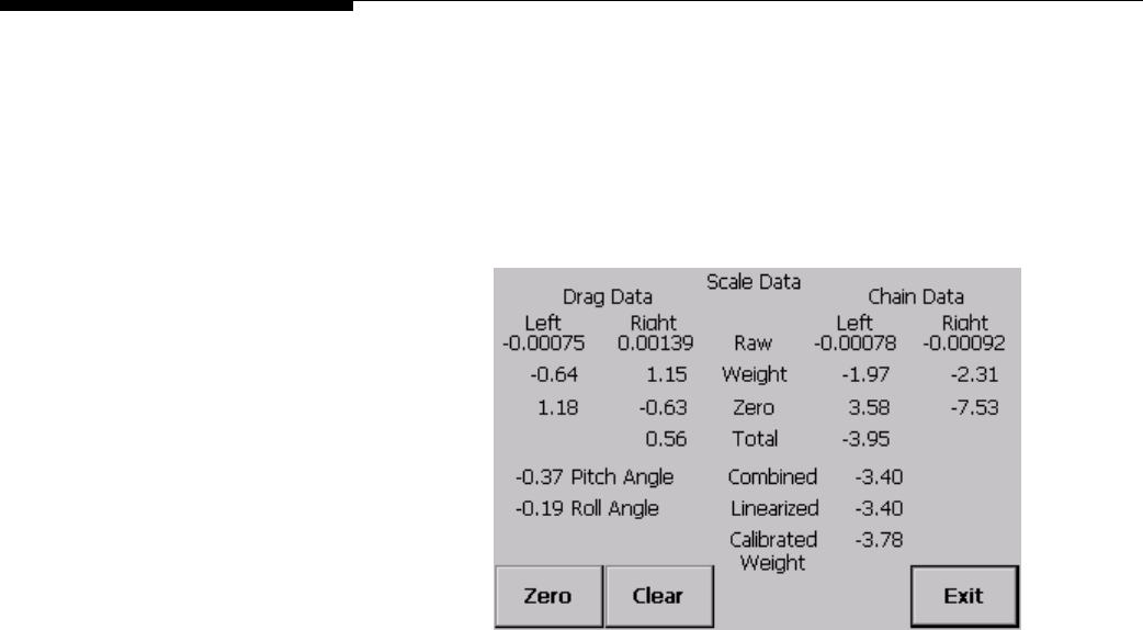
METTLER TOLEDO MCFA Forklift Scale Service Manual
Adjust Load Cell Force
After replacing a load cell, check the scale’s force data to see if adjustments are needed.
1.
Touch the Setup button on the scale controller to enter setup mode.
2.
Open the data screen by touching the Maintenance button, the Diagnostics button,
and the Data Screen button.
3.
Park the forklift truck on a level surface, remove all load from the forks, raise the
forks 12 to 15 inches off the ground, set the mast to the vertical position, and shut
off the forklift truck’s motor.
4.
Touch the Zero button to reset the scale to zero.
5.
Compare the weight readings for the left drag load cell and the right drag load cell.
The reading for each load cell should be approximately -60 lb (±40 lb). If either
load cell is outside this range, adjust the load cell until the reading is within the
range.
•
Each drag load cell is connected to a lower mounting block by a length of
threaded rod. Loosen the jam nut on the top side of the mounting block.
•
Then adjust the jam nut on the bottom side of the mounting block, tightening
the nut to increase the force or loosening the nut to decrease the force. Do not
turn the load cell.
•
After making the adjustment, tighten the upper jam nut against the mounting
block.
6.
Compare the weight readings for the left chain load cell and the right chain load
cell. Each reading should be approximately equal (±100 lb). If necessary, adjust
the chain anchors until both readings are within this range.
•
Loosen the jam nut on the top side of the carriage mounting block.
•
Then adjust the jam nut on the bottom side of the mounting block, tightening
the nut to increase the force or loosening the nut to decrease the force. As the
force on one load cell goes up, the force on the other load cell will go down.
•
After making the adjustment, tighten the upper jam nut against the mounting
block.
7.
Touch the Exit button to close the data screen.
(3/05)
6-22
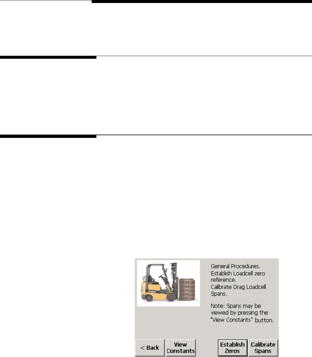
Chapter 7: Calibration
General
7
Calibration
General
A forklift scale is calibrated at the factory and should not need to be recalibrated when it
is installed. As part of the normal maintenance schedule, have a qualified service
technician check the scale’s calibration periodically. Calibration should also be checked
whenever a load cell is replaced. If the scale is within accepted tolerances, there is no
need to recalibrate it.
Calibrate Load Cells
Check the span values for the drag load cells. With the scale controller in setup mode,
open the data screen. Park the forklift truck on a level surface, remove all load from the
forks, set the mast to the vertical position, and then raise and lower the carriage several
times to exercise the scale. Position a block 15 inches high under the bottom roller on
each side of the scale carriage. Touch the Zero button, and then lower the carriage onto
the blocks. The “Calibrated Weight” reading is the sum of the totals for the drag load
cells and the chain load cells. It should be zero (±2 lb). If the reading is out of
tolerance, perform the following calibration procedure:
1.
Touch the Setup button to enter setup mode.
2.
Open the load cell calibration screen by touching the Scale button, the Calibration
button, and the Loadcell button.
3.
Touch the Calibrate Spans button.
(3/05) 7-1
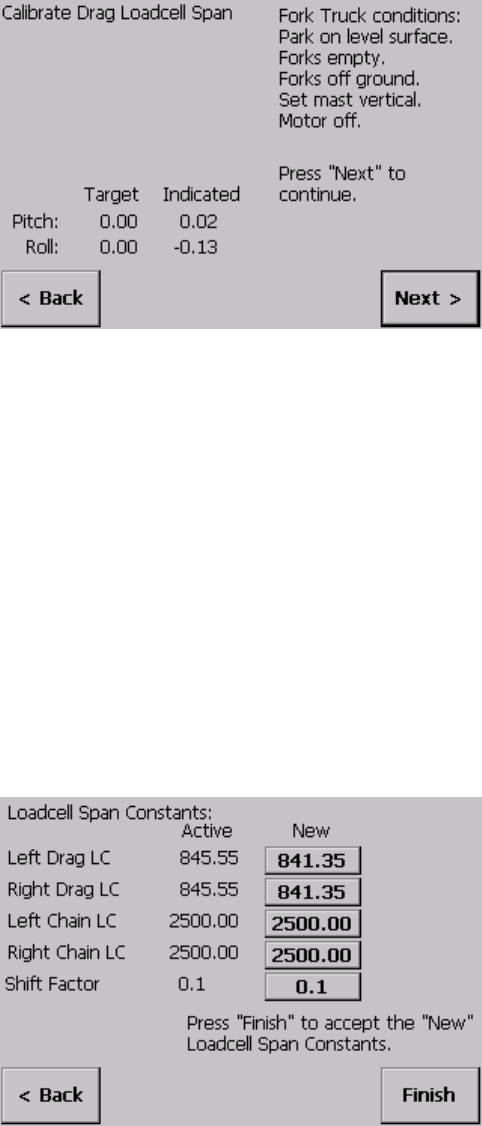
METTLER TOLEDO MCFA Forklift Scale Service Manual
4.
Park the forklift truck on a level surface, remove all load from the forks, set the mast
to the vertical position, and raise the forks slightly more than 15 inches off the
ground.
5.
Position a block 15 inches high under the bottom roller on each side of the scale
carriage. Lower the carriage onto the blocks until the chains are slack, and then
raise the carriage off the blocks (repeat this several times to exercise the scale).
6.
With the carriage raised off the blocks, shut off the forklift truck’s motor. Wait about
15 seconds for the scale to stabilize.
7.
Touch the Next button. The system will count down as it updates the values.
8.
Lower the carriage onto the blocks, and wait about 15 seconds for the scale to
stabilize.
9.
Touch the Next button. The system will count down as it updates the values. The
new drag load cell span constants will then be displayed.
10.
Touch the Finish button to accept the new span values.
11.
Raise the carriage and remove the blocks.
(3/05)
7-2
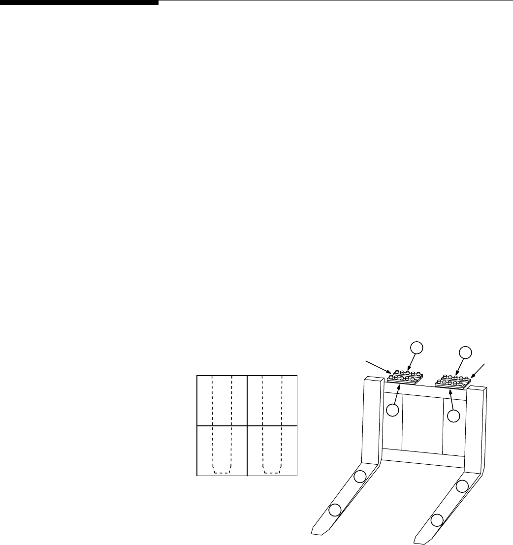
Chapter 7: Calibration
Span Adjustment
Span Adjustment
A correctly adjusted scale will give you the same weight reading no matter where on the
forks you place a test weight. If the weight readings at the shift test locations are out of
tolerance, shift adjust the scale to correct the problem.
Park the forklift truck on a level surface, place a pallet on the forks, raise the forks 12 to
15 inches off the ground, set the mast to the vertical position, and shut off the forklift
truck’s motor. Then check the scale’s repeatability by placing a test weight on the same
location on the pallet several times to make sure that you get the same weight reading
each time.
After verifying the scale’s repeatability, check to see if the scale needs to be shift
adjusted. For shift adjustments, we recommend using test weights equal to one half the
scale’s maximum weighing capacity. The test weights must meet the specified National
Institute of Standards and Technology Handbook 44 accuracy requirements.
NOTE: When performing a shift adjustment, use the weight readings on the data screen
instead of those on the main weighing screen. The weight readings on the data screen
are displayed to two decimal places, although the number in the second decimal place
might not be stable.
Shift Test Locations
Place a pallet or other flat surface (approximately 4 feet by 4 feet) on the forks and
make sure that it is level. Figure 7-1 shows test weight locations (1, 2, 3, and 4) at the
center of each quadrant of the pallet. Place the test weight at location 1 and record the
weight reading. Then move the test weight to location 2 and record the weight reading.
Continue until you have taken a weight reading at each of the four locations.
Flexure
Heel Heel
2
4
1
A D
C
Flexure
B
1
3
4
2
3
Toe Toe
Figure 7-1: Shift Adjustment Locations (Simplex Version Shown)
(3/05) 7-3
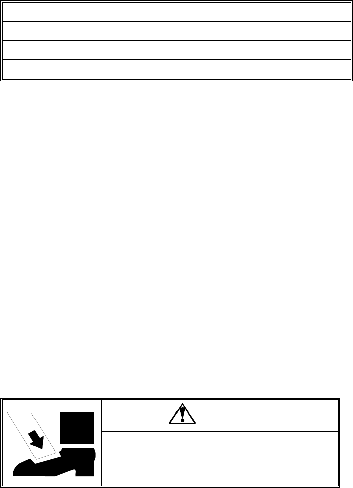
METTLER TOLEDO MCFA Forklift Scale Service Manual
Ideally, the scale will give you the same weight reading at all four locations. The weight
readings at the heel and toe of either or both forks should be within Handbook 44
tolerance requirements (±2.5 lb for weights up to 2,500 lb). If the weight readings are
out of tolerance, you will need to shift adjust the scale. This is done by adding shims to
the flexures at the locations shown in Figure 7-1. To determine where to add shims,
refer to Table 7-1.
If weight reading 1 is greater than 2 → Shim at location A
If weight reading 2 is greater than 1 → Shim at location B
If weight reading 3 is greater than 4 → Shim at location C
If weight reading 4 is greater than 3 → Shim at location D
Table 7-1: Shim Locations
The shims adjust the differences between the weight readings at the heel and toe of an
individual fork. Adjust the weight readings so that they are as near to equal as possible.
If one weight reading is slightly higher, it should be the reading at the toe of the fork.
Shimming at the front of a flexure (location A) will increase the weight reading at the toe
of the fork (location 2). Because the shim affects the entire fork, it will also slightly
increase the weight reading at the heel (location 1).
Shimming at the back of a flexure (location B) will decrease the weight reading at the
toe of the fork (location 2). Because the shim affects the entire fork, it will also slightly
decrease the weight reading at the heel (location 1).
A pallet places load on both forks. So when a pallet is used, shimming under a flexure
will affect the readings at all four test weight locations. For example, shimming at
location A or B will change the readings at locations 1 and 2, but it will also change the
readings at locations 3 and 4 to a lesser extent.
Keep in mind that, in addition to balancing the weight readings at the heel and toe of
each fork, you are also trying to balance the weight readings of the two forks.
Shimming Procedure
Do not remove the bolts from more than one flexure at a time. The flexures connect the
two sections of the scale carriage. If you unbolt the two top or bottom flexures, the
sections of the carriage could separate and cause injury or damage the flexures.
DANGER
DO NOT REMOVE THE BOLTS FROM MORE THAN ONE
FLEXURE AT A TIME WHILE THE CARRIAGE IS INSTALLED
ON THE FORKLIFT. UNBOLTING MORE THAN ONE FLEXURE
COULD RESULT IN BODILY HARM OR PROPERTY DAMAGE.
1.
Remove the bolts from the side of the flexure where shims will be added.
2.
Loosen the bolts on the opposite side of the flexure.
3.
Place a shim under the flexure, aligning the bolt holes in the shim with those in the
flexure. We recommend starting with the thinnest shim and gradually increasing
the shim thickness as needed to balance the weight readings.
(3/05)
7-4
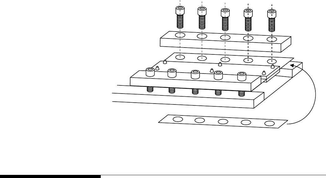
Chapter 7: Calibration
Calibrate Linearity
4.
Replace the bolts that were removed, and tighten all bolts. Torque the bolts to 90 ft-
lb.
5.
Repeat steps 1-4 for the second flexure if needed.
6.
Take new weight readings at all four test weight locations. If the weight readings
are still not equal, repeat the procedure to add additional shimming.
7.
When you have finished shift adjusting the scale, you should get approximately the
same weight reading at all four test weight locations.
Add shim
under flexure
Loosen bolts
on opposite
side of flexure
Remove bolts
to add shim
Figure 7-2: Shimming Procedure (Simplex Version Shown)
Calibrate Linearity
Check the scale for linearity errors. We recommend using five 1,000-lb test weights.
Use the weight readings on the data screen instead of those shown on the main
weighing screen. The weight readings on the data screen are accurate to two decimal
places.
• Park the forklift truck on a level surface, raise the forks 12 to 15 inches off the
ground, set the mast to the vertical position, and shut off the forklift truck’s motor.
Place a pallet on the forks, and use the weight of the pallet as the tare weight.
• Record the net weight with no test weight on the scale. Then add the five test
weights one at a time, recording the net weight after each test weight is added. You
should have weight readings for the following test weights: 0, 1000, 2000, 3000,
4000, and 5000 lb. Then remove the test weights from the scale one at a time,
recording the net weight each time you remove a test weight.
The weight readings should be within Handbook 44 tolerance requirements (±2.5 lb for
weights up to 2,500 lb and ±5 lb for weights greater than 2,500 lb). If the weight
readings are out of tolerance, perform the following calibration procedure:
1.
Park the forklift truck on a level surface, place a pallet on the forks, raise the forks
12 to 15 inches off the ground, set the mast to the vertical position, and shut off the
forklift truck’s motor.
(3/05) 7-5
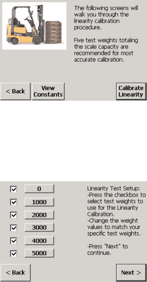
METTLER TOLEDO MCFA Forklift Scale Service Manual
2.
Touch the Setup button on the scale controller to enter setup mode.
3.
Open the linearity calibration screen by touching the Scale button, the Calibration
button, and the Linearity button.
4.
Touch the Calibrate Linearity button to display the linearity test setup. For the
default test setup, all six boxes will be checked and the following weight values will
be listed on the buttons next to the boxes: 0, 1000, 2000, 3000, 4000, 5000. If
you plan to use a different range of weights, reconfigure the test setup to match
those weights. You can select or deselect a step by touching the check box. You
can change a weight value by touching the button to open a keypad that will allow
you to enter a new weight value.
When the correct weight values are displayed, touch the Next button to continue.
(3/05)
7-6
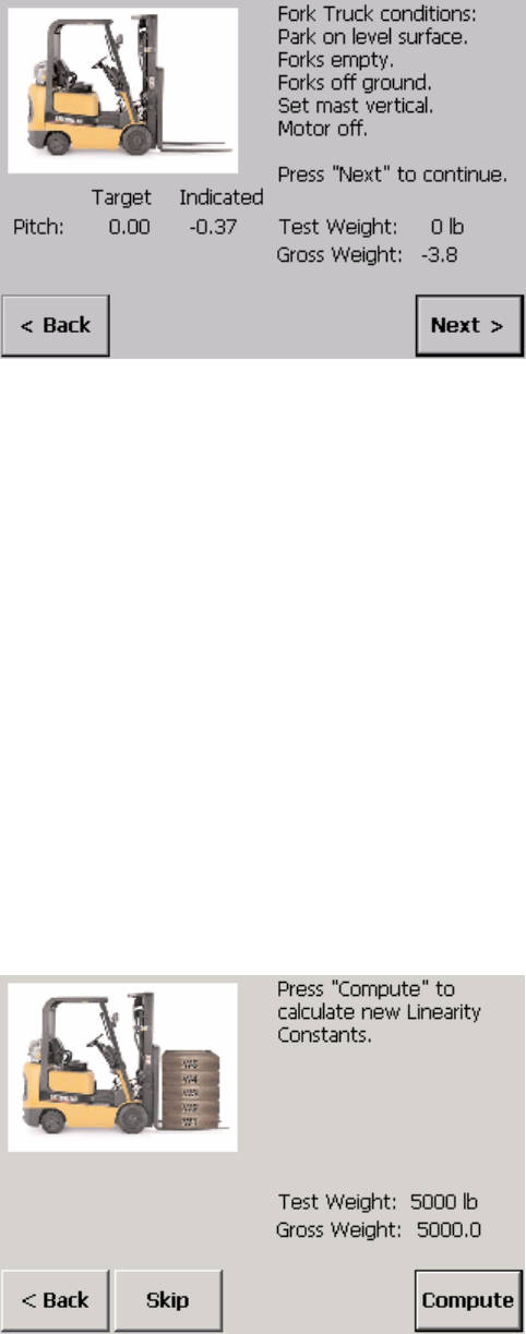
Chapter 7: Calibration
Calibrate Linearity
5.
With zero test weight on the scale, touch the Next button. The system will count
down as it updates the values.
6.
Add test weight so that the total weight on the scale equals 1,000 lb, allow the
scale to stabilize, and then touch the Next button. The system will count down as it
updates the values.
7.
Add test weight so that the total weight on the scale equals 2,000 lb, allow the
scale to stabilize, and then touch the Next button. The system will count down as it
updates the values.
8.
Add test weight so that the total weight on the scale equals 3,000 lb, allow the
scale to stabilize, and then touch the Next button. The system will count down as it
updates the values.
9.
Add test weight so that the total weight on the scale equals 4,000 lb, allow the
scale to stabilize, and then touch the Next button. The system will count down as it
updates the values.
10.
Add test weight so that the total weight on the scale equals 5,000 lb, allow the
scale to stabilize, and then touch the Next button. The system will count down as it
updates the values.
11.
Touch the Compute button to calculate the new linearity constants.
(3/05) 7-7
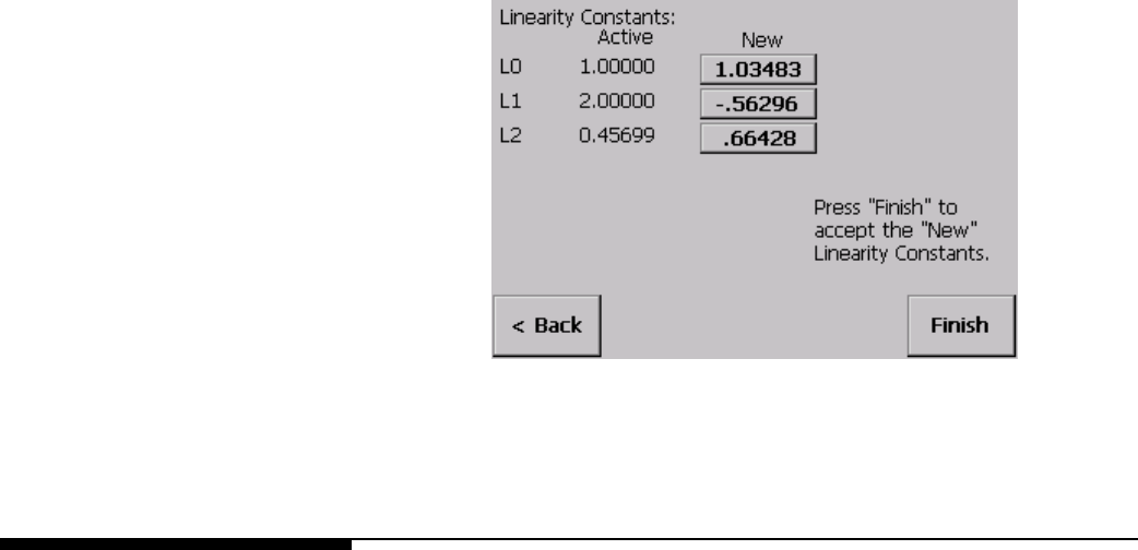
METTLER TOLEDO MCFA Forklift Scale Service Manual
12.
The new linearity constants will be displayed. Touch the Finish button to accept the
new constants.
Calibrate Angles
Determine if angle calibration is needed by checking the scale’s accuracy with the mast
set at several angles. Mast pitch and roll angles are shown on the data screen. Use the
same test weight for each mast setting. The recommended test weight is full scale
capacity (5,000 lb). To change the test weight amount, touch the test weight button on
the angle calibration screen and then use the keypad to enter a new weight value. Use
the weight readings on the data screen instead of those shown on the main weighing
screen. The weight readings on the data screen are accurate to two decimal places.
• Park the forklift truck on a level surface, set the mast to the vertical position, and
raise the forks 12 to 15 inches off the ground. The forklift truck’s motor should be
shut off when taking weight readings. Place a pallet on the forks, and zero the
scale. Place the test weight on the scale, and record the weight.
• Check the mast pitch: Remove the test weight, set the mast 5 degrees backward,
and zero the scale. Then place the test weight on the scale, and record the weight.
Remove the test weight, set the mast 5 degrees forward, and zero the scale. Then
place the test weight on the scale, and record the weight.
• Check the mast roll: Set the mast to the vertical position. Remove the test weight,
position the forklift truck on a ramp so that the mast is angled approximately 3
degrees to the right, and zero the scale. Then place the test weight on the scale,
and record the weight. Remove the test weight, position the forklift truck on a ramp
so that the mast is angled approximately 3 degrees to the left, and zero the scale.
Then place the test weight on the scale, and record the weight.
The weight readings should be within Handbook 44 tolerance requirements (±2.5 lb for
weights up to 2,500 lb and ±5 lb for weights greater than 2,500 lb). If the weight
readings are out of tolerance, perform the calibration procedures for mast pitch or for
both mast pitch and mast roll. The angle calibration procedure compensates for any
variation in weight readings that might occur when the mast is set at different angles.
Use the same test weight for each mast setting. The recommended test weight is full
scale capacity (5,000 lb).
(3/05)
7-8
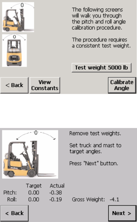
Chapter 7: Calibration
Calibrate Angles
Mast Pitch
1.
Park the forklift truck on a level surface, place a pallet on the forks, raise the forks
12 to 15 inches off the ground, set the mast to the vertical position, and shut off the
forklift truck’s motor.
2.
Touch the Setup button on the scale controller to enter setup mode.
3.
Open the angle calibration screen by touching the Scale button, the Calibration
button, and the Angle button. Make sure that the test weight displayed on the
screen equals the test weight being used for the calibration procedure. You can
change the weight by touching the Test Weight button to open a keypad.
4.
Touch the Calibrate Angle button.
5.
Touch the Next button. The system will count down as it updates the zero load
values.
6.
Add the test weight, allow the scale to stabilize, and then touch the Next button.
The system will count down as it updates the loaded values.
(3/05) 7-9
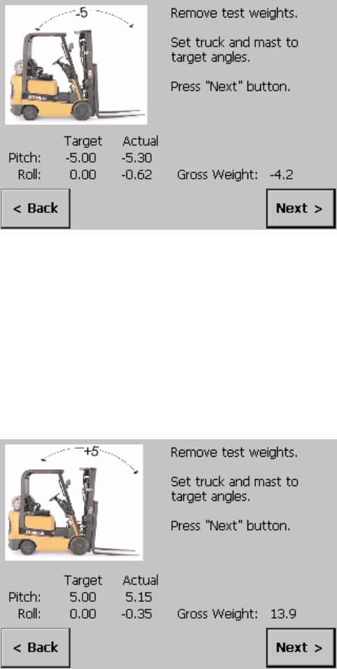
METTLER TOLEDO MCFA Forklift Scale Service Manual
7.
Remove the test weight from the scale.
8.
Set the mast so that it is angled approximately 5 degrees backward. Shut off the
forklift truck’s motor.
9.
Touch the Next button. The system will count down as it updates the zero load
values.
10.
Add the test weight, allow the scale to stabilize, and then touch the Next button.
The system will count down as it updates the loaded values.
11.
Remove the test weight from the scale.
12.
Set the mast so that it is angled approximately 5 degrees forward. Shut off the
forklift truck’s motor.
13.
Touch the Next button. The system will count down as it updates the zero load
values.
14.
Add the test weight, allow the scale to stabilize, and then touch the Next button.
The system will count down as it updates the loaded values.
(3/05)
7-10
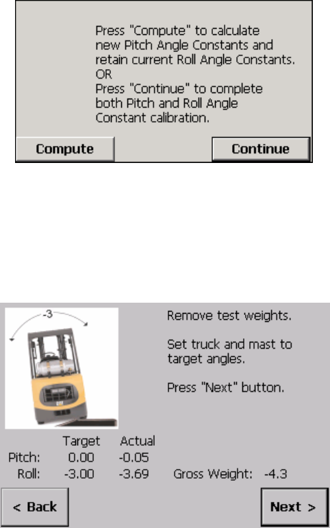
Chapter 7: Calibration
Calibrate Angles
15.
Touch the Compute button to calculate the new pitch angle constants, or touch the
Continue button to continue calibrating both pitch and roll angles. If you touch the
Compute button, go to Step 25.
Mast Roll
16.
Remove the test weight from the scale.
17.
Position the forklift truck on a ramp so that the mast is angled approximately 3
degrees to the right. Shut off the forklift truck’s motor.
18.
Touch the Next button. The system will count down as it updates the zero load
values.
19.
Add the test weight, allow the scale to stabilize, and then touch the Next button.
The system will count down as it updates the loaded values.
(3/05) 7-11
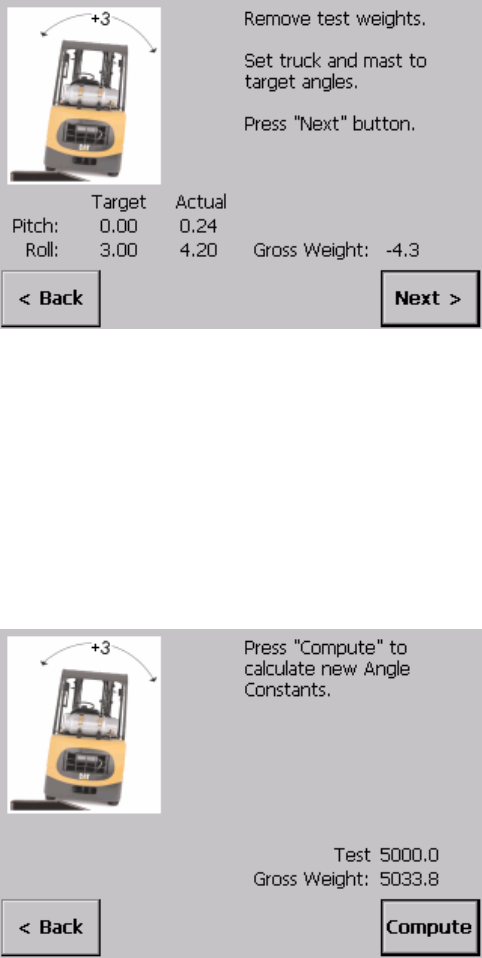
METTLER TOLEDO MCFA Forklift Scale Service Manual
20.
Remove the test weight from the scale.
21.
Position the forklift truck on a ramp so that the mast is angled approximately 3
degrees to the left. Shut off the forklift truck’s motor.
22.
Touch the Next button. The system will count down as it updates the zero load
values.
23.
Add the test weight, allow the scale to stabilize, and then touch the Next button.
The system will count down as it updates the loaded values.
24.
Touch the Compute button to calculate the new pitch and roll angle constants.
(3/05)
7-12
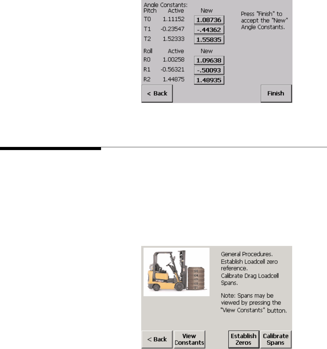
Chapter 7: Calibration
Establish Zero
25.
Touch the Finish button to accept the new constants.
Establish Zero
After performing any of the calibration procedures, establish a zero constant for the
scale. Park the forklift truck on a level surface, remove all load from the forks, set the
mast to the vertical position, raise the forks 12 to 15 inches off the ground, and shut off
the forklift truck’s motor.
1.
Touch the Setup button on the scale controller to enter setup mode.
2.
Open the load cell calibration screen by touching the Scale button, the Calibration
button, and the Loadcell button.
3.
Touch the Establish Zeros button to display the load cell zero constants.
(3/05) 7-13
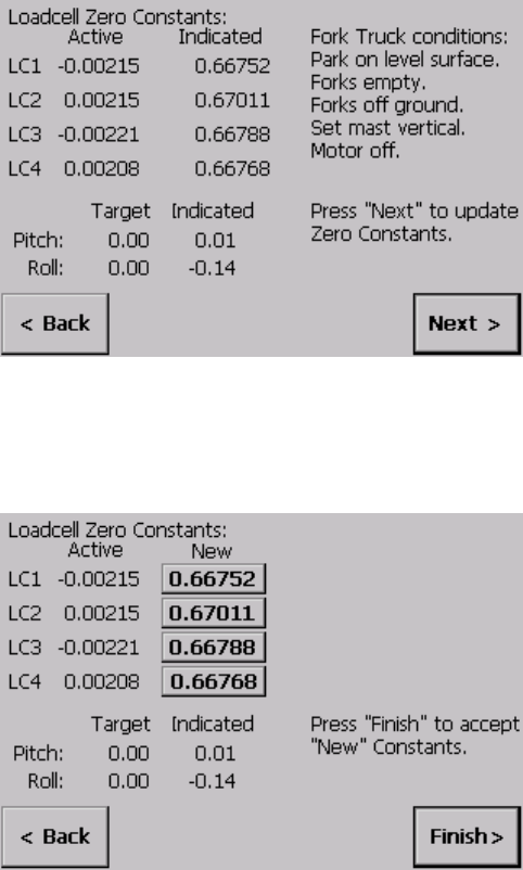
METTLER TOLEDO MCFA Forklift Scale Service Manual
4.
Touch the Next button to update the constants. The system will count down as it
updates the values.
5.
The new zero constants will be displayed. Touch the Finish button to save the new
constants.
NOTE: Be sure to save the new calibration data when you exit setup mode.
(3/05)
7-14
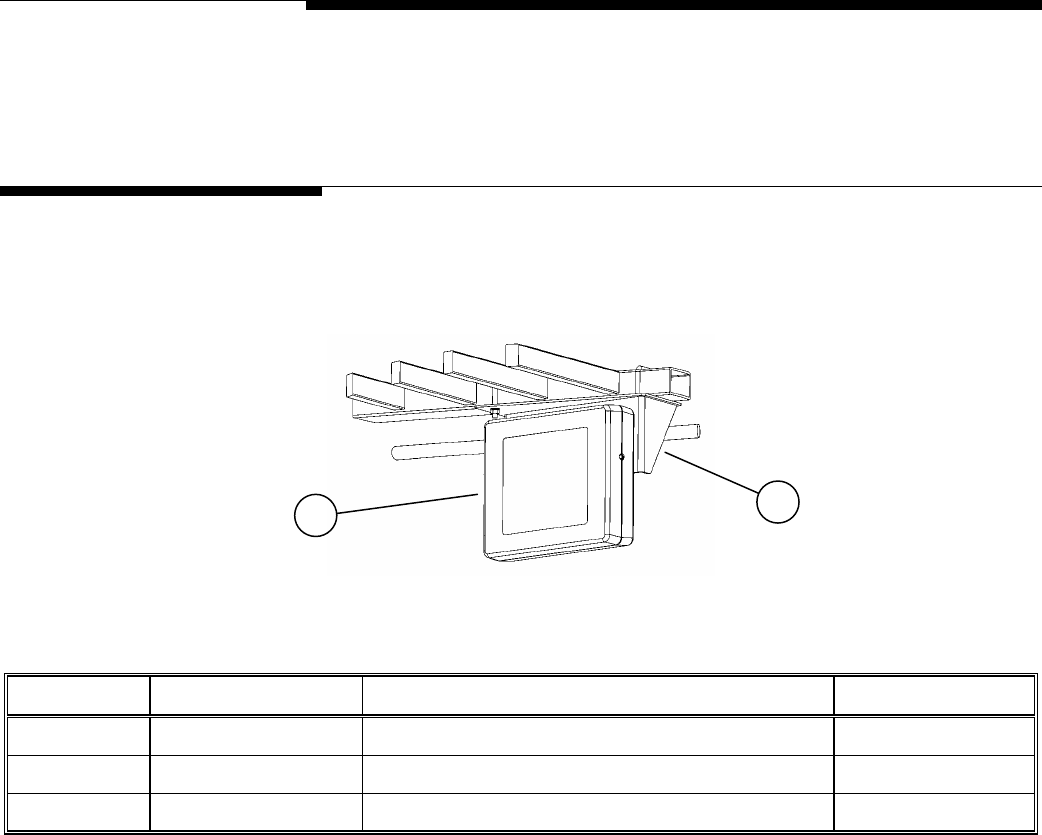
Chapter 8: Service Parts
Scale Controller
8
Service Parts
Scale Controller
2
1
Figure 8-1: Scale Controller and Mounting Bracket
Ref. No. Part Number Description Qty.
1 MCPC0001000 Scale Controller 1
2 TA205236 Mounting Bracket 1
-- MCKT0001000 USB Assembly (optional) 1
Table 8-1: Scale Controller and Mounting Bracket
(3/05) 8-1
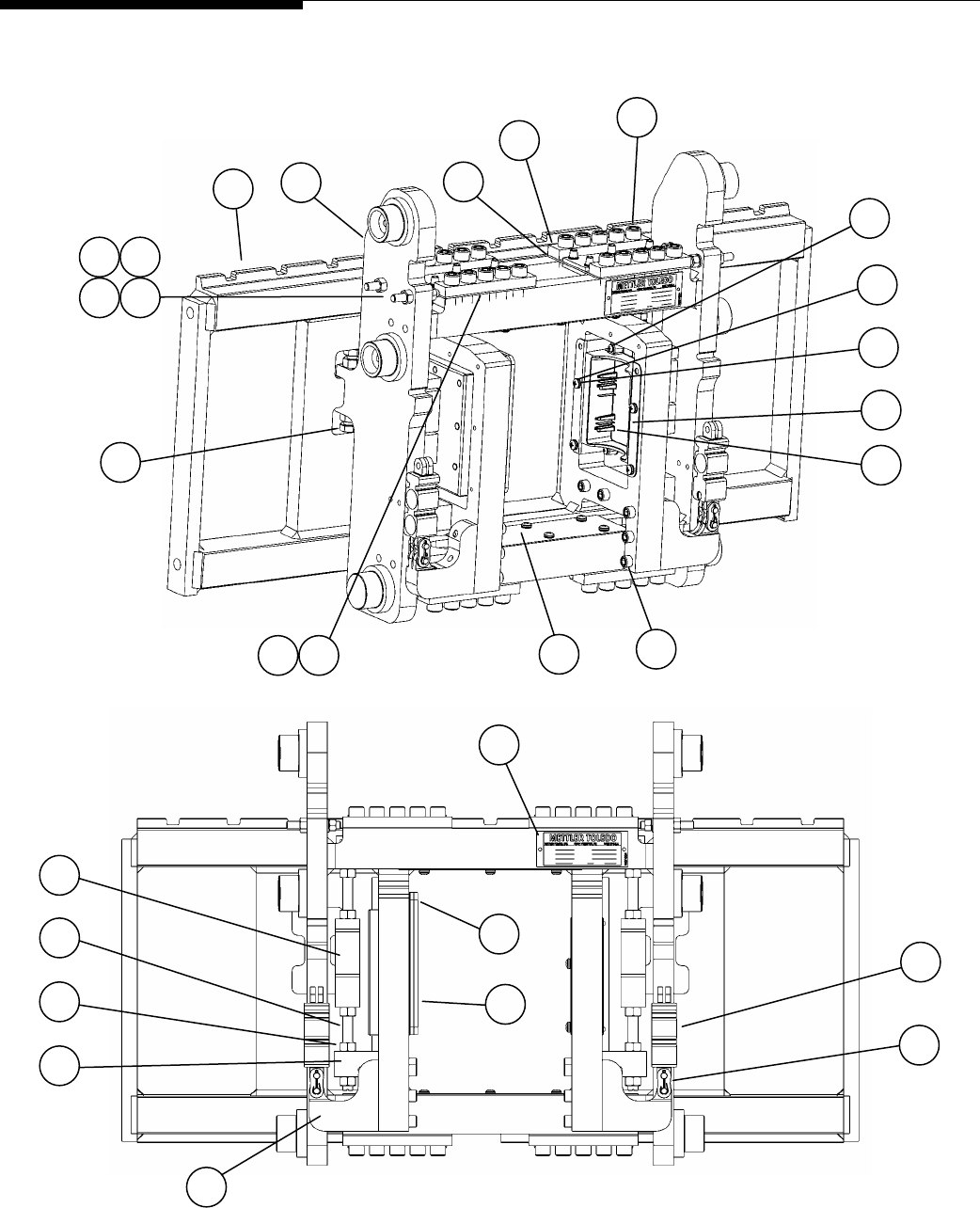
METTLER TOLEDO MCFA Forklift Scale Service Manual
Scale Carriage
20
4
6
13
18 16
1
22
3
25
5
2
9
8
11 10
27 28
12 19
7
29
24
15
23
21
17
26
14
Figure 8-2: Forklift Scale Carriage Assembly (Simplex Version)
(3/05)
8-2

Chapter 8: Service Parts
Scale Carriage
Ref. No. Part Number Description Qty.
1 MZ0901010594 Round Phillips Head Machine Screw, 10-32 x 0.62, SS 4
2 MZ0901010592 Socket Head Cap Screw, 1/2-20 x 1.25 40
3 MZ0901010596 Round Phillips Head Machine Screw, 1/4-20 x 0.50, SS 16
4 MZ0901010591 Socket Head Cap Screw, 3/8-24 x 2.5 10
5 TA205240 Discharge Cradle, Simplex (Atlas) 1
6 TN205216 Cover Plate, Simplex (Atlas) 2
7 MN31004 Data Label 1
8 TA205220 Flexure Assembly, Simplex (MCFA) 4
9 TA205221 Flexure Clamp Bar, Simplex (MCFA) 8
10 T205224-001 Flexure Shim, 0.001 inch thick 4
11 T205224-003 Flexure Shim, 0.003 inch thick 4
12 TN205207 Side Roller Stud, FLT 4
13 TN205253 Bumper Bolt, FLT, MC 4
14 TN205208 Drag Cell Mounting Stud, FLT, MC, SG 4
15 TA205222 Chain Mount, FLT, MC, SG 2
16 TC205202 Carriage Frame, FLT, MC, SGL, DD 1
17 TA205213 Drag Mount, FLT, MC, SG 2
18 TC205214 Carriage Frame, FLT, MC, SGL, LV 1
19 MZ0901030076 Lock Washer, 1/2 Hel. Spring, SS 4
20 16771500A Drag Load Cell, 1,250 lb, Double S, TSD 2
21 16771600A Chain Load Cell, 5,000 lb, Clevis, TSF 2
22 MZ0901030081 Lock Washer, 1/4 Hel. Spring, SS 16
23 TN205252 Master Link, Kit of Parts 2
24 TB205230 Telemetry Enclosure Assembly, MCFA Simplex 1
25 TA205237 Discharge Cradle Mounting Tray, Simplex 1
26 MZ0901020132 Nut, 1/2-20, ZN 16
27 MZ0901020016 Nut, 3/8-16, SS 4
28 MZ0901020135 Nut, M10 x 1.25, SS 4
29 MZ0901010595 Socket Head Cap Screw, 1/4-20 x 0.5, SS 1
-- TB205247 Battery Pack 2
-- TA205241 Battery Charger 1
Table 8-2: Forklift Scale Carriage Assembly (Simplex Version)
(3/05) 8-3
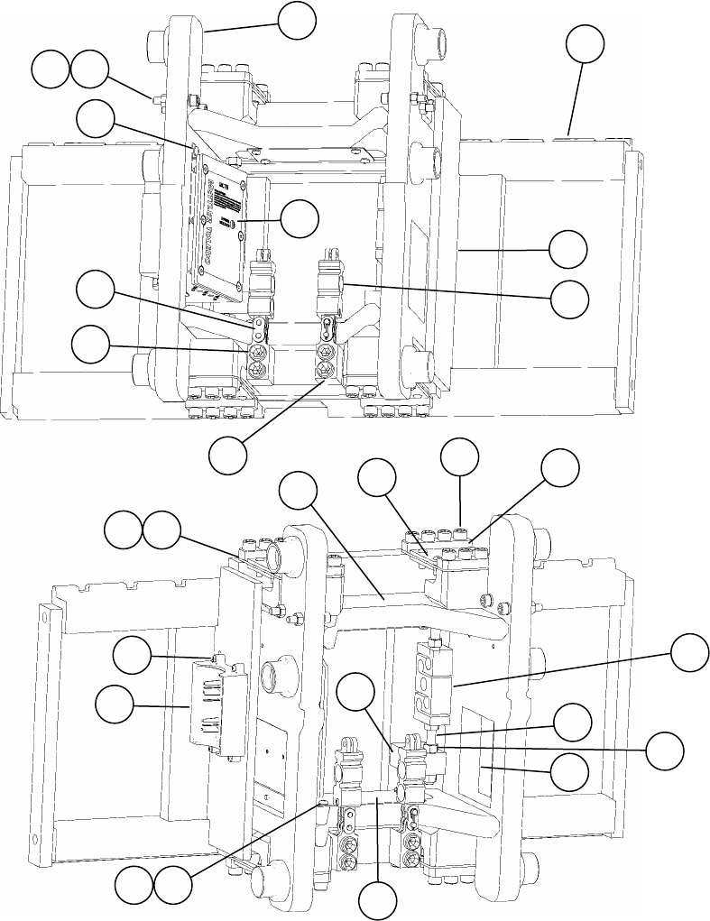
METTLER TOLEDO MCFA Forklift Scale Service Manual
19
4
7
17
15
1
21
3
6
2
10
9
12
11
8
23
14
24
20
16
13
27
26
25
18
5
22
Figure 8-3: Forklift Scale Carriage Assembly (Triplex Version)
(3/05)
8-4

Chapter 8: Service Parts
Scale Carriage
Ref. No. Part Number Description Qty.
1 T205279-001 Flexure Shim, 0.001 inch thick 4
2 T205279-003 Flexure Shim, 0.003 inch thick 4
3 TB206636 Telemetry Enclosure Assembly, MCFA Triplex 1
4 MZ0901030081 Lock Washer, 1/4 Hel. Spring, SS 11
5 MZ0901010594 Round Phillips Head Machine Screw, 10-32 x 0.62, SS 4
6 MZ0901010596 Round Phillips Head Machine Screw, 1/4-20 x 0.50, SS 8
7 MZ0901010595 Socket Head Cap Screw, 1/4-20 x 0.50, SS 3
8 MZ0901020135 Nut, M10 x 1.25, ZN 4
9 MN31004 Data Label 1
10 MZ0901020132 Nut, 1/2-20, ZN 16
11 MZ0901010611 Socket Head Cap Screw, 3/8-24 x 1.0 4
12 MZ0901010620 Socket Head Cap Screw, M10 x 1.25 x 50 4
13 TN205253 Bumper Bolt, FLT, MC 4
14 MZ0901010592 Socket Head Cap Screw, 1/2-20 x 1.25 32
15 TN205252 Master Link, Kit of Parts 2
16 TN205295 Drag Cell Mounting Stud, FLT, MC, TPL 4
17 TN205297 Cover Plate, FLT, MC, TPL 2
18 MZ0901010608 Socket Head Cap Screw, 5/8-18 x 2.0, Gr. 8 4
19 TN205292 Flexure Clamp Bar, MCFA, Triplex 8
20 TA205294 Chain Hanger, FLT, MC, TPL 2
21 16771600A Chain Load Cell, 5,000 lb, Clevis, TSF 2
22 TA205240 Discharge Cradle, Simplex (Atlas) 1
23 TA205293 Drag Mount, FLT, MC, TPL 2
24 16771500A Drag Load Cell, 1,250 lb, Double S, TSD 2
25 TA205291 Flexure Assembly, MCFA, Triplex 4
26 TC205284 Carriage Frame, FLT, MC, TPL, DD 1
27 TC205287 Carriage Frame, FLT, MC, TPL, LV 1
-- TB205247 Battery Pack 2
-- TA205241 Battery Charger 1
Table 8-3: Forklift Scale Carriage Assembly (Triplex Version)
(3/05) 8-5
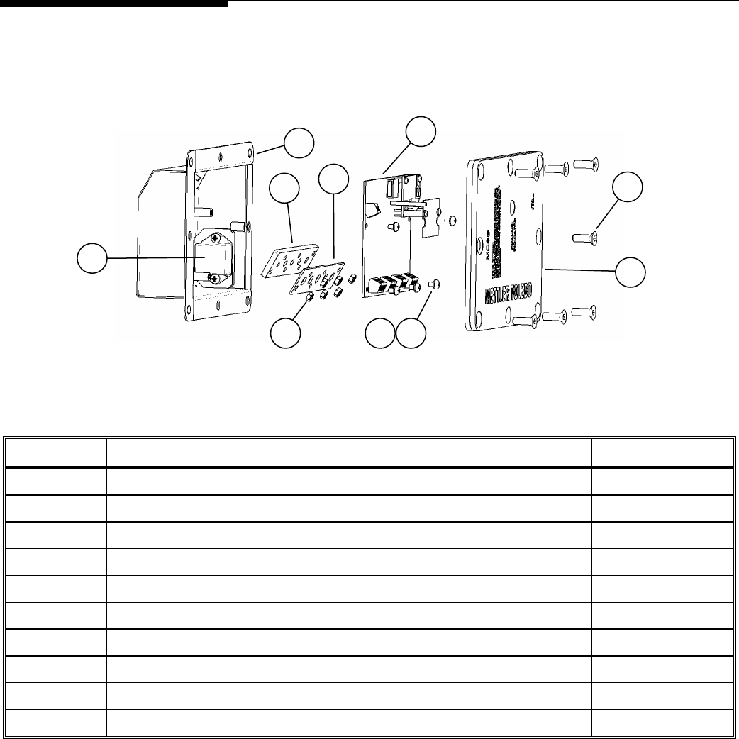
METTLER TOLEDO MCFA Forklift Scale Service Manual
Telemetry Enclosure
6
2
5
7
9
10
1
3 4 8
Figure 8-4: Telemetry Enclosure (Simplex Version)
Ref. No. Part Number Description Qty.
1 TA205256 Two-Axis Inclinometer 1
2 TB205228 Telemetry Enclosure, FLT, MC 1
3 MZ0901030133 Int. Tooth Lock Washer, M4 7
4 MZ0901010597 Round Phillips Head Machine Screw, M4 x 0.7 x 6 mm 7
5 TA205233 Telemetry Box Seal, MCFA, SGL 1
6 TA205229 Telemetry Enclosure Cable Gasket, MCFA, SGL 1
7 TB205254 Telemetry Board, MT0002 1
8 MZ0901020098 Nut, M4, SS 6
9 MZ0901010326 Flat Head Screw, 1/4-20 x 0.75 7
10 TA205261 Telemetry Enclosure Cover Assembly 1
Table 8-4: Telemetry Enclosure (Simplex Version)
(3/05)
8-6
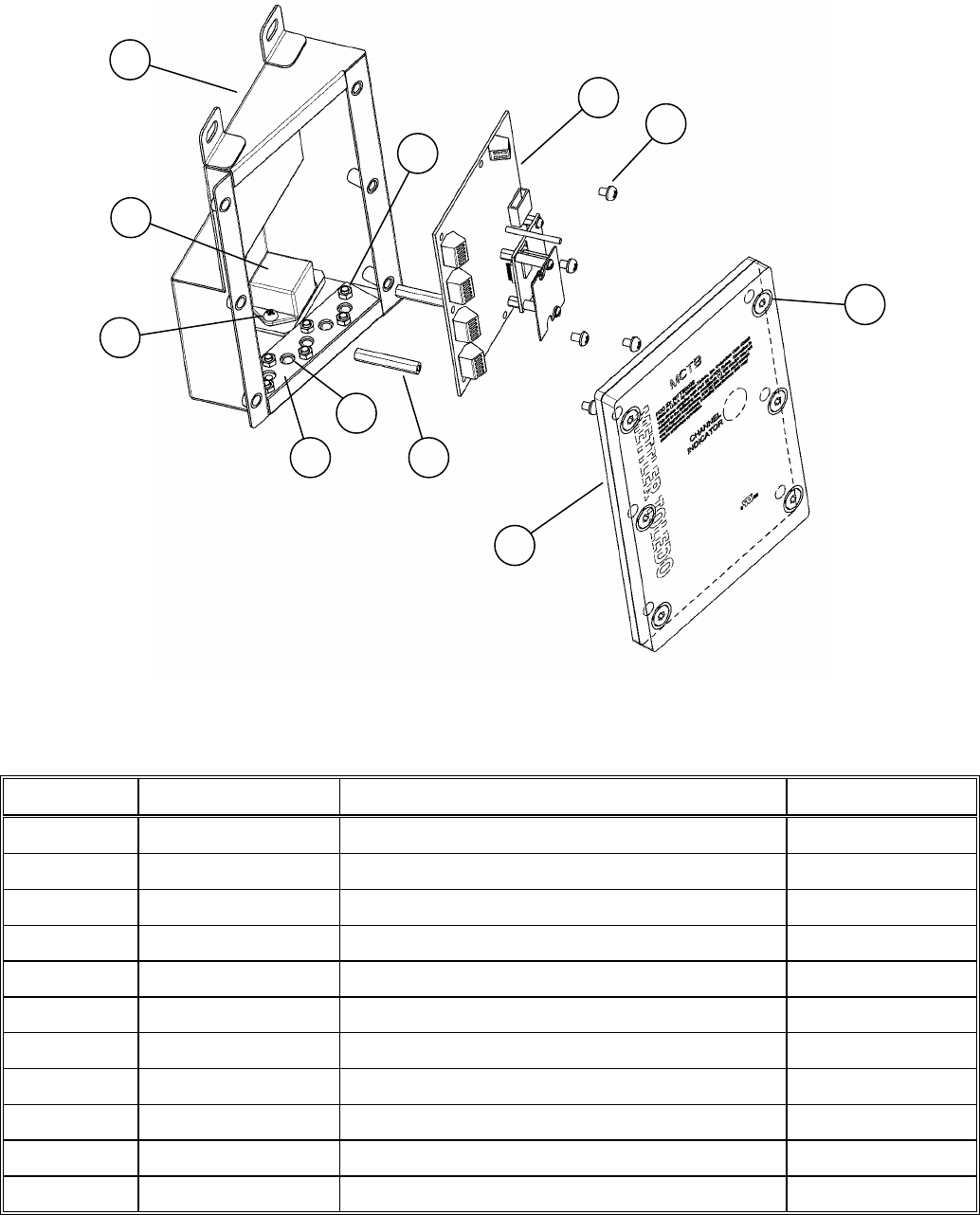
Chapter 8: Service Parts
Telemetry Enclosure
9
2
6
3
1
10
11
4
7
8 5
Figure 8-5: Telemetry Enclosure (Triplex Version)
Ref. No. Part Number Description Qty.
1 TA205256 Two-Axis Inclinometer 1
2 MZ0901030133 Int. Tooth Lock Washer, M4 5
3 MZ0901020098 Nut, M4, SS 6
4 MZ0901010597 Round Phillips Head Machine Screw, M4 x 0.7 x 6 mm 7
5 MZ0902000052 Standoff, M4 x 0.7 x 37 2
6 TB205254 Telemetry Board, MT0002 1
7 TA206638 Telemetry Cable Gasket, MCFA, TPL 1
8 TA206637 Telemetry Cable Clamp Plate, MCFA, TPL 1
9 TC206631 Telemetry Enclosure, 2.5 Ton, MCFA, Triplex 1
10 TA206649 Telemetry Enclosure Cover Assembly, Triplex 1
11 MZ0901010326 Flat Head Screw, 1/4-20 x 0.75 6
Table 8-5: Telemetry Enclosure (Triplex Version)
(3/05) 8-7
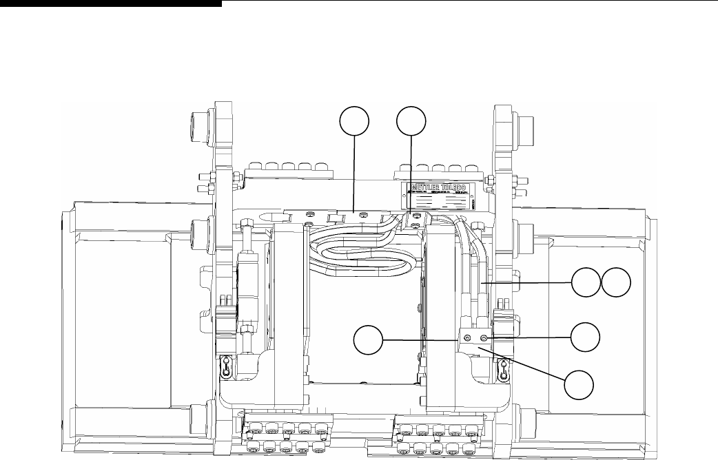
METTLER TOLEDO MCFA Forklift Scale Service Manual
Side Shifter Kit
5 6
1 2
8
3
7
Figure 8-6: Side Shifter Assembly Kit (Simplex Version)
(3/05)
8-8
Chapter 8: Service Parts
Side Shifter Kit
Ref. No. Part Number Description Qty.
1 (See Table 8-7) Mast-to-Scale Hose Assembly 2
2 T205263-001 Scale-to-Shifter Hose Assembly 2
3 TN205269 Manifold, Right 1
4 TN205270 Manifold, Left (Not Shown) 1
5 TN205225 Middle Cover Plate 2
6 TN205226 Hose Strap 1
7 MZ0901010333 Socket Head Cap Screw, 5/16-18 x 1.5 1
8 MZ1405000175 Cap 2
Table 8-6: Side Shifter Assembly Kit (Simplex Version)
MCFA Mast Model MT Hydraulic Kit
Mercury Victoria Magellan Right Left
Mast-to-Scale
Hose Assembly
3A25B20 -- -- MCAC0006 MCAC0007 T205262-001
-- 5A25C20 -- MCAC0008 MCAC0009 T205262-002
-- -- 5V25B20 MCAC0010 MCAC0011 T205262-003
3A25B26 -- -- MCAC0012 MCAC0013 T205262-004
-- 5A25C26 -- MCAC0014 MCAC0015 T205262-005
-- -- 5V25B26 MCAC0016 MCAC0017 T205262-006
3A25B28 5A25C28 -- MCAC0018 MCAC0019 T205262-007
-- -- 5V25B30 MCAC0020 MCAC0021 T205262-008
3A25B30 5A25C30 -- MCAC0022 MCAC0023 T205262-009
-- -- 5V25B33 MCAC0024 MCAC0025 T205262-010
3A25B33 5A25C33 -- MCAC0026 MCAC0027 T205262-011
-- -- 5V25B35 MCAC0028 MCAC0029 T205262-012
3A25B35 5A25C35 -- MCAC0030 MCAC0031 T205262-013
-- -- 5V25B37 MCAC0032 MCAC0033 T205262-014
3A25B37 5A25C37 -- MCAC0034 MCAC0035 T205262-015
-- -- 5V25B41 MCAC0036 MCAC0037 T205262-016
3A25B41 5A25C41 -- MCAC0038 MCAC0039 T205262-017
-- -- 5V25B45 MCAC0040 MCAC0041 T205262-018
3A25B45 5A25C45 -- MCAC0042 MCAC0043 T205262-019
-- -- 5V25B50 MCAC0044 MCAC0045 T205262-020
3A25B50 5A25C50 -- MCAC0046 MCAC0047 T205262-021
-- -- 5V25B55 MCAC0048 MCAC0049 T205262-022
3A25B55 5A25C55 -- MCAC0050 MCAC0051 T205262-023
-- -- 5V25B60 MCAC0052 MCAC0053 T205262-024
3A25B60 5A25C60 -- MCAC0054 MCAC0055 T205262-025
Table 8-7: Mast-to-Scale Hose Assembly (Simplex Version)
(3/05) 8-9
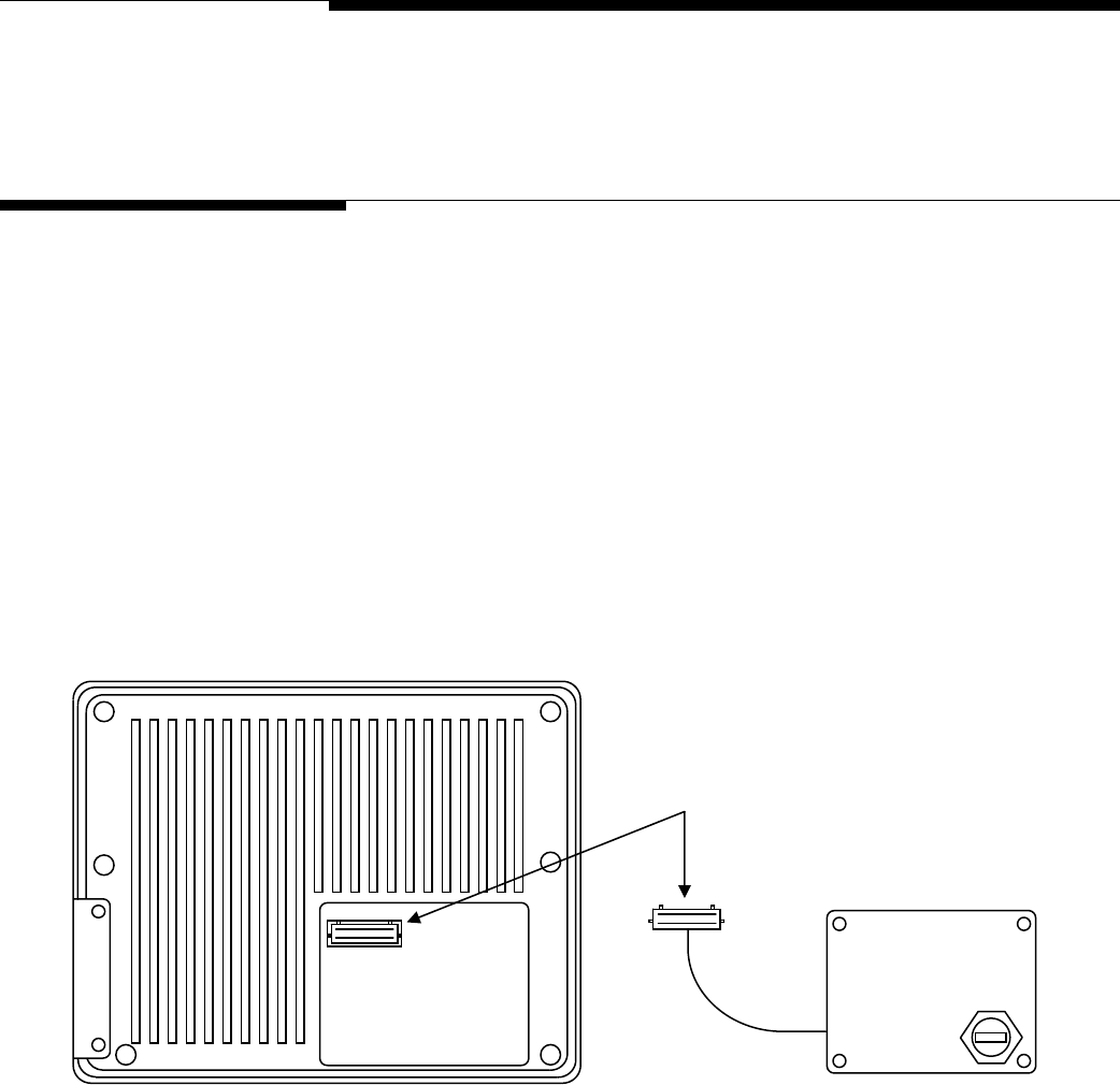
Chapter 9: Forklift Scale Options
USB Port
9
Forklift Scale Options
USB Port
The Universal Serial Bus (USB) port allows you to connect the scale controller to another
device so that you can download data from or upload data to the controller. METTLER
TOLEDO supplies a USB assembly (plastic cover with built-in USB port). Use the
following procedure to install the USB assembly:
1.
Use a screwdriver to remove the access cover in the lower right-hand corner of the
rear of the scale controller.
2.
Plug the 30-pin connector wired to the USB assembly into the 30-pin connector on
the main PCB inside the scale controller (see Figure 9-1). The connectors are keyed
to prevent them from being installed incorrectly. Make sure that the keys are aligned
correctly when you plug the connectors together.
3.
Position the USB assembly over the opening in the rear of the scale controller, and
secure it with the screws that were supplied with the assembly.
30-pin Connector
Scale Controller USB Assembly
Figure 9-1: USB Assembly Installation
(3/05) 9-1
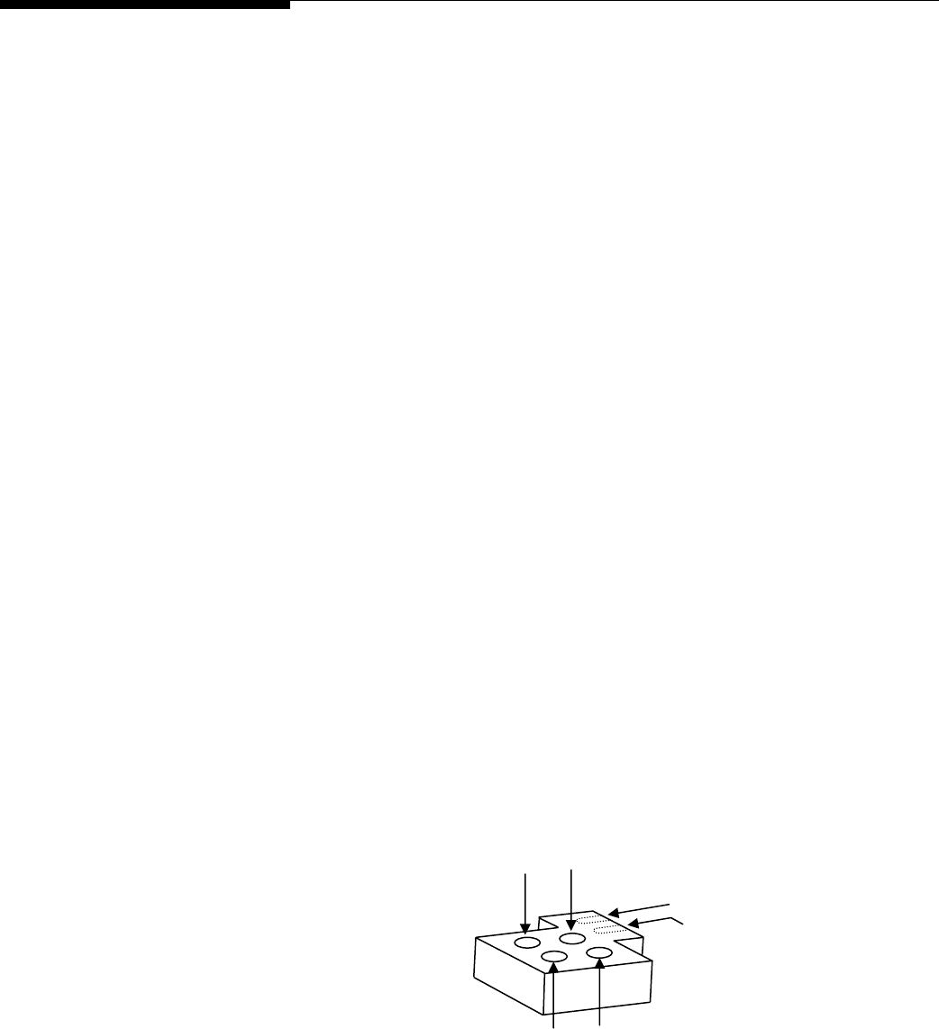
METTLER TOLEDO MCFA Forklift Scale Service Manual
Side Shifter Kit
The forklift scale can be used with an optional side shifter. After installing the scale
carriage on the forklift, install the side shifter and all related components according to
the manufacturer’s instructions. METTLER TOLEDO supplies the following components to
connect the side shifter to the scale: block manifold, bolt, roll pin, four hoses, one hose
strap, and two half covers. Side shifter kits are available for installation on the right or
left side of the scale (right and left are from the perspective of the forklift truck driver).
The figures in this section show a right-side kit. A left-side kit is installed as a mirror
image of a right-side kit.
Side Shifter Kit Installation (Simplex Version)
1.
Remove the cover plate from the underside of the top of the scale carriage. Use the
screws and washers to install the two half cover plates that are supplied with the
side shifter kit. Keep the remaining screws and washers to install the hose strap
later.
2.
Remove the plastic caps from the block manifold and hoses.
3.
Connect the male ends of the hoses to the threaded holes in the block manifold as
shown in Figure 9-2. Use a wrench to tighten the connections so that they are
snug.
4.
Insert the roll pin in the small hole in the block manifold.
5.
Align the roll pin and bolt hole in the block manifold with the mounting holes in the
scale carriage. Bolt the block manifold to the scale carriage. To install the manifold,
you might need to remove the battery cradle temporarily (or the telemetry enclosure
for a left-side kit).
6.
Route the two long hoses over the pulley that is attached to the underside of the top
of the mast. Connect the flare fittings on the hoses to the two pipes that are
mounted on the mast.
7.
Route the two short hoses through the open area in the scale carriage where the
cover plate was removed. Install the hose strap to hold the short hoses in place.
8.
Connect the flare fittings on the short hoses to the piping connections on the side
shifter’s hydraulic cylinder.
Figure 9-2: Block Manifold Installation
Bolt
Connect Short Hoses
Roller Pin
Connect Long Hoses
(3/05)
9-2
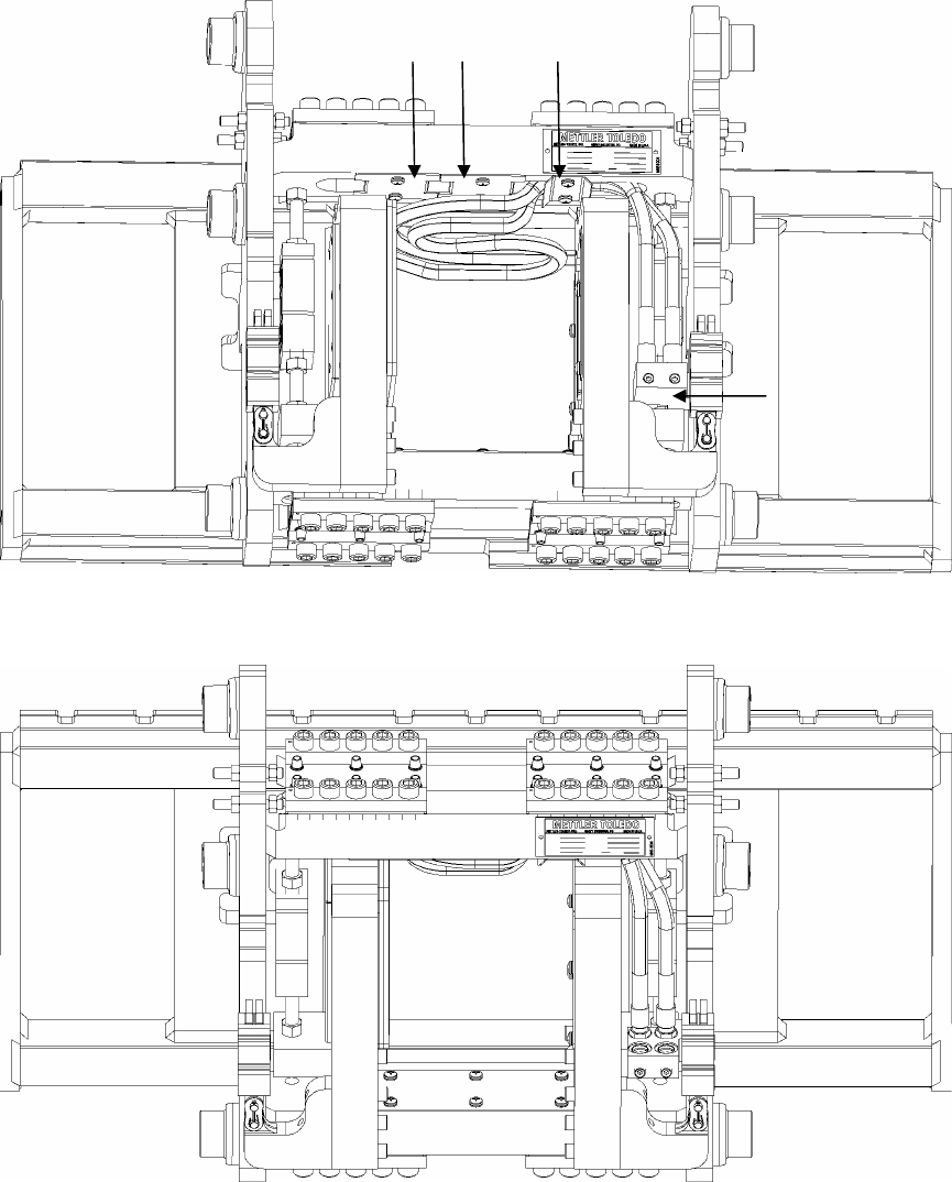
Chapter 9: Forklift Scale Options
Side Shifter Kit
Half Cover Plates Hose Strap
Block Manifold
Figure 9-3: Side Shifter Kit Installation
(3/05) 9-3

Chapter 10: Appendix
Geo Index
10
Appendix
Geo Index
The scale controller can compensate for variations caused by gravitational forces. The
geo index for the location where the scale is calibrated is programmed into the scale
controller at the factory. When the scale is moved to a new location, the geo index for
the new location should be entered in scale setup. Use the following table to determine
the geo index for a location. Refer to Chapter 4 for information about entering a geo
index.
Northern
and
Height above sea level in meters
southern
latitude
0
325
325
650
650
975
975
1300
1300
1625
1625
1950
1950
2275
2275
2600
2600
2925
2925
3250
3250
3575
in Height above sea level in feet
degrees and minutes 0
1060
1060
2130
2130
3200
3200
4260
4260
5330
5330
6400
6400
7460
7460
8530
8530
9600
9600
10660
10660
11730
0° 0′ —5° 46′ 5 4 4 3 3 2 2 1 1 0 0
5° 46′ — 9° 52′ 5 5 4 4 3 3 2 2 1 1 0
9° 52′ — 12° 44′ 6 5 5 4 4 3 3 2 2 1 1
12° 44′ — 15° 6′ 6 6 5 5 4 4 3 3 2 2 1
15° 6′ — 17° 10′ 7 6 6 5 5 4 4 3 3 2 2
17° 10′ — 19° 2′ 7 7 6 6 5 5 4 4 3 3 2
19° 2′ — 20° 45′ 8 7 7 6 6 5 5 4 4 3 3
20° 45′ — 22° 22′ 8 8 7 7 6 6 5 5 4 4 3
22° 22′ — 23° 54′ 9 8 8 7 7 6 6 5 5 4 4
23° 54′ — 25° 21′ 9 9 8 8 7 7 6 6 5 5 4
25° 21′ — 26° 45′ 10 9 9 8 8 7 7 6 6 5 5
26° 45′ — 28° 6′ 10 10 9 9 8 8 7 7 6 6 5
28° 6′ — 29° 25′ 11 10 10 9 9 8 8 7 7 6 6
29° 25′ — 30° 41′ 11 11 10 10 9 9 8 8 7 7 6
30° 41′ — 31° 56′ 12 11 11 10 10 9 9 8 8 7 7
31° 56′ — 33° 9′ 12 12 11 11 10 10 9 9 8 8 7
33° 9′ — 34° 21′ 13 12 12 11 11 10 10 9 9 8 8
34° 21′ — 35° 31′ 13 13 12 12 11 11 10 10 9 9 8
35° 31′ — 36° 41′ 14 13 13 12 12 11 11 10 10 9 9
36° 41′ — 37° 50′ 14 14 13 13 12 12 11 11 10 10 9
37° 50′ — 38° 58′ 15 14 14 13 13 12 12 11 11 10 10
38° 58′ — 40° 5′ 15 15 14 14 13 13 12 12 11 11 10
40° 5′ — 41° 12′ 16 15 15 14 14 13 13 12 12 11 11
41° 12′ — 42° 19′ 16 16 15 15 14 14 13 13 12 12 11
42° 19′ — 43° 26′ 17 16 16 15 15 14 14 13 13 12 12
(3/05) 10-1

METTLER TOLEDO MCFA Forklift Scale Service Manual
Northern
and
Height above sea level in meters
southern
latitude
0
325
325
650
650
975
975
1300
1300
1625
1625
1950
1950
2275
2275
2600
2600
2925
2925
3250
3250
3575
in Height above sea level in feet
degrees and minutes 0
1060
1060
2130
2130
3200
3200
4260
4260
5330
5330
6400
6400
7460
7460
8530
8530
9600
9600
10660
10660
11730
43° 26′ — 44° 32′ 17 17 16 16 15 15 14 14 13 13 12
44° 32′ — 45° 38′ 18 17 17 16 16 15 15 14 14 13 13
45° 38′ — 46° 45′ 18 18 17 17 16 16 15 15 14 14 13
46° 45′ — 47° 51′ 19 18 18 17 17 16 16 15 15 14 14
47° 51′ — 48° 58′ 19 19 18 18 17 17 16 16 15 15 14
48° 58′ — 50° 6′ 20 19 19 18 18 17 17 16 16 15 15
50° 6′ — 51° 13′ 20 20 19 19 18 18 17 17 16 16 15
51° 13′ — 52° 22′ 21 20 20 19 19 18 18 17 17 16 16
52° 22′ — 53° 31′ 21 21 20 20 19 19 18 18 17 17 16
53° 31′ — 54° 41′ 22 21 21 20 20 19 19 18 18 17 17
54° 41′ — 55° 52′ 22 22 21 21 20 20 19 19 18 18 17
55° 52′ — 57° 4′ 23 22 22 21 21 20 20 19 19 18 18
57° 4′ — 58° 17′ 23 23 22 22 21 21 20 20 19 19 18
58° 17′ — 59° 32′ 24 23 23 22 22 21 21 20 20 19 19
59° 32′ — 60° 49′ 24 24 23 23 22 22 21 21 20 20 19
60° 49′ — 62° 9′ 25 24 24 23 23 22 22 21 21 20 20
62° 9′ — 63° 30′ 25 25 24 24 23 23 22 22 21 21 20
63° 30′ — 64° 55′ 26 25 25 24 24 23 23 22 22 21 21
64° 55′ — 66° 24′ 26 26 25 25 24 24 23 23 22 22 21
66° 24′ — 67° 57′ 27 26 26 25 25 24 24 23 23 22 22
67° 57′ — 69° 35′ 27 27 26 26 25 25 24 24 23 23 22
69° 35′ — 71° 21′ 28 27 27 26 26 25 25 24 24 23 23
71° 21′ — 73° 16′ 28 28 27 27 26 26 25 25 24 24 23
73° 16′ — 75° 24′ 29 28 28 27 27 26 26 25 25 24 24
75° 24′ — 77° 52′ 29 29 28 28 27 27 26 26 25 25 24
77° 52′ — 80° 56′ 30 29 29 28 28 27 27 26 26 25 25
80° 56′ — 85° 45′ 30 30 29 29 28 28 27 27 26 26 25
85° 45′ — 90° 00′ 31 30 30 29 29 28 28 27 27 26 26
(3/05)
10-2

METTLER TOLEDO
Publication Suggestion Report
If you have suggestions concerning this publication, please complete this form and fax it to (614) 841-7295
Publication Name: METTLER TOLEDO MCFA Forklift Scale Service Manual
Publication Part Number: A17082300A Publication Date: 3/05
PROBLEM(S) TYPE: DESCRIBE PROBLEM(S): INTERNAL USE ONLY
Technical Accuracy Text Illustration
Completeness Procedure/step Illustration Definition
Info. in manual
What information is missing? Example Guideline Feature
Explanation Other (please explain below)
Info. not in manual
Clarity
What is not clear?
Sequence
What is not in the right order?
Other Comments
Use another sheet for
additional comments.
Your Name: Location:
Phone Number: ( )
Mettler-Toledo, Inc. Printed in USA 14981600A
Fax this completed form to METTLER TOLEDO at (614) 841-7295

METTLER TOLEDO
1900 Polaris Parkway
Columbus, Ohio 43240 USA
P/N: A17082300A
(3/05).00
METTLER TOLEDO® is a registered trademark of Mettler-Toledo, Inc.
© 2005 Mettler-Toledo, Inc.
Printed in USA
A17082400A