Mettler Toledo MULTIRFID5X Multi-RFID-Switch 5x User Manual Guidance for Module manufacturer V2 0
Mettler-Toledo GmbH Multi-RFID-Switch 5x Guidance for Module manufacturer V2 0
InstallationInstructions

METTLER TOLEDO
11.11.2016, mme Ver.1.0
Installation Instructions
THVQCB & THVMULTIRFID5X
General Information
Changes or modifications made to the equipment not expressly approved by METTLER TOLEDO may
void the FCC / IC authorization to operate this equipment.
The use of the transceiver module is authorized in mobile or fixed host devices taking into account the
conditions listed below:
• OEM Integrator must ensure that the end user manual may not contain any information about
the way to install or remove the module from the final product.
• Depending on the final host device additional authorization requirements for the non-
transmitter functions of the transmitter module may be required (i.e., Verification, or
Declaration of Conformity) The OEM integrator is responsible for ensuring that after the
module is installed and operational the host continues to be compliant with the Part 15B
unintentional radiator requirements.
• The information on the label and in the user manual is required to be incorporated in the user
manual of the final host. see 47 CFR15 requirements for more details (e.g. 15.19 / 15.21 /
15.101 / 15.105 / RSS-GEN / ICES)
• Additional label with the words ‘Contains FCC ID: THVQCB / Contains FCC ID:
THVMULTIRFID5X’ shall be applied and visible from the outside of the host product.
• The module must be installed and used in strict accordance with the manufacturer’s
instructions as described in the user documentation that comes with the module.
• The end user manual for the final host product operating with this transmitter must include
operating instructions to satisfy RF exposure compliance requirements.
e.g
Radiofrequency radiation exposure Information:
This equipment complies with FCC radiation exposure limits set forth for an uncontrolled
environment. This equipment should be installed and operated with minimum distance of 20
cm between the radiator and your body.
This transmitter must not be co-located or operating in conjunction with any other antenna or
transmitter.
• Only the antennas approved by METTLER TOLEDO must be used. The antennas may not be
modified. The antenna must not be co-located or operating in conjunction with any other
antenna or transmitter. No additional antenna must be used.
• When the final host product operating with this transmitter deviate from above, installation of
this module into specific final hosts may require the submission of a Class II permissive
change application containing data pertinent to RF Exposure, spurious emissions, ERP/EIRP,
and host/module authentication, or new application if appropriate.
Feel free to contact us if additional guidance is required.
Mettler-Toledo GmbH
Laboratory Weighing
Research & Development
Im Langacher 44
8606 Greifensee
Switzerland
http://www.mt.com
METTLER TOLEDO
11.11.2016, mme Ver.1.0
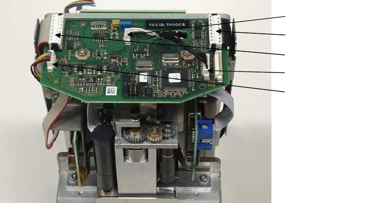
Installation of THVQCB
The image below shows how the PCB is assembled to the dosing unit.
The PCB is attached with two M3x5 TORX screws.
The RFID antenna cable is pluged in as shown in the image.
RFID Antenna
Cable
Motor Controler 1
Cable
Motor Controler 2
Cable
Mini-z Cable
CAN Cable
METTLER TOLEDO
11.11.2016, mme Ver.1.0
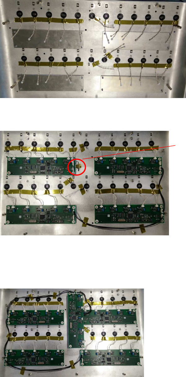
Installation of THVMULTIRFID5X
1. Tie all wires down with Kapton tape, as shown below.
2. Mount 4 PCBs and plug coils into PCBs.
3. Plug termination resistor into marked PCB and tie down with Kapton tape.
4. Plug PicoBlade cables as shown below, and tie down with Kapton tape.
5. Plug short PicoBlade cable into connector next to termination resistor.
6. Mount plate and PCB in the middle.
7. Plug coils into PCB.
8. Plug remaining PicoBlade cables in and tie them down with Kapton tape, as shown
below.
Termination resistor