Meyer Sound Loudspeaker Msl 10A Users Manual
MSL-10A to the manual 1528d811-32d9-4733-9d0b-1372cf0395fb
2015-02-09
: Meyer-Sound Meyer-Sound-Loudspeaker-Msl-10A-Users-Manual-555601 meyer-sound-loudspeaker-msl-10a-users-manual-555601 meyer-sound pdf
Open the PDF directly: View PDF ![]() .
.
Page Count: 8
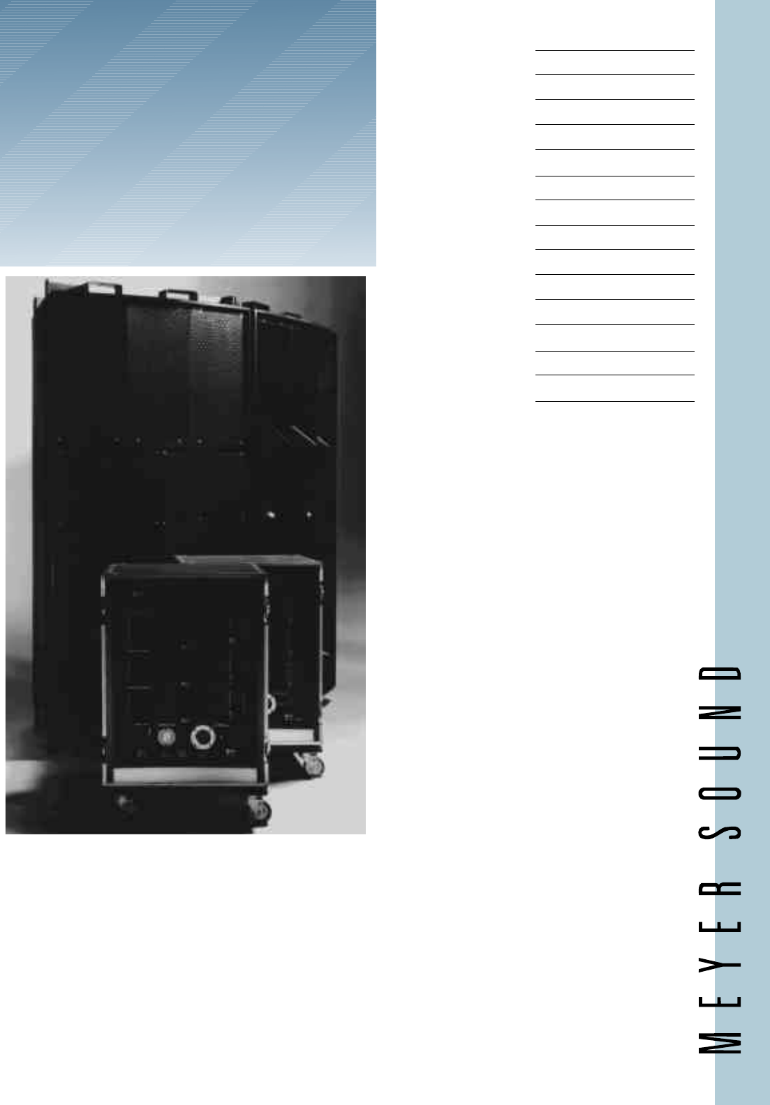
MSL-10A
High Power
Loudspeaker
System
The Meyer Sound MSL-10A is an
extremely high-power, high-performance
loudspeaker system designed for large-scale
music reinforcement and public address
applications.
The MSL-10A System comprises an all-
horn, integral full-range loudspeaker
cabinet constructed as a 30-degree
arrayable section, and a 19" electronics
rack (on wheels) housing the M-10A
Control Electronics Unit, three MS 10
Power Amplifiers and an Interface Unit.
The minimum standard MSL-10A
configuration comprises two loudspeaker
cabinets, each with its own electronics
rack. Additional MSL-10A cabinets may be
employed as modular 30-degree building
blocks to increase the coverage and
acoustical power of the system, providing
extensive flexibility to meet specific
application requirements.
Features
Extremely High Power
Exceptional Clarity
Point Source Arraying
Weatherproof Hardware
Long-Term Reliability
Applications
Paging and Announcing
Outdoor Sports Arenas
Stadiums
Racetracks
Large-Scale Touring
Concert Reinforcement
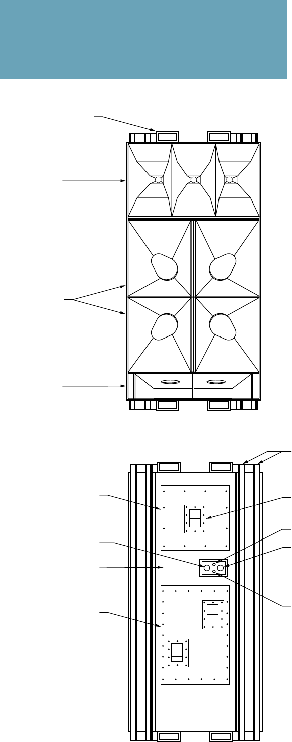
MSL-10A Loudspeaker
Fork lift brackets
(top & bottom)
High frequency
horns
Low frequency
horns
Reflex port and
enclosure
ventilation
Front View
High frequency
driver service
access
Speaker
connector
Serial number
plate
Low frequency
driver service
access
Rigging
points
Hatch handle
Environmental power
indicator
Environmental power
connector
Environmental circuit
breaker
Rear View
Enclosure Features:
• High Q maximizes
reverberation control
• Modular, arrayable design
for predictable, coherent
coverage
• High acoustical output
with low distortion
• Rugged construction
• Internal environmental
heating/cooling system
• Extensive weatherproofing
for long-term reliability
• Stainless steel hardware
throughout
• Rigged for transportation
and installation

Acoustical System1
Frequency Response2
Maximum SPL at 100 feet
Continuous
Peak
HF Coverage, -6 dB points
Horizontal
Vertical
MSL-10A Loudspeaker (one 30° section)
Driver Complement
HF DC Protection
Enclosure
Finish
Protective Grill
Rigging
Dimensions
Weight
Power Requirement
Connectors
Notes:
1. Acoustical specifications
are given for the minimum
configuration of two 30°
sections.
2. Measured 100 feet on axis,
half-space conditions,
pink noise input, in third-
octave bands.
70 Hz - 16 kHz ±4 dB
110 dB
120 dB
60 degrees
40 degrees
(4) MS-12 12-inch cone drivers
(3) MS-2001 2-inch horn drivers
50 µf polypropylene capacitor
Vented, horn-loaded, 12-ply hardwood
Weatherproof black coating
Three-piece expanded metal screen, damped
Eight points, 3/4 inch rigging holes in steel cradle
41" W x 85" H x 35" D
700 lbs (318 kg)
200–240 VAC, 3A (heater and fan supply)
Pyle with weather cap, heavy-duty AC in, weather
protected
The MSL-10A Loudspeaker cabinet is
fortified for long-term reliability in outdoor
installations, and is thoroughly inspected at
several stages during assembly. Con-
structed of high-grade Finnish birch
hardwood, the enclosure is resin-impreg-
nated in critical areas, bonded with
structural epoxy adhesive, and coated with
a finish that tolerates cabinet swelling
without cracking. Thermostatically-
controlled environmental heating and
cooling systems, which receive power from
the MSL-10A Rack, ventilate the cabinet
and stabilize its interior temperature.
The MSL-10A cabinet is internally
damped and braced for maximum energy
transfer and highly intelligible reproduc-
tion of voice and music — which is
especially important in acoustically difficult
environments. Internal and external steel
bracing and integral all-steel rigging points
ensure safe, efficient installation, and
integral forklift brackets ease handling.
Component Quality and Linearity
The MSL-10A Loudspeaker employs
driver components whose design, construc-
tion, and testing have been proven in over a
decade of demanding professional use. The
transducer magnetic circuits and suspen-
sions have been optimized for maximum
linearity, resulting in extremely low
harmonic distortion and consistent sonic
accuracy at all dynamic levels. Ferrofluid
cooling and back-vented gaps and pole
pieces maximize power handling, and
water-resistant treatment of all driver
elements ensures greatest reliability in
outdoor installations. Gold-plated contacts
and stainless steel mounting hardware
resist corrosion.
Rigorous Testing
The M-10A Control Electronics and
MSL-10A Loudspeaker components are
individually and fully tested at several
stages of manufacture to ensure maximum
reliability and minimum component
failure.
Each driver is subject to an eight-hour
dynamic burn-in to test for power handling
and peak excursion performance, and
thorough computer-based testing prior to
shipment ensures optimal system operation
upon installation.
Finally, the MSL-10A System has
undergone years of field testing in stadium
installations and touring reinforcement,
resulting in a mature, refined technology
that offers unmatched performance.
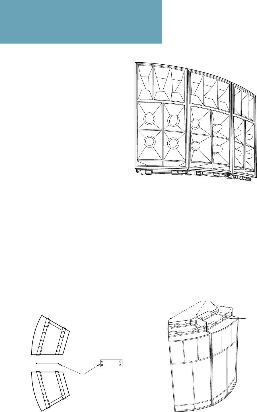
Arraying and Rigging
The MSL-10A loudspeaker is
designed to function as a modular
building block capable of being
arrayed in multiples to satisfy a wide
range of acoustical power and
coverage requirements.
Configured as a tightly controlled
30-degree section, the MSL-10A
cabinet features a trapezoidal con-
struction which forms curved arrays.
MSL-10A’s in an array combine
acoustically in a seamless fashion to
form a radiating arc, producing
uniform, coherent wavefronts over
the angle subtended by the array.
The propagation characteristic of
an MSL-10A array thereby closely
approximates that of a theoretically
perfect pulsating gas sphere — but
rather than being omnidirectional,
the radiation is confined to an area
that is controlled by the array con-
figuration. This yields exceptional
intelligibility in reverberant environ-
ments, with substantially the same
sonic character in both the near and
far field – a critical advantage in large-
scale sound reinforcement.
To expedite arraying and installa-
tion, the MSL-10A is fitted with an
integral rigging system. Comprising
steel braces on the cabinet sides and
convenient fork lift feet on top and
bottom, the rigging system eases
handling and provides secure points
from which to suspend the cabinet. In
A Two-Section Array Showing Locations
of Hanging Points
Do Not Lift
or Hang by
Upper Fork
Lift Feet
Rig From Spacer/Hanger Bar
Installation of Spacer/One-Piece
Hanger Bar
Spacer/Hanger Bar
Left: Top View
Right: Side View
Three-Section Array
40° Vertical Coverage
90° Horizontal Coverage
conjunction with an accessory spacer/
hanger bar, it also facilitates coupling
adjacent cabinets to form rigid arrays.
Wide Horizontal Arrays
The minimum MSL-10A configura-
tion is two cabinets (as shown below).
Coupled side-by-side, this configu-
ration delivers 60 degrees horizontal
coverage. Spacer/hanger bars and
case-hardened steel bolts join the
cabinets together and provide rigging
points for hoisting.
To increase the horizontal cover-
age of the array, one or more cabinets
may be added as shown in the
illustration above. Each cabinet added
to the array extends its horizontal
coverage by 30 degrees while main-
taining a consistent 40 degrees of
vertical coverage.
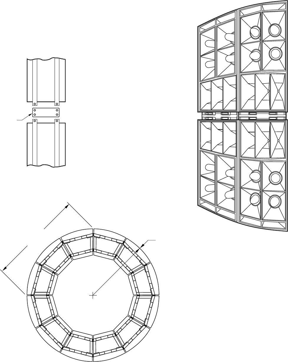
Long-Throw Configuration
20° Vertical Coverage
60° Horizontal Coverage
Ring Configuration
360° Horizontal Coverage
113"
(approx.) 80.25" radius
(approx.)
Use of Spacer/Hanger Bar to Couple
Cabinets Vertically
Spacer/
Hanger
Bar
Long-Throw Arrays
To increase the effective throw of
the system, MSL-10A cabinets may be
arrayed one atop another with high
horns together, as shown in the
illustration at the right. Spacer/
hanger bars are used to couple the
cabinets both horizontally and
vertically, as illustrated at the left. A
second set of spacer/hanger bars at
the top provides convenient points for
hoisting and hanging the array.
In this configuration, coupling
between the adjacent horns narrows
the vertical dispersion of the array to
±10 degrees, moving the focal point
(or virtual source) farther behind the
array. Since inverse-square propaga-
tion losses depend upon the distance
from the focal point (rather than from
the array surface), this configuration
maintains high sound pressures over
very long distances.
The effect is analogous to the
difference between a floodlight and a
searchlight. The floodlight distributes
energy very widely, as though from a
proximate point source, and its
intensity decreases relatively quickly
with increased distance. The search-
light, on the other hand, projects a
narrow, focused beam which is the
equivalent of colimated light from a
distant, very powerful point source.
Its intensity therefore decreases much
more slowly with increased distance.
Ring Configuration
As shown at left, twelve MSL-10A
cabinets arrayed horizontally form a
complete ring providing 360-degree
horizontal coverage.
This system produces prodigious
sound pressures in a reasonably
compact package (80.25" radius), and
is effective for large scale concerts in-
the-round or sporting events in very
large stadiums. Where required,
additional cabinets may be added
vertically, as shown above, to increase
the throw for any portion(s) of the
total arc.
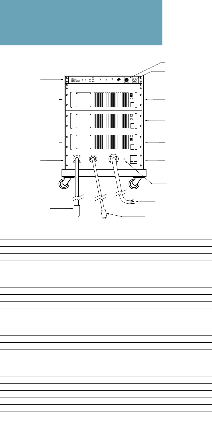
MSL-10A Rack System
M-10A Control
Electronics Unit
High Amplifier
50A Power Switch/
Circuit Breaker
Low Amplifier 1
Low Amplifier 2
MS 10 Power
Amplifiers
Notes:
1. Cycle consisting of
50 msec sinewave at 120 V
peak and 450 msec
sinewave at 24 V peak
2. Cycle consisting of
25 msec sinewave at 120 V
peak and 975 msec
sinewave at 41 V peak
3. Cycle consisting of
400 msec sinewave at
120 V peak and 2400 msec
interval at 0 V
I/O Panel
Power Indicator
Rack System Features:
• Integrated signal process-
ing includes optimized
active crossover, ampli-
tude and phase correc-
tion, and driver protection
circuitry to maintain safe
operating levels
• Modular amplifier rack
includes control electron-
ics, amplifiers and
interconnection panel for
easy interface with
speaker system
• Input/Output unit provides
power switch and circuit
breaker for entire system;
protection and power
distribution to the CEU,
amplifiers, and loud-
speaker; and loudspeaker
and external power
connections
• Completely engineered
and ready to install
Mains Power Cable
Environmental Power Cable
Loudspeaker Cable
M-10A Control Electronics Unit
(3) MS 10 Power Amplifiers
I/O Panel
24" W x 36 1/4" H x 27 3/4" D
10 ga. 6 cond., Pyle ZPEK 1620 both ends
16 ga. 3 cond., NEMA L6-15R both ends
8 ga. 3 cond., Hubbell CS-8264-C to bare leads
Bridge mode, single balanced input
16 dB
1800 watts
1100 watts
367 watts
In bridged mode, 4 ohm resistive load, will
reproduce three specified burst waveforms1,2,3,
each continuously for 1 hour, without shutdown or
limiting
In bridged mode, 8 ohm resistive load, passes the
FTC continuous power test
In bridged mode, 4 ohm resistive load, will
reproduce a 400 msec sinewave burst at 225
watts, 2.8 sec burst interval, continuously for
1 hour without shutdown or limiting
Latch-up protection
Indicators for clipping, limiting, thermal overload
MSL-10A Rack System (each section)
Component Complement
Dimensions
Interconnects
100' Speaker Cable
100' Environmental AC Cable
30' Mains Power Cord
MS 10 Power Amplifier
Configuration
Voltage Gain
Power Output
0.5 sec burst @ 4 ohms
FTC Rating @ 8 ohms
Continuous @ 8 ohms
Nominal (235 VAC) Mains Operation
High (255 VAC) Mains Operation
Low (200 VAC) Mains Operation
General
Loop Output
Signal Input

Active balanced, 10k ohms, ISO™ Input
Active push-pull, 600 ohm drive
+20 dBv
+26 dBv
-90 dBv (“A” weighted)
120 dB
800 Hz
RMS, peak and excursion limiters
RMS, peak and excursion limiters
Peak limiter
Power/Ready LED
High and Low Sense LED’s
VHF, HF and LF Limit LED’s
Safe LED
Standby/On switch
VHF Cal/Music switch
Safe/AutoSafe switch
Input Attenuation (calibrated in dB)
3-pin XLR-type female, front panel mounted
3-pin XLR-type male, front panel mounted
3-pin XLR-type male, rear panel mounted
Dual banana receptacles, rear panel mounted
M-10A Control Electronics Unit
Input Type
Output Type
Maximum Input/Output Level
Unbalanced
Balanced
Hum and Noise
Dynamic Range
Electronic Crossover Frequency
Driver Protection Circuits
Low Frequency
High Frequency
VHF
Indicators
Controls
Connectors
Input
Loop Out
Hi and Lo Output
Sense
Power Requirement
Mains AC Voltage Source
Maximum Power Consumption
Maximum Continuous RMS Current1
Peak Instantaneous Operating Current2
Peak Inrush (Turn-On) Current3
Cold
Hot
Idle Current4
200 – 260 VAC, 50 A, 50/60 Hz
8700 VA
38 A rms (Power factor ≈ .93 lagging)
94 A peak
240 A peak
360 A peak
9 A rms
Notes:
1. Current waveform is non-
sinusoidal, so the RMS
current rating applies only
to power consumption
and heating from the
source. The peak current
rating must be considered
when determining I2R
losses in power cable.
Peak losses will lower the
internal power supply
voltages linearly.
2. One AC cycle.
3. Inrush current due to
magnetization, <40 ms ␣␣␣
(2 cycles).
4. Environmental heaters on.
AC Interfacing and Protection
The MSL-10A Rack System requires a
single-phase AC voltage source wired
between the øX and øY terminals of the
Rack System AC inlet, with earth ground as
a chassis safety connection. It may be
interfaced to virtually any delta or wye
source configuration, with the Rack øX and
øY connected to any two source terminals
that yield 200~260 VAC; multiple racks
may be connected to different phases of a
polyphase source to distribute the load. The
maximum safe isolation voltage between
øX or øY and earth is 480 VAC.
The AC inlet is protected with a 50 A,
250 V switch-type magnetic circuit breaker
which is CSA, VDE and UL approved (UL
Code “A”) and is located on the front of the
I/O Panel. Power distribution to each
amplifier is individually protected with a
two-pole, 20 A, 250 V switch-type breaker
located on the rear panel. The environmen-
tal power and M-10A CEU share a single 20
A, 250 V breaker, also located on the rear
panel.

Meyer Sound Laboratories, Inc.
2832 San Pablo Avenue
Berkeley, CA 94702
(
510
) 486-1166
FAX (
510
) 486-8356
Sound
engineering
for the art
and science
of sound.
© 1990 Meyer Sound 04.110.099.01B
Meyer Sound Laboratories has
devoted itself to designing,
manufacturing, and refining com-
ponents that deliver superb sonic
reproduction. Every part of every
component is designed and built to
exacting specifications and
undergoes rigorous, comprehensive
testing in the laboratories.
Research remains an integral,
driving force behind all production.
Meyer strives for sound quality that
is predictable and neutral over an
extended lifetime and across an
extended range.
