Mge Ups Systems 30A Users Manual 1NOT113F
30A to the manual 00dbb986-4217-42c8-9d4c-82fe0da40425
2015-02-09
: Mge-Ups-Systems Mge-Ups-Systems-30A-Users-Manual-555644 mge-ups-systems-30a-users-manual-555644 mge-ups-systems pdf
Open the PDF directly: View PDF ![]() .
.
Page Count: 30
34020113EN/AA - Page 1
Galaxy 3000
10 - 30 kVA
LE SAVOIR FAIRE MERLIN GERIN
MGE UPS SYSTEMS
Installation and user
manual
www.mgeups.com
Upsilon STS
30A-60A-100A-160A
250A-400A-600A
T
H
E
U
N
I
N
T
ER
R
U
P
T
I
B
L
E
P
O
W
E
R
P
RO
V
I
D
E
R
Page 2 - 34020113EN/AA
34020113EN/AA - Page 3
Introduction
Thank you for selecting an MGE UPS SYSTEMS product to protect your electrical equipment.
The Upsilon STS range has been designed with the upmost care. We recommend that you take the time to read this
manual to take full advantage of the many features of your new equipment.
MGE UPS SYSTEMS pays great attention to the environmental impact of its products. Measures that have made Upsilon
STS a reference in environmental protection include:
◗ the eco-design approach used in product development,
◗ production on an industrial site certified ISO 14001,
◗ recycling of Upsilon STS at the end of its service life.
To discover the entire range of MGE UPS SYSTEMS products and the options available for the Upsilon STS range, we
invite you to visit our web site at www.mgeups.com or contact your MGE UPS SYSTEMS representative.
All products in the Upsilon STS range are protected by patents. They implement original technology not available to competitors of MGE
UPS SYSTEMS.
To take into account evolving standards and technology, equipment may be modified without notice. Indications concerning technical
characteristics and dimensions are not binding unless confirmed by MGE UPS SYSTEMS.
This document may be copied only with the written consent of MGE UPS SYSTEMS. Authorised copies must be marked "Upsilon STS
Installation and User Manual, nr 3402011300".
Page 4 - 34020113EN/AA
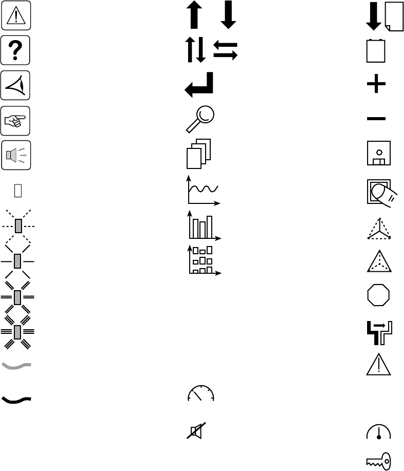
Foreword
Using this document
Important instructions that must
be followed
Information, advice, help
Visual indication
Action
Audio indication
LED off
Up / down selection
Other selection
Confirm
Details
Scrolling menu
Digital display
Return to previous display
Delete
Pictograms
Document
Graphic display
Graphic display
Graphic display
Access to measurements
Information may be found primarily by consulting:
◗ the contents,
◗ the index.
Display
LED on orange
LED on red
Note: LEDs and switches are represented in their rest position. Transient conditions are indicated by dotted arrows.
Earth cables
Other cables
Buzzer off
Go up or down one page
LED flashing
Select date for event log
consultation
Increase
Reduce
Save
Enter characters
Phase-to-neutral
measurements
Phase-to-phase
measurements
Interrupt manual transfer
without break
Transfer
Alarm
Status conditions
Settings
LED on green
Maintenance
88.8
8.88
E
S
C
D
E
L
VOLT
17
mai
STOP
0101
1010
0101
34020113EN/AA - Page 5
Contents
1. Presentation
1.1 Upsilon STS 30 - 60 - 100 - 160 - 250 A (cabinet 1400 mm high) .............................................. 7
1.2 Upsilon STS 30 - 60 - 100 - 160 - 250 - 400 - 600 A (cabinet 1900 mm high) .......................... 7
1.3 Access to control and connections .......................................................................................... 8
Upsilon STS 30 - 60 - 100 - 160 - 250 A (cabinet 1400 mm high) ................................................. 8
Upsilon STS 30 - 60 - 100 - 160 - 250 - 400 - 600 A (cabinet 1900 mm high) ............................... 8
1.4 Man / machine interface ............................................................................................................... 9
1.5 Relay communication card ........................................................................................................ 10
1.6 JBus communication card ......................................................................................................... 10
2. Installation
2.1 Positioning .................................................................................................................................. 11
Upsilon STS 30 - 60 - 100 - 160 - 250 A (cabinet 1400 mm high) ............................................... 11
Upsilon STS 30 - 60 - 100 - 160 - 250 - 400 - 600 A (cabinet 1900 mm high) ............................. 11
2.2 Power connections ..................................................................................................................... 12
Upsilon STS 30 to 250 A with input/output: 3 phases + PEN, ..................................................... 12
Upsilon STS 30 to 250 A with input: 3 phases + PEN, output: 3 phases + PE + Neutral ............ 12
Upsilon STS 30 to 250 A with input: 3 phases + PEN, output: 3 phases + PE ............................ 13
Upsilon STS 30 to 250 A with input/output: 3 phases + PE + Neutral ......................................... 13
Upsilon STS 30 to 250 A with input/output: 3 phases + PE ......................................................... 13
Upsilon STS 400 to 600 A with input/output: 3 phases + PEN .................................................... 14
Upsilon STS 400 to 600 A with input: 3 phases + PEN, output: 3 phases + PE + Neutral .......... 14
Upsilon STS 400 to 600 A with input: 3 phases + PEN, output: 3 phases + PE .......................... 15
Upsilon STS 400 to 600 A with input/output: 3 phases + PE + Neutral ....................................... 15
Upsilon STS 400 to 600 A with input/output: 3 phases + PE ....................................................... 15
Cable running for cables entering through the top of the Upsilon STS 30 to 250 A cabinet ........ 16
2.3 Connection of the emergency power off terminal block ......................................................... 16
2.4 Connection of the communication cards ................................................................................. 17
2.5 Connection of the JBUS communication card......................................................................... 17
2.6 Connection of the relay communication card .......................................................................... 18
3. Operation
3.1 Start-up ........................................................................................................................................ 19
3.2 Shutdown..................................................................................................................................... 19
3.3 Normal mode: operation on preferred source S1 .................................................................... 20
Operation on the preferred source ................................................................................................ 20
Automatic transfer to the alternate source .................................................................................... 20
Manual transfer to the alternate source ........................................................................................ 20
Manual transfer to an out-of-phase alternate source .................................................................... 21
3.4 Display screens........................................................................................................................... 22
3.5 Upsilon STS customization........................................................................................................ 23
3.6 Customization of the relay communication card ..................................................................... 24
4 Maintenance
4.1 Identification of anomalies......................................................................................................... 25
4.2 Transfer to the manual bypass .................................................................................................. 25
5 Environment ..................................................................................................................................... 26
Page 6 - 34020113EN/AA
Contents
6 Appendix
6.1 Technical data ............................................................................................................................. 27
Output currents and voltage.......................................................................................................... 27
Thermal characteristics ................................................................................................................. 27
Noise level .................................................................................................................................... 27
Cable sizes ................................................................................................................................... 27
Recommended protection devices upstream of Upsilon STS ..................................................... 27
Permissible-overload curve........................................................................................................... 27
6.2 Simplified diagrams .................................................................................................................... 28
Upsilon STS simplified diagram ................................................................................................... 28
Simplified diagram of an installation ............................................................................................. 28
6.3 Glossary....................................................................................................................................... 29
6.4 Index............................................................................................................................................. 30
34020113EN/AA - Page 7
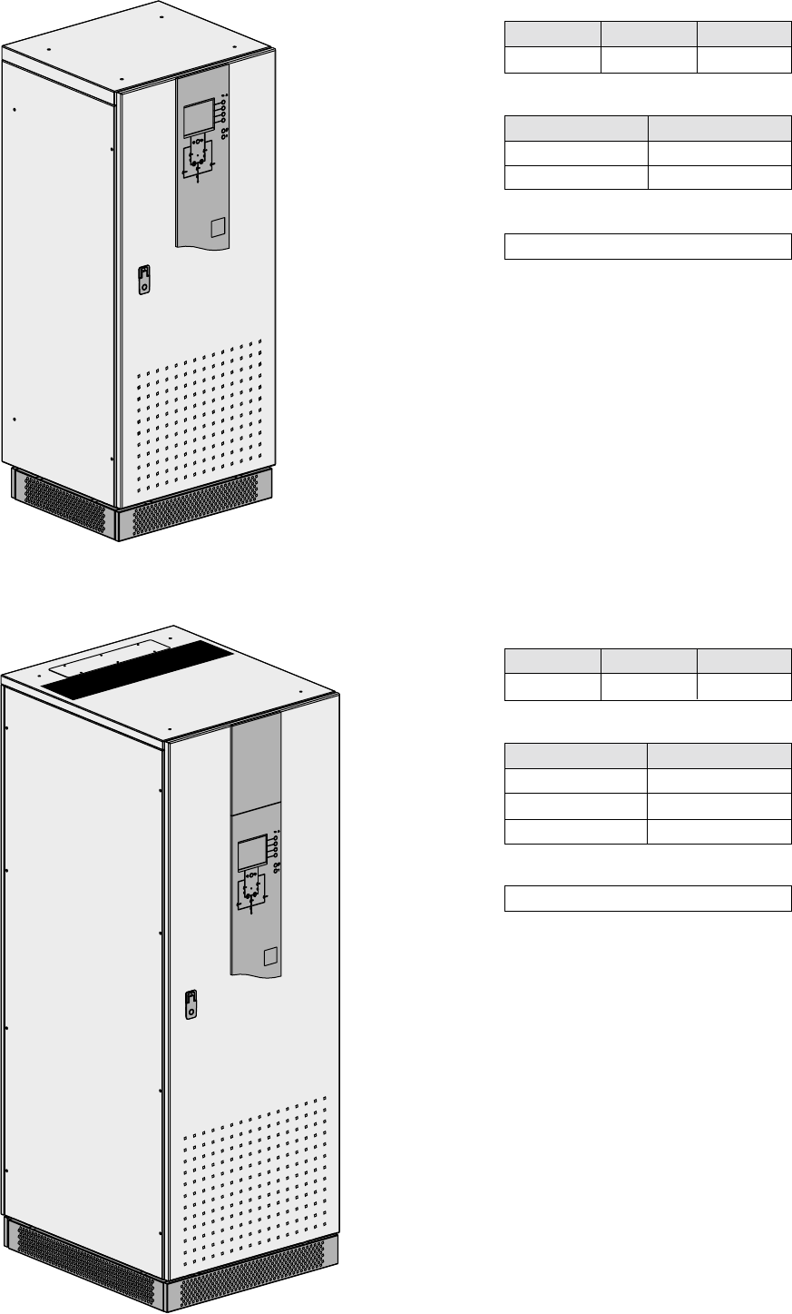
1. Presentation
1.1 Upsilon STS 30 - 60 - 100 - 160 - 250 A (cabinet 1400 mm high)
1.2 Upsilon STS 30 - 60 - 100 - 160 - 250 - 400 - 600 A (cabinet 1900 mm high)
Height
1400
Dimensions in mm
Weight in kg
Width
600
Depth
500
Upsilon STS
30 - 60 - 100 A
160 - 250 A
157 kg
174 kg
Height
1900
Dimensions in mm
Width
715
Depth
800
Weight in kg
Upsilon STS
30 - 60 - 100 A
160 - 250 A
400 - 600 A
215 kg
225 kg
327 kg
Footprint
0.45 m2
Footprint
0.57 m2
Page 8 - 34020113EN/AA
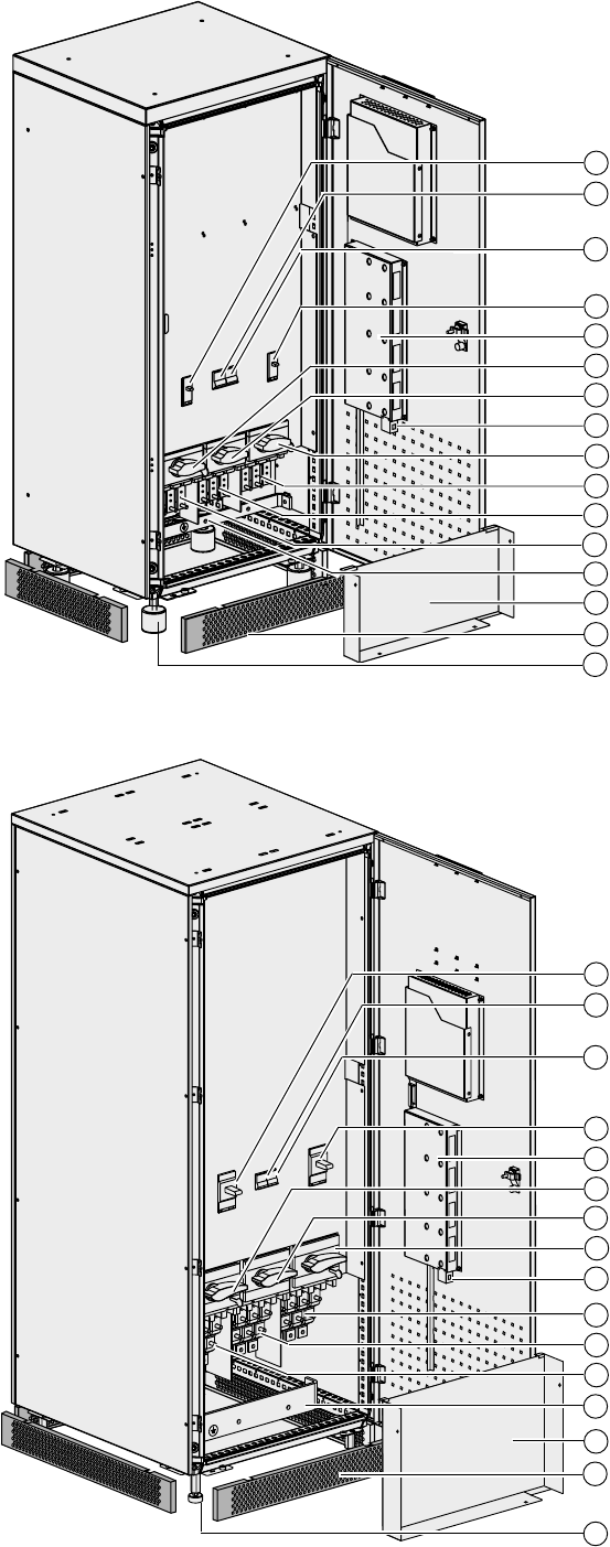
1. Presentation
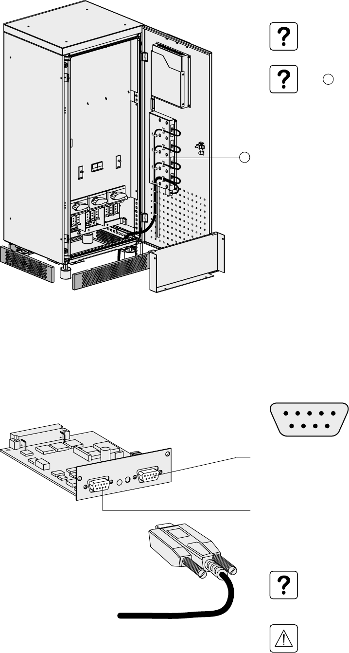
1.3 Access to control and connections
Switch Q1 for Source S1
Circuit breaker Q5 for control electronics
power supply
Circuit breaker Q6 for control electronics
power supply
Switch Q2 for Source S2
Communication card cage
Bypass switch Q1BP for Source S1
Output switch Q3
Bypass switch Q2BP for Source S2
Source S2 connection
Earth bar
Connection cover
Base panels
Circuit breaker Q6 for control electronics
power supply
Switch Q2 for Source S2
Communication card cage
Bypass switch Q1BP for Source S1
Output switch Q3
Bypass switch Q2BP for Source S2
Earth bar
Connection cover
Base panels
Adjustable foot pad
Upsilon STS 30 - 60 - 100 - 160 - 250 A (cabinet 1400 mm high)
Upsilon STS 30 - 60 - 100 - 160 - 250 - 400 - 600 A (cabinet 1900 mm high)
Output connections
Source S1 connection
Source S2 connection
Output connections
Source S1 connection
Adjustable foot pads
Emergency power off terminal block
Switch Q1 for Source S1
Circuit breaker Q5 for control electronics
power supply
Emergency power off terminal block
1
2
3
5
4
6
7
8
9
12
13
14
15
1
2
3
5
4
6
7
8
9
12
13
14
15
10
11
10
11
16
16
34020113EN/AA - Page 9
Q1BP
Q1 Q2
Q2BP
Q3
load
charge
?
Menu
Alarme
Mesures
Etats
Historique
Transfert
Alarme
Mesures
Etats
Historique
Menu
UPS galaxy
deuxième étage, salle 13
UPS galaxy
deuxième étage, salle 14
Source secours
UPS galaxy
deuxième étage, salle 13
Source prioritaire
UPS galaxy
deuxième étage, salle 14
Upsilon STS
NORMAL OPERATION
I1 17 A I2 9 A I3 2 A
1 KW 6 KVA
PF 0.3
preferred
synchro
UPS 1
= 0°
U12 413 V
U23 414 V
U31 414 V
50.0 Hz
UPS 2
U12 412 V
U23 415 V
U31 413 V
50.0 Hz
volt
1. Presentation
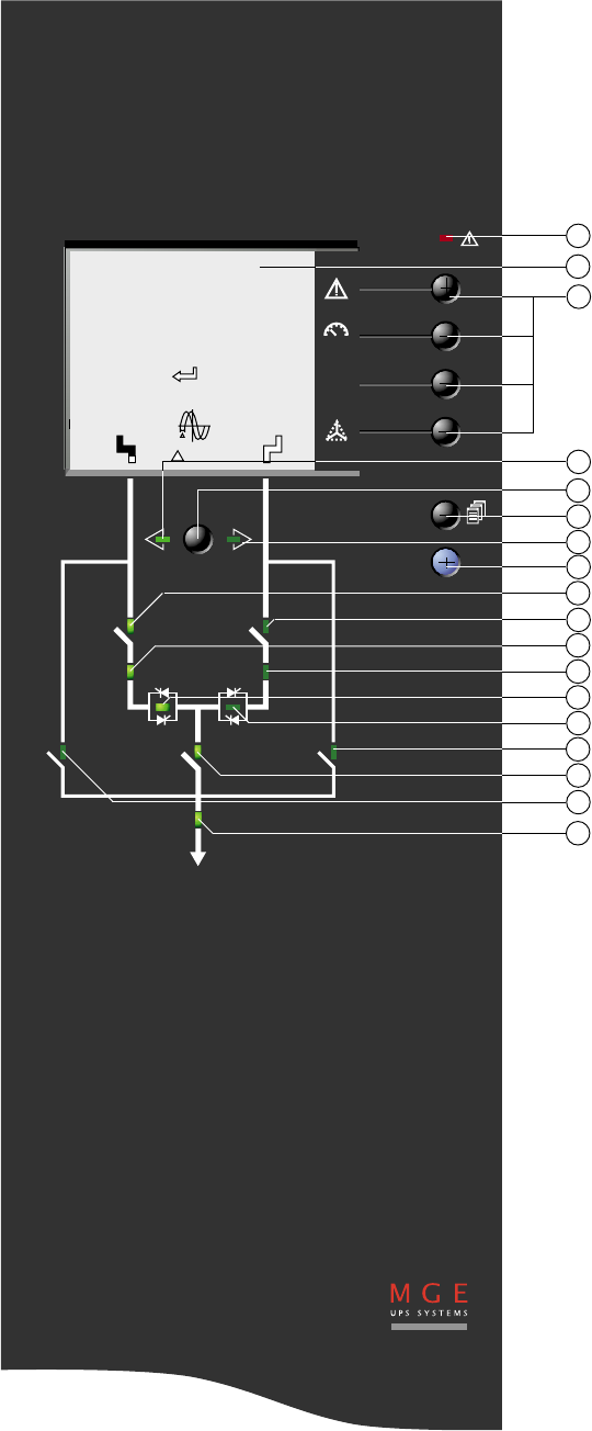
1.4 Man / machine interface
21
22
23
24
26
25
27
28
29
30
31
32
33
34
35
36
37
38
General alarm
Graphic display
Function buttons
Preferred source S1
Manual transfer button
Menu button
Preferred source S2
Help button
Status of switch Q1
Status of switch Q2
Status of source S1 (green, orange, red)
Status of source S2 (green, orange, red)
Status of static switch 1 (green, red)
Status of static switch 2 (green, red)
Status of bypass switch Q2BP
Status of switch Q3
Status of bypass switch Q1BP
Status of system output to the load (green,
red)
Page 10 - 34020113EN/AA
123456
A
B
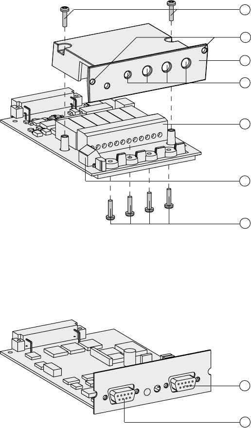
1. Presentation
1.5 Relay communication card
1.6 JBus communication card
Screws to secure the cover
Card fixing holes
Protection cover
Openings for cables
Output terminal block
Input terminal block
Screws to block cables
41
44
43
42
45
47
46
49
48 RS232 connector
RS485 connector
34020113EN/AA - Page 11
>250 mm
>350 mm
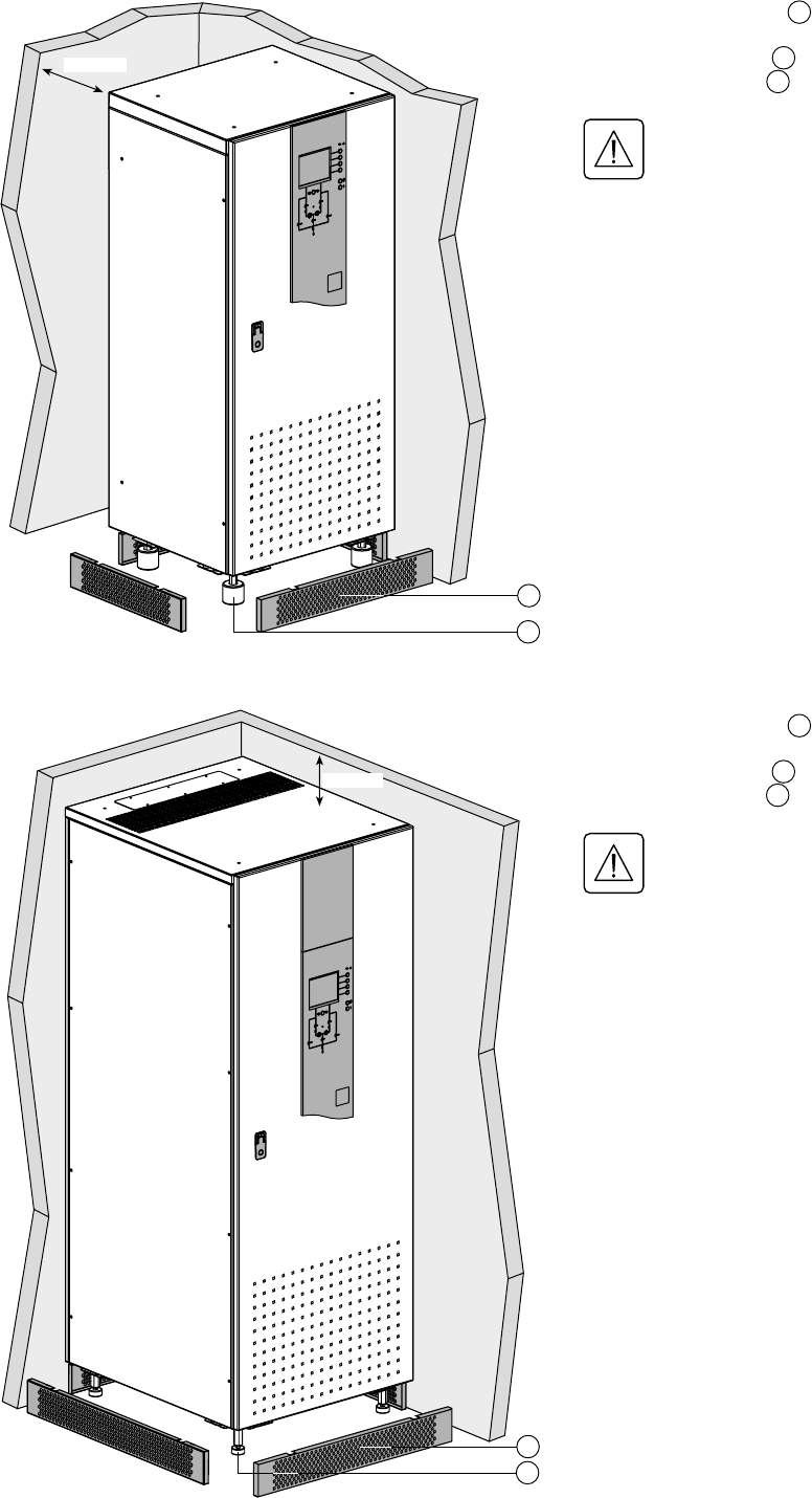
2. Installation
2.1 Positioning
Upsilon STS 30 - 60 - 100 - 160 - 250 A (cabinet 1400 mm high)
Upsilon STS 30 - 60 - 100 - 160 - 250 - 400 - 600 A (cabinet 1900 mm high)
1 - Unclip the base panels 14 .
2 - Set the cabinet to a level position using
the adjustable foot pads 15 .
3 - Put the base panels 14 back in place.
Important: correct ventilation
requires at least 250 mm of free
space behind the cabinet.
14
15
15
1 - Unclip the base panels 14 .
2 - Set the cabinet to a level position using
the adjustable foot pads 15 .
3 - Put the base panels 14 back in place.
Important: correct ventilation
requires at least 350 mm of free
space above the cabinet.
14
Page 12 - 34020113EN/AA
PEN
N
PE PEN
S1 S2
N L1 L2 L3 N L1 L2 L3 N L1 L2 L3
PEN
N
PEN PEN
S1 S2
N L1 L2 L3 N L1 L2 L3 N L1 L2 L3
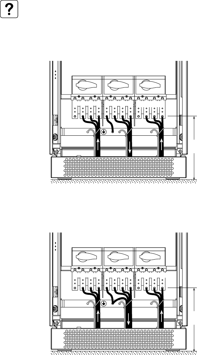
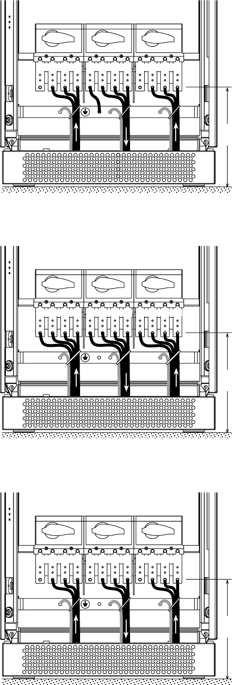
2. Installation
Upsilon STS 30 to 250 A Input: 3 phases + PEN
Output: 3 phases + PEN
Upsilon STS 30 to 250 A Input: 3 phases + PEN
Output: 3 phases + PE + Neutral
See section 1.3 for information on accessing
the connections.
Connections are made using lugs connected
to threaded studs (diameter 8 mm).
The cables are tied to the earth bar.
See section 1.3 for information on accessing
the connections.
Connections are made using lugs connected
to threaded studs (diameter 8 mm).
The cables are tied to the earth bar.
See section 6.1 for information on sizing protection devices and cables (Appendix, Technical data).
Two cables maximum may be used per phase.
2.2 Power connections
275 mm
275 mm
34020113EN/AA - Page 13
PEN
N
PE PEN
S1 S2
N L1 L2 L3 N L1 L2 L3 N L1 L2 L3
PE
N
PE PE
NN
S1 S2
N L1 L2 L3 N L1 L2 L3 N L1 L2 L3
PE PE PE
S1 S2
N L1 L2 L3 N L1 L2 L3 N L1 L2 L3
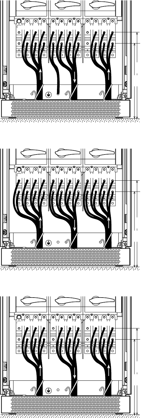
2. Installation
See section 1.3 for information on accessing
the connections.
Connections are made using lugs connected
to threaded studs (diameter 8 mm).
The cables are tied to the earth bar.
See section 1.3 for information on accessing
the connections.
Connections are made using lugs connected
to threaded studs (diameter 8 mm).
The cables are tied to the earth bar.
Upsilon STS 30 to 250 A Input: 3 phases + PE + Neutral
Output: 3 phases + PE + Neutral
275 mm
275 mm
See section 1.3 for information on accessing
the connections.
Connections are made using lugs connected
to threaded studs (diameter 8 mm).
The cables are tied to the earth bar.
275 mm
Upsilon STS 30 to 250 A Input: 3 phases + PEN
Output: 3 phases + PE
Upsilon STS 30 to 250 A Input: 3 phases + PE
Output: 3 phases + PE
Page 14 - 34020113EN/AA
N
PEN
N
PE PEN
S1 S2
N L1 L2 L3 N L1 L2 L3 N L1 L2 L3
N
PEN PEN PEN
S1 S2
N L1 L2 L3 N L1 L2 L3 N L1 L2 L3
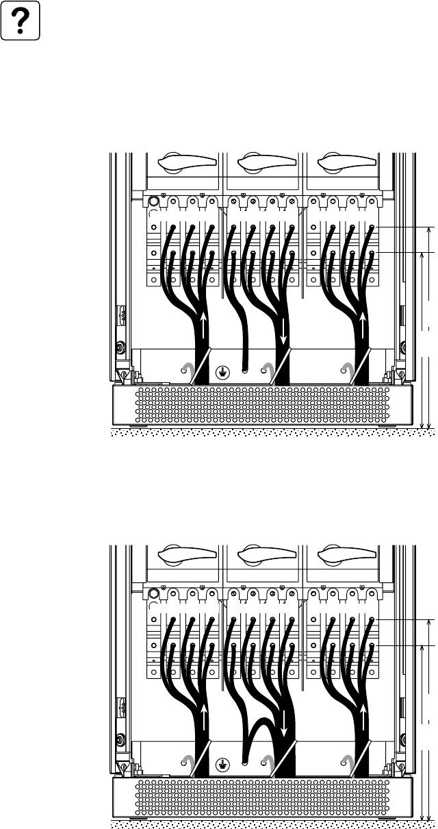
Upsilon STS 400 to 600 A Input: 3 phases + PEN
Output: 3 phases + PEN
See section 1.3 for information on accessing
the connections.
Connections are made using lugs connected
to two threaded studs per phase (diameter
10 mm).
The cables are tied to the earth bar.
2. Installation
463
mm
403
mm
See section 6.1 for information on sizing protection devices and cables (Appendix, Technical data).
A maximum of four cables may be used per phase.
Upsilon STS 400 to 600 A Input: 3 phases + PEN
Output: 3 phases + PE + Neutral
See section 1.3 for information on accessing
the connections.
Connections are made using lugs connected
to two threaded studs per phase (diameter
10 mm).
The cables are tied to the earth bar.
463
mm
403
mm
34020113EN/AA - Page 15
N
PEN PE PEN
S1 S2
N L1 L2 L3 N L1 L2 L3 N L1 L2 L3
PE PE PE
NN N
S1 S2
N L1 L2 L3 N L1 L2 L3 N L1 L2 L3
PE PE PE
S1 S2
N L1 L2 L3 N L1 L2 L3 N L1 L2 L3
2. Installation
Upsilon STS 400 to 600 A Input: 3 phases + PE + Neutral
Output: 3 phases + PE + Neutral
See section 1.3 for information on accessing
the connections.
Connections are made using lugs connected
to two threaded studs per phase (diameter
10 mm).
The cables are tied to the earth bar.
See section 1.3 for information on
accessing the connections.
Connections are made using lugs
connected to two threaded studs per phase
(diameter 10 mm).
The cables are tied to the earth bar.
463
mm
403
mm
463
mm
403
mm
See section 1.3 for information on
accessing the connections.
Connections are made using lugs
connected to two threaded studs per phase
(diameter 10 mm).
The cables are tied to the earth bar.
463
mm
403
mm
Upsilon STS 400 to 600 A Input: 3 phases + PEN
Output: 3 phases + PE
Upsilon STS 400 to 600 A Input: 3 phases + PE
Output: 3 phases + PE
Page 16 - 34020113EN/AA
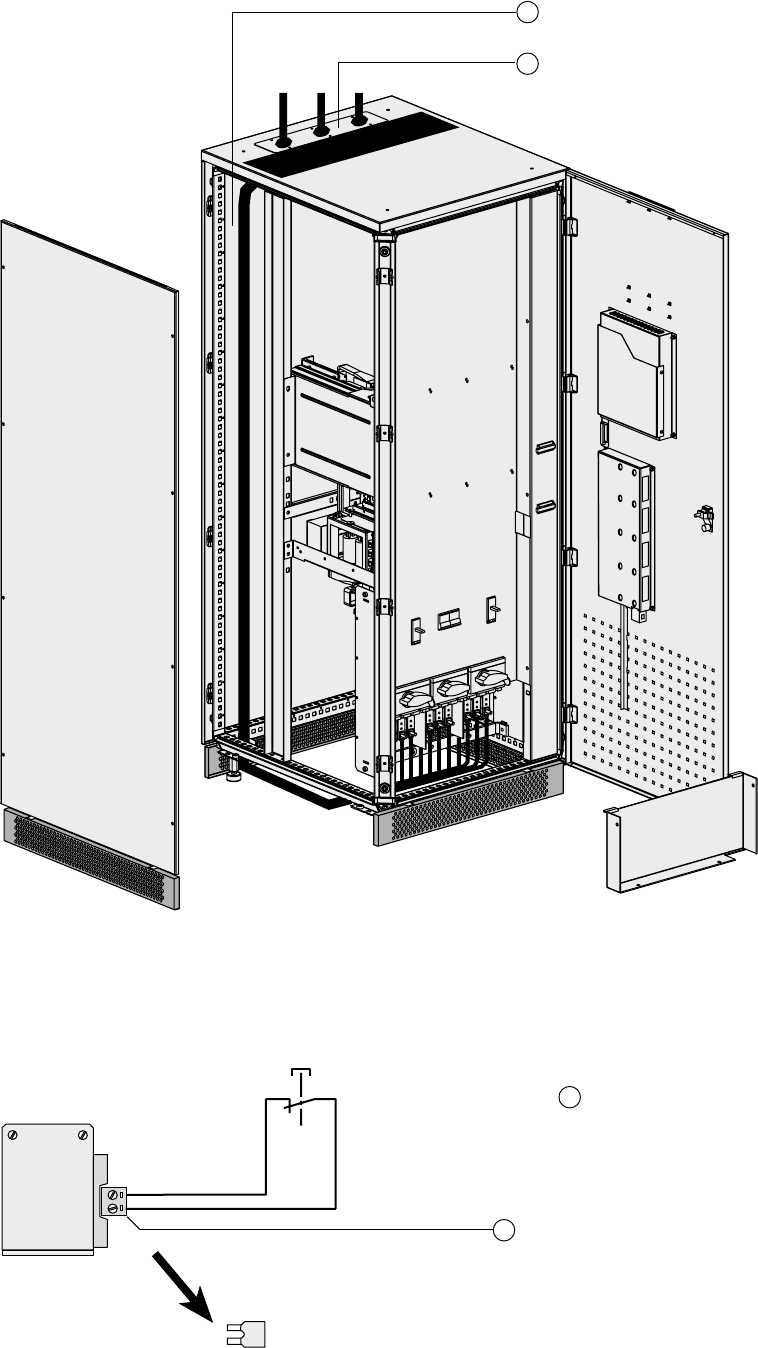
Cable running for cables entering through the top of the Upsilon STS 30 to 250 A
cabinet
16
17
Cable-running zone for cables entering
through the top
Cable gland plate that must be drilled to
cable size
2. Installation
16
1
2
2.3 Connection of the emergency power off terminal block
1 - Remove the jumper from terminal block
16 .
2 - Connect the emergency power off NC
contact to terminals 1 and 2.
3 - Tie the cable down as illustrated in
section 2.4.
34020113EN/AA - Page 17
JBUS/MODBUS
2. Installation
2.4 Connection of the communication cards
Tie the cables to the cable way on the door.
Do not run the control wires with
the power cables.
Two slots are available in the card
cage 5 for additional cards.
2.5 Connection of the JBUS communication card
RS232:
Pin 2: Rxd (or Txd)
Pin 3: Txd (or Rxd)
Pin 5: Earth
RS485:
Pin 4: R-
Pin 5: T-
Pin 8: R+
Pin 9: T+
For information on using the
communication card, see the
JBUS communication card
manual.
Only one communication port
(the RS232 OR the RS485) may
be used at a time.
5
12345
6789
Page 18 - 34020113EN/AA
123456
A
B
2. Installation
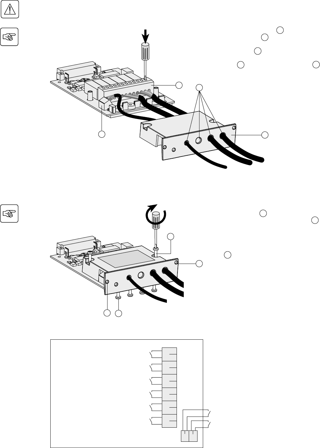
2.6 Connection of the relay communication card
1 - Remove the screws 41 and the
protection cover 43 .
2 - Run the communication cables through
the openings 44 .
3 - Connect the cables to the input terminal
block 46 and the output terminal block 45 .
4 - Put the cover back in place and secure it
with the screws 41 .
5 - Secure the cables using the screws 47 .
6 - Note the position of the power sources
on the labels.
7 - Insert the card in its slot.
8 - Secure the card using the two screws
42 .
46
Characteristics of the output contacts:
Permissible voltage: 250 V AC, 30 V DC
Permissible current: 2 A
Cable: 4 x 0.93 mm2, Ø 6.6 mm ±0.3 mm.
Characteristics of the input contacts:
Switched voltage: 5 V DC
Current drawn: 10 mA
Cable: 4 x 0.34 mm2, Ø 5 mm ±0.5 mm.
41
42
47
42
Before proceeding, disconnect all power sources connected to the card.
Do not mix very low safety voltage (VLSV) and non-VLSV circuits on the card outputs.
43
45 44
6
5
4
3
2
1
BA
Source S2 status condition (active or inactive)
Source S1 status condition (active or inactive)
Overload status condition
STS fault
General alarm
(fault on one of the sources or on the STS)
Load-supplied status condition
(presence or absence of power to the load)
Command to disable transfer (transfer to alternate
source inhibited)
Memorised faults reset command
34020113EN/AA - Page 19
Q1BP
Q1 Q2
Q2BP
Q3
S1 S2
Q1 Q5 Q6 Q2
Q1BP Q2BPQ3
0
1
0
1
000
111
3. Operation
3.1 Start-up
3.2 Shutdown
1 - Check that the two sources are
energised (voltage present).
2 - Set circuit breakers Q5 2 and Q6 3
to the ON position (position 1).
3 - Turn switch Q1BP 6 to the ON position
(position 1). LEDs 37 and 38 go on.
The load is supplied by Source 1 via the
bypass.
4 - Set switches Q1 1 and Q3 7 to the
ON position (position 1). LEDs 29 , 31 ,
and 36 go on.
5 - Turn switch Q1BP 6 back to the OFF
position (position 0). LED 37 goes off.
6 - Set switch Q2 4 to the ON position
(position 1). LEDs 30 and 32 go on.
The load is supplied by Source 1.
If LED 33 is red or off, if LEDs
31 and/or 32 are orange or
red: see section "Maintenance".
1 - Set switches Q1 1 , Q2 4 and Q3 7
to the OFF position (position 0).
2 - Set circuit breakers Q5 2 and Q6 3
to the OFF position (position 0).
All LEDs should go off.
The load is not supplied with power.
Dangerous voltage levels are
still present inside the Upsilon
STS cabinet, in the connection
zone.
1
2
3
4
6
7
1
2
3
4
7
Q1 Q5 Q6 Q2
Q1BP Q2BPQ3
0
1
0
1
000
111
29
30
31
32
33
36
37
38
Make sure that the voltages and frequencies of the two sources S1 and S2 are identical.
Make sure that the voltages of the two sources S1 and S2 are the same as the rated voltage (400 V) of Upsilon STS,
otherwise see section 3.5 (Customization).
Q1BP
Q1 Q2
Q2BPQ3
S1 S2
Page 20 - 34020113EN/AA
Q1BP
Q1 Q2
Q2BP
Q3
S1 S2
Q1BP
Q1 Q2
Q2BP
Q3
S1 S2
Q1BP
Q1 Q2
Q2BP
Q3
S1 S2
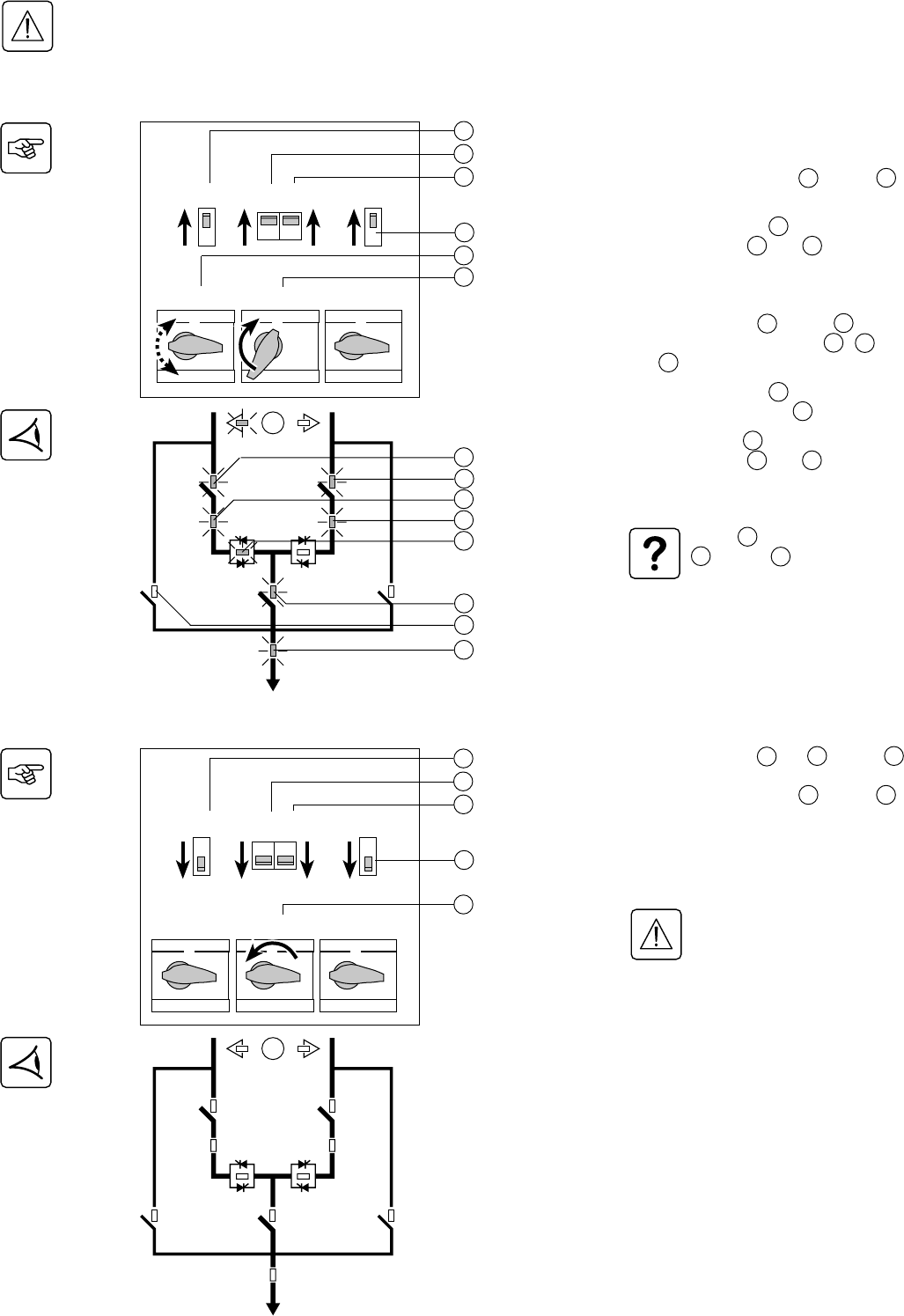
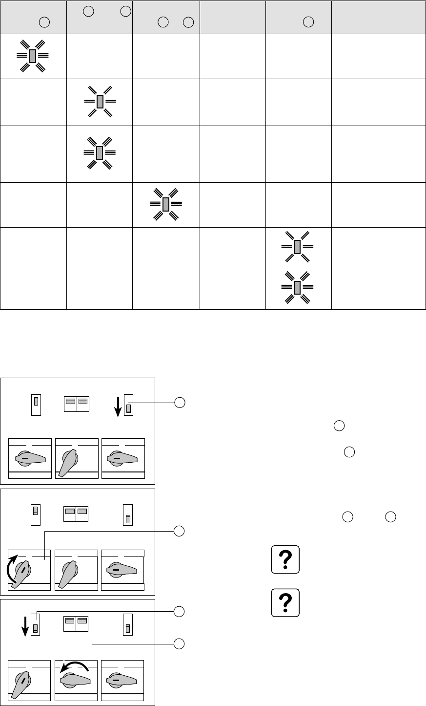
3. Operation
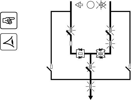
3.3 Normal mode. Operation on preferred source S1
Operation on the preferred source
Automatic transfer to the alternate source
Manual transfer to the alternate source
During normal operation on the preferred
source S1, LEDs 24 , 29 , 30 , 31 , 32 ,
33 , 36 and 38 are on in green.
The load is automatically transferred to the
source offering the highest level of power
quality.
For example, if the preferred source S1
goes outside tolerances, LED 31 goes
orange or red. The buzzer beeps.
Upsilon STS automatically transfers the
load to the alternate source S2. LEDs 24 ,
29 , 30 , 32 , 34 , 36 and 38 are on.
Upsilon STS transfers the load
back to the preferred source S1 as
soon as it returns to within
tolerances.
To stop the buzzer, press the
function button marked .
25
27
1 - Press the manual transfer button 25 :
2 - Confirm the order by pressing the grey
function button 23 marked on the
screen.
LEDs 24 and 27 flash.
After the transfer, the green LED 27 goes
on.
The load is supplied by alternate Source 2.
Transfer is authorised only if the
two sources are within tolerances
(voltage, frequency) and their
phase displacement is within the
set limits. If these two conditions
are not met, the transfer order is
stored in memory and executed
when the voltages cross zero.
If transfer does not take place
within thirty minutes, the order is
cancelled.
29
30
31
32
33
36
38
24
29
30
31
32
36
38
24
34
If LED 38 is orange, there is an
overload.
If LED 38 is red, the load is no
more supplied.
34020113EN/AA - Page 21
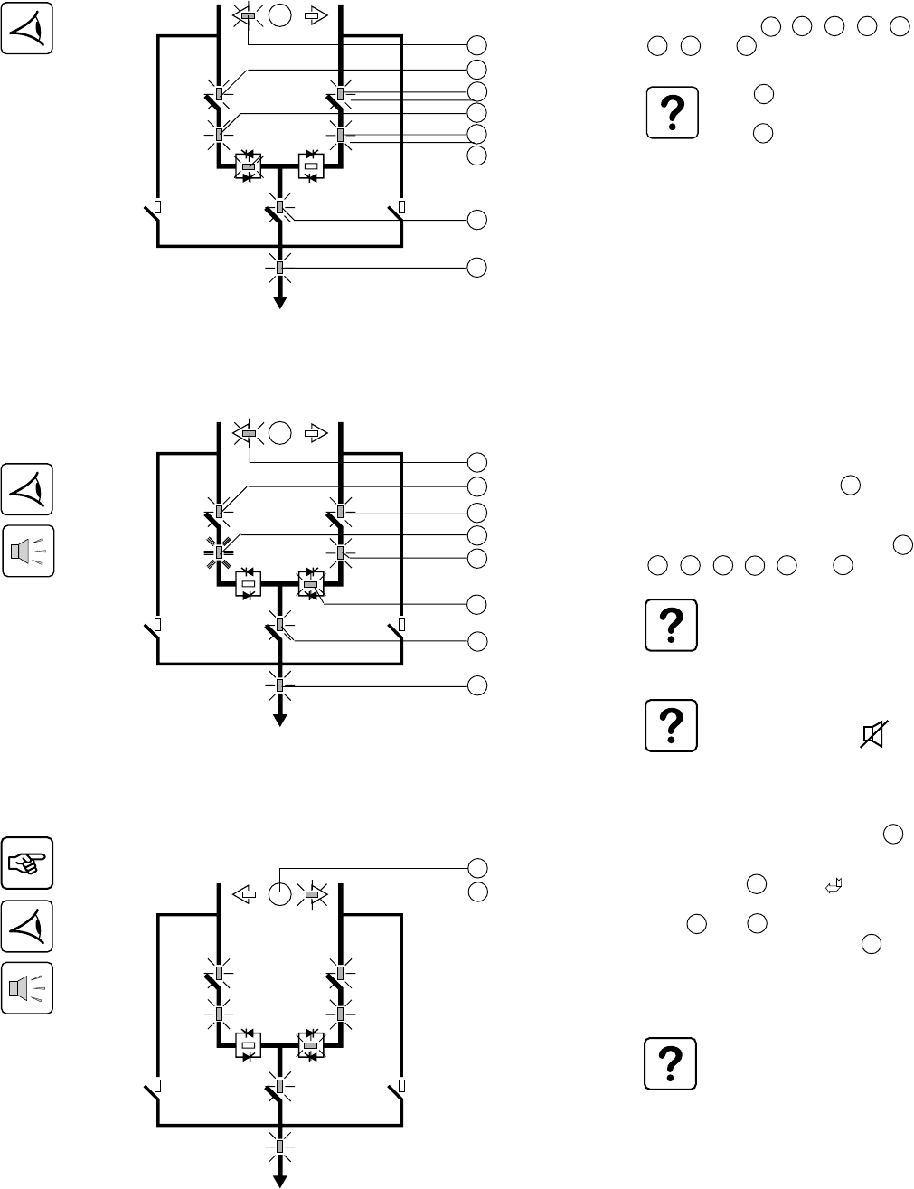
Manual transfer to an out-of-phase alternate source
3. Operation
When the two sources are not in phase, it is
possible to force manual transfer using the
commands on the screen, after entering a
password.
1 - Enter the password (see section 3.5,
Customization).
2 - Follow the instructions provided on the
screen.
Q1BP
Q1 Q2
Q2BP
Q3
S1 S2
Page 22 - 34020113EN/AA
3. Operation
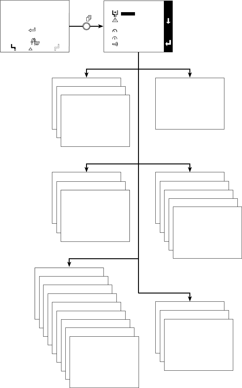
3.4 Display screens
Transfer Alarms
Initial screen
Measurements
Status
Main screen
Transfer
Alarms
Status
Measurements
Setup
Maintenance
MAIN MENU
MANUAL TRANSFERT
Transfer without break
Transfer with break
ALARMS
STATUS
EVENT LOG
STATISTICS
CURRENT MEASUREMENTS
VOLTAGE MEASUREMENTS
FREQUENCY MEASUREMENTS
POWER MEASUREMENTS
LOAD MEASUREMENTS
Maintenance
Setup
SETUP
LANGUAGE
ADJUST DATE AND TIME
CONTRAST
BUZZER VOLUME
SOURCE NAMES
NEW PASSWORD
PERSONALIZATION
DRY CONTACT SETTINGS
E
S
C
VOLT
0101
1010
0101
DOWNGRADED MODE
I1 17 A I2 9 A I3 2 A
1 KW 6 KVA
PF 0.3
preferred
synchro
UPS 1
= 64°
V1 244 V
V2 230 V
V3 232 V
50.0 Hz
UPS 2
V1 232 V
V2 229 V
V3 230 V
50.0 Hz
MAINTENANCE
DISPLAY TEST
UNIT ON BYPASS
34020113EN/AA - Page 23
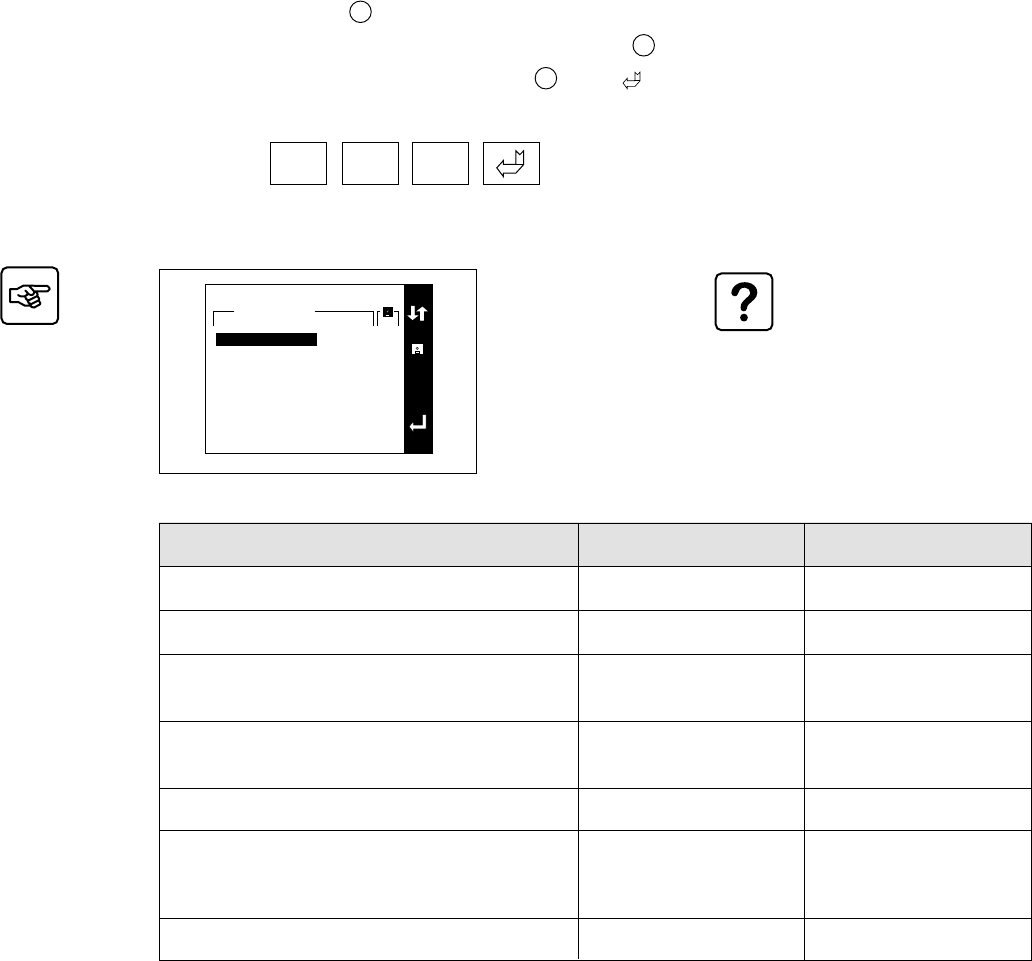
3. Operation
3.5 Upsilon STS customization
The monitoring parameters must
be identical for the two sources.
These parameters depend on the
tolerances of the connected loads.
Return to preferred source after transfer
Nominal source voltage
Overvoltage threshold
Undervoltage threshold
Nominal source frequency
Frequency tolerances
Phase error tolerance between the two sources
Factory setting
Automatic
400 V
Un +10%
Un -10%
50 Hz
±5%
±15°
Customization
Manual / Automatic
380 / 400 / 415 V
Un +5% to Un +20%
in 1% steps
Un -5% to Un -20%
in 1% steps
50 / 60 Hz
+1% to +10%
-1% to -10%
in 0.5% steps
±1° to ±45° in 1° steps
1 - Press the menu button 26 .
2 - Select "Setup", then "Customization" using the function buttons 23 marked or .
3 - Confirm the order by pressing the function button 23 marked .
4 - Enter the password.
The password
ØØØ
is set in the factory.
Select "Setup", then "Password" to personalise the password.
PERSONALIZATION
E
S
C
Current settings
400 V
10%
10%
50 Hz
5%
5%
15°
YES
Nominal voltage
Overvoltage threshold
Undervoltage threshold
Nominal frequency
Overfrequency threshold
Underfrequency threshold
Phase sync tolerance
Retransfer
Page 24 - 34020113EN/AA
Outputs Signals available on each contact
- Load-supplied status condition (presence or
absence of power to the load).
- General alarm (fault on one of the sources or
on the Upsilon STS).
- Upsilon STS fault.
- Source S1 status condition (within or outside
tolerances).
- Source S2 status condition (within or outside
tolerances).
- Phase-error condition between the two
sources (within or outside tolerances).
- Source S1 status condition (active or inactive).
- Source S2 status condition (active or inactive).
- Preferred-source status condition (S1 inactive
and S2 active).
- Automatic-transfer status condition
(authorised or not).
- Overload status condition.
Factory setting
1.1 - Load-supplied status condition (presence or
absence of power to the load).
- General alarm (fault on one of the sources or
on the Upsilon STS).
- Upsilon STS fault.
- Overload status condition.
- Source S1 status condition (active or inactive).
- Source S2 status condition (active or inactive).
1.2
1.3
1.4
1.5
1.6
Inputs Signals available on each contact
- Memorised faults reset command.
- Selection command for source S1.
- Selection command for source S2.
- Selection command for the authorised
automatic retransfer mode.
- Selection command for the inhibited automatic
retransfer mode.
- Command to authorise transfer.
- Command to disable transfer.
- EPO command (enables the opening
command for switches Q1 and Q2).
Factory setting
1.A - Memorised faults reset command.
- Command to disable transfer.
1.B
3.6 Customization of the relay communication card
3. Operation
34020113EN/AA - Page 25
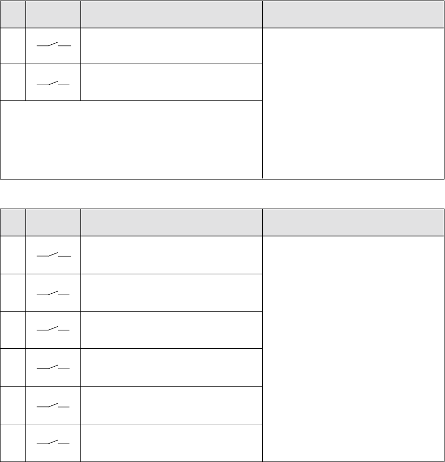
4. Maintenance
4.1 Identification of anomalies
4.2 Transfer to the manual bypass
Transfer to the manual bypass for source
S1:
1 - Manually transfer the load to source S1.
2 - Set switch Q2 4 to the OFF position
(position 0).
3 - Set switch Q1BP 6 to the ON position
(position 1).
The load is supplied by source S1 via the
bypass.
4 - Set switches Q1 1 and Q3 7 to the
OFF position (position 0).
The operation for source S2 is
identical, using switches Q2 and
Q2BP.
Interlocking of the bypass lines is
ensured by use of a single key that
must be inserted on the bypass
switch to be operated.
General-alarm
LED 21
-
-
-
-
-
S1 31 or S2 32
LED
-
-
-
-
Static-switch
LED 33 or 34
-
-
-
-
-
The meaning of all these anomalies are detailed on the display:
Select the alarm: the corresponding informations are displayed.
Buzzer
Beeps
Beeps
Beeps
Beeps
-
-
Meaning
Internal STS fault.
Source outside
tolerances, load still
supplied.
Source outside
tolerances, no voltage.
The load cannot be
supplied by this source.
Static-switch fault.
Overload.
Load not supplied.
System output
LED 38
-
-
-
-
Q1 Q5 Q6 Q2
Q1BP Q2BPQ3
0
1
0
1
000
111
Q1 Q5 Q6 Q2
Q1BP Q2BPQ3
0
1
0
1
000
111
Q1 Q5 Q6 Q2
Q1BP Q2BPQ3
0
1
0
1
000
111
1
4
6
7
Page 26 - 34020113EN/AA
5. Environment
This product has been designed to respect the environment
It does not contain CFCs or HCFCs.
It is manufactured on a production site certified ISO 14001.
UPS recycling at the end of service life
MGE UPS SYSTEMS undertakes to recycle, by certified companies and in compliance with all applicable regulations, all
products recovered at the end of their service life (contact your MGE UPS SYSTEMS branch office).
Packing
Packing materials must be recycled in compliance with all applicable regulations.
Web site: www.mgeups.com
34020113EN/AA - Page 27
6. Appendix
6.1 Technical data
Output currents and voltage
Rated output current:
Input and output voltage:
◗ Rated operating voltage:
◗ Maximum voltage:
◗ Minimum voltage:
◗ Rated frequency:
30 A
380 V / 400 V / 415 V
498 V (415 V +20%)
247 V (380 V -35%)
50 or 60 Hz (45 Hz minimum, 66 Hz maximum)
60 A 100 A 160 A 250 A 400 A 600 A
Permissible-overload curve
◗ During an overload, transfer between sources is disabled.
◗ Overloads higher than 1.5 In are stored in memory. The alarm must be reset to return to normal operation.
Thermal characteristics
(1) These characteristics are calculated for a voltage of 400 V and a power factor of 0.8.
Heat losses (1):
◗ at rated power:
◗ at 50% rated power:
Required ventilation:
195 W
150 W
350 m3/h
295 W
195 W
350 m3/h
430 W
260 W
350 m3/h
615 W
350 W
1600 m3/h
920 W
495 W
1600 m3/h
1420 W
735 W
2300 m3/h
2150 W
1070 W
2300 m3/h
Noise level
Recommended protection devices upstream of Upsilon STS
Cable sizes
Noise in dB (ISO 3746):
Cross-sectional area in mm2 : 50 50 50 120 120 240 240
Type of circuit breaker:
◗ TNS system:
◗ TNC system:
Trip unit:
Thermal setting:
Magnetic setting:
C60L 32A
curve C
1.05 In
10xIn
NS100H 4P 4D
NS100H 3P
STR22SE
≤1.05 In
≤10xIn
NS160H
4P 4D
NS160H
3P
STR22SE
≤1.05 In
≤10xIn
NS400H
4P 4D
NS400H
3P
STR23SE
≤1,05 In
≤10xIn
NS250H
4P 4D
NS250H
3P
STR22SE
≤1.05 In
≤10xIn
NS630H
4P 4D
NS630H
3P
STR23SE
≤1.05 In
≤10xIn
55 55 55 59 59 59 59
In
2 In
4 In
8 In
32 In
16 In
t(s)
0.01 s 0.1 s 1 s 10 s 100 s 1000 s
Page 28 - 34020113EN/AA
Upsilon STSUpsilon STS Upsilon STS
Q1
Upsilon STS
Q2
Q3 Q2BPQ1BP
S1 S2
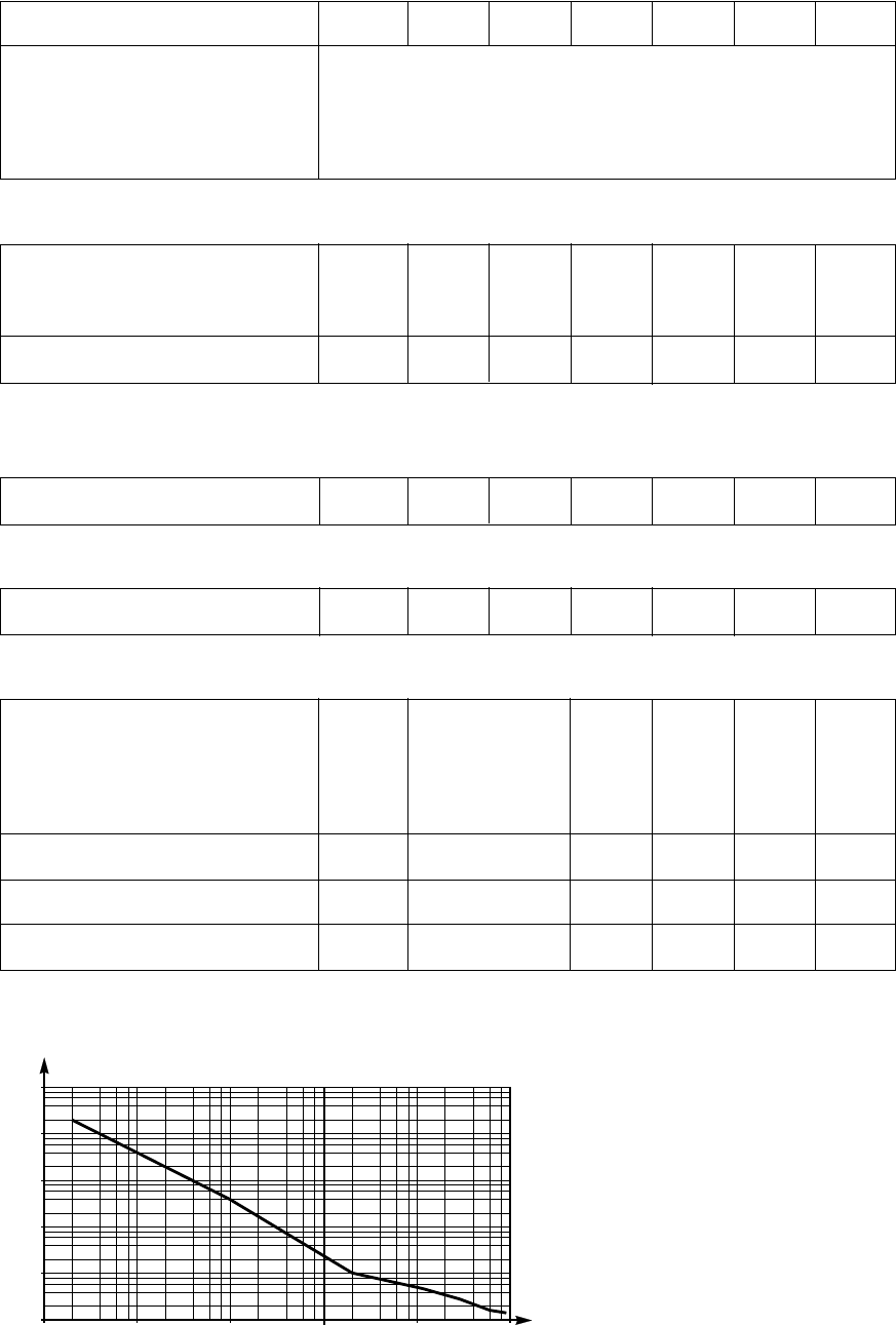
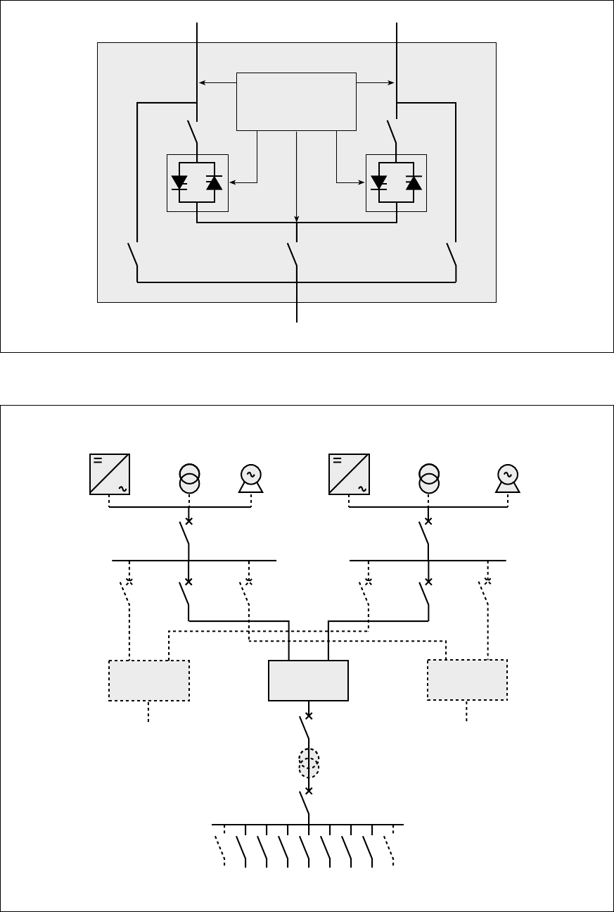
6. Appendix
6.2 Simplified diagrams
Upsilon STS simplified diagram
Simplified diagram of an installation
Static-switch
control/monitoring
Source 2
Source 1
To the load
Alternate sources
Preferred sources
To the load
34020113EN/AA - Page 29
6. Appendix
6.3 Glossary
Alternate source Backup source that steps in if the preferred source fails.
JBUS communication card Internal card implementing the JBus protocol on a serial link to supply the user with
system information.
Load Device(s) or system(s) connected the Upsilon STS output.
Manual bypass Q1BP, Q3 and Q2BP switches, accessible to the user, that may be used to directly
supply the load from Source S1 or S2. The bypass enables servicing on the equipment
without interrupting the supply of power to the load.
Normal mode Operating mode during which the load is supplied by the preferred source.
Preferred source Source selected as the normal source of power.
Relay communication card Internal card implementing contacts to supply the user with system information.
Static switch Electronic switch ensuring instantaneous switching.
Page 30 - 34020113EN/AA
6. Appendix
6.4 Index
A
Alarms ............................................................................ 25
Anomalies ...................................................................... 25
B
Buzzer ............................................................................ 25
C
Cable sizes .................................................................... 27
Communication cards
JBUS ...................................................................... 10
Relay ...................................................................... 10
Connections
Access ...................................................................... 8
JBUS communication card ..................................... 17
Power cables .................................. 12, 13, 14, 15, 16
Relay communication card ..................................... 18
Through the top ...................................................... 16
Customization .......................................................... 23, 24
D
Dimensions ...................................................................... 7
Display ........................................................................... 22
F
Faults ............................................................................. 25
Frequency ...................................................................... 27
L
Layout of components ...................................................... 8
LEDs .......................................................................... 9, 25
Links
RS232 .................................................................... 10
RS485 .................................................................... 10
Losses ............................................................................ 27
M
Man / machine interface ................................................... 9
Manual bypass ............................................................... 25
O
Operating modes ..................................................... 20, 21
Overloads ....................................................................... 27
R
Recommended protection .............................................. 27
Recycling ....................................................................... 26
S
Safety rules ...................................................................... 3
Shutdown ....................................................................... 19
Start-up .......................................................................... 19
V
Ventilation ...................................................................... 27
Voltages ......................................................................... 27
W
Weight .............................................................................. 7
