Mge Ups Systems Ex 5Rt Users Manual 86 86000 00 A01 UM
EX 11RT 742fa8aa-19e7-4c4d-bccf-aefafc33a882
EX 5RT to the manual 742fa8aa-19e7-4c4d-bccf-aefafc33a882
2015-02-09
: Mge-Ups-Systems Mge-Ups-Systems-Ex-5Rt-Users-Manual-555672 mge-ups-systems-ex-5rt-users-manual-555672 mge-ups-systems pdf
Open the PDF directly: View PDF ![]() .
.
Page Count: 72
EX 5RT / EX 7RT/ EX 11RT System
Installation and User Manual
86-86000-00 A01
www.mgeups.com

IMPORTANT SAFETY INSTRUCTIONS
SAVE THESE INSTRUCTIONS – This manual contains important instructions for MGE UPS SYSTEMS, INC. products that must
be followed during operation and maintenance of the equipment.
WARNING Opening enclosures expose hazardous voltages. Always refer service to
qualified personnel only.
ATTENTION L'ouverture des cabinets expose des tensions dangereuses. Assurez-vous toujours
que le service ne soit fait que par des personnes qualifiees.
WARNUNG! Das öffnen der Gehäuse legen gefährliche Spannungen bloss. Service sollte immer
nur von qualifizierten Personal durchgeführt werden.
WARNING As standards, specifications, and designs are subject to change, please ask for con-
firmation of the information given in this publication.
ATTENTION Comme les normes, spécifications et produits peuvent changer, veuillez demander
confirmation des informations contenues dans cette publication.
WARNUNG! Normen, Spezifizierungen und Pläne unterliegen Anderungen. Bitte verlangen Sie
eine Bestätigung über alle Informationen, die in dieser Ausgabe gemacht wurden.
NOTE This equipment has been tested and found to comply with the limits for a Class A
digital device, pursuant to part 15 of the FCC rules. These limits are designed to pro-
vide reasonable protection against harmful interference when the equipment is
operated in a commercial environment.
This equipment generates, uses, and can radiate radio frequency energy and, if not
installed and used in accordance with the instruction manual, may cause harmful
interference to radio communications. Operation of this equipment in a residential
area is likely to cause harmful interference in which case the user will be required to
correct the interference at user's own expense.
Certification Standards
◗IEEE 587-1980/ANSI C62.41 1980 Standards for Surge Withstand Ability
◗FCC rules and regulations of Part 15, Subpart J, Class A
◗UL listed under 1778, Standards for Uninterruptible Power Supply Equipment
◗IEC 61000-4-2 (ESD) : level4.
◗IEC 61000-4-3 (Radiated field) : level 3.
IEC 61000-4-4 (EFT) : level4.
◗IEC 61000-4-5 (Fast transients) : level4.
◗IEEE-C6241 Category B (ring wave).
◗IEC 61000-4-6 (electromagnetic field).
◗IEC 61000-4-8 (conducted magnetic field).
EX 5/7/11 RT System
Important Safety Information and Standardsii 86-86000-00 A01

Installation and User Manual
Safety of Persons
◗
The UPS has its own internal power source (the battery). Consequently, the power outlets may be energized even if the UPS is disconnected from
the AC power source.
◗
The UPS must be properly grounded.
◗
The battery supplied with the UPS contains small amounts of toxic materials. To avoid accidents, the directives listed below must be observed:
- Never burn the battery (risk of explosion).
- Do not attempt to open the battery (the electrolyte is dangerous for the eyes and skin).
- Comply with all applicable regulations for the disposal of the battery.
- Batteries constitute a danger (electrical shock, burns). The short-circuit current may be very high. Precautions must be taken for all handling:
remove watches, rings, bracelets and any other metal objects, use tools with insulated handles.
- Do not lay tools or metal parts on top of batteries.
Product Safety
◗
A protection circuit breaker must be installed upstream and be easily accessible..
◗
The UPS can be disconnected from the AC power source by opening the input circuit breaker.
◗
UPS must be connected to a nearby power source that is easily accessible.
◗
Never block the ventilation grates of the UPS.
◗
The UPS must be installed in a controlled environment.
Special Precautions
◗
The UPS connection instructions and operation described in the manual must be followed in the indicated order.
◗
Check that the indications on the rating plate correspond to your AC powered system and to the actual electrical consumption of all the equipment
to be connected to the UPS.
◗
Before and after the installation, if the UPS remains de-energized for a long period, the UPS must be energized for a period of 24 hours, at least
once every 6 months (for a normal storage temperature less than 25°C). This charges the battery, thus avoiding possible irreversible damage.
How to use this manual and Symbol Usage
This manual is designed for ease of use and easy location of information.
Typographical conventions use “< >” angle brackets in procedures to denote a prompt for User action:
For example:
1. After the selections are complete, click on the <Save> button.
This manual uses four icon symbols with text to convey important information and tips.
WARNING Indicates information provided to protect the user and service personnel against safety
hazards and/or possible equipment damage.
CAUTION Indicates information provided to protect the user and service personnel against possible
equipment damage.
IMPORTANT Indicates information provided as an operating instruction, or as an operating tip.
NOTE Indicates information provided as an operating tip or an equipment feature.
Safety of Persons iii86-86000-00 A01

EX 5/7/11 RT System
CAUTION: Record all serial numbers!
CAUTION: Record All Serial Numbers!
RECORD ALL SERIAL NUMBERS FOR EX 5/7/11 RT AND ACCESSORIES.
THESE SERIAL NUMBERS WILL BE REQUIRED IF YOUR SYSTEM NEEDS SERVICE.
KEEP THIS MANUAL IN A PLACE WHERE YOU CAN REFERENCE THE SERIAL
NUMBERS IF SERVICE IS REQUIRED!
EX 5RT System EX 7RT System EX 11RT System
Power Module SERIAL NUMBER: ___________________________________________________
Battery Module SERIAL NUMBER: ____________________________________________________
Transformer SERIAL NUMBER: ______________________________________________________
ADDITIONAL MODULES SERIAL NUMBERS:
____________________________ ______________________________
____________________________ ______________________________
____________________________ ______________________________
____________________________ ______________________________
____________________________ ______________________________
____________________________ ______________________________
____________________________ ______________________________
____________________________ ______________________________
____________________________ ______________________________
____________________________ ______________________________
iv 86-86000-00 A01

Installation and User Manual
v86-86000-00 A01
EX 5/7/11 RT System
Installation and User Manual
Revision History
EX 5RT / EX 7RT / EX 11RT System
Installation and User Manual
86-86000-00
Revision: A00 Initial Release 07/2004
Copyright © 2004 MGE UPS SYSTEMS, INC.
All rights reserved. Printed in U.S.A.
MGE UPS SYSTEMS, INC.
1660 Scenic Avenue
Costa Mesa, CA 92626
(714) 557-1636
For Service Call:
1 (800) 438-7373

(This page left blank intentionally)
EX 5/7/11 RT System
vi 86-86000-00 A01

Contents
Contents
c i86-86000-00 A01
section description . . . . . . . . . . . . . . . . . . . . . . . . . . . . . . . . . . . . . . . . . . .page
IMPORTANT SAFETY INSTRUCTIONS . . . . . . . . . . . . . . . . . . . . . . .ii
Certification Standards . . . . . . . . . . . . . . . . . . . . . . . . . . . . . . . . . . . .ii
Safety of Persons . . . . . . . . . . . . . . . . . . . . . . . . . . . . . . . . . . . . . . . .iii
How to use this manual and Symbol Usage . . . . . . . . . . . . . . . . . . . .iii
CAUTION: Record All Serial Numbers! . . . . . . . . . . . . . . . . . . . . . . .iv
Revision History . . . . . . . . . . . . . . . . . . . . . . . . . . . . . . . . . . . . . . . . . .v
Section 1 Introduction
section description . . . . . . . . . . . . . . . . . . . . . . . . . . . . . . . . . . . . . . . . . . .page
1.0 Scope . . . . . . . . . . . . . . . . . . . . . . . . . . . . . . . . . . . . . . . . . . . . .1 — 1
1.1 System Electrical Characteristics . . . . . . . . . . . . . . . . . . . . . . . .1 — 4
1.2 Standard Configurations . . . . . . . . . . . . . . . . . . . . . . . . . . . . . . .1 — 4
1.2.1 Tower Configuration . . . . . . . . . . . . . . . . . . . . . . . . . . . . . . . . . . .1 — 4
1.2.2 Rack Configuration . . . . . . . . . . . . . . . . . . . . . . . . . . . . . . . . . . .1 — 5
1.3 Rear Panels . . . . . . . . . . . . . . . . . . . . . . . . . . . . . . . . . . . . . . . . .1 — 6
1.3.1 Power Module EX 5/7/11 RT . . . . . . . . . . . . . . . . . . . . . . . . . . . .1 — 6
1.3.2 Battery Module EXB 5/7/11 RT With Emergency
Power Off (EPO) Function . . . . . . . . . . . . . . . . . . . . . . . . . . . . . .1 — 6
1.3.3 EX RT Transformer Module . . . . . . . . . . . . . . . . . . . . . . . . . . . .1 — 7
1.4 Display and Control Panel . . . . . . . . . . . . . . . . . . . . . . . . . . . . . .1 — 7
1.5 Optional Accessories . . . . . . . . . . . . . . . . . . . . . . . . . . . . . . . . . .1 — 8
1.5.1 Power Module Rail Kit . . . . . . . . . . . . . . . . . . . . . . . . . . . . . . . . .1 — 8
1.5.2 Battery/ Transformer/CLA Module Rail Kit . . . . . . . . . . . . . . . . . .1 — 8
1.5.3 Battery Module with Remote Emergency
Power Off (REPO) Function . . . . . . . . . . . . . . . . . . . . . . . . . . . .1 — 9
1.5.4 Battery Extension Cable Kit . . . . . . . . . . . . . . . . . . . . . . . . . . . .1 — 9
1.5.5 Battery Integration Kit with Casters . . . . . . . . . . . . . . . . . . . . . .1 — 10
1.5.6 Input/Output Box . . . . . . . . . . . . . . . . . . . . . . . . . . . . . . . . . . . .1 — 10
1.5.7 Transformer Module . . . . . . . . . . . . . . . . . . . . . . . . . . . . . . . . . .1 — 11
1.5.8 CLA Module (Long backup time charger) . . . . . . . . . . . . . . . .1 — 12

EX 5/7/11 RT System
Contentsc ii 86-86000-00 A01
Section 2 Setup and Installation
section description . . . . . . . . . . . . . . . . . . . . . . . . . . . . . . . . . . . . . . . . . . .page
2.0 Scope . . . . . . . . . . . . . . . . . . . . . . . . . . . . . . . . . . . . . . . . . . . . .2 — 1
2.1 Unpacking and Parts Check . . . . . . . . . . . . . . . . . . . . . . . . . . . .2 — 1
2.2 Contents of EX 5/7/11 RT System . . . . . . . . . . . . . . . . . . . . . . .2 — 2
2.3 Installation in Tower Configuration . . . . . . . . . . . . . . . . . . . . . . . .2 — 4
2.4 Installation in Rack Mounting Configuration . . . . . . . . . . . . . . . .2 — 5
2.4.1 Adjustment of Front Panel Logo and control panel for
Rack Orientation. . . . . . . . . . . . . . . . . . . . . . . . . . . . . . . . . . . . . .2 — 5
2.5 Prepare Battery Module for Rack Mounting . . . . . . . . . . . . . . . .2 — 6
2.6 Power or Battery Module Rack Mounting . . . . . . . . . . . . . . . . . .2 — 7
2.6.1 Rear Support Brackets Installation . . . . . . . . . . . . . . . . . . . . . . .2 — 8
2.6.2 Input/Output Box Bracket System Installation . . . . . . . . . . . . . . .2 — 8
2.7 Communication Ports . . . . . . . . . . . . . . . . . . . . . . . . . . . . . . . . .2 — 9
2.7.1 Connecting the RS232 Communication Port . . . . . . . . . . . . . . .2 — 9
2.7.2 Connecting the Dry (Relay) Contact Communication Port . . . .2 — 10
2.7.3 Installation of Optional Network Management Card . . . . . . . .2 — 10
2.7.4 Remote Emergency Power Off (REPO) Communication Port .2 — 12
2.8 Connecting the Input and Output Power Cables to the
Input/Output Box . . . . . . . . . . . . . . . . . . . . . . . . . . . . . . . . . . . .2 — 13
2.8.1 Flexible Cordage and Conduit Installations . . . . . . . . . . . . . . .2 — 13
2.8.2 System Connections with Common Normal and
Bypass AC Sources . . . . . . . . . . . . . . . . . . . . . . . . . . . . . . . . . .2 — 15
2.8.3 Connecting EX RT Transformer . . . . . . . . . . . . . . . . . . . . . . . .2 — 16
2.8.4 System Connections with Separate Normal and
Bypass AC Sources . . . . . . . . . . . . . . . . . . . . . . . . . . . . . . . . . .2 — 17
2.8.5 System Connections as Frequency Converter
(without Bypass AC Source) . . . . . . . . . . . . . . . . . . . . . . . . . . .2 — 18
2.9 Connection of Battery Module, EXB . . . . . . . . . . . . . . . . . . . . .2 — 19
2.10 Connection of CLA Module . . . . . . . . . . . . . . . . . . . . . . . . . . . .2 — 20
Section 3 Operation
section description . . . . . . . . . . . . . . . . . . . . . . . . . . . . . . . . . . . . . . . . . . .page
3.0 Scope . . . . . . . . . . . . . . . . . . . . . . . . . . . . . . . . . . . . . . . . . . . . .3 — 1
3.1 Initial Startup . . . . . . . . . . . . . . . . . . . . . . . . . . . . . . . . . . . . . . . .3 — 1
3.2 UPS Personalization . . . . . . . . . . . . . . . . . . . . . . . . . . . . . . . . . .3 — 2
3.2.1 Accessing personalization with front panel buttons . . . . . . . . . .3 — 2
3.2.2 Accessing personalization through external software . . . . . . . . .3 — 4
3.2.3 Final startup sequence . . . . . . . . . . . . . . . . . . . . . . . . . . . . . . . .3 — 4
3.3 Operating Modes . . . . . . . . . . . . . . . . . . . . . . . . . . . . . . . . . . . . .3 — 5
3.3.1 Normal (double conversion) Mode . . . . . . . . . . . . . . . . . . . . . . .3 — 5
3.3.2 ECO Modes . . . . . . . . . . . . . . . . . . . . . . . . . . . . . . . . . . . . . . . . .3 — 6
3.4 Operation on battery power . . . . . . . . . . . . . . . . . . . . . . . . . . . . .3 — 7
3.4.1 Transfer to Battery Power . . . . . . . . . . . . . . . . . . . . . . . . . . . . . .3 — 7
3.5 Return of Normal AC source . . . . . . . . . . . . . . . . . . . . . . . . . . . .3 — 8
3.6 Shutdown . . . . . . . . . . . . . . . . . . . . . . . . . . . . . . . . . . . . . . . . . . .3 — 8

Installation and User Manual
Section 4 Maintenance
section description . . . . . . . . . . . . . . . . . . . . . . . . . . . . . . . . . . . . . . . . . . .page
4.0 Scope . . . . . . . . . . . . . . . . . . . . . . . . . . . . . . . . . . . . . . . . . . . . .4 — 1
4.1 Information Technology (IT) Network and Industrial
Operating Modes . . . . . . . . . . . . . . . . . . . . . . . . . . . . . . . . . . . . .4 — 1
4.2 Troubleshooting . . . . . . . . . . . . . . . . . . . . . . . . . . . . . . . . . . . . . .4 — 2
4.3 Hot Swapping the Power Module . . . . . . . . . . . . . . . . . . . . . . . .4 — 4
4.4 Re-connecting the power module . . . . . . . . . . . . . . . . . . . . . . . .4 — 5
4.5 Hot Swapping the Battery Module . . . . . . . . . . . . . . . . . . . . . . . .4 — 6
4.5.1 Disconnecting the Battery Module . . . . . . . . . . . . . . . . . . . . . . .4 — 6
4.5.2 Re-connecting the Battery Module . . . . . . . . . . . . . . . . . . . . . . .4 — 6
Section 5 Appendix
section description . . . . . . . . . . . . . . . . . . . . . . . . . . . . . . . . . . . . . . . . . . .page
5.0 Electrical Specifications . . . . . . . . . . . . . . . . . . . . . . . . . . . . . . . .5 — 1
5.1 System Input/Output Power Ratings . . . . . . . . . . . . . . . . . . . . . .5 — 1
5.2 System Overload Characteristics . . . . . . . . . . . . . . . . . . . . . . . .5 — 1
5.3 System Backup Characteristics . . . . . . . . . . . . . . . . . . . . . . . . . .5 — 1
5.4 System Short Circuit Protection . . . . . . . . . . . . . . . . . . . . . . . . .5 — 2
5.5 Accessories Electrical Characteristics . . . . . . . . . . . . . . . . . . . . .5 — 2
5.6 Heat Rejection . . . . . . . . . . . . . . . . . . . . . . . . . . . . . . . . . . . . . . .5 — 2
5.7 Environmental Characteristics . . . . . . . . . . . . . . . . . . . . . . . . . . .5 — 2
MGE Warranty & Propriety Rights
MGE Warranty
Proprietary Rights Statement
Warranty and Product Registration
User Information
Product information
Warranty Extension (Warranty+) not available on products
Technical Support and Field Service
MGE Service and Repair
Who to Contact
Scheduling Field Service Engineer Support
Return for Repair (RMA)
Glossary G — 1
Reorder Form RO — 1
Contents c iii86-86000-00 A01

Figures
figure description . . . . . . . . . . . . . . . . . . . . . . . . . . . . . . . . . . . . . . . . . . . . . . . . .page
1-1: Tower Configurations with Power Module, Battery Module,
and optional Transformer Module. . . . . . . . . . . . . . . . . . . . . . . . . . . . . . .1 — 4
1-2: Rack Configurations with Power Module, Battery Module, and
Transformer Module . . . . . . . . . . . . . . . . . . . . . . . . . . . . . . . . . . . . . . . . .1 — 5
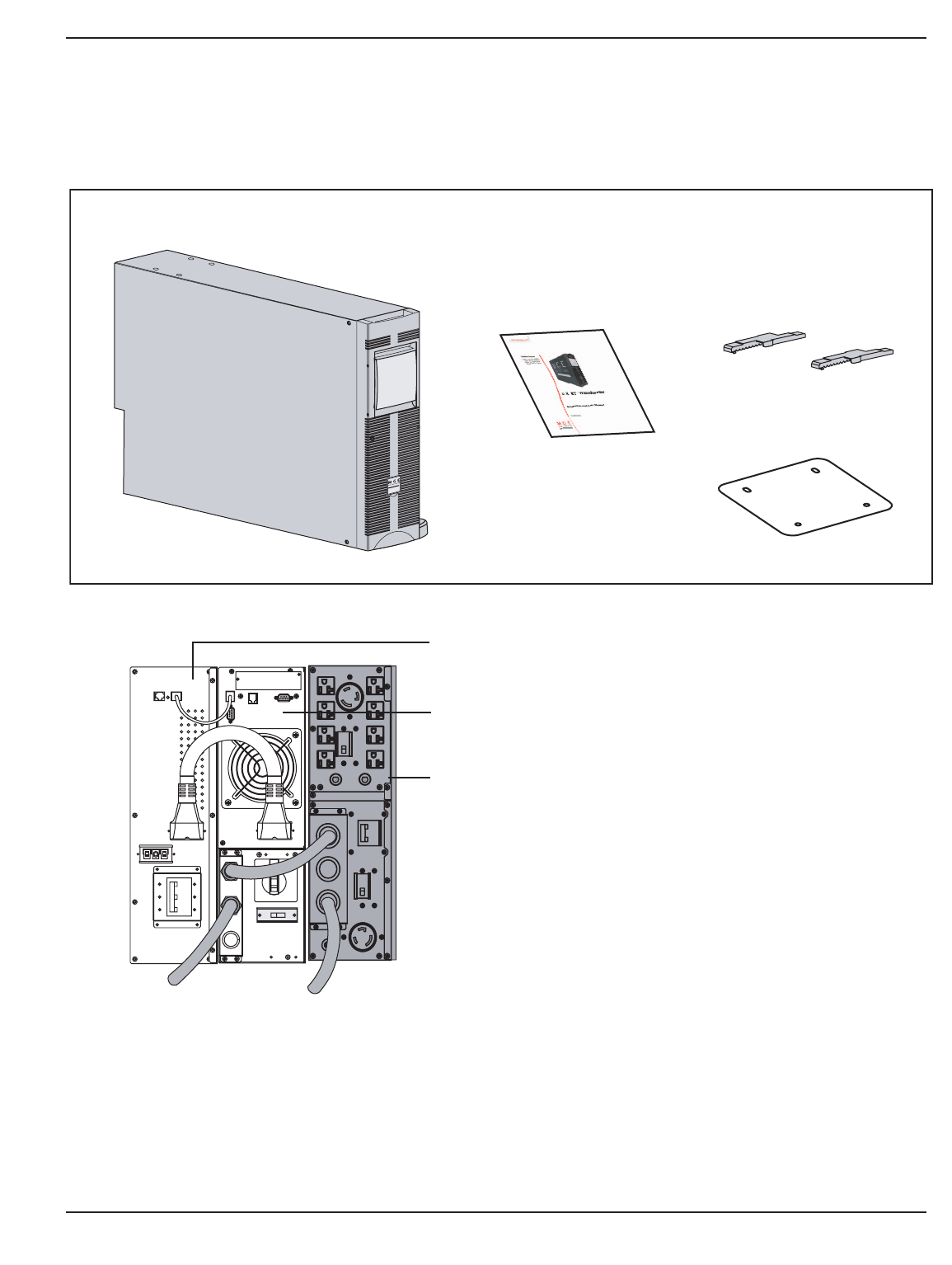
1-3: Rear panel of the Power Module. . . . . . . . . . . . . . . . . . . . . . . . . . . . . . .1 — 6
1-4: Rear Panel of the Battery Module. . . . . . . . . . . . . . . . . . . . . . . . . . . . . .1 — 6
1-5: Rear Panel of the optional Transformer Module. (PN 86003) . . . . . . . . .1 — 7
1-6: View of typical control panel interface. . . . . . . . . . . . . . . . . . . . . . . . . . .1 — 7
1-7: Power Module Rack Mounting Kit. . . . . . . . . . . . . . . . . . . . . . . . . . . . . .1 — 8
1-8: Telescopic rails for the Battery/Transformer/CLA module
Rack mounting. . . . . . . . . . . . . . . . . . . . . . . . . . . . . . . . . . . . . . . . . . . . .1 — 8
1-9: Typical back-up time with multiple EXB’s at full load. . . . . . . . . . . . . . . . .1 — 9
1-10: Typical Battery Integration kit with casters setup. . . . . . . . . . . . . . . . . .1 — 10
1-11: Typical Transformer Module contents and connections. . . . . . . . . . . . .1 — 11
1-12: Connection for CLA Module and EX 5/7/11 RT. . . . . . . . . . . . . . . . . . .1 — 12
2-1: Contents of Standard HV EX 5RT (PN 86050)
/ EX 7RT (PN 86070) / EX 11RT (PN 86110) System. . . . . . . . . . . . . .2 — 3
2-2: Tower Configuration of Standard System and Optional
Transformer Module. . . . . . . . . . . . . . . . . . . . . . . . . . . . . . . . . . . . . . . . .2 — 4
2-3: Typical orientation of the logo and control panel.
(Power Module shown) . . . . . . . . . . . . . . . . . . . . . . . . . . . . . . . . . . . . . .2 — 5
2-4: Accessing Battery Pack. . . . . . . . . . . . . . . . . . . . . . . . . . . . . . . . . . . . . .2 — 6
2-6: Rack mounting of the power module onto the rails. . . . . . . . . . . . . . . . .2 — 7
2-7a: Rear Support Brackets. . . . . . . . . . . . . . . . . . . . . . . . . . . . . . . . . . . . . . .2 — 8
2-7b: Input/Output Box Bracket System. . . . . . . . . . . . . . . . . . . . . . . . . . . . . .2 — 8
2-8: RS232 Communication Cable Connection. . . . . . . . . . . . . . . . . . . . . . . .2 — 9
2-9: Relay Pin Connections for Communication Port. . . . . . . . . . . . . . . . . .2 — 10
2-10: Communication Card Slot with SNMP/Web Network
Management Card installed. . . . . . . . . . . . . . . . . . . . . . . . . . . . . . . . . .2 — 10
2-10a: Activation of remote power off function using a contact
normally open switch. . . . . . . . . . . . . . . . . . . . . . . . . . . . . . . . . . . . . . . .2 — 12
2-10b: Activation of remote power off function using a contact
normally closed switch. . . . . . . . . . . . . . . . . . . . . . . . . . . . . . . . . . . . . .2 — 12
2-12a: Step 1 & 2; Typical plastic and metal coupling installations. . . . . . . . . .2 — 13
2-12b: Step 3; Typical Straight Metal Conduit installation. . . . . . . . . . . . . . . .2 — 14
2-12c: I/O Box Terminal Block Diagram. . . . . . . . . . . . . . . . . . . . . . . . . . . . . . .2 — 14
2-13: Normal AC Input and Output Cables installation. . . . . . . . . . . . . . . . . .2 — 15
2-14: View of EX RT transformer connected downstream for
120/208/240 Vac outputs (shown with one EXB). . . . . . . . . . . . . . . . . .2 — 16
2-15: Normal AC Input, Bypass AC, and Output Cables Installation. . . . . . .2 — 17
2-16: Accessing Terminal Blocks for Input and Output power cables. . . . . . .2 — 18
2-17: Rear view of battery module cable connections. . . . . . . . . . . . . . . . . .2 — 19
2-18: Rear view of CLA module cable battery and AC input connections. . .2 — 20
EX 5/7/11 RT System
Contentsc iv 86-86000-00 A01

Installation and User Manual
Figures (continued)
figure description . . . . . . . . . . . . . . . . . . . . . . . . . . . . . . . . . . . . . . . . . . . . . . . . .page
3-1: Initial Startup Display. . . . . . . . . . . . . . . . . . . . . . . . . . . . . . . . . . . . . . . .3 — 1
3-2: Control Panel with scroll up and down buttons. . . . . . . . . . . . . . . . . . . .3 — 2
3-3: Configuration used to provide full redundancy (2N) to critical loads. . . .3 — 3
3-4: Normal (double conversion) mode. . . . . . . . . . . . . . . . . . . . . . . . . . . . . .3 — 5
3-5: ECO mode display. . . . . . . . . . . . . . . . . . . . . . . . . . . . . . . . . . . . . . . . . .3 — 6
3-6: Transfer, Threshold and End of backup time. . . . . . . . . . . . . . . . . . . . . .3 — 7
3-7: Shutdown display, circuit breaker, and AC source switch. . . . . . . . . . . .3 — 8
4-1: Disconnecting the power module. . . . . . . . . . . . . . . . . . . . . . . . . . . . . . .4 — 4
4-2: Reconnect the power module. . . . . . . . . . . . . . . . . . . . . . . . . . . . . . . . . .4 — 5
4-3: Rear view of the battery module. . . . . . . . . . . . . . . . . . . . . . . . . . . . . . .4 — 6
5-1: Power supplied as a function of input voltage (left), and
Permissible UPS overloads as a function of time (right). . . . . . . . . . . . . .5— 1
Tables
table description . . . . . . . . . . . . . . . . . . . . . . . . . . . . . . . . . . . . . . . . . . . . . . . . .page
1: EX RT Model Descriptions and Contents . . . . . . . . . . . . . . . . . . . . . . . .1 — 2
2: Optional Accessories (See section 1.5 for description) . . . . . . . . . . . . .1 — 3
3: Power Module Ratings . . . . . . . . . . . . . . . . . . . . . . . . . . . . . . . . . . . . . .1 — 4
4: Battery Module Ratings . . . . . . . . . . . . . . . . . . . . . . . . . . . . . . . . . . . . .1 — 4
5: Battery backup time chart. . . . . . . . . . . . . . . . . . . . . . . . . . . . . . . . . . .1 — 12
3-1: Local Settings. . . . . . . . . . . . . . . . . . . . . . . . . . . . . . . . . . . . . . . . . . . . . .3 — 3
3-2: Output features. . . . . . . . . . . . . . . . . . . . . . . . . . . . . . . . . . . . . . . . . . . . .3 — 3
3-3: ON/OFF features. . . . . . . . . . . . . . . . . . . . . . . . . . . . . . . . . . . . . . . . . . .3 — 4
3-4: Battery features. . . . . . . . . . . . . . . . . . . . . . . . . . . . . . . . . . . . . . . . . . . .3 — 4
4-1: Network and Industrial Modes of Operation. . . . . . . . . . . . . . . . . . . . . . .4 — 1
4-2: Troubleshooting not requiring MGE after-sales support. . . . . . . . . . . . . .4 — 2
4-3: Troubleshooting requiring MGE after-sales support. . . . . . . . . . . . . . . . .4 — 3
5-1: EX 5/7/11 RT Input and Output Characteristics. . . . . . . . . . . . . . . . . . . .5 — 1
5-2: Back-up Time ( in minutes). . . . . . . . . . . . . . . . . . . . . . . . . . . . . . . . . . . .5 — 1
5-3: Battery Recharge time to recover 90% of the rated backup time
after discharge at full load. . . . . . . . . . . . . . . . . . . . . . . . . . . . . . . . . . . .5 — 2
5-4: Full load heat rejection in BTU’s/hr. . . . . . . . . . . . . . . . . . . . . . . . . . . . . .5 — 2
Contents c v86-86000-00 A01

(This page left blank intentionally)
EX 5/7/11 RT System
c vi 86-86000-00 A01

Introduction
1.0 Scope
Thank you for selecting an MGE UPS SYSTEMS, INC. (MGE) product to protect your electrical equipment.
The product you selected is a part of the EX RT series. The EX RT series is a family of Uninterruptible Power Supply
(UPS) designed to provide safe, and reliable AC power backup for sensitive electrical equipment. To discover the
entire range of MGE products, we invite you to visit our website at www.mgeups.com or contact your representative
at (800) 523-0142.
This manual describes the installation and operation of standard HV EX 5/7/11RT systems within the EX RT product
family. For a complete description of the EX RT product family and its available options, please refer to the tables
below:
1 Introduction
Introduction is a general description of system configurations of the EX 5/7/11 RT, and its mechanical
,electrical characteristics. Additionally there is an optional accessories section with important information on MGE
products that will enhance the performance of the EX 5/7/11RT. Please contact your MGE representative for
detailed information on these options.
2 Setup and Installation
Setup and Installation guides the user through tools and equipment required for connecting the EX 5/7/11 RT and
battery installation or replacement. Included are assembly instructions, power cable connections with wire diagrams
for configuring the product to hardware specifications.
3 Operation
Operation describes the EX 5/7/11RT system characteristics of indicators and controls, modes and specifications.
The user procedures include performing software programming that will maintain optimal performance.
4 Maintenance
Maintenance includes a troubleshooting guide of symptoms and possible solutions, hot swapping the power module,
battery module, and testing scenarios.
5 Appendix
Electrical and Mechanical specifications for the EX 5/7/11 RT.
A Glossary provides definitions of abbreviations and terms used in this manual.
1 — 186-86000-00 A01 Introduction

Table 1: EX RT Model Descriptions and Contents
System Description Contents
Model Part Power Module Battery Module Transformer Power Module Battery Module SNMP/Web
Number 86055 86075 86115 86079 86119 Module Rail Kit 86001 Rail Kit 86002 Network
(120/208/240Vac) Mgt. Card
86003 66074
5kVA 86050 X X
HV EX 5RT
5kVA 86052 X X X X X
HV EX 5RT
Network Pack
5kVA 86050-01 X X X
LV EX 5RT
5kVA 86052-01 X X X X X (x2) X
LV EX 5RT
Network Pack
7kVA 86070 X X
HV EX 7RT
7kVA 86072 X X X X X
HV EX 7RT
Network Pack
7kVA 86070-01 X X X
LV EX 7RT
7kVA 86072-01 X X X X X (x2) X
LV EX 7RT
Network Pack
11kVA 86110 X X
HV EX 11RT
11kVA 86112 X X X X X
HV EX 11RT
Network Pack
11kVA 86110-01 X X X
LV EX 11RT
11kVA 86112-01 X X X X X (x2) X
LV EX 11RT
Network Pack
EX 5/7/11 RT System
Introduction1 — 2 86-86000-00 A01

Installation and User Manual
Table 2: Optional Accessories (See section 1.5 for description)
Part Number Description
86001 Rail Kit for Power Module EX 5/7/11 RT
86002 Rail Kit for Battery/Transformer/CLA Module
86005 Battery Integration Kit with Casters
86006 Battery Extension Cable Kit
86008 Battery Chassis Empty EXB RT W/EPO
86009 I/O Box 5/7kVA UL/US
86010 I/O Box 11kVA UL/US
86012 I/O Box Bracket System
86013 Rear Bracket Supports
Introduction 1 — 386-86000-00 A01
1.1 System Electrical Characteristics
Table 3: Power Module Ratings
Part Number 86055 86075 86115
Apparent Power, kVA 5 7 10@ 200/208/250 VAC Output
11@ 220/230/240 VAC Output
Active Power, kW 4 4.9 8@ 200/208/250 VAC Output
7.3@ 220/230/240 VAC Output
Input Current, A 25/24/23/ 35/34/32 50/48/50/48/46/40
22/21/20 31/30/28
Input Voltage, VAC 200/208/220/ 200/208/220/ 200/208/220/230/240/250
230/240/250 230/240/250
Output Current, A 25/24/23/ 35/34/32 50/48/50/48/46/40
22/21/20 31/30/28
Output Voltage, VAC 200/208/220/ 200/208/220/ 200/208/220/230/240/250
230/240/250 230/240/250
CAUTION Power Module is factory configured at 208Vac, 60 Hz input and output.
Input and Output of the UPS must always be the same.
Table 4: Battery Module Ratings
Part Number 86079 86119
Battery Type 12VDC/7Ah 12VDC/9Ah
Battery Output Voltage 240VDC 240VDC
1.2 Standard Configurations
The EX 5/7/11 RT systems can be set up in tower and rack configurations.
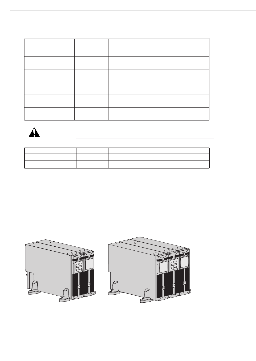
1.2.1 Tower Configuration
Figure 1-1: Tower Configurations with Power Module, Battery Module, and optional Transformer Module.
EX 5/7/11 RT System
Introduction1 — 4 86-86000-00 A01
www.mgeups.comwww.mgeups.com
E X B R T
E X 1 1 R T
OFFON
BATTERY MODULE
(EXB 5/7/11 RT)
POWER MODULE
(EX 5/7/11 RT)
www.mgeups.comwww.mgeups.com
OFFON
BATTERY MODULE
POWER
MODULE
EX 11 RT EXB RT
EX RT Transformer
EX RT Transformer
www.mgeups.c
om
Standard Configuration Configuration with Transformer
Installation and User Manual
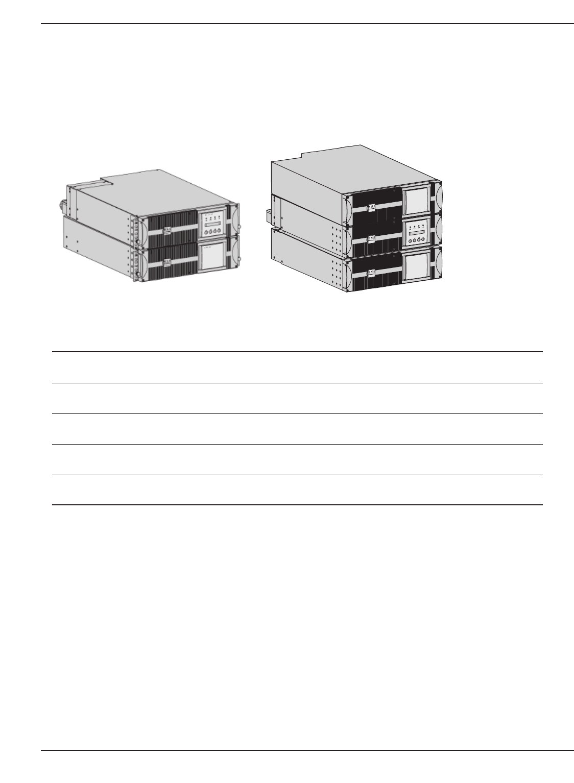
1.2.2 Rack Configuration
Figure 1-2: Rack Configurations with Power Module, Battery Module, and Transformer Module.
Introduction 1 — 586-86000-00 A01
Model Dimensions Weights
EX 5RT/7RT (3U) 5.16” x 17.49” x 25” 49.6 lbs (22.5 kg)
(131 x 444 x 635mm)
EX 11RT (3U) 5.16” x 17.49” x 25” 60.6 lbs (27.6 kg)
(131 x 444 x 635mm)
EXB 5 RT/ 7 RT (3U) 5.16” x 17.49” x 25” 142 lbs (64.5 kg)
(131 x 444 x 635mm)
EXB 11RT (3U) 5.16” x 17.49” x 25” 151 lbs (68.5 kg)
(131 x 444 x 635mm)
EX RT (3U) 5.16” x 17.49” x 25” 173 lbs (78.5 kg)
Transformer (131 x 444 x 635mm)
POWER MODULE
(EX 5/7/11 RT)
BATTERY MODULE
(EXB 5/7/11 RT)
www.mgeups.com
www.mgeups.com
OFFON
EX 11 RT
EXB RT
www.mgeups.com
EX RT Tran sformer
POWER MODULE
(EX 5/7/11 RT)
BATTERY MODULE
(EXB 5/7/11 RT)
EX RT Transformer
Standard Configuration Configuration with Transformer
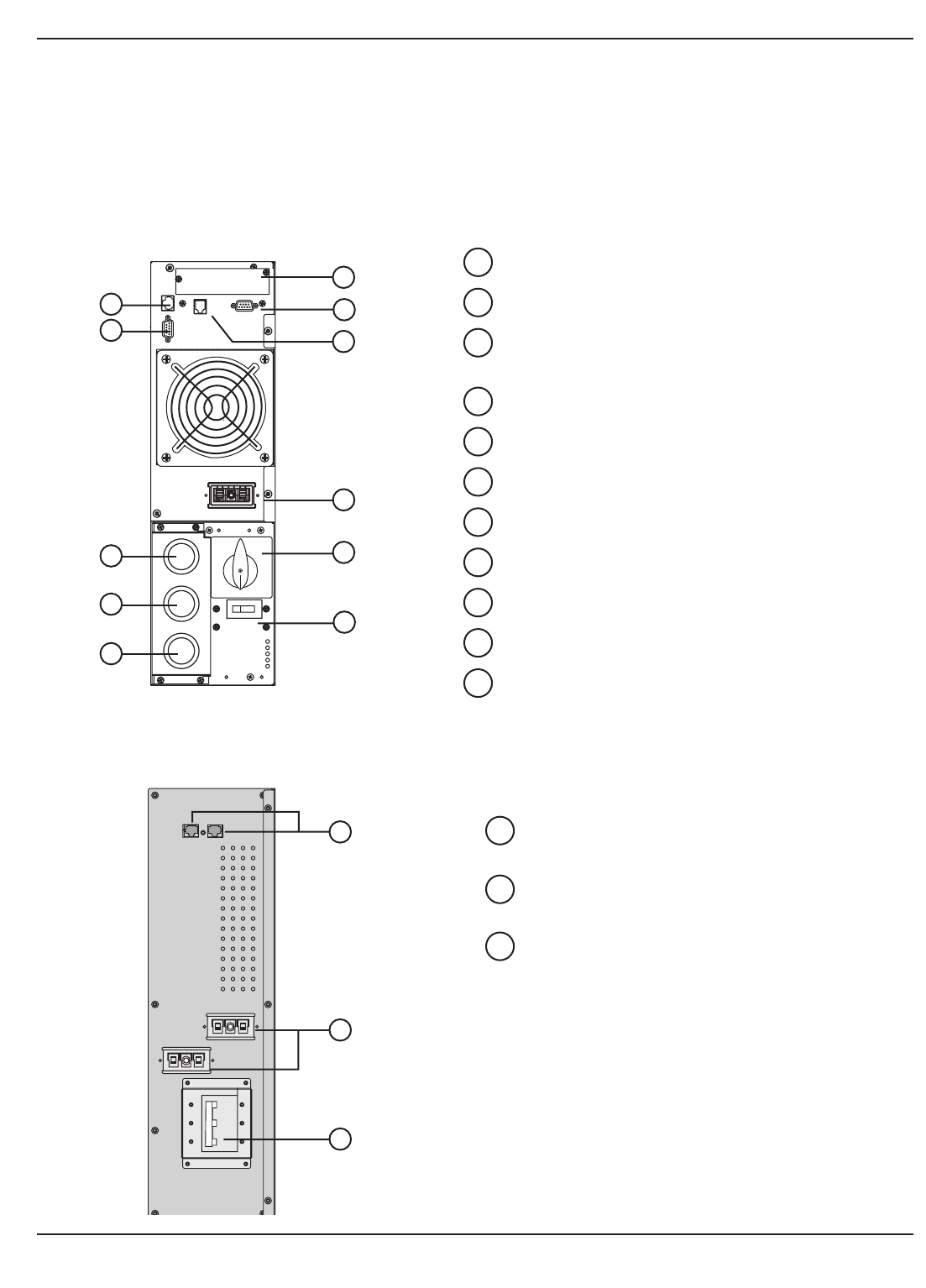
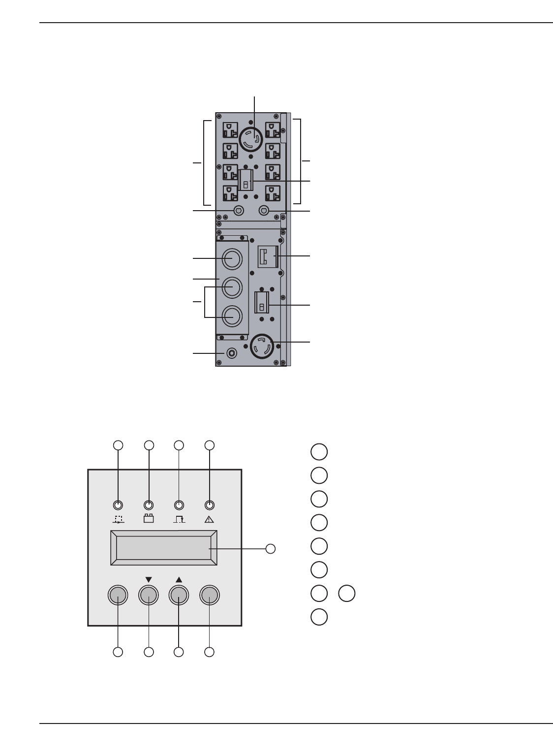
1.3 Rear Panels
1.3.1 Power Module EX 5/7/11 RT
EX 5RT Power Module part number 86055
EX 7RT Power Module part number 86075
EX 11RT Power Module part number 86115
Figure 1-3: Rear panel of the Power Module.
1.3.2 Battery Module EXB 5/7/11 RT With Emergency Power Off (EPO) Function
Figure 1-4: Rear Panel of the Battery Module.
EX 5/7/11 RT System
Introduction1 — 6 86-86000-00 A01
13
12
14
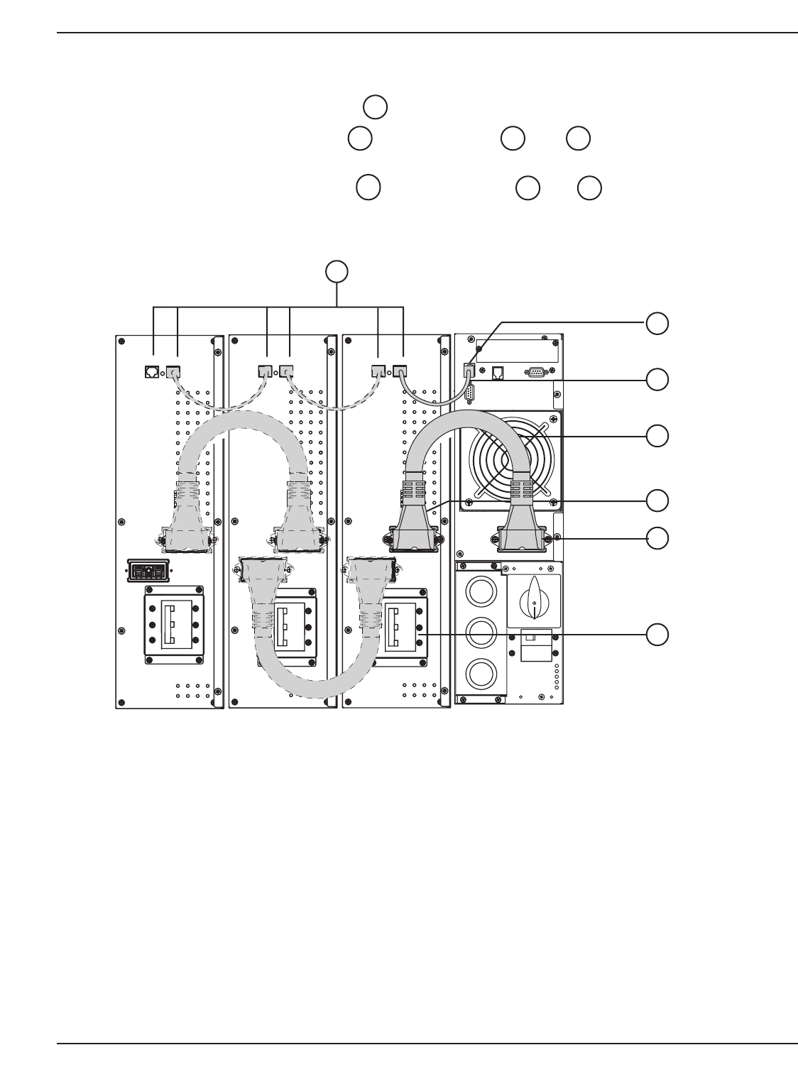
Connectors for automatic detection of additional battery
module(s) (to the UPS or to other battery modules).
Battery power connectors (to the UPS or to other
battery modules).
Battery Circuit Breaker with Remote Emergency Power
Off (REPO) shunt trip.
EXB 5RT with EPO part number 86079
EXB 7RT with EPO part number 86079
EXB 11RT with EPO part number 86119
14
13
12
1
2
4
53
6
7
9
10
11
8
Slot for optional communication cards.
Communication port by relays (Dry contacts).
Remote Emergency Power Off communication port
(REPO).
Connectors for automatic detection of battery module(s).
RS232 communication port.
Battery/CLA module power connector.
Manual Bypass switch.
Normal AC source circuit breaker.
Knockout for entry of AC Output conduit.
Knockout for entry of Normal AC source conduit.
Knockout for entry of Bypass AC source conduit.
11
10
9
8
7
6
5
4
3
2
1
Installation and User Manual
1.3.3 EX RT Transformer Module
Figure 1-5: Rear Panel of the optional Transformer Module. (PN 86003)
1.4 Display and Control Panel
Figure 1-6: View of typical control panel interface.
Introduction 1 — 786-86000-00 A01
Main Output Circuit Breaker
Load 2: 4 NEMA 5-15/20R
Load 3 Circuit Breaker
Load 2 Circuit Breaker
Load 1: 1 NEMA L6-30R
Load 1 Circuit Breaker
Transformer Protect
Breaker
Load 4: 4 NEMA 5-15/20R
Load 4 Circuit Breaker
Transformer I/O Box
AC Input
AC Output
L
oa
d
3: 1
NEMA
L
6-30
R
OFF ON
E X 1 1 R T
15 16
19
17 18
20 21 22 23
Load protected / On-line Operation LED.
Operation on battery LED.
Operation on bypass LED.
Fault LED.
Alphanumeric display.
UPS OFF button.
Function buttons (scroll up / scroll down).
UPS ON button (or function button in personalization
mode).
23
2221
20
19
18
17
16
15
1.5 Optional Accessories
Optional Accessories describes the options available for upgrades and enhancement of the EX 5/7/11RT system.
Detailed installation of the unit is described in following sections.
To ensure a successful installation, all procedures should be followed in their correct sequence. Note that any
unauthorized installation may cause damage to the UPS(s) and void the MGE warranty.
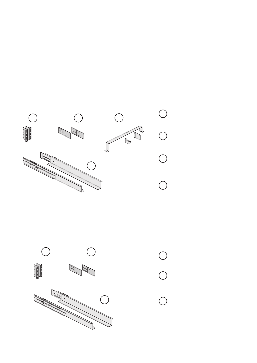
1.5.1 Power Module Rail Kit
(Part Number 86001)
This kit is for rack mounting the power module in a 19" enclosure. See section 2.6 for rack installation of power
module.
Figure 1-7: Power Module Rack Mounting Kit.
Front mounting brackets.
Rear support brackets, part number
86013.
Telescopic rails, 695 mm to 1015 mm
length (27.36" to 39.96").
Input/Output Box bracket system, part
number 86012.
1.5.2 Battery/ Transformer/CLA Module Rail Kit
(Part number 86002)
This kit is for rack mounting of the battery/step-down transformer/CLA module in 19" enclosure. See section 2.6 for
rack installation of power module.
Figure 1-8: Telescopic rails for the Battery/Transformer/CLA module Rack mounting.
Front mounting brackets.
Rear support brackets, part number
86013.
Telescopic rails, 695 mm to 1015 mm
length (27.36" to 39.96").
26
25
24
27
26
25
24
EX 5/7/11 RT System
Introduction1 — 8 86-86000-00 A01
24 25
26
27
24 25
26
Installation and User Manual
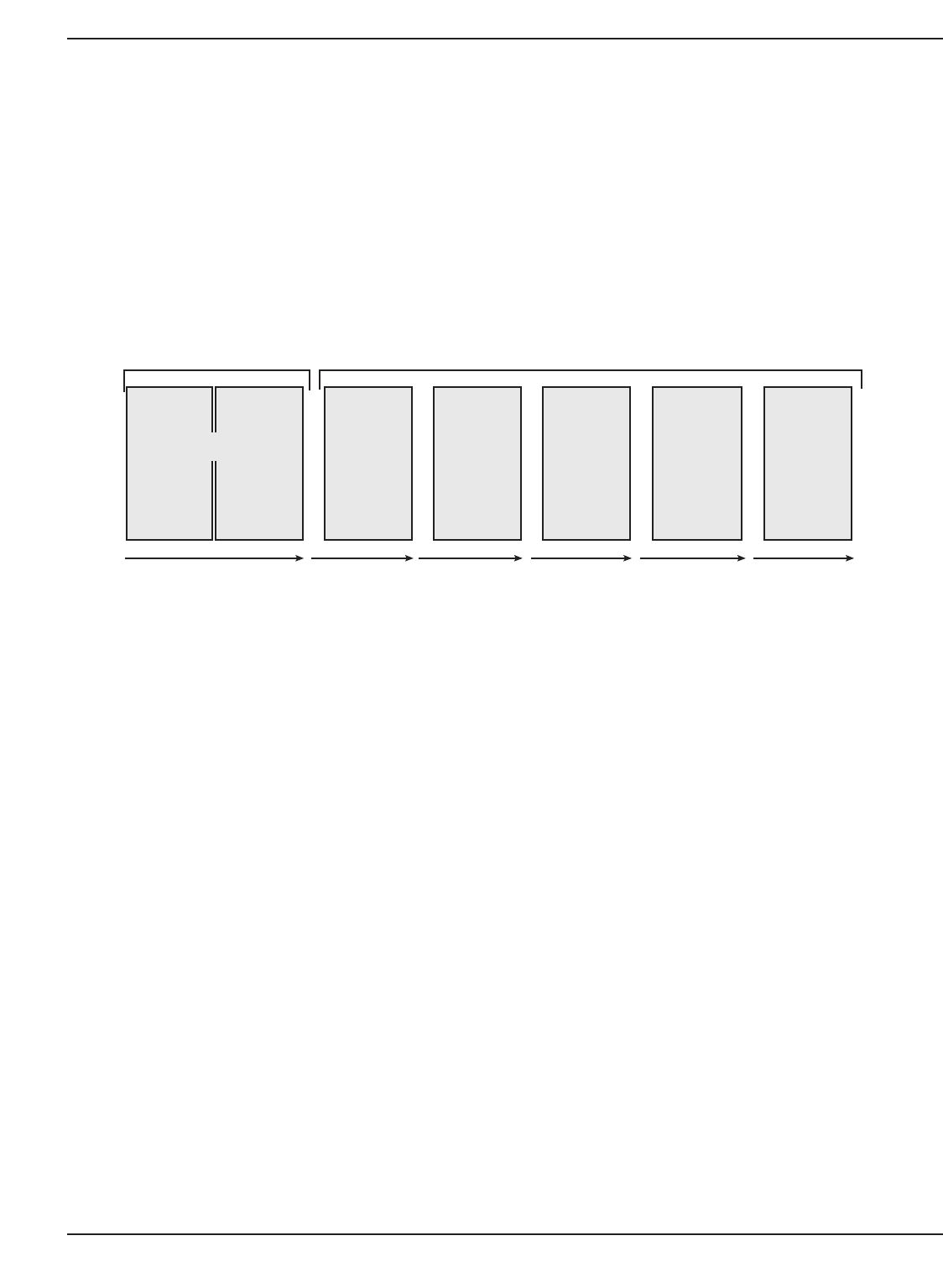
1.5.3 Battery Module with Remote Emergency Power Off (REPO) Function
(EXB 5/7 RT; PN 86079, EXB 11RT; PN 86119)
Standard HV EX 5/7/11RT system (one Power Module, EX 5/7/11 RT, and one Battery Module, EXB 5/7/11RT)
offers a standard backup time of 5 to 12 minutes at full load.
To increase backup time, it is possible to connect up to 5 additional EXB 5/7/11 RT modules to the EX 5/7/11 RT
module. See section 2.10 for connections between Power Module (EX 5/7/11 RT) and Battery Module (EXB 5/7/11
RT)
Figure 1-9: Typical back-up time with multiple EXB’s at full load.
See Appendix for additional Back-up time information.
1.5.4 Battery Extension Cable Kit
( 6 ft / 1.8 m, Part number 86006)
This extended battery cable kit will be used instead of the standard battery cable when battery modules (EXBs) are
distant from each other (located in two different enclosures, for instance).
The battery extension cable kit includes a 6 ft long, straight connector battery power cable and a 6 ft. long battery
detection cable.
Introduction 1 — 986-86000-00 A01
+++
EXB 5 RT
/
EXB 11 RT
7 kVA :
11 kVA:
7 min
5 min
20 min
14 min
32 min
22 min
+ +
45 min
30 min
57 min
42 min
70 min
53 min
EXB 5 RT
/
EXB 11 RT
EXB 5 RT
/
EXB 11 RT
EXB 5 RT
/
EXB 11 RT
EXB 5 RT
/
EXB 11 RT
EXB 7 RT EXB 7 RT EXB 7 RT EXB 7 RT EXB 7 RT
Standard
HV EX 5/7/11RT system
O
pt
i
ona
l
Configurations
5 kVA : 12 min 30 min 55 min 75 min 98 min 118 min
EX 5/7/11RT EXB 5/7/11RT
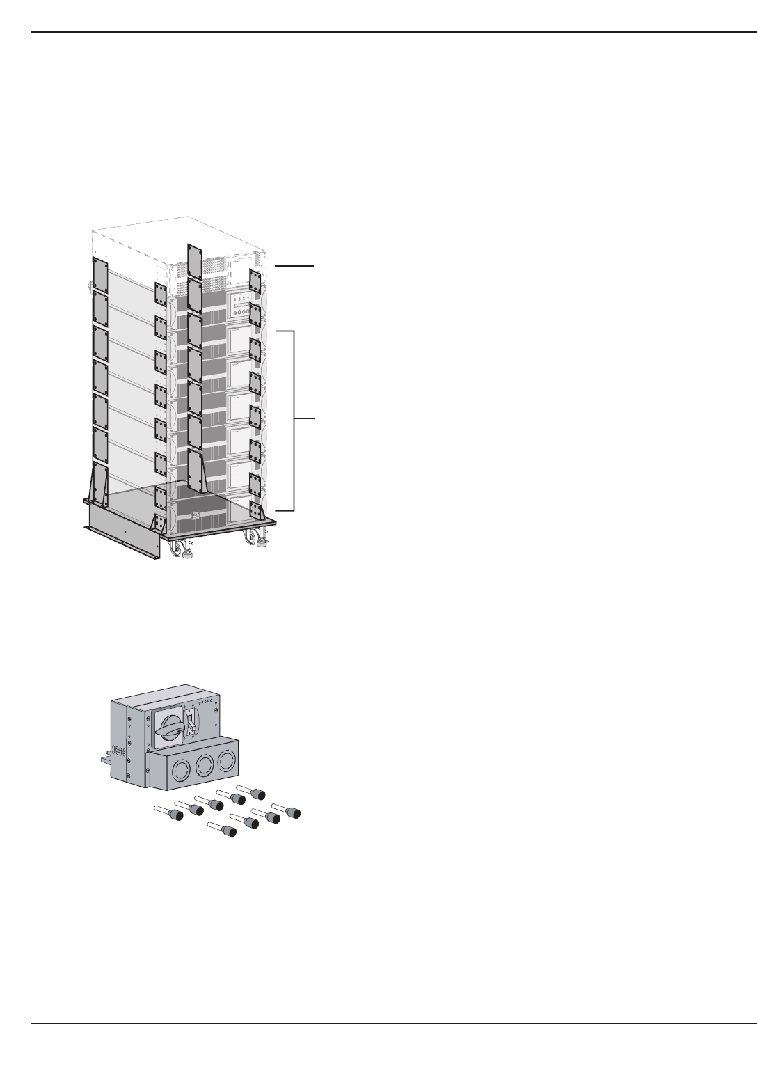
1.5.5 Battery Integration Kit with Casters
(Part number 86005)
Battery Integration Kit is a cart, designed to hold up to 8 modules. It has swivel wheels with brakes, leveling feet,
seismic floor mount panels, plates to lock modules and hardware included. Modules not included.
Figure 1-10: Typical Battery Integration kit with casters setup.
1.5.6 Input/Output Box
Shipped with ferrules for stranded wire application.
EX 5/7/11 RT System
Introduction1 — 10 86-86000-00 A01
TRANSFORMER MODULE
(optional)
POWER MODULE
BATTERY MODULES
(up to 6)
(Modules Not Included In Kit)
- I/O Box 5/7kVA Part number 86009
- I/O Box 11kVA Part number 86010
OFF
O
Installation and User Manual
1.5.7 Transformer Module
This module provides isolated 120/208/240Vac output.
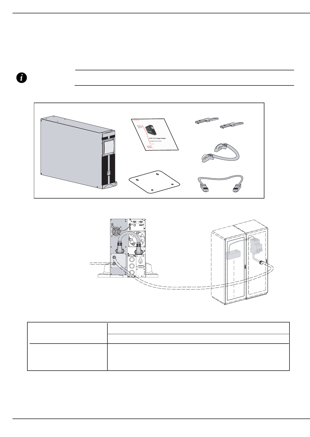
Figure 1-12: Typical Transformer Module contents and connections.
1 — 1186-86000-00 A01 Introduction
www.mgeups.com
E X R T Transformer
EX RT Transformer Module Contents
Tower Stand Expanders
Transformer User Manual
BATTERY MODULE
EXB RT
POWER MODULE
EX 5/7/11 RT
TRANSFORMER
MODULE EX RT
AC NORMAL
INPUT
STEP-DOWN
TRANSFORMER
OUTPUT TO LOAD
Stabilizer Bracket
(4 screws included)
1.5.8 CLA Module (Long backup time charger)
(Part number 86004)
Extended back-up time (up to 8 hours at full load) requires a high power battery cabinet connected to the EX
5/7/11RT via the CLA module.
IMPORTANT The CLA can not be used to charge the battery module (EXB). It is designed to charge the
customer provided high power battery cabinet.
Figure 1-12: Connection for CLA Module and EX 5/7/11 RT.
Table 5: Battery backup time chart.
Battery Backup Time Recommended Batteries
EX 5RT EX 7RT EX 11RT
2 hours 50 Ah 65 Ah 100 Ah
4 hours 100 Ah 130 Ah 200 Ah
8 hours 200 Ah 200 Ah 400 Ah
Total battery voltage : 240 VDC (20 x 12VDC, one string).
The battery capacity must be set within the UPS (5 Ah increment possible, see UPS Personalization section 3.2.
EX 5/7/11 RT System
Introduction1 — 12 86-86000-00 A01
EX 5RT /
EX 7RT /
EX 11RT
~
50A
(cable not included)
Typical High Power
Battery Cabinet
(not included)
Utility
AC Source
(cable not included)
(see section 2.10 for cable
connection information)
www.mgeups.com
E X R T Transformer
CLA Module Contents
CLA
Tower Stand ExpandersCLA Documentation
Battery Detection Cable
Battery Power Cable
Stabilizer Bracket
(4 screws included)

Setup and Installation
2.0 Scope
Installation guides the user through tools and equipment required for making input/output power and communica-
tion cable connections, and battery installation and replacement. It provides assembly instructions, power cable
connections with wire diagrams for configuring the product to hardware specifications.
2.1 Unpacking and Parts Check
Once the EX 5/7/11RT system has been inspected and received from the shipping courier, the unit should be moved
to a position as close to the final installation location as possible. See Figures 2-1on page 2-3.
All Modules are shipped in separate boxes.
Prior to any installation, the following items should be observed upon receipt of the EX 5/7/11 RT.
1. Inspect shipment for any damage prior to receipt. Damage claims should be filed directly with the courier.
Replacements for damaged components should be ordered through MGE Customer Support Services at
1-800-438-7373.
2. Remove wrapping and foam corners to verify that the equipment nameplate (located on the rear of the units)
details a system that corresponds with the equipment ordered.
2 — 186-86000-00 A01 Installation
EX 5/7/11 RT System
2 — 2 86-86000-00 A01
2.2 Contents of EX 5/7/11 RT System
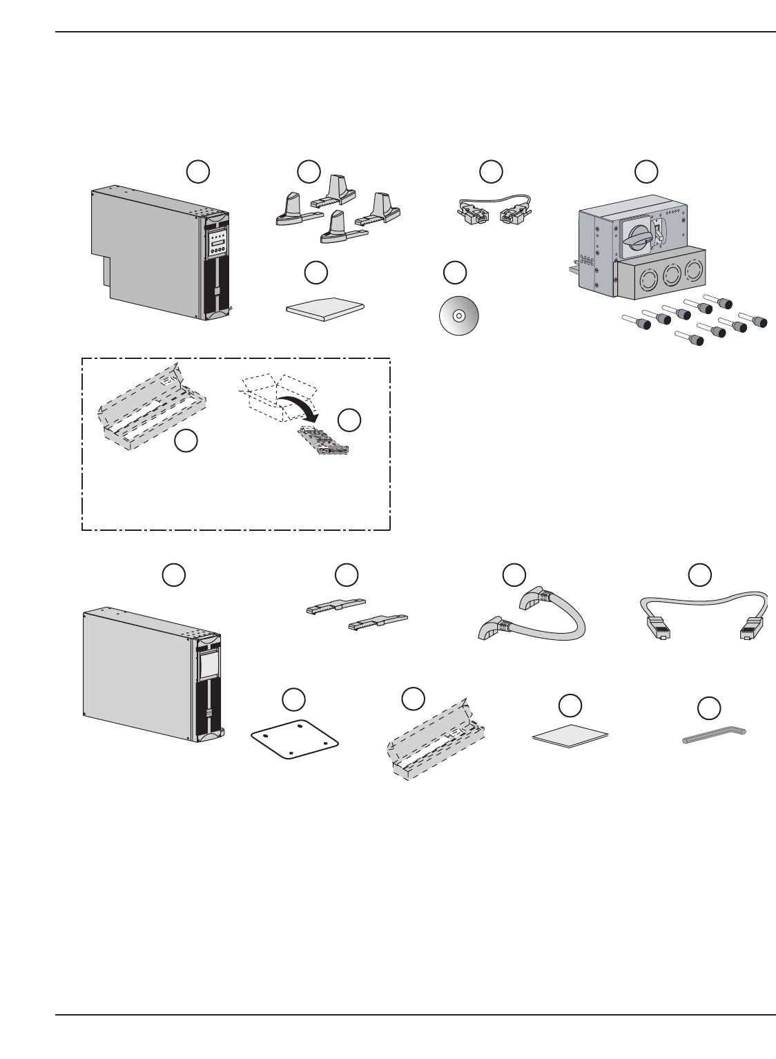
Contents of Power Module:Contents of Battery Module:
EX 5RT /EX 7RT/ EX 11RT. Stabilizer Bracket and hardware.
Two sets of tower stands. EXB 5/7/11 RT.
RS232 communication cable. Tower stand expanders.
Product documentation. Battery Power cable.
Input/Output Box. (With 9 insulated ferrules for Battery/EX RT transformer/CLA
stranded wires.) module rack mounting kit, PN 86002.
(PN 86009 for EX 5/7RT; 86010 for EX 11RT)
Battery detection cable.
Solution-Pac CD. EXB Documentation.
Power Module rack mounting kit, PN 86001 Bezel hex drive.
(optional, but standard with Network Pack version).
SNMP/Web Network Management Card, PN 66074.
(optional, or standard with Network Pack version)
IMPORTANT Packaging must be destroyed according to waste management standards.
Recycling icons are displayed for easy selection.
37
4436
4335
42
4134
4033
3932
3831
2930
Installation
Installation and User Manual
Figure 2-1: Contents of Standard HV EX 5RT (PN 86050) / EX 7RT (PN 86070) / EX 11RT (PN 86110) System.
Installation 2 — 386-86000-00 A01
Card Settings
RS232 Download 66074
UPS
data
Reset
100 10
1 2
ON
ETHERNET RS232
IP=
MAC=00E0D8FF855E
E X 1 1 R T
31 32
33
34
35
36 (see 1.5.1)
37
Standard only with Network Pack option.
- EX 5RT network Pack Part number 86052-01
- EX 7RT network Pack Part number 86072-01
- EX 11RT network Pack Part number 86112-01
- EX 5RT Power Module Part number 86055
- EX 7RT Power Module Part number 86075
- EX 11RT Power Module Part number 86115
E X B R T
39 40 42
41 43 44
(not to scale)
Standard only with
Network Pack version.
See 1.5.2.
- EXB 5RT Battery Module Part number 86079
- EXB 7RT Battery Module Part number 86079
- EXB 11RT Battery Module Part number 86119
OFF
O
30
38
29
- I/O Box 5/7kVA Part number 86009
- I/O Box 11kVA Part number 86010
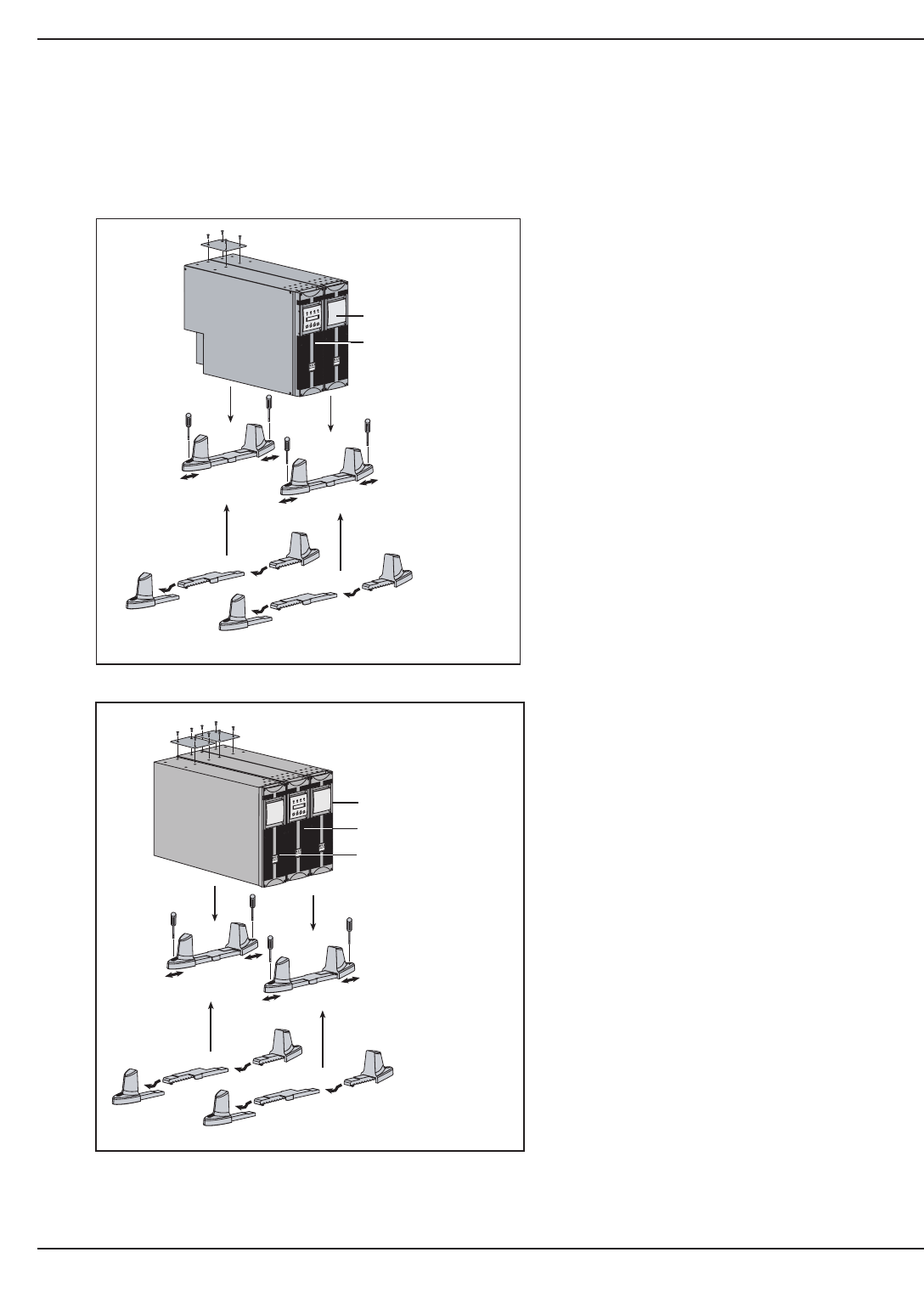
2.3 Installation in Tower Configuration
Follow the numerical sequence to assemble tower stands and tower stand expanders, shown in Figure 2-2.
Figure 2-2: Tower Configuration of Standard System and Optional Transformer Module.
EX 5/7/11 RT System
Installation2 — 4 86-86000-00 A01
www.mgeups.comwww.mgeups.com
E X B R T
E X 1 1 R T
OFFON
www.mgeups.com
Tower Configuration with Optional Transformer Module
Tower Configuration with Standard System
Use the same procedure
for tower mounting multiple
battery modules, if applicable.
www.mgeups.comwww.mgeups.com
E X B R T
E X 1 1 R T
OFFON
Transformer Module
Battery Modules
Power Module
Battery Module
1
1
2
2
4
4
4
4
33
5
1
1
2
2
4
4
4
4
33
5
Power Module
Installation and User Manual
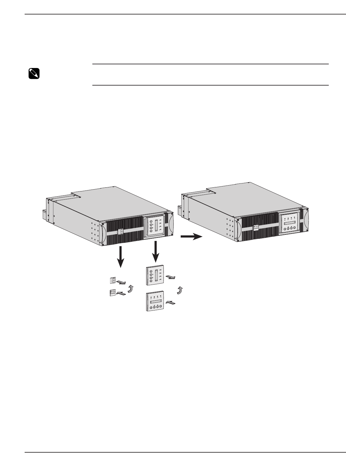
2.4 Installation in Rack Mounting Configuration
2.4.1 Adjustment of Front Panel Logo and control panel for Rack Orientation.
NOTE If system includes the transformer module, we recommend to mount the battery module
on the bottom, then mount the power module above the battery module and mount the
transformer on top for optimum stability.
To prepare the front panel logo and LCD display for rack orientation, of all modules. (including transformer or CLA
module, if equipped).
Proceed as follows:
1. Unclip logo plate, and pull the LCD display from front panel.
2. Rotate them 90 degree counter clockwise as shown.
3. Place items back onto the panel.
Figure 2-3: Typical orientation of the logo and control panel. (Power Module shown)
Installation 2 — 586-86000-00 A01
www.mgeups.com
E X 1 1 R T
OFFON
E X 1 1 R T
OFFON
www.mgeups.com
www.mgeups.com
E X 1 1 R T
OFFON
E X 1 1 R T
OFFON
www.mgeups.com
1
2
3
FINISHED PANEL
(rack orientation)
1
2
3
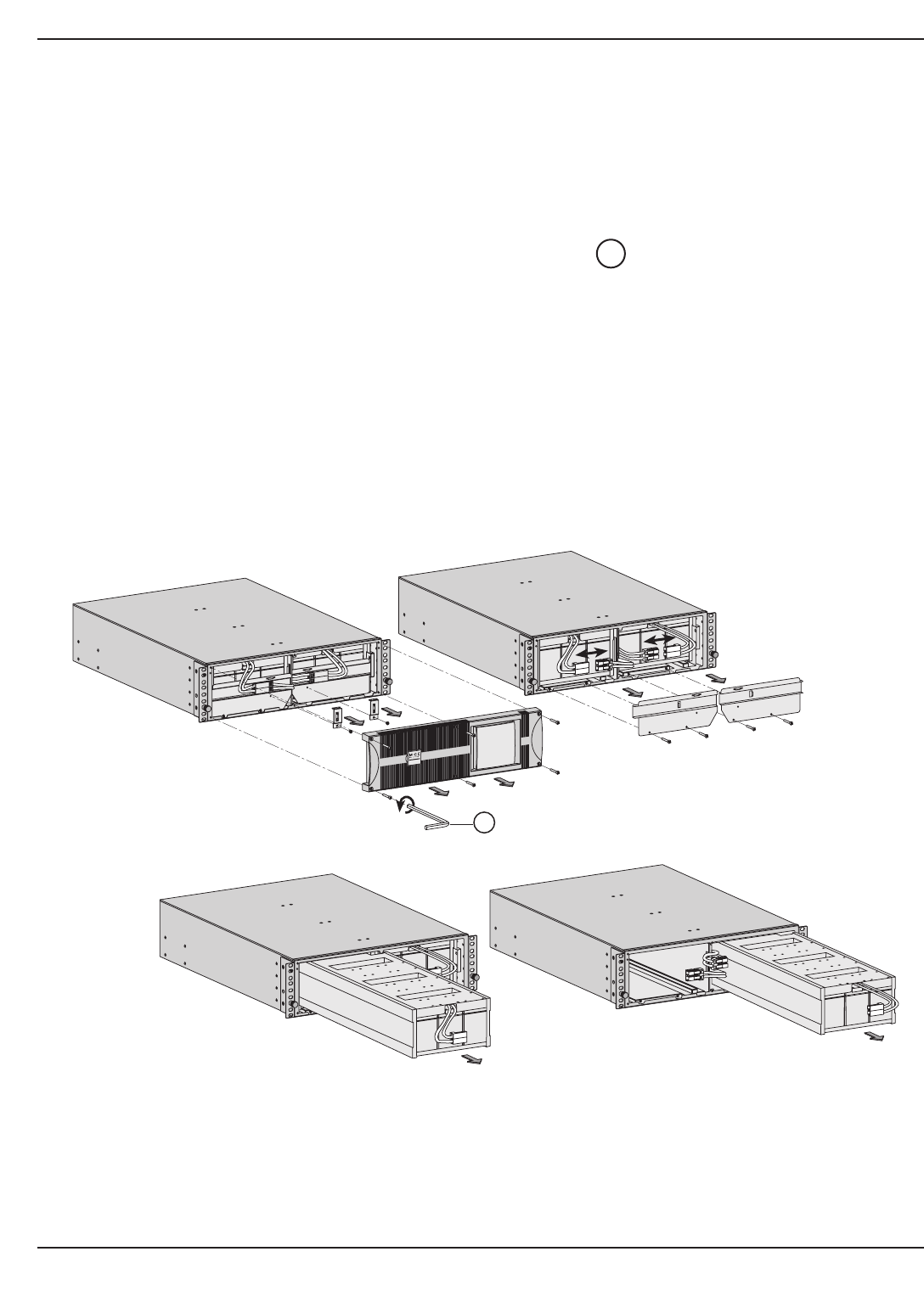
2.5 Prepare Battery Module for Rack Mounting
(optional rails required, part number: 86002)
The battery module is very heavy. To ease its rack mounting, we strongly recommend to remove the battery pack
from the battery module, as explained below. See Section 1.2.2 for battery module weight.
Proceed as follows:
1. Unscrew the six screws securing front panel using Bezel Hex Driver .
2. Unscrew the brackets securing the battery connectors.
3. Disconnect Battery plugs.
4. Unscrew the brackets securing the battery pack. Remove battery bracket pack covers.
5. Pull the left and right battery packs out and set aside for reinstalling after the battery module cabinet has been
rack mounted.
6. Mount battery module cabinet on rack.
7. Re-install the battery pack in reverse order.
Figure 2-4: Accessing Battery Pack.
44
EX 5/7/11 RT System
Installation2 — 6 86-86000-00 A01
E X B R T
x 6
www.mgeups.com
1
11
2
2
33
44
44
(not to scale)
5
Installation and User Manual
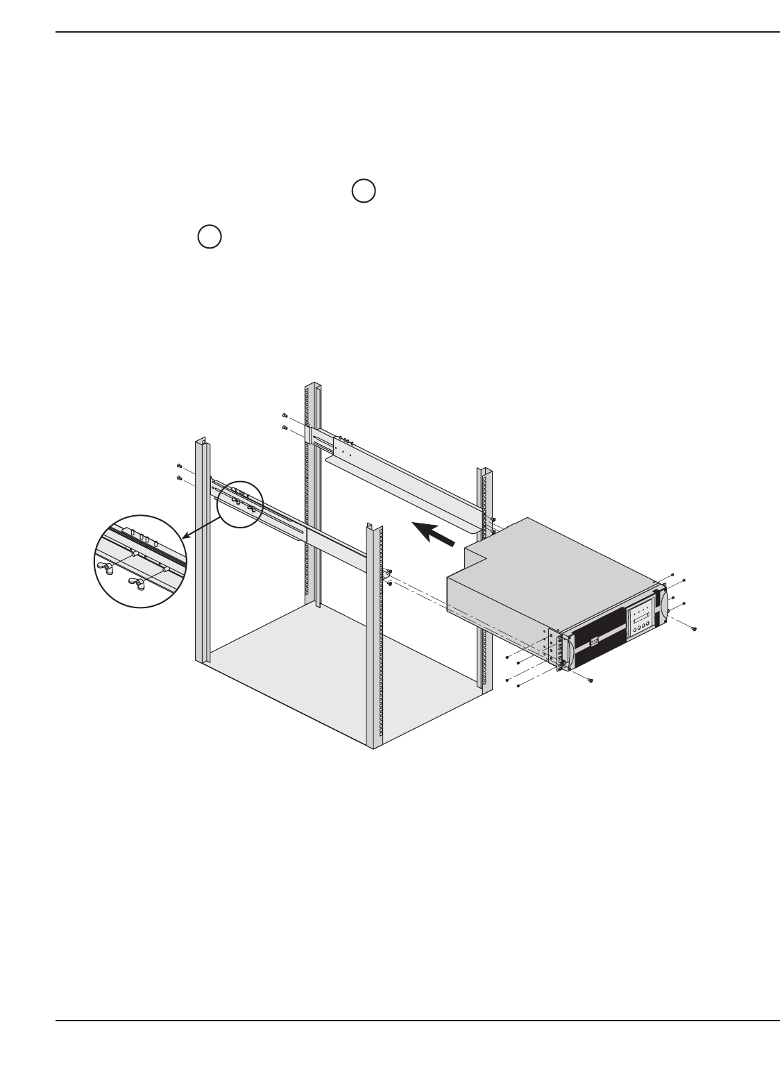
2.6 Power or Battery Module Rack Mounting
(optional rack mounting kits required, part number: 86001 and 86002)
The rails and necessary mounting hardware are supplied by MGE UPS SYSTEMS, INC.
Proceed as follows:
1. Attach both front mounting ear brackets to power module or battery module with supplied screws. (For this
step, it is possible to adjust the position of both front mounting ears.)
2. Attach rails together and secure with wing nuts, and finger tighten.
3. Attach both rails to rear and front of rack chassis with supplied screws (as shown).
4. Use caution when sliding unit into rack mount, secure unit to rack with supplied screws. (For this step, it is
possible to adjust the position of both front mounting brackets.)
Figure 2-6: Rack mounting of the power module onto the rails.
26
24
Installation 2 — 786-86000-00 A01
1
2
3
3
3
3
4
4
1
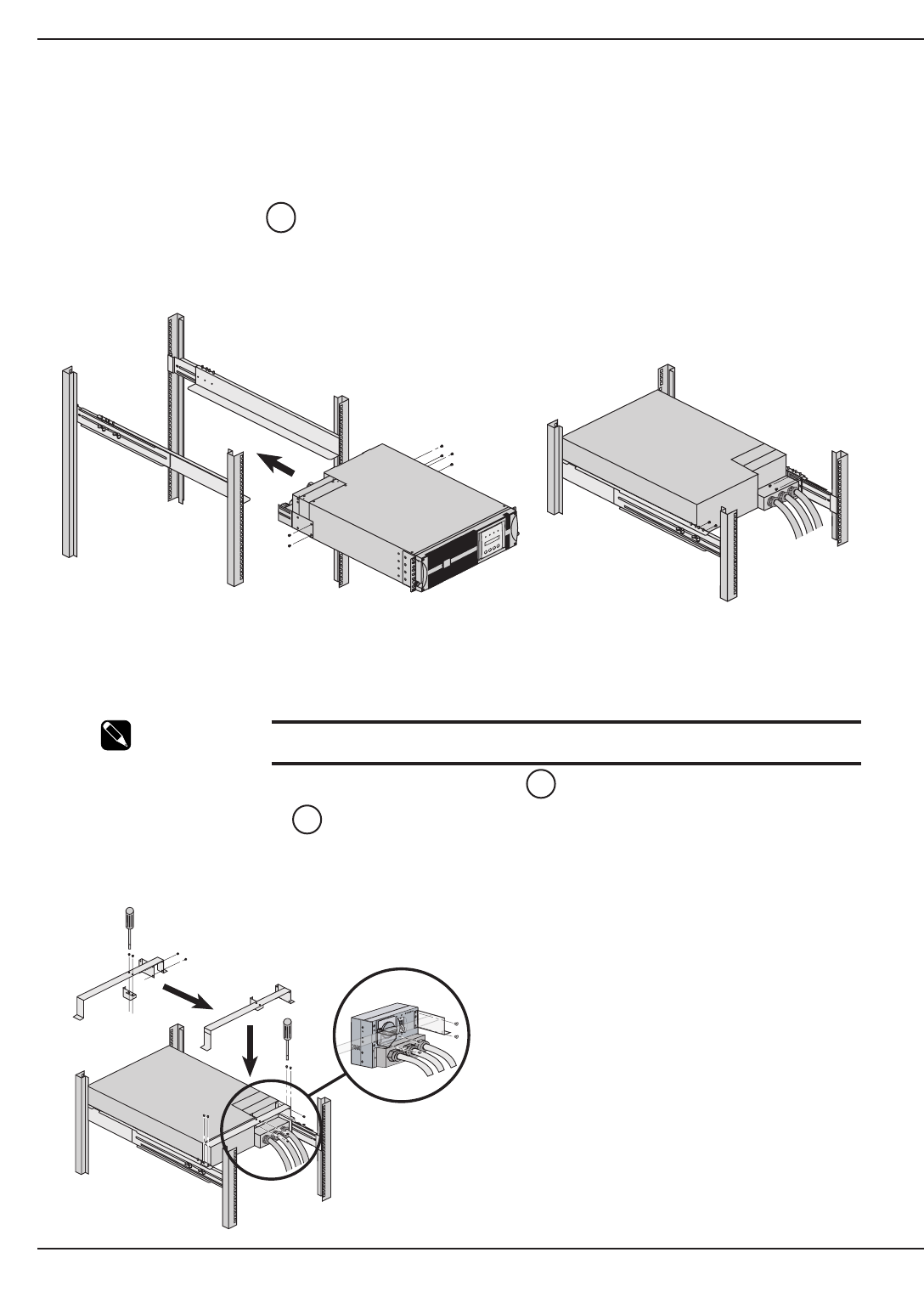
2.6.1 Rear Support Brackets Installation
(Part number 86013, included with rack mounting kits, part numbers: 86001 and 86002)
These brackets prevent the power module from moving when the entire rack enclosure is moved.
Proceed as follows:
1. Attach the brackets to the I/O Box and power module.
2. Secure brackets to rails.
Figure 2-7a: Rear Support Brackets.
2.6.2 Input/Output Box Bracket System Installation
(Part number 86012 included with power module rack mounting kit, part numbers: 86001)
This bracket system keeps the I/O Box stationary while hot swapping the power module. It will then be easier to slide
the replacement module into the connectors of the I/O Box.
NOTE: The rear support brackets must be removed prior to
installing I/O Box bracket system.
1. Secure small bracket to larger bracket from the underside .
2 & 3. Secure large bracket (with supplied screws) to rails at the rear of module.
4. Secure small attached bracket (with supplied screws) to the I/O Box.
Figure 2-7b: Input/Output Box Bracket System.
27
27
25
EX 5/7/11 RT System
Installation2 — 8 86-86000-00 A01
1
1
2
2
OFF
1
2
3
3
4
4
Installation and User Manual
2.7 Communication Ports
EX 5/7/11RT provides 3 communication methods that can be used simultaneously:
◗The COM port provides RS232 communications using MGE Serial HID UPS Transfer (SHUT)protocol.
This COM Port is compatible with Personal Solution Pac (PSP) to shutdown one computer. Personal Solution
Pac is included in the Solution Pac CD-Rom. For Network Management or multiple computer shutdowns an
optional network card must be purchased.
◗The Dry Contact Port is used for basic signaling or for protection of IT systems like IBM iSeries (formerly
AS400) and more.
◗The slot is compatible with any MGE UPS SYSTEMS, INC. communication card (check www.mgeups.com
web site for the complete list of compatible cards)
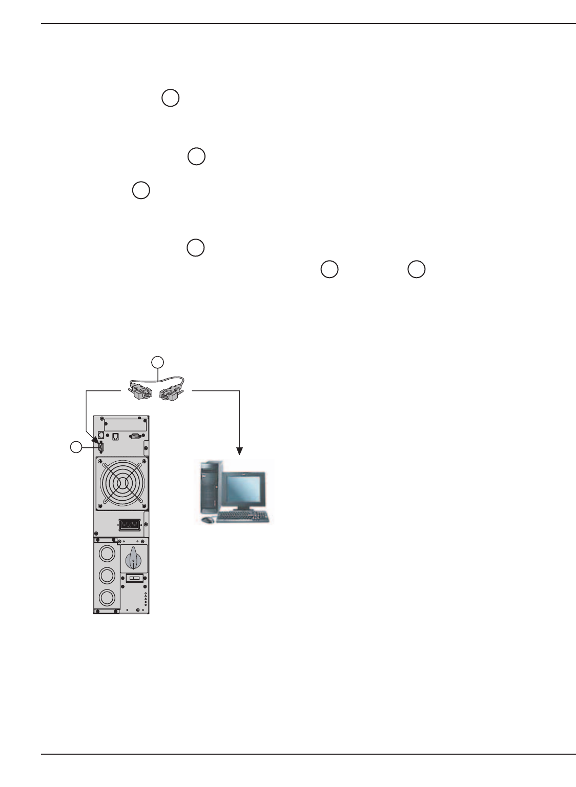
2.7.1 Connecting the RS232 Communication Port
1. Connect the RS 232 communications cable to the serial port on the computer.
2. Connect the other end of the communications cable to the RS 232 communications port on the
EX 5/7/11 RT.
The EX 5/7/11 RT System can now communicate with Personal Solution Pac for power management. UPS config-
uration settings are done by Personal Solution Pac for Windows.
Figure 2-8: RS232 Communication Cable Connection.
532
32
1
2
5
Installation 2 — 986-86000-00 A01
32
5
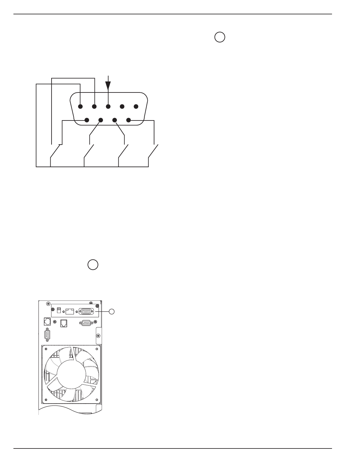
2.7.2 Connecting the Dry (Relay) Contact Communication Port
The system status is indicated by the connection of common pin (Pin 5) to the appropriate pins. Refer to the pin
explanations below for details.
Figure 2-9: Relay Pin Connections for Communication Port.
2.7.3 Installation of Optional Network Management Card
It is not necessary to shut down the UPS to install the optional communications card, except for USB card. Following
is a typical installation of the Network Management Card, (PN 66074, standard with the network pack option.)
Proceed as follows:
1. Remove the slot cover secured by two screws.
2. Insert the card into the slot.
3. Secure the card with both screws.
Figure 2-10: Communication Card Slot with SNMP/Web Network Management Card installed.
37
2
EX 5/7/11 RT System
Installation2 — 10 86-86000-00 A01
123
45
6789
NONC NONO
common
NO
Pin 1, 2: not used.
Pin 3: Remote Power Off signal (5 to 27 VDC, 10 mA max).
Pin 4: Operation on mains (not on battery). (48VDC, 2A max.)
Pin 5: User common.
Pin 6: Operation on automatic bypass.
Pin 7: Low battery.
Pin 8: Load protected
Pin 9: Operation on battery.
Legend:
NO: contact normally open.
NC: contact normally closed.
37

Installation and User Manual
A wide range of optional cards will allow your UPS to talk to nearly all equipment management systems, making
integration faster and easier. All these cards can plug directly into the UPS, saving time and money on your next
UPS project. (Meta UPS Card and U-Talk /Basic Acquisition Cards are used exclusively with Multi-slot.)
Dual U-Talk/Basic Card (66060)
Provides two communications ports that may be configured
for serial link or AS/400 type dry contacts.
ModBus Card (66061)
Interface your UPS with a Building Management System.
Dual COM Ports Card (66066)
This card has two independent RS232 communication ports
on which it can be connected. One for connecting monitoring software
(included) and one for remote control panel UPS control.
USB Card (66067)
Take advantage of the latest and fastest communication
protocol for Microsoft Windows 2000/XP or Mac OSX.
Dual Volt Free Contacts (66068)
The two ports are used to supply UPS status information
Card for AS/400 or one port can be used as a Remote Power Off (REPO) port.
Alarm Relay Card (66069)
Six output relays show UPS status and two status inputs are
used with the Galaxy 3000 UPS.
XML-Web Card (66073)
XML-Web Card acts as a web page for your UPS information.
Used along with XML-ClientTM software, up to 50 servers or workstations will
be protected and can monitor the UPS with a simple web browser.
Security is handled with the SSL protocol, used by many websites to
safeguard sensitive password information.
SNMP-Web Card (66074)
The SNMP/Web 10/100BT communications card is
both an SNMP agent and an HTTP/Web server. Therefore, it
enables UPS supervision from any Network Monitoring
System using SNMP traps or simply from any web
browser (Internet Explorer, Netscape Navigator, etc.)
Orderly system shutdown of up to 32 protected servers can
be established using MGE’s Solution-Pac/WAN software
suite.
Installation 2 — 1186-86000-00 A01
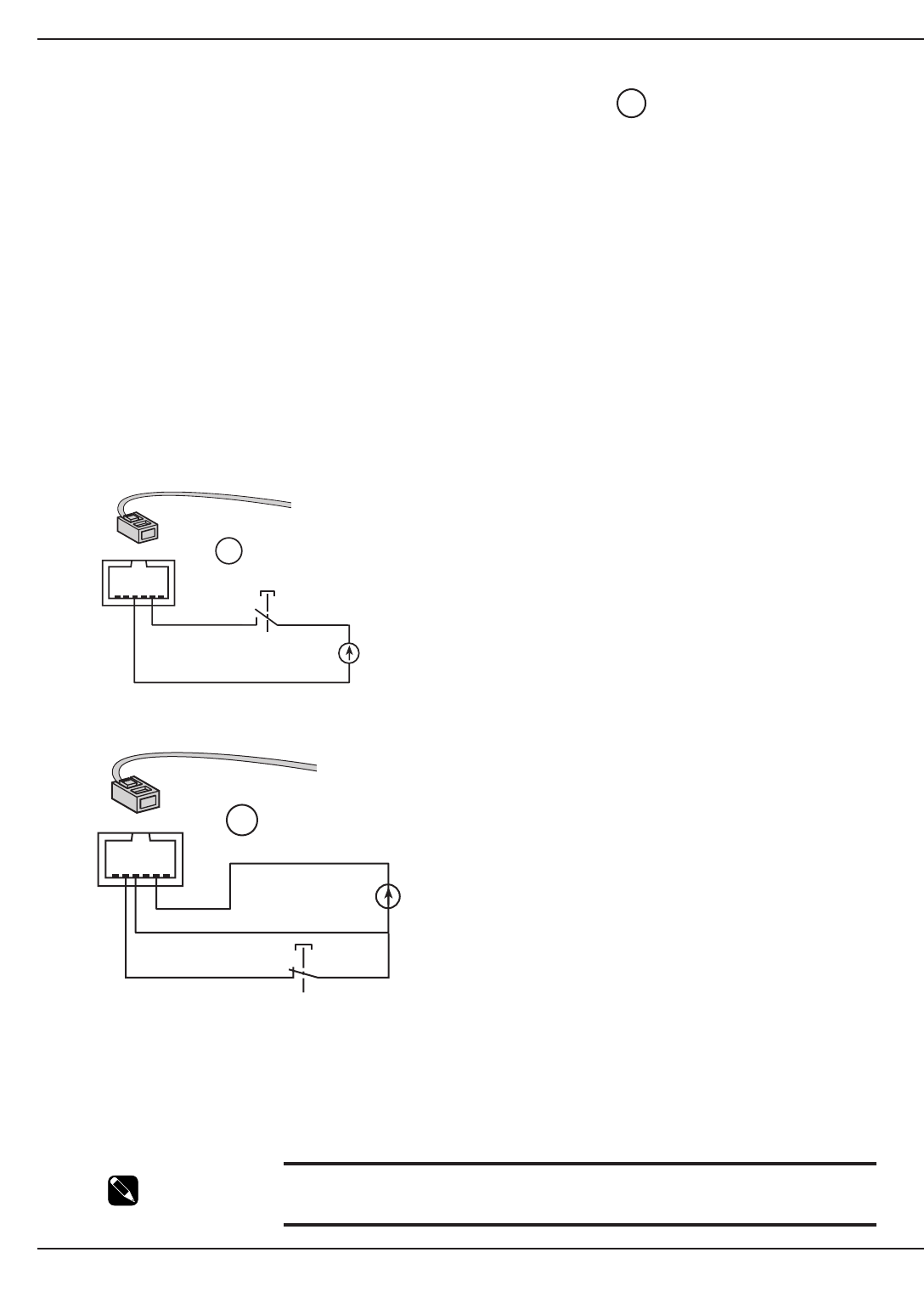
2.7.4 Remote Emergency Power Off (REPO) Communication Port
The end user is responsible for the installation of an emergency power off function. Installation must be carried out
in compliance with local code regulations.
To shutdown the entire system completely in case of emergency:
Disconnect the AC input to the power module.
Turn off the circuit breaker of the battery module connecting to the power module.
Turn off the circuit breaker of the subsequent battery modules, if applicable.
All these steps above should be performed via a single device.
To simplify the last two steps above, the power module provides an RJ-45 connector on the back panel, called
Remote Emergency Power Off (REPO) port. Upon applying a voltage source (5-27VDC, 10mA max.) to pins 2, 4 of
this port, the power module will send a signal to trip off the shunt trip on each circuit breaker of all battery modules
via the battery detection cable simultaneously. Refer to the diagram below for details.
Figure 2-10a: Activation of remote power off function using a contact normally open switch.
Figure 2-10b: Activation of remote power off function using a contact normally closed switch.
Signal:
Activation voltage: 5VDC to 27VDC
Current 10 mA (max)
NOTE Both AC and DC sources must be present for normal start-up of EX 5/7/11RT
system. If the system is configured for cold start, the AC and DC sources are
required for initial start-up only.
3
EX 5/7/11 RT System
Installation2 — 12 86-86000-00 A01
RJ11
54321
6
3
54321
6
RJ11
3
Installation and User Manual
2.8 Connecting the Input and Output Power Cables to the Input/Output Box
WARNING This type of connection must be carried out by qualified electrical personnel.
Before carrying out any connections, check that battery circuit breaker is OFF
and that the upstream protection devices (Normal and Bypass AC
sources) are open (OFF).
EX 5/7/11 RT UPS always comes from factory with Normal and Bypass AC inputs
already connected together, using a shunt.
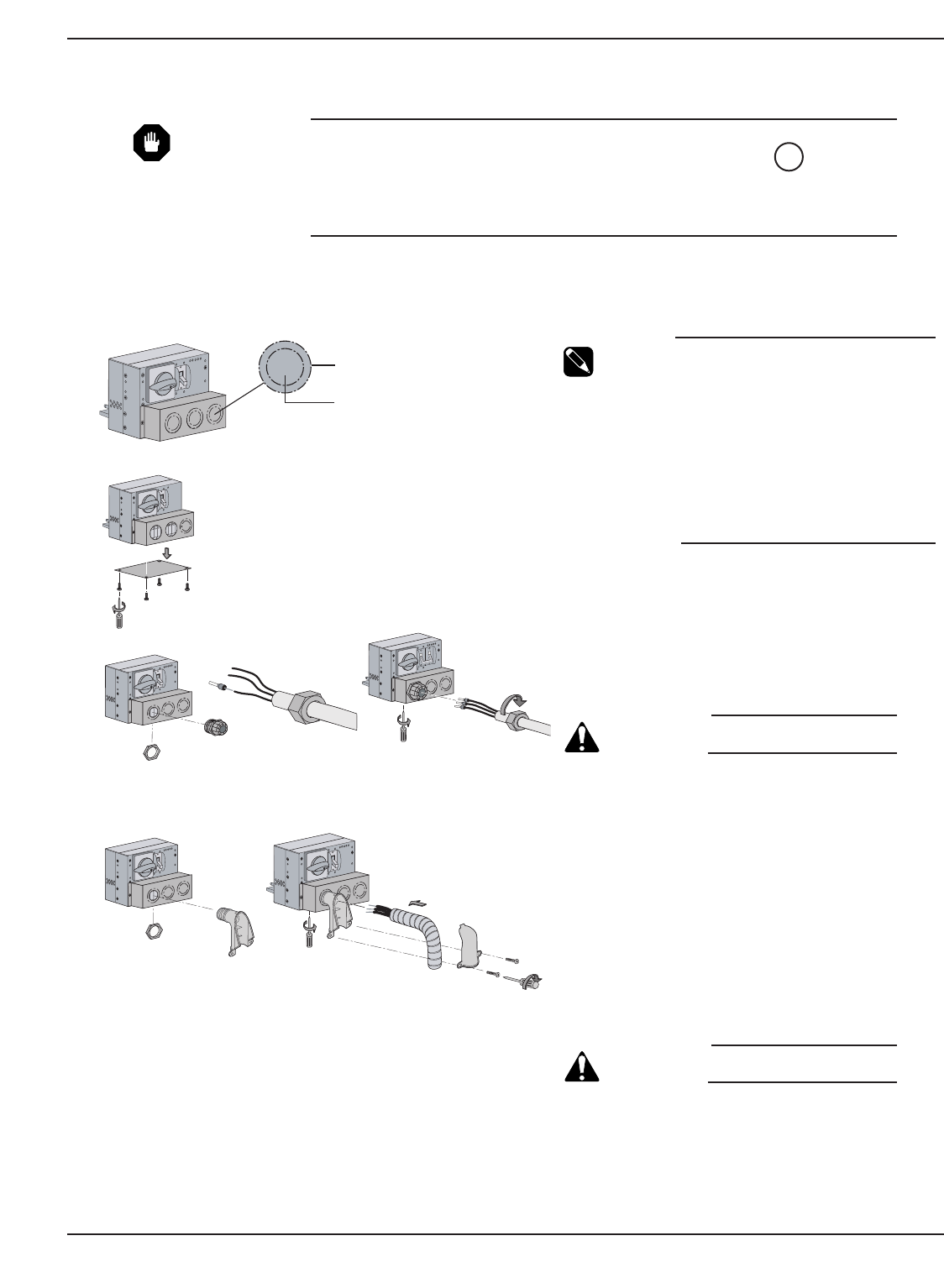
2.8.1 Flexible Cordage and Conduit Installations
Figure 2-12a: Step 1 & 2; Typical plastic and metal coupling installations.
14
Installation 2 — 1386-86000-00 A01
OFF
0
OFF
0
3. Typical Flexible Cordage Installation
Inner circle is for
Metal strain relief
Outer circle is for
Plastic strain relief
(a)
(b)
4. Typical 90° Metal Conduit Installation
(a)
Terminal Block Cover
(c)
(d)
I/O BOX
NOTE: Place lug ring inside
the terminal block cover.
Screw coupling into lug ring.
NOTE: Place lug ring inside
the terminal block cover.
Screw coupling into lug ring.
(b)
(c)
(d)
OFF
O
OFF
O
OFF
O
OFF
O
2
OFF
O
1
1. Knockout die stamp circles.
NOTE Terminal cable capacity:
Max. 4 AWG (11kVA), 6 AWG
(5/7kVA).
Knockout die stamp
circles (on terminal block
cover) have two sizes that fit
either plastic or metal
coupling. Plastic coupling is for
flexible cordage
and metal coupling is for solid
wires. Knock out appropriate
circle for your application.
2. Remove bottom cover plate as shown.
3. Typical plastic strain relief installation:
a) Secure strain relief body onto the
knockout plate.
b) Strip the jacket back to expose the
three wires. Strip the insulation of
each wire back 1/2”. Insert the
ferrules as shown to each wire.
CAUTION: Always connect the
earth ground wire first.
c) Slide the cordage into the strain relief
and secure the wires into the
terminal blocks using the guide
printed on bottom of I/O box.
d) Secure the cordage retainer nut.
4. Typical 90° metal conduit installation.
a) Secure strain relief body to knockout
plate as shown.
b) Insert three wires through flexible
conduit and bend 90°.
c) Strip the insulation back 1/2” to
expose solid wire and secure three
wires into the terminal block using
guide printed on bottom of I/O box.
CAUTION: Always connect the
earth ground wire first.
d) Install strain relief cover using two
screws.
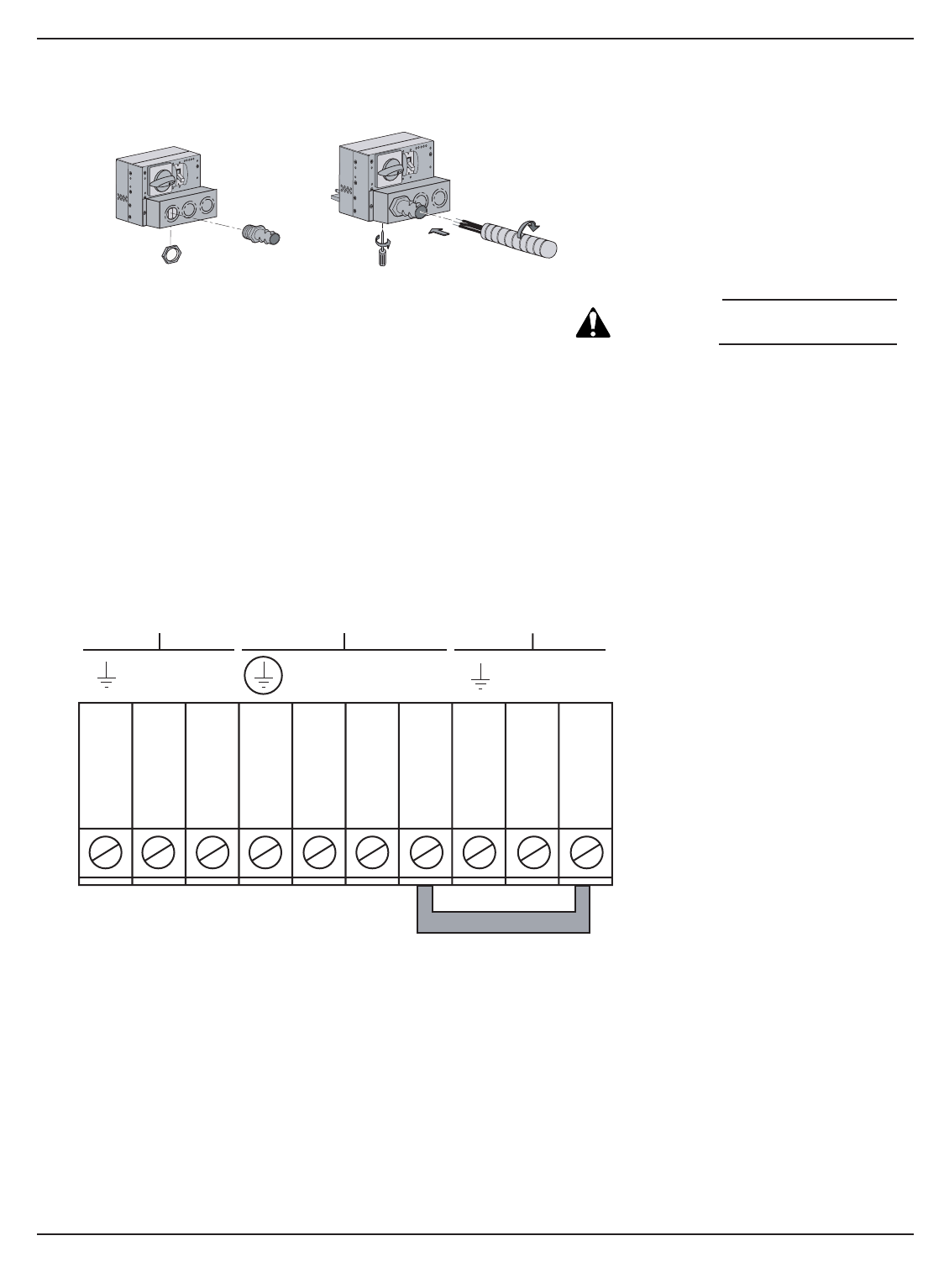
Figure 2-12b: Step 3; Typical Straight Metal Conduit installation.
Figure 2-12c: I/O Box Terminal Block Diagram.
EX 5/7/11 RT System
Installation2 — 14 86-86000-00 A01
5. Typical Straight Conduit Installation
(a)
NOTE: Place lug ring inside
the terminal block cover.
Screw coupling into lug ring.
(b)
(c)
(d)
OFF
O
OFF
O
(e)
5. Typical straight metal conduit
Installation.
a) Secure strain relief onto the
terminal block cover as shown.
b) Insert three wire through flexible
conduit.
c) Strip the insulation of each wire
back 1/2” to expose solid wire.
CAUTION: Always connect the
earth ground wire first.
d) Secure three wires into the terminal
block using guide printed on bottom
of I/O box.
e) Twist the conduit onto the coupling
body as shown.
L6 L5 L2 L1 L1 L4 L3
Jumper
Output
200/208/220/230/240Vac
Normal AC Source
200/208/220/230/240Vac
Bypass AC Source
200/208/220/230/240Vac
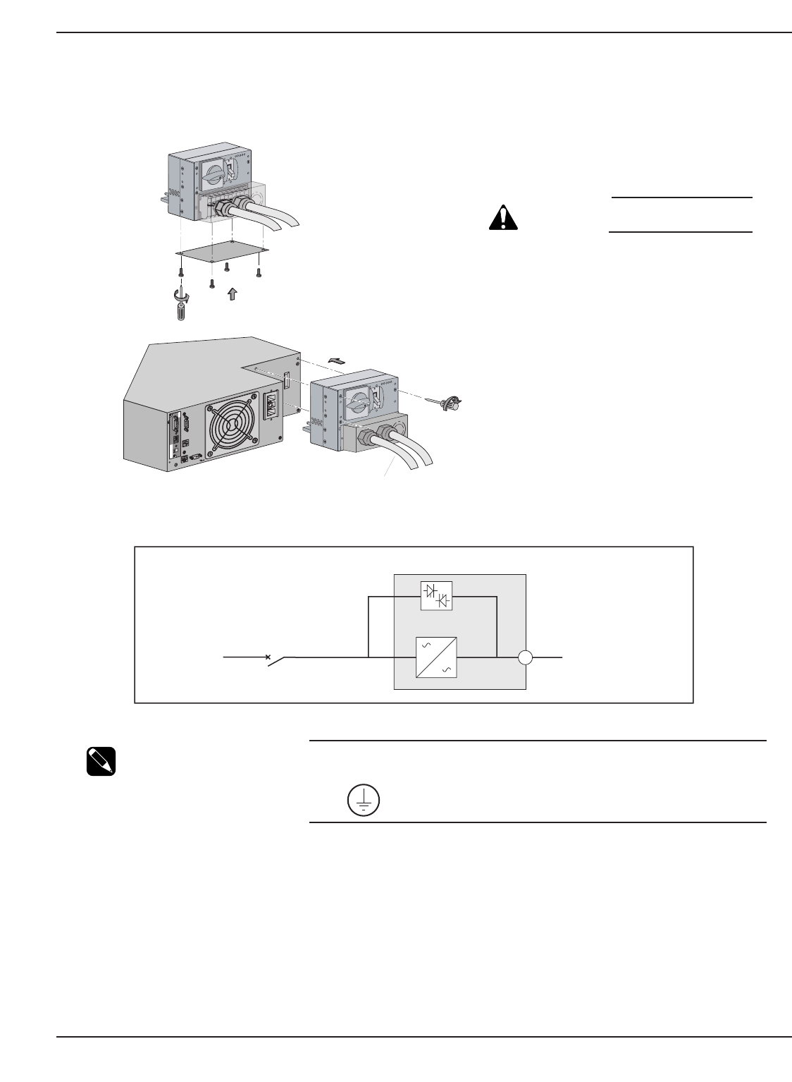
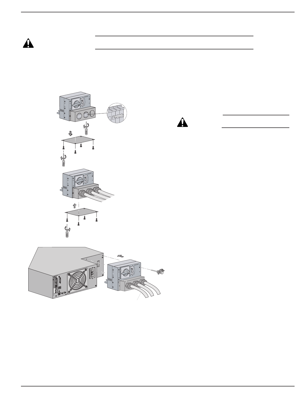
2.8.2 System Connections with Common Normal and Bypass AC Sources
Figure 2-13: Normal AC Input and Output Cables installation.
NOTE: The power module factory default is for the common normal and bypass
AC source (single Main). AC input connections must be made to L1, L2,
and terminals.
Installation and User Manual
Installation 2 — 1586-86000-00 A01
Card Settings
RS232 Download
66074
UPS
data
Reset
100 10
1 2
ON
ETHERNET
IP=
MAC=00E0D8FF855E
1
2
OFF
O
OFF
O
To Step-Down
Transformer
(if applicable)
8
AC INPUT
UPSTREAM
CIRCUIT
BREAKER
(NOT SUPPLIED) Load to
Transformer Module
Bypass AC
Normal AC
Simplified Connection Diagram
Proceed as follows:
1. Remove the I/O box from EX 5/7/11RT by
loosening three screws. Knockout appro-
priate circle for your wire style.
CAUTION: Always connect the
earth ground wire first.
1. See section 2.8.1 to install normal AC
source and output wires per I/O Box
Terminal diagram. Re-install the cover plate
under the I/O Box.
2. Install the I/O Box with three screws.
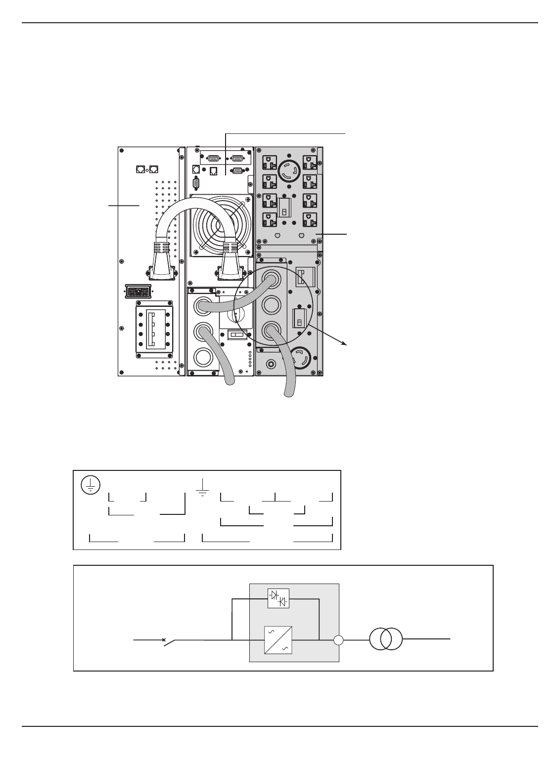
2.8.3 Connecting EX RT Transformer
(Part number 86003)
This module is to provide isolated 120/208/240 VAC outputs to the protected loads.
Figure 2-14: View of EX RT transformer connected downstream for 120/208/240 Vac outputs (shown with one EXB).
EX 5/7/11 RT System
Installation2 — 16 86-86000-00 A01
POWER MODULE
EX 5/7/11 RT
TRANSFORMER
MODULE EX RT
AC NORMAL
INPUT STEP-DOWN
TRANSFORMER
OUTPUT TO LOAD
Terminal Block Transformer Module Connection diagram
(located on bottom of Transformer I/O Box)
L3 L2 L1 Lb Ld N Lc La
208Vac
240Vac
AC Input
120Vac
208Vac
AC Output
120Vac
240Vac
Follow connection diagram for
appropriate input/output voltages.
Terminal Block capability :
AWG 4 solid or stranded wire.
BATTERY MODULE
EXB 5/7/11 RT
8
AC INPUT
UPSTREAM
CIRCUIT
BREAKER
(NOT SUPPLIED)
Transformer Module
Bypass AC
Normal AC
Simplified Connection Diagram
To L o ad
Installation and User Manual
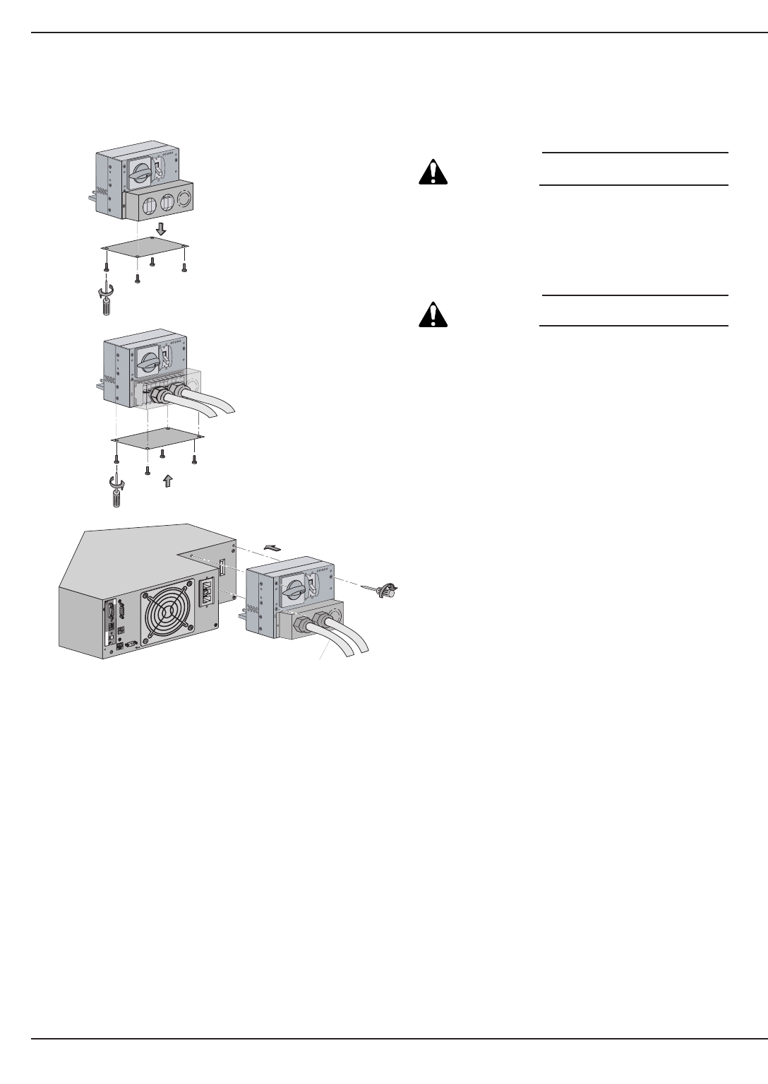
2.8.4 System Connections with Separate Normal and Bypass AC Sources
CAUTION: This installation requires 2 AC input source with Line, Neutral plus Ground,
(200-240VAC). Neutral points are connected together inside the UPS.
Figure 2-15: Normal AC Input, Bypass AC, and Output Cables Installation.
Installation 2 — 1786-86000-00 A01
Proceed as follows:
1. Remove the cover plate under the I/O Box. Loosen
the terminal blocks L1 and L3, and remove the
jumper.
CAUTION: Always connect the
earth ground wire first.
2. See section 2.8.1 and I/O Box terminal diagram for
installation of Normal AC Input, Bypass AC
source, and Output cable with different wire style.
3. Reinstall the cover plate under the I/O Box with
four screws.
4. Secure the I/O Box to the power module using
three screws.
See section 2.8.3 for connecting EX RT
Transformer, if applicable.
4
Card Settings
RS232 Download
66074
UPS
data
Reset
100 10
1 2
ON
ETHERNET
IP=
MAC=00E0D8FF855E
1
3Output
Bypass
Normal
L1
L3
OFF
O
OFF
O
OFF
O
To Step-Down
Transformer
(if applicable)
2
2.8.5 System Connections as Frequency Converter (without Bypass AC Source)
Figure 2-16: Accessing Terminal Blocks for Input and Output power cables.
EX 5/7/11 RT System
Installation2 — 18 86-86000-00 A01
CAUTION: Always connect the
earth ground wire first.
1. Remove the cover plate under the I/O Box.
Remove the jumper connecting L3 and L1.
CAUTION: Do not connect anything to the
Bypass AC terminal block.
2. Refer to section 2.8.1 to install normal AC source
and output wires per I/O Box Terminal diagram. Re-
install the cover plate under the I/O Box.
3. Secure the I/O Box to power module with three
screws.
See section 2.8.3 for connecting EX RT
Transformer, if necessary.
Card Settings
RS232 Download
66074
UPS
data
Reset
100 10
1 2
ON
ETHERNET
IP=
MAC=00E0D8FF855E
2
1
3
OFF
O
OFF
O
OFF
O
To Step-Down
Transformer
Installation and User Manual
2.9 Connection of Battery Module, EXB
1. Check that the battery circuit breaker is OFF (“0”) position.
2. Connect the battery power cable to the connectors and of the power and battery
modules.
3. Connect the battery detection cable between connectors and of the power and battery
modules.
Figure 2-17: Rear view of battery module cable connections.
124
42
13640
14
Installation 2 — 1986-86000-00 A01
4
42
40
13
14
6
12
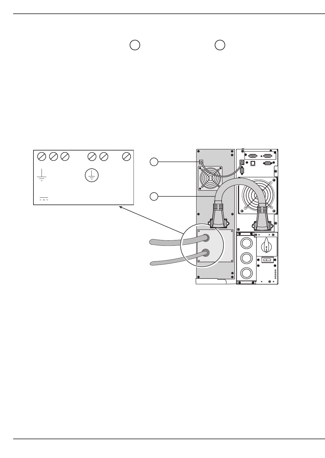
2.10 Connection of CLA Module
1. Connect the battery power cable and battery detection cable (provided with the CLA module)
between the power module and the CLA module.
2. Connect the DC Input of the CLA to high power battery cabinet.
◗ DC Input Cable cross-section (not provided): maximum 4 AWG solid or stranded wire.
3. Connect the AC input cable of the CLA module to the utility AC input:
◗ AC input cable cross-section (not provided): maximum 16 AWG solid or stranded wires.
Figure 2-18: Rear view of CLA module cable battery and AC input connections.
4240
EX 5/7/11 RT System
Installation2 — 20 86-86000-00 A01
To High
Power Battery
Cabinet
Utility AC Source
42
40
Connection Diagram
(inside CLA Module)
- +
DC INPUT
240Vdc
N L
(L2) (L1)
AC INPUT
156-280Vac
Operation
3.0 Scope
Operation describes EX 5/7/11RT system characteristics of indicators and controls, modes and specifications and
theory of operating the EX 5/7/11RT. The user procedures include performing software programming that will
maintain smooth performance. Refer to Figure 1.6 for descriptions of circled numbers.
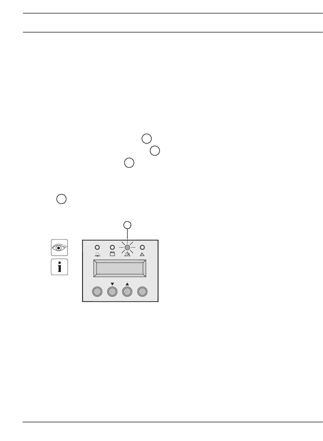
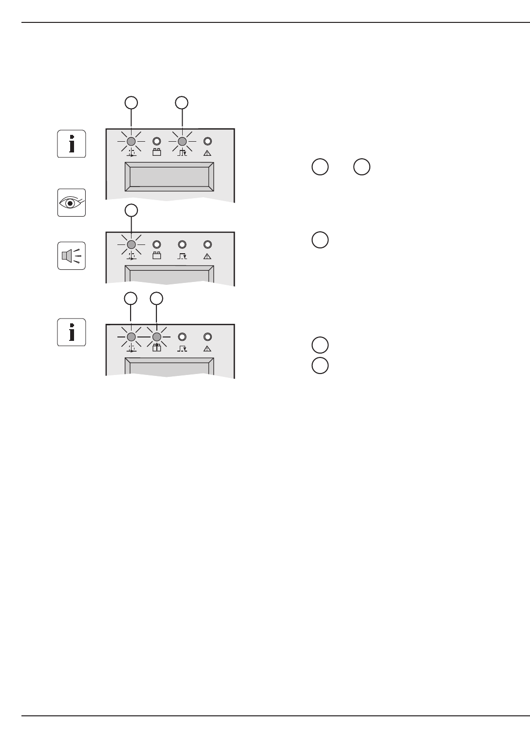
3.1 Initial Startup
1. Check that the manual bypass switch is on Normal position.
2. Set the normal AC source circuit breaker to the ON position.
3. Set the battery circuit breaker to the ON position.
The load is powered via the bypass AC source, but not protected by the UPS.
Batteries are recharging, an eight-hour recharge period is necessary to get full backup time.
LED is ON.
Figure 3-1: Initial Startup Display.
17
14
8
7
3 — 186-86000-00 A01 Operation
OFF ON
17
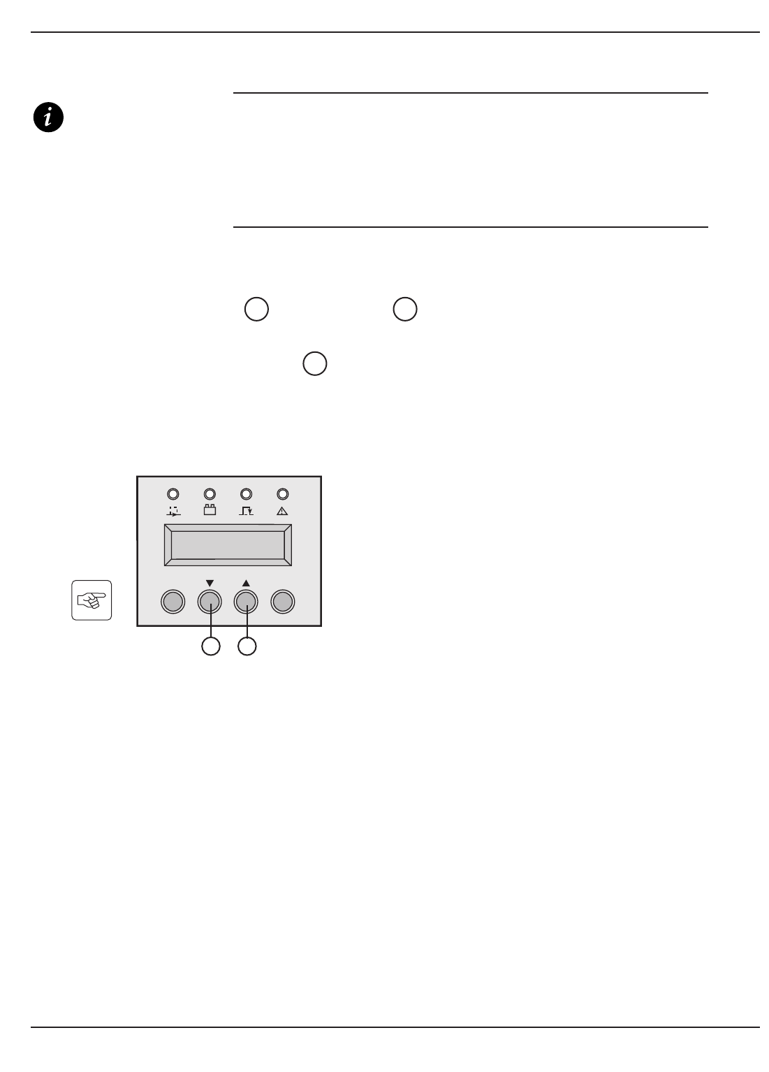
3.2 UPS Personalization
IMPORTANT If specific settings are required, it is recommended to
enter the UPS personalization mode at this stage.
It is possible to enter this mode through the front panel
buttons or the Personal Solution-Pac software for
Windows included in the MGE UPS SYSTEMS, INC. Solution-
Pac power management suite CD-ROM.
3.2.1 Accessing personalization with front panel buttons
◗Press "scroll up" and "scroll down" function buttons together for more than 3 sec-
onds.
◗Press the function button placed under the “ENT” word to enter the set up mode and
follow the LCD messages using the buttons now defined as select keys. See Tables: 3-1,
3-2, 3-3, and 3-4 for settings.
Figure 3-2: Control Panel with scroll up and down buttons.
21
2120
EX 5/7/11 RT System
Operation3 — 2 86-86000-00 A01
OFF ON
20 21
UPS SET UP
EXIT ENT
Installation and User Manual
Table 3-1: Local Settings.
Display Factory setting Options
Language English French, Spanish, German, Italian
Date / time format International format US format
(DD-MM-YYYY/HH:MM) (MM-DD-YYYY/HH:MM AM/PM)
Date / time change GMT (Greenwich Mean Time) MM-DD-YYYY/HH:MM adjustable
Audible alarm Quick beeps Slow beeps
Table 3-2: Output features.
Display Factory setting Options Comments
Output voltage 208 Volts AC 200/208/220/230/240/250
Frequency converter Disabled Enabled Bypass AC source disabled
Output frequency Auto ranging 50/60 Hz User selectable under
frequency converter mode
Eco mode Disabled Enabled See glossary
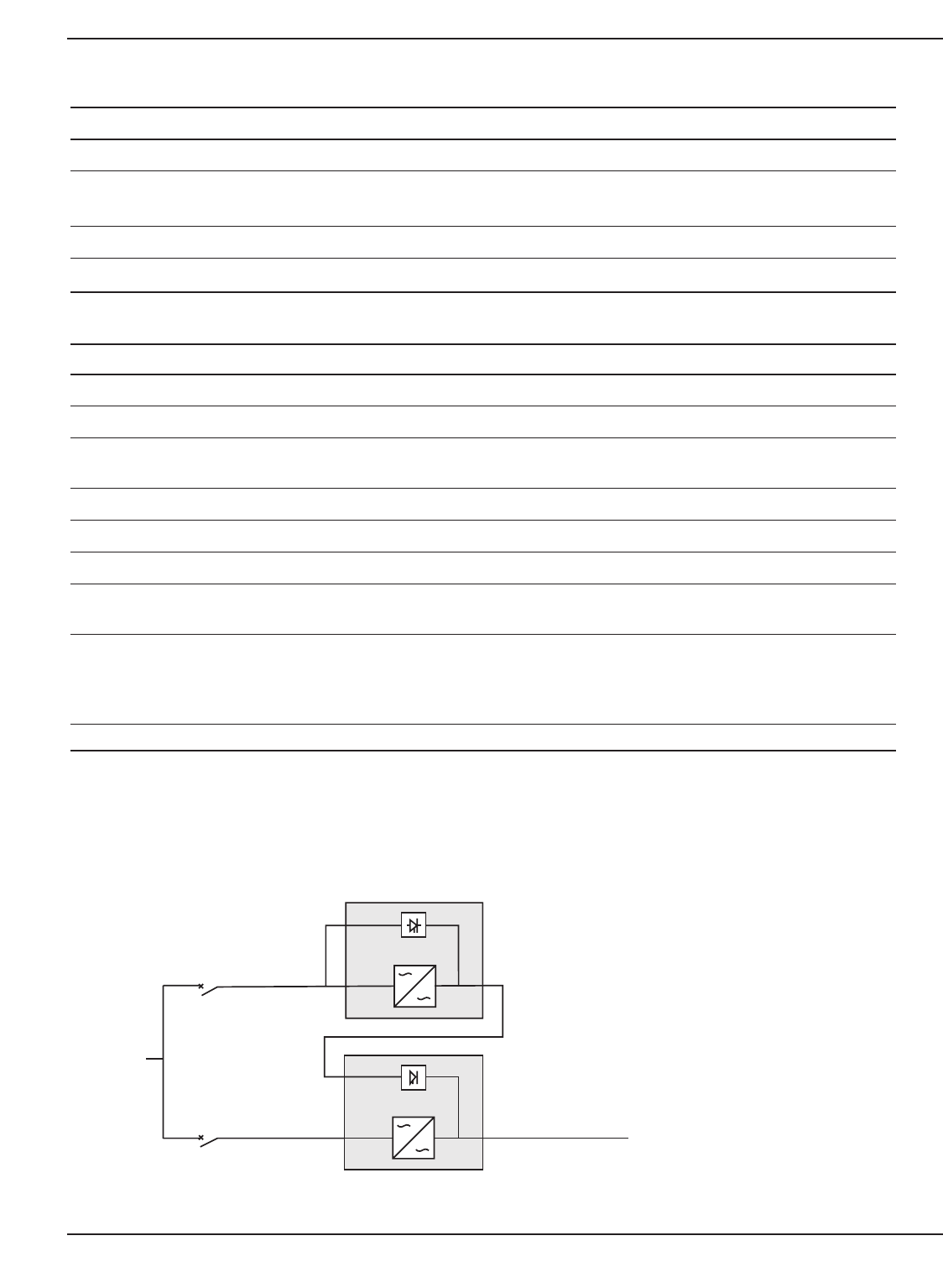
Hot standby Disabled Enabled Full redundancy (see Figure 3-3)
Operating mode IT Network Industrial (*) See Section 4.1
Bypass When bypass OK (**) When bypass NOK (**) (*)
Transfer
Interrupt time 10 ms 10 to 200 ms Interrupt time calibration during
(by steps of 10 ms) during load transfer on
Bypass AC source
out of tolerances
Overload level 102% 50/70%
(*) : - Select "IT Network" for computer loads.
- Select "Industrial" when bypass NOK in case of absolute need for service continuity (with potential
10 ms interrupt).
(**) UPS will switch to Bypass AC Source if it is within the set tolerances.
Figure 3-3: Configuration used to provide full redundancy (2N) to critical loads.
Operation 3 — 386-86000-00 A01
Utility
AC Source
NORMAL AC
LOAD
BYPASS AC
NORMAL AC
Protective Device
Protective Device
Full redundancy configuration
offers better protection to
critical load, whereas the first
UPS acts as the Bypass AC
Source for the second UPS.

Table 3-3: ON/OFF features.
Display Factory setting Options Comments
Cold start Disabled Enabled Start on battery.
Forced reboot Enabled Disabled Enables automatic restart of
the system even if normal AC
source is restored before the
end of the shutdown sequence.
Automatic restart Enabled Disabled UPS restarts automatically
when normal AC source
is restored.
Sleep mode Disabled Enabled Automatic shutdown on battery
if output load level <10%
Remote Command Enabled Disabled Enables shutdown or restart
orders from software.
Table 3-4: Battery features.
Display Factory setting Options Comments
Battery test Every week No test/daily/monthly
Pre-Alarm 20% 0 to 100% Low battery signal;1% increment
Runtime choice UPS reads # and type From 65 to 400 Ah Requires EX 5/7/11RT CLA if
of battery using options (see section 1.5.4
modules connected. “Battery extensions cable kit”)
Battery deep discharge Enabled Disabled If disabled, loss of
protection MGE UPS SYSTEMS,INC.
warranty.
3.2.2 Accessing personalization through external software
Insert the Solution-Pac CD ROM in your CD drive.
◗At the first Navigator Screen, select "Installation" and follow the instructions to install Personal
Solution-Pac for Windows.
◗If nothing appears, launch startup.exe
◗Then go to "Advanced settings" and "UPS settings".
Please note that the Linux/Unix/MacOS versions of Personal Solution-Pac do not include this feature.
3.2.3 Final startup sequence
Press the <ON> button more than 3 seconds.
◗After UPS internal test sequence, the green LED goes on.
CAUTION During the restart, if the Bypass AC source is out of
tolerance, the UPS will generate an output
calibrated 10 msec output interrupt.
15
EX 5/7/11 RT System
Operation3 — 4 86-86000-00 A01
Installation and User Manual
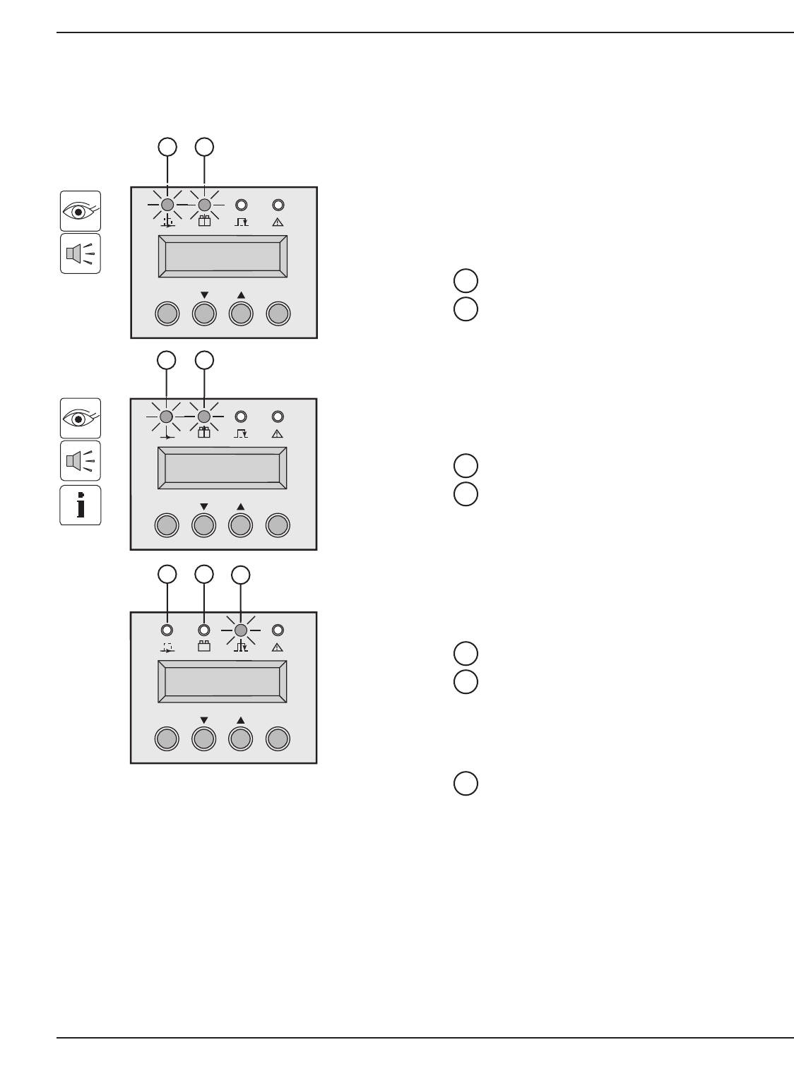
3.3 Operating Modes
3.3.1 Normal (double conversion) Mode
Figure 3-4: Normal (double conversion) mode.
Operation 3 — 586-86000-00 A01
OFF ON
OFF ON
15
15 16
LOAD LEVEL
4kW / 5 kVA
REMAINING TIME
10 minutes
This is the standard operating mode, set by the
factory.
Two possible cases.
1. If Normal AC source available:
LED is ON.
The load is protected by the UPS.
Scroll up and scroll down function buttons
allow you to read the UPS measurements (Normal AC
source voltage, Bypass AC source voltage, operating
mode, battery capacity and UPS Serial Number).
2. If Normal AC source not available:
CAUTION: Do not operate the Manual Bypass switch
when the UPS is in Normal mode.
LED flashes.
LED is ON.
The audible alarm sounds intermittently.
The load is now powered by the UPS battery.
This display shows remaining back-up time.
16
15
2221
15
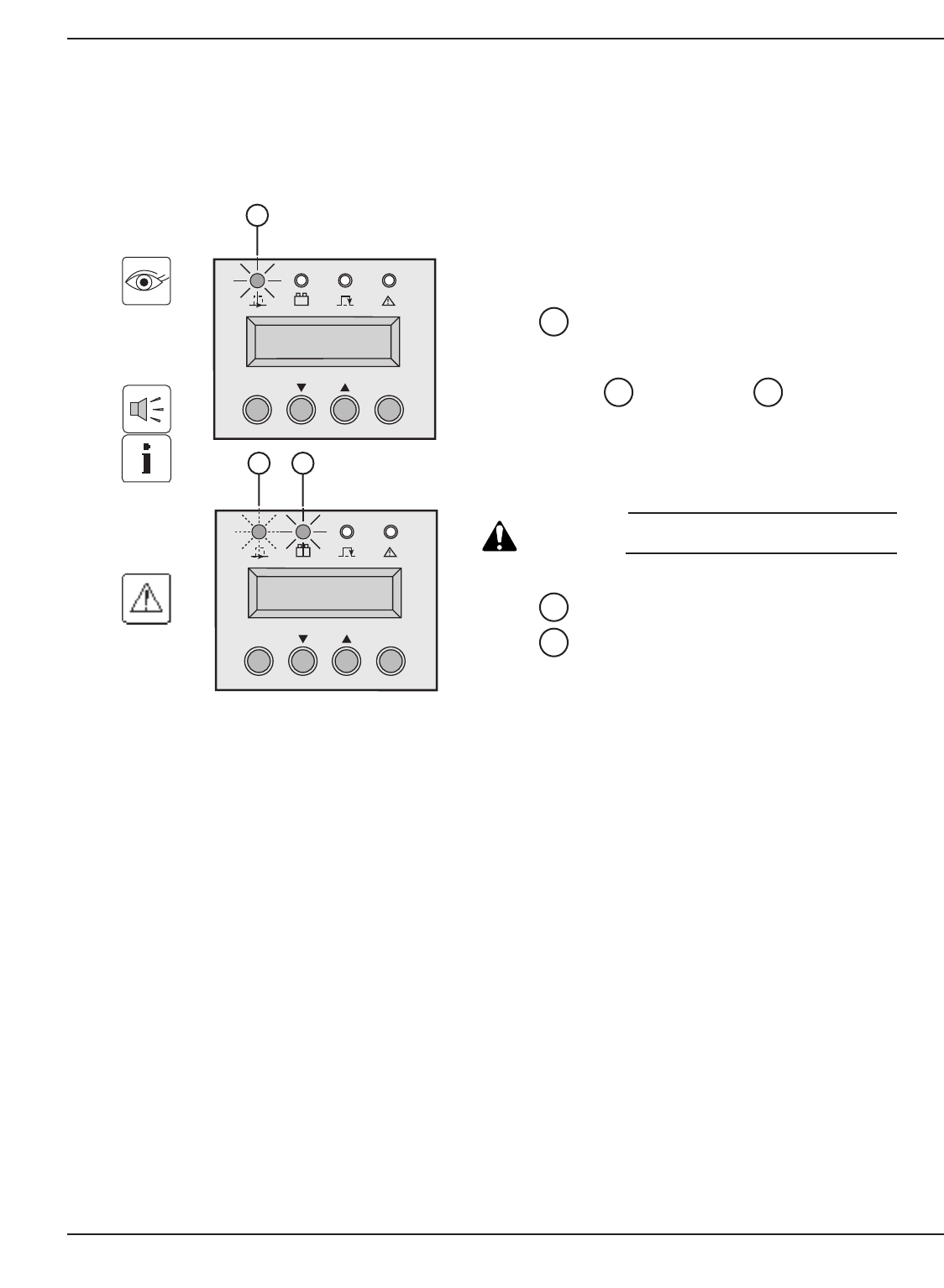
3.3.2 ECO Modes
Figure 3-5: ECO mode display.
EX 5/7/11 RT System
Operation3 — 6 86-86000-00 A01
The main advantage of the ECO mode (see glossary)
is that it reduces the consumption of electrical power.
Three possible cases:
1. If Bypass AC source available:
and LED are ON.
The load is supplied with AC power but not protected
in ECO mode.
2. If Bypass AC source not available:
LED is ON.
The audio alarm sounds intermittently.
The load is automatically supplied in Normal
mode via the Normal AC input.
3. Both Normal and Bypass AC sources not
available or out of tolerance:
LED is ON.
LED is ON.
The audio alarm sounds intermittently.
The load is powered by the battery power from the
UPS.
The display indicates the battery remaining
backup time.
16
15
15
1715
OFF ON
OFF ON
OFF ON
15 17
15
15 16
Installation and User Manual
3.4 Operation on battery power
Figure 3-6: Transfer, Threshold and End of backup time.
Operation 3 — 786-86000-00 A01
3.4.1 Transfer to Battery Power
The load continues to be protected by the UPS when
the Normal AC source is not available. Power is
supplied by the battery.
There are three possible cases:
First Case:
LED is ON.
LED is ON.
The audio alarm beeps every 10 seconds.
◗This indicate the load is supplied by the battery.
◗The display indicates the battery remaining
backup time.
Second Case:
LED is ON.
LED is ON.
The audio alarm beeps every 3 seconds.
◗Low battery warning on display. There is very little
remaining battery backup time. Close all appli-
cations because UPS automatic shutdown is
pending.
Third Case:
LED is OFF.
LED is OFF.
The audio alarm is stopped.
◗The load is transferred to the Bypass AC source if
available. In this case:
LED is ON.
17
16
15
16
15
16
15
OFF ON
OFF ON
15 16
SHUTDOWN DUE
TO DEPLETED BATTERY
REMAINING TIME
10 minutes
OFF ON
REMAINING TIME
2 minutes
17
15 16
15 16
3.5 Return of Normal AC source
After an outage, the UPS restarts automatically when AC power is restored (unless this function has been disabled
via UPS personalization).
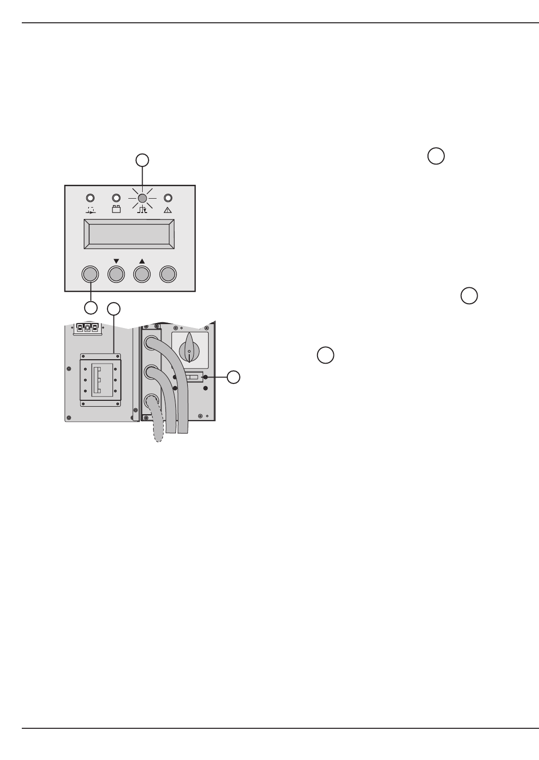
3.6 Shutdown
Figure 3-7: Shutdown display, circuit breaker, and AC source switch.
EX 5/7/11 RT System
Operation3 — 8 86-86000-00 A01
1. Press the OFF button more than 3
seconds.
The load is no longer protected by the UPS. It is
powered via the bypass AC source. If the UPS is
set in frequency converter mode, the load will not
be powered.
If the bypass AC source is out of tolerance, the
UPS will generate a calibrated 10msec output
interrupt.
2. Set the battery circuit breaker(s) to the
OFF position.
3. Set the Normal AC source circuit breaker
to the OFF position.
4. For a full shutdown of UPS and connected
load, the upstream circuit breaker (not
included) should be set to the OFF position.
8
14
19
OFF ON
17
19
8
14

Maintenance
4.0 Scope
Maintenance includes a troubleshooting guide of symptoms and possible solutions, Hot swapping the power module
and Battery Module, and testing scenarios.
4.1 Information Technology (IT) Network and Industrial Operating Modes
Table 4-1: Network and Industrial Modes of Operation.
Symptoms IT network mode Industrial mode
Overload, and Bypass Load is transferred to Bypass AC source. Same as I/T network mode, but AC
source in tolerance. UPS returns to normal mode if overload to the UPS does not return to
is removed. normal mode if overload
is removed.
Overload, and Bypass The UPS shuts down and load is not Load is transferred to Bypass
AC source not in tolerance. transferred to Bypass AC source. AC source with 10 milli-
seconds output break.
The UPS does not return to
normal mode if overload
is removed.
Output short circuit and Bypass The load remains powered by the UPS. Load is transferred to Bypass
AC source in tolerance. The UPS shuts down after 3 minutes AC source, the UPS returns to
if the short circuit remains normal mode if the short circuit
is removed.
Output short circuit and Bypass The load remains powered by the UPS. The load is transferred to
AC source not in tolerance. The UPS shuts down after 3 minutes Bypass AC source with
if the short circuit remains. 10 milliseconds output break.
The UPS does not return to
normal mode if the short circuit
is removed.
4 — 186-86000-00 A01 Maintenance

4.2 Troubleshooting
◗If any of LED's or is on, there is an operating anomaly or an alarm.
◗Use "scroll up" or "scroll down" function button to reset the audible alarm.
◗Troubleshooting not requiring MGE UPS SYSTEMS, INC. after-sales support:
Table 4-2: Troubleshooting not requiring
MGE
after-sales support.
Symptom Indication Correction
LED is on, and Bypass AC AC source is not connected Rewire correctly the normal AC
source is present to the correct terminals. source.
the alphanumeric display shows
BAD CONNECTION
REWIRE AC NORMAL
LED is on, Load supplied by bypass AC source. Push the ON button for more than 3
the alphanumeric display shows: seconds.
LOAD LEVEL
XX kW / XX KVA
LED is on, and Bypass AC UPS overload Check if any device is shorted or failed.
source is present
the alphanumeric display shows:
THERMAL OVERLOAD
1XX%
LED is on, Short circuit conditions on output Check if any device is shorted or
devices. failed.
the alphanumeric display shows:
CURRENT OVERLOAD
LED is on, 180° degree phase shift between Check if bypass source is correctly
bypass and normal AC source. wired
but the alphanumeric display shows: (in case of upstream transformer use).
BYPASS REVERSE
REWIRE BYPASS
Audible alarm is on, Input/Output box not Check if the Input/Output box
the alphanumeric display shows: installed correctly. is correctly installed. See section 2.8.
I/O BOX REMOVED
15
18
17
17
17
1817
EX 5/7/11 RT System
Maintenance4 — 2 86-86000-00 A01

Installation and User Manual
Table 4-3: Troubleshooting requiring
MGE
after-sales support.
Symptom Indication Correction
LED and are on, Internal fault Call the after sales support department.
Bypass AC Source is present and transfer of load
and audible alarm is on. on bypass AC source
the alphanumeric display shows:
xxx FAULT
LED is on, and audible alarm Battery fault during the battery test. Call the after sales support department.
is on, the alphanumeric display
shows
BATTERY FAULT
LED is on, Static switch failure Call the after sales support department.
the alphanumeric display shows:
SHUTDOWN
STATIC SW FAILED
Audible alarm is on, Batteries may have exceeded Follow the battery replacement procedure
the alphanumeric display shows: their rated life period. Battery in section 4.5.
END OF WARRANTY capacity is severely reduced.
NOTE: To reset the alarm permanently, press both function buttons and for more than 3 seconds.
2221
17
17
1817
Maintenance 4 — 386-86000-00 A01
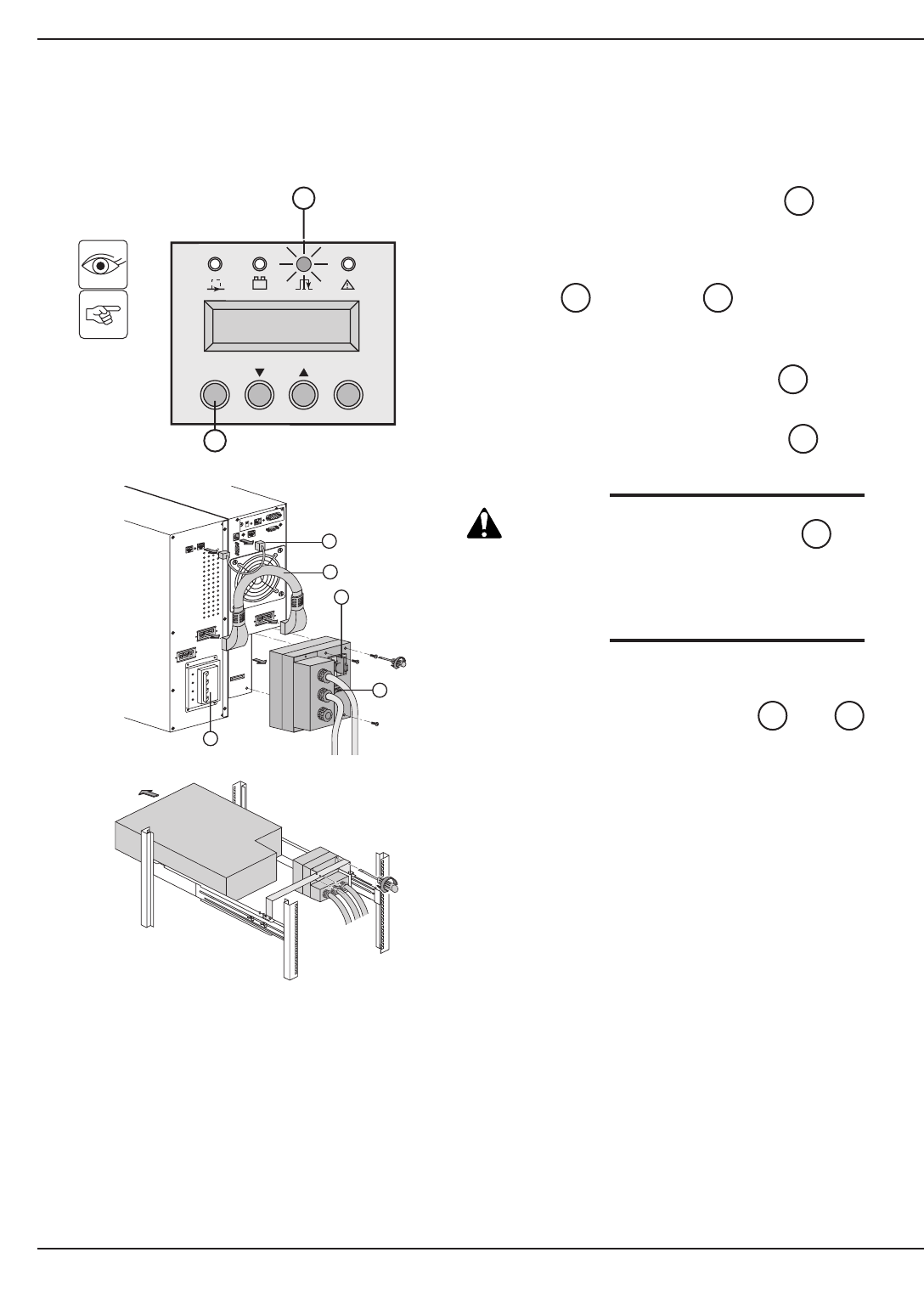
4.3 Hot Swapping the Power Module
This operation can be performed without interrupting the load.
Figure 4-1: Disconnecting the power module.
EX 5/7/11 RT System
Maintenance4 — 4 86-86000-00 A01
1. Stop the UPS with the OFF button (press
more than 3 seconds).
Check if UPS is on bypass AC source:
LED is on (If LED is not on, do not
turn the manual bypass and call the after sales
support department).
2. Turn the manual bypass switch to the
BYPASS position.
3. Switch the battery circuit breaker(s) to the
OFF position.
CAUTION: Do not switch the Normal AC
source circuit-breaker to
the OFF position. Doing so
will disconnect power to the
load.
4. Loosen three screws to remove the
Input/Output box.
5. Disconnect the battery cables and
from the power module.
The power module can be replaced.
The connected equipment is powered by the
Bypass AC source.
4240
8
14
7
1717
19
OFF ON
17
XXX FAULT
1CXXXXXXX
19
Card Settings
66074
UPS
data
Reset
100 10
1 2
ON
ETHERNETRS232
IP=
MAC=00E0D8FF855E
BY
PASS
φ
RS232 Download
7
8
12
T
ower configuration
Rack configuration
42
40
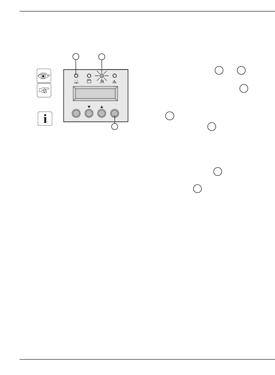
Installation and User Manual
4.4 Re-connecting the power module
This operation can be performed without interrupting the load.
Figure 4-2: Reconnect the power module.
Maintenance 4 — 586-86000-00 A01
1. Secure the Input/Output junction box using the
three screws.
2. Reconnect the cables and to the
power module.
3. Switch the battery circuit breaker(s) to the
ON position.
4. Check if Normal AC source circuit breaker
is on the ON position.
5. Check that the LED is on.
6. Turn the manual bypass switch from the
BYPASS to the NORMAL position.
7. Follow initial start up sequence (see section
3.1) in order to personalize the UPS.
8. Push the ON button for more than 3
seconds.
The green LED is on, and the connected
equipment is now protected by the UPS.
15
22
17
8
14
4240
OFF ON
17
LOAD LEVEL
4 kW/ 5 kVA
22
15
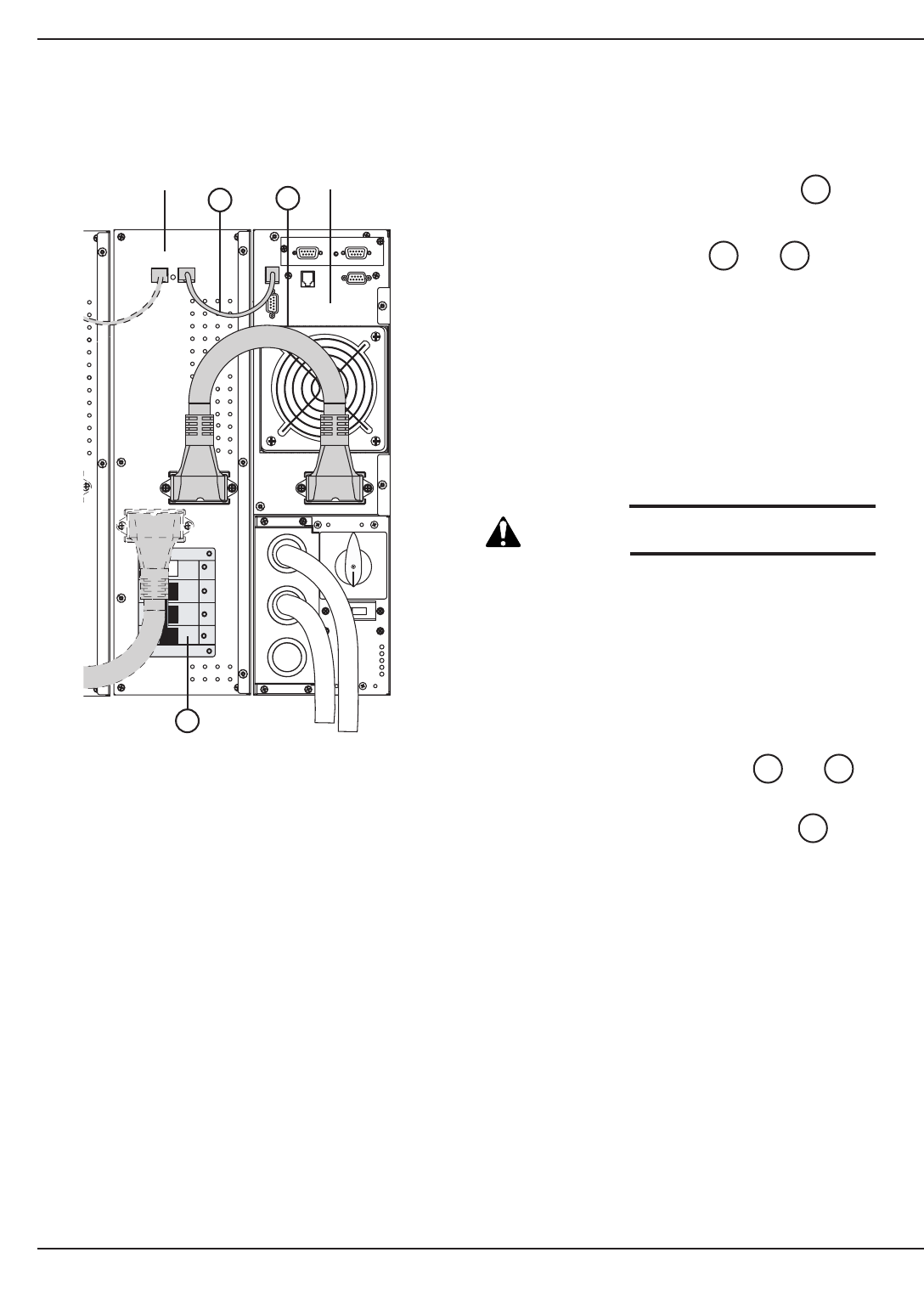
4.5 Hot Swapping the Battery Module
Figure 4-3: Rear view of the battery module.
EX 5/7/11 RT System
Maintenance4 — 6 86-86000-00 A01
4.5.1 Disconnecting the Battery Module
1. Switch the battery circuit breaker(s) to the
OFF position.
2. Disconnect the cables and from the
power module.
The battery module can be replaced.
The connected equipment is powered by the UPS,
but not protected.
It is also possible to replace battery pack instead of
battery module.
Contact your nearest after sales support service.
CAUTION: Always replace both battery
packs with new ones.
To remove battery pack:
1. First, switch the battery circuit breaker(s) to the
OFF position.
See section 2.5 and follow instructions for battery
pack replacement.
4.5.2 Re-connecting the Battery Module
1. Reconnect the battery cables and to
the power module.
2. Switch the battery circuit breaker(s) to the
ON position.
14
4240
4240
14
42 40
14
Battery Module Power Module
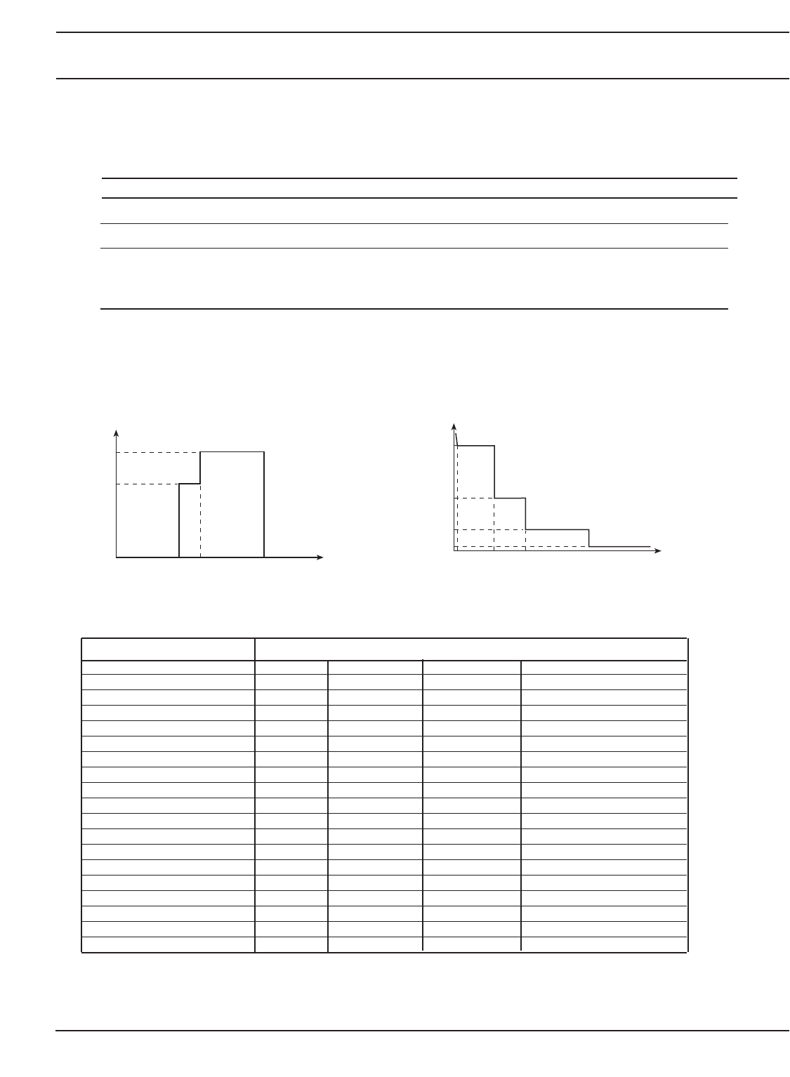
Appendix
5.0 Electrical Specifications
5.1 System Input/Output Power Ratings
Table 5-1: EX 5/7/11 RT Input and Output Characteristics.
Source Voltage Frequency
Normal AC Source 208 to 240 Volts AC 40 to 70 Hz
Bypass AC Source 208 to 240 Volts AC* 48 to 52 Hz**
Load Output 120/240Vac Volts AC 50/60 Hz autoranging
(120/208/240Vac (or frequency converter)
are possible with
transformer module)
(*): depends on output voltage setting, can be modified by software.
(**): set to +/- 4% by default, (1,2,4,8% are possible values), can be modified by software.
5.2 System Overload Characteristics
Figure 5-1: Power supplied as a function of input voltage (left), and Permissible UPS overloads as a function of time (right).
5.3 System Backup Characteristics
Table 5-2: Back-up Time ( in minutes).
System Load Percentage
30% 50% 70% 100%
Standard 11kVA 25 14 9 5
Standard 11kVA + 1 EXB 61 30 20 14
Standard 11kVA + 2 EXB 96 53 34 22
Standard 11kVA + 3 EXB 135 84 51 30
Standard 11kVA + 4 EXB 172 102 67 42
Standard 11kVA + 5 EXB 201 113 87 53
Standard 7kVA 37 21 12 7
Standard 7kVA + 1 EXB 80 53 30 20
Standard 7kVA + 2 EXB 124 83 55 32
Standard 7kVA + 3 EXB 185 108 75 45
Standard 7kVA + 4 EXB 245 132 98 57
Standard 7kVA + 5 EXB 287 164 118 72
Standard 5kVA 37 31 21 12
Standard 5kVA + 1 EXB 90 70 53 30
Standard 5kVA + 2 EXB 140 112 83 55
Standard 5kVA + 3 EXB 185 156 108 75
Standard 5kVA + 4 EXB 255 207 132 98
Standard 5kVA + 5 EXB 306 260 164 118
Appendix 5 — 186-86000-00 A01
100%
70%
120V U
160V 280V
Load Percentage
1.02
0.5s
t
30s
1.1
1.25
1.5
60s 120s
Load Percentage
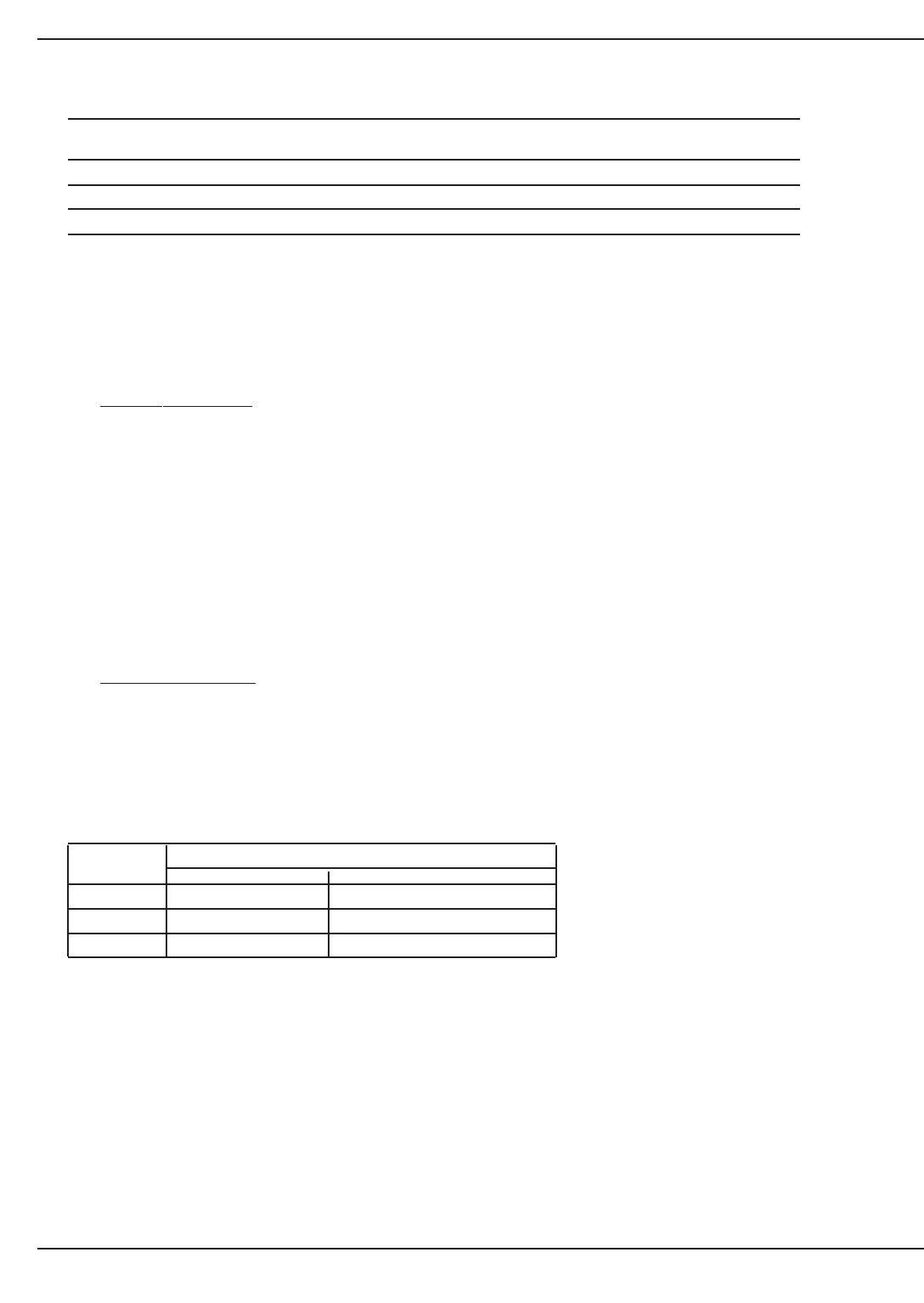
Table 5-3: Battery Recharge time to recover 90% of the rated backup time after discharge at full load.
Configuration for Configuration for Configuration for
2 hours backup time 4 hours backup time 8 hours backup time
EX 5 7 hours 15 hours 24 hours
EX 7 5 hours 12 hours 20 hours
EX 11 7 hours 15 hours 24 hours
5.4 System Short Circuit Protection
Short circuit current provided by EX 5/7/11RT in normal or battery mode:
EX5/7 RT 110A for 80ms
EX11 RT 190A for 80ms
5.5 Accessories Electrical Characteristics
EX RT Transformer
Nominal power 11 kVA
Nominal current 63 A
Input voltage 208-240Vac
Output Voltage 120/208/240Vac
Frequency 50/60 Hz (+/-10%)
Isolation (EN 61558-1-2-4) 3.75 kV / 5 M ohms
Operating temperature From 0° to +40°C
Max. operating rel. humidity 95%
Derating / altitude Pn-10% > 1000 m
Dimensions HxWxD (tower) 17.5 x 5.15 x 25 inches (444 x 131 x 635 mm)
Dimensions HxWxD (rack 3U) 5.15 x 17.5 x 25 inches (131 x 444 x 635 mm)
Weight 151 lbs. (68.5 kg)
EX RT CLA module
AC input voltage 156-280 Volts AC
Input frequency 40-70 Hz
Battery charge current 6 A DC
5.6 Heat Rejection
Table 5-4: Full load heat rejection in BTU’s/hr.
System Operation Mode
On-line On Battery
5kVA 1327 1944
7kVA 1858 2722
11kVA 2919 4278
5.7 Environmental Characteristics
◗The operating temperature is 0 to 40°C (8 hours at 45°C), however optimum operation is within the +20 to +25°C
range and at 5-95% humidity, non-condensing at altitude up to 3280ft without de-rating.
◗The storage temperature : -20 to 40°C. Humidity : 5-95%, non condensing.
◗Battery backup time is adversely affected by high and low temperatures. It is significantly reduced at tempera-
tures under 10°C. Above 25°C, battery service life is cut in half every 10°C. Above 40°C, battery manufacturers
no longer guarantee operation due to the risk of thermal runaway.
◗Air enters through the front air vent grills and exits through the back. Always keep air vent grills unobstructed.
EX 5/7/11 RT System
Appendix5 — 2 86-86000-00 A01

MGE Warranty & Proprietary Rights for Single Phase Products
MGE Warranty
The liability of MGE UPS SYSTEMS, INC. hereunder is limited to replacing or repairing at MGE UPS SYSTEMS,
INC.’s factory or on the job site at MGE UPS SYSTEMS, INC.’s option, any part or parts which are defective, including
labor, for a period of 24 months from the date of purchase. The MGE UPS SYSTEMS, INC. shall have the sole right
to determine if the parts are to be repaired at the job site or whether they are to be returned to the factory for repair
or replacement. All items returned to MGE UPS SYSTEMS, INC. for repair or replacement must be sent freight
prepaid to its factory. Purchaser must obtain MGE UPS SYSTEMS, INC.’s Return Materials Authorization prior to
returning items. The above conditions must be met if warranty is to be valid. MGE UPS SYSTEMS, INC. will not be
liable for any damage done by unauthorized repair work, unauthorized replacement parts, from any misapplication of
the item, or for damage due to accident, abuse, or Act of God.
In no event shall the MGE UPS SYSTEMS, INC. be liable for loss, damage, or expense directly or indirectly arising
from the use of the units, or from any other cause, except as expressly stated in this warranty. MGE UPS SYSTEMS,
INC. makes no warranties, express or implied, including any warranty as to merchantability or fitness for a particular
purpose or use. MGE UPS SYSTEMS, INC. is not liable for and Purchaser waives any right of action it has or may
have against MGE UPS SYSTEMS, INC. for any consequential or special damages arising out of any breach of
warranty, and for any damages Purchaser may claim for damage to any property or injury or death to any person
arising out of its purchase of the use, operation or maintenance of the product. MGE UPS SYSTEMS, INC. will not
be liable for any labor subcontracted or performed by Purchaser for preparation of warranted item for return to MGE
UPS SYSTEMS, INC.’s factory or for preparation work for field repair or replacement. Invoicing of MGE UPS
SYSTEMS, INC. for labor either performed or subcontracted by Purchaser will not be considered as a liability by the
MGE UPS SYSTEMS, INC.
This warranty shall be exclusive of any and all other warranties express or implied and may be modified only by a
writing signed by an officer of the MGE UPS SYSTEMS, INC. This warranty shall extend to the Purchaser but to no
one else. Accessories supplied by MGE UPS SYSTEMS, INC., but manufactured by others, carry any warranty the
manufacturers have made to MGE UPS SYSTEMS, INC. and which can be passed on to Purchaser.
MGE UPS SYSTEMS, INC. makes no warranty with respect to whether the products sold hereunder infringe any
patent, U.S. or foreign, and Purchaser represents that any specially ordered products do not infringe any patent.
Purchaser agrees to indemnify and hold MGE UPS SYSTEMS, INC. harmless from any liability by virtue of any patent
claims where Purchaser has ordered a product conforming to Purchaser’s specifications, or conforming to Purchaser’s
specific design.
Purchaser has not relied and shall not rely on any oral representation regarding the Product sold hereunder and any
oral representation shall not bind MGE UPS SYSTEMS, INC. and shall not be part of any warranty.
There are no warranties which extend beyond the description on the face hereof. In no event shall MGE UPS
SYSTEMS, INC. be responsible for consequential damages or for any damages except as expressly stated herein.
Proprietary Rights Statement
The information in this manual is the property of MGE UPS SYSTEMS, INC., and represents a proprietary article in
which MGE UPS SYSTEMS, INC., retains any and all patent rights, including exclusive rights of use and/or manufac-
ture and/or sale. Possession of this information does not convey any permission to reproduce, print, or manufacture
the article or articles shown herein. Such permission may be granted only by specific written authorization, signed by
an officer of MGE UPS SYSTEMS, INC.
IBM, PC-AT, ES/9000, and AS/400 are trademarks of International Business Machines Corporation. MGE and MGE
UPS SYSTEMS are trademarks of MGE UPS SYSTEMS, INC. Other trademarks that may be used herein are owned
by their respective companies and are referred to in an editorial fashion only.

Warranty and Product Registration
Thank you for choosing MGE UPS SYSTEMS, INC. for your power protection, distribution, and quality
requirements. We are pleased to have you join our increasing family of users.
In order to maximize the value you receive from this product, and to ensure that you are kept informed of
product or software updates, we recommend that you take a few minutes to register your new purchase.
You may register online at the URL noted below. Should you not have Internet access, you may mail or fax
this form back (attn: Warranty Registration) as indicated at the bottom of the page.
Register your UPS at: http://www.mgeups.com/email/warranty/menu.htm
Please be prepared with the following information to register and validate your UPS warranty, keep
informed on software and product updates, and register your extension "Warranty+" if purchased with the
UPS.
User Information
Last name ________________________________________
First name ________________________________________
Company name ________________________________________
Address ________________________________________
Zip code ________________________________________
City ________________________________________
State/Province ________________________________________
Country ________________________________________
Tel ________________________________________
Fax * ________________________________________
Email* ________________________________________
Product information
Model ________________________________________
Serial Number ________________________________________
Date of purchase ________________________________________
Warranty Extension (Warranty+) not available on products
I have purchased a warranty extension (Warranty+)
Reference: _____________________ Contract Number: _________________
Thank you from all of us at MGE.
MGE UPS SYSTEMS, INC., 1660 Scenic Avenue, Costa Mesa, CA 92626, USA
Tel: 714-557-1636 Fax: 714-557-9788
41-000154-53 Rev B00 9/2003

MGE Customer Care Center
Technical Support and Product Services
Technical questions? If you encounter a problem while following the instructions in
this manual, or have
questions about the operation, repair, or servicing of your equipment, please direct calls to MGE UPS
SYSTEMS, INC.
Customer Care Center or visit our web site www.mgeups.com for complete service information.
To insure that your questions are correctly answered, please obtain the part number, assembly number, and serial
number of the unit and include them in any discussions or correspondence.
Part Number: _____________________________________________________________________
Assembly Number: _____________________________________________________________________
Serial number: _____________________________________________________________________
Who To Contact
Customer Care Center:
1-800-
523-0142, extension 1113
(USA and Canada Only)
Field Service Engineer:
1-800-438-7373 (USA and Canada Only)
Customer FAQ
or
International calls:
1-714-557-1636 (Ask for Technical Support Group, TSG)
Commitment: MGE UPS SYSTEMS, INC. is committed to providing easy to access factory trained experts that will
provide responses to any questions that you might have.
Scheduling Field Service Engineer Support
Scheduling of the MGE Field Service Engineers typically should be done 7 to 10 days before they are
required on-site. If the startup of the UPS is critical to maintaining your schedule, please call the MGE
toll free telephone number at
1-800-438-7373, to insure a safe installation and startup that will maintain
the MGE warranty and insure smooth performance
Return Policy for Repair (RMA)
Should you require factory service for your equipment, contact MGE’s Customer Support Services and obtain a Return
Materials Authorization (RMA) prior to shipping your unit. Never ship equipment to MGE without first obtaining an RMA.
Date: ______________________________________________________
RMA Number: ______________________________________________________
Contact Name: ______________________________________________________
?

(This page left blank intentionally)
EX 5/7/11 RT System
W—4 86-86000-00 A01

Glossary
Term used Definition / Meaning
@ At.
/ And/or.
+/- Plus or Minus.
≤Equal to or less than.
# Number.
°C Degree Celsius.
°F Degree Fahrenheit.
Ø Phase angle.
ΩOhm; unit of resistance.
® Trade Mark.
2nd Second.
AC or ac Alternating current, also implies root-mean-square (rms).
Ambient Temp. Temperature of surrounding air.
Ambient noise Acoustical noise of surrounding environment.
ANSI American National Standard Institute.
AWG American Wire Gauge.
Breaker Electrical circuit interrupter.
BTU or Btu British thermal unit. Defined as the amount of heat required to raise the tempera-
ture of one pound of water by 1°F.
BYPASS See “Static Transfer switch”.
BYPASS mode See “off-line mode”.
Carrier The company or individual responsible for delivering goods from one location to another.
C Common.
CB Circuit breaker.
cm Centimeter.
dB Decibels.
DC Direct current.
Conduit A flexible or rigid tube enclosing electrical conductors.
C.S.S. Customer Support Service.
Glossary G — 186-86000-00 A01

Current rating The maximum current that a conductor or equipment can carry reliably without damage.
dBA Decibel Adjusted.
dBrnC Decibel above reference noise.
DC or dc Direct current, or voltage.
Digital Meter The LCD display on the front panel of inverter system.
Earth ground A ground circuit that has contact with the earth.
ECO Mode Operating mode by which the load is supplied directly by the AC source if it is within the
tolerances defined by the user. This mode reduces the consumption of electrical power.
Electrician Refers to an installation electrician qualified to install heavy-duty electrical components in
accordance with local codes and regulations. Not necessarily qualified to maintain or repair
electrical or electronic equipment.
FET Field effect transistor.
Freq. Frequency.
Frequency slew rate The change in frequency per unit of time. Given in term of Hz per second (Hz/sec.).
GND Ground (safety).
Hz Hertz, frequency measurement unit, 1Hz is one cycle per second.
Inverter mode See “on-line” mode.
I Current.
IEC International Electrotechnical Commission.
IEEE Institute of Electrical and Electronic Engineers.
Input branch circuit The input circuit from the building power panel to the equipment.
Inverter An electrical circuit that generates an AC voltage source from a DC voltage source.
IGBT Insulated gate bipolar transistors.
I/O Input/Output.
I/T or IT Information Technology.
kVA KiloVolt-Ampere; is equal to 1000 Volt-Ampere.
L Line.
LCD Liquid-Crystal Display unit.
LED Light Emitting Diode.
Mains or Mains 1 Main AC input source.
Mains 2 Bypass AC input source.
mA Milliampere.
MAX. Maximum.
MCM Thousand circular mil; standard wire sizes for multiple stranded conductors over 4/0 AWG in
diameter. M is from Roman numerical system indicating 1000.
Module Refers to individual power inverter module.
N Neutral.
EX 5/7/11 RT System
GlossaryG — 2 86-86000-00 A01

Glossary G — 386-86000-00 A01
NC Normally closed.
NO Normally open.
NEC National Electrical Code.
NFPA National Fire Protection Association.
PN Part number.
On-line mode Inverter output power is the primary energy source to load.
Off-line mode Inverter output is off, and the load connected at the inverter output receives power
from utility line via a static transfer switch or maintenance bypass relay.
OSHA Occupational Safety and Health Agency.
PCA Printed circuit assembly.
PCB Printed circuit board.
PWM Pulse Width Modulation.
SCR Silicon controlled rectifier.
Shipping damage Any damage done to an article while it is in transit.
SPDT Single Pole Double Throw.
Static Transfer An solid state switching mechanism electronically controlled to pass AC power
directly from the utility to an output load.
Technician Refers to an electronic technician qualified to maintain and repair electronic
equipment. Not necessarily qualified to install electrical wiring.
Test connector DB-9 type connector on the LCD panel allowing MGE UPS SYSTEMS Customer
Support Service technician to access programmable and diagnostic features of the
system.
V Volts
VA Volt amperes
VA Volt-amps, unit for apparent power measurement, equal V x I.
VAC or Vac Voltage of AC type.
VDC or Vdc Voltage of DC type.
ve Battery voltage.
Via By way of.
Installation and User Manual

EX 5/7/11 RT System
G — 4 86-86000-00 A01
(This page left blank intentionally)

Reorder Form
1660 Scenic Avenue
Costa Mesa, CA 92626
Use this form to report any errors, omissions, or other problems you have experienced, or to order
additional hardcopies of this document. A free copy of this document may be downloaded from the
proprietary MGE Rep Web site. Please contact your MGE UPS SYSTEMS,INC. Representative for assistance.
NAME _____________________________________________________________________________________
COMPANY ___________________________________________________________________________________
STREET ADDRESS ____________________________________________________________________________
CITY ________________________________________ STATE __________________ ZIP ___________________
I would like to order______ (quantity @ $75.00 each) additional copies of the:
EX 5/7/11 RT System
Installation and User Manual
86-86000-00 A01
I would like to report the following problems with this document:


1660 Scenic Avenue, Costa Mesa, California 92626 • (714) 557-1636
www.mgeups.com
Contact MGE
United States
MGE UPS SYSTEMS
1660 Scenic Ave.
Costa Mesa, CA 92626
Tel: (714) 557-1636
(800) 523-0142
Fax: (714) 557-9788
email: info@mgeups.com
www: mgeups.com
Canada
MGE UPS SYSTEMS
#9, 2789 Thamesgate Drive
Mississauga, ON L4T 4E8
Tel: (905) 672-0990
(877) 672-0990
Fax: (905) 672-7667
email: info@mgeups.com
www: mgeups.com
Latin America and
Other International
MGE UPS SYSTEMS
1660 Scenic Ave.
Costa Mesa, CA 92626
Tel: (714) 513-7831
(800) 523-0142 ext. 7831
Fax: (714) 434-0199
email: info@mgeups.com
www: mgeups.com
