Micro Star MS3822 WLAN 802.11b/g/n 1T1R Slim Module User Manual UserMan I4L MS3822 rev

Micro Star International Co Ltd WLAN 802.11b/g/n 1T1R Slim Module UserMan I4L MS3822 rev

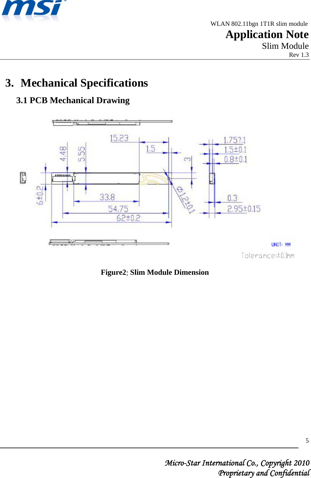
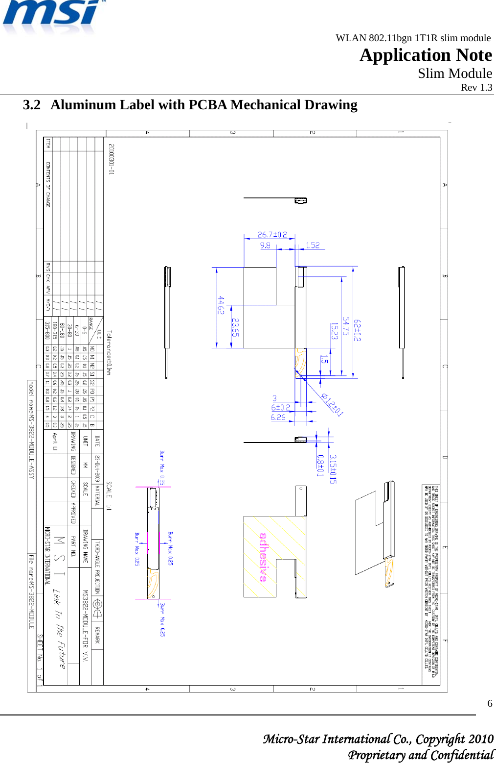
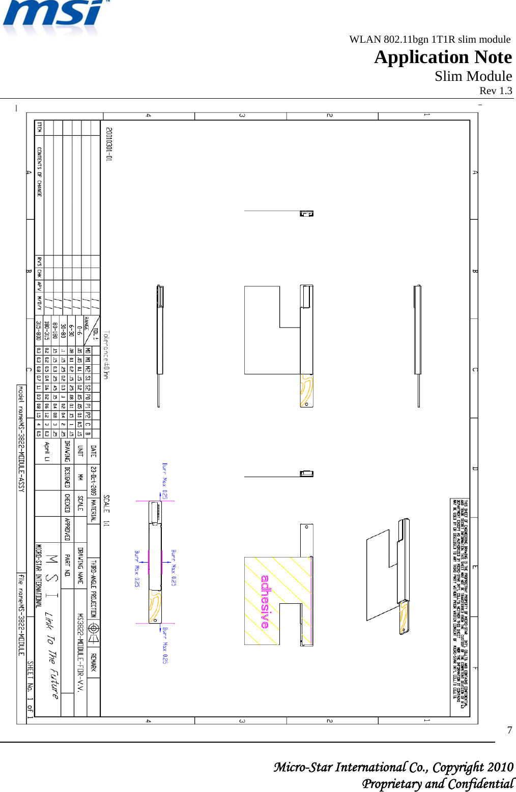
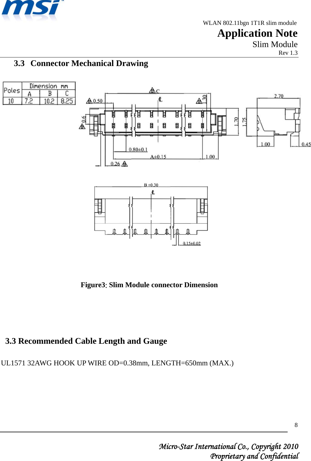
UserMan_I4L-MS3822_rev.

                                             WLAN 802.11bgn 1T1R slim module                                                         Application Note                                                       Slim Module                                                                            Rev 1.3   Micro-Star International Co., Copyright 2010  Proprietary and Confidential 1    APPLICATION NOTE  MS-3822  WLAN 802.11bgn 1T1R Slim Module
                                             WLAN 802.11bgn 1T1R slim module                                                         Application Note                                                       Slim Module                                                                            Rev 1.3   Micro-Star International Co., Copyright 2010  Proprietary and Confidential 2Revision History Revision  Date  Description  Author/Revised by 1.0 2010/02/22  First version  Benson 2.0 2010/4/14  Update PIN definition  Jackie 3.0  2010/5/12  Add foil dimension definition  Jackie
                                             WLAN 802.11bgn 1T1R slim module                                                         Application Note                                                       Slim Module                                                                            Rev 1.3   Micro-Star International Co., Copyright 2010  Proprietary and Confidential 31. Slim Module Block Diagram  Figure1: Slim Module Block Diagram
                                             WLAN 802.11bgn 1T1R slim module                                                         Application Note                                                       Slim Module                                                                            Rev 1.3   Micro-Star International Co., Copyright 2010  Proprietary and Confidential 42. Slim Module Pin Description  Table1: Slim Module Pin Description Pin  Name  Type  Description  Note 1  3.3V  P  3.3V from DC Power Supply Input for Module Circuits z Bypassing Capacitor Free z Ferrite Bead Free 2 NC    NC   3 NC    NC   4 NC    NC   5 GND  P  Ground   6  D+  I/O  D+ Line of USB2.0  WIFI D+ 7  D-  I/O  D- Line of USB2.0  WIFI D- 8 WI-FI_RADIO_OFF I/O  WI-FI_RADIO_OFF  Support System Module Turn radio ON/OFF WIFI Function (Never floating) WiFi on: High, off: Low 9  3.3V/Wi-Fi LED  P/I/O  3.3V from DC Power Supply /Wi-Fi LED  z Bypassing Capacitor Free z Ferrite Bead Free LED on: High, LED off: Low 10 GND  P  Ground     *Note:       (1)   I:   Input     (2)   O:   Output     (3)   I/O:  Bi-Direction     (4)   P:    Power
                                             WLAN 802.11bgn 1T1R slim module                                                         Application Note                                                       Slim Module                                                                            Rev 1.3   Micro-Star International Co., Copyright 2010  Proprietary and Confidential 5 3. Mechanical Specifications 3.1 PCB Mechanical Drawing  Figure2: Slim Module Dimension
                                             WLAN 802.11bgn 1T1R slim module                                                         Application Note                                                       Slim Module                                                                            Rev 1.3   Micro-Star International Co., Copyright 2010  Proprietary and Confidential 63.2  Aluminum Label with PCBA Mechanical Drawing
                                             WLAN 802.11bgn 1T1R slim module                                                         Application Note                                                       Slim Module                                                                            Rev 1.3   Micro-Star International Co., Copyright 2010  Proprietary and Confidential 7
                                             WLAN 802.11bgn 1T1R slim module                                                         Application Note                                                       Slim Module                                                                            Rev 1.3   Micro-Star International Co., Copyright 2010  Proprietary and Confidential 83.3  Connector Mechanical Drawing             Figure3: Slim Module connector Dimension     3.3 Recommended Cable Length and Gauge  UL1571 32AWG HOOK UP WIRE OD=0.38mm, LENGTH=650mm (MAX.)
                                             WLAN 802.11bgn 1T1R slim module                                                         Application Note                                                       Slim Module                                                                            Rev 1.3   Micro-Star International Co., Copyright 2010  Proprietary and Confidential 94. Recommended Assembly for Slim Module    Applying insulating tape or other insulator and adhere it onto the module or LCD panel. This is to prevent the module touching on the panel ground. (please note: This gap and insulating tap are necessary when the noise inducing from the LCD panel)    To achieve 40% antenna efficiency, Giving at least 5mm gap and applying insulating tap in between module & panel for better isolation.      5mm gap 5mm gap
                                             WLAN 802.11bgn 1T1R slim module                                                         Application Note                                                       Slim Module                                                                            Rev 1.3   Micro-Star International Co., Copyright 2010  Proprietary and Confidential 105. Solution for Thermal Reduction and Improving Antenna Gain     Adopting copper /aluminum foil or heat sink and then adhere it onto the top of slim module shielding case. The bigger the foil/heat sink, the better the thermal conduction.  Please note that the size of foil/heat sink should just fit properly onto the shielding case. Foil/ heat sink size larger than shielding area will impact the antenna performance. See below picture as a reference for correct cutting size. Copper foil is highly recommended as it will enhance antenna performance.
                                             WLAN 802.11bgn 1T1R slim module                                                         Application Note                                                       Slim Module                                                                            Rev 1.3   Micro-Star International Co., Copyright 2010  Proprietary and Confidential 116. Recommended Placement for Slim Module’s Antennas.  Leaving a gap between the slim module and NB housing ( the screw hole) for better antenna performance.  For Wi-Fi side, 20mm gap is recommended. Note: please avoid any metal parts to cover, touch or surround with antenna. Remark: If the webcam cable must go through MS-3822 module, please routing the top of panel edge and “flat cable” is the only solution to adopt.  Webcam cable (flat cable)  (Through the top of panel edge) 20mm GAP ( Wi-Fi)
                                             WLAN 802.11bgn 1T1R slim module                                                         Application Note                                                       Slim Module                                                                            Rev 1.3   Micro-Star International Co., Copyright 2010  Proprietary and Confidential 127. Recommended The Size of Copper /Aluminum Foil
                                             WLAN 802.11bgn 1T1R slim module                                                         Application Note                                                       Slim Module                                                                            Rev 1.3   Micro-Star International Co., Copyright 2010  Proprietary and Confidential 138. Recommended The EMI Coating Area We suggest the area of EMI Coating must be within the length of Green line: 92mm and the width between blue line A and B (from the end of panel to end of A side). Don't Coating exceed this area.
                                                                                 v1.0 U.S. Regulatory Wireless Notice Federal Communication Commission Interference Statement This equipment has been tested and found to comply with the limits for a Class B digital device, pursuant to Part 15 of the FCC Rules.  These limits are designed to provide reasonable protection against harmful interference in a residential installation. This equipment generates, uses and can radiate radio frequency energy and, if not installed and used in accordance with the instructions, may cause harmful interference to radio communications.  However, there is no guarantee that interference will not occur in a particular installation.  If this equipment does cause harmful interference to radio or television reception, which can be determined by turning the equipment off and on, the user is encouraged to try to correct the interference by one of the following measures:  - Reorient or relocate the receiving antenna. - Increase the separation between the equipment and receiver. - Connect the equipment into an outlet on a circuit different from that to which the receiver is connected. - Consult the dealer or an experienced radio/TV technician for help.  FCC Caution: Any changes or modifications not expressly approved by the party responsible for compliance could void the user's authority to operate this equipment.  This device complies with Part 15 of the FCC Rules. Operation is subject to the  following two conditions: (1) This device may not cause harmful interference, and (2)  this device must accept any interference received, including interference that may  cause undesired operation.    IMPORTANT NOTE: FCC Radiation Exposure Statement: This equipment complies with FCC radiation exposure limits set forth for an uncontrolled environment. This equipment should be installed and operated with minimum distance 20cm between the radiator & your body. This transmitter must not be co-located or operating in conjunction with any other antenna or transmitter.
                                                                                 v1.0  This device is intended only for OEM integrators under the following conditions: 1) The antenna must be installed such that 20 cm is maintained between the antenna and users, and  2) The transmitter module may not be co-located with any other transmitter or antenna,  3) For all products market in US, OEM has to limit the operation channels in CH1 to CH11 for 2.4G band by supplied firmware programming tool. OEM shall not supply any tool or info to the end-user regarding to Regulatory Domain change. As long as 3 conditions above are met, further transmitter test will not be required. However, the OEM integrator is still responsible for testing their end-product for any additional compliance requirements required with this module installed  IMPORTANT NOTE: In the event that these conditions can not be met (for example certain laptop configurations or co-location with another transmitter), then the FCC authorization is no longer considered valid and the FCC ID can not be used on the final product. In these circumstances, the OEM integrator will be responsible for re-evaluating the end product (including the transmitter) and obtaining a separate FCC authorization. IMPORTANT NOTE: In the event that these conditions can not be met (for example certain laptop configurations or co-location with another transmitter), then the FCC authorization is no longer considered valid and the FCC ID can not be used on the final product. In these circumstances, the OEM integrator will be responsible for re-evaluating the end product (including the transmitter) and obtaining a separate FCC authorization. End Product Labeling This transmitter module is authorized only for use in device where the antenna may be installed such that 20 cm may be maintained between the antenna and users. The final end product must be labeled in a visible area with the following: “Contains FCC ID: I4L-MS3822”. Manual Information To the End User The OEM integrator has to be aware not to provide information to the end user regarding how to install or remove this RF module in the user’s manual of the end product which integrates this module. The end user manual shall include all required regulatory information/warning as show in this manual.   Canadian Regulatory Wireless Notice This device complies with RSS-210 of the Industry Canada Rules. Operation is subject to the following two conditions: 1) this device may not cause interference and 2) this device must accept any interference, including interference that may cause undesired operation of the device
                                                                                 v1.0 IMPORTANT NOTE: IC Radiation Exposure Statement: This equipment complies with IC radiation exposure limits set forth for an uncontrolled environment. This equipment should be installed and operated with minimum distance 20cm between the radiator and your body.  This device is intended only for OEM integrators under the following conditions:  1) The antenna must be installed such that 20 cm is maintained between the antenna  and users, and  2) The transmitter module may not be co-located with any other transmitter or antenna,  3) For all products market in Canada, OEM has to limit the operation channels in CH1 to  CH11 for 2.4G band by supplied firmware programming tool. OEM shall not supply  any tool or info to the end-user regarding to Regulatory Domain change. As long as 3 conditions  above are met, further transmitter test will not be required. However, the OEM integrator is still responsible for testing their end-product for any additional compliance requirements required with this module installed (for example, digital device emissions, PC peripheral requirements, etc.).  MPORTANT NOTE: In the event that these conditions cannot be met (for example certain laptop  configurations or co-location with another transmitter), then the IC authorization is no longer considered valid and this ID cannot be used on the final product. In these circumstances, the OEM integrator will be responsible for re-evaluating the end product (including the transmitter) and obtaining a separate Canada IC authorization  End Product Labeling  This transmitter module is authorized only for use in device where the antenna may be installed such that 20 cm may be maintained between the antenna and users. The final end product must be labeled in a visible area with the following: “Contains IC: 3715A-MS3822.   Manual Information To the End User  The OEM integrator has to be aware not to provide information to the end user regarding how to install or remove this RF module in the user’s manual of the end product which integrates this module. The end user manual shall include all required regulatory information/warning as show in this manual.

Navigation menu