Micro Star MS6837D6 Notebook User Manual 01 1719v1 0 Generic MANUAL EN Introductions
Micro Star International Co Ltd Notebook 01 1719v1 0 Generic MANUAL EN Introductions
UserManual.wiki
>
Micro Star
>
MS6837D6 User Manual
User manual
Navigation menu
Upload a User Manual
Namespaces
Wiki Guide
HTML
PDF
Info
Views
User Manual
Discussion / Help
Navigation

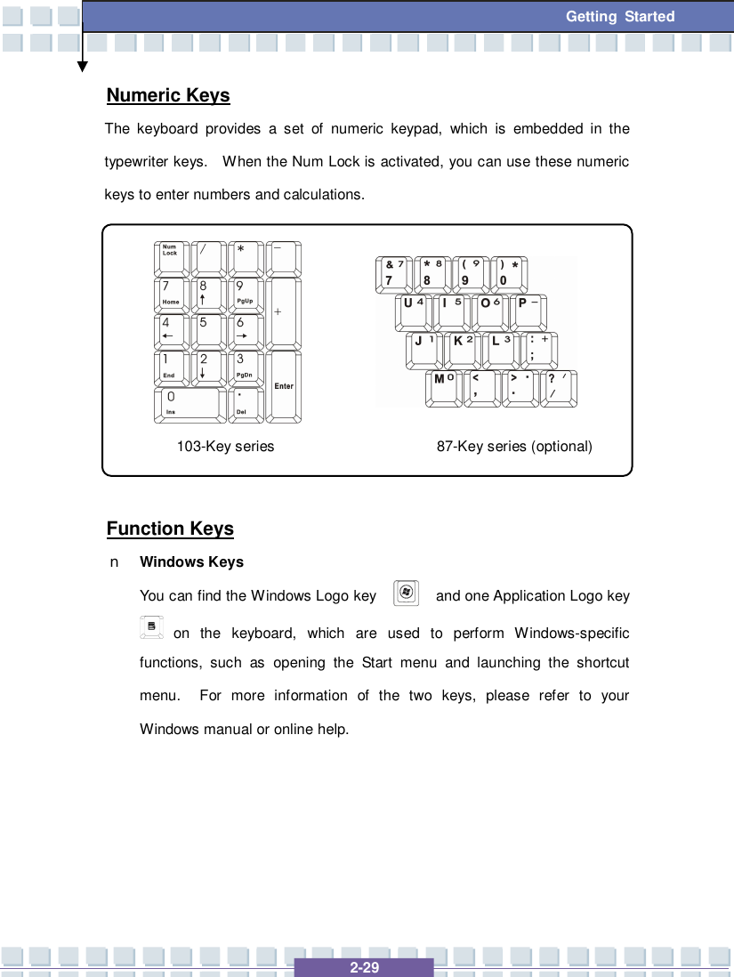
![2-25 Getting Started Knowing the Keyboard The Notebook’s keyboard provides all the functions of a full-sized keyboard and an additional [Fn] key for specific functions on the Notebook. The keyboard can be divided into four categories: Typewriter keys, Cursor keys, Numeric keys and Function keys. 103-Key series 87-Key series (optional)](https://usermanual.wiki/Micro-Star/MS6837D6/User-Guide-810448-Page-56.png)
![2-26 Getting Started Typewriter Keys The function of these Typewriter keys is the major function of the keyboard, which is similar to the keys on a typewriter. It also provides several keys for special purposes, such as the [Ctrl], [Alt] and [Esc] key. When the lock keys are pressed, the corresponding LEDs will light up to indicate their status: n Num Lock: Press and hold the [Fn] key and press this key to toggle the Num Lock on and off. When this function is activated, you can use the numeric keys that are embedded in the typewriter keys. n Caps Lock: Press this key to toggle the Caps Lock on and off. When this function is activated, the letters you type are kept in uppercase. n Scroll Lock: Press and hold the [Fn] key and press this key to toggle the Scroll Lock on and off. This function is defined by individual programs, 87-Key series (optional) 103-Key series](https://usermanual.wiki/Micro-Star/MS6837D6/User-Guide-810448-Page-57.png)
![2-27 Getting Started and it is usually used under DOS. Cursor Keys The keyboard provides four cursor (arrow) keys and [Home], [PgUp], [PgDn], [End] keys at the lower right corner, which are used to control the cursor movement. Move the cursor left for one space. Move the cursor right for one space. Move the cursor up for one line. Move the cursor down for one line. 103-Key series 87-Key series (optional)](https://usermanual.wiki/Micro-Star/MS6837D6/User-Guide-810448-Page-58.png)
![2-28 Getting Started + Move to the previous page. + Move to the next page. Move to the beginning of the line (or document). Move to the end of the line (or document). The Backspace key, [Ins] and [Del] keys at upper right corner are use for editing purpose. This key is used to switch the typing mode between “insert” and “overtype” modes. Press this key to delete one character to the right of the cursor and move the following text left for one space. Press this key to delete one character to the left of the cursor and move the following text left for one space.](https://usermanual.wiki/Micro-Star/MS6837D6/User-Guide-810448-Page-59.png)
![2-30 Getting Started n [Fn] Key + Switch the display output mode between the LCD, external monitor and Both. + Enable or disable the touchpad function. + Decrease the LCD brightness. + Increase the LCD brightness. + Decrease the built-in speaker’s volume. + Increase the built-in speaker’s volume. + Disable the computer’s audio function. + Force the computer into suspend mode (depending on the system configuration).](https://usermanual.wiki/Micro-Star/MS6837D6/User-Guide-810448-Page-61.png)
![3-5 Customizing this Notebook 2. Plug the monitor’s D-type connector into the Notebook’s VGA port. 3. Connect the monitor’s power cord and turn on the monitor. 4. Turn on the Notebook and the monitor should respond by default. If not, you can switch the display mode by pressing [Fn]+[F2]. Alternately, you can change the display mode by configuring the settings in Display Properties of Windows operating system. Connecting the IEEE 1394 devices The IEEE 1394 port of your Notebook is a next-generation serial bus that features a high-speed transfer rate and the connection of up to 63 devices, allowing you to connect many high-end peripheral devices and consumer electronic appliances, such as the DV (digital video camera). The IEEE 1394 standard interface supports “plug-and-play” technology, so that you can connect and remove the IEEE 1394 devices without turning off the Notebook. To connect the IEEE 1394 device, simply connect the cable of the device to the IEEE 1394 port of your Notebook.](https://usermanual.wiki/Micro-Star/MS6837D6/User-Guide-810448-Page-74.png)
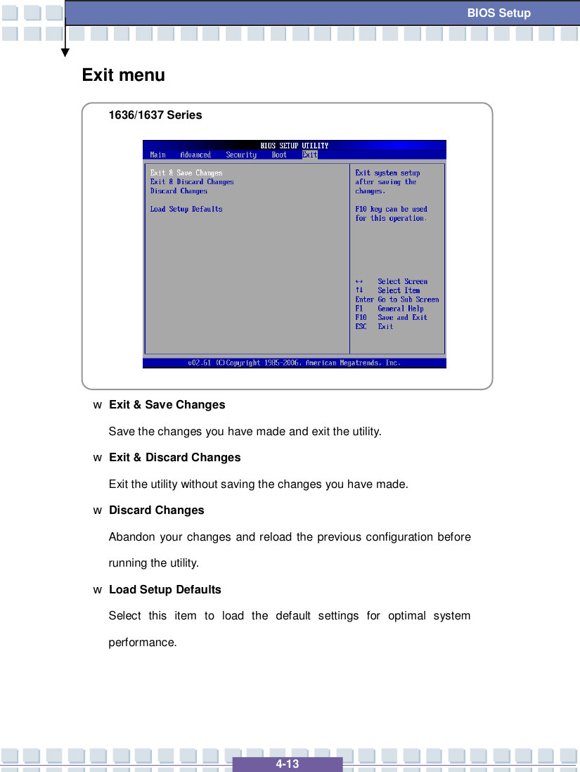
![4-2 BIOS Setup About BIOS Setup When to Use BIOS Setup? You may need to run the BIOS Setup when: w An error message appears on the screen during the system booting up and requests you to run SETUP. w You want to change the default settings for customized features. w You want to reload the default BIOS settings. How to Run BIOS Setup? To run the BIOS Setup Utility, turn on the Notebook and press the [Del] key during the POST procedure. If the message disappears before you respond and you still wish to enter Setup, restart the system by turning it OFF and ON, or simultaneously pressing [Ctrl]+[Alt]+[Delete] keys to restart. The screen snaps and setting options in this chapter are for your references only. The actual setting screens and options on your Notebook may be different because of BIOS update.](https://usermanual.wiki/Micro-Star/MS6837D6/User-Guide-810448-Page-80.png)
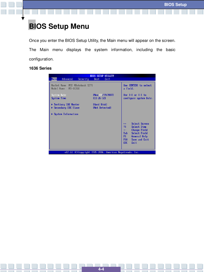
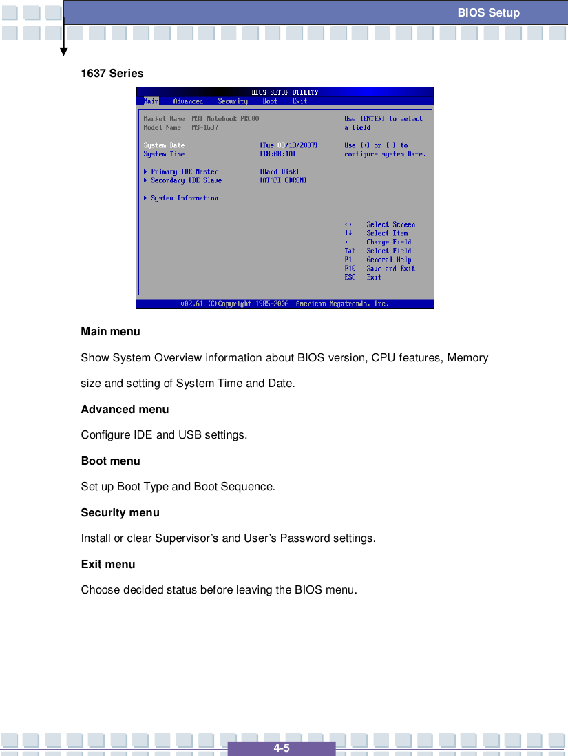
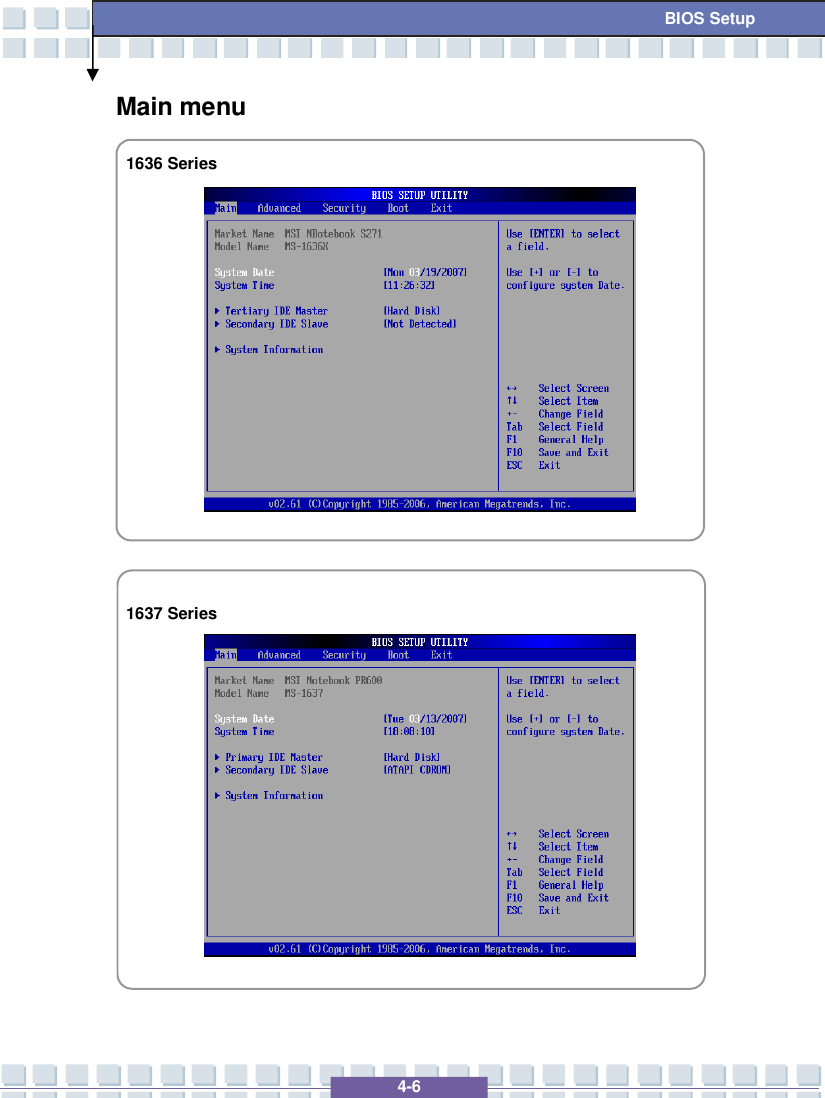
![4-7 BIOS Setup System Overview System Overview will show you BIOS version and other information about its build date and update notes. Following is CPU’s information about its Type and Speed. w System Time This item allows you to set the system time. The system clock will go on no matter you shut down the PC or get into sleep mode. The set format is [hour:minute:second]. w System Date This item allows you to set the system date. The date format is [day:month:date:year]. Day Day of the week, from Sun to Sat, which is determined by BIOS (read-only). Month The month from 01 (January) to 12 (December). Date The date from 01 to 31. Year The year can be adjusted by users. w Primary/Secondary IDE Master/Slave The two items display the types of the primary/secondary IDE master/slave devices installed in the Notebook. Press [Enter] to bring up a window showing the detailed information of the device, including the device name, vendor, LBA mode, PIO mode and more. w System Information This item indicates the information of firmware, processor, and system memory.](https://usermanual.wiki/Micro-Star/MS6837D6/User-Guide-810448-Page-85.png)
![4-11 BIOS Setup Security menu 1636/1637 Series Security Settings w Change Supervisor/User Password When you select the function, a message box will appear on the screen as below: Type the password you want, up to six characters in length and press [Enter]. The password typed now will replace any previously set password from CMOS memory. You may also press [ESC] to abort the selection and not enter a password. Enter New Password](https://usermanual.wiki/Micro-Star/MS6837D6/User-Guide-810448-Page-89.png)
![4-12 BIOS Setup When the Supervisor Password is set, the new item User Access Level and Password Check will be added in the menu. You can make further settings of access right in the User Access Level item. Setting options: No Access, View Only, Limited and Full Access. The Password Check item is used to specify the type of BIOS password protection that is implemented. Settings are described below: Setup The password prompt appears only when end users try to run Setup. Always A password prompt appears every time when the Notebook is powered on or when end users try to run Setup. To clear a set password, just press [Enter] when you are prompted to enter the password. A message box will show up confirming the password will be disabled. Once the password is disabled, the system will boot and you can enter Setup without entering any password. About Supervisor Password and User Password Supervisor Password allows the user to enter and change the settings of the setup menu; User Password only allows the user to enter the setup menu, but do not have the right to make changes.](https://usermanual.wiki/Micro-Star/MS6837D6/User-Guide-810448-Page-90.png)