Micro Star MS6837D7 Notebook User Manual 01 1719v1 0 Generic MANUAL EN Introductions
Micro Star International Co Ltd Notebook 01 1719v1 0 Generic MANUAL EN Introductions
Users manual

(MS-6837D)
Bluetooth 2.0+EDR USB
Module
User’s Guide
FEDERAL COMMUNICATIONS COMMISSION INTERFERENCE STATEMENT
This equipment has been tested and found to comply with the limits for a Class B digital
device, pursuant to Part 15 of the FCC Rules. These limits are designed to provide
reasonable protection against harmful interference in a residential installation. This
equipment generates, uses and can radiate radio frequency energy and, if not installed
and used in accordance with the instructions, may cause harmful interference to radio
communications. However, there is no guarantee that interference will not occur in a
particular installation. If this equipment does cause harmful interference to radio or
television reception, which can be determined by turning the equipment off and on, the
user is encouraged to try to correct the interference by one or more of the following
measures:
– Reorient or relocate the receiving antenna.
– Increase the separation between the equipment and receiver.
– Connect the equipment into an outlet on a circuit different from that to which the
receiver is connected.
– Consult the dealer or an experienced radio/TV technician for help.
CAUTION:
Any changes or modifications not expressly approved by the party responsible for
compliance could void the user's authority to operate the equipment.
This device complies with Part 15 of the FCC Rules. Operation is subject to the following
two conditions:
(1) This device may not cause harmful interference and
(2) This device must accept any interference received, including interference that may
cause undesired operation.
FCC RF Radiation Exposure Statement
This equipment complies with FCC RF radiation exposure limits set forth for an
uncontrolled environment.
This equipment must not be co-located or operating in conjunction with any other antenna
or transmitter.
Important Note
In the event that these conditions can not be example certain laptop configurations or
colocation
with another transmitter), then the FCC authorization is no longer considered valid the FCC
ID can not be used on the final product. In these circumstances, OEM integrator will be
responsible for re-evaluating the end product (including thetransmitter) and obtaining a
separate FCC authorization.

End
Product
Labelin
g
This transmitter module is authorized only for use in device where antenna may b
e
installed such that 2.5 cm may be maintained between antenna and users (for
example
access points, routers, wireless ADSL and similar equipment). The final end produc
t
must be labeled in a area with the following: “ Contains TX FCC ID: I4L-MS6837D7”.
Manual
Information
for
End
User
s
The end user must not have manual instructions to remove or install device. The
user manual for end users must include the following information in a prominent
location:
“IMPORTANT NOTE: To comply with FCC RF exposure compliance requirements
,
the antenna used for this transmitter must be installed to provide a separation distance
of
at least 20 cm from all persons and must not be co-located operating in conjunction
with
any other antenna or transmitter.” as a result of e-mail transmission.”
Important
Safety
Precaution
s
Always
read and follow these basic safety precautions carefully when handling any
piece of electronic component.
1. Keep this User’s Guide for future reference.
2. Keep this equipment away from humidity.
3. Lay this equipment on a reliable flat surface before setting it up.
4. The openings on the enclosure are for air convection hence protects the
equipment from overheating.
5. All cautions and warnings on the equipment should be noted.
6. Never pour any liquid into the opening that could damage or cause electrical
shock.
7. If any of the following situations arises, get the equipment checked by a
service personnel:
Liquid has penetrated into the equipment
The equipment has been exposed to moisture
The equipment has not work well or you can not get it work
according to User’s Manual
The equipment has dropped and damaged
If the equipment has obvious sign of breakage
8. DO NOT LEAVE THIS EQUIPMENT IN AN ENVIRONMENT
UNCONDITIONED, STORAGE TEMPERATURE ABOVE 70O C OR
BELOW -35OC, IT MAY DAMAGE THE EQUIPMENT.
ii
i

Introduction
>>>
1.1
BT2RM
(MS
-
6837D
)
Bluetooth Module
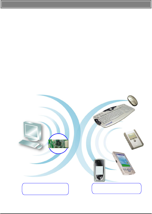
MSI Bluetooth 2.0+EDR USB module, BT2RM, is a USB
1.1 Full Speed Module compatible with USB 2.0, being
used to integrate with systems such as notebook, Barebone
computer, PDA, portable PC, Smart Phone. With MSI
BT2RM
embedded inside, a system could provide users with
the ability and flexibility to link with peripherals wirelessly
through EDR (Enhanced Data Rate) technology in
Bluetooth v2.0+EDR speeding up to 3Mbps, advanced AFH
(Adaptive Frequency Hopping) techniques in Bluetooth v1.2
to minimize interference and enhance performance when
linking with Bluetooth v1.1 devices and eSCO (extended
SCO) techniques in Bluetooth v1.2 optional supported for
enhancing the audio performance.
1
>>>
1.2
How
BT2RM
Work
s
2
BT2RM
Bluetooth
Module
Bluetooth
-
enabled
Device
s
1.2.
1
In
Bluetooth
Connectio
n
The term “Bluetooth” refers to a worldwide standard for th
e
wireless exchange of data between two devices. In order to ex
-
change data, two Bluetooth devices must establish a
connection.
Before a connection is established, one device must request
a
connection with another. The second device accepts (or
rejects)
the connection. The originator of the request is known
as
the client. The device that accepts (or rejects) the request
is
known as the server. Many Bluetooth devices can act as
both
client and
server. Every Bluetooth device that provides a
service must be prepared to respond to a connection
request.
Bluetooth soft- ware is always running in the background on
the
server, ready to respond to connection requests.

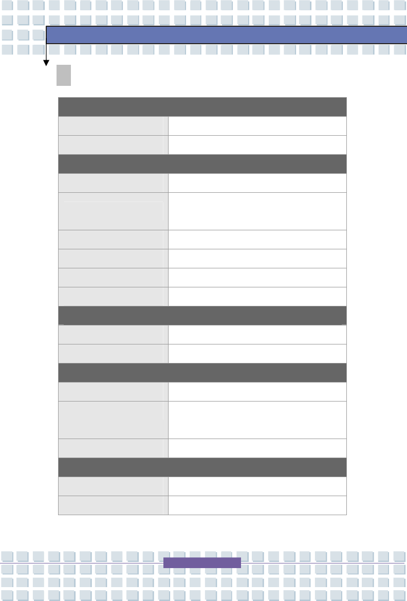
Bluetooth Specifications
Radio Standard Bluetooth Class II v2.0+EDR
Frequency Band 2.400-2.4835 GHz
Data Rate Up to 2169kbps
Channel 79 sub-channels
Transmission FHSS (Frequency Hopping
Spread Spectrum)
Modulation GFSK@1Mbps, π/4
DQPSK@2Mbps,
8DPSK@3Mbps
Antenna Type Printed Circuit Antenna or
One antenna connector
support
Operating
Temperature
-35° to 70°C Temperature
Storage
Temperature
-20° to 70°C
Humidity 10%-90% (non-condensing)
Power Consumption 61.37mA in continue Tx
12mA in Standby mode
Output Power 0~4dBm
Max Input Level 0dBm
Receiver Sensitivity -82 dBm @ BER<0.1%
Range Up to 10m operating range
Baseband
Physical Links Support ACL and SCO link
Network Capabilities
Support piconet point-to-
point and point-to-multipoint
connections
3
>>>
1.3
Specification
s

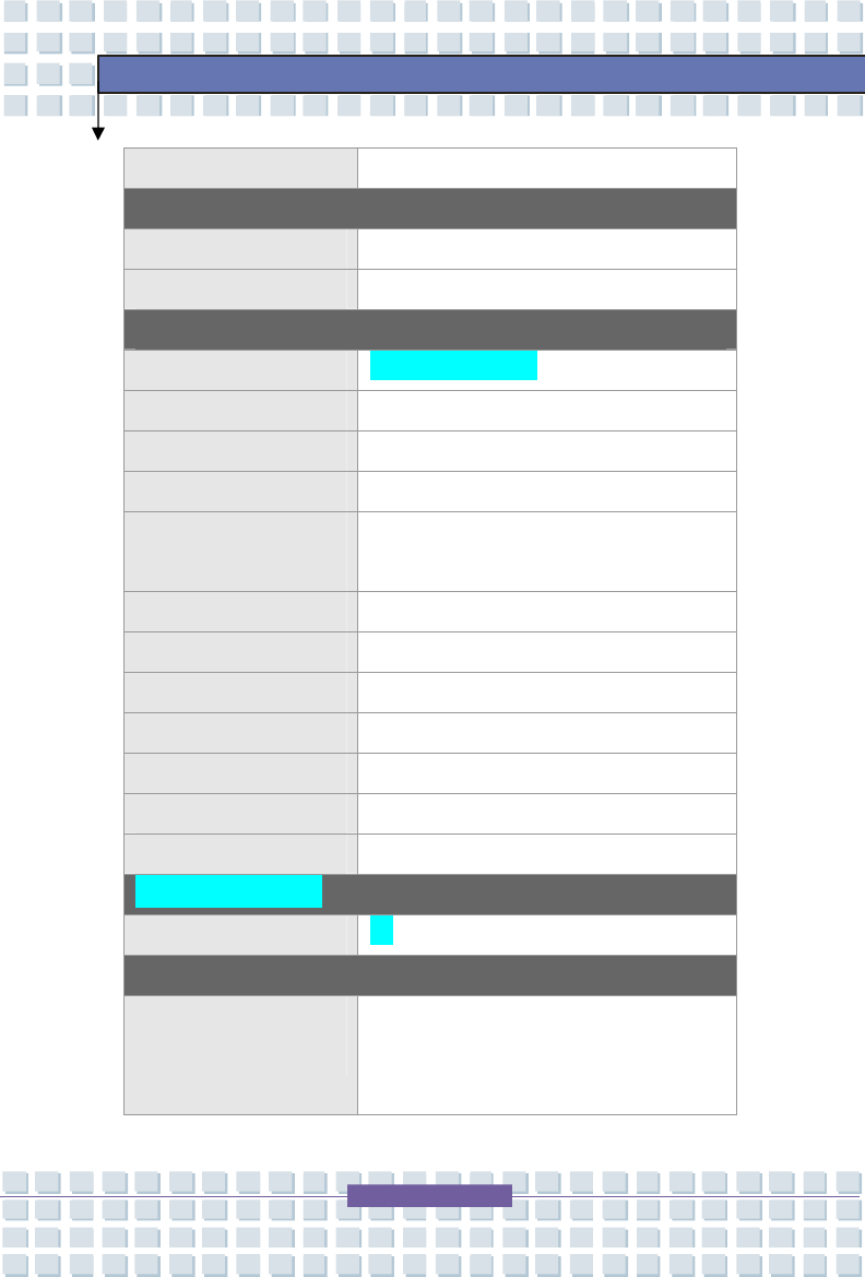
Link Manager
3-slot Packets Yes
5-slot Packets Yes
Slot Offset Yes
Timing Accuracy Yes
Switch Yes
Hold Mode Yes
Sniff Mode Yes
Test Mode Yes
Park Mode Yes
RSSI Yes
Power Control Yes
Authentication Yes
Encryption Yes
System Support Windows® 2000/ME/98SE/XP
Profile Support
Generic Access Profile/Service
Discovery Profile/Serial Port
Profile/Dial-Up Networking
Profile/Fax Profile/LAN Access
Profile/Generic Object Exchange
Profile/File Transfer Profile/Object
Push Profile/Synchronization
Profile/Personal Area Network
Profile/Hard Cable Replacement
Profile/Basic Image Profile/Generic
Audio Video Distribution
Profile/Advanced Audio Distribution
Profile/Audio Video Remote Control
Profile
4
>>>
1.4
System
Requirement
s
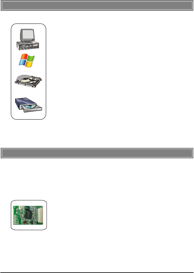
Before installing BT2RM, your PC should meet the following
items:
-
One desktop/notebook PC with an available Min
iPCI slot.
-
Windows
®
98SE/ME/2000/XP operating system.
-
Minimum
5MB
free
disk
space
for
installing
the
driver
and
utilities.
-
One CD
-
ROM drive, double speed or higher.
>>>
1.5
Package
Content
s
Unpack the package and check all the items carefully. If any
item
contained is damaged or missing, please contact your local
dealer
as soon as possible. Also, keep the box and packing materials
in
case you need to ship the unit in the future. The package
should
contain
the
f
ollowing
items:
-
One
Bluetooth module
.
5
>>>
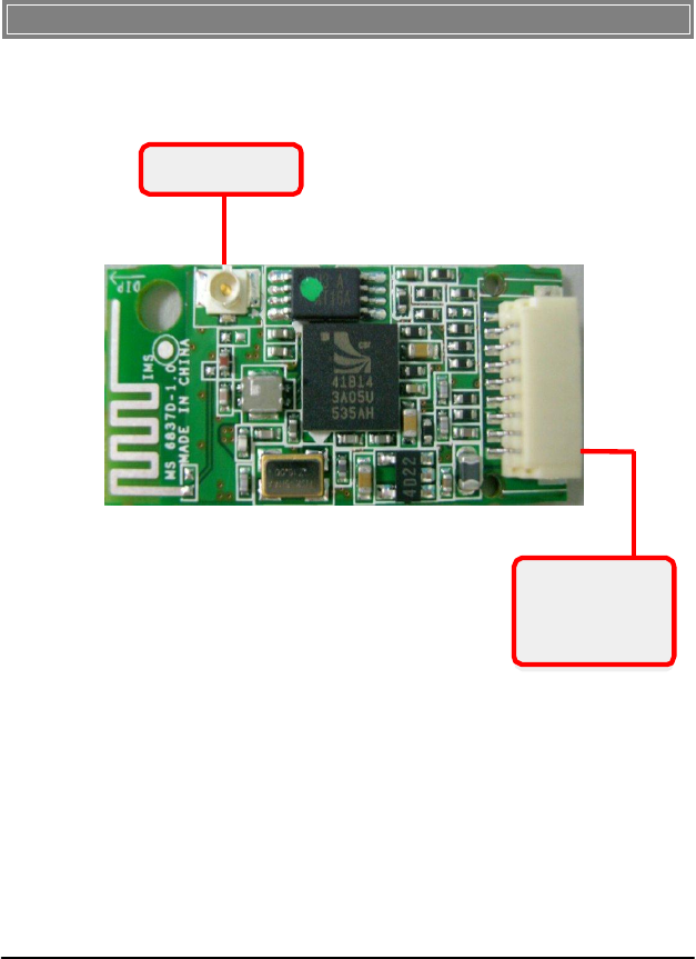
1.6
Product
Vie
w
Bluetooth
antenn
a
Connecto
r
USB
Connecto
r
Connect to
your notebook
using the provided
USB cable.
6
The following diagrams provide you a basic installation for
your
BT2RM . The instruction below is suitable for most com
-
puters with USB slot. For more information about the
USB
module, please refer to your computer’s manual.
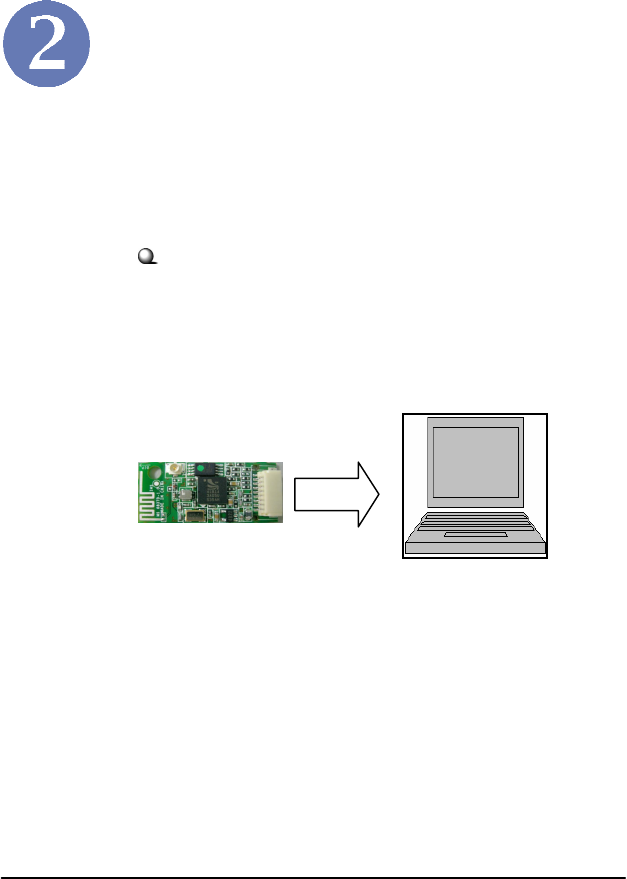
Hardware
Installation
Installing BT2RM:
1. Connect one end of the USB cable to the eight
-pin USB connector on BT2RM , and
the other end to the USB connector located on
your notebook.
7
Software
Installatio
n
This chapter describes the procedures of installing the driver
and utility. Follow the instruction step by step to finish
the installation. If you use Windows® 98SE/ME, please
prepare the Windows® Setup CD at hand before installing the
driver; because the system will ask you to insert the Setup CD
to copy files during the installation.
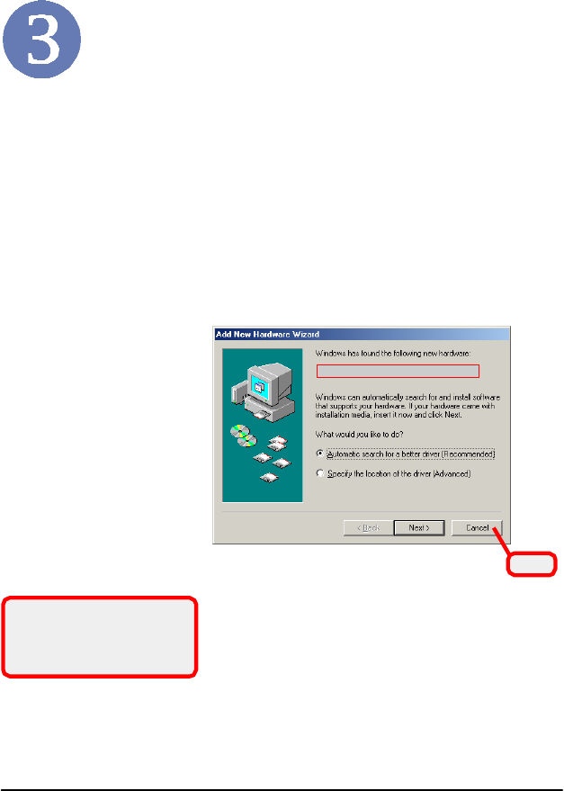
Please
NOT
E
that the
BT2RM
should be installed int
o
your computer before installing the driver and utility
.
Then, the operating system will detect a new device and
start
to con- figure the new device. Click Cancel here to
start
installation from the InstallShield Wizard.
The
adapter
model
you
installe
d
Clic
k
Tip: The
BT2RM
adapte
r
should be installed into your P
C
before installing the driver an
d
utility
.
8
STEP
1
Insert the software CD into your CD-ROM drive, and the Setup
program should launch automatically.
If the Autorun program doesn’t launch automatically, click Star
t
at the taskbar and select Run.... Type E:\setup.exe (where
E
is your CD-drive) in the Open box and click OK to
launch
the Setup program manually.
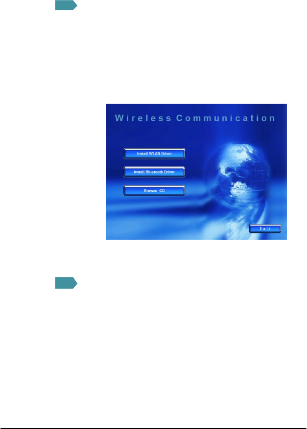
The
main
screen
of
Set
up
program
will
appear
as
below
.
STEP
2
9
1
.
Clic
k
th
e
Install
Bluetooth
Drive
r
button
.
2.The welcome screen of InstallShield Wizard appears.
Click Next.
3.Read and accept the License Agreement; then, click Next.
4.Click Next to install the driver in the default destination
folder.
5.Click Install and the program will copy the necessary
files to the system. The progress indicator shows the
installing status.
6.Click Finish when the bluetooth driver installation is
completed.

STEP
3
Bluetooth
ico
n
10
Click
th
e
Exi
t
button
.
The Wireless LAN icon and Bluetooth icon will appear in th
e
status bar.
FEDERAL COMMUNICATIONS COMMISSION INTERFERENCE STATEMENT
This equipment has been tested and found to comply with the limits for a Class B digital
device, pursuant to Part 15 of the FCC Rules. These limits are designed to provide
reasonable protection against harmful interference in a residential installation. This
equipment generates, uses and can radiate radio frequency energy and, if not installed
and used in accordance with the instructions, may cause harmful interference to radio
communications. However, there is no guarantee that interference will not occur in a
particular installation. If this equipment does cause harmful interference to radio or
television reception, which can be determined by turning the equipment off and on, the
user is encouraged to try to correct the interference by one or more of the following
measures:
– Reorient or relocate the receiving antenna.
– Increase the separation between the equipment and receiver.
– Connect the equipment into an outlet on a circuit different from that to which the
receiver is connected.
– Consult the dealer or an experienced radio/TV technician for help.
CAUTION:
Any changes or modifications not expressly approved by the party responsible for
compliance could void the user's authority to operate the equipment.
This device complies with Part 15 of the FCC Rules. Operation is subject to the following
two conditions:
(1) This device may not cause harmful interference and
(2) This device must accept any interference received, including interference that may
cause undesired operation.
FCC RF Radiation Exposure Statement
This equipment complies with FCC RF radiation exposure limits set forth for an
uncontrolled environment.
This equipment must not be co-located or operating in conjunction with any other antenna
or transmitter.
General Introductions Chapter 1
Getting Started
Chapter 2
Customizing this Notebook
Chapter 3
BIOS setup
Chapter 4
Preface
1
-
2
General Introductions
Congratulations on becoming a new user of this notebook, the finely designed
notebook. This brand-new exquisite notebook will give you a delightful and
professional experience in using notebook. We are proud to tell our users that
this notebook is thoroughly tested and certified by our reputation for
unsurpassed dependability and customer satisfaction.
How to Use This Manual
This User’s Manual provides instructions and illustrations on how to operate this
notebook. It is recommended to read this manual carefully before using this
notebook.
Chapter 1, General Introductions, includes the descriptions of all the
accessories of this notebook. It is recommended to check out that if you have
all the accessories included when you open the packing box. If any item is
damaged or missing, please contact the vendor where you purchased this
notebook.
Chapter 2, Getting Started, provides the specification of this notebook, and
introduces the function buttons, quick launch buttons, connectors, LEDs and
externals of this notebook. Also, this chapter instructs the correct procedure of
installing or uninstalling the battery pack, and the brief ideas on how to use this
notebook.
1
-
3
General Introductions
Chapter 3, Customizing this Notebook, gives instructions not only in
connecting the mouse, keyboard, webcam, printer, external monitor, IEEE 1394
devices, and communication devices, but also in installing and removing the PC
card.
Chapter 4, BIOS setup, provides information on BIOS Setup program and
allows you to configure the system for optimum use.

1
-
4
General Introductions
Unpacking
First, unpack the shipping carton and check all items carefully. If any item
contained is damaged or missing, please contact your local dealer immediately.
Also, keep the box and packing materials in case you need to ship the unit in the
future.
The package should contain the following items:
w Notebook
w User’s Manual or Quick Start Guide
w All-in-one application disk, containing the drivers, utilities, and optional
recovery function.
w High-capacity Li-ion battery pack
w AC adapter and power cord
w Phone cable/Phone jack (optional)
w Notebook carry bag (optional)
These accessories listed above may change without notice.

)
General Introductions Chapter 1
Getting Started
Chapter 2
Customizing this Notebook
Chapter 3
BIOS setup
Chapter 4
Preface
2-2
Getting Started
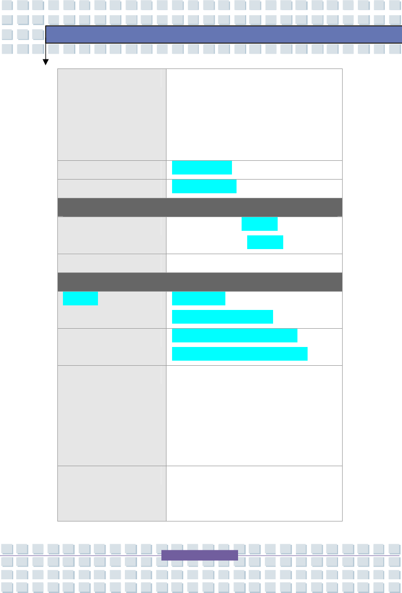
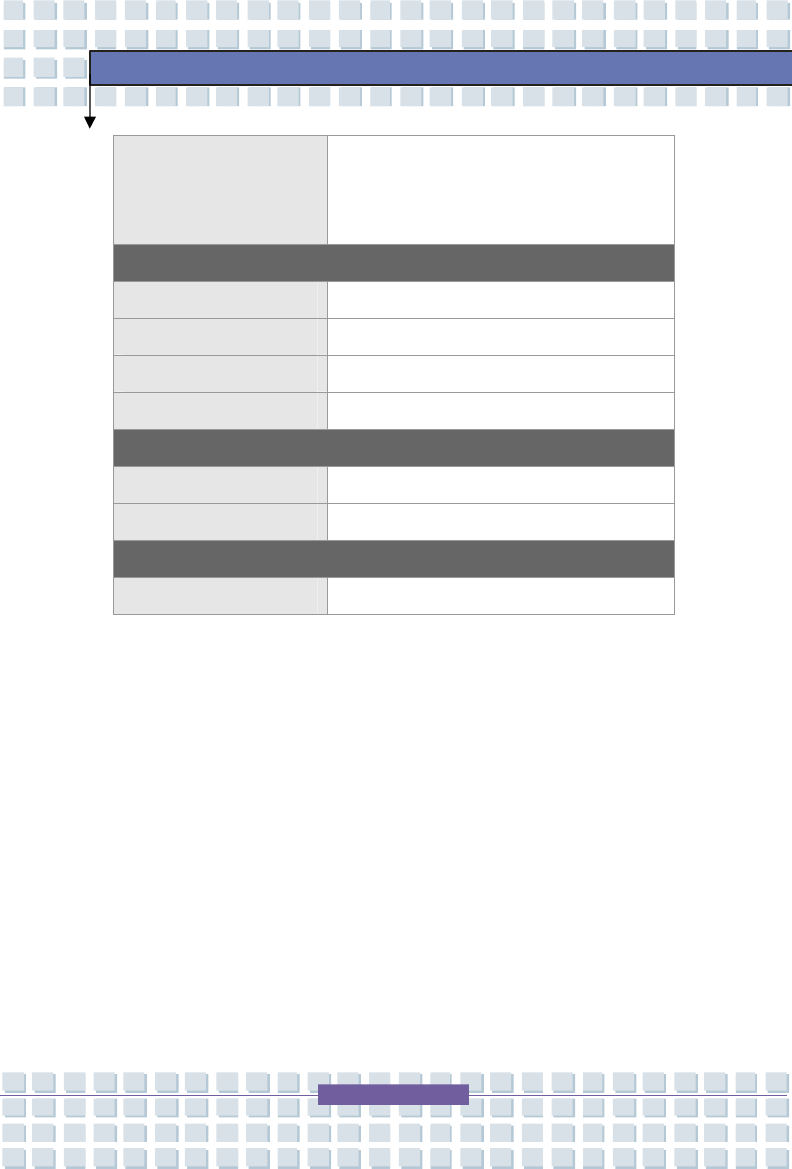
Specification
Physical Characteristic
Dimension 395mm(L) x 278mm(D) x 26.5~34.9mm(H)
Weight 3.6kg with 6 cell battery
CPU
Processor Type Socket 478
Support Processor Intel Santa Rosa plateform/Meron
Processor (dual core)
L1 Cache 64KB
L2 Cache 4MB
Socket 478 pins
FSB Speed 800MHz
Core Chips
North Bridge Intel 965PM
South Bridge Intel ICH8-M
Memory
Technology DDR2 533/667 MHz
Memory DDR2 SO-DIMM X 2 slot
256/512/1024MB DDR2 SDRAM
Maximum 2GB (1024MB DDRII SO-DIMM X 2)
Power
AC Adapter 90W, 19 Volt
Battery Type 6 cells(Li-ion) (standard) (4400mAH) /
2-3
Getting Started
9 cells (Li-ion) (optional) (7200mAH)
Storage
HDD form factor 2.5” 9.5mm High, 5400rpm
Optical Device DVD super multi, light scribe
I/O Port
Monitor(VGA) 15 pin Mini D-Sub x 1
USB x 3 (USB version 2.0)
Mic-In x 1
Line-In x 1
Headphone Out/
SPDIF Out
x 1
RJ11 x 1
RJ45 x 1
IEEE 1394 x 1
TV-Out x 1 (HDMI)
Card Reader XD/ MMC/MS 3-in-1 card reader x 1
PCMCIA slot x 1
Express Card slot x 1
Camera (optional)
x 1
Communication Port
56K Fax/MODEM
Wake on Ring --- Support on S3/S4 (AC
mode) state
PTT Approval --- Yes (FCC/CTR21/JATE)
2-4
Getting Started
LAN PCI-E LAN --- 10/100/1000 Base on board
LAN
Wake on LAN --- Support on S3/S4/S5 state
LAN Boot --- Yes
Wfm --- Wfm 2.0 support
Wireless LAN IEEE 802.11b/g
Bluetooth Support (optional)
Display
LCD Type 17” WXGA + Glare/non-Glare Type or
17” WSXGA + Glare/non-Glare Type
Brightness Brightness controlled by K/B hot-keys
Video
Controller 1. Main stream
2. NVIDIA NB8PGS, 512MB
LCD 1440 x 900 for WXGA+, Glare type
1680 x 1050 for WSXGA+, Glare type
Display Detect System auto detects LCD or CRT:
1. Display to CRT - only if LCD lid is
closed;
2. Display to LCD - only if no CRT
detected;
3. Display can scan CRT & LCD
simultaneously if both are detected and
activate.
CRT Support 640x480, max, 32bit color
800x600, max, 32bit color
1024x768, max, 32bit color
2-5
Getting Started
1152 x 768, max 32bit color
1400x1050, max, 32bit color
1600 x 1200, max.32bit color
Audio
Sound Codec chip Embeded in Sourth Bridge
Internal Microphone x 1
Internal Speaker 4 Speakers with housing
Sound Volume Adjust by volume button, K/B hot-key & SW
Software & BIOS
USB Flash Boot Yes, USB floppy boot up DOS only
BIOS Fast Boot Support --- Yes
Others
Kensington Lock Hole x 1
2-6
Getting Started
Product Overview
This section provides the description of basic aspects of your notebook. It will
help you to know more about the appearance of this notebook before using it.
Note: The notebook shown here may vary from the actual one.
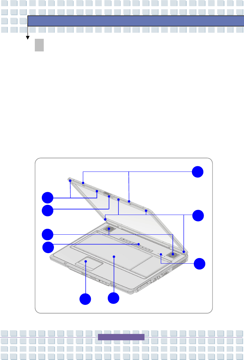
Top-open View
Press the Cover Latch to open the top cover (LCD Panel). The figure of top-open
view and description showing below will lead you to browse the main operating
area of your notebook.
2
1
3
4
5
6
7
2
8
2-7
Getting Started
1. Cover Latch (Internal View)
It is a bounce-back device to lock the cover with the deck when closing
your notebook.
2. Rubber Pads
Protect your notebook from random closing.
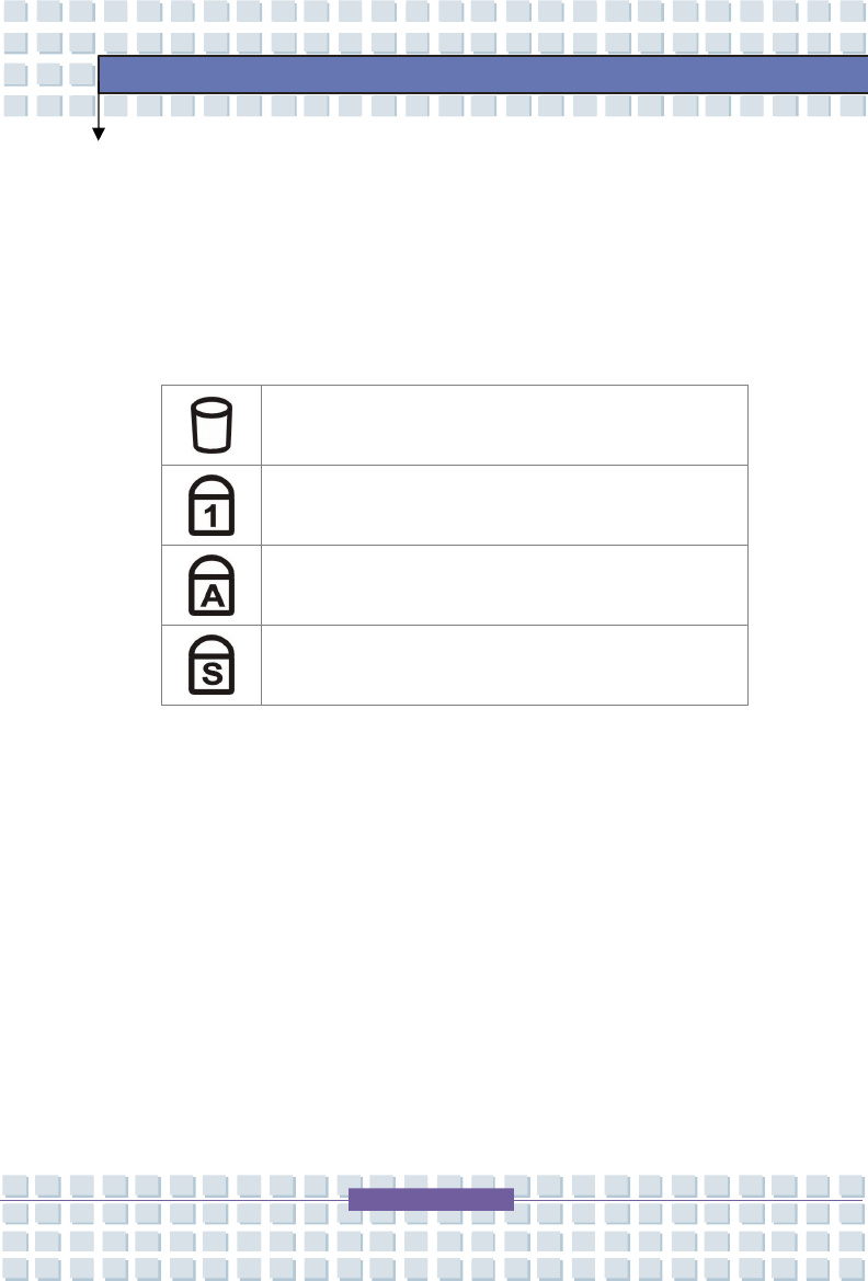
3. Status LED
Hard Disk In-use: Blinking Red when the notebook is
accessing the hard disk drive.
Num Lock: Glowing Green when the Num Lock function is
activated.
Caps Lock: Glowing Green when the Caps Lock function is
activated.
Scroll Lock: Glowing Green when the Scroll Lock function
is activated.
4. Keyboard
The built-in keyboard provides all the functions of a full-sized (US-defined)
keyboard.
5. Touchpad
It is the pointing device of the computer..
2-8
Getting Started
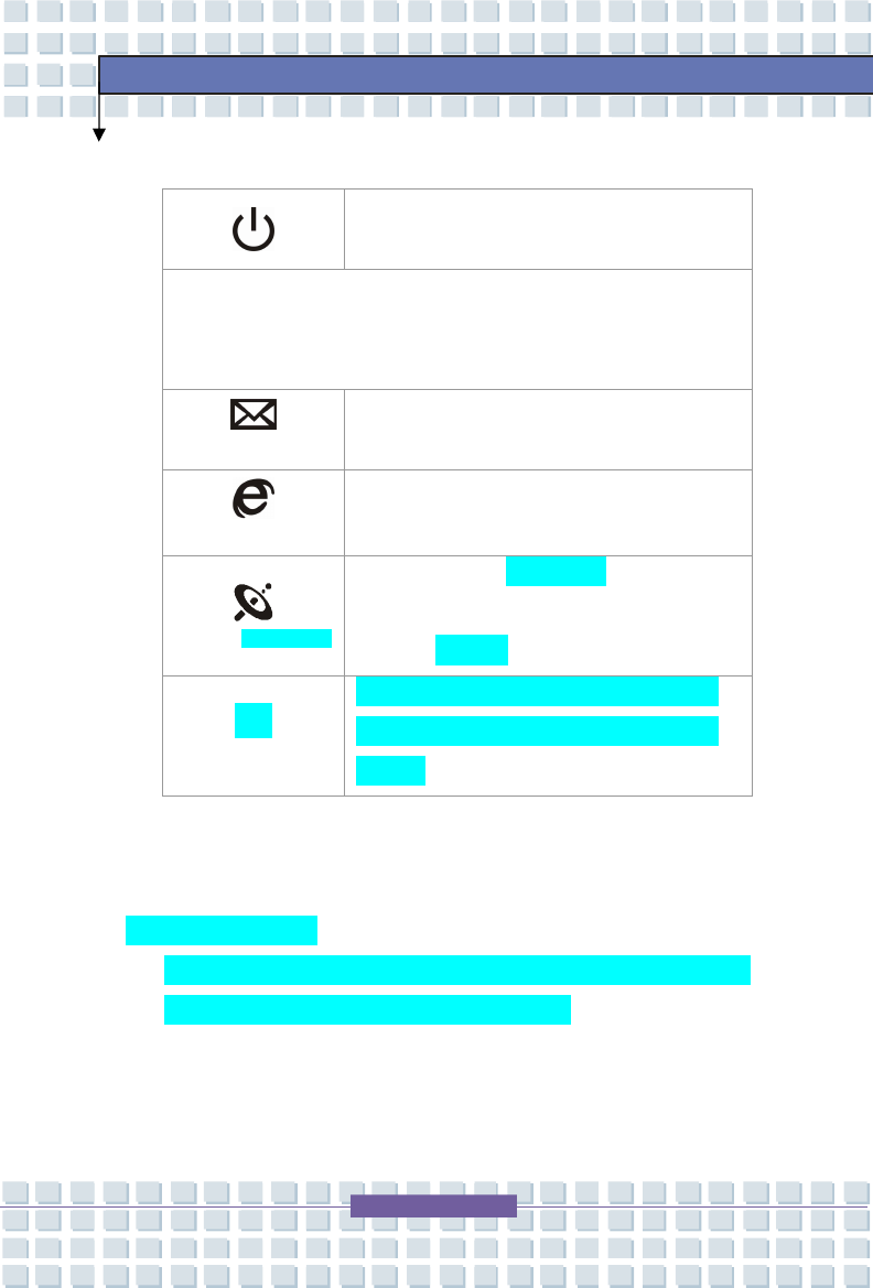
6. Quick Launch Buttons and Power Button
Power Button: To turn your Notebook power
ON and OFF.
Quick Launch Buttons: Simply click the quick launch buttons to
speed up the starting of the programs in common use. It helps you to
do works more efficiently.
E-mail
Press the E-mail Quick Launch Button to
launch the E-mail application.
Internet
Press the Internet Quick Launch Button to
activate the Internet browser.
WLAN & BT(optional)
Press the WLAN & BT (optional) Quick Launch
Button to enable/disable the Wireless LAN or
Bluetooth (optional) function.
P1
Press P1 Quick Launch Button to activate the
power saving function that can run SCM
program.
7. Stereo Speakers
Make high quality sound blaster with stereo system and Hi-Fi function
supported.
8. Camera (Optional)
This built-in Camera can be used for picture taking, video recoding or
conferencing, and any other interactive applications.
2-9
Getting Started
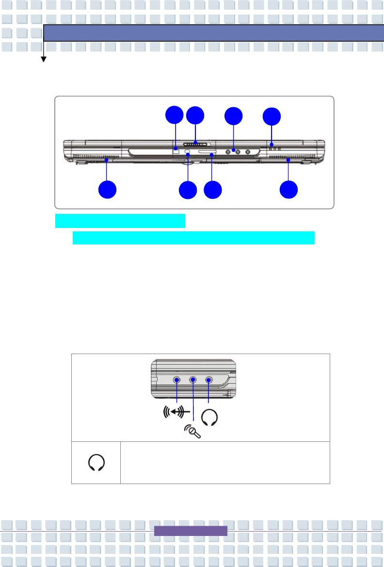
Front View
1. Consumer Infrared 規格中沒有
It is used to transfer the Remote Controller signal to control the device.
2. Cover Latch (External View)
Press Cover Latch rightward and lift the cover. The Cover Latch will
bounce back when loosing it.
3. Audio Port Connectors
Make high quality sound blaster with stereo system and Hi-Fi function
supported.
Headphone out/SPDIF out : Used for speakers or
headphones.
2
1
3
4
5
6
7
7
2-10
Getting Started
Connect the Front Right and Left speakers here.
Line In: Used for an external audio device.
Connect the Surround Right and Left speakers here.
Microphone: Used for an external microphone.
Connect the Center and Subwoofer speakers here
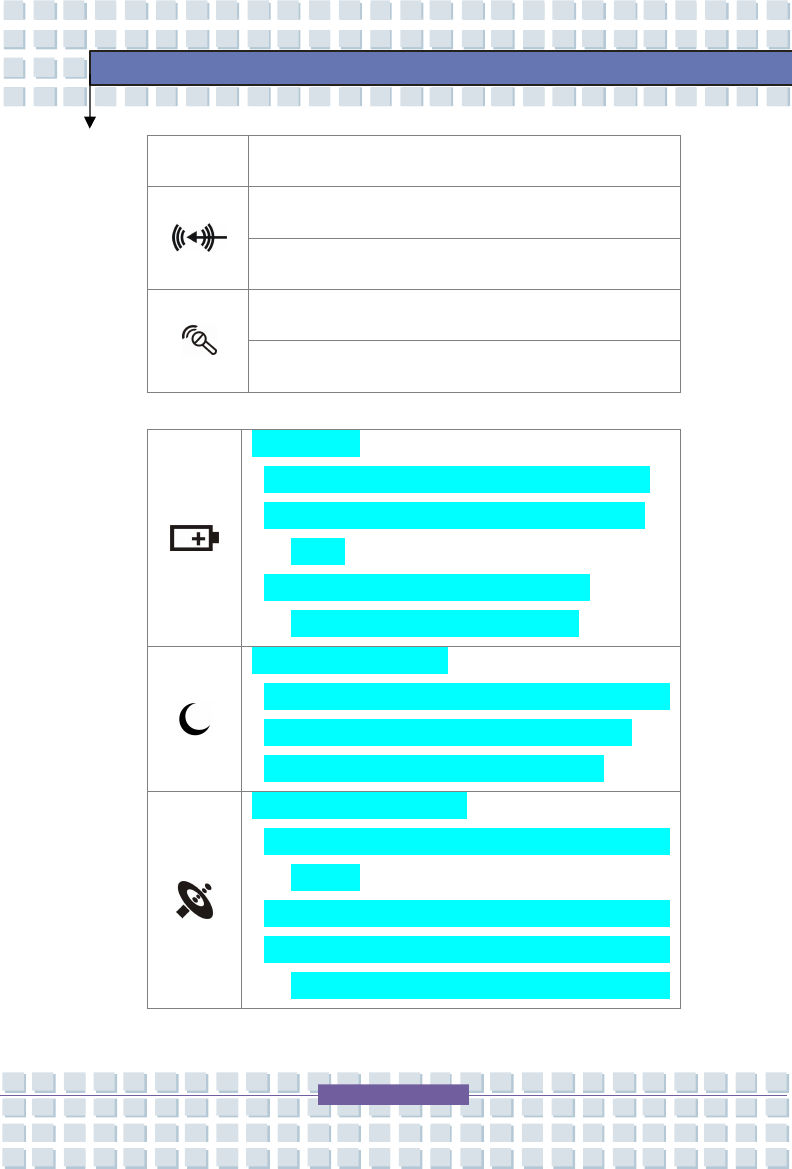
4. Status LED
Battery Status
w Glowing green when the battery is being charged.
w Glowing orange when the battery is in low battery
status.
w Blinking orange if the battery fails and it is
recommended to replace a new battery.
Power On / OFF / Standby
w Blinking orange when the system is in suspend mode.
w Glowing orange when the system is activated.
w LED goes out when the system is turned off.
Wireless LAN and Bluetooth
w Glowing green when wireless LAN function is
enabled.
w Glowing blue when Bluetooth function of is enabled.
w Glowing green and blue at the same time when
Wireless LAN and Bluetooth function are both
2-11
Getting Started
enabled.
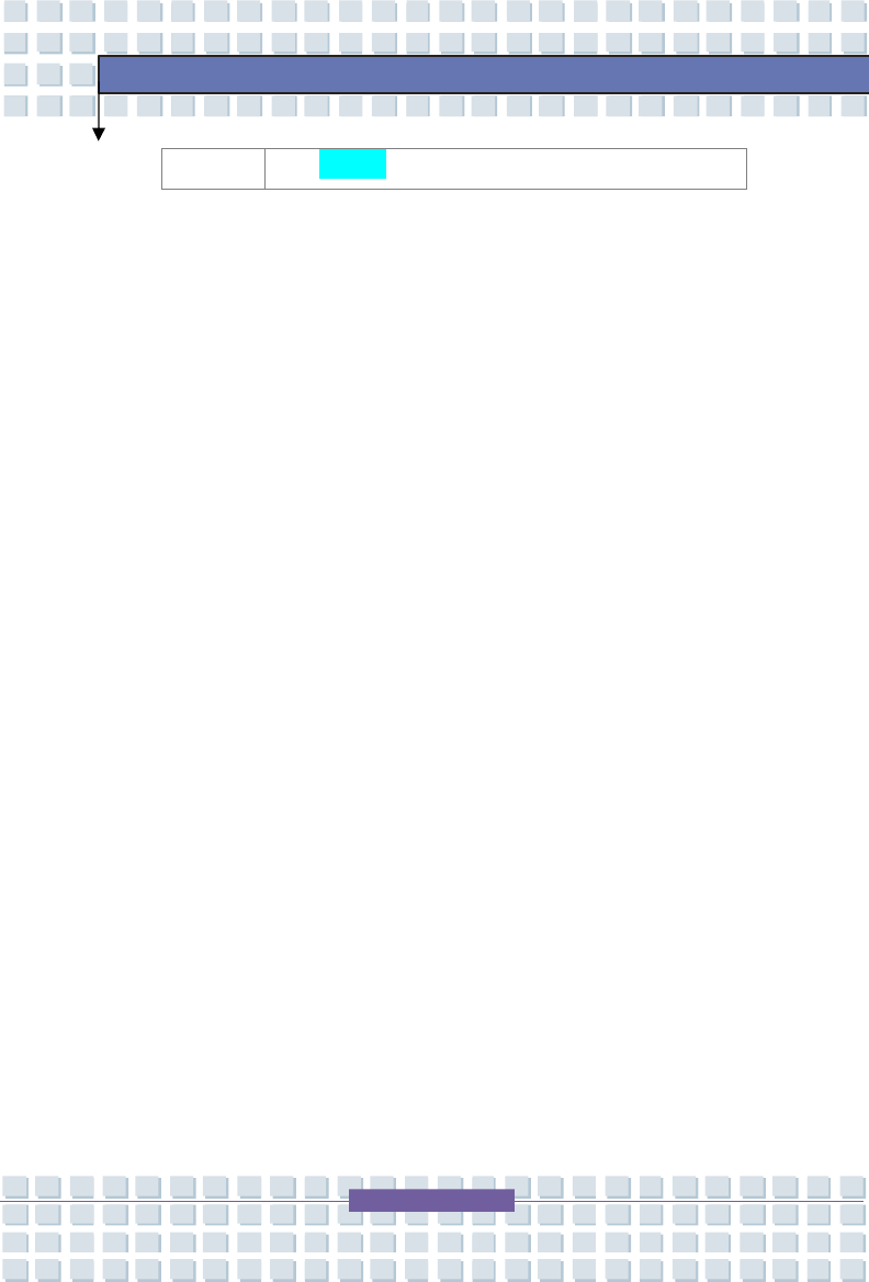
5. IEEE 1394
The IEEE 1394 port is a high-speed bus that allows you to connect
high-end digital devices such as the DV (digital video camera).
6. 3 in 1 Card Reader
The built-in card reader supports MMC (multi-media card), SD (secure
digital), and MS (memory stick) cards.
7. Stereo Speakers
Make high quality sound blaster with stereo system and Hi-Fi function
supported.
2-12
Getting Started
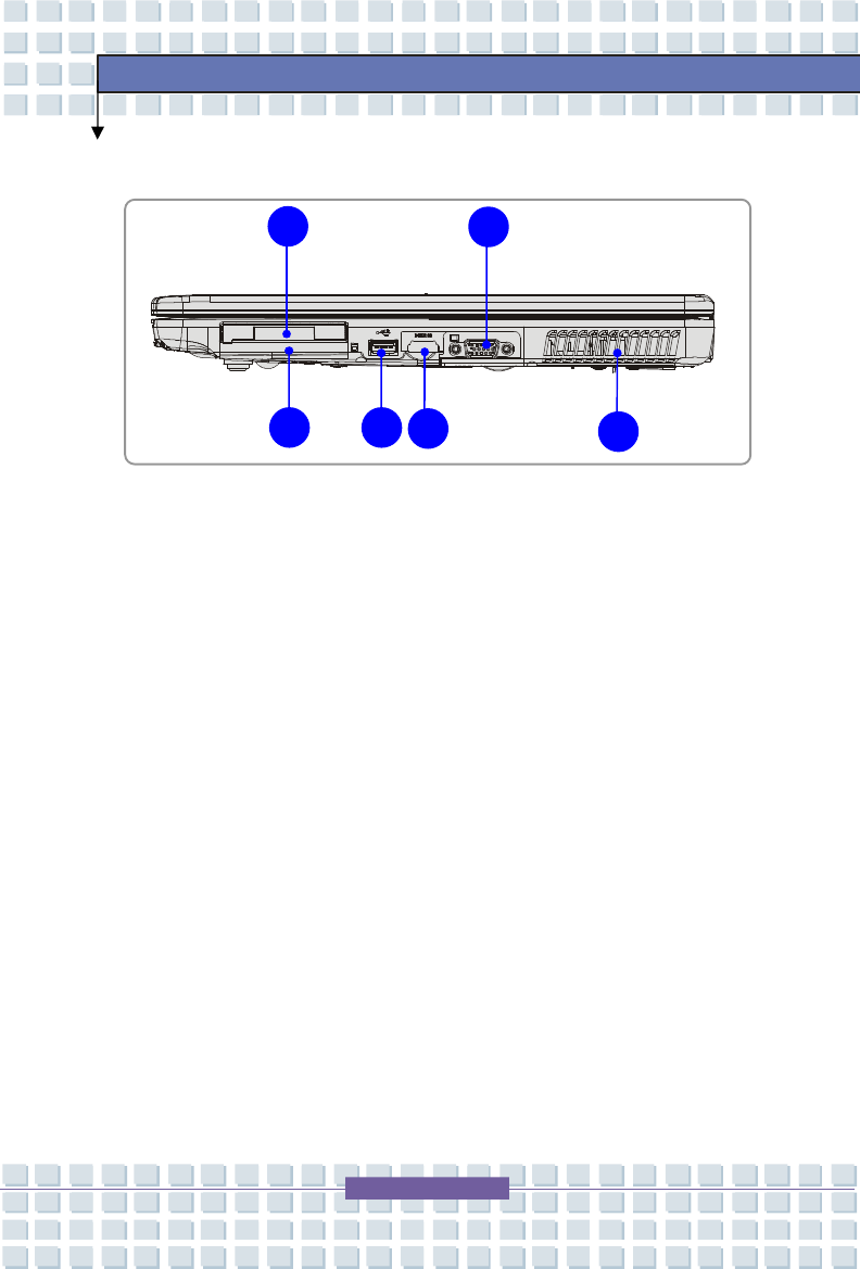
Right-side View
1. Express Card Slot
The computer provides an Express Card slot. The new Express
Card interface is smaller and faster than PC Card interface. The
Express Card technology takes advantage of the scalable,
high-bandwidth serial PCI Express and USB 2.0 interfaces.
2. PC Card Slot
The computer provides a PC card slot to support one Type-II PC card for
expansion functions, such as LAN/WLAN card, modem card, memory card,
etc.
3. USB Port
The USB 2.0 port allows you to connect USB-interface peripheral devices,
such as the mouse, keyboard, modem, portable hard disk module, printer
and more.
4. HDMI Connector
HDMI (High-Definition Multimedia Interface) is an all-digital audio/video
interface, it supports any TV or PC video format.
2
1
3
4
5
6

2-13
Getting Started
5. Ventilator
The ventilator is designed to cool the system. DO NOT block the ventilator
for air circulation.
6. VGA Port
The 15-pin-D-sub VGA port allows you to connect an external monitor or
other standard VGA-compatible device (such as a projector) for a great
view of the Notebook display.
2-14
Getting Started
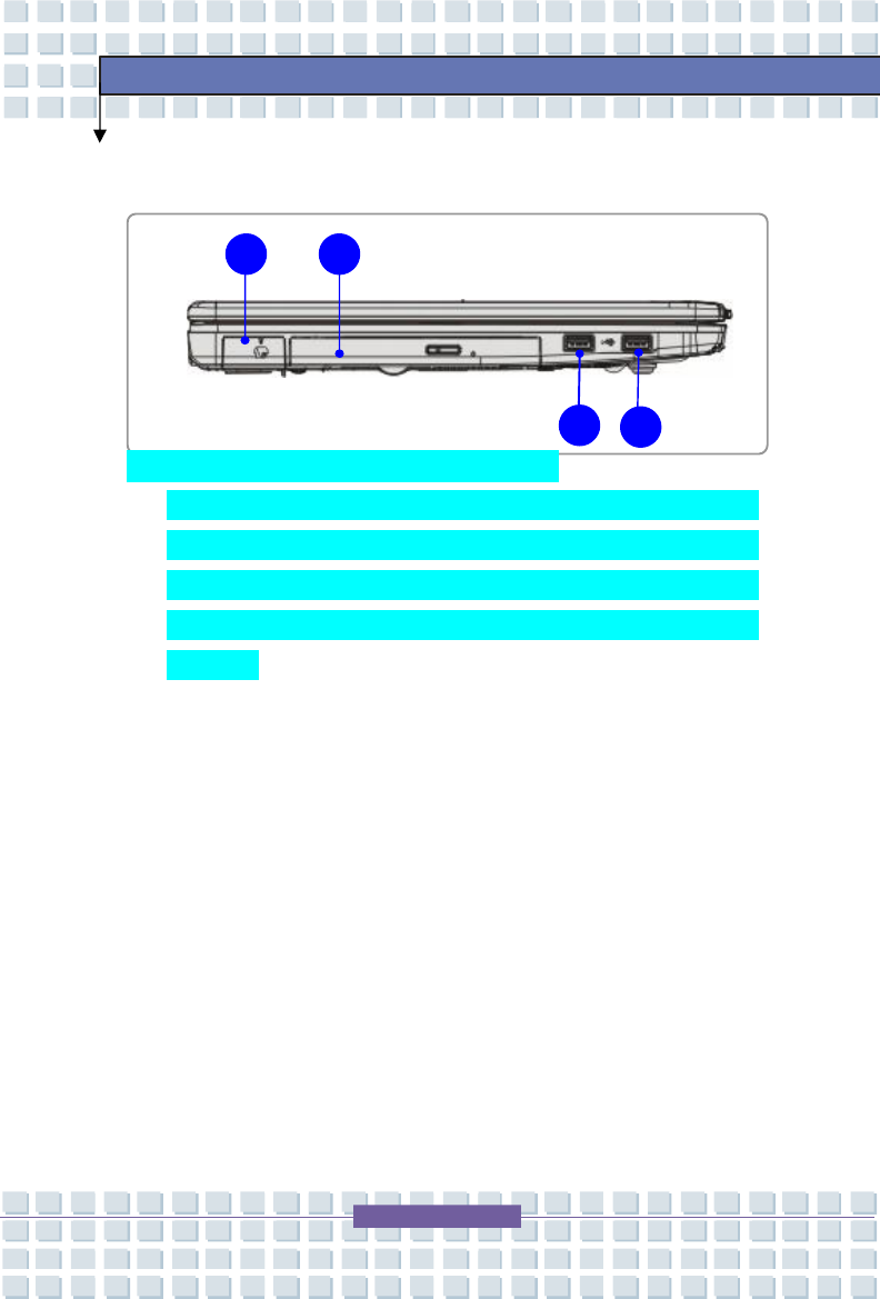
Left-side View
1. TV-Tuner Connector (Optional) 規格中沒有提到
This notebook provides you with a high quality TV viewing experience via
the TV-Tuner Connector. This connector may be a Digital TV-tuner
connector; or Analog TV-tuner connector; or Hybrid TV-tuner connector,
depending on the model you purchase. Check the local dealer for detailed
information.
2. Optical Device Drive
The optical device allows you to use the CD/DVD disc for installing software,
accessing data and playing music/movie on the computer. Lightscribe
function allows users to have brief texts curved on the disks.
3. USB Port
The USB 2.0 port allows you to connect USB-interface peripheral devices,
such as the mouse, keyboard, modem, portable hard disk module, printer
and more.
2
1
3
3
2-15
Getting Started
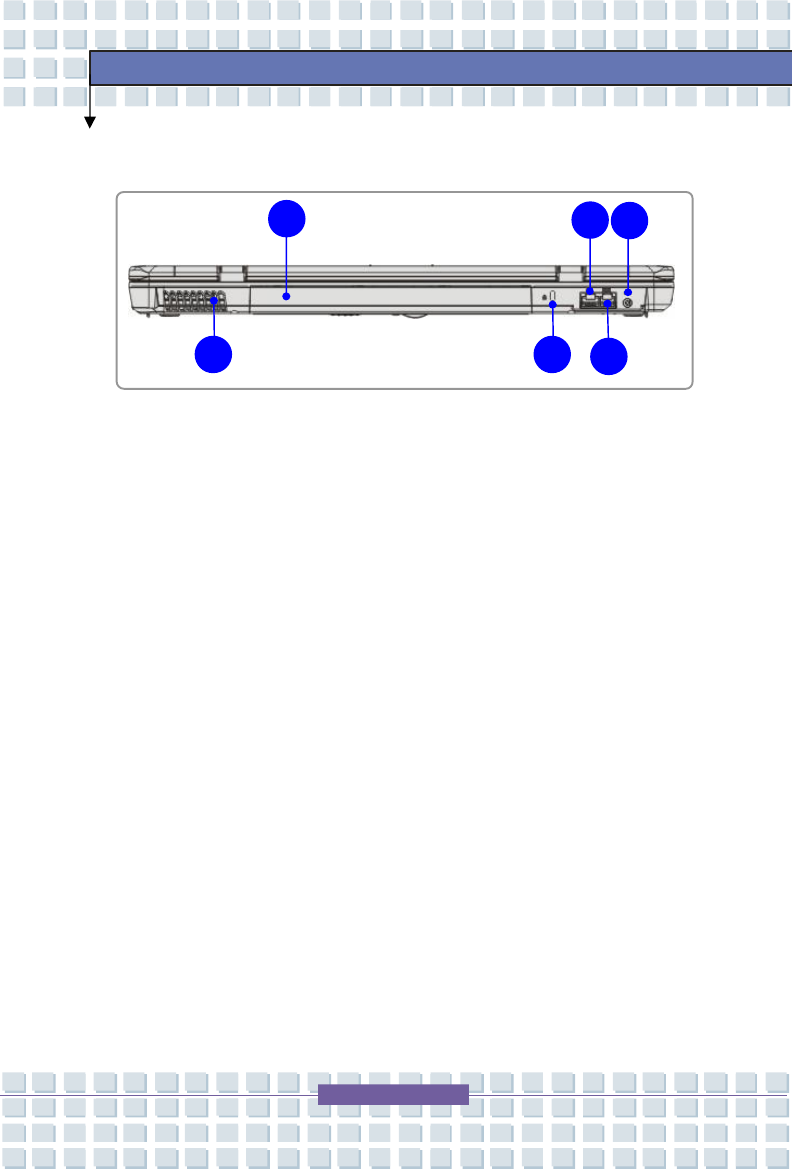
Rear View
1. Battery Pack (Rear View)
This notebook will be powered by the battery pack when the AC adapter is
disconnected.
2. RJ-45 Connector
The 10/100 Ethernet connector is used to connect a LAN cable for network
connection.
3. Power Connector
To connect the AC adapter and supply power for the notebook.
4. Ventilator
The ventilator is designed to cool the system. DO NOT block the ventilator
for air circulation.
5. Kensington Lock
This port is used to lock the computer to location for security.
6. RJ-11 Connector
The computer provides a built-in modem that allows you to connect an
FJ-11 telephone line through this connector. With the 56K V.90 modem,
you can make a dial-up connection.
2
1
3
4
5
6
2-16
Getting Started
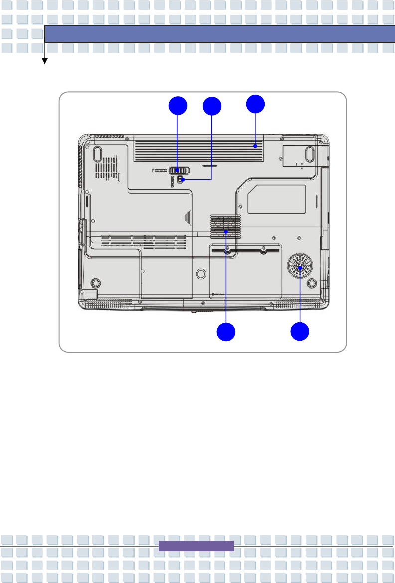
Bottom View
1. Battery Release Button
It is a bounce-back device as a preparation for releasing the battery pack.
Press it with one hand and pull the battery pack carefully with the other.
2. Battery Lock/Unlock Button
Battery cannot be moved when the button is positioned on lock status.
Once the button is pushed to unlock position, the battery is removable.
2
1
3
4
5

2-17
Getting Started
3. Battery Pack
This notebook will be powered by the battery pack when the AC adapter is
disconnected.
4. Stereo Speaker
Make high quality sound blaster with stereo system and Hi-Fi function
supported.
5. Ventilator
The ventilator is designed to cool the system. DO NOT block the ventilator
for air circulation.
2-18
Getting Started
w
v
w
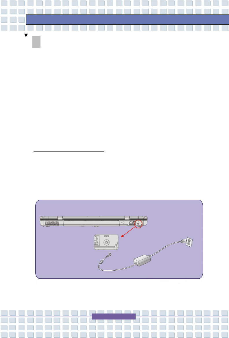
Power Management
AC Adapter
Please be noted that it is strongly recommended to connect the AC adapter and
use the AC power while using this notebook for the first time. When the AC
adapter is connected, the battery is being charged immediately.
NOTE that the AC adapter included in the package is approved for your
notebook; using other adapter model may damage the notebook or other
devices on the notebook.
Connecting the AC Power
1. Unpack the package to find the AC adapter and power cord.
2. Attach the power cord to the connector of the AC adapter.
3. Plug the DC end of the adapter to the notebook, and the male end
of the power cord to the electrical outlet.
2-19
Getting Started
Disconnecting the AC Power
When you disconnect the AC adapter, you should:
1. Unplug the power cord from the electrical outlet first.
2. Unplug the connector from the notebook.
3. Disconnect the power cord and the connector of AC adapter.
4. When unplugging the power cord, always hold the connector part of the
cord. Never pull the cord directly!
2-20
Getting Started
Battery Pack
This notebook is equipped with a high-capacity 6-cell or 9-cell Li-ion Battery pack.
The rechargeable Li-ion battery pack is an internal power source of the
notebook.
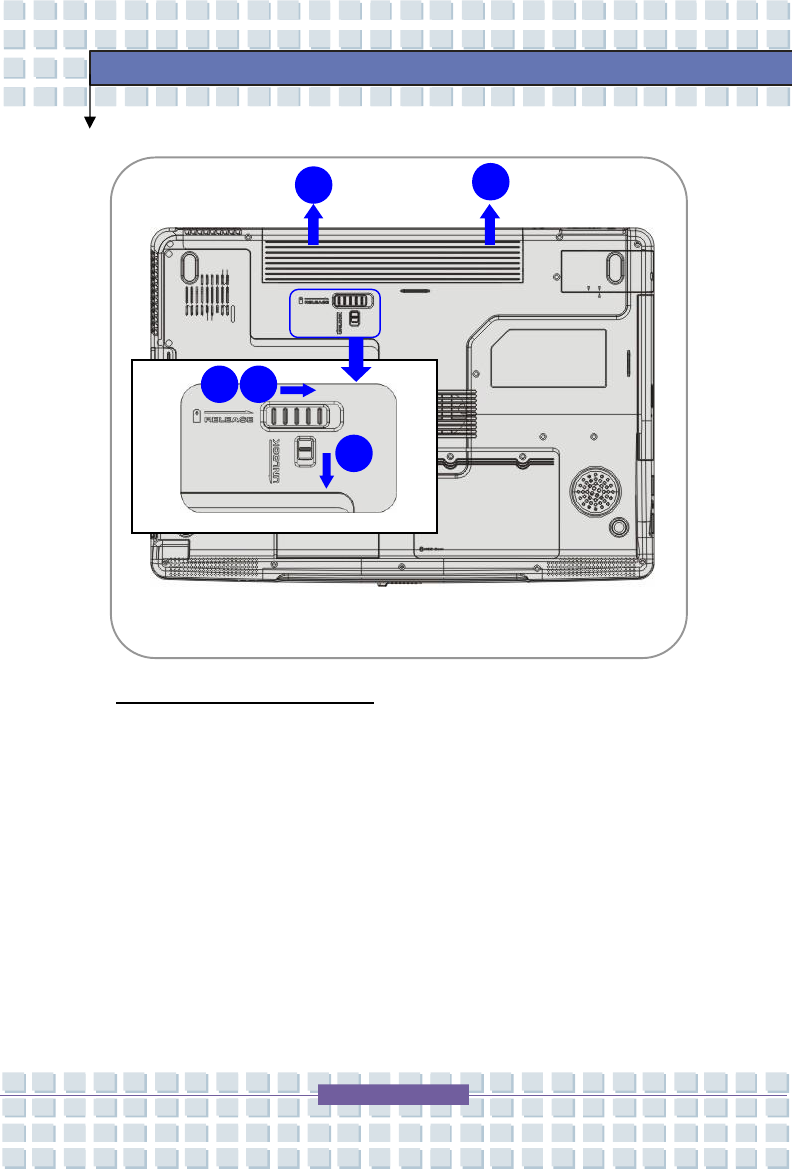
Releasing the Battery Pack
It is recommended to have an extra battery in reserve to avoid this notebook
from lacking of power supply. Please contact your local dealer for standard
battery pack.
To remove the battery pack:
1. Make sure the Notebook is turned off.
2. Check the Lock/Unlock button is in unlocked status.
3. Locate the Battery Release Button on the bottom side.
4. Push the Release Button to the direction of arrow showing below the
button.
5. Slide the left side of the battery pack first out of the compartment and
then pull the right side of the battery pack.
2-21
Getting Started
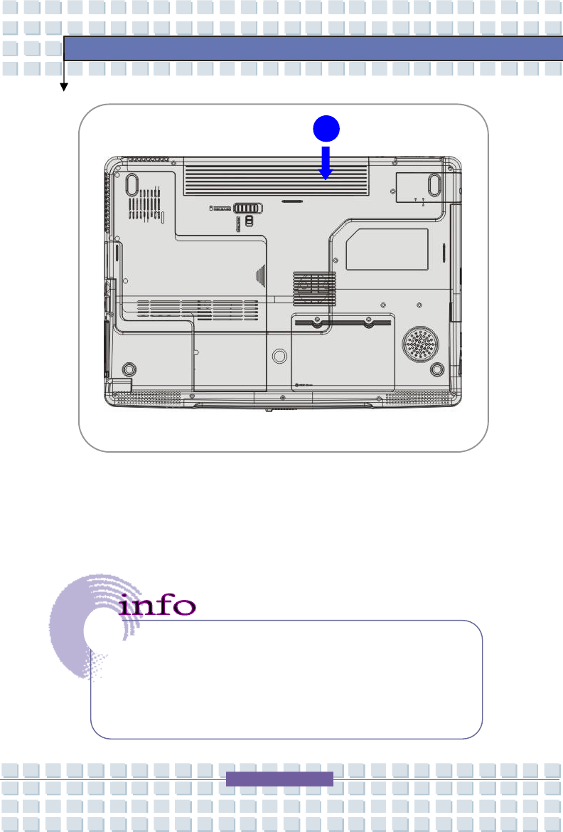
Replacing the Battery Pack
1. Insert the right side of battery pack into the compartment.
2. Slightly slide and press the battery pack into the right place.
3. After the right side of the battery pack fitting the right track, then
slightly press the left side of battery pack into the battery chamber.
4. Make sure the Lock/Unlock Button is in lock position.
2
3
4
5
5
2-22
Getting Started
Warning
1. Do not try to disassemble THE BATTERY PACK.
2. Please follow your local laws and regulations to recycle the
unused
battery pack.
1
2-23
Getting Started
Using the Battery Pack
Battery Safety Tips
Replacing or handling the battery incorrectly may present a risk of fire or
explosion, which could cause serious injury.
w Only replace the main battery pack with the same or equivalent type of
battery.
w Do not disassemble, short-circuit or incinerate batteries or store them to
temperatures above +60° C (+140° F).
w Do not temper with batteries. Keep them away from children.
w Do not use rusty or damaged batteries.
w Dispose of batteries according to local regulations. Check with your
local solid waste officials for details about recycling options or for proper
disposal in your area.
Conserving Battery Power
Efficient battery power is critical to maintain a normal operation. If the battery
power is not managed well, the saved data and customized settings may be lost.
Follow these tips to help optimizing battery life and avoid a sudden power loss.
w Suspend system operation if the system will be idle for a while or
shorten the Suspend Timer’s time period.
w Turn off the system if you won’t be using it for a period of time.
w Disable unneeded settings or remove idle peripherals to conserve
power.
w Connect an AC adapter to the system whenever possible.

2-24
Getting Started
Charging the Battery Pack
The battery pack can be recharged while it is installed in the Notebook. Please
pay attention to the following tips before recharging the battery:
w If a charged battery pack is not available, save your work and close all
running programs and shut down the system or Save-to-Disk.
w Plug in an external AC/DC power source.
w You can use the system, suspend system operation or shut down and
turn off the system without interrupting the charging process.
w The battery pack uses Lithium-ion battery cells that have no “memory
effect.” You do not need to discharge the battery pack before you
begin charging. However, to optimize the life of battery, we suggest
that consuming the battery power completely once a month is
necessary.
w If you do not use the Notebook for a long time, it is suggested to remove
the battery pack from your Notebook. This may be helpful to extend
your battery life.
w The actual charging time will be determined by the applications in use.

2-25
Getting Started
Basic Operations
If you are a beginner to the Notebook, please read the following tips to make
yourself safe and comfortable during the operations.
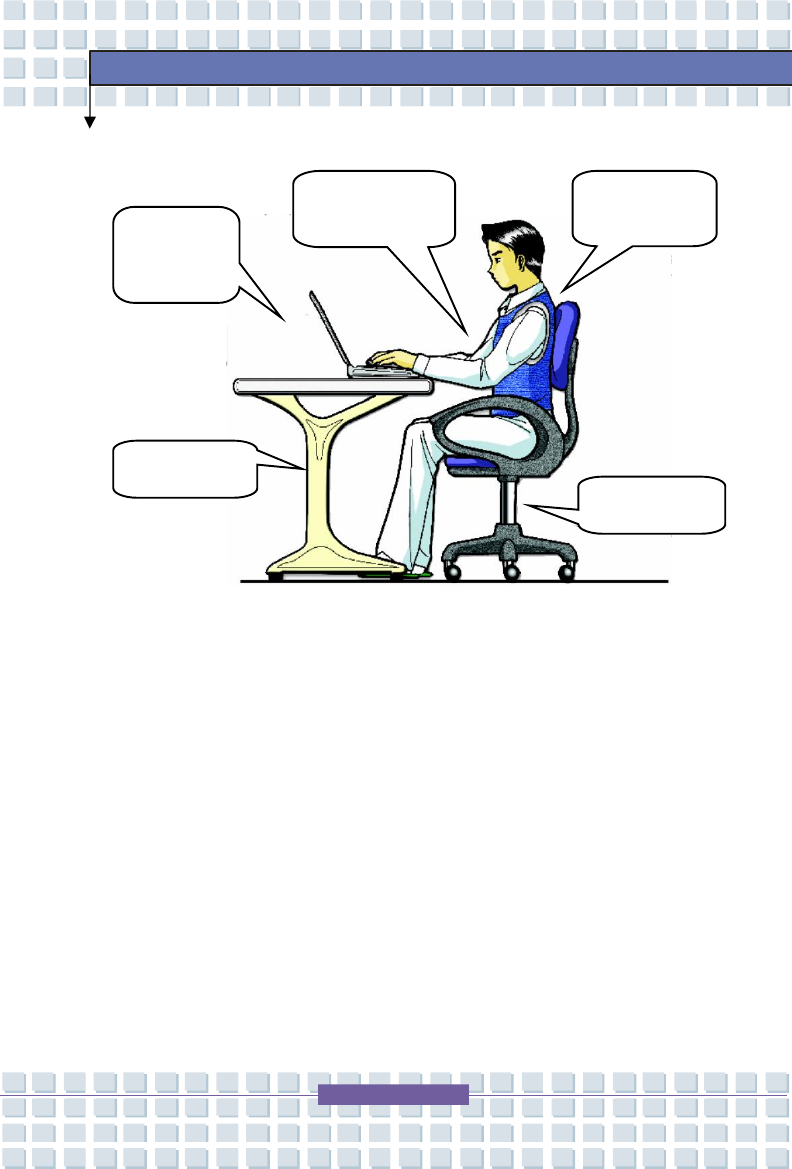
Safety and Comfort Tips
The Notebook is a portable platform that allows you to work anywhere.
However, choosing a good workspace is important if you have to work with your
Notebook for long periods of time.
w Your work area should have enough illumination.
w Choose the proper desk and chair and adjust their height to fit your
posture when operating.
w When sitting on the chair and adjust the chair’s back (if available) to
support your back comfortably.
w Place you feet flat and naturally on the floor, so that your knees and
elbows have the proper position (about 90-degree) when operating.
w Put your hands on the desk naturally to support your wrists.
w Adjust the angle/position of the LCD panel, so that you can have the
optimal view.
w Avoid using your Notebook in the space where may cause your
discomfort (such as on the bed).
w The Notebook is an electrical device, please treat it with great care to
avoid personal injury.
2-26
Getting Started
Have a Good Work Habit
Have a good work habit is important if you have to work with your Notebook for
long periods of time; otherwise, it may cause discomfort or injury to you. Please
keep the following tips in mind when operating.
w Change your posture frequently.
w Stretch and exercise you body regularly.
w Remember to take breaks after working for a period of time.
Adjust the
angle and
position of
LCD panel.
Adjust the
desk’s height.
Keep your hands
and feet with
optimal comfort.
Sit straight and
keep a good
posture
.
Adjust the
chair’s height.
2-27
Getting Started
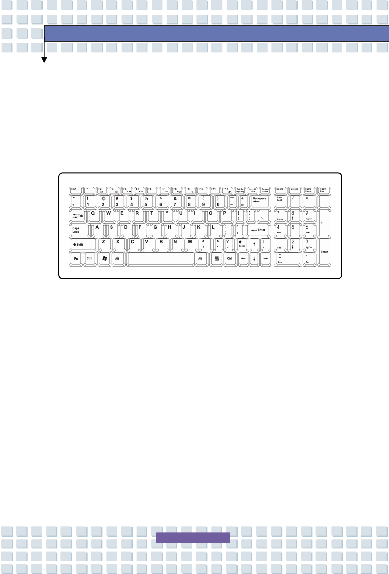
Knowing the Keyboard
The Notebook’s keyboard provides all the functions of a full-sized keyboard and
an additional [Fn] key for specific functions on the Notebook. The keyboard
can be divided into four categories: Typewriter keys, Cursor keys, Numeric
keys and Function keys.
2-28
Getting Started
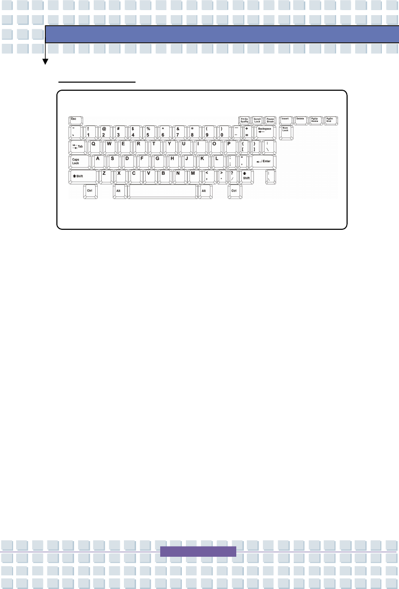
Typewriter Keys
The function of these Typewriter keys is the major function of the keyboard,
which is similar to the keys on a typewriter. It also provides several keys for
special purposes, such as the [Ctrl], [Alt] and [Esc] key.
When the lock keys are pressed, the corresponding LEDs will light up to indicate
their status:
n Num Lock: Press and hold the [Fn] key and press this key to toggle the
Num Lock on and off. When this function is activated, you can use the
numeric keys that are embedded in the typewriter keys.
n Caps Lock: Press this key to toggle the Caps Lock on and off. When this
function is activated, the letters you type are kept in uppercase.
n Scroll Lock: Press and hold the [Fn] key and press this key to toggle the
Scroll Lock on and off. This function is defined by individual programs,
and it is usually used under DOS.
2-29
Getting Started
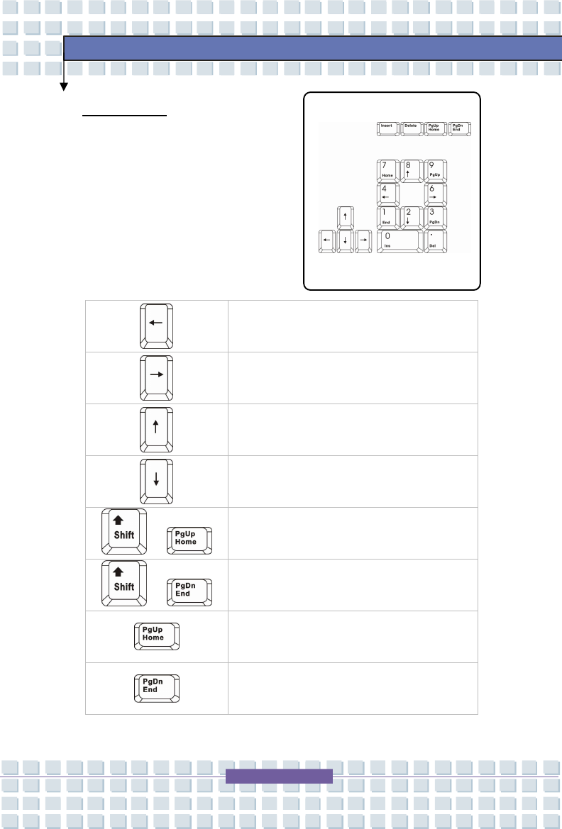
Cursor Keys
The keyboard provides four cursor
(arrow) keys and [Home], [PgUp], [PgDn],
[End] keys at the lower right corner,
which are used to control the cursor
movement.
Move the cursor left for one space.
Move the cursor right for one space.
Move the cursor up for one line.
Move the cursor down for one line.
+
Move to the previous page.
+
Move to the next page.
Move to the beginning of the line (or
document).
Move to the end of the line (or document).
2-30
Getting Started
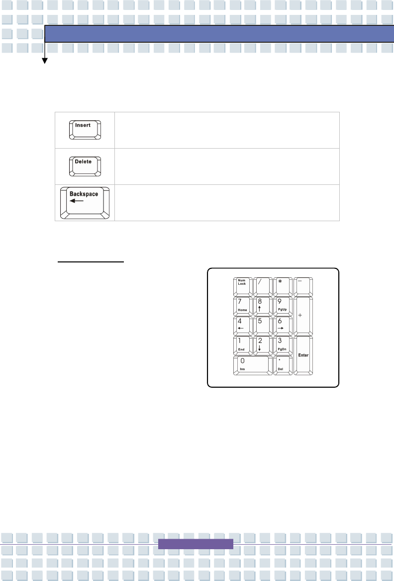
The Backspace key, [Ins] and [Del] keys at upper right corner are use for editing
purpose.
This key is used to switch the typing mode between
“insert” and “overtype” modes.
Press this key to delete one character to the right of the
cursor and move the following text left for one space.
Press this key to delete one character to the left of the
cursor and move the following text left for one space.
Numeric Keys
The keyboard provides a set of numeric
keypad, which is embedded in the
typewriter keys. When the Num Lock
is activated, you can use these numeric
keys to enter numbers and calculations.
2-31
Getting Started
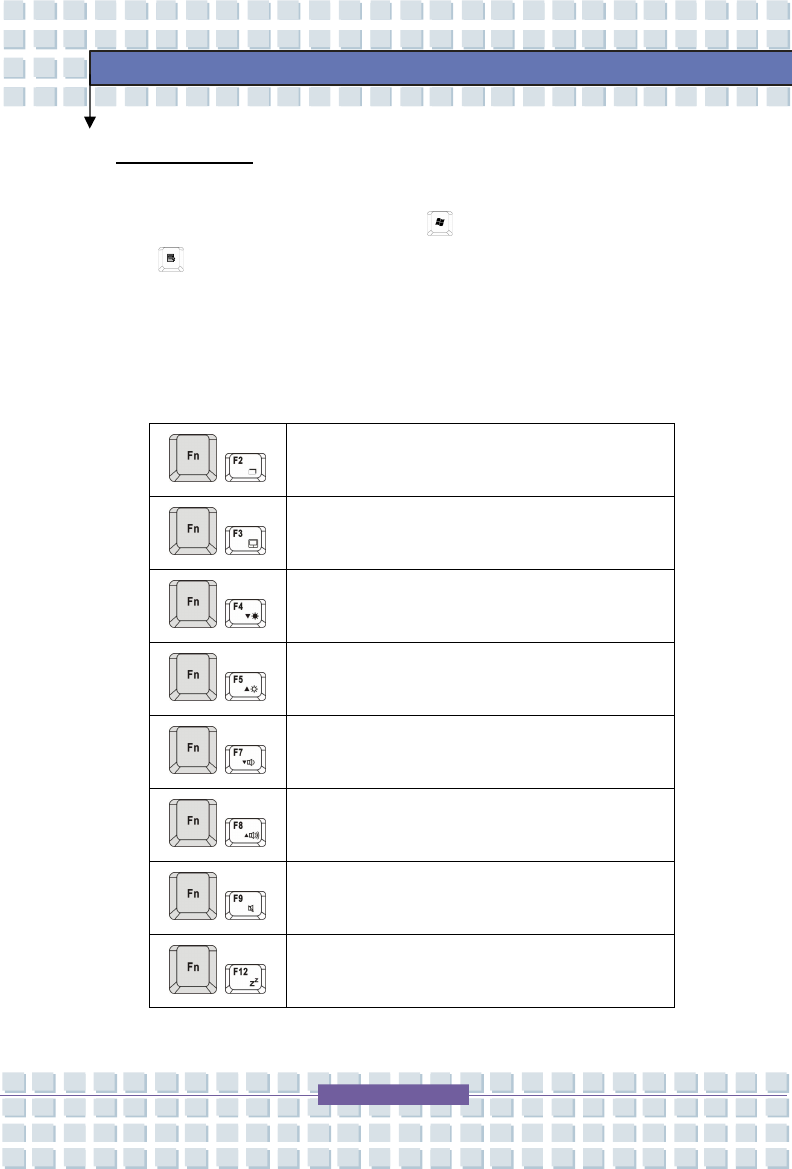
Function Keys
n Windows Keys
You can find the Windows Logo key ( ) and one Application Logo key
() on the keyboard, which are used to perform Windows-specific
functions, such as opening the Start menu and launching the shortcut
menu. For more information of the two keys, please refer to your
Windows manual or online help.
n [Fn] Key
+
Switch the display output mode between the
LCD, external monitor and Both.
+ Enable or disable the touchpad function.
+ Decrease the LCD brightness.
+ Increase the LCD brightness.
+ Decrease the built-in speaker’s volume.
+ Increase the built-in speaker’s volume.
+ Disable the computer’s audio function.
+
Force the computer into suspend mode
(depending on the system configuration).
2-32
Getting Started
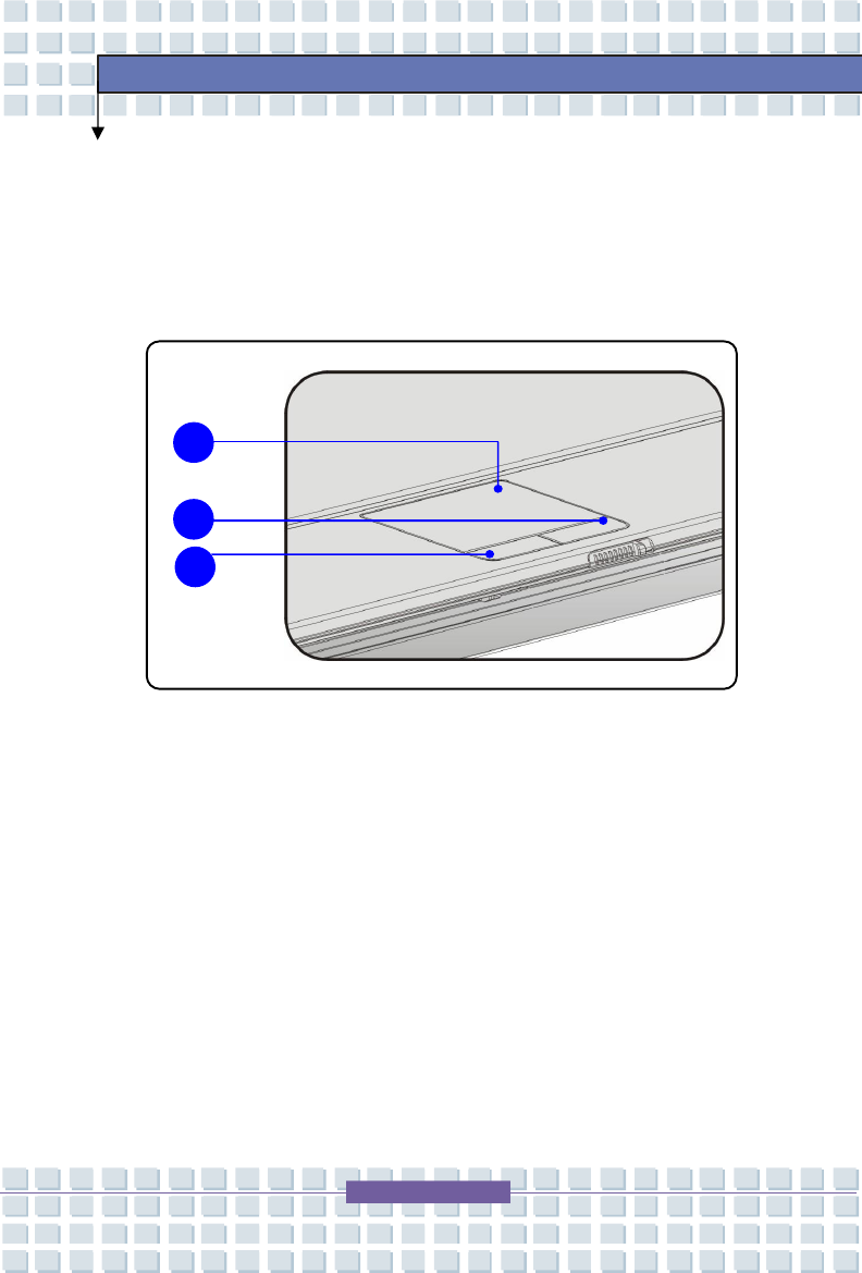
Knowing the Touchpad
The touchpad integrated in your Notebook is a pointing device that is compatible
with standard mouse, allowing you to control the Notebook by pointing the
location of the cursor on the screen and making selection with its two buttons.
1. Cursor Movement Area
This pressure-sensitive area of the touchpad, allows you to place your
finger on it and control the cursor on the screen by moving your finger.
2. Right Button
Acts as the mouse’s right button.
3. Left Button
Acts as the mouse’s left button.
2
1
3
2-33
Getting Started
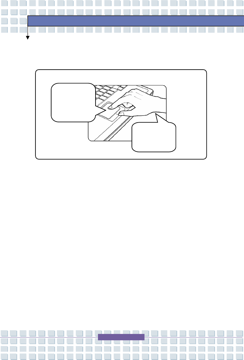
Using the Touchpad
Read the following description to learn how to use the touchpad:
n Positioning and Moving
Place your finger on the touchpad (usually using the forefinger), and the
rectangular pad will act as a miniature duplicate of your display. When
you move your fingertip across the pad, the cursor on the screen will move
simultaneously in the same direction. When your finger reaches the edge
of the pad, lift your finger and replace it on a proper location of the
touchpad.
n Point and Click
When you have moved and placed the cursor over an icon, a menu item or
a command that you want to execute, simply tap slightly on the touchpad or
press the left button to select. This procedure, called as point and click is
the basics of operating your Notebook. Unlike the traditional pointing
device such as the mouse, the whole touchpad can act as a left button, so
that your each tap on the touchpad is equivalent to pressing the left button.
Tapping twice more rapidly on the touchpad is to execute a double-click.
n Drag and Drop
You can move files or objects in your Notebook by using drag-and-drop.
To do so, place the cursor on the desired item and slightly tap twice on the
touchpad, and then keep your fingertip in contact with the touchpad on the
second tap. Now, you can drag the selected item to the desired location
by moving your finger on the touchpad, and then lift your finger from the
touchpad to drop the item into place. Alternately, you can press and hold
the left button when you select an item, and then move your finger to the
2-34
Getting Started
desired location; finally, release the left button to finish the drag-and-drop
operation.
Move the
cursor by
sliding your
fingertip.
Put your wrist
on the desk
comfortably.
Using the Touchpad
2-35
Getting Started
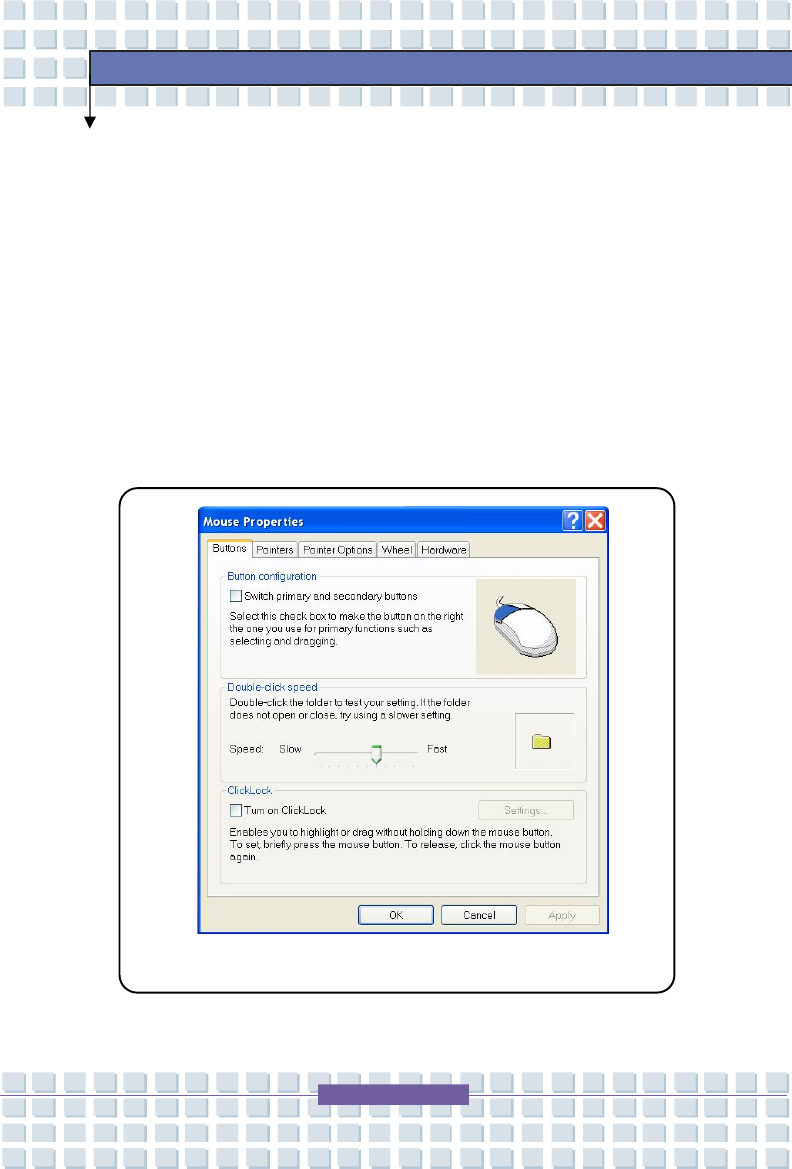
n Configuring the Touchpad
You can customize the pointing device to meet your personal needs. For
example, if you are a left-hand user, you may want to swap the functions of
the two buttons. In addition, you can change the size, shape, moving
speed and other advanced features of the cursor on the screen.
To configure the touchpad, you can use the standard Microsoft or IBM PS/2
driver in your Windows operating system. The Mouse Properties in
Control Panel allows you to change the configuration.
Mouse Properties Window
2-36
Getting Started
About Hard Disk Drive
Your Notebook is equipped with a 2.5-inch hard disk drive. The hard disk drive
is a storage device with much higher speed and larger capacity than other
storage devices, such as the floppy disk drive and optical storage devices.
Therefore, it is usually used to install the operating system and software
applications.
1. To avoid unexpected data loss in your system, please backup
your critical files regularly.
2. Do not turn off the Notebook when the Hard Disk In-use LED
is on.
3. Do not remove or install the hard disk drive when the
Notebook is turned on. The replacement of hard disk drive
should be done by an authorized retailer or service
representative.
2-37
Getting Started
Using the Optical Device
Your Notebook is equipped with an optical storage device. The actual device
installed in your Notebook depends on the model you purchased.
n Super Multi Drive: A multi format recorder, allows you to record
the –R/RW, +R/RW, -RAM, CDR and CD-RW formats.
n Lightscribe: Allows users to have brief texts curved on the obverse side of
the disks with the laser read/write head of the Optical Device Drive.
1. The optical storage devices are classified as a Class 1 Laser
products. Use of controls or adjustments or performance of
procedures other than those specified here in may result in
hazardous radiation exposure.
2. Do not touch the lens inside the drive.
2-38
Getting Started
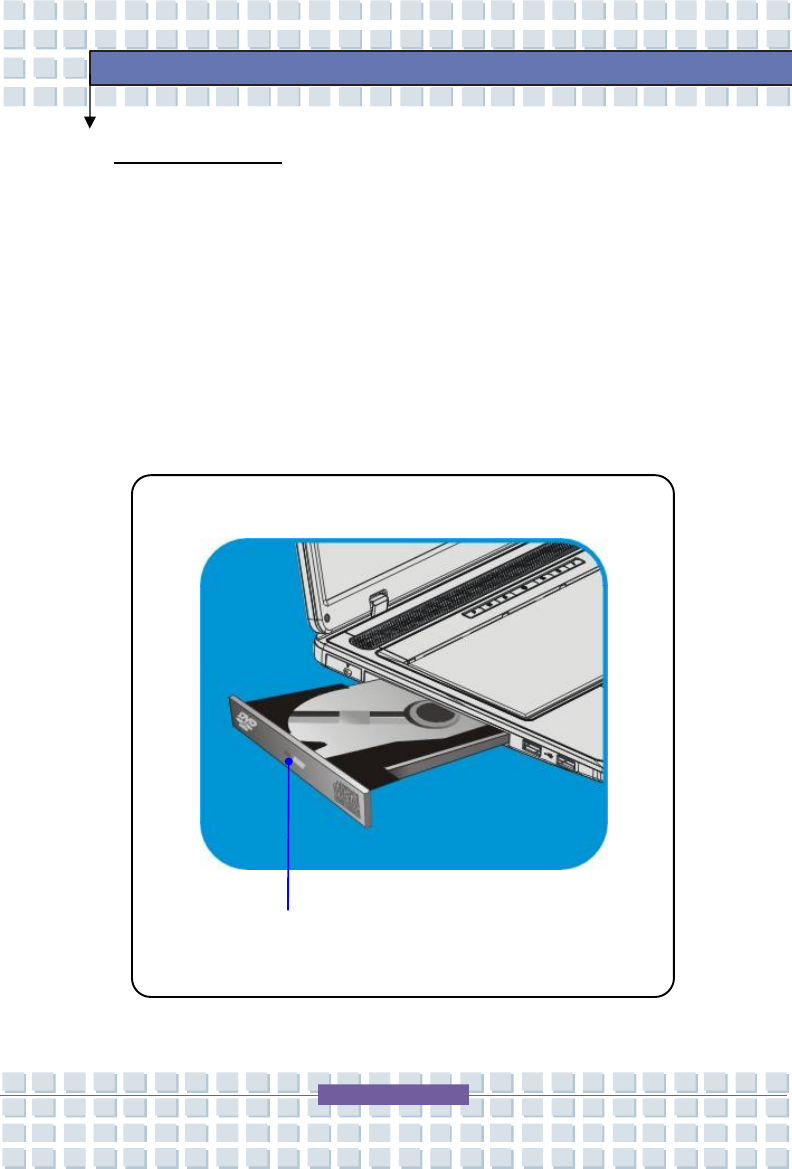
Inserting the Disk
The following instruction describes the general procedure when operating the
optical storage device.
1. Confirm that the Notebook is turned on.
2. Press the Eject Button on the drive’s panel and the disk tray will slide out
partially. Then, gently pull the tray out until fully extended.
3. Place your disk in the tray with its label facing up. Slightly press the
center of the disk to secure it into place.
4. Push the tray back into the drive.
Eject Button
2-39
Getting Started
Removing the Disk
1. Press the Eject Button on the drive’s panel and the disk tray will slide out
partially. Then, gently pull the tray out until fully extended.
2. Hold the disk by its edge with your fingers and lift it up from the tray.
3. Push the tray back into the drive.
1. Confirm that the disk is placed correctly and securely in the
tray before closing the tray.
2. Do not leave the disk tray open.

General Introductions Chapter 1
Getting Started
Chapter 2
Customizing this Notebook
Chapter 3
BIOS Einstellung
Chapter 4
Preface
3
-
2
Customizing this Notebook
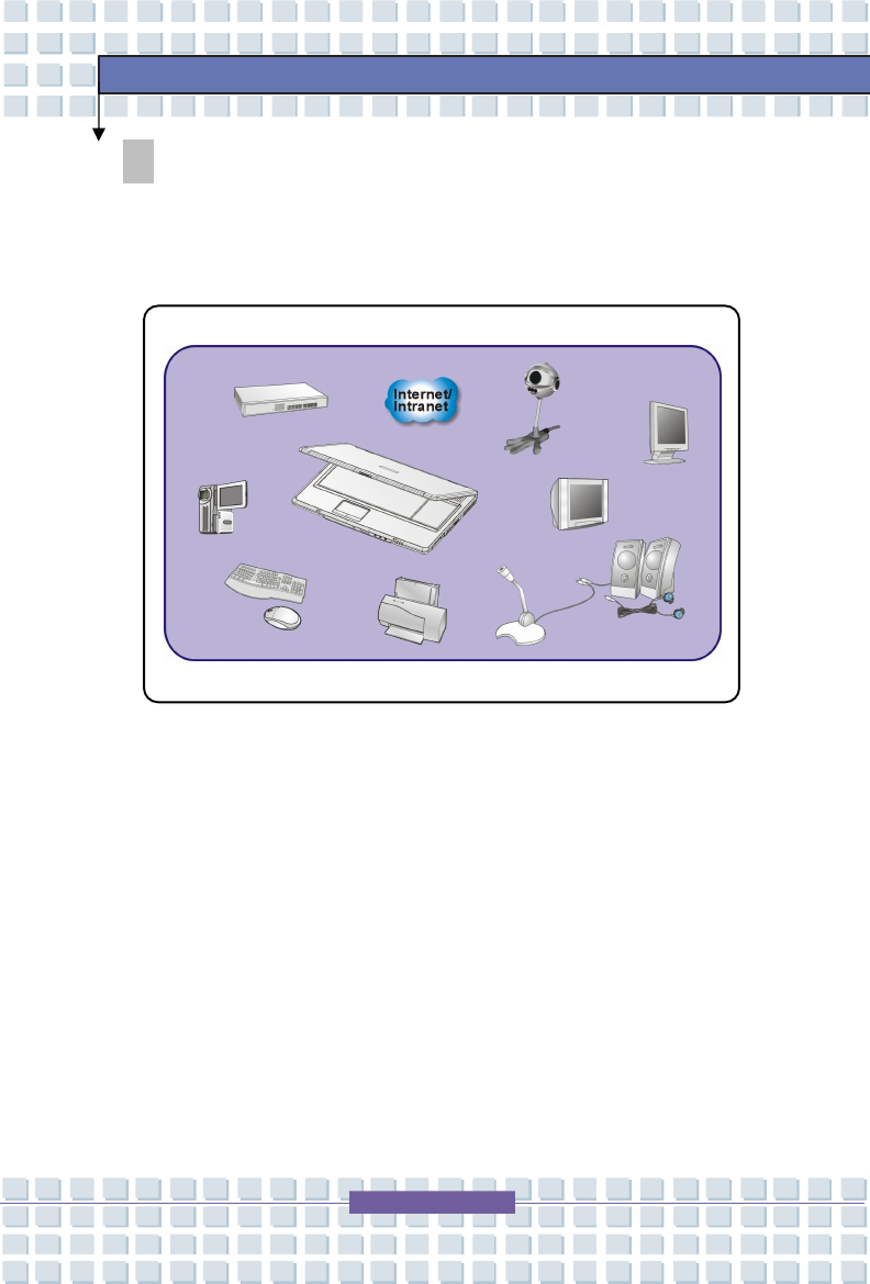
Connecting the External Devices
The I/O (input/output) ports on the Notebook allow you to connect peripheral
devices.
Mouse/ Keyboard
Printer
IEEE 1394 Device
Monitor
Television
Microphone
Speakers/
Earphones
Modem
LAN
Web Cam
3
-
3
Customizing this Notebook
Connecting the Peripheral Devices
Connecting the Mouse
You can connect a mouse to your Notebook through the USB port. To connect
the mouse:
1. Turn on the Notebook and install the mouse driver.
2. Connect your mouse to the Notebook.
3. The Notebook may auto detect your mouse driver and enable the mouse
function. If there is no detection of you mouse you can manually enable
the mouse by going to Start Menu à Control Panel à Add Hardware to
add the new device.
Connecting the Keyboard
You can connect a keyboard to your Notebook through the USB port. To
connect the keyboard:
1. Turn on the Notebook and install the keyboard driver.
2. Connect your keyboard to the Notebook.
3. The Notebook may auto detect your keyboard driver and enable the
keyboard function. If there is no detection of you keyboard you can
manually enable the keyboard by going to Start Menu à Control Panel à
Add Hardware to add the new device.
3
-
4
Customizing this Notebook
Connecting the WebCam
You can connect a WebCam to your Notebook through the USB port to connect
the WebCam:
1. Turn on the Notebook and install the WebCam driver.
2. Connect your WebCam to the Notebook.
3. The Notebook may auto detect your WebCam driver and enable the
WebCam function. If there is no detection of you WebCam you can
manually enable the WebCam by going to Start Menu à Control Panel à
Add Hardware to add the new device.
Connecting the Printer
If your printer has a USB interface, you can then use the USB port on the
Notebook to connect the printer. The following instruction describes the
general procedure to connect a printer:
1. Turn off the Notebook.
2. Connect one end of the printer cable to the Notebook’s USB port and the
other end to the printer.
3. Connect the power cord and turn on the printer.
4. Turn on the Notebook and the system will detect a new device. Install the
required driver.
For further instructions, please refer to your printer’s manual.
3
-
5
Customizing this Notebook
Connecting the External Monitor or TV
You can connect an external monitor to your Notebook through the port for a
larger view with higher resolution. To connect the monitor:
1. Make sure that the Notebook is turned off.
2. Plug the monitor’s D-type connector into the Notebook’s VGA port.
3. Connect the monitor’s power cord and turn on the monitor.
4. Turn on the Notebook and the monitor should respond by default. If not,
you can switch the display mode by pressing [Fn]+[F2]. Alternately, you
can change the display mode by configuring the settings in Display
Properties of Windows operating system.
Connecting the IEEE 1394 devices
The IEEE 1394 port of your Notebook is a next-generation serial bus that
features a high-speed transfer rate and the connection of up to 63 devices,
allowing you to connect many high-end peripheral devices and consumer
electronic appliances, such as the DV (digital video camera). The IEEE 1394
standard interface supports “plug-and-play” technology, so that you can
connect and remove the IEEE 1394 devices without turning off the Notebook.
To connect the IEEE 1394 device, simply connect the cable of the device to the
IEEE 1394 port of your Notebook.
3
-
6
Customizing this Notebook
Connecting the Communication Devices
Using the LAN
The RJ-45 connector of the Notebook allows you to connect the LAN (local area
network) devices, such as a hub, switch and gateway, to build a network
connection.
For more instructions or detailed steps on connecting to the LAN, please ask
your MIS staff or network manager for help.
Using the Modem
The built-in 56Kbps fax/data modem allows you to use a telephone line to
communicate with others or to dial-up to connect the Internet.
For more instructions or detailed steps on dialing-up through the modem, please
consult your MIS staff or Internet service provider (ISP) for help.
1. To reduce the risk of fire, use only No. 26 AWG or larger
telecommunication lone cord.
2. You are strongly recommended to install the modem driver
included in the software CD of your Notebook to take full
advantage of the modem feature.

3
-
7
Customizing this Notebook
PC Card Installation
The PC card slot of your Notebook allows you to install comprehensive Type-II
PC cards that support various functions for your necessary, including the
LAN/WLAN card, modem card and memory card.
The following instruction provides you with a basic installation for the PC card,
including how to install and remove it. For more information, please refer to the
manual of your PC card.
Installing the PC card
1. Locate the PC card slot on your notebook Notebook. If there is the
dummy card in the slot, remove it first.
2. Insert the PC card into the slot (usually with its label facing up) and push it
until it is firmly seated.
Removing the PC card
1. Press the Eject Button to make it stretch out.
2. Push the Eject Button and the PC card will slide out. Pull it out of the slot.
3
-
8
Customizing this Notebook
1. Do not hold the “golden finger” when installing the PC card;
otherwise, it may cause interference or damage to the PC
card.
2. Before removing the PC card, you should stop the device in
Windows operating system.
3
-
9
Customizing this Notebook
Express PC Card Installation
This computer provides an Express Card slot. The new Express Card interface
is smaller and faster than PC Card interface. The Express Card technology
takes advantage of the scalable, high-bandwidth serial PCI Express and USB 2.0
interfaces.
The following instruction provides you with a basic installation for the Express
Card, including how to install and remove it. For more information, please refer
to the manual of your Express Card.
Installing the Express Card
1. Locate the Express Card slot on your notebook. If there is the dummy
card in the slot, remove it first.
2. Insert the Express Card into the slot (usually with its label facing up) and
push it until it is firmly seated.
Removing the Express Card
1. Press the edge of the Express card to make the card stretch out a bit.
2. Pull the Express card out of the slot.
3. Reattach the dummy card back to the slot.
3
-
10
Customizing this Notebook
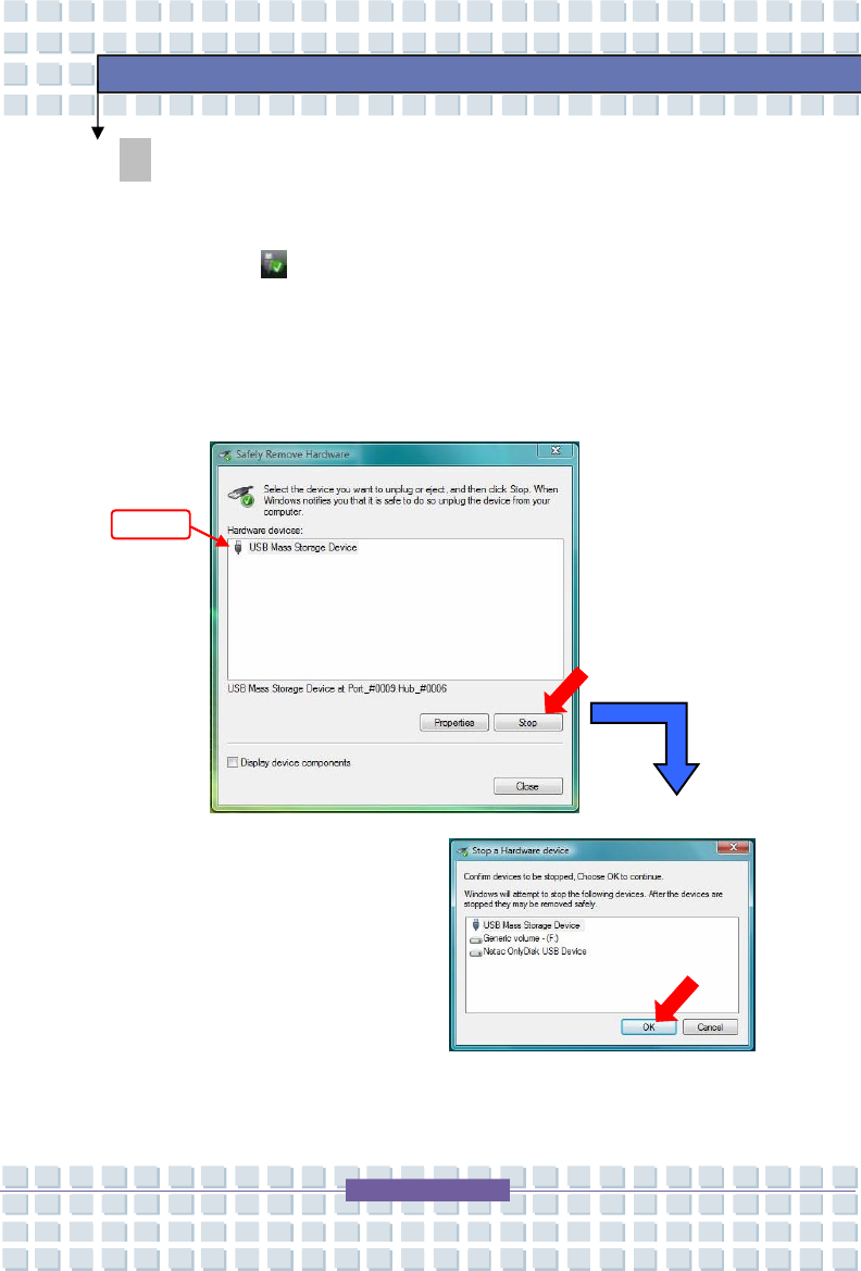
Safely Remove Hardware
If you connect any peripheral device to your system, the Safely Remove
Hardware icon will appear on the taskbar. Double-click the icon to
bring up the Safely Remove Hardware dialog box. You can see all connected
peripheral devices here. If you want to remove any of the devices, move the
cursor to the device and click Stop.
Select

General Introductions Chapter 1
Getting Started
Chapter 2
Customizing this Notebook
Chapter 3
BIOS setup
Chapter 4
Preface
4
-
2
BIOS Setup
About BIOS Setup
When to Use BIOS Setup?
You may need to run the BIOS Setup when:
w An error message appears on the screen during the system booting up
and requests you to run SETUP.
w You want to change the default settings for customized features.
w You want to reload the default BIOS settings.
How to Run BIOS Setup?
To run the BIOS Setup Utility, turn on the Notebook and press the [Del] key
during the POST procedure.
If the message disappears before you respond and you still wish to enter Setup,
restart the system by turning it OFF and ON, or simultaneously pressing
[Ctrl]+[Alt]+[Delete] keys to restart.
The screen snaps and setting options in this chapter are for your
references only. The a
ctual setting screens and options on your
Notebook may be different because of BIOS update.
4
-
3
BIOS Setup
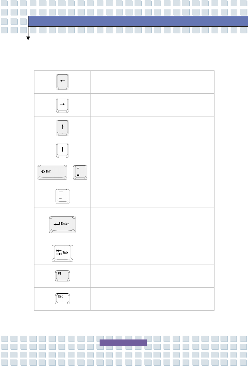
Control Keys
You can use only the keyboard to control the cursor in the BIOS Setup Utility.
Press left arrow to select one menu title.
Press right arrow to select one menu title.
Press up arrow to select one item under the menu
title.
Press down arrow to select one item under the menu
title.
+
Increase the setting value or make changes.
Decrease the setting value or make changes.
1) Open the selected item to change setting
options.
2) Bring up a sub-menu when available.
In some items, press this key to change setting field.
Bring up help screen providing the information of
control keys.
1) Exit the BIOS Setup Utility.
2) Return to the previous screen in a sub-menu.
4
-
4
BIOS Setup
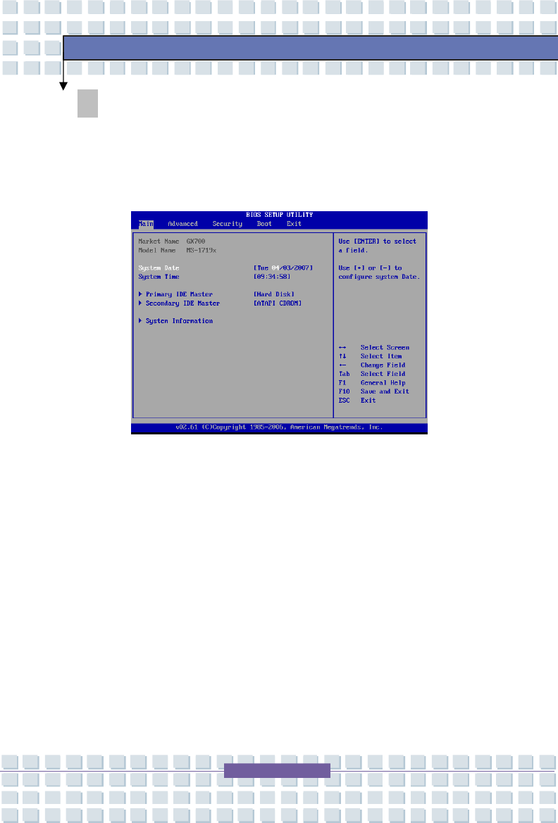
BIOS Setup Menu
Once you enter the BIOS Setup Utility, the Main menu will appear on the screen.
The Main menu displays the system information, including the basic
configuration.
Main menu
Show System Overview information about BIOS version, CPU features, Memory
size and setting of System Time and Date.
Advanced menu
Configure IDE and USB settings.
Security menu
Install or clear Supervisor’s and User’s Password settings.
Boot menu
Set up Boot Type and Boot Sequence.
Exit menu
Choose decided status before leaving the BIOS menu.
4
-
5
BIOS Setup
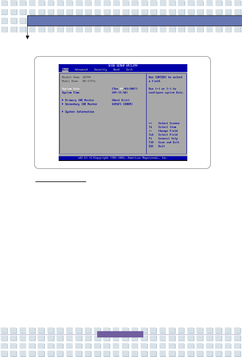
Main menu
System Overview
System Overview will show you BIOS version and other information about its
build date and update notes. Following is CPU’s information about its Type and
Speed.
System Time
This item allows you to set the system time. The system clock will go on
no matter you shut down the PC or get into sleep mode. The set format is
[hour:minute:second].

4
-
6
BIOS Setup
System Date
This item allows you to set the system date. The date format is
[day:month:date:year].
Day Day of the week, from Sun to Sat, which is determined by
BIOS (read-only).
Month
The month from 01 (January) to 12 (December).
Date The date from 01 to 31.
Year The year can be adjusted by users.
Primary/Secondary IDE Master
The item displays the types of the primary/secondary IDE Master devices
installed in the Notebook. Press [Enter] to bring up a window showing the
detailed information of the device, including the device name, vendor, LBA
mode, PIO mode and more.
System Information
This item indicates the information of firmware, processor, and system
memory.
4
-
7
BIOS Setup
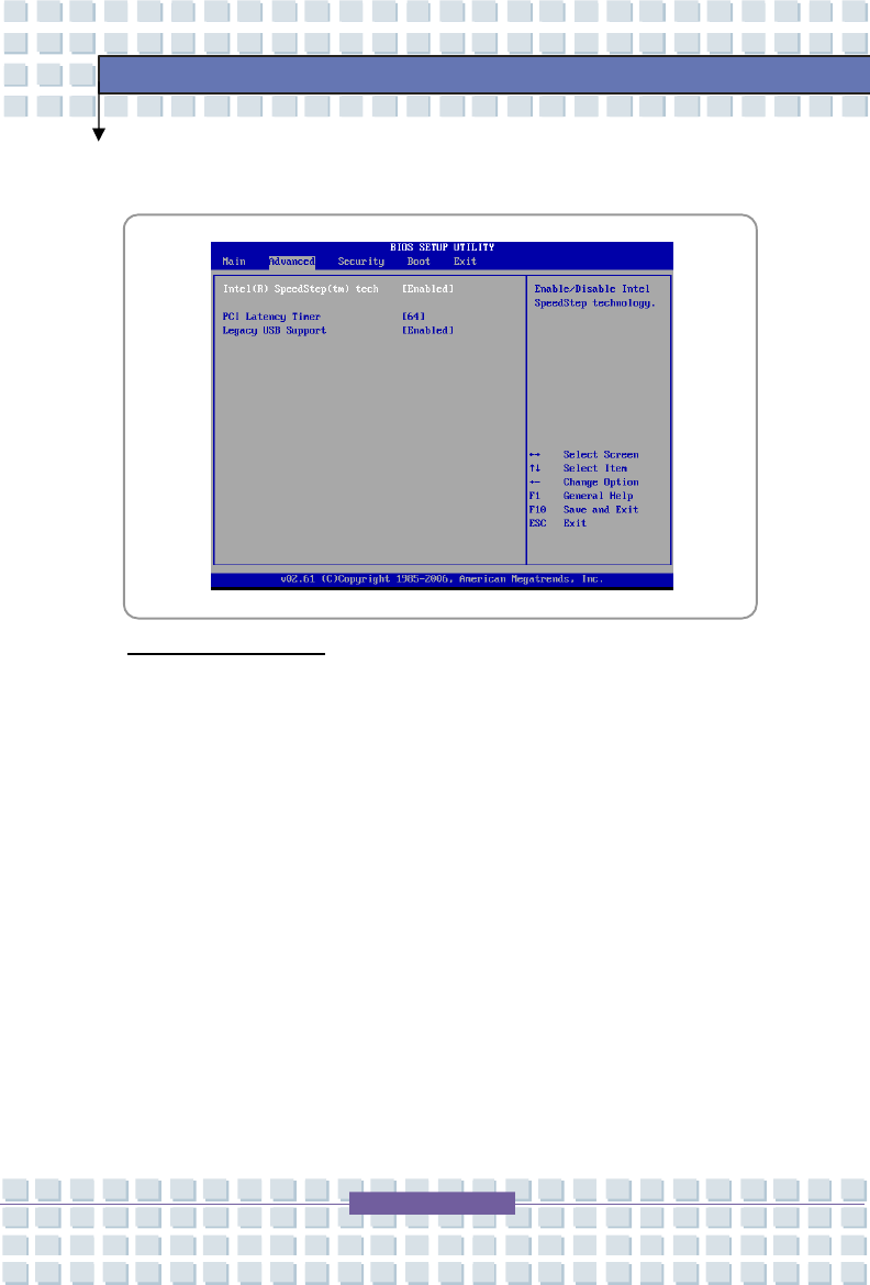
Advanced menu
Advanced Settings
Intel(R) SpeedStep(tm) tech.
This item allows you to enable or disable Intel SpeedStep technology.
When set to Disabled, the system always operates in a conserve power
mode (the processor works at FSB400-600MHz or FSB533-800MHz). If
you want optimize the processor, set this item to Enabled, so that the
processor’s speed will be controlled by the use of your operating system
and applications. Setting options: Enabled, and Disabled.
PCI Latency Timer
Value in units of PCI clocks for PCI device latency timer register.

4
-
8
BIOS Setup
Legacy USB Support
If you want to use USB device, such as mouse, keyboard, portable disk, in
DOS system or boot your system by USB device, you should enable this
function by selecting Enabled.
4
-
9
BIOS Setup
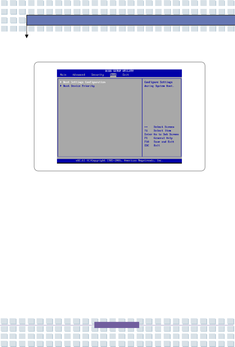
Boot menu
Boot Settings Configuration
Configure settings during system boot.
Boot Device Priority --1st, 2nd, and 3rd Boot Device
The three items allow you to set the sequence of boot devices where BIOS
attempts to load the disk operating system.
4
-
10
BIOS Setup
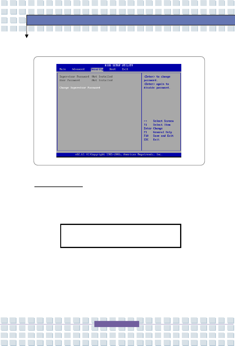
Security menu
Security Settings
Change Supervisor/User Password
When you select the function, a message box will appear on the screen as
below:
Type the password you want, up to six characters in length and press
[Enter]. The password typed now will replace any previously set password
from CMOS memory. You may also press [ESC] to abort the selection and
not enter a password.
Enter
New Password
4
-
11
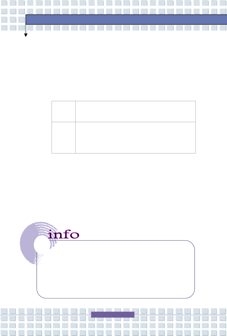
BIOS Setup
When the Supervisor Password is set, the new item User Access Level
and Password Check will be added in the menu. You can make further
settings of access right in the User Access Level item. Setting options:
No Access, View Only, Limited and Full Access. The Password Check
item is used to specify the type of BIOS password protection that is
implemented. Settings are described below:
Setup The password prompt appears only when end users try
to run Setup.
Always
A password prompt appears every time when the
Notebook is powered on or when end users try to run
Setup.
To clear a set password, just press [Enter] when you are prompted to enter
the password. A message box will show up confirming the password will
be disabled. Once the password is disabled, the system will boot and you
can enter Setup without entering any password.
About Supervisor Password and User Password
Supervisor Password allows the user to enter and change the
settings of the setup menu; User Password only allows the user to
enter the setup menu, but do not have the right to make changes.
4
-
12
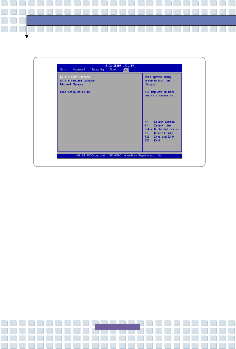
BIOS Setup
Exit menu
Exit & Save Changes
Save the changes you have made and exit the utility.
Exit & Discard Changes
Exit the utility without saving the changes you have made.
Discard Changes
Abandon your changes and reload the previous configuration before
running the utility.
Load Setup Defaults
Select this item to load the default settings for optimal system
performance.