Micro Star MS6855C6 Notebook User Manual F 2007 Communication 6855C EMI
Micro Star International Co Ltd Notebook F 2007 Communication 6855C EMI
UserManual.wiki
>
Micro Star
>
MS6855C6 User Manual
>
User manual 2
Contents
1.
User manual 1
2.
User manual 2
User manual 2
Navigation menu
Upload a User Manual
Namespaces
Wiki Guide
HTML
PDF
Info
Views
User Manual
Discussion / Help
Navigation

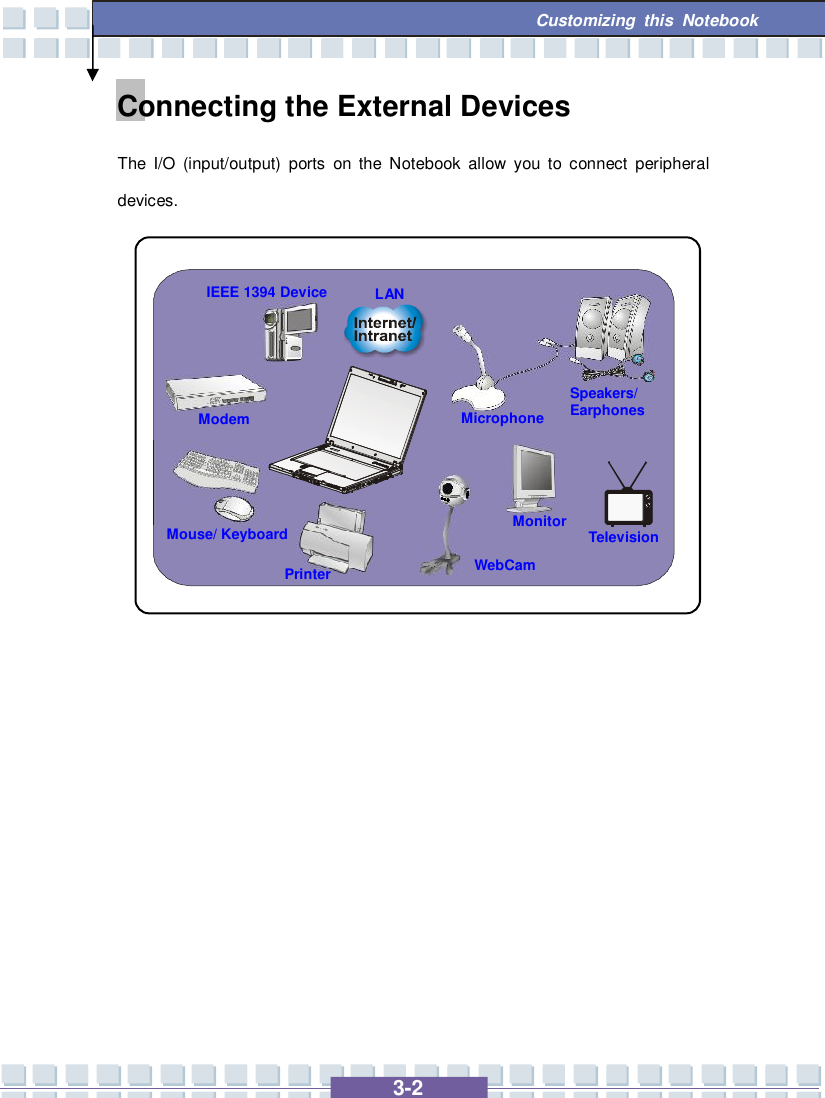
![3-5 Customizing this Notebook Connecting the External Monitor or TV You can connect an external monitor to your Notebook through the DVI-I port for a larger view with higher resolution. To connect the monitor: 1. Make sure that the Notebook is turned off. 2. Plug the monitor’s D-type connector into the Notebook’s VGA port. 3. Connect the monitor’s power cord and turn on the monitor. 4. Turn on the Notebook and the monitor should respond by default. If not, you can switch the display mode by pressing [Fn]+[F2]. Alternately, you can change the display mode by configuring the settings in Display Properties of Windows operating system. Connecting the IEEE 1394 devices The IEEE 1394 port of your Notebook is a next-generation serial bus that features a high-speed transfer rate and the connection of up to 63 devices, allowing you to connect many high-end peripheral devices and consumer electronic appliances, such as the DV (digital video camera). The IEEE 1394 standard interface supports “plug-and-play” technology, so that you can connect and remove the IEEE 1394 devices without turning off the Notebook. To connect the IEEE 1394 device, simply connect the cable of the device to the IEEE 1394 port of your Notebook.](https://usermanual.wiki/Micro-Star/MS6855C6.User-manual-2/User-Guide-807236-Page-20.png)
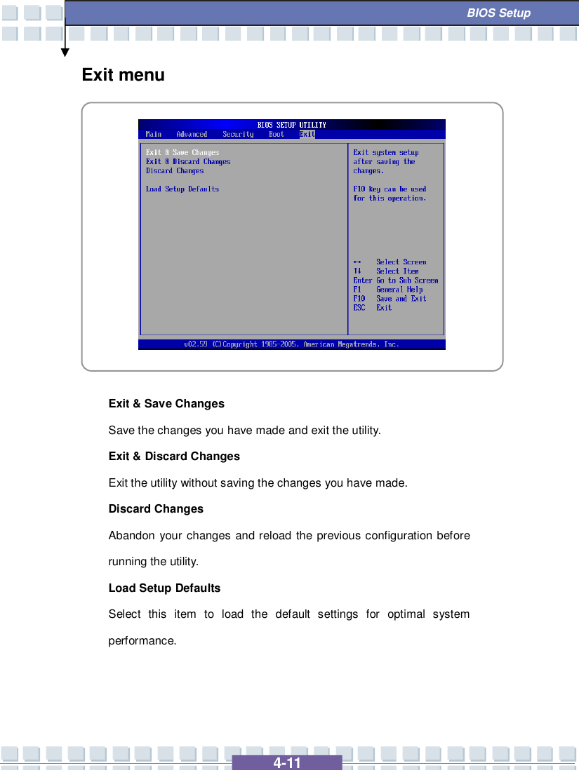
![4-2 BIOS Setup About BIOS Setup When to Use BIOS Setup? You may need to run the BIOS Setup when: w An error message appears on the screen during the system booting up and requests you to run SETUP. w You want to change the default settings for customized features. w You want to reload the default BIOS settings. How to Run BIOS Setup? To run the BIOS Setup Utility, turn on the Notebook and press the [Del] key during the POST procedure. If the message disappears before you respond and you still wish to enter Setup, restart the system by turning it OFF and ON, or simultaneously pressing [Ctrl]+[Alt]+[Delete] keys to restart. The screen snaps and setting options in this chapter are for your references only. The actual setting screens and options on your Notebook may be different because of BIOS update.](https://usermanual.wiki/Micro-Star/MS6855C6.User-manual-2/User-Guide-807236-Page-27.png)
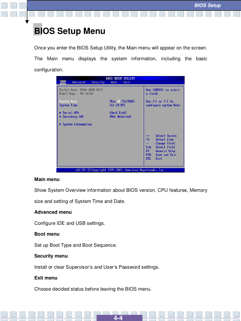
![4-5 BIOS Setup Main menu System Overview System Overview will show you BIOS version and other information about its build date and update notes. Following is CPU’s information about its Type and Speed. System Time This item allows you to set the system time. The system clock will go on no matter you shut down the PC or get into sleep mode. The set format is [hour:minute:second].](https://usermanual.wiki/Micro-Star/MS6855C6.User-manual-2/User-Guide-807236-Page-30.png)
![4-6 BIOS Setup System Date This item allows you to set the system date. The date format is [day:month:date:year]. Day Day of the week, from Sun to Sat, which is determined by BIOS (read-only). Month The month from 01 (January) to 12 (December). Date The date from 01 to 31. Year The year can be adjusted by users. Secondary IDE The item displays the types of the secondary IDE devices installed in the Notebook. Press [Enter] to bring up a window showing the detailed information of the device, including the device name, vendor, LBA mode, PIO mode and more. System Information This item indicates the information of firmware, processor, and system memory.](https://usermanual.wiki/Micro-Star/MS6855C6.User-manual-2/User-Guide-807236-Page-31.png)
![4-9 BIOS Setup Security menu Security Settings Change Supervisor/User Password When you select the function, a message box will appear on the screen as below: Type the password you want, up to six characters in length and press [Enter]. The password typed now will replace any previously set password from CMOS memory. You may also press [ESC] to abort the selection and not enter a password. Enter New Password](https://usermanual.wiki/Micro-Star/MS6855C6.User-manual-2/User-Guide-807236-Page-34.png)
![4-10 BIOS Setup When the Supervisor Password is set, the new item User Access Level and Password Check will be added in the menu. You can make further settings of access right in the User Access Level item. Setting options: No Access, View Only, Limited and Full Access. The Password Check item is used to specify the type of BIOS password protection that is implemented. Settings are described below: Setup The password prompt appears only when end users try to run Setup. Always A password prompt appears every time when the Notebook is powered on or when end users try to run Setup. To clear a set password, just press [Enter] when you are prompted to enter the password. A message box will show up confirming the password will be disabled. Once the password is disabled, the system will boot and you can enter Setup without entering any password. About Supervisor Password and User Password Supervisor Password allows the user to enter and change the settings of the setup menu; User Password only allows the user to enter the setup menu, but do not have the right to make changes.](https://usermanual.wiki/Micro-Star/MS6855C6.User-manual-2/User-Guide-807236-Page-35.png)