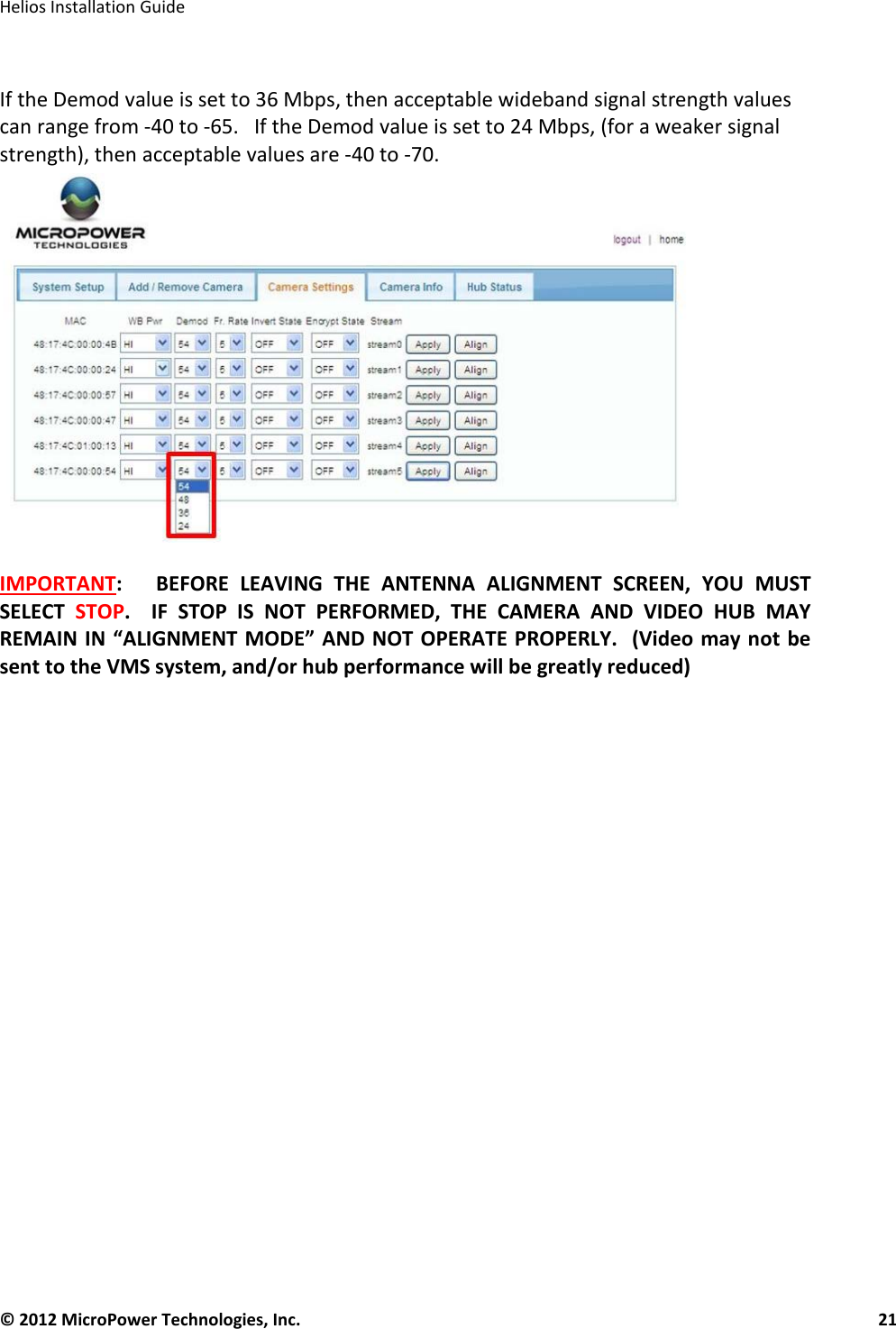
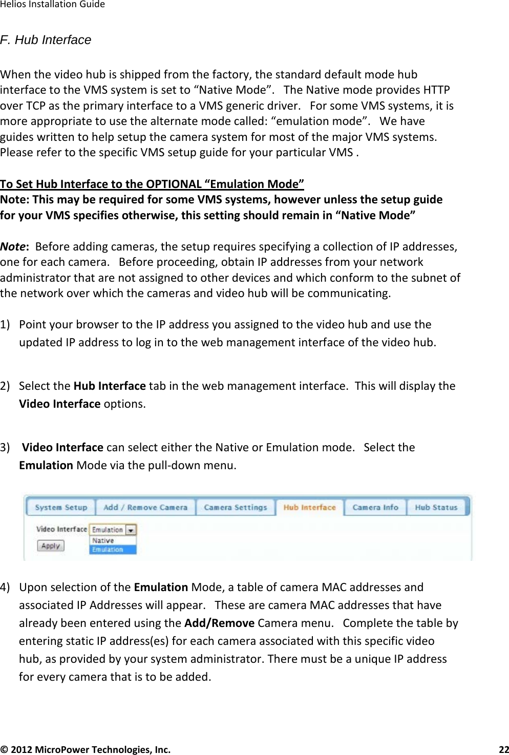
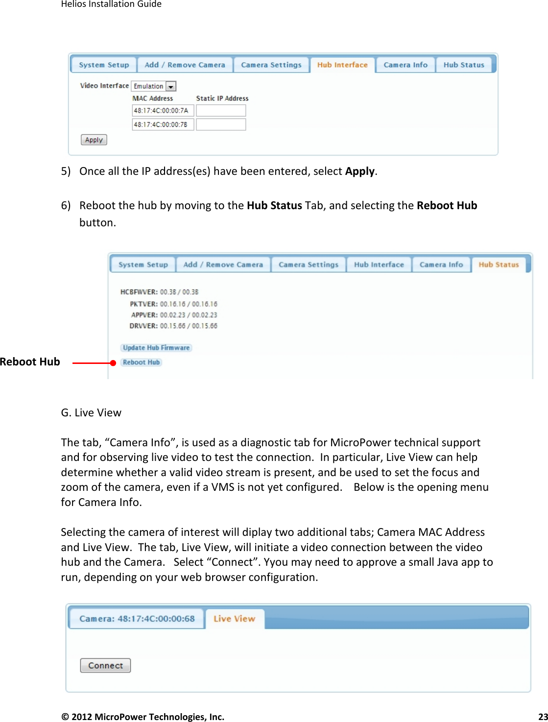
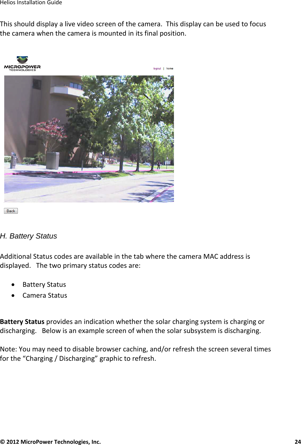
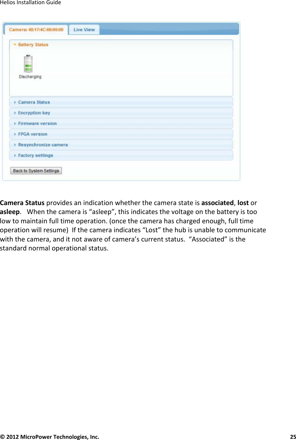
MicroPower Technologies MPT2700A MicroPower Mini-Hub User Manual 4225 Executive Square Ste

MicroPower Technologies, Inc. MicroPower Mini-Hub 4225 Executive Square Ste

User Manual

   © 2012 MicroPower Technologies, Inc.      1    4350 Executive Drive, Ste. 325 San Diego, CA 92121 +1-888-854-3312 www.micropower.com            Helios™  Solar Wireless IP Surveillance System   Installation Guide Version 5.12
  Helios Installation Guide  © 2012 MicroPower Technologies, Inc.      2      Table of Contents   Contacting MicroPower Customer Support ................................................................................ 3 General Safety Precautions .......................................................................................................... 3 Package Contents ......................................................................................................................... 4 Installation Recommendations .................................................................................................... 6 I. Site Survey ........................................................................................................................ 6 II. System Setup .................................................................................................................... 9 A.  Accessing the Intelligent Video Hub ....................................................................... 10 B.  System Setup via the Video Hub ............................................................................. 10 C.  Add/Remove Cameras .............................................................................................. 15 D.  Camera Settings ........................................................................................................ 17 E. Align Mode .................................................................................................................. 18 F. Hub Interface .............................................................................................................. 22 G. Live View..................................................................................................................... 23 H. Battery Status ............................................................................................................. 24 III. Mounting the Video Hub’s External Antenna .............................................................. 26 IV.    Mounting the Camera ..................................................................................................... 29 V. Mounting the Auxiliary Solar Panel .............................................................................. 30 VII. Configure the Video Management Software (VMS) ..................................................... 33 REGULATORY AND LICENSING INFORMATION ..................................................................... 34
  Helios Installation Guide  © 2012 MicroPower Technologies, Inc.      3    Contacting MicroPower Customer Support   MicroPower’s customer support strategy is through best-in-class business partners including OEMs, distributors, systems integrators and systems vendors.  If your MicroPower product was purchased directly from a MicroPower business partner, that partner is the first point of contact for technical support.  If the business partner cannot resolve a problem, then the partner will contact MicroPower.  Web Support:  http://www.micropower.com Email Support:   help@micropower.com Phone Support Worldwide: +1-888-854-3312 Fax Support – Worldwide: +1-858-947-3907  General Safety Precautions   •  Follow all cautions, instructions, and warnings as listed on the product and related documentation, including electro-static discharge (ESD) recommendations, physical handling advice and other recommendations or best practices.  •  Ensure that the voltage and frequency of your power source match the voltage and frequency required by the equipment.  Do not use alternative power supplies without first contacting MicroPower.  •  Do not attempt to modify or change the internal batteries.  The battery size and voltage are calculated to match the size, voltage, and runtime required by the equipment.  Modifying the battery system could result in damage to the equipment and nullification of the product warranty.  •  Use only the included antennas and ancillary equipment provided with the product.  •  Do not make mechanical or electrical modifications to equipment. MicroPower is not responsible for the safety or regulatory compliance of a modified product.   •  Do not omit device components that would interfere with air flow and cooling as designed. Failure to follow these guidelines can cause overheating and affect the reliability of your MicroPower product.  •  Protect your warranty.  A product which has been damaged, misused, abused or misapplied may be determined to be out of warranty.
  Helios Installation Guide  © 2012 MicroPower Technologies, Inc.      4   Package Contents  The MicroPower Solar Wireless Surveillance System consists of two major devices; the MPT2500 Series Solar Wireless IP Video Camera and the MPT2700 Series Intelligent Video Hub.   Solar Wireless Video Camera (MPT2500 series)  • Solar Wireless Video Camera/ IP66 Enclosure  (Including 2 Philips screws for attaching the bracket to the camera housing) • Camera Mounting Arm  o Wall attachment screws and bracket screws utilized to adjust the camera position and angle • One Dual Frequency Directional Antenna (900MHz / 2.4GHz) o U-Bracket with washers and screws o Antenna Cable • Antenna Arm Bracket Assembly (Installer should supply stainless steel worm drive bands “hose clamps” in appropriate size for mounting pole).  Intelligent Video Hub (MPT2700 series)   • Intelligent Video Hub o Power Brick, Mounting Hardware, Documentation o Antenna Cable Splitter and SMA Adapters o Antenna Cable • One Dual Frequency Directional Antenna (900MHz / 2.4GHz) o U-Bracket with washers and screws o Antenna Cable • Antenna Arm Bracket Assembly (Installer should supply stainless steel worm drive bands “hose clamps” in appropriate size for mounting to the pole).
  Helios Installation Guide  © 2012 MicroPower Technologies, Inc.      5   System Overview  MicroPower Technologies has developed a unique proprietary power and wireless technology called “TrustLinx™”, which enables the long-range wireless transmission of digital video while using only 10% of the electrical energy that most common wireless IP cameras consume.  With this patented technology, the MicroPower wireless Video cameras can remain fully operational for up to five days in complete darkness, utilizing only the internal rechargeable batteries. This enables the camera to reliably operate 24 hours a day through most weather conditions, without any performance loss or need for maintenance.  Additionally, the TrustLinx radio technology does not conflict with other wireless technologies such as traditional Wi-Fi (802.11b/a/c/n), while still retaining the ability to reliably transmit high-quality digital video up to distances of 1/2 mile.   The patented TrustLinx technology eliminates the need for trenching and/or long cable runs to remote outdoor cameras, significantly reducing installation time, labor costs, and allowing cost effective remote video coverage in locations where surveillance was never before possible.   In the 2.4 GHz ISM band, referring to the OSI 7 layer networking model, we use Layer 1 for the physical layer and Layer 2 for the data link layer.  We do not use Layer 3 (network layer), Layer 4 (transport layer) or Layers 5-7.  Therefore, we utilize the physical radio and the data link that organizes the bits into packets.  These packets are not Wi-Fi, TCP/IP or any other topology.  The hub receives the packets from the camera and although the packets comply with the 802.11 Layer 2 data link format, the content is proprietary. Because we are receiving camera data it is a one way stream from the camera to the hub. We do not enable the transmit from the hub to the camera using this radio, therefore the normal mode of operation and the only mode that can be activated by the user is receive mode.  The MicroPower designed card is designated the Hub Controller Board, or HCB. It is also a mini PCIe card. The HCB is controlled by an on-board microcontroller. The microcontroller has direct access to a 915MHz radio transceiver. The operating frequency of the radio is derived from a 48MHz crystal, and FSK modulation is employed. The radio is coupled with a power amplifier and LNA to boost output power to approximately 13dBm. Matching and filtering networks are employed to minimize spurious noise and harmonics. One of multiple channels in the 909-921MHz ISM band can be selected for operation. This allows the system to select a channel to avoid interference with other devices operating in the band. The channel selection is determined by software on the host computer and communicated with the HCBs microcontroller using an internal USB interface.  Up to six (6) wireless cameras can be associated to a single video hub.  The video hub is the only data connection point to which the Video Management System (VMS) will communicate and obtain the remote video streams.  The standard TCP/IP data from the
  Helios Installation Guide  © 2012 MicroPower Technologies, Inc.      6   video hub, may be transmitted via Ethernet through virtually any conventional broadband network technology (LAN, T1, ADSL modem, cable modem, cellular modem, mesh network, etc. to your chosen VMS solution)   Installation Recommendations  There are 5 major steps that are recommended for a successful installation.   These are:  1. Site survey 2. System setup 3. Mounting the video hub and wireless camera(s), and solar panels 4. Adjusting the zoom/focus/iris of the camera 5. Configuring the VMS  I. Site Survey  A well-thought out plan for the location of the hub and camera(s) is an important step to ensuring that the entire system will remain operational, and integrate with a new or pre-existing video management system.    For a more complete guide on performing a
  Helios Installation Guide  © 2012 MicroPower Technologies, Inc.      7   quality site survey, please refer to the MicroPower documentation titled “Site Survey Guidelines”.  With unobstructed line-of-sight between the hub and camera antennas, the system can reliably transmit video up to 1/2 mile in distance.   However, obstacles such as trees, buildings, fences, etc. will impact the wireless performance in terms of maximum transmission distance and data rate speeds.  Once a video link is established, if obstructions are present, or the distance between the antennas is too great, then the video streams may experience dropouts and/or reduced camera frame rates.   A wall or tree may not cause any significant performance impact at short ranges, yet can completely block a signal at long distances.  Additionally, for best extremely short range performance, the minimum distance between the video hub antenna and the wireless Camera antenna should be 25 feet (unless signal attenuators are installed).     For further education and guidelines on RF effects, refer to MicroPower document “A Guide to Optimizing Your RF Setup”.   Since the wireless camera is powered by solar energy, the critical impact of sun direction and shadows on the panels cannot be overstated.  It is advisable that the camera be positioned in such a way that two or more of the built-in solar panels receive adequate direct sunlight during the peak charging hours from 11 a.m. to 3 p.m.   When selecting a location for the wireless camera that will be installed in the Northern Hemisphere, the auxiliary solar panel must be mounted on the SOUTH side of a pole or structure, facing SOUTH.  With the camera’s built-in solar panels, it is also preferable to mount the camera on the South side of the pole, to minimize shadows created by the pole, and to ensure good light coverage across all of the panels as the sun moves across the sky.  For East or West facing cameras, try to mount the camera on the South side of the pole, and point the camera in the desired direction.  For optimum solar performance, always try to avoid the North side of the pole.  (In the Southern Hemisphere below the equator, the directional considerations are reversed)  Areas with insufficient direct sunlight will eventually produce camera outages, such areas include, but are not limited to: • Solar panels shaded under a roof eave • Underneath a tree canopy or foliage which does not receive adequate sunlight • Next to a tall building that casts a shadow over the camera during peak charge times. (Particularly during the important mid-day charging period) • A camera mounted such that the pole that it is attached to, or other area objects (wires, cables, etc.) cast shadows across multiple solar panels during peak charge times.
  Helios Installation Guide  © 2012 MicroPower Technologies, Inc.      8   Keep in mind that the cameras include a powerful battery backup capable of operating the camera over (5) days in complete darkness.  If the system is receiving light, but at levels that are below the “break even” point, operation time can potentially be extended for weeks before a camera is finally no longer be able to remain operational 24/7.  Thus, it is important to be aware that a camera may appear to operate fine in poor lighting conditions, when in fact it is slowly discharging.    Sufficient daytime lighting is absolutely critical to the long-term successful operation of the system.  Additionally, making sure there are no shadows cast on the panel during the day also plays a critical role to success.  Solar panels, by their nature, are sensitive to and greatly affected by shadows (even very small ones) on the panel.  The most common difficulties we help troubleshoot in the field can usually be attributed directly to solar panel shadowing.    (Note: In the next section, we will detail how to log into the hub and view the charging status of each camera to help determine if lighting levels are sufficient.)
  Helios Installation Guide  © 2012 MicroPower Technologies, Inc.      9   II. System Setup  The following steps are required when performing system setup and installation.   1. Connect the antennae to the video hub 2. Configure video hub to the desired IP address/network settings. 3. Reboot the hub system.  4. Add the camera(s) MAC address through the hub’s web interface.  5. Connect the camera antenna and camera power to test the each camera prior to mounting and installation.  6. View the camera connection through the web interface and Live Connection (Perform basic adjustments to camera zoom/focus settings if necessary).  7. Mount the video hub in a secured, climate controlled location, run the hub antenna cable, mount and adjust hub antenna. 8. Begin camera, antenna, and solar panel mounting, and adjust antenna alignment at the final remote installation locations.
  Helios Installation Guide  © 2012 MicroPower Technologies, Inc.      10   A.  Accessing the Intelligent Video Hub  Accessing the video hub is similar to setting up a wireless router in your home, in that a web-based display is used to control the device.  There are two basic methods for connecting to the video hub, with or without an Ethernet network switch.  The most common method for systems which already have a pre-existing network in place is by addressing the video hub through a network switch.  It is also possible to communicate with the video hub from a server directly, by using a crossover cable.   Below are illustrations of both topologies.                  Configuration 1     Configuration 2  B.  System Setup via the Video Hub  It is important to configure the video hub first, prior to pairing the video hub to the wireless cameras.  System setup is performed via a standard web browsing application such as Mozilla Firefox, or Google Chrome, similar to how a wireless router is configured in a home environment. (Internet Explorer is not recommended for system setup).      Note:  Though the video hub is a fully operational Linux server, for support and performance purposes, MicroPower requires that hub software installations remain consistent.  As such, the installation of additional software to, or modification of the core video hub software will nullify the MicroPower Technologies warranty.       DisplayServer NetworkSwitch HubCameraDisplayServer CrossoverCable HubCameraAntenna Connector Antenna Connector  Ethernet Network Port  DC Power
  Helios Installation Guide  © 2012 MicroPower Technologies, Inc.      11   To configure the video hub, you will need to:  1. Connect  video hub Antenna 2. Connect the AC power cable to the video hub and plug into a power source. 3.  Power on the video hub by briefly pressing the power button on the rear of the unit.    If the camera is powered on, make sure the wireless camera and video hub antennas are at least 25 feet away from each other.  4. Connect your computer to the hub via the Ethernet port, and configure your computer network settings so that it can directly address the video hub.   Below is an example screen of modifying the IPv4 IP address properties in Windows to make this change.         Press OK.
  Helios Installation Guide  © 2012 MicroPower Technologies, Inc.      12    1. To communicate with the video hub, type the default IP address of the video hub into your web browser as though you were trying to visit a website.  (For best results, use Firefox or Chrome).  http://192.168.0.100    This is a temporary IP address which you will likely need to change via the system setup application.     At this point, a login screen will appear.       Type in admin for the username.  The password is left blank.
  Helios Installation Guide  © 2012 MicroPower Technologies, Inc.      13     2. Begin configuration of the video hub by selecting the System Setup tab.     This is the menu used to specify the final IP address, hostname, wideband channel, wideband bandwidth, narrowband channel number, narrowband channel power and time out period.    The other variables (Wideband Channel, Demod Level, Narrowband Chan, Narrowband Pwr) are selectable, but generally should not need to be changed.   Typically, you will only need to modify the IP address to be compatible with your current network configuration.   To configure the IP address, single click the IP address button in the window, you will then be directed to the Configure Hub IP Address menu. (shown below)    This menu allows a user to modify a static IP address, gateway address, and subnet address or, to choose “Use Dynamic” otherwise known as DHCP.   Note:  Do not forget your IP address, and use caution if you choose “Use Dynamic”.  Your VMS system will need to be able to locate the video hub, and if a DHCP server is dynamically assigning different IP addresses to the hub, it can cause the hub to be difficult to find on the network.  Only use this setting if your network administrator has told you to, AND, can determine and/or control the appropriate IP address issued to the video hub.  In most installations, static (non-changing) IP addresses are most common, and the preferred choice for the Hub.
  Helios Installation Guide  © 2012 MicroPower Technologies, Inc.      14   Typically, the new hub IP address should correspond to the IP address within the subnet of your VMS network (the first three sets of numbers match).   For example, should some of your network devices be assigned an IP address similar to: 192.168.100.2, 192.168.100.5 or 192.168.100.10, then a viable Hub IP address could be 192.168.100.150 or perhaps 192.168.100.8.  This allows other devices within your local network, including the NVR, to communicate with each other.     Input the desired IP address and click Update.   (if a dialog box warns that you will need to restart the hub, just click ok and continue)  After updating the “Configure Hub IP Address menu”, you will be directed to the previous menu, System Setup.     You will then need to click Apply here as well to apply the IP address change you previously made.  You should then see a dialog alert informing you that a system reboot is required, since the video hub will not be configured for the new IP address until a reboot is complete.    To perform the required reboot, navigate to the Hub Status tab, scroll down, and click to restart the hub.  (You may need to verify/confirm that setting a second time)  Close the HTML browser window, wait approximately 1-2 minutes for the restart process to complete.   3. You can now attempt to access the hub on the newly configured IP address.  Note that you will need to change back the IP settings of your computer to match the IP range of the new video hub IP address, before you will be able to access the hub.  The administration login screen should again appear.   If there is a problem, and you are unable to connect to the video hub, then double check that you have changed the IP address settings of your computer to match the range of the video hub’s “new” IP address.    If you are still unable to access the hub, it is possible that both the “apply” or the “update” button may not have been clicked during IP address change procedure on the video hub. If this is the case, the IP change process will need to be repeated.
  Helios Installation Guide  © 2012 MicroPower Technologies, Inc.      15   C.  Add/Remove Cameras  This is the menu used to add or remove cameras that are associated with the specific hub that is being configured.   1. Select Tab labeled Add/Remove Camera.   2. Select option to “Add New”.   A pop-up window for the MAC address of the camera is displayed.         Add the MAC Address that is printed on the sticker of the wireless camera.   The sticker is located both on the inside and the outside of the camera enclosure.   Press OK when the MAC address is entered.   1.  Follow Step 3 again to add additional cameras (maximum of 6)  2. Connect the antenna(s) to the camera(s)  3. Inside the camera enclosure, connect the battery cable to the camera circuit board connector. The camera ships with a fully charged battery pack, however, when the
  Helios Installation Guide  © 2012 MicroPower Technologies, Inc.      16   wireless camera is shipped from the factory, the battery is disconnected from the battery camera to ensure it remains fully charged.    When the battery is connected to the camera, an LED indicator light (on the left side while peering inside the camera) should glow red when the battery is connected.    4. If you wish to do an initial camera focus / zoom adjustment, you can leave the camera open.  Otherwise, close the camera housing then lock the safety latch.    NOTE:  When closing the housing, be careful not to crush any cables in the housing hinges or edge seals, and make sure the various water-tight seals remain in place on the edges of the housing. (particularly at the front of the camera near the hinges)   Helpful Tip: Make a note of the MAC address in your records.  (If you ever need to re-set up the hub, it is helpful to have these numbers written down, instead of having to visit each camera after it has been installed)
  Helios Installation Guide  © 2012 MicroPower Technologies, Inc.      17   D.  Camera Settings  The tab, “Camera Settings” is used to customize each wireless camera associated with the paired video hub.   1. Select tab labeled Camera Settings.    Variables for the Camera Settings beyond the MAC address are:  Variable Description Valid value for wireless cameras MAC  Camera MAC Address Six Hex values WB Power Power settings for the Wideband signal Hi, Med, Lo Demod Data bandwidth of the individual cameras 54, 48, 36, 24 Mbps Fr. Rate Frame rate desired. (Fixed at 5fps) Invert State Specifies whether the video is an inverted image or not.  Off  Encrypt State Will allow the encryption of data sent between the wireless and video hub . (Inactive: Future Development Feature) Off Stream Displays the stream # of the camera. (This information is needed to set up most VMS configurations) StreamX where X can be 0 to 5  Use the “Apply” button at the end to apply new settings for that specific camera.   Helpful Tip:  Make a note of the stream numbers associated with each of your cameras, it is helpful to have when setting up the VMS software.   The “Align” button is used for aligning antennas, and is covered in the next section.
  Helios Installation Guide  © 2012 MicroPower Technologies, Inc.      18    E. Align Mode  The last button, “Align”, is a special function for determining the best antenna alignment and signal quality between the video hub and  wireless camera.  The web interface allows the user to see the narrowband and wideband wireless performance for each individual camera.      This mode is especially useful while performing the installation, optimizing the camera, video hub, and determining antenna location and adjustment for the best performance for each camera.    By selecting “Align”, the user will be directed into a new menu set that provides gauges, showing radio measurements for the signal power, quality and noise of the 900MHz narrowband (NB Signal) and wideband 2.4GHz (WB Signal) link.   The opening menu will look like the example below.
  Helios Installation Guide  © 2012 MicroPower Technologies, Inc.      19   The meters are defined as you move left to right; top to bottom:  • NB Signal (cam) = (915 MHz) signal strength received by the camera  • NB Signal (hub) = (915 MHz) signal strength received by the video hub  • NB Quality (cam) = (915 MHz) signal quality received by the camera  • NB Quality (hub) (915 MHz) signal quality received by the video hub • WB Signal = (2.4 GHz) signal strength • WB Noise =  (2.4 GHz) noise level • WB Quality =  (2.4 GHz) signal quality Note:  Most cameras are configured with a single “Dual band” antenna that handles both frequencies that the camera utilizes.   The steps for optimizing the alignment of the camera and video hub are:  1. Click “Start” to begin monitoring the wireless performance for a specific camera 2. Make sure the antenna position maximizes the signal strength (note there is a 4 second delay from an adjustment being made, until the result may be seen on screen) 3. Click “Stop”, followed by “back” when finished making adjustments. 4. Wait for the button to change from “resetting” back to “align”  IMPORTANT:   BEFORE LEAVING THE ANTENNA ALIGNMENT SCREEN, YOU MUST SELECT STOP.  IF STOP IS NOT PERFORMED, THE CAMERA AND VIDEO HUB MAY REMAIN IN “ALIGNMENT MODE” AND NOT OPERATE PROPERLY.  (Video may not be sent to the VMS system, and/or hub performance will be greatly reduced)
  Helios Installation Guide  © 2012 MicroPower Technologies, Inc.      20    Signal Strength Expectations  Overall Goal:  Adjust the antenna such that the narrowband and wideband signal strength and quality levels are as high as possible.     Narrowband strength acceptable ranges are -15 to -70.   -15 is better, higher strength signal than -70 (closer to zero).   The values of the NB signal strength received by the camera and video hub are typically expected to be approximately the same value.   Narrowband quality values above 35 should yield an acceptable operation. But this can vary depending on the RF environment.  A Wideband signal strength within the range of -40 to -65 will typically yield very solid performance.   Wide Band signal strength should also be as high (closer to zero) as possible.   Acceptable ranges vary by environment.     DEMOD Value:  A lower Demod value will help permit operation at greater distances, or at weaker signal levels.  The trade-off with a lower Demod rate however, is the length of time required to send data packets will be longer, allowing for a greater chance of interference.  Depending on the RF environment, this can ultimately result in a lower average frame rate. (dropped frames)
  Helios Installation Guide  © 2012 MicroPower Technologies, Inc.      21    If the Demod value is set to 36 Mbps, then acceptable wideband signal strength values can range from -40 to -65.   If the Demod value is set to 24 Mbps, (for a weaker signal strength), then acceptable values are -40 to -70.     IMPORTANT:   BEFORE LEAVING THE ANTENNA ALIGNMENT SCREEN, YOU MUST SELECT  STOP.  IF STOP IS NOT PERFORMED, THE CAMERA AND VIDEO HUB MAY REMAIN IN “ALIGNMENT MODE” AND NOT OPERATE PROPERLY.  (Video may not be sent to the VMS system, and/or hub performance will be greatly reduced)
  Helios Installation Guide  © 2012 MicroPower Technologies, Inc.      22   F. Hub Interface  When the video hub is shipped from the factory, the standard default mode hub interface to the VMS system is set to “Native Mode”.   The Native mode provides HTTP over TCP as the primary interface to a VMS generic driver.   For some VMS systems, it is more appropriate to use the alternate mode called: “emulation mode”.   We have guides written to help setup the camera system for most of the major VMS systems.  Please refer to the specific VMS setup guide for your particular VMS .    To Set Hub Interface to the OPTIONAL “Emulation Mode”  Note: This may be required for some VMS systems, however unless the setup guide for your VMS specifies otherwise, this setting should remain in “Native Mode”  Note:  Before adding cameras, the setup requires specifying a collection of IP addresses, one for each camera.   Before proceeding, obtain IP addresses from your network administrator that are not assigned to other devices and which conform to the subnet of the network over which the cameras and video hub will be communicating.  1) Point your browser to the IP address you assigned to the video hub and use the updated IP address to log in to the web management interface of the video hub.  2) Select the Hub Interface tab in the web management interface.  This will display the Video Interface options.   3)  Video Interface can select either the Native or Emulation mode.   Select the Emulation Mode via the pull-down menu.     4) Upon selection of the Emulation Mode, a table of camera MAC addresses and associated IP Addresses will appear.   These are camera MAC addresses that have already been entered using the Add/Remove Camera menu.   Complete the table by entering static IP address(es) for each camera associated with this specific video hub, as provided by your system administrator. There must be a unique IP address for every camera that is to be added.
  Helios Installation Guide  © 2012 MicroPower Technologies, Inc.      23     5) Once all the IP address(es) have been entered, select Apply.   6) Reboot the hub by moving to the Hub Status Tab, and selecting the Reboot Hub button.     G. Live View  The tab, “Camera Info”, is used as a diagnostic tab for MicroPower technical support and for observing live video to test the connection.  In particular, Live View can help determine whether a valid video stream is present, and be used to set the focus and zoom of the camera, even if a VMS is not yet configured.    Below is the opening menu for Camera Info.   Selecting the camera of interest will diplay two additional tabs; Camera MAC Address and Live View.  The tab, Live View, will initiate a video connection between the video hub and the Camera.   Select “Connect”. Yyou may need to approve a small Java app to run, depending on your web browser configuration.   Reboot Hub
  Helios Installation Guide  © 2012 MicroPower Technologies, Inc.      24   This should display a live video screen of the camera.  This display can be used to focus the camera when the camera is mounted in its final position.      H. Battery Status  Additional Status codes are available in the tab where the camera MAC address is displayed.   The two primary status codes are:  • Battery Status  • Camera Status  Battery Status provides an indication whether the solar charging system is charging or discharging.   Below is an example screen of when the solar subsystem is discharging.   Note: You may need to disable browser caching, and/or refresh the screen several times for the “Charging / Discharging” graphic to refresh.
  Helios Installation Guide  © 2012 MicroPower Technologies, Inc.      25     Camera Status provides an indication whether the camera state is associated, lost or asleep.   When the camera is “asleep”, this indicates the voltage on the battery is too low to maintain full time operation. (once the camera has charged enough, full time operation will resume)  If the camera indicates “Lost” the hub is unable to communicate with the camera, and it not aware of camera’s current status.  “Associated” is the standard normal operational status.
  Helios Installation Guide  © 2012 MicroPower Technologies, Inc.      26    III. Mounting the video hub’s External Antenna  For professional, reliable installations, the video hub should use the external antenna supplied with the unit.  The MicroPower external antenna kit comes complete with a low loss RF cable, 2:1 splitter and a directional antenna.  For optimal results, the height of the external antenna should be mounted above any pedestrians, vehicle traffic, trees, or obstacles that may block line-of-sight between the video hub and wireless camera(s).  The directional antenna supplied by MicroPower can transmit and receive in both the 900 MHz and 2.4 GHz frequencies.    However, the 900 MHz and 2.4 GHz channels from the video hub must be combined before being connected to the directional antenna.    In order to connect the channels together, a 2:1 splitter (included) must be used.   The 2:1 splitter must be connected as shown below.  The output of the 2:1 splitter is connected to the low loss RF cable.   This will generally simplify the installation, by not requiring that the installer mount and configure two separate antenna solutions, and not requiring that two independent antenna cables be used.
  Helios Installation Guide  © 2012 MicroPower Technologies, Inc.      27   Directional Antenna Specifications  The directional antenna can be mounted vertically, or in a horizontal (flat) position.  We find better performance by mounting all the antennas flat, where they are less likely to be moved by the wind.  However the antennas are mounted, it is very important that all the antennas be oriented IN THE SAME ORIENTATION. (Either all horizontal, or all vertical)  Each antenna should be connected directly to the camera / hub, one antenna per device.    The directional antennas when placed horizontally have an approximate 70 degree field of view, and when placed vertically have a 50 degree field of view. The camera antennas should be positioned pointing toward the hub within the “cone” of the hub’s antenna, for the system to properly communicate. (Note that the camera’s antennas should point only to the hub antenna, not to each other).  The directional antennas are mounted to the curved pole bracket via the included mounting hardware.  The curved bracket will then need to be mounted to the desired location, using hardware supplied by the installer.  Most typically this would be done via stainless steel hose clamps, “U” bolts, or some other clamping mechanism.
  Helios Installation Guide  © 2012 MicroPower Technologies, Inc.      28
  Helios Installation Guide  © 2012 MicroPower Technologies, Inc.      29   IV.   Mounting the Camera    When mounting the camera, it should be placed in an area which receives an adequate amount of direct sunlight throughout the day.  Ideally the camera should be placed on the south side of the mounting location, and pointed in the desired direction.  Next best choices are mounting to the east or west sides, with a North facing mount orientation considered last.  This practice will maximize the benefit of the built-in solar panels.  The included auxiliary external solar panel will provide most of the charge, with the built-in panels assisting.  It is critical that the external solar panel be mounted correctly, facing the right direction for the camera to run successfully, long-term.  (Instructions for mounting the panel are covered in the next section)  For easiest mounting of the camera, we suggest the following steps. 1. Remove the rotating/pivoting camera hinge from the bracket, by removing the single center Phillips screw that holds it in place. 2. Attach the rotating/pivoting bracket to the camera housing, and position it such that the camera is weight balanced and the bracket is tightened. 3. Mount the arm bracket to the desired location.  Self-tapping screws, or stainless steel “worm drive hose clamps” work very well for this purpose. 4. Place the camera housing on the secured bracket. If the camera is balanced, and the bracket tightened, it will take very little effort to hold it in place while attaching the center screw that holds the camera in place. 5. Aim the camera and tighten the screw, securing the rotating/pivoting bracket to the camera arm bracket. 6. Make final adjustments to the angle and rotation position of the camera, zoom and focus if required.  After securely tightening the screws, the locking ridges in the mounting bracket will hold the camera securely in position after it is installed.
  Helios Installation Guide  © 2012 MicroPower Technologies, Inc.      30   V. Mounting the Auxiliary Solar Panel   The auxiliary solar panel is included with the camera, and is designed to augment the built-in solar charging system of the MicroPower wireless cameras.  It offers greater flexibility with the placement of the camera, and enables reliable operation in install locations that may have lower light levels such as: North facing cameras, or northern climates where snow and ice may impact the long-term operation of solar powered devices.  The solar panel connects to the camera very easily, and may be secured to a variety of different surfaces by a very simple, yet extremely versatile mounting bracket.   Where to Mount the Auxiliary Solar Panel:  For mounting locations in the Northern Hemisphere (United States, Mexico, Canada, etc.) The Solar panel should be mounted with the glass facing SOUTH, and angled such that it will capture the most winter sun possible during the daylight hours.  The farther North the panel is located, the lower in the horizon the panel should be angled.  Climates where snow and ice are a factor will also need to angle the panel more sharply, such that snow will not tend to accumulate on the panel glass.  It is very important that care is taken to ensure that objects such as trees, utility poles, buildings, wires, etc. do not create any shadows on any of the solar panels in the system.  Additionally, the solar panel should be mounted such that shadows created by the panel do not cover the camera’s built-in solar panels, but most importantly, shadows created by the camera (or other objects) do not impact the larger auxiliary solar panel.    Note: The battery ships from the factory at about 40% capacity.  For storage and shipment, the battery remains unplugged from the camera, and will need to be connected to power on the camera.  When the camera is stored out of sunlight, the battery should be disconnected.
  Helios Installation Guide  © 2012 MicroPower Technologies, Inc.      31   How to Mount the Auxiliary Solar Panel:  The solar panel mounting bracket is extremely versatile, and is designed to be used with stainless steel hose clamps, “U” bolts, or screws to firmly secure the panel to the desired mounting surface.   Always be sure that the panel is firmly secured against weather events such as high winds, ice, snow, etc.  Depending on your particular configuration, the installer will need to purchase the appropriate hardware to attach the bracket to the desired mounting surface.  The images below illustrate the various mounting configurations that are possible with this bracket.
  Helios Installation Guide  © 2012 MicroPower Technologies, Inc.      32   VI.   Adjusting the Camera Image     Camera Lens Close-up View  1. While viewing the camera image through the Video Management System (VMS) camera image window, adjustments can be made to the camera’s zoom, iris or focus.  2. Open the camera housing using the safety latch at the rear of the unit. The camera imager is located just behind the glass housing window.  2.1 To adjust focal length (zoom), loosen the focal length locking knob counter-clockwise.  Rotate the focal length adjustment ring at the rear of the lens (the ring, not the knob) to adjust.    2.2 To adjust iris, turn the iris lock knob counter-clockwise to release.  Slide the iris locking knob to the right or left to set.  (The “O” open setting is best for achieving good low light camera performance.)  2.3 To focus, turn the focus lock knob counter-clockwise to unlock.  Rotate the focus adjustment ring at the front of the lens to adjust.  Typically both focus and zoom will need to be adjusted at the same time to achieve the desired field of view.  Lock knobs need only be lightly tightened to hold the lens settings in place.  2.4 After the imager adjustments have been completed, close the camera housing and lock the latch into place. After this step, setup is complete and the  wireless camera is ready for use.    Iris Lock/adjustment Focus Lock Focal Length (zoom) Lock Focal Length (zoom) Adjustment Focus Adjustment Ring
  Helios Installation Guide  © 2012 MicroPower Technologies, Inc.      33   VII.  Configure the Video Management Software (VMS)   MicroPower Technologies has tested the video hub and Solar wireless cameras with most of the various major VMS systems, and has developed communication interfaces to almost all of them using either a RTSP over UDP (unicast), HTTP over TCP/IP interface or the Axis emulation interface.    Please refer to our website for the latest list of tested VMS and NVRs that have been tested  for interoperability, and to download setup guides written specifically for your VMS system.    Please refer to the website http://www.micropower.com to locate VMS Setup Guides written specifically for each supported VMS.
  Helios Installation Guide  © 2012 MicroPower Technologies, Inc.      34   REGULATORY AND LICENSING INFORMATION  This device complies with Part 15 of the FCC Rules.  Operation is subject to the following two conditions:  (1) This device may not cause harmful interference, and (2) This device must accept any interference received, including interference that may cause undesired operation.  RF Exposure Statement To maintain compliance with the FCC's RF exposure guidelines, this equipment should be installed and operated with a minimum distance of 20cm between the radiator and a human body.  Use only the supplied antenna.  This equipment has been tested and found to comply with the limits for Class B Digital Device, pursuant to Part 15 of the FCC Rules.  These limits are designed to provide reasonable protection against harmful interference in a residential installation.  This equipment generates and can radiate radio frequency energy and, if not installed and used in accordance with the instructions, may cause harmful interference to radio communications.  However, there is no guarantee that interference will not occur in a particular installation.  If this equipment does cause harmful interference to radio or television reception, which can be determined by turning the equipment off and on, the user is encouraged to try to correct the interference by one or more of the following measures:  •  Re-orient or relocate the receiving antenna •  Increase the separation between the equipment and receiver •  Connect the equipment into an outlet on a circuit different from that to which the receiver is connected •  Consult the dealer or an experienced radio/TV technician for help Any changes or modifications not expressly approved by the party responsible for compliance could void the user’s authority to operate the equipment.
  Helios Installation Guide  © 2012 MicroPower Technologies, Inc.      35   MicroPower Technologies END-USER LICENSE AGREEMENT for IP SECURITY SYSTEM SOFTWARE AND/OR FIRMWARE IMPORTANT - READ CAREFULLY  This End User Software License Agreement (this "EULA") is a legal agreement between you, the individual or entity that has agreed to pay for the rights granted herein ("Licensee"), and MicroPower Technologies, Inc., a Delaware corporation (“MPT”). This EULA governs Licensee's possession and use of the Software and the Documentation (each as defined below).  BY CHECKING AND/OR CLICKING “I ACCEPT” OR A SIMILAR BOX OR BUTTON ASSOCIATED WITH THIS EULA AT THE BEGINNING OF THE SOFTWARE DOWNLOAD, INSTALLATION, OR ACTIVATION PROCESS, BY INSTALLING ANY OF THE SOFTWARE, BY ACTIVATING ANY OF THE SOFTWARE WITH ANY ASSOCIATED LICENSE KEY, OR BY USING ANY OF THE SOFTWARE, LICENSEE AGREES TO ALL OF THE TERMS AND CONDITIONS IN THIS EULA. IF LICENSEE DOES NOT AGREE TO ALL OF THE TERMS AND CONDITIONS IN THIS EULA, LICENSEE MUST NOT INSTALL, ACTIVATE, OR USE ANY OF THE SOFTWARE, AND LICENSEE MUST NOT CHECK AND/OR CLICK “I ACCEPT” OR ANY SIMILAR BOX OR BUTTON ASSOCIATED WITH THIS EULA DURING THE SOFTWARE DOWNLOAD, INSTALLATION, OR ACTIVATION PROCESS. IF LICENSEE DOES NOT AGREE TO ALL OF THE TERMS AND CONDITIONS IN THIS EULA, LICENSEE MAY RETURN THE UNUSED SOFTWARE FOR A FULL REFUND, PROVIDED THAT LICENSEE'S RIGHT TO RETURN THE UNUSED SOFTWARE FOR A FULL REFUND EXPIRES THIRTY (30) DAYS AFTER THE PURCHASE OF THE SOFTWARE FROM MPT OR A MPT-AUTHORIZED RESELLER OR DISTRIBUTOR, AND APPLIES ONLY IF LICENSEE IS THE ORIGINAL END USER PURCHASER.  1. DEFINITIONS. As used herein, the following terms shall have the following meanings: 1.1. “Documentation” means any and all end user documentation provided by MPT in connection with the Software, and all Updates thereto. 1.2. “Factory Installed Software” means Software that is installed by MPT on a MPT hardware product prior to delivery of that MPT hardware product to Licensee, and all Updates thereto. Factory Installed Software may include, without limitation, TrustLinx firmware, and certain third party file server programs. 1.3. “GPL Software” refers to certain open source software that MPT may provide to Licensee in connection with a MPT hardware product, including but not limited to the Linux software provided by MPT in connection with the MPT2500, MPT2600 and MPT2700 products. GPL Software is provided by MPT to Licensee solely under the terms of the GNU General Public License, Version 2, June 1991 (the “GNU GPL”), a copy of which accompanies this Agreement. Consistent with the requirements of the GNU GPL, MPT will provide a complete machine-readable copy of the source code for GPL Software for a charge of no more than MPT's cost of physically performing such distribution, provided that such copy is requested within three (3) years following Licensee's receipt of the corresponding GPL Software from MPT. 1.4. “Remote Software” means Software that is meant to be installed on Licensee's own hardware and that is not installed by MPT or a MPT reseller on a MPT hardware product prior to delivery of that MPT hardware product to Licensee, and all Updates thereto. Remote Software may include, without limitation, MPT's Web Interface or GUI program. 1.5. “Software” means all software and firmware that accompanies this EULA, all copies thereof, all media associated therewith, and all Updates thereto; provided that the term “Software” does mean any software or other materials for which a separate end user license agreement is provided (including but not limited to the GPL Software). 1.6. “Updates” means any and all updates, upgrades, new releases, modifications, and/or supplements that may be provided by MPT from time to time, whether through an online download process or otherwise. 1.7. “Use” means to install, store, load, execute, and display one copy of the Software on one device at a time for Licensee's internal business purposes.  2. LICENSE GRANTS. 2.1. Software. Subject to all terms and conditions in this EULA, MPT hereby grants to Licensee a limited, revocable, non exclusive, non sublicenseable license to:  (a) Use Factory Installed Software, only in object code form, and only on the MPT hardware products that are purchased by Licensee and that contain such software when first delivered to Licensee, provided that Licensee may not use Factory Installed Software in connection with any IP video cameras or IP video camera subsystems that were not purchased from MPT, and provided further that  (i)  MPT2500 firmware may only be used with the MPT2500 specified in the corresponding invoice; (ii) MPT2600 firmware may only be used with the MPT2600 specified in the corresponding invoice (iii) MPT2700 firmware may only be used with the MPT2600 specified in the corresponding invoice.  (b) Use Remote Software, only in object code form, and only on the number of Licensee computers for which Licensee has purchased a license (as specified in the corresponding invoice).  2.2. Documentation. Subject to all terms and conditions in this EULA, MPT hereby grants to Licensee a limited, revocable, non-exclusive, non-sublicenseable license to copy and use the Documentation to the limited extent reasonably necessary to support Licensee's permissible Use of the Software.  3. OWNERSHIP. Licensee acknowledges and agrees that MPT, its suppliers, and/or its licensors, as applicable, own and shall retain all rights, title, and interest in and to the Software and the Documentation, including but not limited to all patents, trademarks, trade names, inventions, copyrights, know how, trade secrets, and other intellectual and industrial property rights (and any corresponding applications or registrations) related to the Software or the Documentation. MPT's suppliers and licensors are intended beneficiaries
  Helios Installation Guide  © 2012 MicroPower Technologies, Inc.      36   under this EULA and independently may protect their rights in the Software and the Documentation in the event of any infringement or breach of this EULA.  4. RESERVATION OF RIGHTS. Licensee acknowledges and agrees that the Software and the Documentation have been licensed to Licensee pursuant to the terms and conditions of this EULA, and that the Software and the Documentation have not been sold to Licensee. MPT and its suppliers and licensors reserve all rights not expressly granted herein. Licensee shall not use or copy the Software or the Documentation except as is expressly authorized in this EULA. Licensee acknowledges and agrees that the Software and the Documentation are protected by United States copyright laws and international treaty provisions. Except as otherwise expressly provided herein, Licensee must treat the Software and the Documentation like any other copyrighted material. Licensee shall not knowingly take any action that would cause the Software or the Documentation to be placed in the public domain.  5. RESTRICTIONS. 5.1. Usage Restrictions. Licensee shall not permit any person other than Licensee's employees and authorized agents to possess or use the Software or the Documentation, and Licensee shall cause all such employees and authorized agents to abide by all terms and conditions imposed upon Licensee herein. Licensee may not exceed the number of licenses, agents, tiers, nodes, seats, or other Use restrictions or authorizations agreed to and paid for by Licensee. Licensee shall not use the Software to operate nuclear facilities, life support, or any other mission critical application where human life or property may be at stake, and Licensee understands that the Software is not designed for such purposes and that its failure in such cases could lead to death, personal injury, or severe property or environmental damage for which MPT and its suppliers and licensors are not responsible. Some Software may require license keys or contain other technical protection measures. Licensee acknowledges that MPT may monitor Licensee's compliance with Use restrictions and authorizations, remotely or otherwise. If MPT makes a license management program available which records and reports Software usage information, Licensee agrees to appropriately install, configure, and execute such license management program beginning no later than one hundred and eighty (180) days from the date it is made available to Licensee and continuing for the period that the Software is used. 5.2. No Transfer. Licensee may not, and agrees that it will not, transfer, assign, rent, lease, lend, resell, or in any way distribute or transfer the Software or the Documentation (or any rights in this EULA, the Software, or the Documentation) to any third parties, including by operation of law, without MPT's prior written approval, payment to MPT of any applicable fees, and compliance with applicable third party terms. Upon any approved transfer of this EULA, Licensee's rights hereunder will terminate and Licensee will immediately deliver the Software, the Documentation, and all copies thereof to the transferee. The transferee must agree in writing to the terms of this EULA and, upon such agreement, the transferee will be considered the “Licensee” for purposes of this EULA. Licensee may transfer Factory Installed Software only upon transfer of the associated MPT hardware product. 5.3. No Reverse Engineering; No Modification. To the maximum extent permitted by applicable law, Licensee shall not reverse engineer, disassemble, decrypt, or decompile the Software, or otherwise attempt to discover, reconstruct, or identify the source code for the Software or any user interface techniques, algorithms, logic, protocols, or specifications included, incorporated, or implemented therein. Furthermore, to the maximum extent permitted by applicable law, Licensee shall not modify, port, or translate the Software or the Documentation. Where Licensee has other rights with respect to the Software or the Documentation mandated under statute, Licensee will provide MPT with reasonably detailed information regarding any intended modifications, porting, translations, reverse engineering, disassembly, decryption, or decompilation, and the purposes therefore. 5.4. Proprietary Notices and Legends. If Licensee makes any copies of the Software or the Documentation in accordance with this EULA, Licensee must reproduce in all such copies all proprietary notices and legends contained in the originals. 5.5. Updates. Upon Licensee's installation of any Update to Software, Licensee shall have no further rights, and MPT shall have no further obligations, with respect to those portions of the Software that such Update was intended to replace. If additional or different license terms or conditions accompany an Update, Licensee acknowledges and agrees that Licensee's Use of that Update will be subject to those additional or different terms and conditions. 5.6. Export Restrictions; Compliance with Laws. Licensee agrees that Licensee will not, directly or indirectly, export or transmit the Software or the Documentation to any country, entity, or person to which such export or transmission is restricted by any applicable government regulation or statute without the prior written consent, if required, of the governmental entity as may have jurisdiction over such export or transmission. Licensee agrees to comply with and conform to all applicable laws, regulations, and ordinances relating to Licensee's use of the Software and/or the Documentation.  6. RESPONSIBILITIES OF LICENSEE. 6.1. Payment. In consideration for the licenses and rights granted to Licensee herein, Licensee agrees to pay all amount(s) for such licenses and rights as set forth in the corresponding invoice, in accordance with the payment terms agreed upon by Licensee. 6.2. Indemnification. Licensee hereby agrees to indemnify, protect, defend, and hold MPT and its licensors harmless from and against any and all claims, losses, or damages (including but not limited to reasonable attorneys' and experts' fees) attributable to   (a) Licensee's use or misuse of the Software or the Documentation, or  (b) any failure by Licensee to comply with any term, condition, or restriction in this EULA.  7. COMPLIANCE AUDIT. MPT shall have the right, upon reasonable notice, to conduct and/or have an independent accounting firm conduct, during normal business hours on Licensee's premises under Licensee's reasonable supervision, an audit to verify Licensee's compliance with the terms of this EULA. If an audit reveals underpayments, then Licensee will immediately pay MPT such underpayments together with the costs reasonably incurred by MPT in connection with the audit and seeking compliance with this section.
  Helios Installation Guide  © 2012 MicroPower Technologies, Inc.      37   8. USE OF LICENSEE INFORMATION. With respect to any information Licensee provides to MPT in connection with the Software or the Documentation, MPT may use such information for any purpose without restriction, including, without limitation, for product support and development purposes, provided that MPT will not use such information in a form that identifies Licensee.  9. TERM AND TERMINATION. 9.1. General. Except as provided below with respect to evaluation and limited term licenses, this EULA and the license(s) granted herein will remain effective until terminated. Licensee may terminate this EULA and the licenses granted herein by ceasing all use of the Software and the Documentation, and returning all copies of the Software and the Documentation to MPT. This EULA (including but not limited to the licenses granted to Licensee herein) will automatically terminate if Licensee fails to comply with any term or condition of this EULA. 9.2. Evaluation and Term Licenses. If the Software and the Documentation have been licensed to Licensee for evaluation purposes, this EULA will be effective only until the end of the designated evaluation period. If the Software and the Documentation have been licensed to Licensee for a limited term as specified in the applicable sales acknowledgement, invoice, or otherwise, then this EULA will be effective only until the end of such term. Software that is subject to any evaluation or limited term license may contain code that can disable most or all of the features of such software upon expiration of such evaluation or limited term license, and unless Licensee has paid the applicable license fee for any additional licenses, Licensee shall have no rights to use such Software or the corresponding Documentation upon expiration of any such license. 9.3. Obligations Upon Termination or Expiration. Licensee agrees, upon any termination or expiration of this EULA, to cease use of, and to destroy or return to MPT, all copies of the Software and the Documentation. At MPT's request, Licensee will certify in writing to MPT that Licensee has complied with these requirements. Notwithstanding anything in this EULA to the contrary, Sections 1, 3, 4, 5.3, 5.6, 6, 7, 8, 9, 10.2, 10.3, 11, 12, and 13 of this EULA shall survive any expiration or termination of this EULA and continue in perpetuity.  10. LIMITED WARRANTY; DISCLAIMER; LIMITATION OF LIABILITY. 10.1. Limited Warranty. MPT warrants only to the original Licensee that, for a period of two (2) years following MPT's initial shipment of Software (and not Updates thereto) to such Licensee, such Software, as delivered to such Licensee, will substantially conform to the corresponding Documentation. Licensee's sole and exclusive remedy, and MPT's entire liability, under this warranty is for MPT to use commercially reasonable efforts to cause the defective or malfunctioning Software to substantially conform to the corresponding Documentation. Notwithstanding the foregoing, MPT will have no liability for any defective or malfunctioning Software under this Section 10.1 if (a) Licensee fails to notify MPT of the defect or malfunction during the Warranty Period, or (b) the defect or malfunction is caused by (i) use of such Software in combination with any hardware or other software that has not been approved in writing by MPT, (ii) the negligence or fault of Licensee or a third party, (iii) Licensee's failure to follow the instructions set forth in the corresponding Documentation, or (iv) modifications to that Software made by any person other than MPT or an authorized representative of MPT. 10.2. Disclaimer. TO THE MAXIMUM EXTENT PERMITTED BY APPLICABLE LAW, EXCEPT AS EXPRESSLY SET FORTH IN SECTION 10.1 ABOVE, THE SOFTWARE AND THE DOCUMENTATION ARE PROVIDED “AS IS”, AND MPT AND ITS SUPPLIERS AND LICENSORS DO NOT MAKE AND SPECIFICALLY DISCLAIM ALL EXPRESS AND IMPLIED WARRANTIES OF EVERY KIND RELATING TO THE SOFTWARE, THE DOCUMENTATION, AND/OR USE OF THE SOFTWARE OR THE DOCUMENTATION (INCLUDING, WITHOUT LIMITATION, ACTUAL AND IMPLIED WARRANTIES OF MERCHANTABILITY, FITNESS FOR A PARTICULAR PURPOSE, AND NON INFRINGEMENT), AS WELL AS ANY WARRANTIES THAT THE SOFTWARE OR THE DOCUMENTATION (OR ANY ELEMENTS OF EITHER) WILL ACHIEVE A PARTICULAR RESULT, OR WILL BE UNINTERRUPTED OR ERROR FREE. 10.3. Limitation of Liability. TO THE MAXIMUM EXTENT PERMITTED BY APPLICABLE LAW, IN NO EVENT SHALL MPT OR ITS SUPPLIERS OR LICENSORS BE LIABLE UNDER ANY THEORY OF LIABILITY FOR ANY CONSEQUENTIAL, INDIRECT, INCIDENTAL, SPECIAL, PUNITIVE, OR EXEMPLARY DAMAGES OF ANY KIND (INCLUDING, WITHOUT LIMITATION, DAMAGES ARISING FROM LOSS OF PROFITS, REVENUE, DATA, OR USE, OR FROM INTERRUPTED COMMUNICATIONS OR DAMAGED DATA, OR FROM ANY DEFECT OR ERROR, OR IN CONNECTION WITH LICENSEE'S ACQUISITION OF SUBSTITUTE GOODS OR SERVICES OR MALFUNCTION OF THE SOFTWARE, OR ANY SUCH DAMAGES ARISING FROM BREACH OF CONTRACT OR WARRANTY OR FROM NEGLIGENCE OR STRICT LIABILITY) IN CONNECTION WITH THIS EULA, THE SOFTWARE, THE DOCUMENTATION, AND/OR ANY USE OF THE SOFTWARE OR THE DOCUMENTATION, EVEN IF MPT OR ANY OF ITS SUPPLIERS OR LICENSORS OR ANY OTHER PERSON HAS BEEN ADVISED OR SHOULD KNOW OF THE POSSIBILITY OF SUCH DAMAGES, AND NOTWITHSTANDING THE FAILURE OF ANY REMEDY TO ACHIEVE ITS INTENDED PURPOSE. WITHOUT LIMITING THE FOREGOING, MPT'S MAXIMUM AGGREGATE LIABILITY IN CONNECTION WITH THIS EULA, THE SOFTWARE, THE DOCUMENTATION, AND/OR USE OF THE SOFTWARE OR THE DOCUMENTATION SHALL NOT EXCEED THE TOTAL AMOUNT OF ANY LICENSE FEES AND/OR MAINTENANCE FEES PAID BY LICENSEE IN CONNECTION WITH THE SOFTWARE.  11. U.S. GOVERNMENT RESTRICTED RIGHTS. 11.1. Commercial Software. The Software and the Documentation are deemed to be “commercial computer software” and “commercial computer software documentation,” respectively, for purposes of Federal Acquisition Regulations (“FAR”) 12.212 and the Defense FAR Supplement (“DFARS”) 227.7202-1, 227.7202-3, and 227.7202-4, and the restrictions set forth in such regulations, and this EULA shall be deemed to be the license described in such regulations. Any use, modification, reproduction, release, performance, display, or disclosure of the Software or the Documentation by any agency, department, or entity of the United States Government (the “Government”) shall be governed solely by the terms of this EULA and is prohibited except to the extent expressly permitted by the terms of this EULA. The Software and the Documentation are also deemed to be “restricted computer software” for purposes of FAR 52.227-14(g)(3) (Alternate III (June 1987)) and FAR 52.227-19, which clauses are incorporated herein by reference subject to the express restrictions and prohibitions set forth above. 11.2. Certain Technical Data. Any technical data provided by MPT in connection with the Software or the Documentation that is not covered by the above provisions is deemed to be “technical information related to commercial computer software or commercial computer software documentation” for purposes of FAR 12.212 and the restrictions set forth therein, and is deemed to be
  Helios Installation Guide  © 2012 MicroPower Technologies, Inc.      38   “technical data or information related or pertaining to commercial items or processes” developed at private expense for purposes of DFARS 227.7102-1 and 227.7102 2 and the restrictions set forth therein, and this EULA shall be deemed to be the license described in such regulations. Any use, modification, reproduction, release, performance, display, or disclosure of such technical data by the Government shall be governed solely by the terms of this EULA and is prohibited except to the extent expressly permitted by the terms of this EULA. Such technical data is also deemed to be “limited rights data” as defined in FAR 52.227-14(a) (Alternate I (June 1987)) and for purposes of FAR 52.227-14(g)(2) (Alternate II (June 1987)), which clauses are incorporated herein by reference subject to the express restrictions and prohibitions set forth above. Such technical data shall also be deemed to be “technical data” for purposes of DFARS 252.227-7015, which clause is incorporated herein by reference subject to the express restrictions and prohibitions set forth above. 11.3. Third Party Acceptance of Restrictions. Licensee shall not provide the Software, the Documentation, or the technical data described in Section 11.2 above to any party, including but not limited to the Government, unless such third party accepts the same restrictions as are set forth in this Section 11. Licensee is responsible for ensuring that the proper notice is given to all such third parties and that the Software, the Documentation, and such technical data is properly marked with the required legends. Nothing in this Section 11.3 shall be deemed to modify the restrictions on transfer or disclosure set forth elsewhere in this EULA.  12. GOVERNING LAW; ENFORCEMENT. 12.1. Governing Law. This EULA and the rights and obligations of the parties hereunder shall be governed by the laws of the State of California, without reference to conflicts of laws principles; provided, however, that if the Software and the Documentation is licensed outside the United States, then certain local laws may apply. The parties agree to the non exclusive jurisdiction of the state and federal courts in San Diego County, California in connection with the litigation of any dispute pertaining to this EULA and waive any objection to such jurisdiction based on venue or personal jurisdiction. IN ADDITION, THIS EULA WILL NOT BE GOVERNED OR INTERPRETED IN ANY WAY BY REFERRING TO ANY LAW BASED ON THE UNIFORM COMPUTER INFORMATION TRANSACTIONS ACT (UCITA), EVEN IF THAT LAW HAS BEEN ADOPTED IN CALIFORNIA, AND THE UNITED NATIONS CONVENTION ON CONTRACTS FOR THE INTERNATIONAL SALE OF GOODS IS HEREBY EXCLUDED. 12.2. Equitable Relief. Licensee acknowledges that any actual or threatened breach of the provisions of this EULA will constitute immediate, irreparable harm to MPT for which monetary damages would be an inadequate remedy; that injunctive relief is an appropriate remedy for any such breach or threatened breach; and that, in such event, MPT will be entitled to immediate injunctive relief without the requirement of posting bond.  13. MISCELLANEOUS. Except as otherwise expressly agreed in a written, signed agreement between MPT and Licensee, this EULA sets forth the entire agreement between MPT and Licensee with respect to the Software, the Documentation, and/or Licensee's use of the Software and the Documentation, and it is expressly agreed that the terms of this EULA will supersede the terms in any of Licensee's purchase orders or other ordering documents. There are no implied licenses with respect to the Software or the Documentation. No provision of this EULA may be waived, modified, or superseded except by a written instrument signed by each of MPT and Licensee. No failure or delay in exercising any right or remedy shall operate as a waiver of any such (or any other) right or remedy. The language of this EULA shall be construed as a whole, according to its fair meaning and intent, and not strictly for or against either party, regardless of who drafted or was principally responsible for drafting this EULA or any specific term or condition hereof. This EULA shall bind and inure to the benefit of the parties and their successors and permitted assigns. Both parties are acting as independent contractors with respect to the activities hereunder. In the event of any legal proceeding between the parties arising out of or related to this EULA, the prevailing party shall be entitled to recover, in addition to any other relief awarded or granted, its costs and expenses (including but not limited to reasonable attorneys' and expert witness' fees) incurred in any such proceeding. If any provision in this EULA is invalid or unenforceable, such provision shall be construed, limited, or altered, as reasonably necessary, to eliminate the invalidity or unenforceability and all other provisions of this EULA shall remain in effect. ------------------------------------------------------------------------------------------------------------------------------------------------------------------------------- Should Licensee have any questions concerning this EULA, or if Licensee desires to contact MicroPower Technologies for any reason, please contact the company at: 4225 Executive Square, Suite 430, La Jolla, CA 92037, or send an email to MicroPower Technologies at support@micropower.com.
  Helios Installation Guide  © 2012 MicroPower Technologies, Inc.      39   GNU GENERAL PUBLIC LICENSE TERMS AND CONDITIONS FOR COPYING, DISTRIBUTION AND MODIFICATION  0. This License applies to any program or other work which contains a notice placed by the copyright holder saying it may be distributed under the terms of this General Public License. The "Program", below, refers to any such program or work, and a "work based on the Program" means either the Program or any derivative work under copyright law: that is to say, a work containing the Program or a portion of it, either verbatim or with modifications and/or translated into another language. (Hereinafter, translation is included without limitation in the term "modification".) Each licensee is addressed as "you".  Activities other than copying, distribution and modification are not covered by this License; they are outside its scope. The act of running the Program is not restricted, and the output from the Program is covered only if its contents constitute a work based on the Program (independent of having been made by running the Program). Whether that is true depends on what the Program does.  1. You may copy and distribute verbatim copies of the Program's source code as you receive it, in any medium, provided that you conspicuously and appropriately publish on each copy an appropriate copyright notice and disclaimer of warranty; keep intact all the notices that refer to this License and to the absence of any warranty; and give any other recipients of the Program a copy of this License along with the Program.  You may charge a fee for the physical act of transferring a copy, and you may at your option offer warranty protection in exchange for a fee.  2. You may modify your copy or copies of the Program or any portion of it, thus forming a work based on the Program, and copy and distribute such modifications or work under the terms of Section 1 above, provided that you also meet all of these conditions:  You must cause the modified files to carry prominent notices stating that you changed the files and the date of any change.  You must cause any work that you distribute or publish, that in whole or in part contains or is derived from the Program or any part thereof, to be licensed as a whole at no charge to all third parties under the terms of this License.  If the modified program normally reads commands interactively when run, you must cause it, when started running for such interactive use in the most ordinary way, to print or display an announcement including an appropriate copyright notice and a notice that there is no warranty (or else, saying that you provide a warranty) and that users may redistribute the program under these conditions, and telling the user how to view a copy of this License. (Exception: if the Program itself is interactive but does not normally print such an announcement, your work based on the Program is not required to print an announcement.)  These requirements apply to the modified work as a whole. If identifiable sections of that work are not derived from the Program, and can be reasonably considered independent and separate works in themselves, then this License, and its terms, do not apply to those sections when you distribute them as separate works. But when you distribute the same sections as part of a whole which is a work based on the Program, the distribution of the whole must be on the terms of this License, whose permissions for other licensees extend to the entire whole, and thus to each and every part regardless of who wrote it.  Thus, it is not the intent of this section to claim rights or contest your rights to work written entirely by you; rather, the intent is to exercise the right to control the distribution of derivative or collective works based on the Program.  In addition, mere aggregation of another work not based on the Program with the Program (or with a work based on the Program) on a volume of a storage or distribution medium does not bring the other work under the scope of this License.  3. You may copy and distribute the Program (or a work based on it, under Section 2) in object code or executable form under the terms of Sections 1 and 2 above provided that you also do one of the following:  Accompany it with the complete corresponding machine-readable source code, which must be distributed under the terms of Sections 1 and 2 above on a medium customarily used for software interchange; or,  Accompany it with a written offer, valid for at least three years, to give any third party, for a charge no more than your cost of physically performing source distribution, a complete machine-readable copy of the corresponding source code, to be distributed under the terms of Sections 1 and 2 above on a medium customarily used for software interchange; or,  Accompany it with the information you received as to the offer to distribute corresponding source code. (This alternative is allowed only for noncommercial distribution and only if you received the program in object code or executable form with such an offer, in accord with Subsection b above.)  The source code for a work means the preferred form of the work for making modifications to it. For an executable work, complete source code means all the source code for all modules it contains, plus any associated interface definition files, plus the scripts used to control compilation and installation of the executable. However, as a special exception, the source code distributed need not include anything that is normally distributed (in either source or binary form) with the major components (compiler, kernel, and so on) of the operating system on which the executable runs, unless that component itself accompanies the executable.  If distribution of executable or object code is made by offering access to copy from a designated place, then offering equivalent access to copy the source code from the same place counts as distribution of the source code, even though third parties are not compelled to copy the source along with the object code.  4. You may not copy, modify, sublicense, or distribute the Program except as expressly provided under this License. Any attempt otherwise to copy, modify, sublicense or distribute the Program is void, and will automatically terminate your rights under this License. However, parties who have received copies, or rights, from you under this License will not have their licenses terminated so long as such parties remain in full compliance.  5. You are not required to accept this License, since you have not signed it. However, nothing else grants you permission to modify or distribute the Program or its derivative works. These actions are prohibited by law if you do not accept this License. Therefore, by modifying or distributing the Program (or any work based on the Program), you indicate your acceptance of this License to do so, and all its terms and conditions for copying, distributing or modifying the Program or works based on it.  6. Each time you redistribute the Program (or any work based on the Program), the recipient automatically receives a license from the original licensor to copy, distribute or modify the Program subject to these terms and conditions. You may not impose any further restrictions on the recipients' exercise of the rights granted herein. You are not responsible for enforcing compliance by third parties to this License.
  Helios Installation Guide  © 2012 MicroPower Technologies, Inc.      40   7. If, as a consequence of a court judgment or allegation of patent infringement or for any other reason (not limited to patent issues), conditions are imposed on you (whether by court order, agreement or otherwise) that contradict the conditions of this License, they do not excuse you from the conditions of this License. If you cannot distribute so as to satisfy simultaneously your obligations under this License and any other pertinent obligations, then as a consequence you may not distribute the Program at all. For example, if a patent license would not permit royalty-free redistribution of the Program by all those who receive copies directly or indirectly through you, then the only way you could satisfy both it and this License would be to refrain entirely from distribution of the Program.  If any portion of this section is held invalid or unenforceable under any particular circumstance, the balance of the section is intended to apply and the section as a whole is intended to apply in other circumstances.  It is not the purpose of this section to induce you to infringe any patents or other property right claims or to contest validity of any such claims; this section has the sole purpose of protecting the integrity of the free software distribution system, which is implemented by public license practices. Many people have made generous contributions to the wide range of software distributed through that system in reliance on consistent application of that system; it is up to the author/donor to decide if he or she is willing to distribute software through any other system and a licensee cannot impose that choice.  This section is intended to make thoroughly clear what is believed to be a consequence of the rest of this License.  8. If the distribution and/or use of the Program is restricted in certain countries either by patents or by copyrighted interfaces, the original copyright holder who places the Program under this License may add an explicit geographical distribution limitation excluding those countries, so that distribution is permitted only in or among countries not thus excluded. In such case, this License incorporates the limitation as if written in the body of this License.  9. The Free Software Foundation may publish revised and/or new versions of the General Public License from time to time. Such new versions will be similar in spirit to the present version, but may differ in detail to address new problems or concerns. Each version is given a distinguishing version number. If the Program specifies a version number of this License which applies to it and "any later version", you have the option of following the terms and conditions either of that version or of any later version published by the Free Software Foundation. If the Program does not specify a version number of this License, you may choose any version ever published by the Free Software Foundation.  10. If you wish to incorporate parts of the Program into other free programs whose distribution conditions are different, write to the author to ask for permission. For software which is copyrighted by the Free Software Foundation, write to the Free Software Foundation; we sometimes make exceptions for this. Our decision will be guided by the two goals of preserving the free status of all derivatives of our free software and of promoting the sharing and reuse of software generally.  NO WARRANTY  11. BECAUSE THE PROGRAM IS LICENSED FREE OF CHARGE, THERE IS NO WARRANTY FOR THE PROGRAM, TO THE EXTENT PERMITTED BY APPLICABLE LAW. EXCEPT WHEN OTHERWISE STATED IN WRITING THE COPYRIGHT HOLDERS AND/OR OTHER PARTIES PROVIDE THE PROGRAM "AS IS" WITHOUT WARRANTY OF ANY KIND, EITHER EXPRESSED OR IMPLIED, INCLUDING, BUT NOT LIMITED TO, THE IMPLIED WARRANTIES OF MERCHANTABILITY AND FITNESS FOR A PARTICULAR PURPOSE. THE ENTIRE RISK AS TO THE QUALITY AND PERFORMANCE OF THE PROGRAM IS WITH YOU. SHOULD THE PROGRAM PROVE DEFECTIVE, YOU ASSUME THE COST OF ALL NECESSARY SERVICING, REPAIR OR CORRECTION.  12. IN NO EVENT UNLESS REQUIRED BY APPLICABLE LAW OR AGREED TO IN WRITING WILL AND COPYRIGHT HOLDER, OR ANY OTHER PARTY WHO MAY MODIFY AND/OR REDISTRIBUTE THE PROGRAM AS PERMITTED ABOVE, BE LIABLE TO YOU FOR DAMAGES, INCLUDING ANY GENERAL, SPECIAL, INCIDENTAL OR CONSEQUENTIAL DAMAGES ARISING OUT OF THE USE OR INABILITY TO USE THE PROGRAM (INCLUDING BUT NOT LIMITED TO LOSS OF DATA OR DATA BEING RENDERED INACCURATE OR LOSSES SUSTAINED BY YOU OR THIRD PARTIES OR A FAILURE OF THE PROGRAM TO OPERATE WITH ANY OTHER PROGRAMS), EVEN IF SUCH HOLDER OR OTHER PARTY HAS BEEN ADVISED OF THE POSSIBILITY OF SUCH DAMAGES.  END OF TERMS AND CONDITIONS     MicroPower Technologies and its logo are trademarks of MicroPower Technologies, Inc.  All other trademarks are the property of their respective owners.

Navigation menu