MicroPower Technologies SLVH20HA Hub User Manual
MicroPower Technologies, Inc. Hub Users Manual
Users Manual
Solveil System Installaon Guide
A step-by-step installaon guide for the MicroPower Solveil™
Solar Powered, Wireless Surveillance System
SLV-C30S-1040-IR, SLV-C30S-1040, SLV-C306-1011-IR, SLV-C30S-1011 and SLV-H20HA
4350 Execuve Drive, Suite 325
San Diego, CA 92121
+1-858-914-5198
www.micropower.com
Version: 1.0

Product Training
Experienced MicroPower installers can install cameras and equipment quickly and eciently, however due to
the highly ecient nature of the camera system, the MicroPower equipment setup diers from convenonal IP
surveillance devices. To quickly help System Integrator / Installers familiarize themselves with the MicroPower
product line best pracces and troubleshoong, MicroPower oers a variety of training opons. The quickest and
easiest are the short series of training videos that may be viewed on-line through the website “Partner Portal”. For
more informaon on the training resources available, please call the customer support line or visit our website.
How To Use This Guide
This guide is setup in the same sequenal order as a camera installaon would occur. This will cover in detail all
aspects of the installaon and conguraon of a MicroPower camera system. We highly recommend watching
our series of on-line training videos. These videos will provide a strong foundaon and understanding of how the
system works, and ulmately making this informaon easier to understand.
Contacng MicroPower Customer Support
MicroPower’s customer support strategy is through a network of best-in-class business partners including OEMs,
systems integrators and systems resellers. If your MicroPower product was purchased directly from a MicroPower
business partner, that partner is the rst point of contact for technical support. If the business partner cannot
resolve a problem, then the partner will contact MicroPower.
Web Support: hp://www.micropower.com
Email Support: help@micropower.com
Toll Free Phone Support
Worldwide:
+1-877-536-0128
+1-858-914-5198
Press opon 2 for Customer Support
Fax Support – Worldwide: +1-858-947-3907
General Safety Precauons
• Follow all cauons, instrucons, and warnings as listed on the product and related documentaon, including
electro-stac discharge (ESD) recommendaons, physical handling advice and other best pracces.
• Ensure that the voltage and frequency of your power source match the voltage and frequency required by the
equipment. Do not use alternave power supplies without rst contacng MicroPower.
• Do not aempt to modify or change the internal baeries. The baery size and voltage are calculated to
match the size, voltage, and runme required by the equipment. Modifying the baery system could result in
damage to the equipment and nullicaon of the product warranty.
• Use only the included antennas and ancillary equipment provided with the product.
• Do not make mechanical or electrical modicaons to equipment. MicroPower is not responsible for the safety
or regulatory compliance of a modied product.
• Protect your warranty. A product that has been damaged through misuse, abuse or misapplicaon may be
determined to be out of warranty.

Table of Contents
Package Contents � � � � � � � � � � � � � � � � � � � � � � � � � � � � � � � � � � � � � � � � � � � � � � � � � � � � � � � � � � 4
Installer Provided Parts and Infrastructure � � � � � � � � � � � � � � � � � � � � � � � � � � � � � � � � � � � � � � � � � � � � � � � � � � � � � � � � � � � � � 4
MicroPower System Overview� � � � � � � � � � � � � � � � � � � � � � � � � � � � � � � � � � � � � � � � � � � � � � � � � 5
How It Works� � � � � � � � � � � � � � � � � � � � � � � � � � � � � � � � � � � � � � � � � � � � � � � � � � � � � � � � � � � � � � � � � � � � � � � � � � � � � � � � � � � � 5
Hub Connecon Method � � � � � � � � � � � � � � � � � � � � � � � � � � � � � � � � � � � � � � � � � � � � � � � � � � � � � � � � � � � � � � � � � � � � � � � � � � � 6
RTSP Streaming - - - - - - - - - - - - - - - - - - - - - - - - - - - - - - - - - - - - - - - - - - - - - - - - - - - - - - - - - - - - - - - - - - - - - - - - - - - - - - 6
Geng Started - First Steps� � � � � � � � � � � � � � � � � � � � � � � � � � � � � � � � � � � � � � � � � � � � � � � � � � � 7
Site Survey � � � � � � � � � � � � � � � � � � � � � � � � � � � � � � � � � � � � � � � � � � � � � � � � � � � � � � � � � � � � � � � � � � � � � � � � � � � � � � � � � � � � � 7
RF Consideraons- - - - - - - - - - - - - - - - - - - - - - - - - - - - - - - - - - - - - - - - - - - - - - - - - - - - - - - - - - - - - - - - - - - - - - - - - - - - - 7
Solar Consideraons- - - - - - - - - - - - - - - - - - - - - - - - - - - - - - - - - - - - - - - - - - - - - - - - - - - - - - - - - - - - - - - - - - - - - - - - - - - 8
What You Will Need � � � � � � � � � � � � � � � � � � � � � � � � � � � � � � � � � � � � � � � � � � � � � � � � � � � � � � � � � � � � � � � � � � � � � � � � � � � � � � 9
Equipment - - - - - - - - - - - - - - - - - - - - - - - - - - - - - - - - - - - - - - - - - - - - - - - - - - - - - - - - - - - - - - - - - - - - - - - - - - - - - - - - - - 9
Network Access - - - - - - - - - - - - - - - - - - - - - - - - - - - - - - - - - - - - - - - - - - - - - - - - - - - - - - - - - - - - - - - - - - - - - - - - - - - - - - 9
VMS (Video Management System) - - - - - - - - - - - - - - - - - - - - - - - - - - - - - - - - - - - - - - - - - - - - - - - - - - - - - - - - - - - - - - - - 9
Hub Installaon� � � � � � � � � � � � � � � � � � � � � � � � � � � � � � � � � � � � � � � � � � � � � � � � � � � � � � � � � � � 10
Hub Assembly and Installaon � � � � � � � � � � � � � � � � � � � � � � � � � � � � � � � � � � � � � � � � � � � � � � � � � � � � � � � � � � � � � � � � � � � � � 10
Hub Antenna Assembly and Installaon � � � � � � � � � � � � � � � � � � � � � � � � � � � � � � � � � � � � � � � � � � � � � � � � � � � � � � � � � � � � � � 12
Hub System Setup � � � � � � � � � � � � � � � � � � � � � � � � � � � � � � � � � � � � � � � � � � � � � � � � � � � � � � � � � 13
Accessing The Hub� � � � � � � � � � � � � � � � � � � � � � � � � � � � � � � � � � � � � � � � � � � � � � � � � � � � � � � � � � � � � � � � � � � � � � � � � � � � � � � 13
Default IP Address - - - - - - - - - - - - - - - - - - - - - - - - - - - - - - - - - - - - - - - - - - - - - - - - - - - - - - - - - - - - - - - - - - - - - - - - - - - 13
Conguring the Hub � � � � � � � � � � � � � � � � � � � � � � � � � � � � � � � � � � � � � � � � � � � � � � � � � � � � � � � � � � � � � � � � � � � � � � � � � � � � � 13
Changing The Hub IP Address - - - - - - - - - - - - - - - - - - - - - - - - - - - - - - - - - - - - - - - - - - - - - - - - - - - - - - - - - - - - - - - - - - - 13
System Conguraon � � � � � � � � � � � � � � � � � � � � � � � � � � � � � � � � � � � � � � � � � � � � � � � � � � � � � � � � � � � � � � � � � � � � � � � � � � � � 14
Changing RF Channels- - - - - - - - - - - - - - - - - - - - - - - - - - - - - - - - - - - - - - - - - - - - - - - - - - - - - - - - - - - - - - - - - - - - - - - - - 14
Removing Cameras - - - - - - - - - - - - - - - - - - - - - - - - - - - - - - - - - - - - - - - - - - - - - - - - - - - - - - - - - - - - - - - - - - - - - - - - - - - 15
Camera Conguraon � � � � � � � � � � � � � � � � � � � � � � � � � � � � � � � � � � � � � � � � � � � � � � � � � � � � � � � � � � � � � � � � � � � � � � � � � � � � 16
Camera Sengs� � � � � � � � � � � � � � � � � � � � � � � � � � � � � � � � � � � � � � � � � � � � � � � � � � � � � � � � � � � � � � � � � � � � � � � � � � � � � � � � � 16
Frame Rate, Bandwidth, Nightmode Transion, IR Brightness, Video Preview- - - - - - - - - - - - - - - - - - - - - - - - - - - - - - - - 16
VMS Tab- - - - - - - - - - - - - - - - - - - - - - - - - - - - - - - - - - - - - - - - - - - - - - - - - - - - - - - - - - - - - - - - - - - - - - - - - - - - - - - - - - - 18
System Status Tab- - - - - - - - - - - - - - - - - - - - - - - - - - - - - - - - - - - - - - - - - - - - - - - - - - - - - - - - - - - - - - - - - - - - - - - - - - - - 19
System Administraon � � � � � � � � � � � � � � � � � � � � � � � � � � � � � � � � � � � � � � � � � � � � � � � � � � � � � � � � � � � � � � � � � � � � � � � � � � � 20
Changing The Login and User Accounts, Saving Conguraons, Factory Default - - - - - - - - - - - - - - - - - - - - - - - - - - - - - - 20
Camera Kit Assembly & Installaon� � � � � � � � � � � � � � � � � � � � � � � � � � � � � � � � � � � � � � � � � � � � 21
System Assembly� � � � � � � � � � � � � � � � � � � � � � � � � � � � � � � � � � � � � � � � � � � � � � � � � � � � � � � � � � � � � � � � � � � � � � � � � � � � � � � � 21
Camera Assembly- - - - - - - - - - - - - - - - - - - - - - - - - - - - - - - - - - - - - - - - - - - - - - - - - - - - - - - - - - - - - - - - - - - - - - - - - - - - 21
Solar Panel Assembly - - - - - - - - - - - - - - - - - - - - - - - - - - - - - - - - - - - - - - - - - - - - - - - - - - - - - - - - - - - - - - - - - - - - - - - - - 22
Camera Antenna Assembly - - - - - - - - - - - - - - - - - - - - - - - - - - - - - - - - - - - - - - - - - - - - - - - - - - - - - - - - - - - - - - - - - - - - - 24
Camera System Installaon / Mounng� � � � � � � � � � � � � � � � � � � � � � � � � � � � � � � � � � � � � � � � � 25
Solar Panel Mounng � � � � � � � � � � � � � � � � � � � � � � � � � � � � � � � � � � � � � � � � � � � � � � � � � � � � � � � � � � � � � � � � � � � � � � � � � � � � 25
How to Mount the Auxiliary Solar Panel: - - - - - - - - - - - - - - - - - - - - - - - - - - - - - - - - - - - - - - - - - - - - - - - - - - - - - - - - - - - 25
What Direcon to Mount the Solar Panel:- - - - - - - - - - - - - - - - - - - - - - - - - - - - - - - - - - - - - - - - - - - - - - - - - - - - - - - - - - 25
Antenna Mounng � � � � � � � � � � � � � � � � � � � � � � � � � � � � � � � � � � � � � � � � � � � � � � � � � � � � � � � � � � � � � � � � � � � � � � � � � � � � � � 26
Camera Mounng � � � � � � � � � � � � � � � � � � � � � � � � � � � � � � � � � � � � � � � � � � � � � � � � � � � � � � � � � � � � � � � � � � � � � � � � � � � � � � � 27
Powering On The Camera - - - - - - - - - - - - - - - - - - - - - - - - - - - - - - - - - - - - - - - - - - - - - - - - - - - - - - - - - - - - - - - - - - - - - - 28
Focusing and Adjusng The Camera � � � � � � � � � � � � � � � � � � � � � � � � � � � � � � � � � � � � � � � � � � � 29
Viewing Live Video at the Camera for Focus and Adjustment� � � � � � � � � � � � � � � � � � � � � � � � � � � � � � � � � � � � � � � � � � � � � � � 30
VMS Integraon � � � � � � � � � � � � � � � � � � � � � � � � � � � � � � � � � � � � � � � � � � � � � � � � � � � � � � � � � � 32
Retrieving Video Streams From the Hub - - - - - - - - - - - - - - - - - - - - - - - - - - - - - - - - - - - - - - - - - - - - - - - - - - - - - - - - - - - 32
Viewing Live Video without a VMS or NVR - - - - - - - - - - - - - - - - - - - - - - - - - - - - - - - - - - - - - - - - - - - - - - - - - - - - - - - - - 32
FAQ � � � � � � � � � � � � � � � � � � � � � � � � � � � � � � � � � � � � � � � � � � � � � � � � � � � � � � � � � � � � � � � � � � � � 33
Trouble Shoong� � � � � � � � � � � � � � � � � � � � � � � � � � � � � � � � � � � � � � � � � � � � � � � � � � � � � � � � � � 34
Diagnosing Camera Performance Issues� � � � � � � � � � � � � � � � � � � � � � � � � � � � � � � � � � � � � � � � � � � � � � � � � � � � � � � � � � � � � � � 34
Reducing RF Noise with Aenuators � � � � � � � � � � � � � � � � � � � � � � � � � � � � � � � � � � � � � � � � � � � � � � � � � � � � � � � � � � � � � � � � � 35

MicroPower Technologies
1-877-536-0128 | micropower.com
4
Package Contents
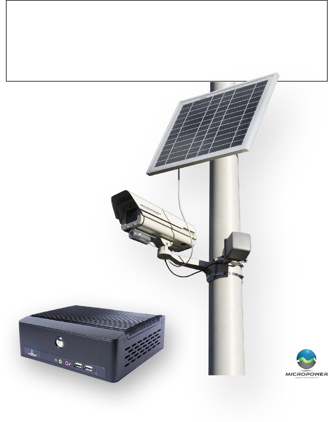
Solveil Solar Powered Camera
Installer Provided Parts and Infrastructure
Solveil Hub
SLV-C30S-1040-IR, SLV-C30S-1040, SLV-C306-1011-IR, SLV-C30S-1011
• Solar Wireless Video Camera/ IP66 Enclosure
(Includes (2) Phillips screws for aaching the bracket to the camera housing)
• Camera Mounng Arm
(Including aachment and bracket screw ulized to adjust the camera posion and angle)
• One Direconal Antenna (2.4GHz)
(Includes bracket with washers and screws and antenna cable)
• One External Solar Panel (Includes bracket and mounng screws) Solar panel size will vary depending on the
geographic region the camera is installed.
• Antenna Bracket Assembly
• Installer should supply addional screws or stainless steel worm drive bands “hose clamps” in appropriate
size(s) for mounng the various camera system components to a pole.
The installer will need to provide the parts required to physically mount the solar panel, camera, and antenna
assembly to the desired mounng surface. This may include screws, stainless steel hose clamps / straps, masts,
wire es, etc. As needed for a given installaon situaon.
The installer will also need to have a means to access the desired mounng locaon, as well as the tools as needed
to complete the installaon job. Such as a 10mm & 8mm socket, baery powered drill, screw driver, zip es, 2 sets
of pliers, ladder / powered li, etc.
The hub will require reliable 110V AC power, a climate controlled (or semi-climate controlled) dry environment to
mount or place the receiver, and a means for the antenna cable to access the outside of the structure such that
clear line of sight can be established between the hub antenna(s) and the camera antenna(s). The hub will also
require an IP network connecon (Ethernet) in order for the video streams to be accessible. The hub may also be
powered by a 12VDC source, or via a PoE (803.3at) splier capable of supplying at least 15W of power.
(SLV-H20HA)
• Solveil Hub, Including power supply, mounng hardware, antenna cable, connecon adapters and 15’ long
antenna cable (longer cables may be purchased from MicroPower)
• One Direconal Antenna (2.4GHz), Including bracket with washers, etc.
Default Hub IP Address: 192.168.0.100
Default Hub Login: kevin
Default Hub Pass: kevin
5
MicroPower System Overview
How It Works
MicroPower Technologies has developed an extreme, low power, camera and radio architecture that has been
designed from the ground up to be solar powered. When combined with the MicroPower Trust Linx™ wireless
protocol, reliable long-range digital CCTV video can be transmied while consuming less than 10% of the electrical
power that most convenonal wireless IP cameras consume. Ulizing this patented technology, the MicroPower
wireless video cameras can remain transming and fully operaonal for up to ve days in complete darkness,
relying on only the internal rechargeable baeries. Overcoming most weather condions without any performance
loss or need for maintenance. Addionally, the TrustLinx radio technology reliably coexists with other wireless
technologies such as tradional Wi-Fi (802.11b/g/a/n), while reliably transming high-quality digital video to
distances up to 1/2 mile with the standard antennas.
MicroPower’s technology eliminates the need for trenching and/or long cable runs to remote outdoor cameras,
thus signicantly reducing installaon me and labor costs, allowing cost eecve remote video coverage in
locaons where surveillance was never before possible.
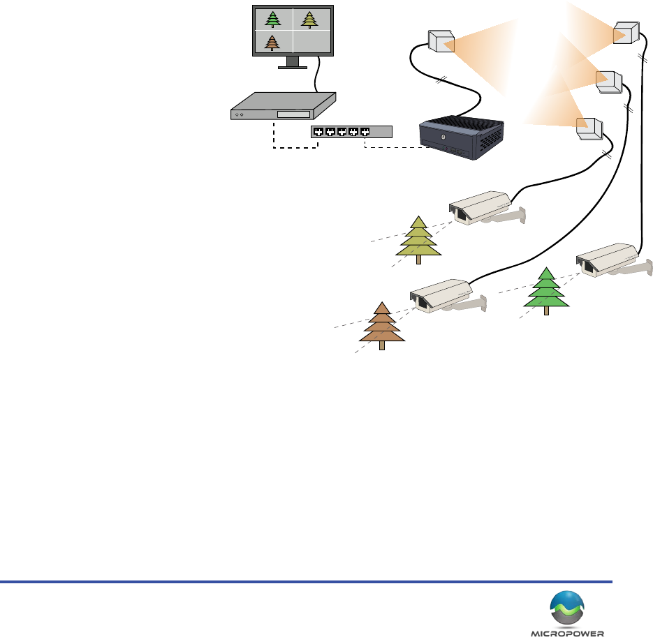
A maximum of (4) wireless cameras
may be simultaneously linked to a
single hub (Cameras must be within
range, and have good Line of Sight
between the antennas). A total of
30fps are available to be shared
between all the cameras connected
to a given hub.
The Solveil Hub acts as the only
data connecon point to which a
Video Management System (VMS),
Network Video Recorder (NVR) or Hybrid Digital
Video Recorder (DVR) can communicate.
Just like any convenonal IP CCTV camera, the
standard Ethernet TCP/IP video data from the
hub may be transmied through virtually any
convenonal broadband or wired network technology
such as LAN, DSL modem, cable modem, cellular
modem, mesh network, wireless back-haul etc. to
reach your chosen VMS soluon.
The standard h.264 video streams generated by the
hub are available to the VMS via RTSP.
The MicroPower Solveil System operates on 2.4GHz, but is not using convenonal WiFi communicaons (though it
does use the same frequencies, and channel number designaons). The camera system uses two bands within a
selected 2.4GHz channel. First is the “Payload Band” also referred to as “Wide Band”. It will occupy channels 2, 6,
or 11 on the 2.4GHz spectrum. The wide band communicaon is used to deliver the video payload one-way, from
the camera to the hub. Next, the hub species a “Narrow Band” or “Command Band”, which is a small subdivision
of the channel used for the wide band communicaons. This is where the command level communicaons occur
between the hub and the camera(s). These terms “Wide Band” and “Narrow Band” are used throughout this
document.
Ethernet Switch
VMS Server
VMS Display Monitor
Antennas
Antennas
Antennas
Camera
Camera
Camera
MiniHub
MicroPower Technologies
1-877-536-0128 | micropower.com
6
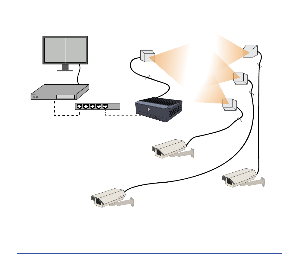
Hub Connecon Method
RTSP Streaming
The hub communicates to your VMS using h.264 RTSP streaming. In order to operate correctly, an IP address will
be needed for the hub, plus, and addional IP address will be ulized to represent each camera on the hub.
To access the individual video streams, one will use the unique IP of the camera, while the trailing URL remains
consistent. (See illustraon on right)
In the event of a camera outage, the IP address represenng that camera can be disabled aer a user dened
period of me. This allows a VMS system to detect the camera loss (IP is no longer accessible, and can no longer be
pinged) and send the appropriate alerts or scripted acons.
Note that the individual cameras are never actually a part of a given computer network. The IP addresses are
operated and maintained 100% inside the hub, and only represent the camera video streams.
NOTE: When segn up a camera, you should enter the IP address of each Solveil camera at that me. Do not
leave the eld blank or use the same IP address that is assigned to the hub.
Ethernet Switch
VMS Server
VMS Display Monitor
Antennas
Antennas
Antennas
MiniHub
rtsp://192.168.1.101:554/h264/1/media.amp/trackID=1
http://192.168.0.100
http://192.168.0.105
rtsp://192.168.1.102:554/h264/1/media.amp/trackID=1
rtsp://192.168.1.103:554/h264/1/media.amp/trackID=1
7
Geng Started - First Steps
Site Survey
A well thought out plan for the locaon of the hub, hub antenna(s) and camera(s) is a crucial step to ensuring that
the enre system will provide reliable long-term service, and integrate eecvely with a new or preexisng video
management system.
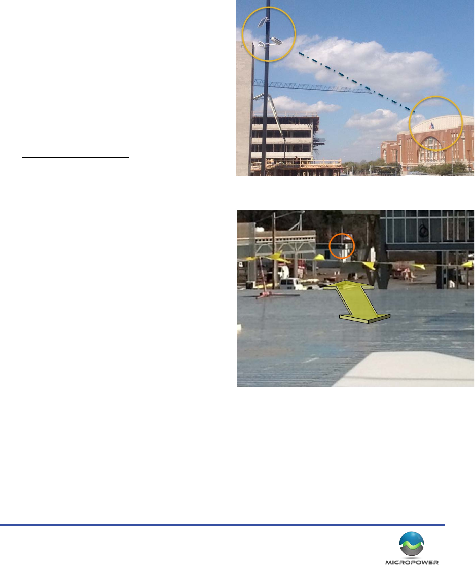
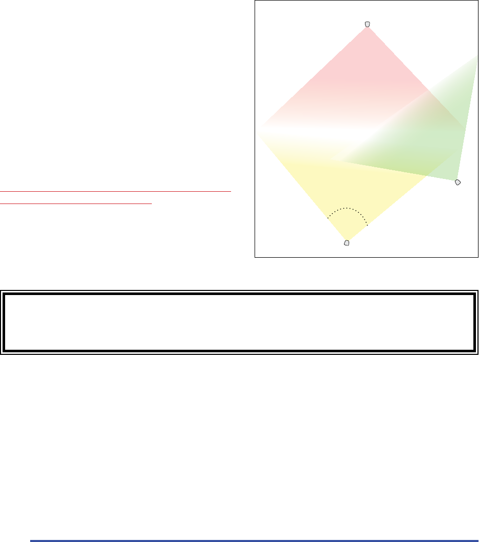
RF Consideraons
Radio Frequency Line of Sight (RFLoS) diers from
visual line of sight. When dealing with RF, if you
imagine a laser beam between the two antennas, this
needs to be unobstructed, plus an addional space
around the beam. In most situaons, the addional
clearance needed is “football” shaped, and (at 1/2mile)
will ideally be at least 13 feet in diameter around at
the center point between the antennas. (100yrds
needs about 4.5’ min. clearance) This accommodates
the system’s Fresnel Zone requirements.
With unobstructed line-of-sight between the hub
and camera antennas, the standard Solveil system
will reliably transmit video up to 1/2 mile. Obstacles
such as trees, buildings, fences, and other objects
will greatly impact wireless performance in terms of
maximum transmission distance, data rate speeds, and
reliability. While a wall or tree may not cause any
signicant performance impact at very short ranges
(under 20yrds), it will likely completely block a signal
at longer distances. Addionally, for reliable extremely
short-range performance, the minimum distance
between the hub antenna and the Camera antenna
should be 25 feet with the RF output level set to the
lowest seng unless signal aenuators are installed.
It is also a good idea whenever possible to have an idea
of the ambient RF trac with regard to the installaon
locaon. Whenever possible, congested channels
should be avoided in favor of less ulized frequencies.
Use of RF scanning tools, such as the MetaGeek
“WiSpy” device, are strongly encouraged.
If obstrucons are present, the distance between the
antennas is too great, or area ambient RF condions too crowded, then the video streams may fail to establish a
link, experience dropouts and/or operate at a reduced frame rate.
Example of good, open RF line of sight.
Example of very challenging / poor RF line of site condions. Note the metal
surface low, and the buildings on the le and right side that can aenuate the
RF signal.
MicroPower Technologies
1-877-536-0128 | micropower.com
8
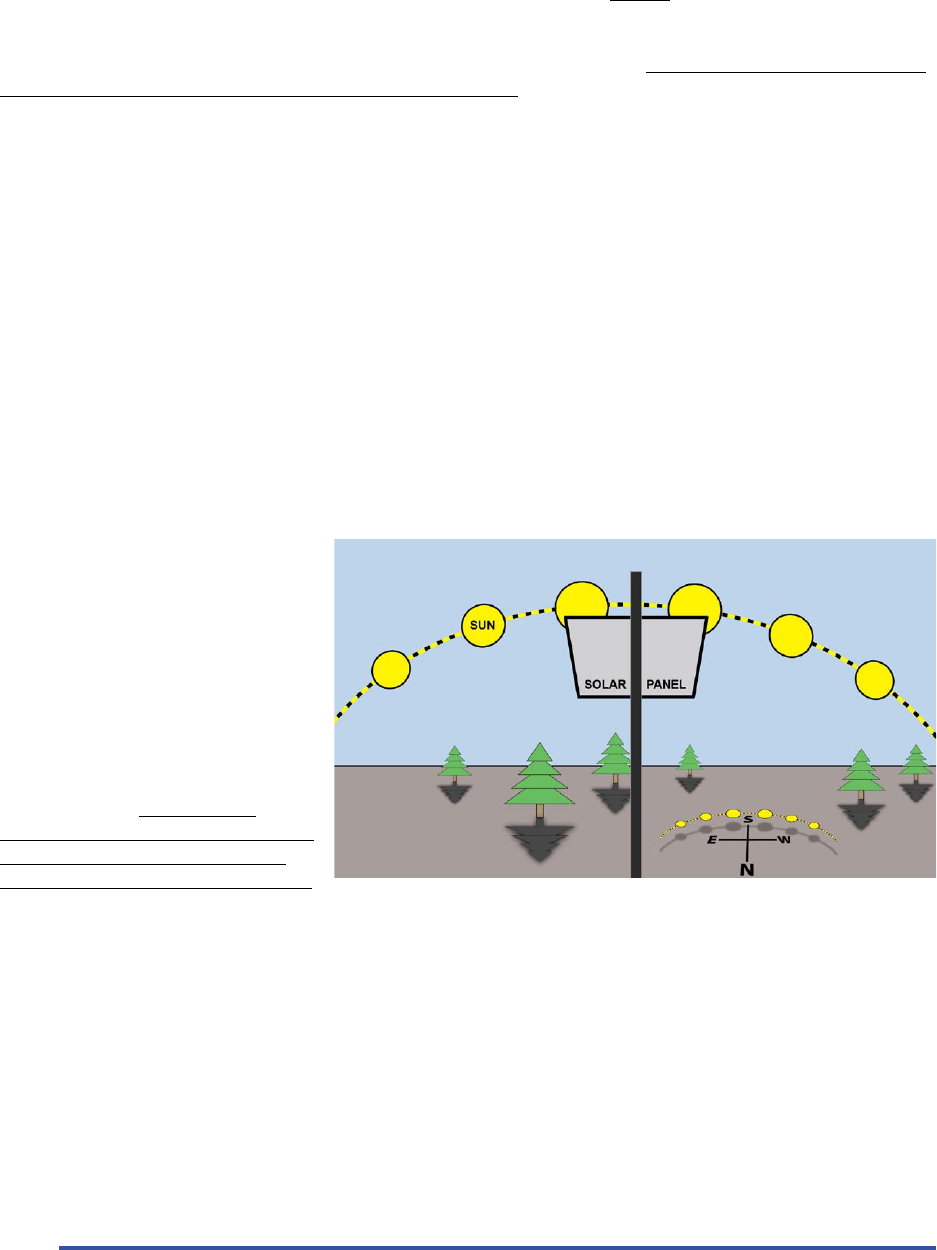
Solar Consideraons
Since the wireless camera is powered by solar energy, the crical impact of DIRECT sun direcon and shadows on
the solar panel cannot be overstated.
In the Northern hemisphere, when selecng a locaon for the wireless camera, the solar panel must be mounted
on the SOUTH side of a pole or structure, and be facing SOUTH.
In the Southern Hemisphere (below the equator), the direconal consideraons will be reversed.
The solar panels should also be installed at an opmum angle to capture the maximum amount of solar energy
possible. In general, the Southern US should angle the panel about 35-45 degrees from the pole, Mid US about 25
- 35 degrees from the pole, and with the Northern US / Canada, 10 - 20 degrees from the pole (solar glass almost
enrely facing the horizon)
Areas with insucient direct sunlight will eventually result in camera outages, though it may take from 5 days to
several weeks to occur. Examples of such areas might be:
• Mulple solar panels on a pole, spaced too close together, or with other equipment on the pole creang
shadows on the solar panel glass
• Panels mounted underneath a tree canopy or foliage which does not receive adequate sunlight
• Installaons next to a tall building that cast a shadow over the camera during the day. (Parcularly during the
most important mid-day charging period)
• Solar panel mounted under a roof or roof edge that does not allow enough direct sunlight
Keep in mind that the cameras include
a baery backup system capable
of operang the camera 24 hours a
day, for over ve days in complete
darkness. If the system is receiving
some light, but at levels that are
below the “break even” point, the
operaon me may be potenally
extended for weeks before a camera is
nally no longer capable of remaining
operaonal 24/7. Thus, it is important
to be aware that a camera may
appear to operate ne in poor lighng
condions, when in fact it is slowly
discharging over a long period of me.
As this is a solar powered camera, sucient dayme lighng is absolutely crical to the long-term successful
operaon of the system. Addionally, making sure there are no shadows cast on the panel during the day also
plays a crical role to success. Solar panels, by their nature, are sensive to and negavely impacted by shadows
(even very small ones) on the panel, these shadows may also come from other equipment mounted on a pole, such
as wiring, other solar panels, or mounng hardware. Some of the most common dicules that occur in the eld
can usually be aributed directly to solar panel shadowing.
Note: As an installer, the best way to idenfy the charging rate, baery levels, and signal performance, is to use our
the hub’s built-in HTML interface to determine if the system is performing well or not in a given installaon.

9
What You Will Need
Equipment
Computer / Soware
• Computer: Windows™ 7 or Windows 8 tablet, or small laptop is helpful for focusing.
• A web browser (Firefox, or Chrome work best)
• Oponal: Laptop with wireless internet access (local WiFi or Cellular WiFi) that can be le temporarally
connected to the hub for live performance monitoring via a internet enabled smart phone.
Hand Tools
• Baery Powered Screwdriver or Impact Driver
• 1/4” and 10mm socket wrench (easiest if aached to baery powered driver)
• Zip Ties
• Pliers
• Magnec compass and Protractor (a smart phone with a compass and angle detecon will also work)
Means To Access Camera Locaon and Hub Locaon
• Ladder / Bucket Truck / Manli “cherry picker”
• Safety Harness, etc.
• Roof Access to get the hub antenna outside and elevated to achieve LOS (Line of Sight) to the cameras
Method to Mount the Camera and Hub to Desired Locaon
MicroPower supplies a camera bracket, a solar panel bracket, and an antenna bracket that can be mounted to
a pole. Given the variety of mounng possibilies and locaons, the hardware to aach these brackets to the
desired surfaces are not included. This means the installer will need to supply:
• Screws (oponal to aach hub to wall, and/or camera, antenna and solar panel bracket to pole / surface)
• Stainless Steel hose clamps (to aach solar panel and camera to pole)
• Antenna mast or surface to mount/aach the hub antenna to.
Network Access
The hub is an IP device and will require both power and LAN/Network access in order for the video to stream to
an NVR and/or remote locaon. Generally this is done via a house LAN, but may also be some other method of
network access such as a back haul radio, cellular device, or other IP Ethernet network technology.
VMS (Video Management System)
The hub generally communicates on the LAN to a local NVR (Network Video Recorder) for recording and archiving
of video. The NVR will then typically communicate via the Internet or LAN/WAN for remote viewing and
monitoring. However the actual network conguraon tends to vary greatly from site to site.
The VMS used, needs to be capable of recording a basic RTSP h.264 video streams from the hub in order to be
compable.
A complete list of compable VMS plaorms with integraon instrucons are available on the MicroPower website.
MicroPower Technologies
1-877-536-0128 | micropower.com
10
Hub Installaon
At the center of the MicroPower camera system is the Helios Hub. This is the “brain” of the system that
communicates with the video cameras, and produces the video data streams that the VMS system will record and
display.
Hub Assembly and Installaon
Remove the hub and mounng bracket from the box and locate a suitable place to install. This will typically be in
a network closet, however any locaon that is semi-climate controlled with access to Ethernet networking, power,
and where the antenna cable can be routed outside, will be suitable. Customers have mounted hubs inside drop
le ceilings, HVAC closets, Air vents, and many other locaons depending on the situaon.
It is also possible to power the hub via high power PoE (802.3at)
however doing so requires the use of an 802.3at PoE splier kit
with a and custom power cable (sold separately).
The mounng bracket will aach to the back of the hub, while the
other part will aach to the wall. The hub poron then ‘hangs’ on
the wall bracket, and is secured via the locking screws. (Installer
provides the hardware to aach to the wall). Note that the hub
may also simply be placed on a shelf or at surface, mounng is not
required.
Note: Do not stand on sides or cover the venlaon ports in any way.
The hub locaon should have clearance for the cabling, power brick, network cable, etc. to aach without
making sharp bends. It is parcularly important not to make sharp bends or “kinks” in the main
antenna cable(s) or it can result in signicant RF signal dicules.
Important:
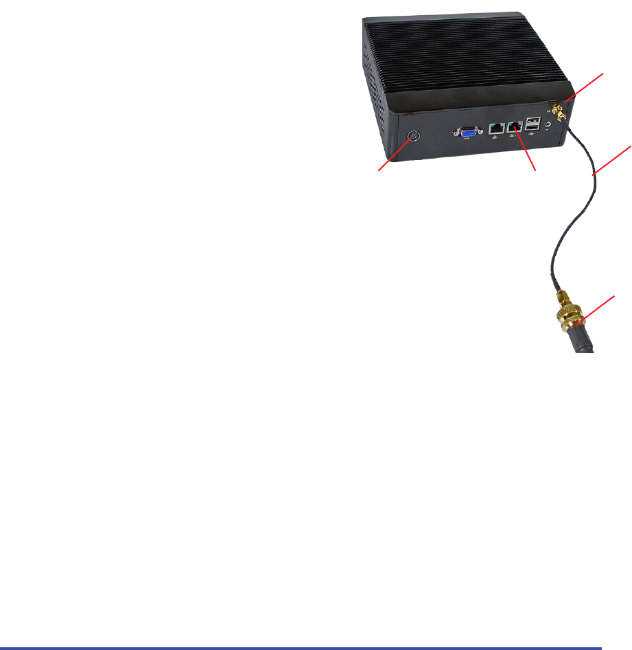
• The antenna will connect via a small black strain relief cable. Please use this to prevent stress
damage to the antenna cable or the SMA antenna port on the hub.
• The Ethernet network port closest to the power plug is acve. The 2nd port is not used, and will
not funcon if connected. (This port is usually covered)
• Do not stand the hub on the narrow side, or block the venlaon ports in any way.
Once the hub is mounted the antenna cable is routed to an exterior locaon on the building, where the antenna
may be mounted to achieve line of sight to the camera antennas. To avoid damaging the fragile connecon cables
between the hub and diplexer, we will normally aach the antenna cable last, aer the hub installaon process has
been completed.
NOTE: Ethernet Port
(2) is NOT used.
Power Port
Antenna Port
Antenna Cable
Stress Relief
Antenna Cable

11
MicroPower Technologies
1-877-536-0128 | micropower.com
12
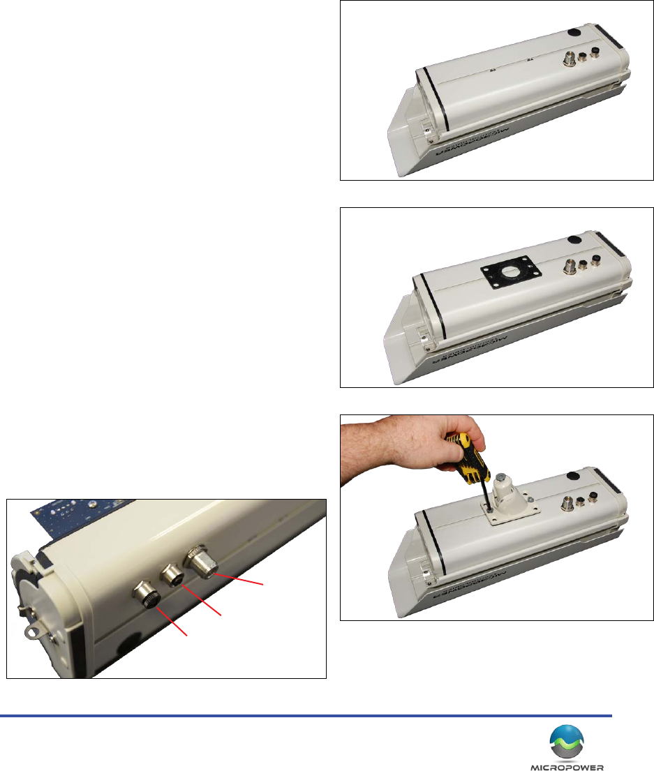
Hub Antenna Assembly and Installaon
The antenna assembles into it’s mounng bracket and may then mount the antenna assembly via straps to a pole,
or via screws to a at surface.
Take care to avoid mounng the antenna directly to a large at metallic surface (such as corrugated n walls) as the
RF reecons from such surfaces can somemes be problemac.
The installer will generally need to provide a mast, or appropriate surface to mount the hub antenna. The installer
also needs to provide the means of aaching the antenna to the desired mounng surface (screws, stainless steel
hose clamps, etc.).
The hub antenna has a eld of view of approximately 90° and should be such that all of the remote cameras are
within the eld of view. If one camera is parcularly farther away than the others, somemes it is helpful to dri
the antenna a bit toward the farther target vs. precisely centering between all the cameras.
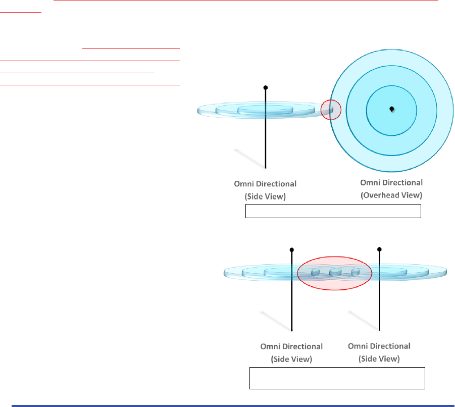
Regardless of how the antenna is mounted, the following must be observed:
• Antennas should always be mounted with the drain holes facing down and the front of the antenna facing
your target. If the drain holes are facing up, upon the rst rainfall the antenna will ll with water and be
damaged.
• All the antennas that are communicang with each other must be mounted in the same orientaon (both
hub and cameras). If the antennas are not
mounted idencally, they will be polarized
o-axis, and thus be prevented from
eecvely communicang with each other.
O-axis antennas, very poor communicaon.
Antennas oriented (polarized) the same, good
communicaon
13
Hub System Setup
Accessing The Hub
Default IP Address
The hub has a default IP address of: 192.168.0.100. To inially communicate with the hub, connect an Ethernet
cable directly from the hub to a laptop or desktop PC. A crossover cable may be required, however most
modern computers have auto-sensing Ethernet ports that make this unnecessary. The hub may also be plugged
directly into an Ethernet switch that your computer is
also connected to. Note that if your network is using
192.168.0.X IP addressing, there may be a device on your
network already using the hub’s default IP, so the hub may
need to be congured o the network rst, prior to being
connected. As usual with IP based devices, you will need
to set your computer to a similar IP address as the hub
(such as 192.168.0.99, or 192.168.0.115), before you will
be able to inially communicate with it. While the hub
can be used in DHCP mode, we strongly suggest manually
conguring a stac IP address.
Conguring the Hub
Changing The Hub IP Address
Once the antennas are connected, and the network cable
is in place, connect the power cord and if the power light
does not illuminate immediately, push the large silver
power buon on the front face of the hub to turn it on. It
will generally require somewhere between 40 seconds to 1
minute before it will be accessible on the network.
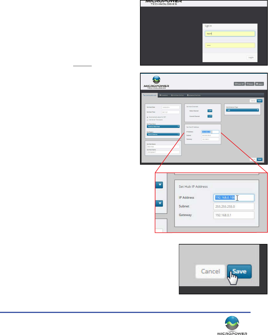
Use a web browser (we recommend “Firefox” or
“Chrome”) to inially log into the hub on the default IP of
hp://192.168.0.100. If the IP sengs on your computer are
correct, and the hub is powered on and running, you should see
the hub’s login screen come up almost immediately.
The login is “kevin” and the password is “kevin”...
On the rst screen you will see the current IP address displayed.
Click on the IP address, subnet, and gateway boxes, and change
them to the desired values. When the IP informaon has been
correctly entered and double checked, click the “save” buon,
and click through any prompts that follow.
If the receiver X needs to reboot, follow the prompts to allow it to do so.
Aer approximately (1) minute, the hub should then be accessible on the
newly assigned IP address.
System Conguraon
MicroPower Technologies
1-877-536-0128 | micropower.com
14
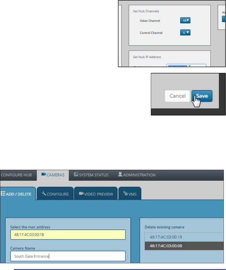
Changing RF Channels
On the Solveil system, a hub will always default to the same radio channel (just as there is a default IP address)
thus channel selecon is very important, parcularly if there are mulple hub systems operang in the same
general area. Never run two Solveil systems on the same channels, within range of each other, or there will very
likely be signicant loss of system performance.
Video Channel: Represents the 2.4GHz channel that the video is transmied on, from the camera to the hub.
There are (3) choices, 2, 6, and 11. Try to choose a channel
that has the least amount of trac present.
Control Channel: Represents which small secon of the
video channel is also used for the camera to communicate
with the hub, via 2-way communicaon.
Be sure to click “Save” when you have completed making
your channel selecons.
Security Note: The camera system does not communicate
using any form of WiFi, and that the video signals and
communicaon signals do not contain any IP addresses,
or network data. This provides an enhanced layer of security because the
system never transmits any network related data that could compromise
the security of the host network. All networking tasks, are handled
internally in the hub, and transmied via the ethernet port, never via the
wireless network.
Adding Cameras
On MicroPower systems, individual cameras are never actually part of your computer network. Cameras are
idened to the hub by the MAC address that is assigned to the camera. This MAC address can be located on a
scker that can be found on the exterior and the interior of the camera. Generally they will resemble the following
structure: “48:17:4C:02:xx:xx” (“xx:xx” will vary from camera to camera). Make a note of all of the camera MAC
addresses in a given system and where those cameras are installed.
1. When logged into the hub click on the “Cameras” tab, and then on “Add/Delete”, here you will see a list of
cameras that are currently added to the hub (click the “refresh” buon to populate the list). The list should be
blank if you are seng up a hub for the rst me. If the hub is new, and you see a camera already added, click the
15
box next to it, and click “Remove”, then reboot the hub. On rare occasions, a test camera remains installed from
the tesng done during manufacturing.
2. To add a camera type the camera MAC address into the box provided. (If your camera is powered on, you may
see it indicated as a choice in a pull down menu)
3. Select the camera or enter the camera MAC address into the box, name the camera, and click “Save”.
4. Click the “refresh” buon every few seconds unl the new MAC address appears in the list of acve cameras.
5. Repeat the process for addional cameras.
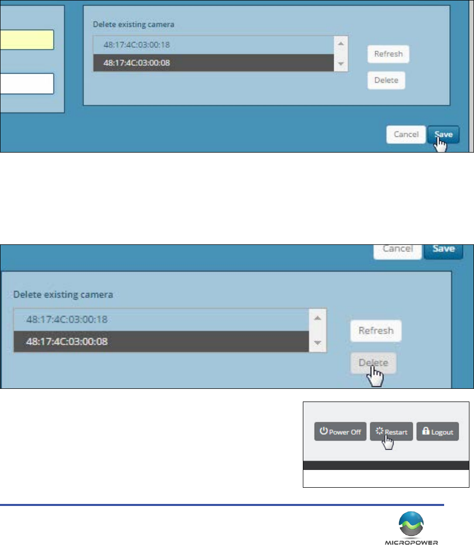
4. When you have added all the cameras to the hub (up to a maximum of 4), reboot the hub by clicking on the
“Restart” buon at the top of the screen, and following any prompts.
Removing Cameras
In some circumstance (such as moving a camera to another locaon on to a dierent hub, replacing a camera,
etc.…) you may need to “remove” a camera. To remove a camera from a hub, simply click on the camera you wish
to remove, and click on the “Delete” buon. The camera will be removed from the system’s database, and may
then be replaced, or moved to another hub.
Aer successfully removing any cameras, you should reboot the hub by clickign on the “restart” buon found at
the top of the screen.
MicroPower Technologies
1-877-536-0128 | micropower.com
16
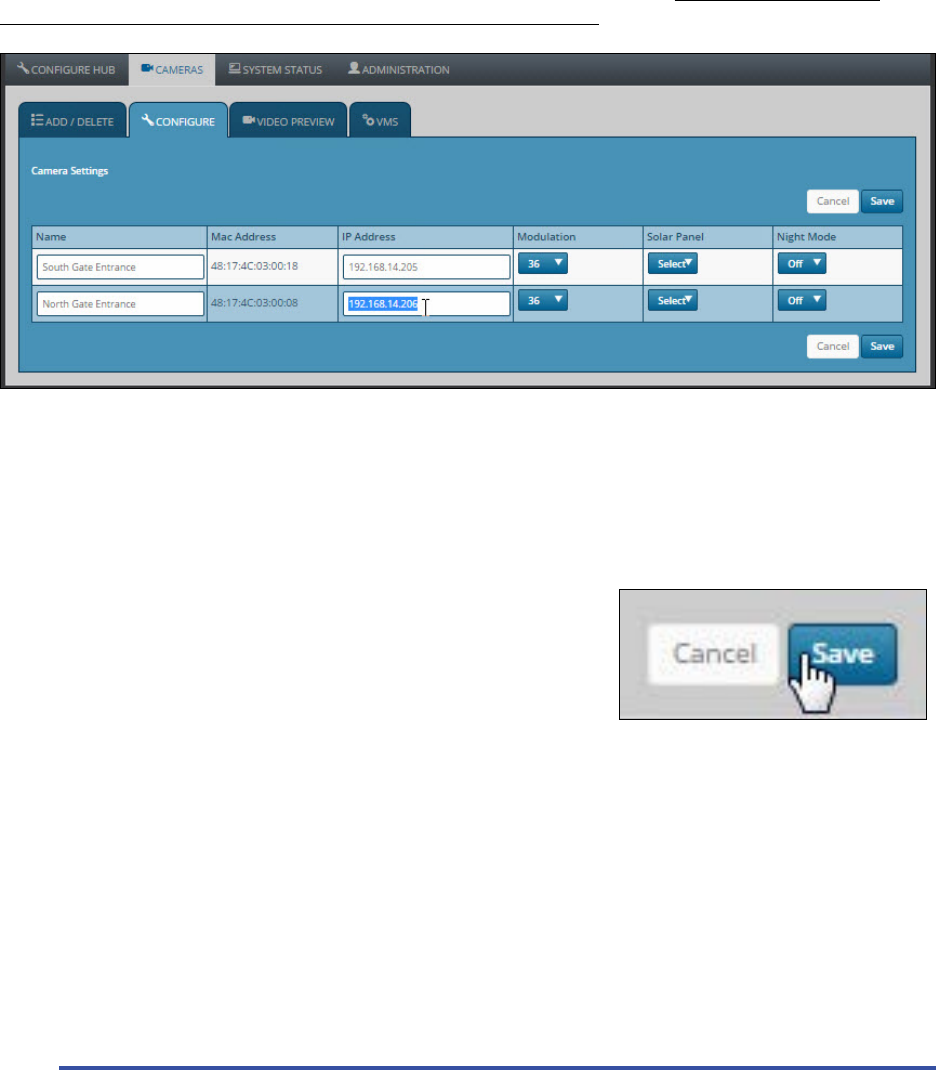
Camera Conguraon
IP Address: Here you can enter the IP address that will be used to represent a specic camera. A unique IP address
is required here, do not enter the same IP as the hub.
Modulaon: This is the speed of the communicaon that video is sent from the cameras to the hub. Generally
installers keep this seng consistent for all the cameras on a hub. If the cameras are relavely close, and have a
good signal strength (-55dB to -65dB), then 36 is ne.
If the cameras are at a distance, and/or have a weaker signal level (-66dB to -70dB) Then most installers will
change this seng to “24” in order to achieve a more reliable video link.
Solar Panel: This seng should be changed to reect the size of the solar panel that was shipped with your
camera. Dierent size solar panels are used for dierent regions of the world, depending on the amount of
sunlight they get on average each year. Seng this value to match your panel size, helps the system to accurately
esmate the power levels and capacity of a camera.
Night Mode: This seng is relevant if your camera is equipped with IR illuminaon. “Auto” will allow the camera
to automacally switch to night mode in low light situaons. “O” forces the camera to remain in day mode 24/7,
and “On” locks the camera into night mode. “On” is provided for tesng,
and for certain very specic applicaons such as License Plate Recognion
(LPR) when IR ltering. Generally an installer will always set this to “Auto”.
Be sure to click “Save” to preserve your seng changes
Camera Sengs
Frame Rate, Bandwidth, Nightmode Transion, IR Brightness, Video Preview
Clicking on the “Video Preview” tab will reveal a variety of sengs that are specic to each camera.
Frame Rate: This value may be set to determine the number of frames a camera sends per second. As of the
publicaon of this document, each hub is capable of handling a system-wide total of 30fps, divided up between
the cameras. It should also be noted that the energy consumpon of a camera rises with it’s framerate. Cameras
installed in areas with poor sunlight may nd advantage to keeping the frame rate low. For most security
applicaons in areas such as parking lots, 5fps is quite sucient. However some analyc packages, or just personal
preference may dictate that the frame rate be set higher.
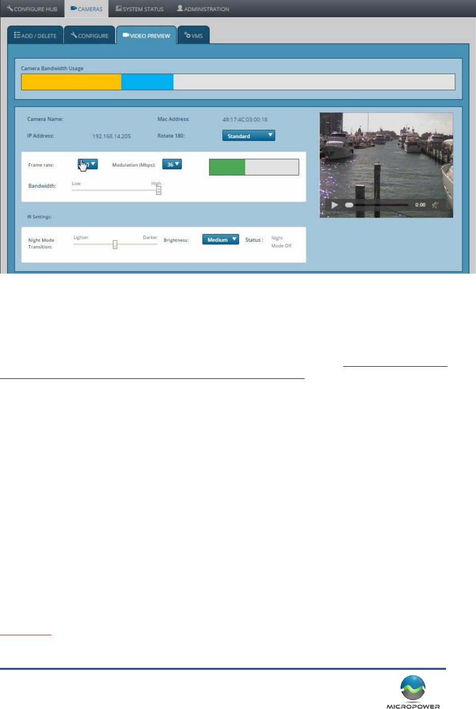
17
Modulaon: (This is the exact same seng that was on the previous tab. It’s inclusion here is just as a
convenience.) Modulaon is the speed of the communicaon that video is sent from the cameras to the hub.
Generally installers keep this seng consistent for all the cameras on a hub. If the cameras are relavely close, and
have a good signal strength (-55dB to -65dB), then 36 is ne.
If the cameras are at a distance, and/or have a weaker signal level (-66dB to -70dB) Then most installers will
change this seng to “24” in order to achieve a more reliable video link.
Bandwidth: This value represents the amount of compression that is applied to the video stream. High bandwidth
will produce beer quality video, but larger le sizes.
Bandwidth Usage Graph: This graph represents the amount of available bandwidth that the camera is consuming
at the current sengs
Retransmission Graph: The green graph to the right of the camera sengs, indicates how hard the hub is having
to work to retrieve video from the camera. This is a good indicaon of RF noise, and interference.
Night Mode Transion: This seng inuences at what level of brightness that the camera will shi into IR mode.
(the default seng is generally best)
Brightness: The power level of the IR illuminator. This may be adjusted as needed to provide the best nighme
video. (Nearby reecve objects may require the level be lowered, whereas far away targets may need more
output power)
Video Preview Box: Push the “play” icon on the video window to watch a live feed from the camera. This is useful
for focusing, and evaluang your seng changes on the resulng video.
IMPORTANT: The sengs on this page are saved and sent to the camera immediately. There is no “save” buon
on this page. Changing the modulaon rate, may result in the camera briey dropping the wireless link while the
mode change goes into eect.
Note: The above digram is from a (1) camera system. More or less cameras will display (scroll down) depending on your installaon.
MicroPower Technologies
1-877-536-0128 | micropower.com
18
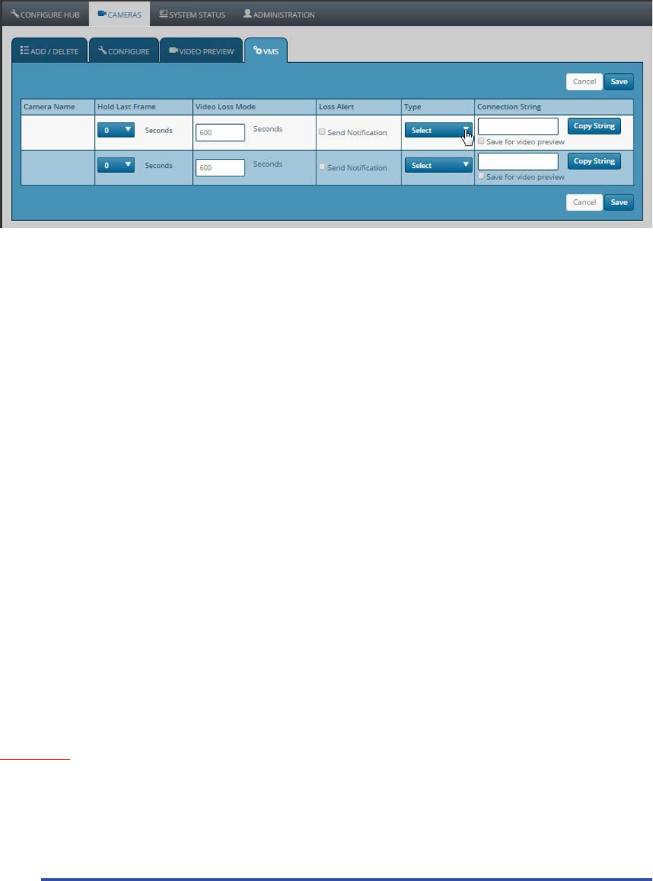
VMS Tab
The VMS Tab contains sengs that pertain to how the camera system interacts with your NVR / VMS.
Hold Last Frame: In the event of a momentary camera outage, the sengs here determine how long the video
image will remain frozen before changing to a black screen. This seng is very useful to mask small camera
glitches that may occur in a very heavily congested RF enviornment. Parcularly if the camera video may be
displayed in a publically viewable locaon.
Video Loss Mode: The user inputs a value in this locaon that determines how long a camera will be allowed to
remain oine, before the IP address associated with that camera is deacvated. This provides a means of allowing
your VMS/NVR system to detect that a camera has gone oine. (by producing the same condions that would be
present as if a convenonal IP camera had been powered down, or disconnected) Note: This feature will only be
acve if the check box for “Send Nocaon” is selcted in the next column.
Loss Alert: Check the box next to “Send Nocaon” for a specic camera, to enable the ability for your VMS to
detect when a camera has gone oine for an extended period of me. (See “Video Loss Mode” above)
Type: Select the desired type of video stream you woudl like to access from a parcular camera. Making a
selecon here will populate the “Connecon String” box to the right, with the proper connecon informaon
that your VMS will need in order to communicate with the cameras via RTSP. This provides an easy way to choose
your desired compression method, and to obtain the informaon that will be needed to set up your VMS to
communicate with that camera.
Connecon String: The connecon informaon that is needed in order for your VMS to communicate with this
camera, will ll in here, depending on your selecon under “Type”. This connecon informaon may be entered
into a video player such as VLC to view the video streams as well.
Copy String: Copies the connecon string to the computer clipboard, so you can easily paste it into your VMS or
video player.
IMPORTANT: Be sure to click “Save” on this page aer making any changes that you want to be preserved,
alternavely if you made changes you do not want to keep, simply click “Cancel”, and the former values for these
sengs will return.
Note: The above digram is from a (2) camera system. More or less cameras will display (scroll down) depending on your installaon.
19
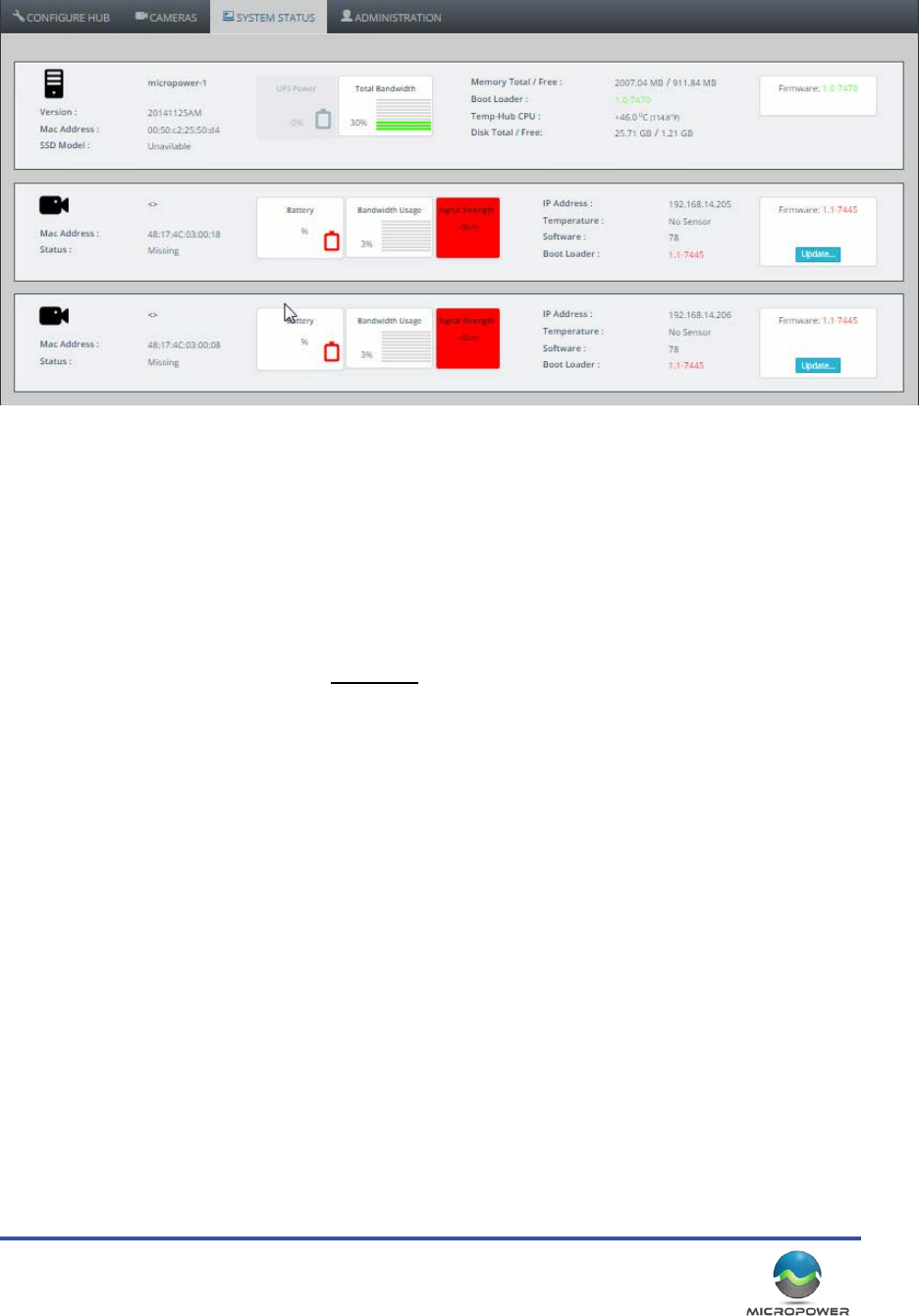
System Status Tab
The System Status Tab is primarily ulized to provide valuable system status informaon to the installer.
System Informaon: The rst row contains informaon about the status and health of the hub. This includes a
graph showing temperature, disk space, rmware version, etc.
Camera Informaon: These rows provide valuable performance informaon regarding the specic camera
indicated. Most importantly, the baery level, Bandwidth usage, and Signal Strength.
Desired Signal Strength Levels: For best performance, we nd that the signal strengths should indicate at least
-70dB or stronger. (-60dB is considerably STRONGER than -70dB, ‘lower’ numbers are beer)
Firmware Update: In the event that there is a rmware update available for your camera, it will be indicated
here. Clicking the buon will push the update out to the camera via the wireless link. (You do not have to visit the
camera in person) Please call MicroPower Technologies with any quesons prior to updang your cameras.
Note: The above digram is from a (2) camera system. More or less cameras will display (scroll down) depending on your installaon.
MicroPower Technologies
1-877-536-0128 | micropower.com
20
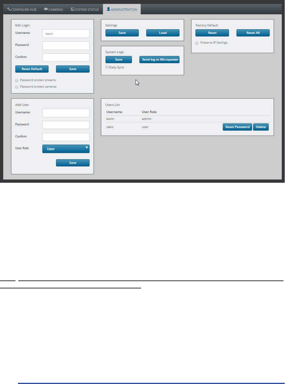
System Administraon
Changing The Login and User Accounts, Saving Conguraons, Factory Default
Edit Login: This secon allows the operator to password protect the video streams and camera sengs. (Note:
password protecng the video streams may compromise VMS compability, depending on the make and model)
Add User: Adds new users to the system, allowing the administrator to secure the box, and allow specic intended
people access o make changes, or see the sengs.
Sengs: Allows the operator to save the current hub conguraon to their local computer, or, to load a saved
conguraon le to a hub. This can be used to restore a conguraon to a hub that has been factory defaulted.
Factory Default: Clears the sengs in a hub, and returns it to the factory default sengs.
NOTE: Remote users should be certain to check the “preserve IP Sengs” opon, so that aer the factory default,
the programmed IP address will sll remain in the system. Otherwise, the hub will return to it’s default IP address
of 192.168.0.100, and potenally become inaccessible from a remote connecon.
System Logs: This feature will save the system logs that are stored in the hub. The log data contains informaon
about the performance of the hub, signal strengths, charge levels, etc. (No images or video clips are stored or
transmied) This informaon is useful to provide to MicroPower for trouble shoong purposes.
System Logs Daily Sync: If the hub has internet access, checking this box will instruct the system to upload the log
data nightly to the MicroPower oces. This is useful in the event of a problem, MPT will already have the previous
nights logs on hand for review and analysis. “Send Log to MicroPower” will cause the system to immediately being
uploading the log data to the MPT oces for analysis and troubleshoong.
21
Camera Kit Assembly & Installaon
Next we will cover how the cameras and camera components are assembled and installed. Some installers nd it
easier to do the assembly process on mulple cameras at the same me, and bring the cameras to the pole “ready
to bolt on”. Others prefer to assemble the parts at each locaon. Regardless the camera / solar panel / antenna
assembly process should be done on the ground, prior to actually mounng any of the equipment. As much as
possible this guide is moving in chronological order, so we will rst cover the assembly of the parts, and then
address the mounng / installaon process.
System Assembly
Camera Assembly
The camera itself only needs to have the camera swivel
bracket aached to it.
1. Remove the camera bracket from the packaging, and
remove the pivong mount from the main bracket,
by removing the single screw that holds it in place.
Replace the screw back into the pivong bracket to
prevent it from being lost.
2. Place the rubber bracket pad on the camera housing,
and line up the capve screws with the holes.
3. Next, mount the bracket hinge on the underside of
the camera by using the small/shallow Phillips screws
included in a small plasc bag that may be found in
the packaging.
4. Before ghtening the bracket to the camera housing,
slide it up and down the housing unl you can li the
camera by the bracket, and nd that it is balanced. A
balanced camera will make the later mounng process
much easier.
5. If your camera is equipped with an IR illuminator, you
can plug it into one of the two power sockets at this
me. The other power socket will be used by the solar
panel input.
Antenna
Connecon
Solar Panel
Connecon
IR Illuminator or
Supplamental
Solar Panel
Connecon
MicroPower Technologies
1-877-536-0128 | micropower.com
22
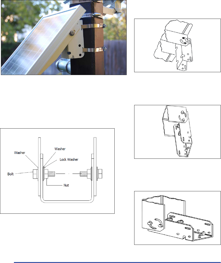
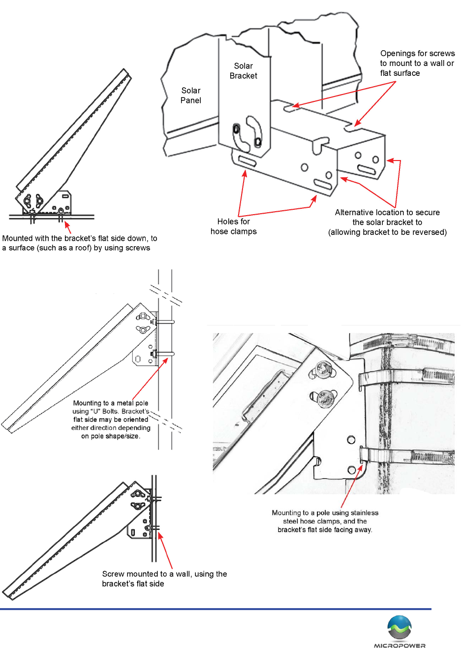
Solar Panel Assembly
The solar panel bracket is extremely versale, and is assembled based upon the mounng surface that it will be
aached to. The “C” shaped bracket can be bolted to the solar panel with the at side facing out (for bolng/
screwing to smooth surfaces), or with the edges of the bracket facing outward (for mounng using straps/hose
clamps to poles). The panel may be mounted to poles, walls, or even inverted and mounted to rooops or ledges.
(See images).
Bracket congured for mounng to a round or square pole by
use of hose clamps / straps. (straps through the slots in bracket)
Assembly of the bracket, and the arrangement of the nuts, bolts, and washers.
Bracket congured for mounng to a at surface such as a wall,
by use of screws or bolts
Solar bracket congured for mounng down, to a at surface
such as rooop or ledge with the solar panel facing upward.
Solar panel mounted to a pole using stainless steel hose clamps that are passed through the
slots in the bracket. This allows for a quick, non-permanent installaon that may be easily
relocated, without damaging the mounng surface.
23
Solar Bracket Mounng Conguraons

MicroPower Technologies
1-877-536-0128 | micropower.com
24
25
Camera System Installaon / Mounng
The order of equipment on the pole may vary from installaon to installaon. Generally the solar panel will be
on top, followed by the antenna, with the camera on the boom. This arrangement generally provides the best
unobstructed light for the panel, however there are excepons. For example if your mounng pole has a large
light on top that will cast a shadow on the panel, it might be wise to move it lower down the pole, or, if there are
tall obstrucons that must be cleared and the antenna must be placed much higher up the pole than the other
equipment. For the purposes of this document however, we will start at the top with the solar panel, and move
our way down the pole.
If the installer has any quesons or concerns, feel free to snap some pictures, and call into MicroPower support for
advice, we are always happy to assist. (877-536-0128)
Solar Panel Mounng
A solar panel is included with the camera which oers complete exibility with the placement of the camera, and
enables reliable operaon in installaon locaons that may have lower light levels, such as northern climates
where snow and ice may typically impact the long-term operaon of solar powered devices. The solar panel
connects to the camera very easily, and may be
secured to a variety of dierent surfaces by a very
simple, extremely versale mounng bracket.
How to Mount the Auxiliary Solar Panel:
The solar panel mounng bracket is extremely
versale, and is designed to be mounted to a pole
with stainless steel hose clamps, “U” bolts, or
screws to rmly secure the panel to the desired
mounng surface.
Always be sure that the panel is rmly secured
against weather events such as high winds, ice, snow, etc. Depending on your parcular conguraon, the installer
will need to purchase the appropriate hardware to aach the bracket to the desired mounng surface.
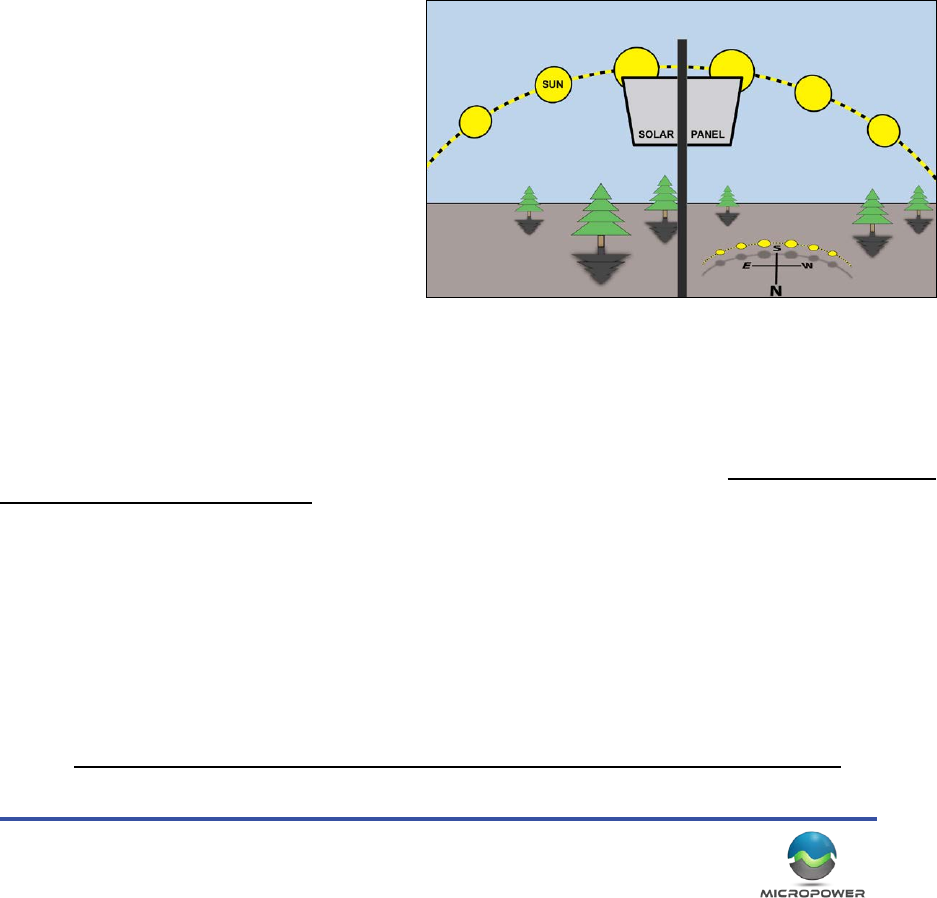
What Direcon to Mount the Solar Panel:
For mounng locaons in the Northern Hemisphere (United States, Mexico, Canada, etc.) The solar panel MUST be
mounted with the glass facing SOUTH, and angled such that it will capture the most winter sun possible during the
daylight hours. The farther North the system is installed, the lower toward the horizon the glass panel should be
angled, consistent with the posion of the sun during the weaker, winter solar energy.
In climates where snow and ice are a factor will also need to angle the panel more sharply, such that snow will not
tend to accumulate on the panel glass. Addionally, it is very important that care is taken to ensure that objects
such as trees, ulity poles, buildings, and most especially the other equipment on the pole (antenna, camera, etc.)
do not create any shadows on any of the solar panels in the system.
Note: The baery ships from the factory at about 40% capacity. During storage and shipment, the baery will
be (and always should be) unplugged from the camera, and will need to be connected in order to power on the
camera. When the camera is not in use, and stored out of sunlight, the baery should be disconnected.
MicroPower Technologies
1-877-536-0128 | micropower.com
26
Antenna Mounng
The direconal antenna should be mounted as the scker indicates on the back of the antenna, double checking
that the drain holes are releasing any water toward the ground. This antenna arrangement polarizes them to
a horizontal plane, which has the benit of excluding a lot of the ambient RF noise that emites from the more
common vercally posioned antennas. It is crical that all the antennas are oriented THE SAME WAY in a given
system, or the noise exclusion menoned previously, will work to ensure the camera can not communicate to the
hub.
Each camera should have one antenna, while each hub
may have one or two antennas depending on the locaon
of the cameras in the eld. Note that is more than one
antenna is being used on a hub, then the maximum
transmission range will be reduced due to the usage of a
signal splier.
** NOTE: THE ANTENNAS HAVE DRAIN HOLES TO RELEASE
ANY ACCUMULATED MOISTURE. THE DRAINS HOLE MUST
BE FACING THE GROUND WHEN MOUNTING **
The direconal antennas when placed at have an
approximate 90 degree eld of view. The camera antennas
should be posioned poinng toward the hub, within the
“cone” of the antenna’s eld of view, for the system to
properly communicate.
(Note that the camera’s antennas should point only to
the hub antenna, not at each other).
The direconal antennas will need to be mounted to the
desired locaon, using hardware supplied by the installer.
Typically this would be done via stainless steel hose
clamps, “U” bolts, or some other clamping mechanism.
Antenna
Camera 1
Antenna
Camera 2
Antenna
Network Receiver
90°
The antenna included in both the camera and receiver hub kit is an 8dBi 50 Ohm direconal
antenna with about a 90° Field of View. It should be mounted and oriented as the scker
on the back indicates, with the plasc front facing your desired target.
27
Camera Mounng
During the assembly process, you’ve already aached the rotang poron of the camera bracket to the camera
housing. This leaves the lightweight camera arm bracket to be easily aached to the desired mounng surface.
1. Use the appropriate hardware to mount the bracket to your desired surface. This may require stainless
steel hose clamps (easiest and quickest, parcularly for large poles), screws (good for at wood surfaces), or
perhaps stainless steel “U” bolts (good for narrow gauge masts).
2. Once the camera arm bracket has been secured to your desired mounng surface, then place the
camera+rotang poron of the mount, onto the camera arm bracket. If you arranged the movable bracket
such that the camera was balanced, it should be very easy to hold the camera in place on the arm bracket,
while you aach the single screw to secure the enre assembly together.
3. Now you can adjust the posion of the camera, and connect the solar power cable and the antenna cable.
4. Once you have the antenna cable and solar power cable aached, you may then power on the camera by
connecng the baery plug inside the camera. IR enabled cameras will have (2) baery plugs that must be
connected (or disconnected to power o the camera) (see next page)
5. Be sure to ghtly secure the arm bracket screw, thus locking the camera in place. It is easy to forget to secure
it ghtly, leaving the camera vulnurable to unintended movement or potenally falling during high winds.
The solar panel should be posioned above the camera, or,
arranged such that so no shadows are created on the panel
surface. (Even small shadows will dramacally decrease
the solar panel eeciency)
MicroPower Technologies
1-877-536-0128 | micropower.com
28
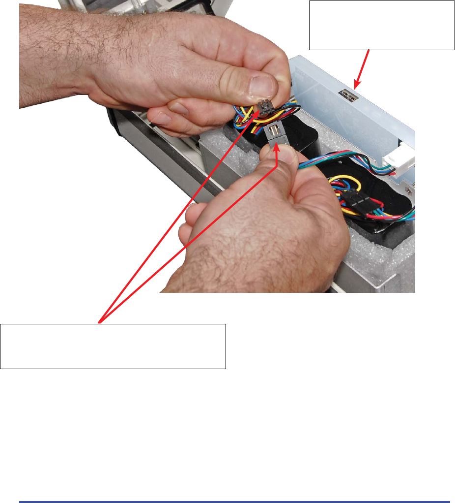
Powering On The Camera
Once you have the antenna cable and solar power cable aached, you may then power on the camera by
connecng the baery plug inside the camera. IR enabled cameras will have (2) baery plugs that must be
connected (or disconnected to power o the camera)
Baery cables connect together to power on the camera.
• Standard Non-IR cameras have (1) power connector.
• Cameras equipped with IR Illuminators will have (2) power connectors,
both of which must be connected for reliable long-term operaon.
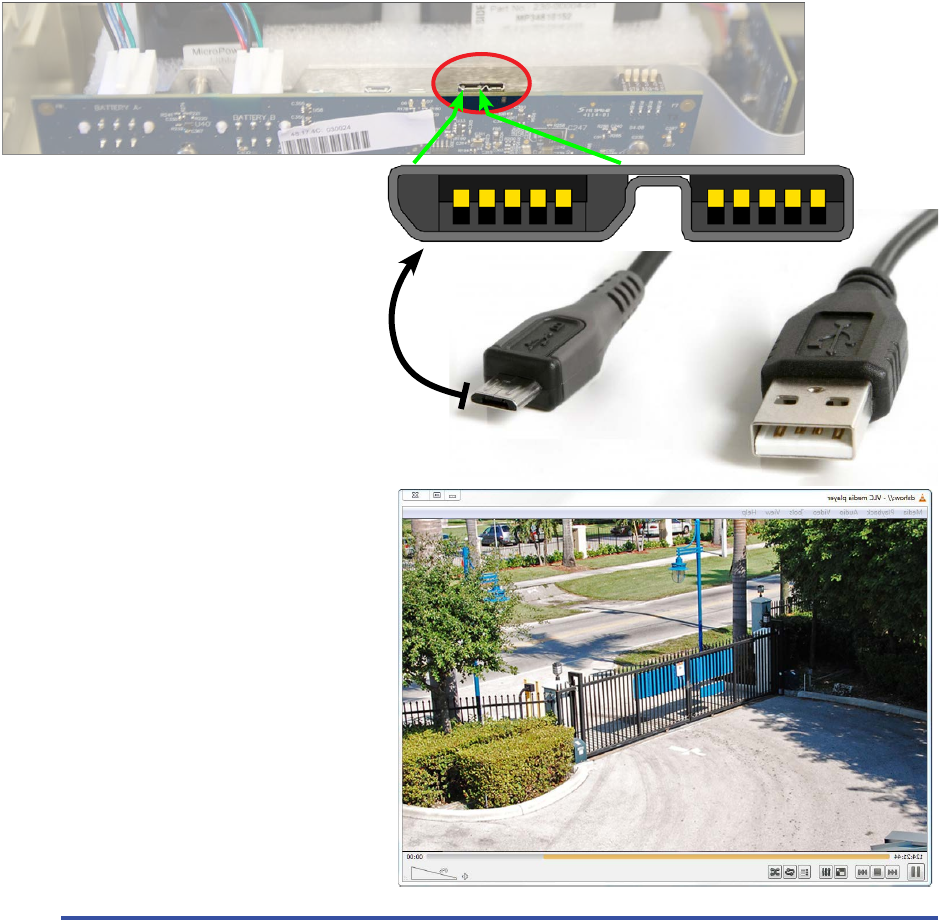
USB Port used for focusing the camera with a
small Windows 7 or Windows 8 or OSX PC
This is a USB 3.0 port, however you can easily
connect a standard Micro USB 2.0 connector
into the (larger) right secon of the socket.
29
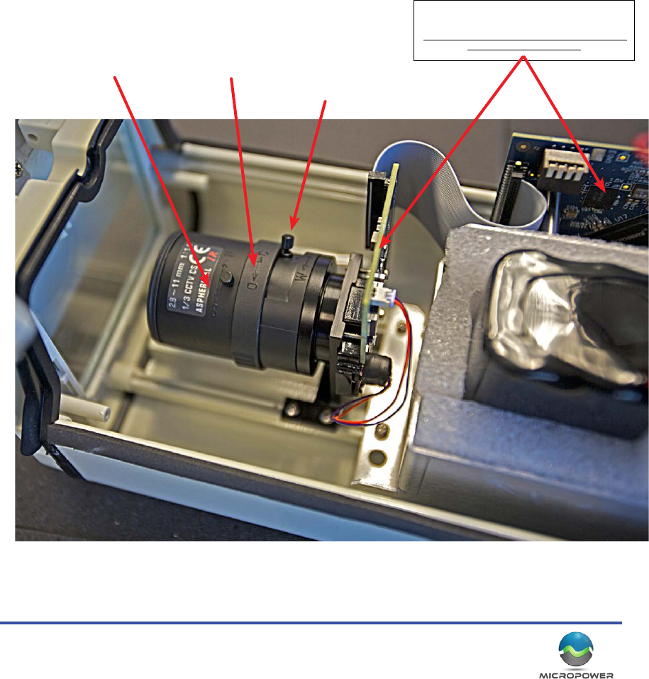
Focusing and Adjusng The Camera
The system uses common “CS-Mount” threaded, mega-pixel CCTV lenses. Standard MicroPower cameras come
equipped with either a 2.8-11mm IR corrected lens, or a 10-40mm IR corrected lens. All the lenses are equipped
with a manual iris control, that in most circumstances, should always be opened up completely to oer the best
low light performance. The telephoto and focus controls should be adjusted to provide the desired eld of view
and magnicaon.
Remember, these are wireless cameras that are more exible for mounng than tradional wired CCTV, so
whenever possible you should try to bring the camera closer to your target, rather than resorng rst to magnifying
it through a more powerful lens. Closer posioning will provide greater clarity and beer low light performance,
and more “pixels on target”.
Note: There are sensive components exposed inside the camera, such as the CCD imager board, and the diplexer
board (seen below). Take care not to touch these parts when focusing the camera, parcularly if the camera is
powered on.
Solveil Camera Equipped with a 2.8-11mm Lens
Main board and the CCD Imager board.
These are sensive parts of the camera system.
Try to avoid contact with these components when
making camera adjustments
Focus Control Iris Control
Zoom Control
MicroPower Technologies
1-877-536-0128 | micropower.com
30
Viewing Live Video at the Camera for Focus and Adjustment
Since the camera is 100% digital, but not actually on the computer network, video from the camera must always
be viewed through the hub. However, with the new Solveil generaon of cameras, a USB port has been added that
can be connected to a Windows based computer. The camera will be detected by your computer as a generic USB
web cam, allowing an installer to use a tablet or small laptop to focus the camera live on the pole.
There are (4) main methods for viewing video when seng up a Solveil camera system.
Direct at the Camera via USB:
The Solveil cameras are equipped with an internal USB port that allows almost any computer running a full version
of Windows 7 or Windows 8, to view the live video as a generic web cam. While this won’t provide signal strength
feedback, it does allow the camera to be adjusted easily in the eld. All you need to do is power on the camera,
and plug your computer’s USB port into the USB port located on the top of the interior main board.
Using a standard Micro USB cord, connect your
computer to the main board of the camera as
shown above. Your computer should take a
few moments to load the driver for the web
cam. You can then use any applicaon that can
show a web cam video feed, such as VLC Player to view
the resulng video from the camera.
[Launch VLC player, select “Open Capture
Device”, select “Direct Show”, and choose
“MicroPower” as the camera]
When the adjustments are made, carefully
remove the cable and securely close the camera
housing, and lock the camera latch.
USB 2.0 Port, plug in this side
31
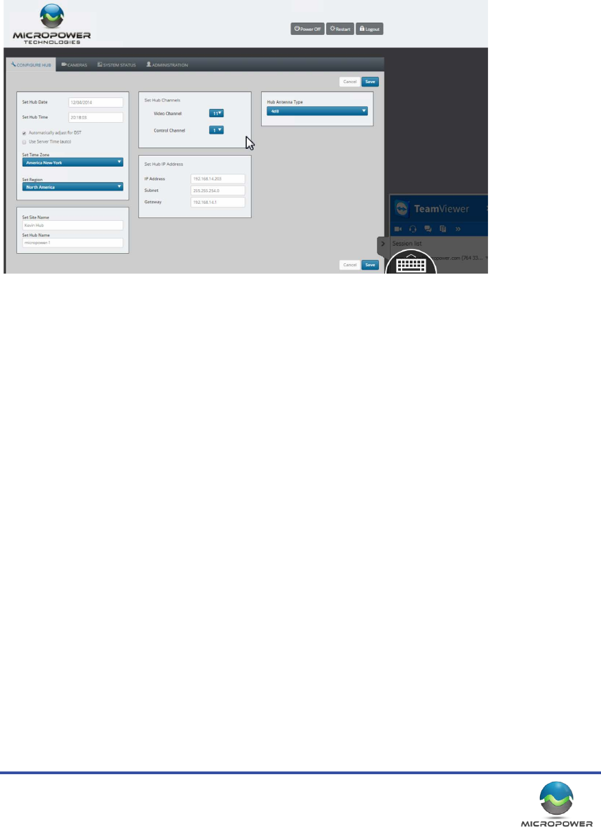
Remote Desktop Access (preferred):
The second method oen proves to be the most useful and versale. It requires that you have a computer such
as a laptop that is capable of communicang with the hub. This computer will also need an Internet connecon,
either from from the host network, or, via a wireless devices such as a cellular to WiFi “MyFi” type device. Using
remote desktop soware such as “LogMeIn™” or our favorite, “TeamViewer™” you can use the remote desktop
app on your personal smart phone (Android or iPhone) to directly access your computer.
This method allows you to see the web interface, view signal strengths, make seng changes and preview video
with full visibility to the system performance. An addional benet is that most commercial remote desktop
packages generally do not require any port forwarding issues, or network changes to provide remote access.
VMS Client Access:
The third most common method requires that the hub is loaded and congured to the VMS that will be recording
the video, and that the VMS is set up for remote viewing access. Most modern VMS plaorms oer iPhone or
Android remote client apps that can be used to log directly into the VMS and view the video being produced by
the cameras. This method will strictly show you video, and is not useful for accessing signal strengths or making
changes to the Solveil setup.
Cell Phones:
Lastly, oen people just take the more simple, “Two guys with cell phones” approach. It simply requires that one
installer remains inside with access to the hub, and communicates via cell phone with the installer on the camera
pole.
Keep in mind that this sll requires a computer and for that computer to have direct access to communicate with
the hub. If an internet connecon can be obtained, then you probably have everything you need to use the more
preferred remote desktop method, that will then provide the camera installer direct access to the video.
Screen shot from the iPhone TeamViewer App, connected to a Solveil hub

MicroPower Technologies
1-877-536-0128 | micropower.com
32
Redacted

33

MicroPower Technologies
1-877-536-0128 | micropower.com
34

35
Contacng MicroPower Customer Support
MicroPower’s customer support strategy is through a network of best-in-class business partners including OEMs,
systems integrators and systems resellers. If your MicroPower product was purchased directly from a MicroPower
business partner, that partner is the rst point of contact for technical support. If the business partner cannot
resolve a problem, then the partner will contact MicroPower.
Web Support: hp://www.micropower.com
Email Support: help@micropower.com
Toll Free Phone Support
Worldwide:
+1-877-536-0128
+1-858-914-5198
Press opon 2 for Customer Support
Fax Support – Worldwide: +1-858-947-3907

MicroPower Technologies
1-877-536-0128 | micropower.com
36
MicroPower Technologies
END-USER LICENSE AGREEMENT
for IP SECURITY SYSTEM SOFTWARE AND/OR FIRMWARE
IMPORTANT - READ CAREFULLY
This End User Soware License Agreement (this “EULA”) is a legal agreement between you, the individual or enty that has agreed to pay for the rights granted
herein (“Licensee”), and MicroPower Technologies, Inc., a Delaware corporaon (“MPT”). This EULA governs Licensee’s possession and use of the Soware and the
Documentaon (each as dened below).
BY CHECKING AND/OR CLICKING “I ACCEPT” OR A SIMILAR BOX OR BUTTON ASSOCIATED WITH THIS EULA AT THE BEGINNING OF THE SOFTWARE DOWNLOAD,
INSTALLATION, OR ACTIVATION PROCESS, BY INSTALLING ANY OF THE SOFTWARE, BY ACTIVATING ANY OF THE SOFTWARE WITH ANY ASSOCIATED LICENSE KEY, OR BY
USING ANY OF THE SOFTWARE, LICENSEE AGREES TO ALL OF THE TERMS AND CONDITIONS IN THIS EULA. IF LICENSEE DOES NOT AGREE TO ALL OF THE TERMS AND
CONDITIONS IN THIS EULA, LICENSEE MUST NOT INSTALL, ACTIVATE, OR USE ANY OF THE SOFTWARE, AND LICENSEE MUST NOT CHECK AND/OR CLICK “I ACCEPT”
OR ANY SIMILAR BOX OR BUTTON ASSOCIATED WITH THIS EULA DURING THE SOFTWARE DOWNLOAD, INSTALLATION, OR ACTIVATION PROCESS. IF LICENSEE
DOES NOT AGREE TO ALL OF THE TERMS AND CONDITIONS IN THIS EULA, LICENSEE MAY RETURN THE UNUSED SOFTWARE FOR A FULL REFUND, PROVIDED THAT
LICENSEE’S RIGHT TO RETURN THE UNUSED SOFTWARE FOR A FULL REFUND EXPIRES THIRTY (30) DAYS AFTER THE PURCHASE OF THE SOFTWARE FROM MPT OR A
MPT-AUTHORIZED RESELLER OR DISTRIBUTOR, AND APPLIES ONLY IF LICENSEE IS THE ORIGINAL END USER PURCHASER.
1. DEFINITIONS. As used herein, the following terms shall have the following meanings:
1.1. “Documentaon” means any and all end user documentaon provided by MPT in connecon with the Soware, and all
Updates thereto.
1.2. “Factory Installed Soware” means Soware that is installed by MPT on a MPT hardware product prior to delivery of that
MPT hardware product to Licensee, and all Updates thereto. Factory Installed Soware may include, without limitaon, TrustLinx rmware, and certain third party
le server programs.
1.3. “GPL Soware” refers to certain open source soware that MPT may provide to Licensee in connecon with a MPT hardware
product, including but not limited to the Linux soware provided by MPT in connecon with the MPT-C20S, MPT-C20S-IR, MPT-H10HA, MPT-H10AO products.
GPL Soware is provided by MPT to Licensee solely under the terms of the GNU General Public License, Version 2, June 1991 (the “GNU GPL”), a copy of which
accompanies this Agreement. Consistent with the requirements of the GNU GPL, MPT will provide a complete machine-readable copy of the source code for GPL
Soware for a charge of no more than MPT’s cost of physically performing such distribuon, provided that such copy is requested within three (3) years following
Licensee’s receipt of the corresponding GPL Soware from MPT.
1.4. “Remote Soware” means Soware that is meant to be installed on Licensee’s own hardware and that is not installed by MPT or a MPT reseller on a MPT
hardware product prior to delivery of that MPT hardware product to Licensee, and all Updates thereto. Remote Soware may include, without limitaon, MPT’s Web
Interface or GUI program.
1.5. “Soware” means all soware and rmware that accompanies this EULA, all copies thereof, all media associated therewith, and all Updates thereto; provided
that the term “Soware” does mean any soware or other materials for which a separate end user license agreement is provided (including but not limited to the
GPL Soware).
1.6. “Updates” means any and all updates, upgrades, new releases, modicaons, and/or supplements that may be provided by MPT from me to me, whether
through an online download process or otherwise.
1.7. “Use” means to install, store, load, execute, and display one copy of the Soware on one device at a me for Licensee’s internal business purposes.
2. LICENSE GRANTS.
2.1. Soware. Subject to all terms and condions in this EULA, MPT hereby grants to Licensee a limited, revocable, non exclusive, non sublicenseable license to:
(a) Use Factory Installed Soware, only in object code form, and only on the MPT hardware products that are purchased by Licensee and that contain such soware
when rst delivered to Licensee, provided that Licensee may not use Factory Installed Soware in connecon with any IP video cameras or IP video camera
subsystems that were not purchased from MPT, and provided further that
(i) MPT-C20S rmware may only be used with the MPT-C20S specied in the corresponding invoice;
(ii) MPT-C20S-IR rmware may only be used with the MPT-C20s-IR specied in the corresponding invoice
(iii) MPT-H10HA rmware may only be used with the MPT-H10HA specied in the corresponding invoice.
(b) Use Remote Soware, only in object code form, and only on the number of Licensee computers for which Licensee has purchased a license (as specied in the
corresponding invoice).
2.2. Documentaon. Subject to all terms and condions in this EULA, MPT hereby grants to Licensee a limited, revocable,
non-exclusive, non-sublicenseable license to copy and use the Documentaon to the limited extent reasonably necessary to support
Licensee’s permissible Use of the Soware.
3. OWNERSHIP. Licensee acknowledges and agrees that MPT, its suppliers, and/or its licensors, as applicable, own and shall retain all rights, tle, and interest in and
to the Soware and the Documentaon, including but not limited to all patents, trademarks, trade names, invenons, copyrights, know how, trade secrets, and
other intellectual and industrial property rights (and any corresponding applicaons or registraons) related to the Soware or the Documentaon. MPT’s suppliers
and licensors are intended beneciaries under this EULA and independently may protect their rights in the Soware and the Documentaon in the event of any
infringement or breach of this EULA.
4. RESERVATION OF RIGHTS. Licensee acknowledges and agrees that the Soware and the Documentaon have been licensed to Licensee pursuant to the terms
and condions of this EULA, and that the Soware and the Documentaon have not been sold to Licensee. MPT and its suppliers and licensors reserve all rights not
expressly granted herein. Licensee shall not use or copy the Soware or the Documentaon except as is expressly authorized in this EULA. Licensee acknowledges
and agrees that the Soware and the Documentaon are protected by United States copyright laws and internaonal treaty provisions. Except as otherwise
expressly provided herein, Licensee must treat the Soware and the Documentaon like any other copyrighted material. Licensee shall not knowingly take any acon
that would cause the Soware or the Documentaon to be placed in the public domain.
5. RESTRICTIONS.
5.1. Usage Restricons. Licensee shall not permit any person other than Licensee’s employees and authorized agents to possess
or use the Soware or the Documentaon, and Licensee shall cause all such employees and authorized agents to abide by all terms and condions imposed upon
Licensee herein. Licensee may not exceed the number of licenses, agents, ers, nodes, seats, or other Use restricons or authorizaons agreed to and paid for by
Licensee. Licensee shall not use the Soware to operate nuclear facilies, life support, or any other mission crical applicaon where human life or property may
be at stake, and Licensee understands that the Soware is not designed for such purposes and that its failure in such cases could lead to death, personal injury, or
severe property or environmental damage for which MPT and its suppliers and licensors are not responsible. Some Soware may require license keys or contain
other technical protecon measures. Licensee acknowledges that MPT may monitor Licensee’s compliance with Use restricons and authorizaons, remotely or
otherwise. If MPT makes a license management program available which records and reports Soware usage informaon, Licensee agrees to appropriately install,
congure, and execute such license management program beginning no later than one hundred and eighty (180) days from the date it is made available to Licensee
and connuing for the period that the Soware is used.
5.2. No Transfer. Licensee may not, and agrees that it will not, transfer, assign, rent, lease, lend, resell, or in any way distribute or transfer the Soware or the
Documentaon (or any rights in this EULA, the Soware, or the Documentaon) to any third pares, including by operaon of law, without MPT’s prior wrien
approval, payment to MPT of any applicable fees, and compliance with applicable third party terms. Upon any approved transfer of this EULA, Licensee’s rights
hereunder will terminate and Licensee will immediately deliver the Soware, the Documentaon, and all copies thereof to the transferee. The transferee must agree
in wring to the terms of this EULA and, upon such agreement, the transferee will be considered the “Licensee” for purposes of this EULA. Licensee may transfer
Factory Installed Soware only upon transfer of the associated MPT hardware product.
5.3. No Reverse Engineering; No Modicaon. To the maximum extent permied by applicable law, Licensee shall not reverse engineer, disassemble, decrypt, or
decompile the Soware, or otherwise aempt to discover, reconstruct, or idenfy the source code for the Soware or any user interface techniques, algorithms,
logic, protocols, or specicaons included, incorporated, or implemented therein. Furthermore, to the maximum extent permied by applicable law, Licensee shall

37
not modify, port, or translate the Soware or the Documentaon. Where Licensee has other rights with respect to the Soware or the Documentaon mandated
under statute, Licensee will provide MPT with reasonably detailed informaon regarding any intended modicaons, porng, translaons, reverse engineering,
disassembly, decrypon, or decompilaon, and the purposes therefore.
5.4. Proprietary Noces and Legends. If Licensee makes any copies of the Soware or the Documentaon in accordance with this EULA, Licensee must reproduce in
all such copies all proprietary noces and legends contained in the originals.
5.5. Updates. Upon Licensee’s installaon of any Update to Soware, Licensee shall have no further rights, and MPT shall have no further obligaons, with respect
to those porons of the Soware that such Update was intended to replace. If addional or dierent license terms or condions accompany an Update, Licensee
acknowledges and agrees that Licensee’s Use of that Update will be subject to those addional or dierent terms and condions.
5.6. Export Restricons; Compliance with Laws. Licensee agrees that Licensee will not, directly or indirectly, export or transmit the Soware or the Documentaon
to any country, enty, or person to which such export or transmission is restricted by any applicable government regulaon or statute without the prior wrien
consent, if required, of the governmental enty as may have jurisdicon over such export or transmission. Licensee agrees to comply with and conform to all
applicable laws, regulaons, and ordinances relang to Licensee’s use of the Soware and/or the Documentaon.
6. RESPONSIBILITIES OF LICENSEE.
6.1. Payment. In consideraon for the licenses and rights granted to Licensee herein, Licensee agrees to pay all amount(s) for such licenses and rights as set forth in
the corresponding invoice, in accordance with the payment terms agreed upon by Licensee.
6.2. Indemnicaon. Licensee hereby agrees to indemnify, protect, defend, and hold MPT and its licensors harmless from and against any and all claims, losses, or
damages (including but not limited to reasonable aorneys’ and experts’ fees) aributable to
(a) Licensee’s use or misuse of the Soware or the Documentaon, or
(b) any failure by Licensee to comply with any term, condion, or restricon in this EULA.
7. COMPLIANCE AUDIT. MPT shall have the right, upon reasonable noce, to conduct and/or have an independent accounng rm conduct, during normal business
hours on Licensee’s premises under Licensee’s reasonable supervision, an audit to verify Licensee’s compliance with the terms of this EULA. If an audit reveals
underpayments, then Licensee will immediately pay MPT such underpayments together with the costs reasonably incurred by MPT in connecon with the audit and
seeking compliance with this secon.
8. USE OF LICENSEE INFORMATION. With respect to any informaon Licensee provides to MPT in connecon with the Soware or the Documentaon, MPT may use
such informaon for any purpose without restricon, including, without limitaon, for product support and development purposes, provided that MPT will not use
such informaon in a form that idenes Licensee.
9. TERM AND TERMINATION.
9.1. General. Except as provided below with respect to evaluaon and limited term licenses, this EULA and the license(s) granted herein will remain eecve unl
terminated. Licensee may terminate this EULA and the licenses granted herein by ceasing all use of the Soware and the Documentaon, and returning all copies of
the Soware and the Documentaon to MPT. This EULA (including but not limited to the licenses granted to Licensee herein) will automacally terminate if Licensee
fails to comply with any term or condion of this EULA.
9.2. Evaluaon and Term Licenses. If the Soware and the Documentaon have been licensed to Licensee for evaluaon purposes, this EULA will be eecve
only unl the end of the designated evaluaon period. If the Soware and the Documentaon have been licensed to Licensee for a limited term as specied
in the applicable sales acknowledgment, invoice, or otherwise, then this EULA will be eecve only unl the end of such term. Soware that is subject to any
evaluaon or limited term license may contain code that can disable most or all of the features of such soware upon expiraon of such evaluaon or limited term
license, and unless Licensee has paid the applicable license fee for any addional licenses, Licensee shall have no rights to use such Soware or the corresponding
Documentaon upon expiraon of any such license.
9.3. Obligaons Upon Terminaon or Expiraon. Licensee agrees, upon any terminaon or expiraon of this EULA, to cease use of, and to destroy or return to MPT,
all copies of the Soware and the Documentaon. At MPT’s request, Licensee will cerfy in wring to MPT that Licensee has complied with these requirements.
Notwithstanding anything in this EULA to the contrary, Secons 1, 3, 4, 5.3, 5.6, 6, 7, 8, 9, 10.2, 10.3, 11, 12, and 13 of this EULA shall survive any expiraon or
terminaon of this EULA and connue in perpetuity.
10. LIMITED WARRANTY; DISCLAIMER; LIMITATION OF LIABILITY.
10.1. refer to micropower.com for current warranty informaon
11. U.S. GOVERNMENT RESTRICTED RIGHTS.
11.1. Commercial Soware. The Soware and the Documentaon are deemed to be “commercial computer soware” and
“commercial computer soware documentaon,” respecvely, for purposes of Federal Acquision Regulaons (“FAR”) 12.212 and the Defense FAR Supplement
(“DFARS”) 227.7202-1, 227.7202-3, and 227.7202-4, and the restricons set forth in such regulaons, and this EULA shall be deemed to be the license described in
such regulaons. Any use, modicaon, reproducon, release, performance, display, or disclosure of the Soware or the Documentaon by any agency, department,
or enty of the United States Government (the “Government”) shall be governed solely by the terms of this EULA and is prohibited except to the extent expressly
permied by the terms of this EULA. The Soware and the Documentaon are also deemed to be “restricted computer soware” for purposes of FAR 52.227-14(g)
(3) (Alternate III (June 1987)) and FAR 52.227-19, which clauses are incorporated herein by reference subject to the express restricons and prohibions set forth
above.
11.2. Certain Technical Data. Any technical data provided by MPT in connecon with the Soware or the Documentaon that is not covered by the above provisions
is deemed to be “technical informaon related to commercial computer soware or commercial computer soware documentaon” for purposes of FAR 12.212 and
the restricons set forth therein, and is deemed to be “technical data or informaon related or pertaining to commercial items or processes” developed at private
expense for purposes of DFARS 227.7102-1
and 227.7102 2 and the restricons set forth therein, and this EULA shall be deemed to be the license described in such regulaons. Any use, modicaon,
reproducon, release, performance, display, or disclosure of such technical data by the Government shall be governed solely by the terms of this EULA and is
prohibited except to the extent expressly permied by the terms of this EULA. Such technical data is also deemed to be “limited rights data” as dened in FAR
52.227-14(a) (Alternate I (June 1987)) and for purposes of FAR 52.227-14(g)(2) (Alternate II (June 1987)), which clauses are incorporated herein by reference subject
to the express restricons and prohibions set forth above. Such technical data shall also be deemed to be “technical data” for purposes of DFARS 252.227-7015,
which clause is incorporated herein by reference subject to the express restricons and prohibions set forth above.
11.3. Third Party Acceptance of Restricons. Licensee shall not provide the Soware, the Documentaon, or the technical data described in Secon 11.2 above
to any party, including but not limited to the Government, unless such third party accepts the same restricons as are set forth in this Secon 11. Licensee is
responsible for ensuring that the proper noce is given to all such third pares and that the Soware, the Documentaon, and such technical data is properly
marked with the required legends. Nothing in this Secon 11.3 shall be deemed to modify the restricons on transfer or disclosure set forth elsewhere in this EULA.
12. GOVERNING LAW; ENFORCEMENT.
12.1. Governing Law. This EULA and the rights and obligaons of the pares hereunder shall be governed by the laws of the State of California, without reference to
conicts of laws principles; provided, however, that if the Soware and the Documentaon is licensed outside the United States, then certain local laws may apply.
The pares agree to the non exclusive jurisdicon of the state and federal courts in San Diego County, California in connecon with the ligaon of any dispute
pertaining to this EULA and waive any objecon to such jurisdicon based on venue or personal jurisdicon. IN ADDITION, THIS EULA WILL NOT BE GOVERNED OR
INTERPRETED IN ANY WAY BY REFERRING TO ANY LAW BASED ON THE UNIFORM COMPUTER INFORMATION TRANSACTIONS ACT (UCITA), EVEN IF THAT LAW HAS
BEEN ADOPTED IN CALIFORNIA, AND THE UNITED NATIONS CONVENTION ON CONTRACTS FOR THE INTERNATIONAL SALE OF GOODS IS HEREBY EXCLUDED.
12.2. Equitable Relief. Licensee acknowledges that any actual or threatened breach of the provisions of this EULA will constute immediate, irreparable harm to MPT
for which monetary damages would be an inadequate remedy; that injuncve relief is an appropriate remedy for any such breach or threatened breach; and that, in
such event, MPT will be entled to immediate injuncve relief without the requirement of posng bond.
13. MISCELLANEOUS. Except as otherwise expressly agreed in a wrien, signed agreement between MPT and Licensee, this EULA sets forth the enre agreement
between MPT and Licensee with respect to the Soware, the Documentaon, and/or Licensee’s use of the Soware and the Documentaon, and it is expressly
agreed that the terms of this EULA will supersede the terms in any of Licensee’s purchase orders or other ordering documents. There are no implied licenses with
respect to the Soware or the Documentaon. No provision of this EULA may be waived, modied, or superseded except by a wrien instrument signed by each
of MPT and Licensee. No failure or delay in exercising any right or remedy shall operate as a waiver of any such (or any other) right or remedy. The language of this
EULA shall be construed as a whole, according to its fair meaning and intent, and not strictly for or against either party, regardless of who draed or was principally
responsible for draing this EULA or any specic term or condion hereof. This EULA shall bind and inure to the benet of the pares and their successors and

MicroPower Technologies
1-877-536-0128 | micropower.com
38
permied assigns. Both pares are acng as independent contractors with respect to the acvies hereunder. In the event of any legal proceeding between the
pares arising out of or related to this EULA, the prevailing party shall be entled to recover, in addion to any other relief awarded or granted, its costs and
expenses (including but not limited to reasonable aorneys’ and expert witness’ fees) incurred in any such proceeding. If any provision in this EULA is invalid or
unenforceable, such provision shall be construed, limited, or altered, as reasonably necessary, to eliminate the invalidity or unenforceability and all other provisions
of this EULA shall remain in eect.
-------------------------------------------------------------------------------------------------------------------------------------------------------------------------------
Should Licensee have any quesons concerning this EULA, or if Licensee desires to contact MicroPower Technologies for any reason, please contact the company at:
4350 Execuve Drive, Suite 325, San Diego, CA 92121, or send an email to MicroPower Technologies at help@micropower.com.
GNU GENERAL PUBLIC LICENSE
TERMS AND CONDITIONS FOR COPYING, DISTRIBUTION AND MODIFICATION
0. This License applies to any program or other work which contains a noce placed by the copyright holder saying it may be distributed under the terms of this
General Public License. The “Program”, below, refers to any such program or work, and a “work based on the Program” means either the Program or any derivave
work under copyright law: that is to say, a work containing the Program or a poron of it, either verbam or with modicaons and/or translated into another
language. (Hereinaer, translaon is included without limitaon in the term “modicaon”.) Each licensee is addressed as “you”.
Acvies other than copying, distribuon and modicaon are not covered by this License; they are outside its scope. The act of running the Program is not
restricted, and the output from the Program is covered only if its contents constute a work based on the Program (independent of having been made by running
the Program). Whether that is true depends on what the Program does.
1. You may copy and distribute verbam copies of the Program’s source code as you receive it, in any medium, provided that you conspicuously and appropriately
publish on each copy an appropriate copyright noce and disclaimer of warranty; keep intact all the noces that refer to this License and to the absence of any
warranty; and give any other recipients of the Program a copy of this License along with the Program.
You may charge a fee for the physical act of transferring a copy, and you may at your opon oer warranty protecon in exchange for a fee.
2. You may modify your copy or copies of the Program or any poron of it, thus forming a work based on the Program, and copy and distribute such modicaons or
work under the terms of Secon 1 above, provided that you also meet all of these condions:
You must cause the modied les to carry prominent noces stang that you changed the les and the date of any change.
You must cause any work that you distribute or publish, that in whole or in part contains or is derived from the Program or any part thereof, to be licensed as a
whole at no charge to all third pares under the terms of this License.
If the modied program normally reads commands interacvely when run, you must cause it, when started running for such interacve use in the most ordinary way,
to print or display an announcement including an appropriate copyright noce and a noce that there is no warranty (or else, saying that you provide a warranty)
and that users may redistribute the program under these condions, and telling the user how to view a copy of this License. (Excepon: if the Program itself is
interacve but does not normally print such an announcement, your work based on the Program is not required to print an announcement.)
These requirements apply to the modied work as a whole. If idenable secons of that work are not derived from the Program, and can be reasonably considered
independent and separate works in themselves, then this License, and its terms, do not apply to those secons when you distribute them as separate works. But
when you distribute the same secons as part of a whole which is a work based on the Program, the distribuon of the whole must be on the terms of this License,
whose permissions for other licensees extend to the enre whole, and thus to each and every part regardless of who wrote it.
Thus, it is not the intent of this secon to claim rights or contest your rights to work wrien enrely by you; rather, the intent is to exercise the right to control the
distribuon of derivave or collecve works based on the Program.
In addion, mere aggregaon of another work not based on the Program with the Program (or with a work based on the Program) on a volume of a storage or
distribuon medium does not bring the other work under the scope of this License.
3. You may copy and distribute the Program (or a work based on it, under Secon 2) in object code or executable form under the terms of Secons 1 and 2 above
provided that you also do one of the following:
Accompany it with the complete corresponding machine-readable source code, which must be distributed under the terms of Secons 1 and 2 above on a medium
customarily used for soware interchange; or,
Accompany it with a wrien oer, valid for at least three years, to give any third party, for a charge no more than your cost of physically performing source
distribuon, a complete machine-readable copy of the corresponding source code, to be distributed under the terms of Secons 1 and 2 above on a medium
customarily used for soware interchange; or,
Accompany it with the informaon you received as to the oer to distribute corresponding source code. (This alternave is allowed only for noncommercial
distribuon and only if you received the program in object code or executable form with such an oer, in accord with Subsecon b above.)
The source code for a work means the preferred form of the work for making modicaons to it. For an executable work, complete source code means all the
source code for all modules it contains, plus any associated interface denion les, plus the scripts used to control compilaon and installaon of the executable.
However, as a special excepon, the source code distributed need not include anything that is normally distributed (in either source or binary form) with the major
components (compiler, kernel, and so on) of the operang system on which the executable runs, unless that component itself accompanies the executable.
If distribuon of executable or object code is made by oering access to copy from a designated place, then oering equivalent access to copy the source code from
the same place counts as distribuon of the source code, even though third pares are not compelled to copy the source along with the object code.
4. You may not copy, modify, sublicense, or distribute the Program except as expressly provided under this License. Any aempt otherwise to copy, modify,
sublicense or distribute the Program is void, and will automacally terminate your rights under this License. However, pares who have received copies, or rights,
from you under this License will not have their licenses terminated so long as such pares remain in full compliance.
5. You are not required to accept this License, since you have not signed it. However, nothing else grants you permission to modify or distribute the Program or its
derivave works. These acons are prohibited by law if you do not accept this License. Therefore, by modifying or distribung the Program (or any work based on
the Program), you indicate your acceptance of this License to do so, and all its terms and condions for copying, distribung or modifying the Program or works
based on it.
6. Each me you redistribute the Program (or any work based on the Program), the recipient automacally receives a license from the original licensor to copy,
distribute or modify the Program subject to these terms and condions. You may not impose any further restricons on the recipients’ exercise of the rights granted
herein. You are not responsible for enforcing compliance by third pares to this License.
7. If, as a consequence of a court judgment or allegaon of patent infringement or for any other reason (not limited to patent issues), condions are imposed on
you (whether by court order, agreement or otherwise) that contradict the condions of this License, they do not excuse you from the condions of this License. If
you cannot distribute so as to sasfy simultaneously your obligaons under this License and any other pernent obligaons, then as a consequence you may not
distribute the Program at all. For example, if a patent license would not permit royalty-free redistribuon of the Program by all those who receive copies directly or
indirectly through you, then the only way you could sasfy both it and this License would be to refrain enrely from distribuon of the Program.
If any poron of this secon is held invalid or unenforceable under any parcular circumstance, the balance of the secon is intended to apply and the secon as a
whole is intended to apply in other circumstances.
It is not the purpose of this secon to induce you to infringe any patents or other property right claims or to contest validity of any such claims; this secon has the
sole purpose of protecng the integrity of the free soware distribuon system, which is implemented by public license pracces. Many people have made generous
contribuons to the wide range of soware distributed through that system in reliance on consistent applicaon of that system; it is up to the author/donor to
decide if he or she is willing to distribute soware through any other system and a licensee cannot impose that choice.
This secon is intended to make thoroughly clear what is believed to be a consequence of the rest of this License.
8. If the distribuon and/or use of the Program is restricted in certain countries either by patents or by copyrighted interfaces, the original copyright holder who
places the Program under this License may add an explicit geographical distribuon limitaon excluding those countries, so that distribuon is permied only in or
among countries not thus excluded. In such case, this License incorporates the limitaon as if wrien in the body of this License.
9. The Free Soware Foundaon may publish revised and/or new versions of the General Public License from me to me. Such new versions will be similar in spirit
to the present version, but may dier in detail to address new problems or concerns. Each version is given a disnguishing version number. If the Program species
a version number of this License which applies to it and “any later version”, you have the opon of following the terms and condions either of that version or of
any later version published by the Free Soware Foundaon. If the Program does not specify a version number of this License, you may choose any version ever
published by the Free Soware Foundaon.
10. If you wish to incorporate parts of the Program into other free programs whose distribuon condions are dierent, write to the author to ask for permission.
For soware that is copyrighted by the Free Soware Foundaon, write to the Free Soware Foundaon; we somemes make excepons for this. Our decision will
be guided by the two goals of preserving the free status of all derivaves of our free soware and of promong the sharing and reuse of soware generally.
NO WARRANTY
11. BECAUSE THE PROGRAM IS LICENSED FREE OF CHARGE; THERE IS NO WARRANTY FOR THE PROGRAM, TO THE EXTENT PERMITTED BY APPLICABLE LAW. EXCEPT
WHEN OTHERWISE STATED IN WRITING THE COPYRIGHT HOLDERS AND/OR OTHER PARTIES PROVIDE THE PROGRAM “AS IS” WITHOUT WARRANTY OF ANY KIND,
EITHER EXPRESSED OR IMPLIED, INCLUDING, BUT NOT LIMITED TO, THE IMPLIED WARRANTIES OF MERCHANTABILITY AND FITNESS FOR A PARTICULAR PURPOSE.
THE ENTIRE RISK AS TO THE QUALITY AND PERFORMANCE OF THE PROGRAM IS WITH YOU. SHOULD THE PROGRAM PROVE DEFECTIVE, YOU ASSUME THE COST OF

39
ALL NECESSARY SERVICING, REPAIR OR CORRECTION.
12. IN NO EVENT UNLESS REQUIRED BY APPLICABLE LAW OR AGREED TO IN WRITING WILL AND COPYRIGHT HOLDER, OR ANY OTHER PARTY WHO MAY
MODIFY AND/OR REDISTRIBUTE THE PROGRAM AS PERMITTED ABOVE, BE LIABLE TO YOU FOR DAMAGES, INCLUDING ANY GENERAL, SPECIAL, INCIDENTAL OR
CONSEQUENTIAL DAMAGES ARISING OUT OF THE USE OR INABILITY TO USE THE PROGRAM (INCLUDING BUT NOT LIMITED TO LOSS OF DATA OR DATA BEING
RENDERED INACCURATE OR LOSSES SUSTAINED BY YOU OR THIRD PARTIES OR A FAILURE OF THE PROGRAM TO OPERATE WITH ANY OTHER PROGRAMS), EVEN IF
SUCH HOLDER OR OTHER PARTY HAS BEEN ADVISED OF THE POSSIBILITY OF SUCH DAMAGES.
END OF TERMS AND CONDITIONS
MicroPower Technologies and its logo are trademarks of MicroPower Technologies, Inc. All other trademarks are the property of their respecve owners.
FCC Compliance Statement (Part 15.19)
Compliance Statement (Part 15.19)
This device complies with Part 15 of the FCC Rules. Operaon is subject to the following two condions:
1. This device may not cause harmful interference, and
2. This device must accept any interference received, including interference that may cause undesired operaon.
Warning (Part 15.21)
Changes or modicaons not expressly approved by the party responsible for compliance could void the user’s
authority to operate the equipment.
FCC Interference Statement (Part 15.105 (b))
This equipment has been tested and found to comply with the limits for a Class B digital device, pursuant to Part
15 of the FCC Rules. These limits are designed to provide reasonable protecon against harmful interference in a
residenal installaon. This equipment generates uses and can radiate radio frequency energy and, if not installed
and used in accordance with the instrucons, may cause harmful interference to radio communicaons. However,
there is no guarantee that interference will not occur in a parcular installaon. If this equipment does cause
harmful interference to radio or television recepon, which can be determined by turning the equipment o and on,
the user is encouraged to try to correct the interference by one of the following measures:
Reorient or relocate the receiving antenna.
Increase the separaon between the equipment and receiver.
Connect the equipment into an outlet on a circuit dierent from that to which the receiver is connected.
Consult the dealer or an experienced radio/TV technician for help.
To comply with FCC/IC RF exposure limits for general populaon / uncontrolled exposure, the antenna(s) used for this transmier
must be installed on outdoor permanent structures to provide a separaon distance of at least 20 cm from all persons and must
not be co-located or operang in conjuncon with any other antenna or transmier.

MicroPower Technologies
1-877-536-0128 | micropower.com
40
Installaon Site Name __________________________________________________________________
Hub IP Address:_______._______._______._______ WB Ch_______ NB CH_______
Camera 0, MAC Address: 48:17:4C:02:______:______, IP Address:_______._______._______._______
Camera 1, MAC Address: 48:17:4C:02:______:______, IP Address:_______._______._______._______
Camera 2, MAC Address: 48:17:4C:02:______:______, IP Address:_______._______._______._______
Camera 3, MAC Address: 48:17:4C:02:______:______, IP Address:_______._______._______._______
Installaon Notes: