MicroTransponder 10001001A Implantable Generator User Manual 26 0001 0000 ENG Rev A Serenity Implantable IFU
MicroTransponder, Inc. Implantable Generator 26 0001 0000 ENG Rev A Serenity Implantable IFU
UserManual.wiki
>
MicroTransponder
>
10001001A User Manual
26-0001-0000-ENG Rev A Serenity Implantable IFU
Navigation menu
Upload a User Manual
Namespaces
Wiki Guide
HTML
PDF
Info
Views
User Manual
Discussion / Help
Navigation
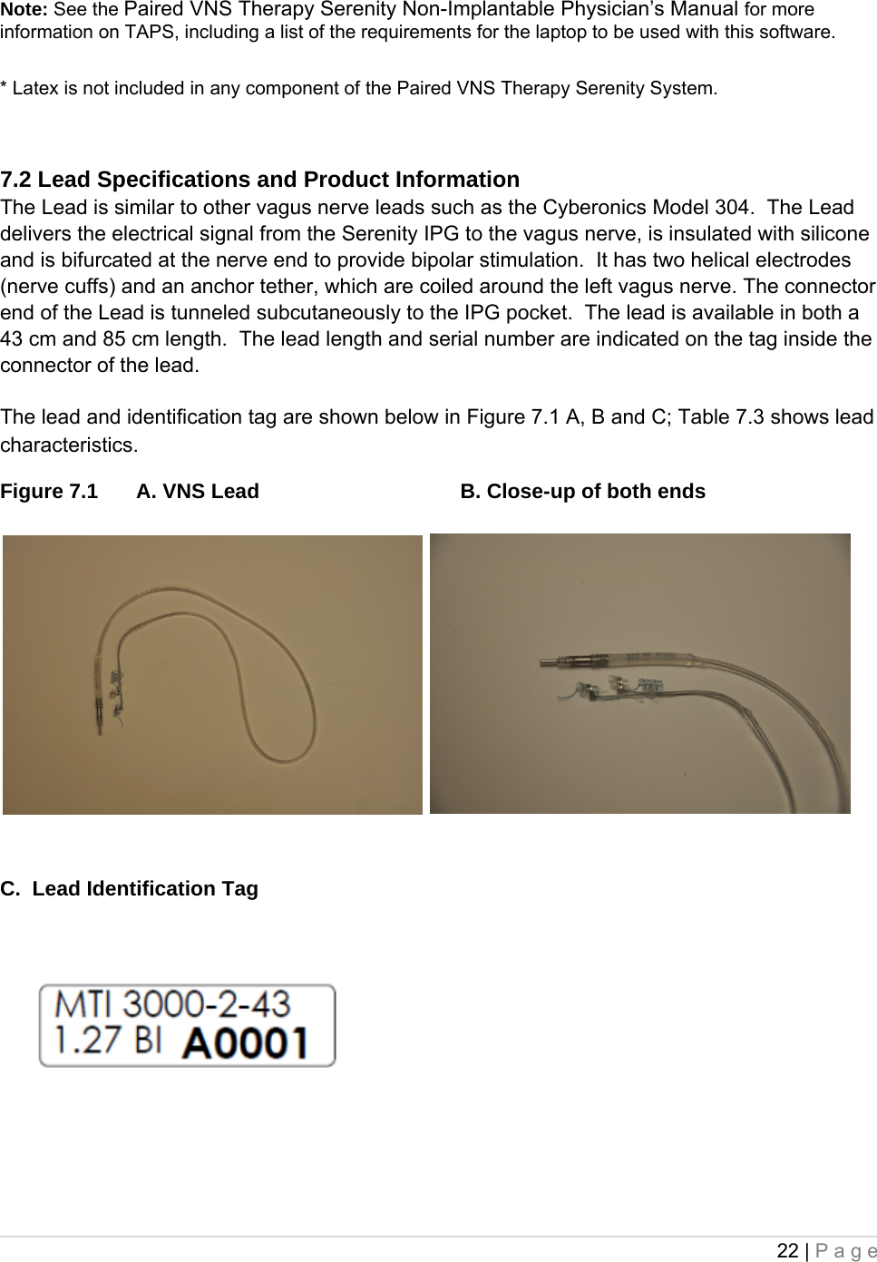
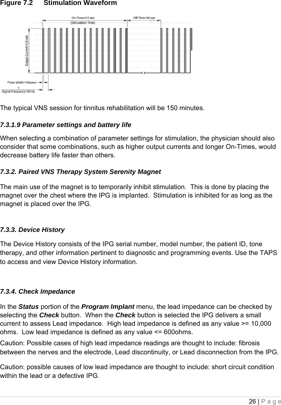
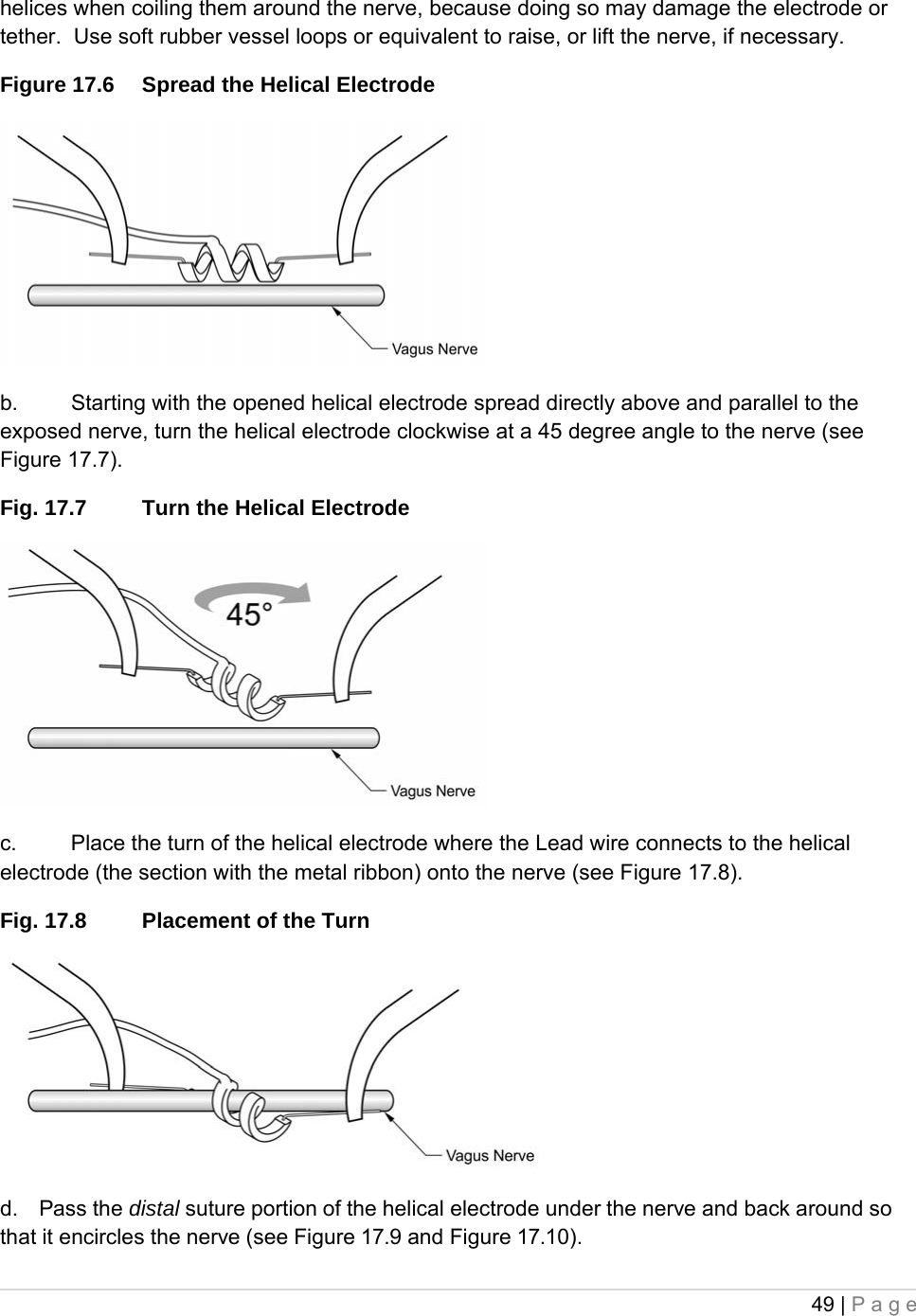
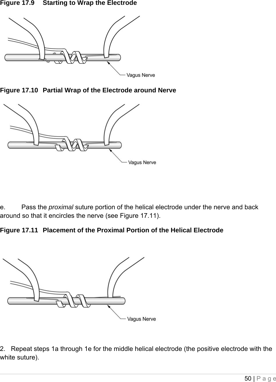
![16 | Page • Do not insert a Lead in the IPG Lead receptacle(s) without first visually verifying that the setscrew(s) is sufficiently retracted to allow insertion. Avoid backing the setscrew(s) out further than needed for Lead insertion. • To avoid damaging (stripping) the setscrew(s) and/or dislodging the setscrew plug(s), insert the hex screwdriver into the center of the setscrew plug, keeping it perpendicular to the IPG. • Inserting the hex screwdriver into the septum can aid in relieving a vacuum that may be created during lead insertion or withdrawal. 5.4. Environmental and Medical Therapy Hazards Patients should exercise reasonable caution in avoiding devices that generate a strong electric or magnetic field. If an IPG ceases operation while in the presence of electromagnetic interference (EMI), moving away from the source may allow it to return to its normal mode of operation. 5.4.1. Hospital and medical environments Paired VNS Therapy Serenity System operation should always be checked by performing device diagnostics after any of the procedures mentioned in this manual. Additional precautions for these procedures are described below. • For clear imaging, patients may need to be specially positioned for mammography procedures because of the location of the IPG in the chest. (Most routine diagnostic procedures, such as fluoroscopy and radiography, are not expected to affect system operation.) • Therapeutic radiation may damage the IPG’s circuitry, although no testing has been done to date and no definite information on radiation effects is available. Sources of such radiation include therapeutic radiation, cobalt machines, and linear accelerators. The radiation effect is cumulative, with the total dosage determining the extent of damage. The effects of exposure to such radiation can range from a temporary disturbance to permanent damage, and may not be detectable immediately. • External defibrillation may damage the IPG. Attempt to minimize current flowing through the IPG and Lead system by following these precautions: • Position defibrillation paddles perpendicular to the IPG and Lead system and as far from the IPG as possible. • Use the lowest clinically appropriate energy output (watt-seconds). • Confirm IPG function after any internal or external defibrillation. • Use of electrosurgery [electrocautery or radio frequency (RF) ablation devices] may damage the IPG. During the VNS implantation procedure, do not use electrosurgical equipment after the IPG has been introduced to the sterile field. When performing other surgical procedures on a patient implanted with a Serenity IPG, attempt to minimize the current flowing through the IPG and Lead system by following these precautions:](https://usermanual.wiki/MicroTransponder/10001001A/User-Guide-1847139-Page-16.png)
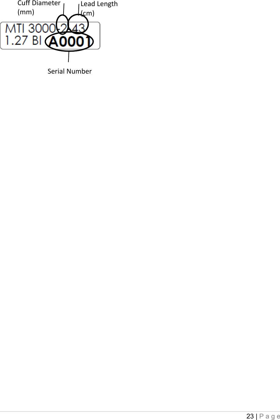
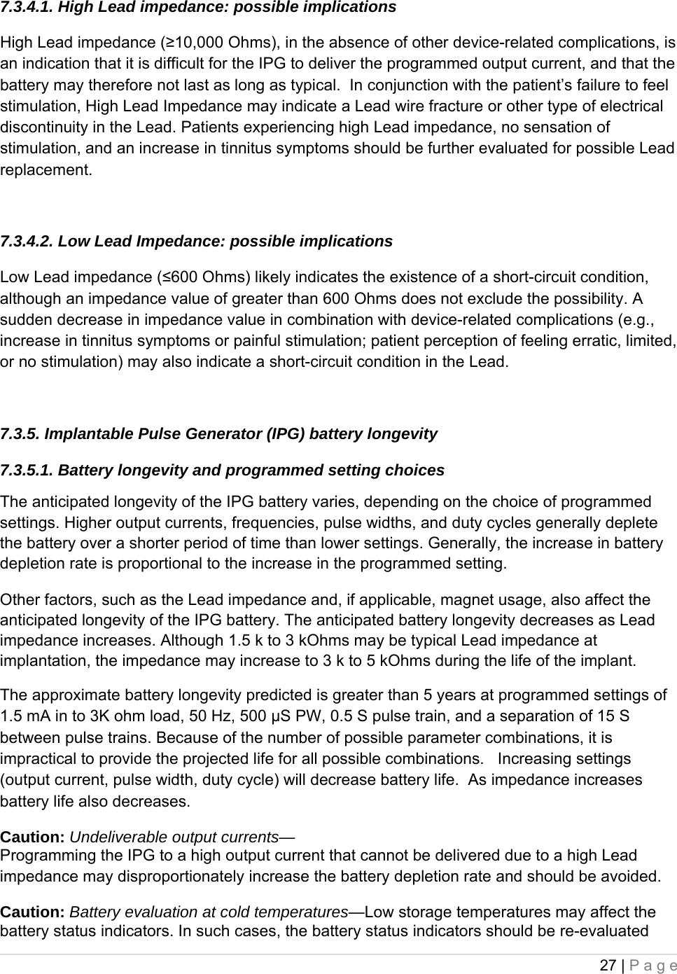
![28 | Page using the System Diagnostics or Generator Diagnostics after the IPG has been at room or body temperature for 30 minutes. 7.3.5.2. Battery status indicators The Programming Software will display warning messages after an interrogation or programming of the IPG if the battery is nearing its depletion. The first indication is an Elective Replacement Indicator (ERI) flag, which indicates less than 15% of the battery life is left (likely nine [9] months or less). The final indication is an End of Life (EOL) flag, which indicates less than 5% of the battery life is left. It is recommended that IPG replacement start being considered at ERI. Please refer to the Paired VNS Therapy Serenity System Non-Implantable Physician’s Manual for additional information in these indicators. 7.4 Implantable Pulse Generator (IPG) Replacement All Paired VNS Therapy Serenity IPGs eventually require surgical replacement as a result of battery depletion. IPG replacement does not, of itself, require Lead replacement unless a Lead discontinuity is suspected. IPG replacement or removal requires dissection to the IPG’s pocket, with care being taken not to damage or cut the Lead. Replacement of the IPG only typically requires 30 minutes or less; replacement of the entire system typically requires approximately 90 minutes. 7.5 Lead Lifetime and Replacement A Lead requires replacement when a Lead discontinuity is suspected. An increase in clinical signs and symptoms may signal a need for Lead replacement. Events that can shorten the life expectancy of the Lead are as follows: • Blunt trauma to the neck and/or any area of the body beneath which the Lead is implanted • Twisting or picking (Twiddler’s Syndrome) at either the implanted Lead or the IPG • Improper surgical implantation of the Paired VNS Therapy Serenity System, including (but not limited to) providing an inadequate strain-relief loop, placing sutures directly on the Lead body rather than using the tie-downs, and suturing the Lead body to muscle. Caution: Lead replacement or removal—Replacing or removing Leads because of lack of efficacy is a medical judgment that includes the patient’s desires and health status, and must be carefully weighed against the known and unknown risks of surgery. At present, no known long-term hazards or risks are associated with leaving the Lead implanted, beyond those already mentioned in this multi-part physician’s manual. All precautions and contraindications still should be observed (see “Troubleshooting”, Section 8 below). 7.6 Signs of End of Life The most common reason for the absence of stimulation is battery depletion, although there](https://usermanual.wiki/MicroTransponder/10001001A/User-Guide-1847139-Page-28.png)
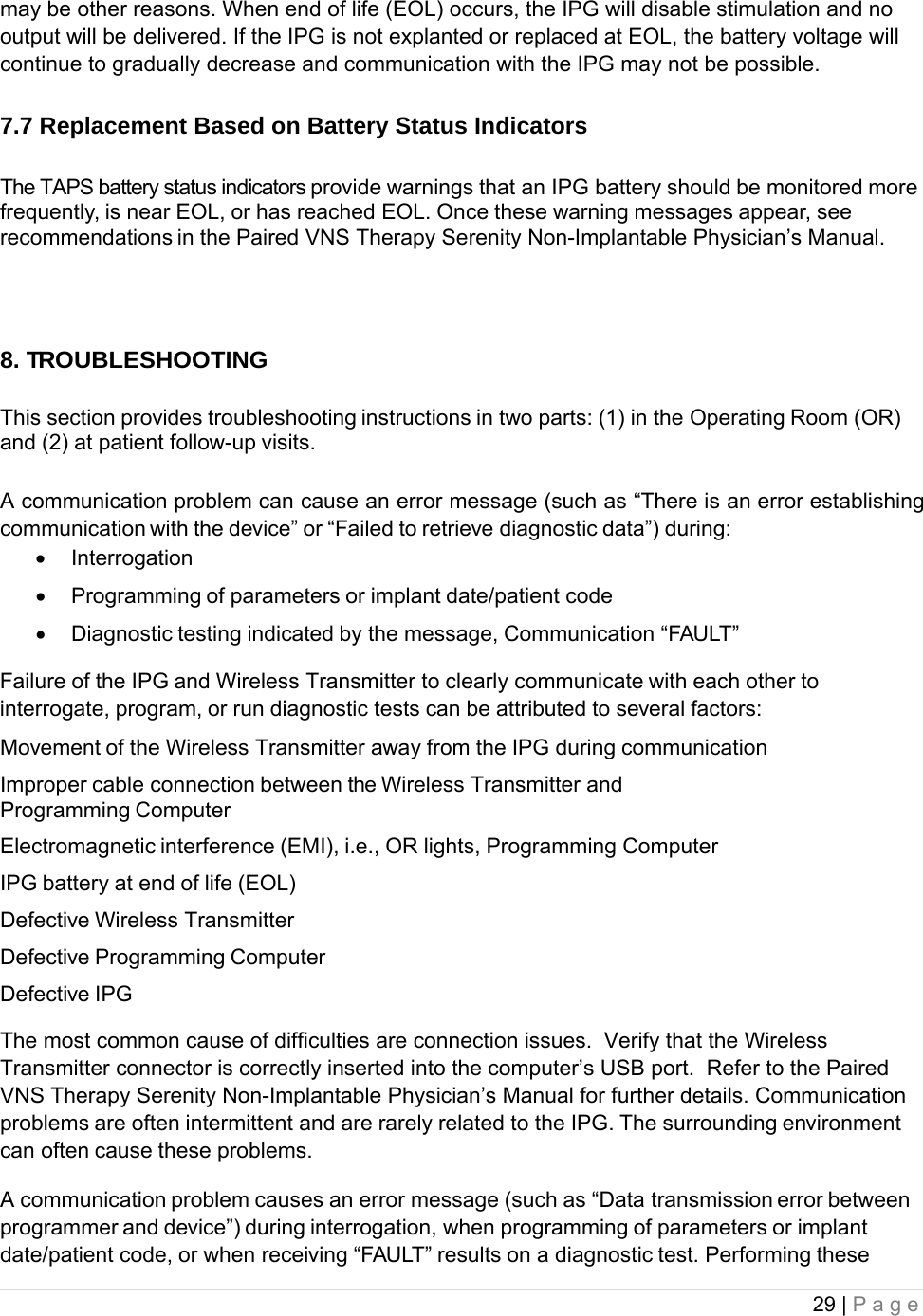
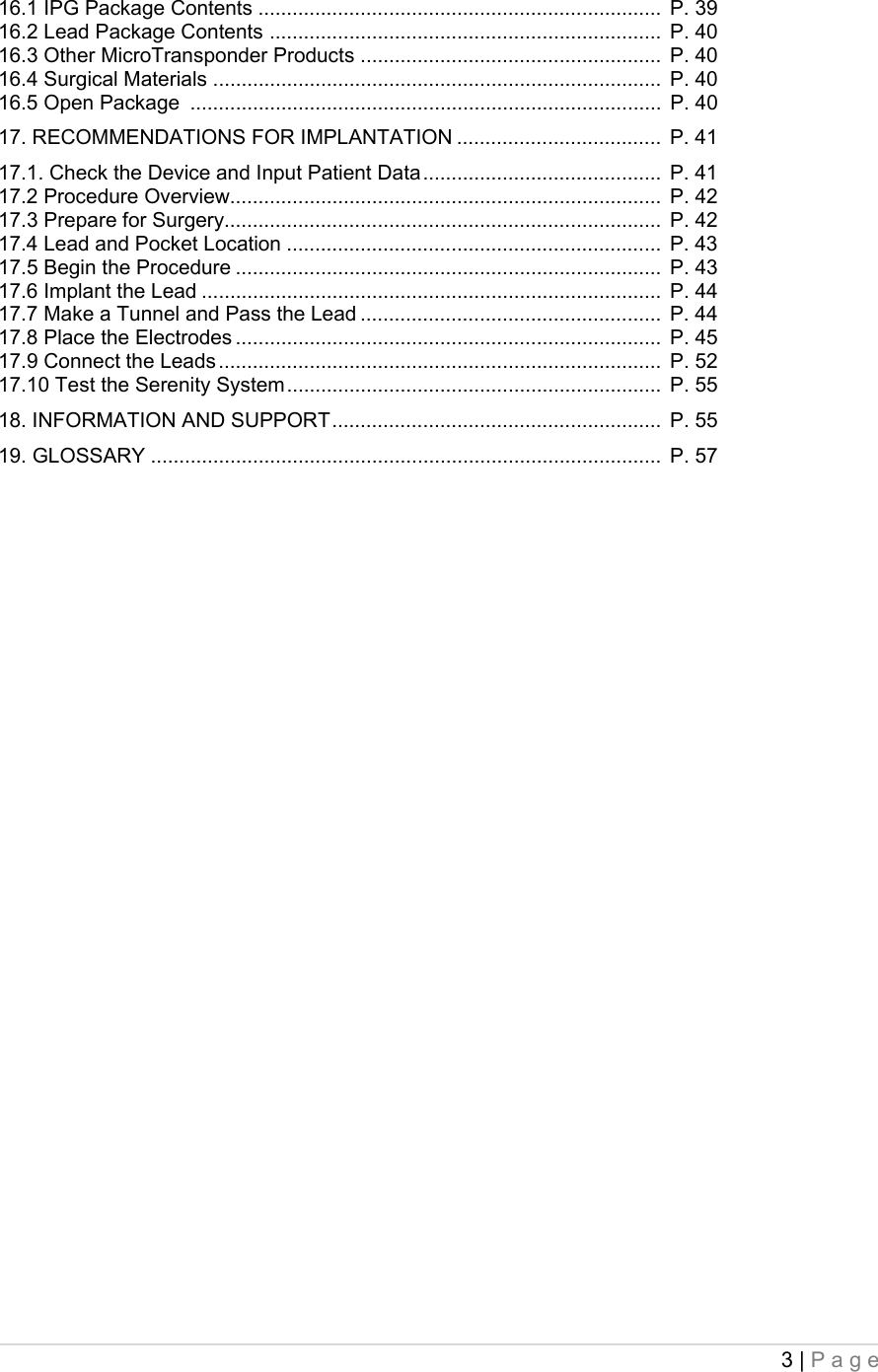
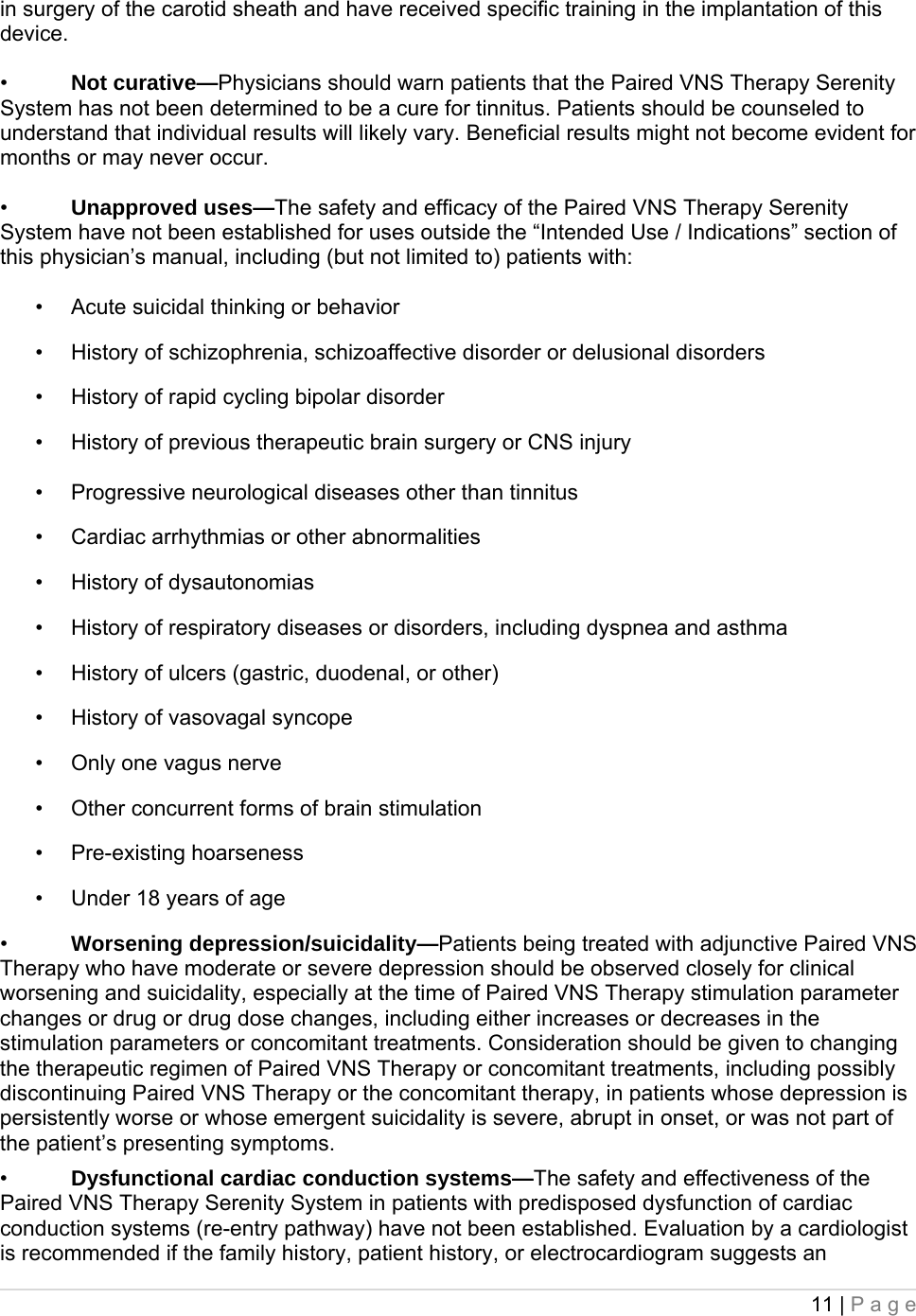
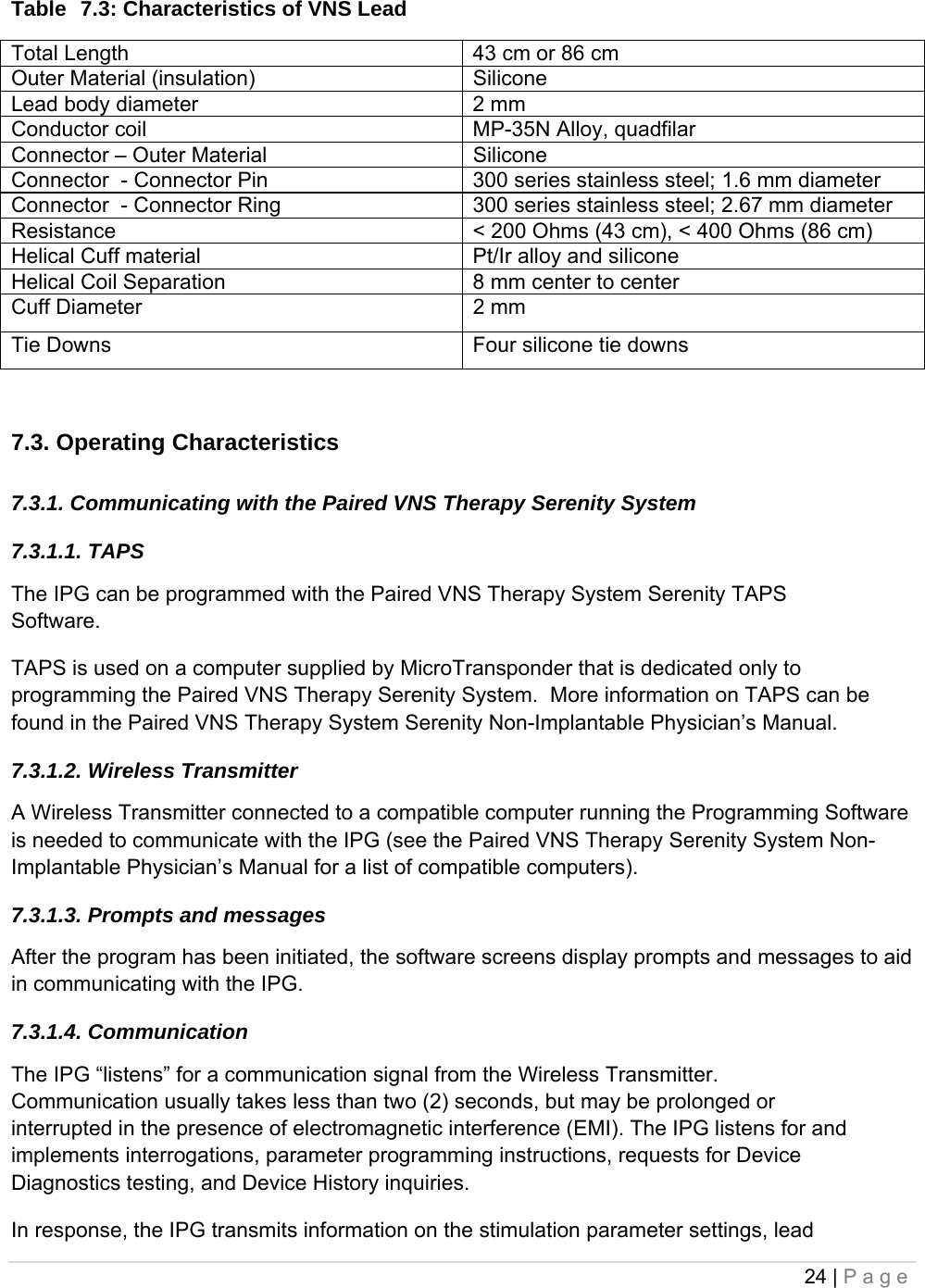
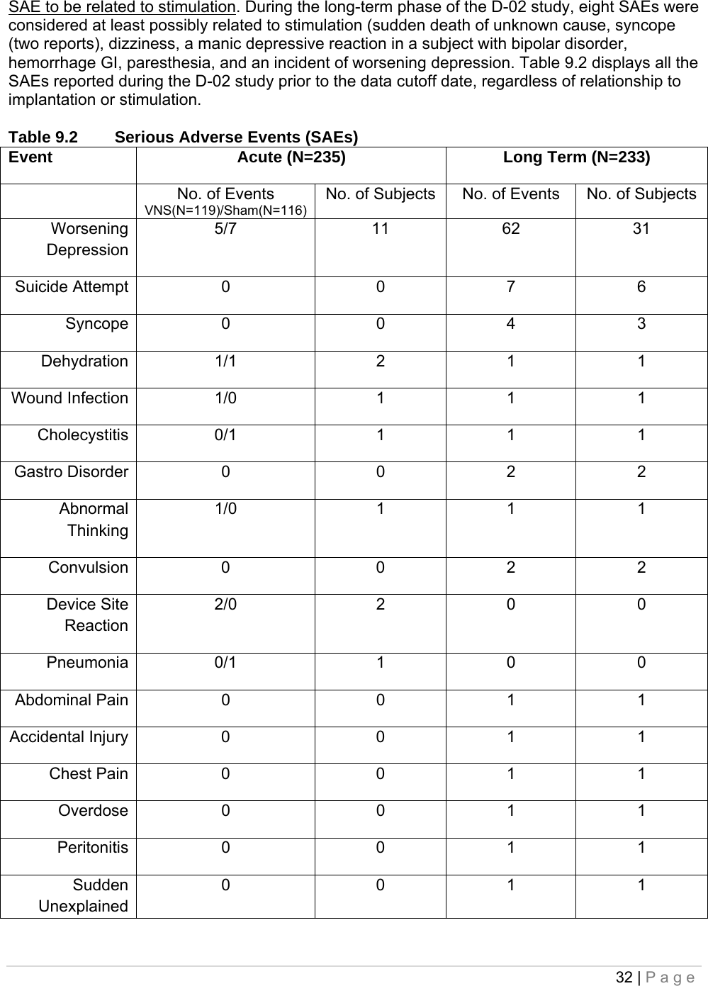
![31 | Page Paresthesia 26 (11.2%) 9 (4.3%) Laryngismus 23 (9.9%) 10 (4.8%) Pharyngitis 14 (6.0%) 11 (5.3%) Nausea 13 (5.6%) 4 (1.9%) Pain 13 (5.6%) 13 (6.2%) Headache 12 (5.2%) 8 (3.8%) Insomnia 10 (4.3%) 2 (1.0%) Palpitation 9 (3.9%) 6 (2.9%) Chest Pain 9 (3.9%) 4 (1.9%) Dyspepsia 8 (3.4%) 4 (1.9%) Hypertonia 6 (2.6%) 10 (4.8%) Hypesthesia 6 (2.6%) 2 (1.0%) Anxiety 5 (2.2%) 6 (2.9%) Ear Pain 5 (2.2%) 6 (2.9%) Eructation 4 (1.7%) 0 Diarrhea 4 (1.7%) 2 (1.0%) Dizziness 4 (1.7%) 3 (1.4%) Incision Site Reaction 4 (1.7%) 2 (1.0%) Asthma 4 (1.7%) 3 (1.4%) Device site reaction 4 (1.7%) 0 Device Site Pain 4 (1.7%) 2 (1.0%) Migraine Headache 4 (1.7%) 2 (1.0%) It is important to note that subjects often had comorbid illnesses and almost all study subjects were also receiving antidepressant and other drugs that could have contributed to these events. 9.2.1. Discontinuation due to adverse events By the time all continuing subjects in the pivotal (D-02) study had at least 1 year of VNS Therapy, 3% (8/235) of the subjects had discontinued VNS Therapy for an adverse event-related reason. The reasons for these eight discontinuations included one case each of suicide, implant-related infection necessitating device removal, hoarseness, lightheadedness, post-operative pain, chest and arm pain, sudden death (of unknown cause), and worsening depression (reported by the investigator as an adverse event rather than as lack of efficacy). 9.3. Serious Adverse Events (SAEs) 9.3.1. SAEs The SAEs described in this section are based on investigator reports from the pivotal (D-02) study from study initiation through the data cutoff date for submission; the data cutoff date included the entire period of evaluation for subjects who did not complete 12 months of VNS Therapy and included a minimum of 12 months of evaluation during VNS Therapy for all subjects who continued the study for 12 months or longer. During the pivotal (D-02) study, 12 SAEs were considered related to the implant procedure (wound infection, asystole, bradycardia, syncope, abnormal thinking, vocal cord paralysis, aspiration pneumonia, voice alteration, device site reaction [two reports], acute renal failure, and urinary retention). During the acute phase of the D-02 study, investigators did not report any](https://usermanual.wiki/MicroTransponder/10001001A/User-Guide-1847139-Page-31.png)
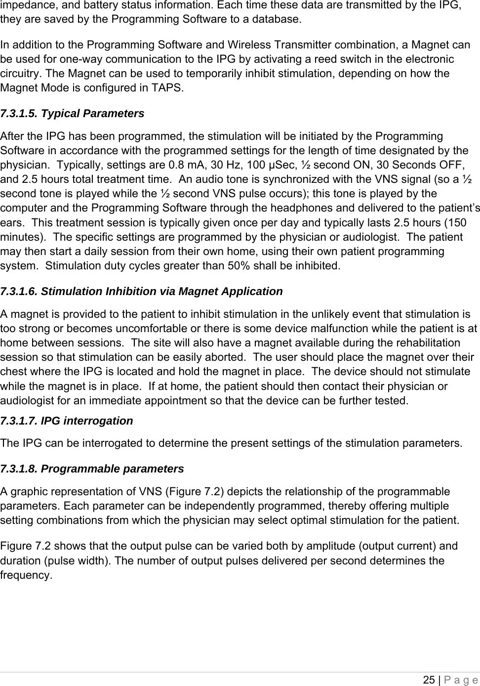
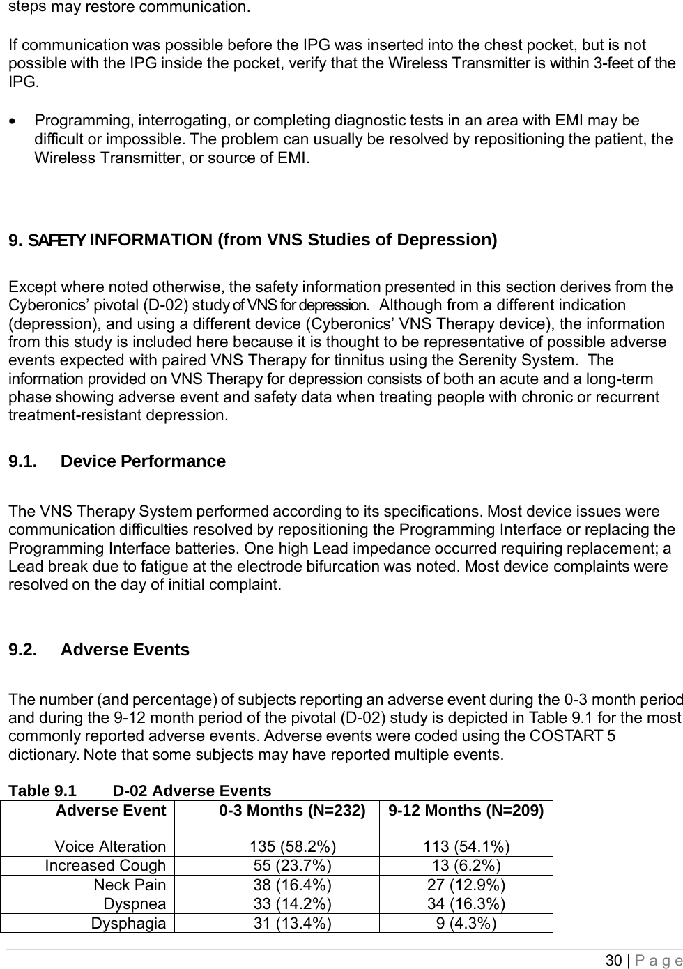
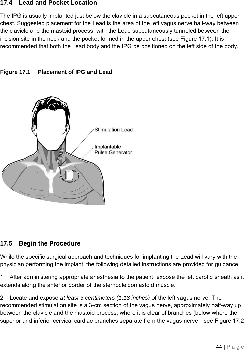
![42 | Page - Tie downs could potentially fall out of package, carefully remove the lead to maintain control of these. - Caution: Do not use the package if it has been exposed to extreme temperatures or if there is any indication of external damage or damage to the package seal. Instead, return it unopened to MicroTransponder. 17. RECOMMENDATIONS FOR IMPLANTATION In general, implantation of the Paired VNS Therapy Serenity System is similar to accepted practice for implantation of other implantable devices. The most novel portion of the surgery is the placement of the electrodes and the subcutaneous routing of the Lead connector and body over the clavicle. Although the surgical approach and techniques will vary with the preference of the implanting physician this part of the physician’s manual provides recommendations for implantation, along with a detailed description of the order of placement of the helical electrodes and the anchor tether and other essential steps. Critical to the long-term success of the implant are proper techniques both for the attachment of the electrodes and the anchor tether to the left vagus nerve, and for the provision of adequate strain relief below and above the sternocleidomastoid muscle. It is recommended that the Lead body be coiled and placed in the chest pocket underneath or to the side of the IPG; placement above the generator may cause damage to the lead body during generator replacement, and is therefore not recommended. Adequate exposure of the vagus nerve (>3 cm) facilitates placement of the electrodes on the nerve. Stretching the nerve or allowing it to dry during implantation may result in temporary swelling of the nerve. Constriction of the nerve or other nerve damage may result in vocal cord dysfunction. After the electrodes are placed on the nerve, the electrode-nerve interface impedance is tested by connecting the Lead directly to the IPG and performing a Lead Impedance Check. 17.1. Check the device and Input Patient Data To ensure proper device communication, using TAPS, check the IPG by communicating with it while still in the sterile package. [See the Paired VNS Therapy Serenity Non-Implantable Physician’s Manual for a detailed explanation or the Programming Software instruction card (handheld) for a quick reference.] Using TAPS, input the patient identification into the IPG. [See the Paired VNS Therapy Serenity Non-Implantable Physician’s Manual for a detailed explanation.]](https://usermanual.wiki/MicroTransponder/10001001A/User-Guide-1847139-Page-42.png)
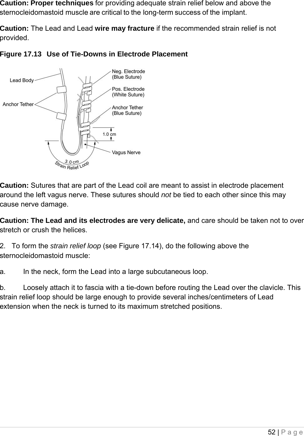
![51 | Page 3. Next, place the third helical electrode (with blue suture but without any electrode portion) around the nerve, following the same general steps as for the other two helices. 4. After all three helices have been coiled around the nerve, verify that the Lead body exits each helical electrode in the same direction and that the Lead bodies are aligned parallel to each other and to the nerve. The correct placement of the two helical electrodes and anchor tether is shown in Figure 17.12. Figure 17.12 Placement of Electrodes and Anchor Tether Caution: Sutures that are part of the Lead (embedded in the helices of the electrodes and anchor tether) are meant to assist in helical electrode placement around the vagus nerve. These sutures should not be tied to each other or around the nerve, since this may cause nerve damage. Caution: Proper techniques for attaching the electrodes and the anchor tether to the left vagus nerve are critical to the long-term success of the implant NOTE: Provide Proper Strain Relief After attaching the two electrodes and the anchor tether, form a strain relief bend and a strain relief loop in the Lead to provide adequate slack and allow for neck movement. 1. To form the strain relief bend [see Figure 17. 12 above], do the following: a. Form the Lead body into a 3-cm (1.18 in) strain relief bend with at least an additional 1 cm (.39 in) of Lead routed parallel to the nerve. The parallel portion can be placed in a pocket formed adjacent to the anchor tether. b. Loosely attach the 3-cm strain relief bend to the adjacent fascia with tie-downs and then route the Lead over the muscle. The first tie-down should be positioned laterally to the anchor tether (see Figure 17.13). Five tie-downs are provided in the Lead package.](https://usermanual.wiki/MicroTransponder/10001001A/User-Guide-1847139-Page-51.png)