Microchip Technology A09-0489 ATAVRRZ600 User Manual rz600
Atmel Norway AS ATAVRRZ600 rz600
Contents
- 1. user manual
- 2. User Manual
user manual
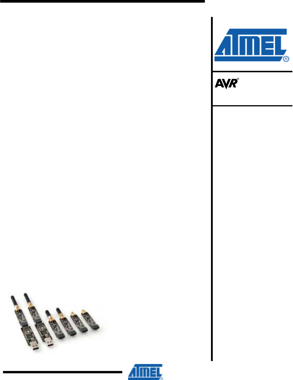
AVR600: RZ600 HW Manual
Features
• Contains the full selection of AT86RF family radio transceivers.
• Covers the 2.4GHz ISM band and 700, 800 and 900 MHz frequency bands.
• In total 3 pair of radio transceivers are available – one pair per radio
transceiver.
• Two AT32UC3A3256 based USB host boards are included
- Based on Atmel
®
AVR
®
UC3 core
- 80 Dhrystone MIPS and Draws Only 40 mA at 66 MHz
- Low, full and high speed USB compliant
- Ideal for PC to RF gateways, packet sniffers and network commissioning
tools
• On board ID chip for easy IEEE MAC address
• Stub antennas for all frequency bands
1 Introduction
The RZ600 kit is an evaluation kit for the Atmel AT86RF family of radio frequency
devices. The family contains the two 2.4 GHz device AT86RF230 and AT86RF231.
These are highly acclaimed networking devices within low power personal area
networks. In addition to this the world’s first IEEE 802.15.4 enabled sub gigahertz
radio is provided – the AT86RF212. With the kit you also receive two AVR UC3
based host nodes that can be used to evaluate a point to point network connection.
That being said; the RZ600 radio boards sport an Atmel standardized 10-pin
connector that will enable the RF boards to be connected to any AVR
microcontroller. A wide range of the standard Atmel AVR design tools have the
host end of the standardized 10-pin connector – so as a customer you will be able
to evaluate Atmel radio transceivers in virtually any application segment.
The RZ600 kit enables RF4CE, IEEE 802.15.4, ZigBee
®
and 6lowPAN network
technologies to run on the full Atmel portfolio of low power AVR microcontrollers.
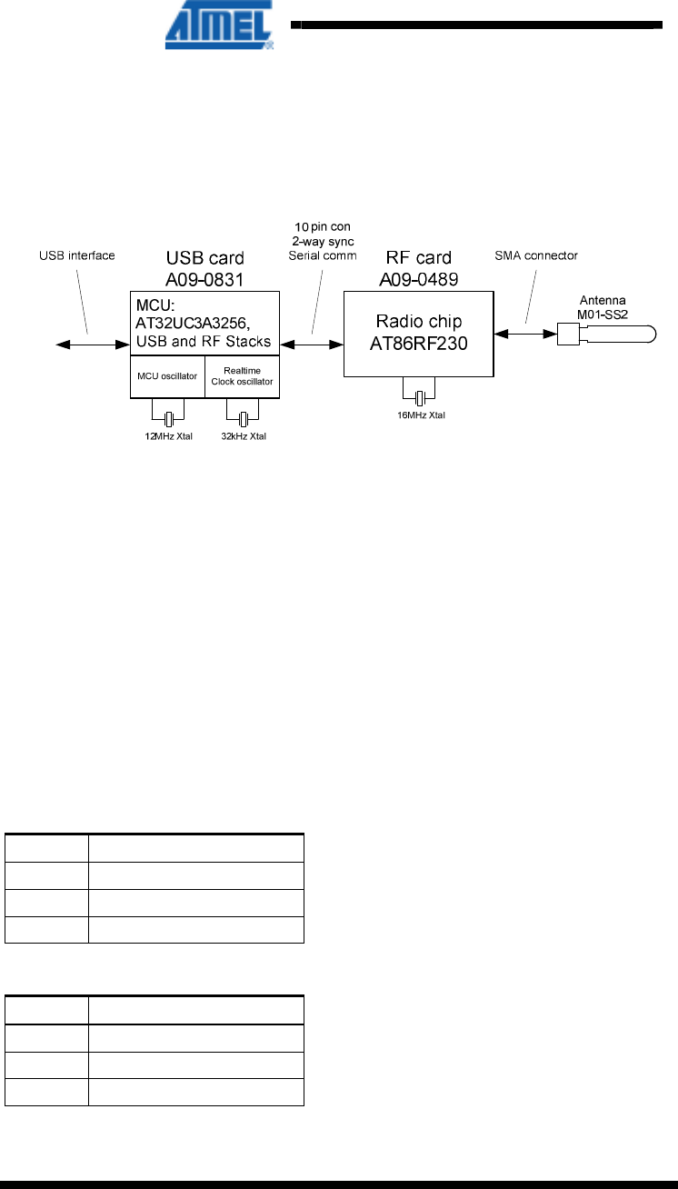
Figure 1-1. RZ600 HW Overview
Microcontrollers
Application Note
Rev. 8293-AVR-02/10

2
AVR600
8293-AVR-02/10
2 Related Items
AVR32 Studio (Atmel’s free IDE)
http://www.atmel.com/dyn/products/tools_card.asp?tool_id=4116
GNU Toolchain (Atmel’s free Compiler and Utilities)
http://www.atmel.com/dyn/products/tools_card.asp?tool_id=4118
JTAGICE mkII (On-chip programming and debugging tool)
http://www.atmel.com/dyn/products/tools_card.asp?tool_id=3353
AVR ONE! (On-chip programming and debugging tool)
http://www.atmel.com/dyn/products/tools_card.asp?tool_id=4279
3 Overview
This section gives an overview of the RZ600 kit from a system perspective as well as
what the kit contains and its minimum requirements. A set of condensed instructions
are then given on how to get the evaluation application for the kit up and running in
the shortest time possible.
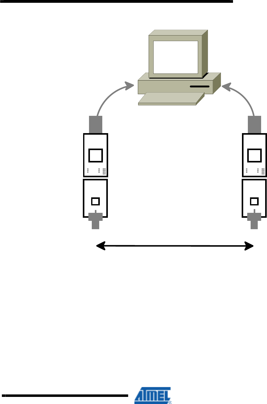
Figure 3-1 shows how the two processor boards paired with the radio frequency
boards also available in the kit can form a wireless peer to peer data connection over
USB. The application that is pre programmed by Atmel on the AT32UC3A3256 is
indeed such a USB to RF gateway.
AVR600
3
8293-AVR-02/10
Figure 3-1 RZ600 used in conjuntion with PC
RF Link
RZ600 Processor Board
RZ600 RF Board
3.1 Kit Contents
The RZ600 kit contains the following pieces of hardware:
• 2 pcs. AT86RF230 radio cards: miniature carrier board with the AT86RF230 radio
transceiver mounted, SMA antenna connector, one wire ID chip and Atmel
standard 10-pin connector.
• 2 pcs. AT86RF231 radio cards: miniature carrier board with the AT86RF231 radio
transceiver mounted, SMA antenna connector, one wire ID chip and Atmel
standard 10-pin connector.
• 2 pcs. AT86RF212 radio cards: miniature carrier board with the AT86RF212 radio
transceiver mounted, SMA antenna connector, one wire ID chip and Atmel
standard 10-pin connector.
• 2 pcs. AVR UC3 based processor cards: usb dongle form factor board with
AT32UC3A3256 processor mounted, LEDs, UART connection and host side
Atmel standard 10-pin connector.
• 2 pcs. 2.4GHz SMA stub antenna. These are shared between the AT86RF230
and AT86RF231 radio transceivers.
4
AVR600
8293-AVR-02/10
• 2 pcs. Sub gigahertz SMA stub antenna. Used with the AT86RF212 radio
transceiver.
• 2 pcs. Bag with wires and squid cable: The squid cable fits the radio frequency
boards and will enable wiring to a hardware that does not contain the standard
Atmel 10-pin accessory header.
• 1 pcs. Technical Library CD
3.2 System Requirements
Table 3-1 contains the minimum system requirements for the RZ600 kit when
connected to a PC for application development on the AT32UC3A3256
microcontroller.
Table 3-1. Minimum System Requirements
Parameter Value Comment
Hardware
PC/CPU Intel
®
Pentium III or
better, 800 MHz
PC/RAM 128 MBytes
PC/Video 1024x768, SVGA
PC/ Hard disk free space 200 Mbytes
On-Chip Debugger and
programmer
AVR JTAGICE mkII or
AVRONE!
The AVR JTAGICE mkII or
AVRONE! is needed if the user
wishes to debug and do custom
application development.
Software
Operating System Windows
®
2000/XP/Vista
IDE AVR32 Studio or IAR
Embedded Workbench
AVR32 Studio with compiler
utilities is required for
reprogramming the processor
board and for application
development.
3.3 Quick Start Guide
To following sequence is suggested when testing the evaluation application the
RZ600 kit:
1. Unpack the kit and verify contents
2. Identify the processor boards and select two radio frequency boards with the same radio
transceiver mounted. It is suggested to do this even though there are two different radio
transceivers for the 2.4GHz band that are fully compatible with each other: AT86RF230 vs.
AT86RF231.
3. Mount a radio frequency board to each of the processor boards
4. Insert the assembly into a free USB port on the computer.
5. Let the devices enumerate – they should become available as two CDC virtual COM ports.
6. Open two terminal windows and start typing. Verify that the text in the two terminals is the
same.

AVR600
5
8293-AVR-02/10
4 Hardware Description
This chapter walks through the different pieces of hardware that you will find in the
RZ600 kit in greater detail.
4.1 Radio Frequency Board
A total of six radio frequency boards included in the kit, two boards per radio
transceiver:
• AT86RF230: First generation 2.4GHz ISM band radio transceiver from Atmel.
• AT86RF231: Second generation 2.4GHz ISM band radio transceiver with front
ends for antenna diversity and external power amplifier and encryption
accelerators.
• AT86RF212: 868/915MHz ISM band long range radio transceiver with front end
for external power amplifier and encryption accelerators.
The radio transceiver share the same printed circuit board with slightly different
component values mounted for each of them. See Figure 4-2 for full schematics of
the radio frequency board.
6
AVR600
8293-AVR-02/10
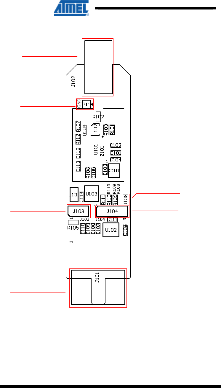
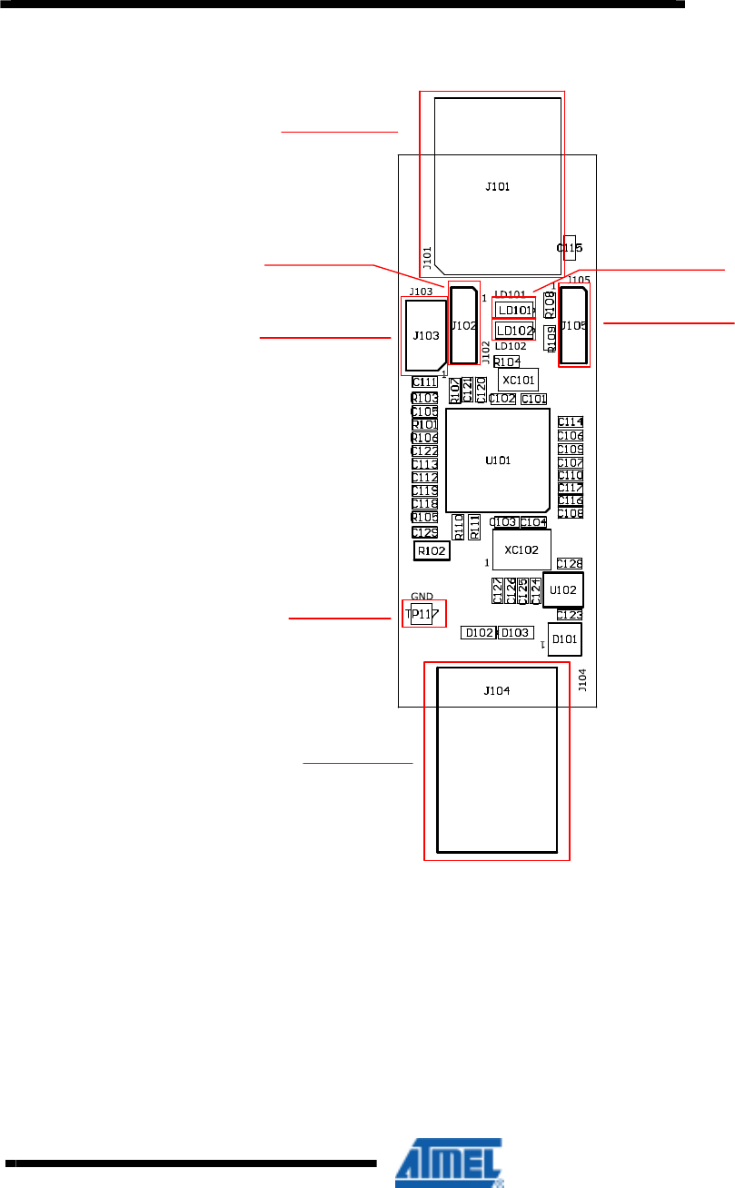
Figure 4-1 Radio Frequency Board Overview
GND
SMA con
10 pin con
Current sens MISC signal
MISC signal
selector
4.1.1 Connectors
There are two main connectors on the board; one is the female SMA antenna
connector and in the opposite direction of the board is a 10-pin dual row header. See
Table 4-1 for pinout of this header.
AVR600
7
8293-AVR-02/10
Table 4-1. Radio Frequency 10-pin header
Pin Name Name Pin
1 Reset
Misc 2
3 Interrupt
Sleep Transmit 4
5 Chip Select
MOSI 6
7 MISO
SCK 8
9 GND
VCC (1.8 – 3.6V) 10
There are also two single row headers on the board:
• J103 (Not mounted): Two pin header that can be soldered in to do current
measurement with an ampere meter. R105 must be unsoldered to enable this
feature.
• J104 (Not mounted): Three pin header that can be soldered in to access the
auxiliary (Miscellaneous) signals from the radio transceiver.
4.1.2 Crystal
A high accuracy 16MHz crystal is mounted and used by the radio transceiver for
carrier frequency generation.
4.1.3 RF Front End
Since the output from the radio transceiver itself is a balanced signal pair, a balun is
needed to transform into a 50Ohm single ended signal fed to the SMA connector.
Johanson Technology provides two pin compatible baluns for the AT86RF230,
AT86RF231 and AT86RF212:
• 2450FB15L0001: 2.45 GHz filter balun optimized for AT86RF230 and
AT86RF231.
• 0896FB15A0100: Sub gigahertz filter balun combination optimized for
AT86RF212.
8
AVR600
8293-AVR-02/10
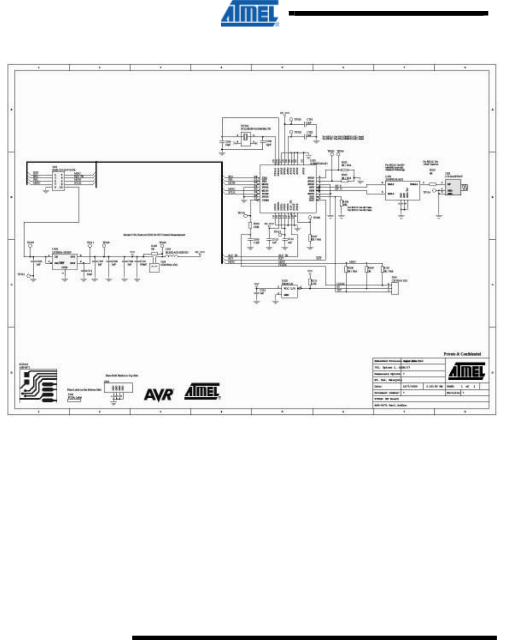
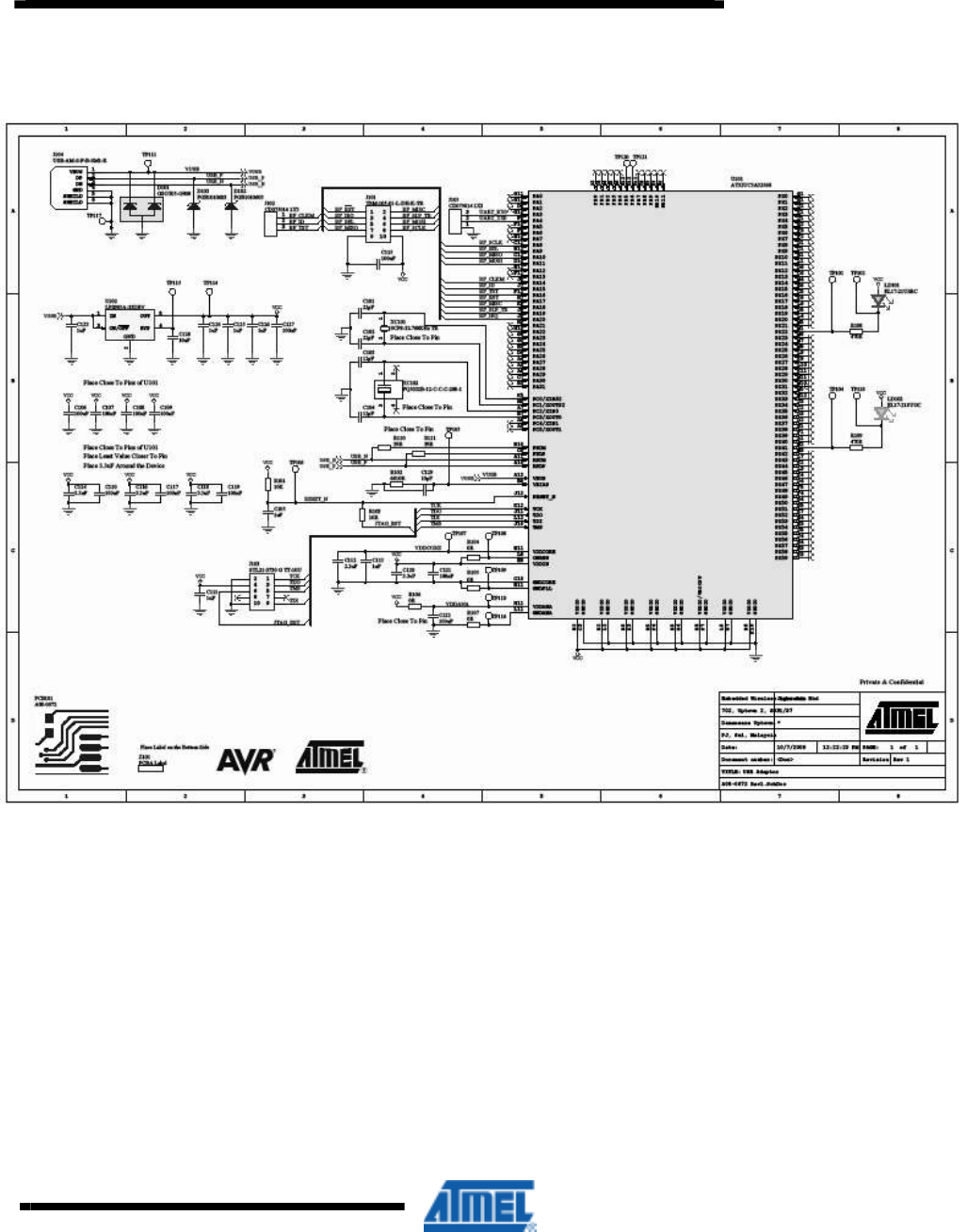
Figure 4-2 Radio Frequency Board
4.2 ATAVR32UC3 Processor Board
There are two AT32UC3A3256 based processor board in the kit. They run the
protocol stack to control the radio transceiver as well as providing USB full and high
speed USB connection (up to 480Mbps). Figure 4-3 shows an overview of some of
the main components and their placement.
AVR600
9
8293-AVR-02/10
Figure 4-3 Processor Board Overview
10 pin con
USB
GND
JTAG ISP
Serial port
MISC signal
LED
indicators
4.2.1 Processor
The AT32UC3A3256 flash microcontroller is designed for exceptionally high data
throughput with Hi-Speed USB OTG, SD/ SDIO card, Multi-Level-Cell (MLC) NAND
flash with ECC and SDRAM interfaces. Designed with the multi-layered 32-bit AVR
databus, 128 KB on-chip SRAM with triple high speed interfaces, and multi-channel
Peripheral and memory to memory DMA controller, the AT32UC3A3256 offers
outstanding data throughput. The device is reprogrammable through the 10 pin JTAG
connector on the board.
4.2.2 Clocks
There are two clocks available on the processor board:
10
AVR600
8293-AVR-02/10
• 12 MHz: The crystal is required as input to the internal PLL of the AT32UC3A3256
to generate the base frequency for the full and high speed USB mode.
• 32 kHz: Used as input source for the real time clock.
Figure 4-4 Clock Locations
4.2.3 LEDs
Two LEDs are available connected to the AT32UC3A3256’s pins PX22 and PX41.
These are turned on by sinking current through the pin – logic low while acting as an
input.
4.2.4 Headers
Four headers are available on the processor board:
• 10-pin header (J101): Interface for the radio frequency board.
• Three pin header RF (J102 – not mounted): Auxiliary signals that can be
patched in from the same three pin header on the radio frequency board. See
Table 4-2 for pinout.
• JTAG Interface (J103 – not mounted): Standard Atmel JTAG header.
• Three pin header UART (J105 – not mounted): See Table 4-3 for pinout.
Table 4-2. J102 3-pin RF Auxiliary header
Pin Name
J102-1 Clock Output
J102-2 ID Chip
J102-3 Test pin – AT86RF230
Table 4-3. J105 3-pin UART header
Pin Name
J105-1 GND
J105-2 UART TX
J105-3 UART RX
AVR600
11
8293-AVR-02/10
Figure 4-5 Processor Board
4.3 Antennas
There are two different antennas (SMA stub type) available in the RZ600 kit
• Long Type: This is used only in conjunction with the AT86RF212 radio
transceiver.
• Short Type: This antenna is made for the 2.4GHz frequency band and can be
used either on the AT86RF230 or AT86RF231 radio transceiver.
The antennas should be screwed onto the respective radio frequency board and
gently tightened.
12
AVR600
8293-AVR-02/10
4.4 Cables
There are two different cable types available in the RZ600 kit
• Squid Cable:
• Single Wire:
5 Connecting Radio Frequency Board to a Custom Board
The radio frequency boards found as part of this kit can be used stand alone as well
as in conjunction with the processor board. Table 4-1 shows the pinout of the
standardized 10-pin bus that is defined between the two unit. However, it is possible
to add the radio frequency board to any routing as long as the required signals are
available. This is possible due to the radio frequency board being able to be mounted
on the squid cable included in this kit. With this squid cable it is possible to route all
10 signals down onto a custom hardware. The reminder of this chapter shows a few
examples on how to wire these signals.
5.1 Default Supported Kits
Besides from being used on the processor boards the radio frequency board can be
attached to wide range of Atmel evaluation and starter kits. The following kits are
supported directly. If you do not find your preferred kit here, please take a look at
section 5.2.
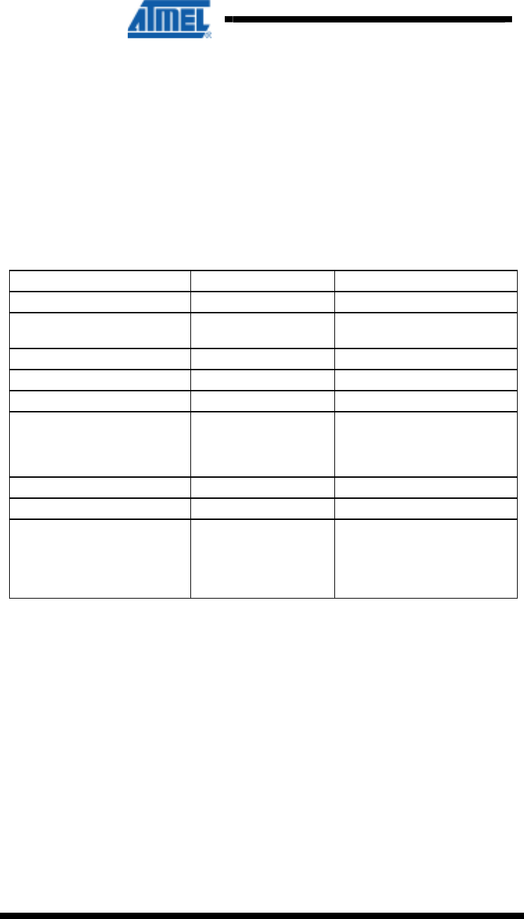
Table 5-1. Plug and Play Kits
Kit Name Comment
STK600
- Any ATxmega device Any of the digital ports can be used.
- ATmega164/324/644/1284P
STK500
- ATmega164/324/644/1284P
XPLAIN Any of the digital ports can be used.
EVK1104 Connect to WLESS header.
EVK1105 Connect to WLESS header.
5.2 Squid Cable
There are two squid cables (10pin male header to single wires) included in the kit.
The intended use of this special cable assembly is to plug the radio frequency board
onto it, and connect the ten single wires to any hardware platform that does not have
the standard auxiliary connector available.
Table 5-2. Squid Cable Pinout
PIN
PIN
Pin 1 (Brown): Reset
Pin 2 (Red): Miscellaneous
Pin 3 (Orange): Interrupt
Pin 4 (Yellow): Sleep Transmit
Pin 5 (Green): Chip Select
Pin 6 (Blue): Master Out Slave In
AVR600
13
8293-AVR-02/10
PIN
PIN
Pin 7 (Purple): Master In Slave Out
Pin 8 (Grey): SPI Clock
Pin 9 (White): Ground
Pin 10 (Black): Vcc
5.3 Example AVR32: EVK1100
Intentionally left blank.
5.4 Example ARM7: AT91SAM7X-EK
Intentionally left blank.
6 Firmware
Table 6-1. Firmware Layout
Path File Comment
/Applications Parent folder for kit applications
/Applications/TAL_Examples/Wireless_UART Parent folder for wireless UART application
/Applications/TAL_Examples/Wireless_UART/Src Source Folder
/PAL Processor Abstraction Layer
/PAL/AVR32 Parent folder for AVR32 processor specific code
/PAL/AVR32/Generic/Inc Generic include files shared by all AVR32 devices.
/PAL/AVR32/Generic/Src Generic source code shared by all AVR32 devices.
/PAL/AVR32/UC3A3256 Parent folder for all AT32UC3A3256 specific code
/PAL/AVR32/UC3A3256/Boards/RZ600 Board specific code for the RZ600 kit
/PAL/AVR32/UC3A3256/Inc Include files for the processor code
/PAL/AVR32/UC3A3256/Src Source files for the processor specific code
/TAL Transceiver Abstraction Layer
/TAL/AT86RF212/Inc Include files specific to the AT86RF212 radio transceiver
/TAL/AT86RF212/Src Source files specific to the AT86RF212 radio transceiver.
/TAL/AT86RF230B/Inc Include files specific to the AT86RF230 radio transceiver
/TAL/AT86RF230B/Src Source files specific to the AT86RF230 radio transceiver.
/TAL/AT86RF231/Inc Include files specific to the AT86RF231 radio transceiver
/TAL/AT86RF231/Src Source files specific to the AT86RF231 radio transceiver.
/Resources Common resources used by all layers
/Resources/Buffer_Management/Inc
/Resources/Buffer_Management/Src
/Resources/Queue_Management/Inc
/Resources/Queue_Management/Src

14
AVR600
8293-AVR-02/10
7 Getting Started
This chapter describes how to get started with the RZ600 kit and run the demo
application in the most efficient way. Read section for section sequentially and follow
the directions carefully. The quick start guide assumes that the requirements in
section 3.2 are fulfilled.
7.1 Kit Unpacking
1. Open the box and verify that all items are present as outlined in section 3.1.
2. Locate the two processor boards and select a pair of radio transceivers to test –
they should be of the same type.
3. Mount the radio frequency board onto the processor boards 10-pin connector.
Make sure that pin 1 on both boards aligns.
4. Attach any of the auxiliary signals between the two units using the single wires.
7.2 USB Enumeration
1. Connect one of the board assemblies to you PC and let it start USB enumeration
process.
2. The first time this is done, the CDC driver will have to be installed. A “Found new
hardware wizard” will pop up. Select “No, not this time” and next.
3. Select “Install from a list or specific location (Advanced). Click next. Select “Include
this location in the search:”. Select the following folder:
/PAL/AVR32/UC3A3256/Boards
4. Click finish.
5. Verify what COM port that was assigned to the USB device. This can be done from
the Control Panel under the start menu. Select Administrative Tools from the menu
and then click the Computer Management. Now click on the Computer
Management item – and look under the Ports (COM & LPT) from the list. A new
COM port should be available
6. Repeat step 1 to 5 for the second board assembly.
7.3 Run the Example Application
Any terminal application can be used to connect to the COM ports, this section shows
how to do this with HyperTerminal.
1. From the start menu select All Programs, Accessories, Communications and finally
HyperTerminal.
2. Type in a name for the connection
3. A “Connect To” dialog will appear. Make sure to select the correct COM port.
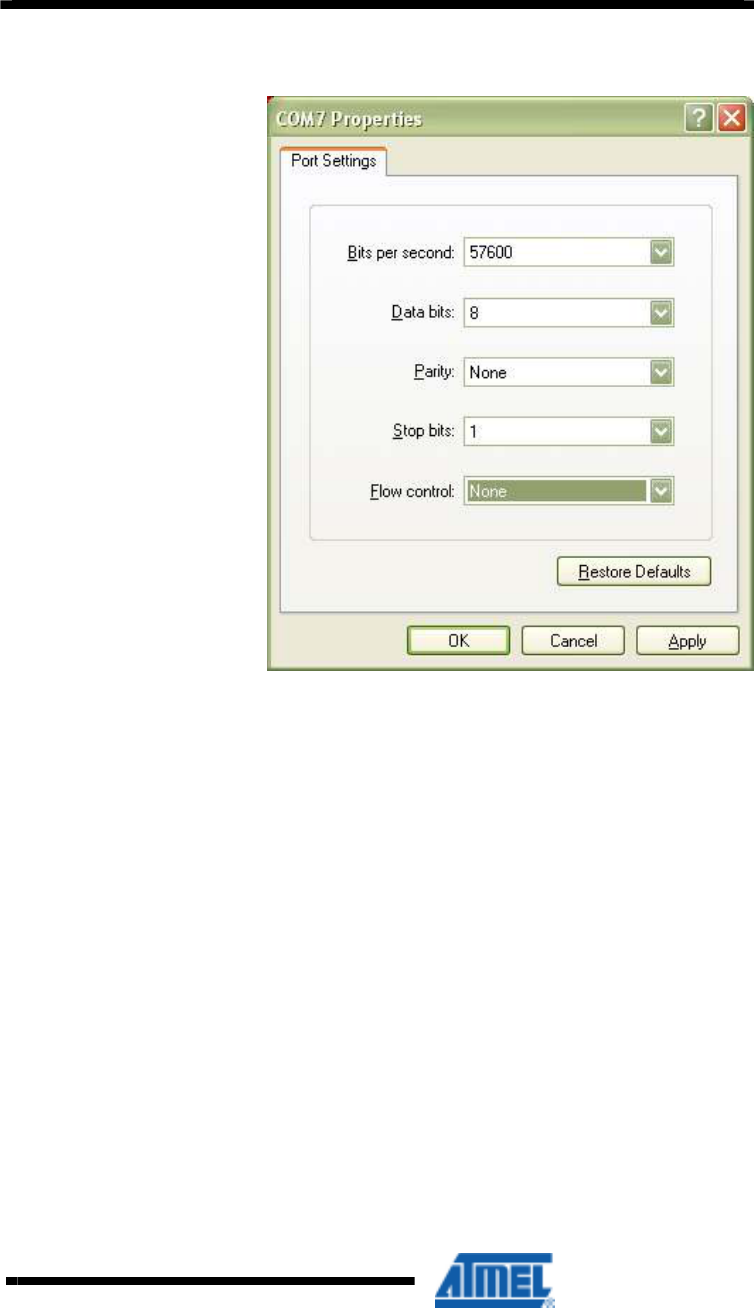
4. Press the Configure button and use the setting shown in Figure 7-1. Click the OK
button twice.
5. You now have a terminal window ready to use
6. Repeat steps 1 to 5 for the second board assembly.
7. Type characters in one of the terminals and verify that they are conveyed over to
the second terminal.
AVR600
15
8293-AVR-02/10
Figure 7-1 COM Port Settings
7.4 Install Software and Test
This step is only required for doing application development on the RZ600 kit.
1. Install GNU Toolschain – see section 2.
2. Install AVR32 Studio – see section 2.
3.
7.5 Programming the Example Application
This step is only required for doing application development on the RZ600 kit.
1. Connect either a JTAGICE mkII or AVRONE! to your computer.
2. Go through the driver installation. Let the PC select the best USB driver for the
attached debugger. The AVR USB program takes care of this in the background.
3. Solder the 50 mil 10-pin connector to one of the processor board.
4. Mount a 100mil to 50mil adapter to the debugger and connect the probe to the
freshly soldered connector.
5. Use AVR32 Studio or IAR Embedded Workbench
®
to develop and debug
programs.

16
AVR600
8293-AVR-02/10
8 Appendix
8.1 FCC Statements
8.1.1 Equipment usage
This equipment is for use by developers for evaluation purposes only and must not be
incorporated into any other device or system.
8.1.2 Compliance Statement (Part 15.19)
These devices comply with Part 15 of the FCC Rules. Operation is subject to the
following two conditions:
1. These devices may not cause harmful interference, and
2. These devices must accept any interference received, including interference that
may cause undesired operation.
8.1.3 Warning (Part 15.21)
Changes or modifications not expressly approved by Atmel Norway could void the
user’s authority to operate the equipment.
8.1.4 Compliance Statement (Part 15.105(b))
This equipment has been tested and found to comply with the limits for a Class B
digital device, pursuant to Part 15 of the FCC Rules. These limits are designed to
provide reasonable protection against harmful interference in a residential installation.
This equipment generates uses and can radiate radio frequency energy and, if not
installed and used in accordance with the instructions, may cause harmful
interference to radio communications. However, there is no guarantee that
interference will not occur in a particular installation. If this equipment does cause
harmful interference to radio or television reception, which can be determined by
turning the equipment off and on, the user is encouraged to try to correct the
interference by one or more of the following measures:
• Reorient or relocate the receiving antenna.
• Increase the separation between the equipment and receiver.
• Connect the equipment into an outlet on a circuit different from that to which the
receiver is connected.
• Consult the dealer or an experienced radio/TV technician for help.
8.1.5 FCC IDs
• A09-0489 AT86RF230 VW4A09-0489
• A09-0490 AT86RF 231 VW4A09-0490
• A09-0491 AT86RF 212 VW4A09-0491

AVR600
17
8293-AVR-02/10
EVALUATION BOARD/KIT IMPORTANT NOTICE
This evaluation board/kit is intended for use for FURTHER ENGINEERING,
DEVELOPMENT, DEMONSTRATION, OR EVALUATION PURPOSES ONLY. It is
not a finished product and may not (yet) comply with some or any technical or legal
requirements that are applicable to finished products, including, without limitation,
directives regarding electromagnetic compatibility, recycling (WEEE), FCC, CE or UL
(except as may be otherwise noted on the board/kit). Atmel supplied this board/kit
“AS IS,” without any warranties, with all faults, at the buyer’s and further users’ sole
risk. The user assumes all responsibility and liability for proper and safe handling of
the goods. Further, the user indemnifies Atmel from all claims arising from the
handling or use of the goods. Due to the open construction of the product, it is the
user’s responsibility to take any and all appropriate precautions with regard to
electrostatic discharge and any other technical or legal concerns.
EXCEPT TO THE EXTENT OF THE INDEMNITY SET FORTH ABOVE, NEITHER
USER NOR ATMEL SHALL BE LIABLE TO EACH OTHER FOR ANY INDIRECT,
SPECIAL, INCIDENTAL, OR CONSEQUENTIAL DAMAGES.
No license is granted under any patent right or other intellectual property right of
Atmel covering or relating to any machine, process, or combination in which such
Atmel products or services might be or are used.
Mailing Address: Atmel Corporation, 2325 Orchard Parkway, San Jose, CA 95131

8293-AVR-02/10
Disclaimer
Headquarters International
Atmel Corporation
2325 Orchard Parkway
San Jose, CA 95131
USA
Tel: 1(408) 441-0311
Fax: 1(408) 487-2600
Atmel Asia
Unit 1-5 & 16, 19/F
BEA Tower, Millennium City 5
418 Kwun Tong Road
Kwun Tong, Kowloon
Hong Kong
Tel: (852) 2245-6100
Fax: (852) 2722-1369
Product Contact
Atmel Europe
Le Krebs
8, Rue Jean-Pierre Timbaud
BP 309
78054 Saint-Quentin-en-
Yvelines Cedex
France
Tel: (33) 1-30-60-70-00
Fax: (33) 1-30-60-71-11
Atmel Japan
9F, Tonetsu Shinkawa Bldg.
1-24-8 Shinkawa
Chuo-ku, Tokyo 104-0033
Japan
Tel: (81) 3-3523-3551
Fax: (81) 3-3523-7581
Web Site
http://www.atmel.com/
Technical Support
avr@atmel.com
Sales Contact
www.atmel.com/contacts
Literature Request
www.atmel.com/literature
Disclaimer: The information in this document is provided in connection with Atmel products. No license, express or implied, by estoppel or otherwise, to any
intellectual property right is granted by this document or in connection with the sale of Atmel products. EXCEPT AS SET FORTH IN ATMEL’S TERMS AND
CONDITIONS OF SALE LOCATED ON ATMEL’S WEB SITE, ATMEL ASSUMES NO LIABILITY WHATSOEVER AND DISCLAIMS ANY EXPRESS, IMPLIED
OR STATUTORY WARRANTY RELATING TO ITS PRODUCTS INCLUDING, BUT NOT LIMITED TO, THE IMPLIED WARRANTY OF MERCHANTABILITY,
FITNESS FOR A PARTICULAR PURPOSE, OR NON-INFRINGEMENT. IN NO EVENT SHALL ATMEL BE LIABLE FOR ANY DIRECT, INDIRECT,
CONSEQUENTIAL, PUNITIVE, SPECIAL OR INCIDENTAL DAMAGES (INCLUDING, WITHOUT LIMITATION, DAMAGES FOR LOSS OF PROFITS,
BUSINESS INTERRUPTION, OR LOSS OF INFORMATION) ARISING OUT OF THE USE OR INABILITY TO USE THIS DOCUMENT, EVEN IF ATMEL HAS
BEEN ADVISED OF THE POSSIBILITY OF SUCH DAMAGES. Atmel makes no representations or warranties with respect to the accuracy or completeness of the
contents of this document and reserves the right to make changes to specifications and product descriptions at any time without notice. Atmel does not make any
commitment to update the information contained herein. Unless specifically provided otherwise, Atmel products are not suitable for, and shall not be used in,
automotive applications. Atmel’s products are not intended, authorized, or warranted for use as components in applications intended to support or sustain life.
© 2010 Atmel Corporation. All rights reserved. Atmel®, Atmel logo and combinations thereof, AVR®, AVR Studio®, STK® and others, are
the registered trademarks or trademarks of Atmel Corporation or its subsidiaries. Windows® and others are registered trademarks or
trademarks of Microsoft Corporation in U.S. and/or other countries. Other terms and product names may be trademarks of others.