Microchip Technology A092353 ATREB215-XPRO-A User Manual
Atmel Norway AS ATREB215-XPRO-A Users Manual
Users Manual
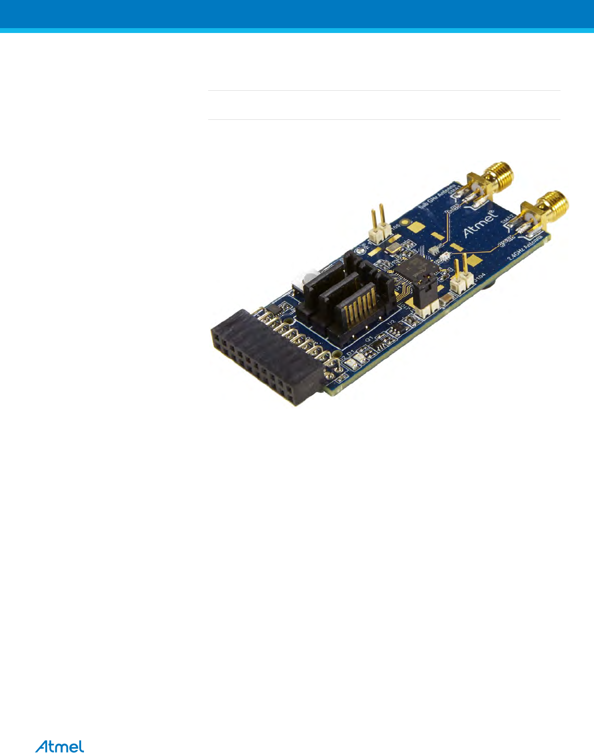

ATREB215-XPRO-A Test User Manual
2
Table of Contents
1. Introduction ........................................................................................ 3
Scope ………………………………………………………………………………………….3
2. Hardware Setup ................................................................................. 4
3. Software Setup .................................................................................. 4
4. Software Installation ........................................................................... 4
5. Hardware and Driver Installation ........................................................ 5
6. Programming SAM4L Xpro board to connect with ATREB215-Xpro-A 6
7. Performance Analyzer ........................................................................ 8
8. Tx Test (Single node / Continuous Transmission) for Sub-1GHz CE
Testing …………………………………………………………………......9
8.1 Tx Test: MR-FSK operating mode #1, 50kbit/s, 14dBm .................................. 11
8.2 Tx Test: OFDM Option 4, MCS3, 14dBm ........................................................ 12
8.3 Tx Test: O-QPSK RateMode 0, 14dBm .......................................................... 13
8.4 Tx Test: O-QPSK RateMode 3, 14dBm .......................................................... 14
9. Tx Test (Single node / Continuous Transmission) for Sub-1GHz FCC
Testing …………………………………………………………………….15
9.1 Tx Test: MR-FSK operating mode #1, 50kbit/s, 14dBm .................................. 15
9.2 Tx Test: OFDM Option 1, MCS3, 14dBm ........................................................ 16
9.3 Tx Test: O-QPSK RateMode 0, 14dBm .......................................................... 17
10. Tx Test for 2.4GHz Band (Single node / Continuous Transmission
(CW/PRBS)) ..................................................................................... 18
10.1 Tx Test - Legacy O-QPSK, 14dBm ................................................................. 20
10.2 Tx Test – MR-FSK operating mode #1, 50kbit/s, 14dBm ................................ 21
10.3 Tx Test - OFDM Option 1, MCS3, 14dBm ....................................................... 22
10.4 Tx Test - OFDM Option 2, MCS3, 14dBm ....................................................... 23
11. Tx-Rx Test (Transmit and Receive test) for Sub-1GHz CE Testing .. 24
9.1 Tx-Rx Test: MR-FSK operating mode #1, 50kbit/s, 14dBm ............................ 27
9.2 Tx-Rx Test: OFDM Option 4, MCS3, 14dBm .................................................. 28
9.3 Tx-Rx Test: OQPSK, RateMode 0, 14dBm ..................................................... 29
9.4 Tx-Rx Test: OQPSK, RateMode 3, 14dBm ..................................................... 30
12. Tx-Rx Test (Transmit and Receive test) for Sub-1GHz FCC Testing 30
12.1 Tx-Rx Test: MR-FSK operating mode #1, 50kbit/s, 14dBm ............................ 30
12.2 Tx-Rx Test: OFDM Option 1, MCS3, 14dBm .................................................. 31
12.3 Tx-Rx Test: OQPSK, RateMode 0, 14dBm ..................................................... 32
13. Tx-Rx Test for 2.4GHz Band (Transmit and Receive test) ................ 33
9.5 Rx Test – Legacy O-QPSK, 14dBm ................................................................ 35
9.6 Rx Test: MR-FSK operating mode #1, 50kbit/s, 14dBm .................................. 36
9.7 Rx Test - OFDM Option 1, MCS3, 14dBm ...................................................... 37
9.8 Rx Test - OFDM Option 2, MCS 3, 14dBm ..................................................... 38
ATREB215-XPRO-A Test User Manual
4
2. Hardware Setup
1. ATREB215-XPRO-A Boards - 2 Nos
2. SAM4L-XplainedPro Boards - 2 Nos
3. micro USB cable - 2 Nos
4. 2.4GHz Stubby Antenna (M01-SS2) - 2No
5. 1/4 wave whip Antenna (CTA 868/0/WS/SM/H1) -2No
Note: SMA cables not included in the box
3. Software Setup
1. Atmel Studio 6.2 (no need to install again if it is already available in Test PC)
2. SAM4L-XplainedPro Drivers - Installed automatically
4. Software Installation
Note: If Atmel Studio 6.2 is already available in Test PC, jump to step 5 in this section and install wireless composer
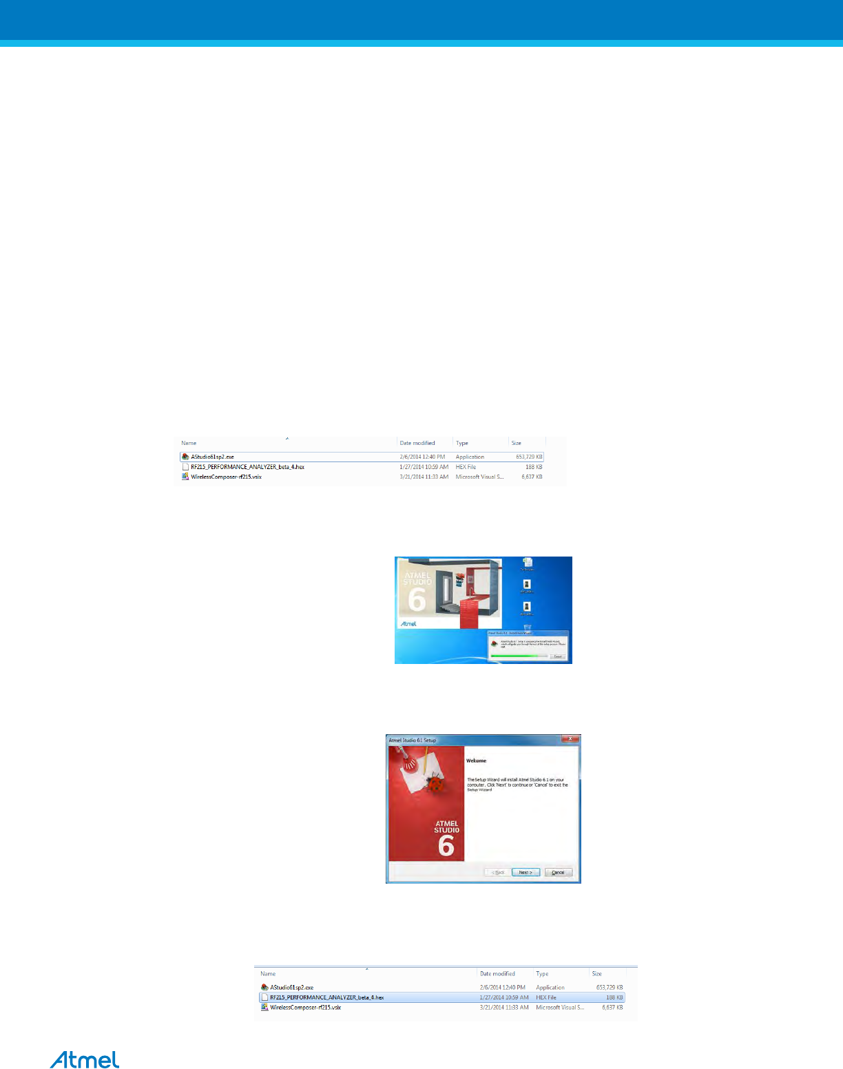
1. Open the DVD containing the Atmel Studio 6.2 Software package.
2. Click the AStudio61sp2.exe icon to launch Atmel Studio Installation.
Figure 3: Atmel Studio Installer
3. Now Atmel Studio will begin the installation
Figure 4: Atmel Studio Installation
4. Follow the on-screen instructions to complete the installation
Figure 5: Atmel Studio Installation
5. Next install the Wireless Composer extension by clicking the wireless-composer-vsix-stable icon found in
the DVD as shown in the following figure.
Figure 6: Wireless Composer Installation
ATREB215-XPRO-A Test User Manual
5
5. Hardware and Driver Installation
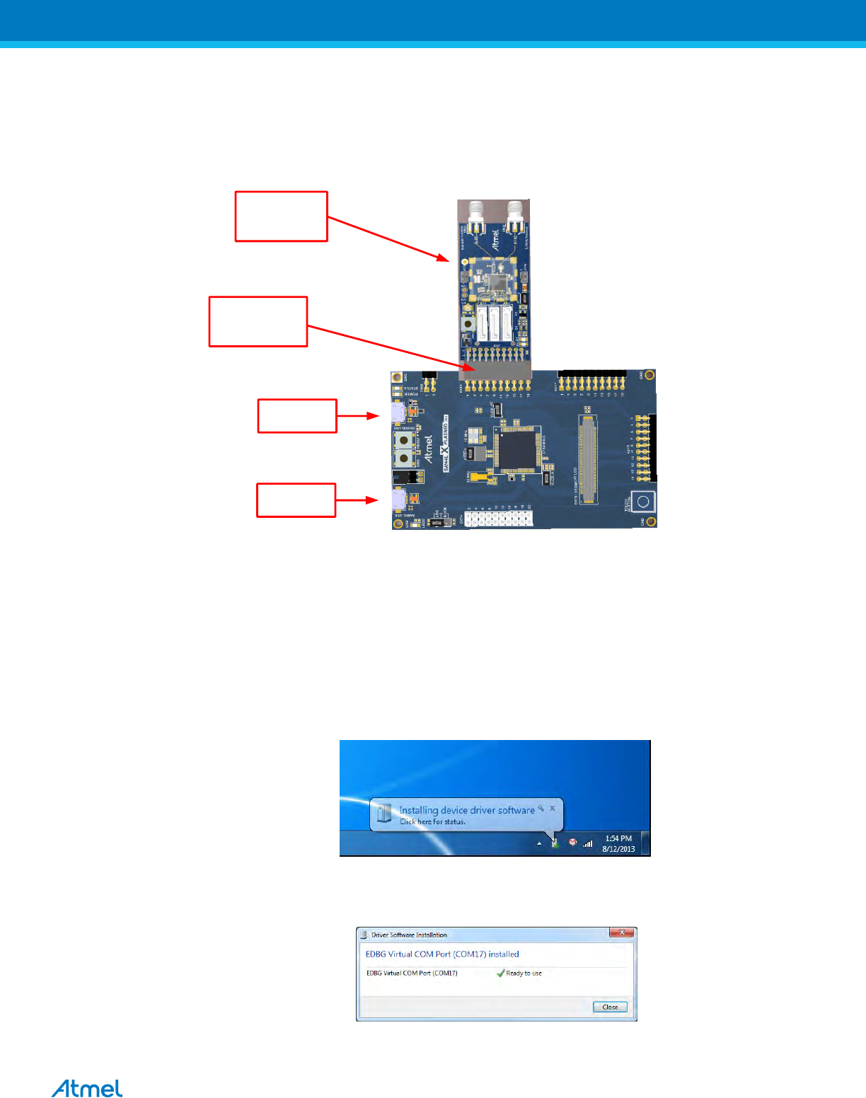
1. Connect one ATREB215-XPRO-A board to EXT1 connector of the SAM4L-Xplained Pro Board as shown
in the figure
USB for 900MHz
+ Programming
USB for 2400MHz
Connect REB215
Board at EXT1
REB215 Board
ATSAM4L Xplained PRO
COM, EDBG, 900MHz
DUT- REB215-XPRO
COM- 2.4GHz
RF 900MHz
RF 2.4GHz
Figure 7: Hardware Setup
2. Connect a micro USB cable from PC to the Debug USB port (USB for 900MHz) for 863MHz EU/915MHz
US ISM band operation
3. Connect a micro USB cable from PC to SAM4L USB (USB for 2400MHz) for 2.4GHz ISM band operation.
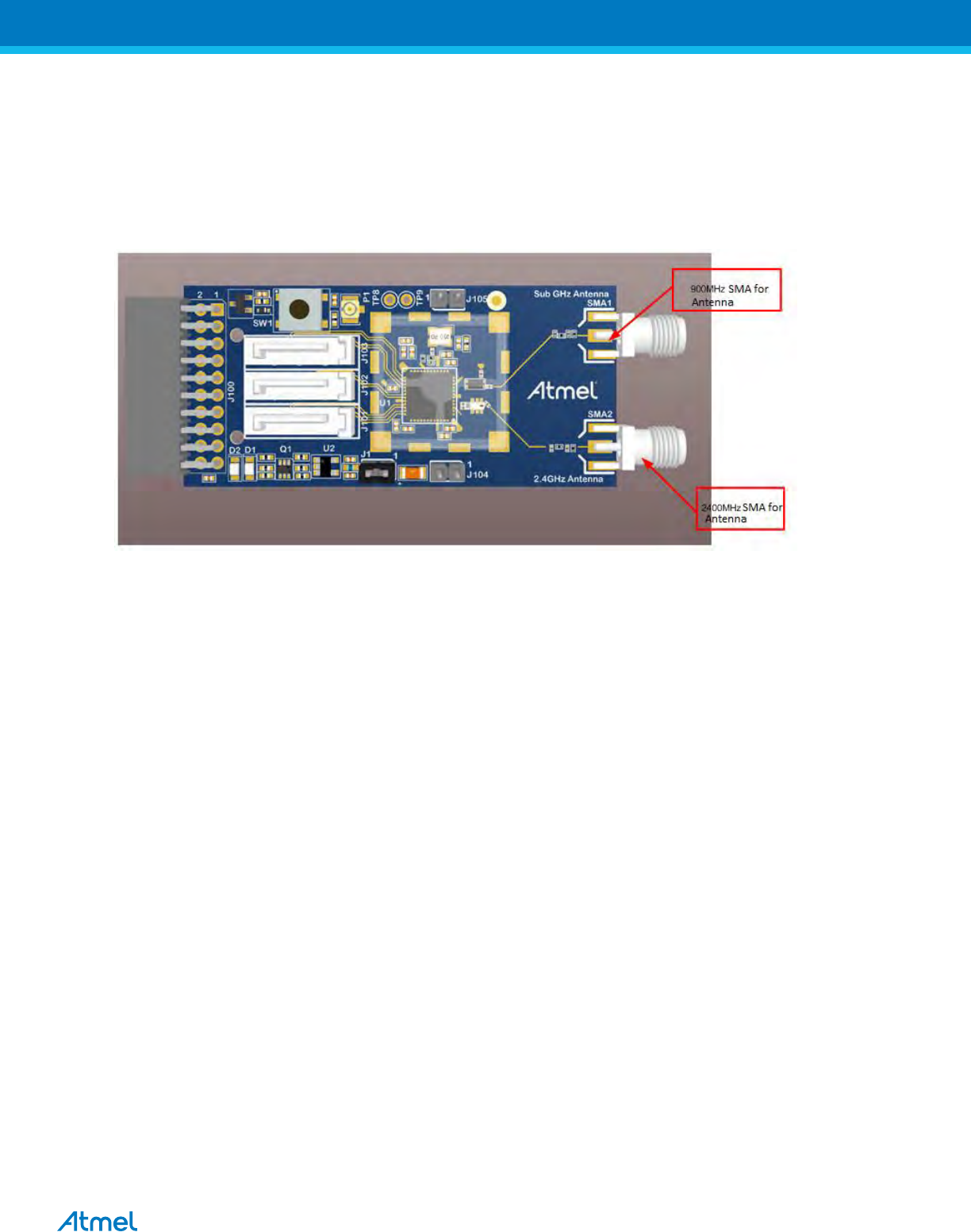
4. Connect 2.4GHz λ/4 Monopole Antenna (PSTG0-2400HS) with RF 2.4GHz port and connect Rubber
Stubby Antenna with SMA Male Straight (IJ28-SS) with RF 900MHz port
5. Next, EDBG Virtual COM port driver installation will begin automatically
Figure 8: EDBG Virtual COM PORT Driver installation
6. Click the taskbar notification. When the driver installation is successfully completed, there will be a
notificaion as shown below.
Figure 9: EDBG Virtual COM PORT Driver installation
Note: COM17 from the above figure is an example. The COM Port number varies depending upon the PC.
ATREB215-XPRO-A Test User Manual
6
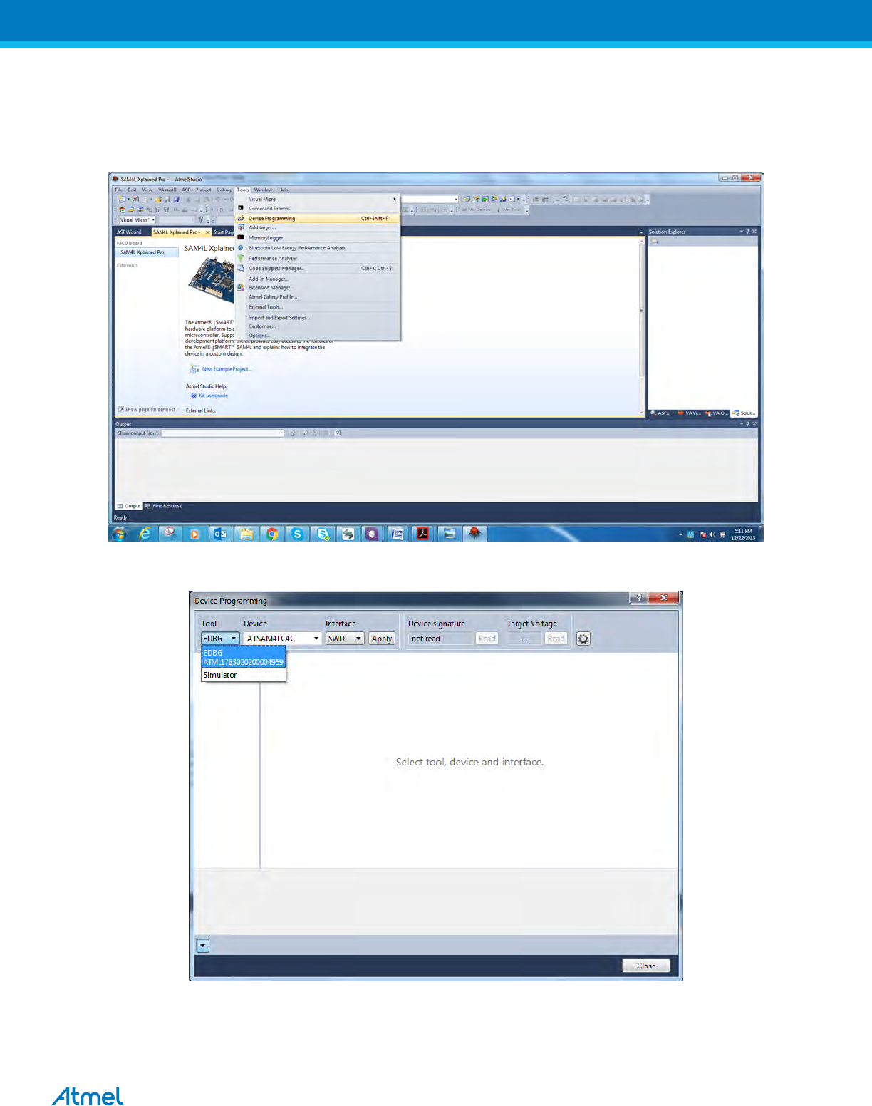
6. Programming SAM4L Xpro board to connect with ATREB215-Xpro-A
a. program the Test setup as follows: Open Atmel studio and Go to Tools menu and click Device
Programming
b. Select the tool as EDBG as shown below
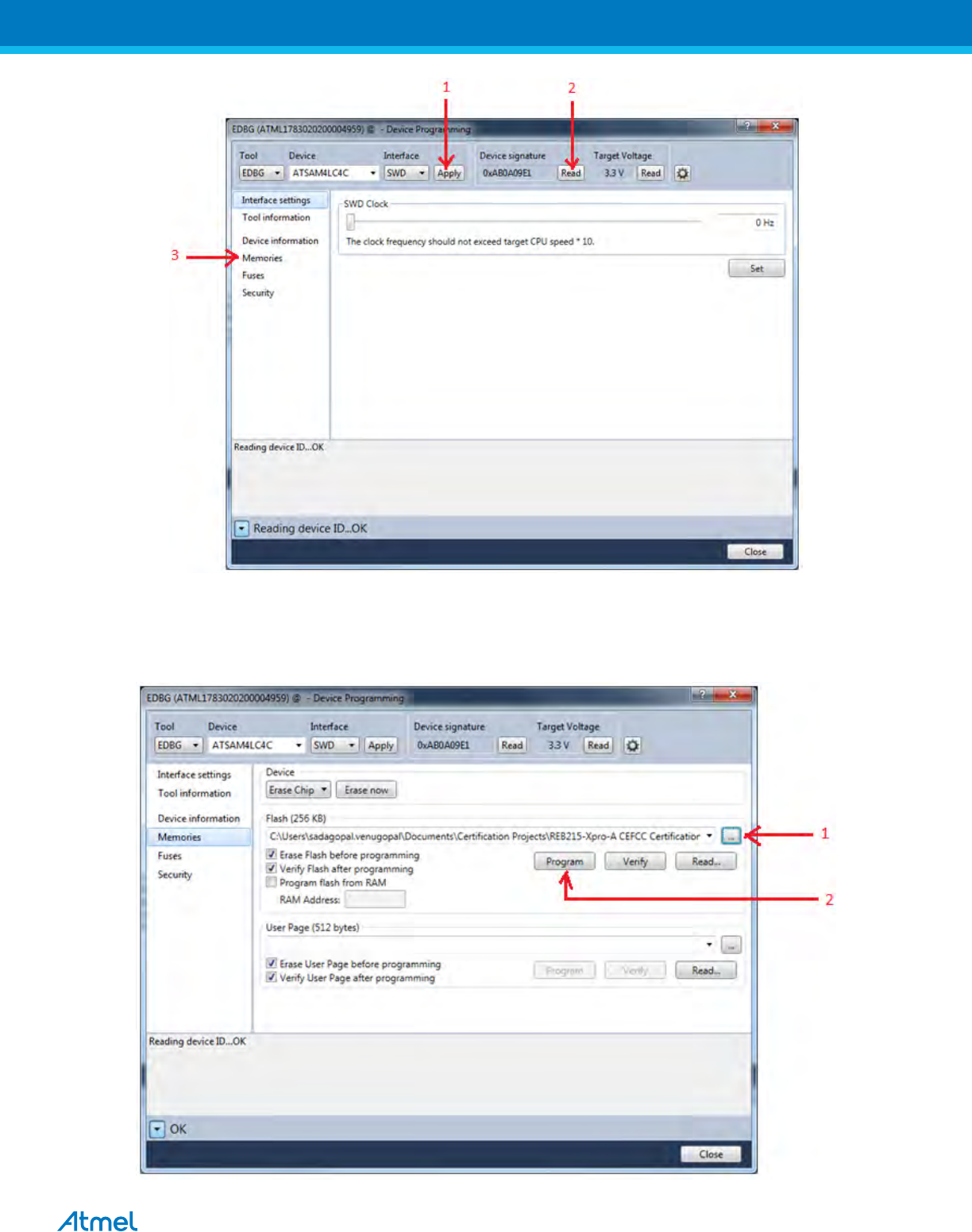
c. Click “Apply”, Status LED (yellow color) which is near to power LED starts to glow. Click “Read” which
reads Device signature and Target voltage. Next, Click memories for programming. Steps are shown
below in sequence
ATREB215-XPRO-A Test User Manual
7
d. Save the “PERFORMANCE_ANALYZER_2_SAM4L_RF215v3.hex” file into your PC and choose the
correct path of the saved hex file in Atmel Studio and click programming. Steps are shown below in
sequence. After programming, close the below window and start using Performance Analyzer.
ATREB215-XPRO-A Test User Manual
8
7. Performance Analyzer
1. Launch Atmel Studio tool by clicking the Atmel Studio icon
Figure 10: Launch Atmel Studio 6.1
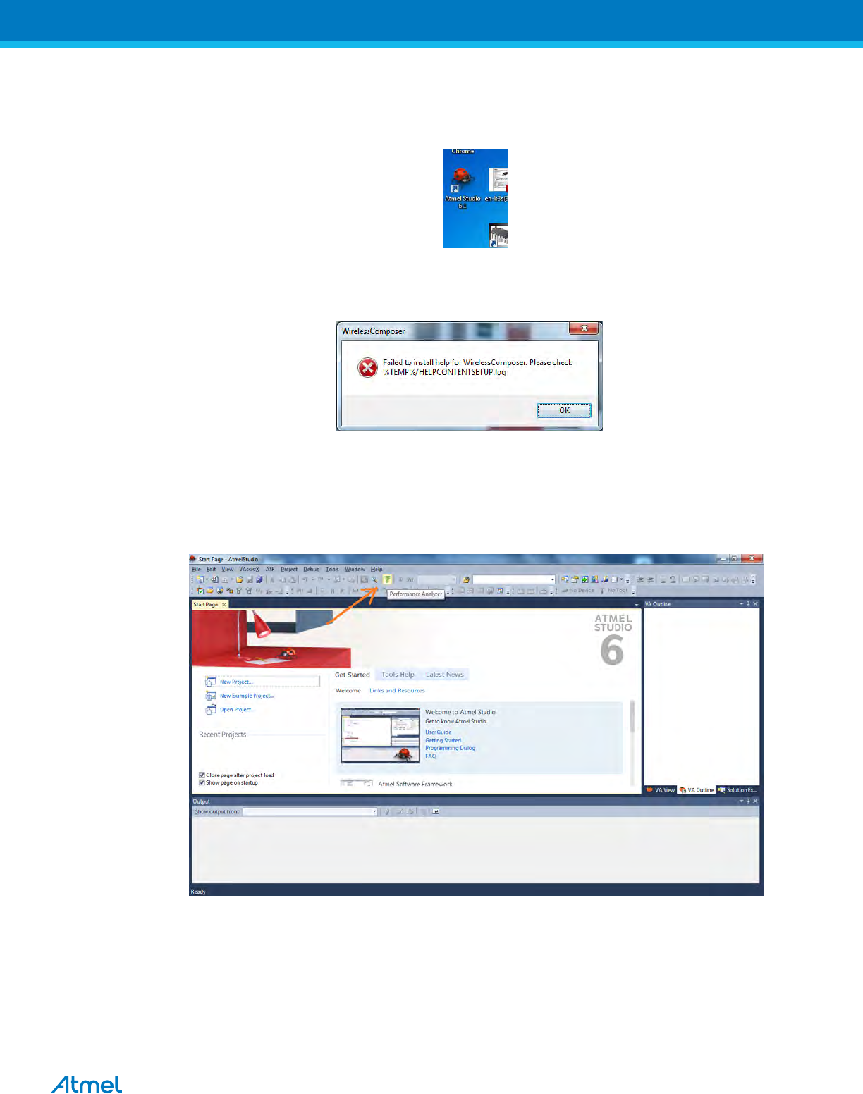
2. For the first time launch, Atmel studio will show the below error for Wireless Composer. Click Ok.
Figure 11: Wirless composer Error
3. From the Atmel Studio Start page, launch Performance Analyzer utility by clicking the icon as shown in below
figure.
Figure 12: Atmel Studio 6.1 – Start Page
4. After clicking the Performance Analyzer icon, Performance Analyzer window will open as shown in the following
figure.

ATREB215-XPRO-A Test User Manual
9
Figure 13: Performance Analyzer
Ensure the DuT is connected to the PC as explained in Section 5 and step 1
8. Tx Test (Single node / Continuous Transmission) for Sub-1GHz CE Testing
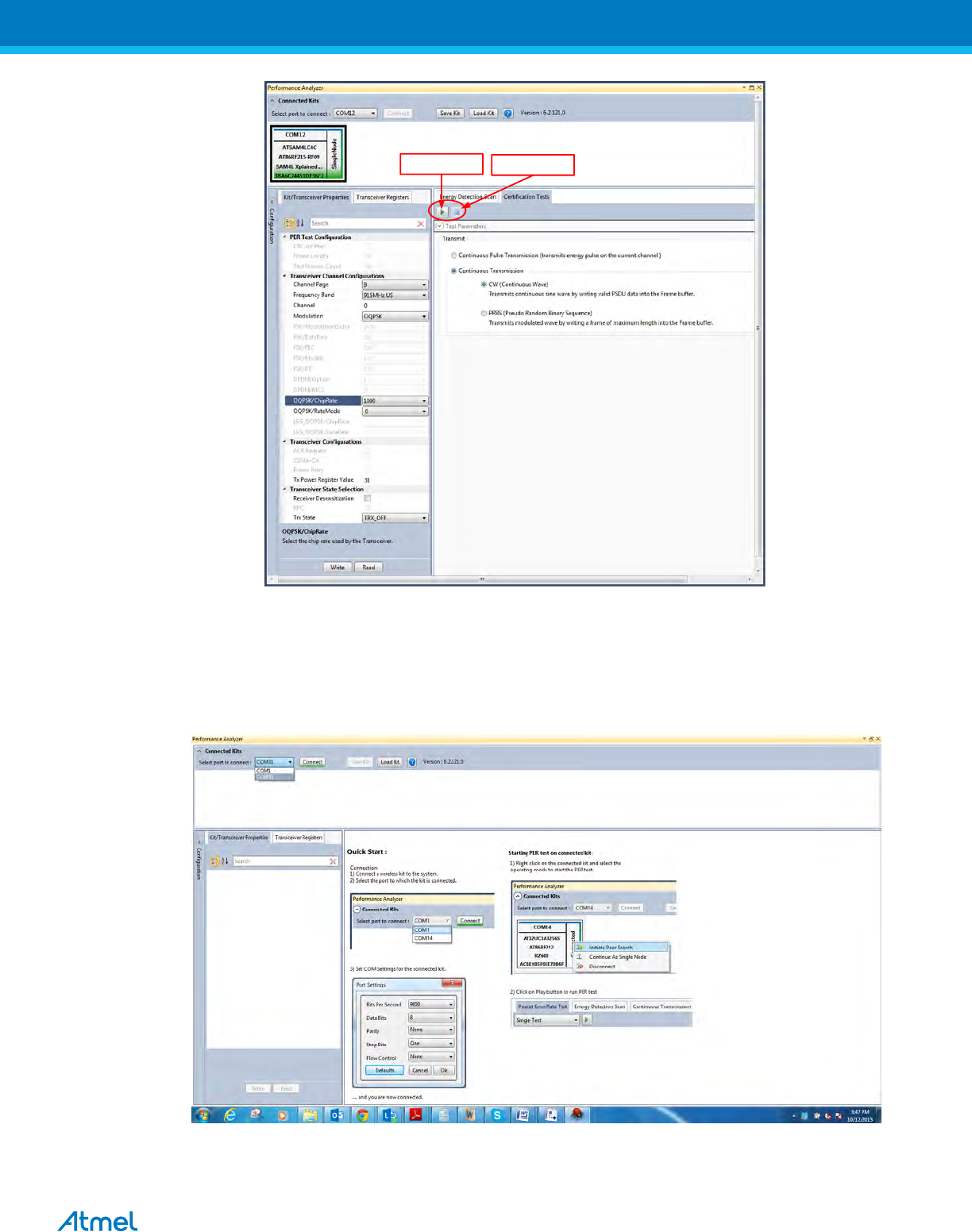
1. Select the COM Port from the dropdown menu and select a COM port to which the kit to be connected and
click “Connect”
Figure 14: Performance Analyzer – COM Port Selection
Note: COM17 from the above figure is an example. The COM Port number varies depending upon the PC.
2. Set the COM settings from the pop-up window. Click “Defaults” and then click “OK”
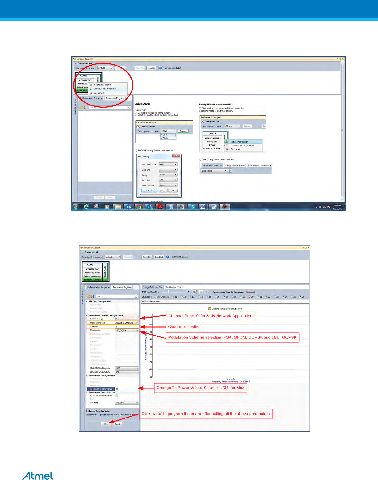
3. To check “transmit only” functionality; right click on the Kit information area select “Continue as a single node”.
This setting is used for continuous transmission.
ATREB215-XPRO-A Test User Manual
10
Figure 15: Performance Analyzer – Kit Information
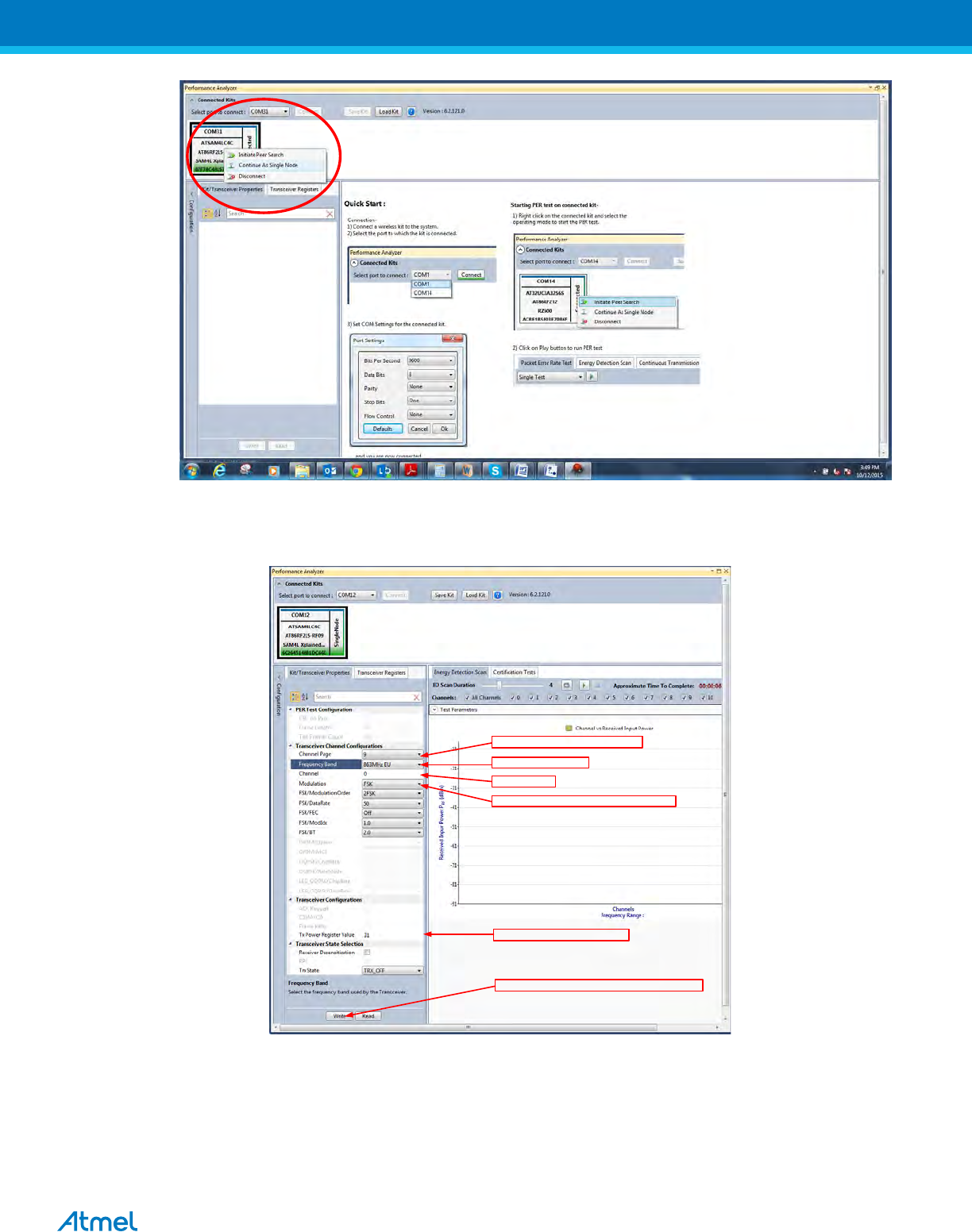
4. Kit / Transceiver properties, Channel Page, Frequency Band, Channel Number, Modulation Scheme and
Power level can also be changed in the Performance Analyzer window.
Channels Page ‘9’ for SUN Networ Application
863MHz EU or 915MHz US
Channel Selection
Modulation scheme selection: FSK, OFDM and OQPSK
Tx Power Value: ‘0’ for min & ‘31’ for Max
Click ‘write’ to program the board after setting all the parameters
Figure 16: Performance Analyzer – Transceiver configuration
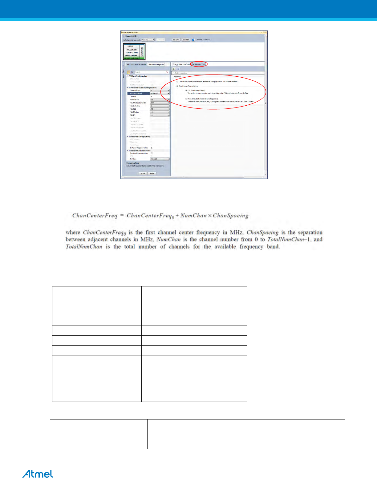
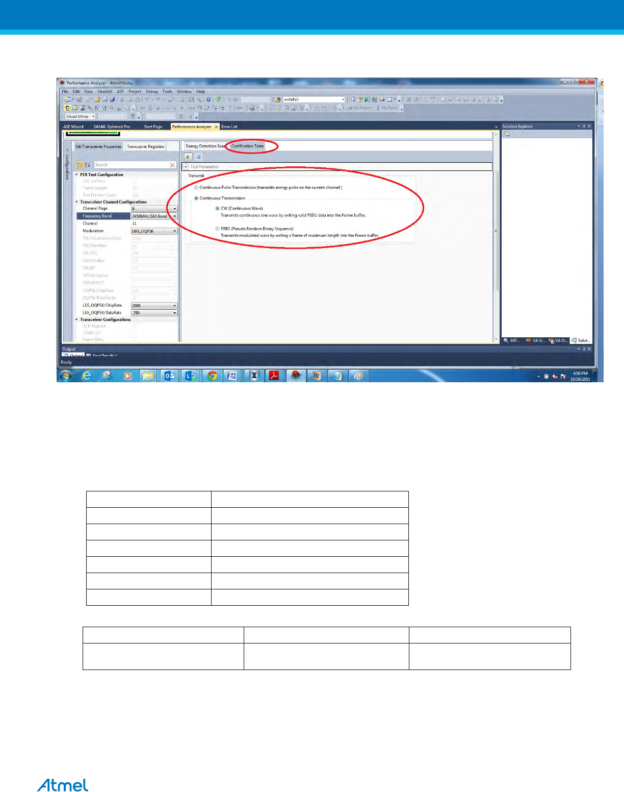
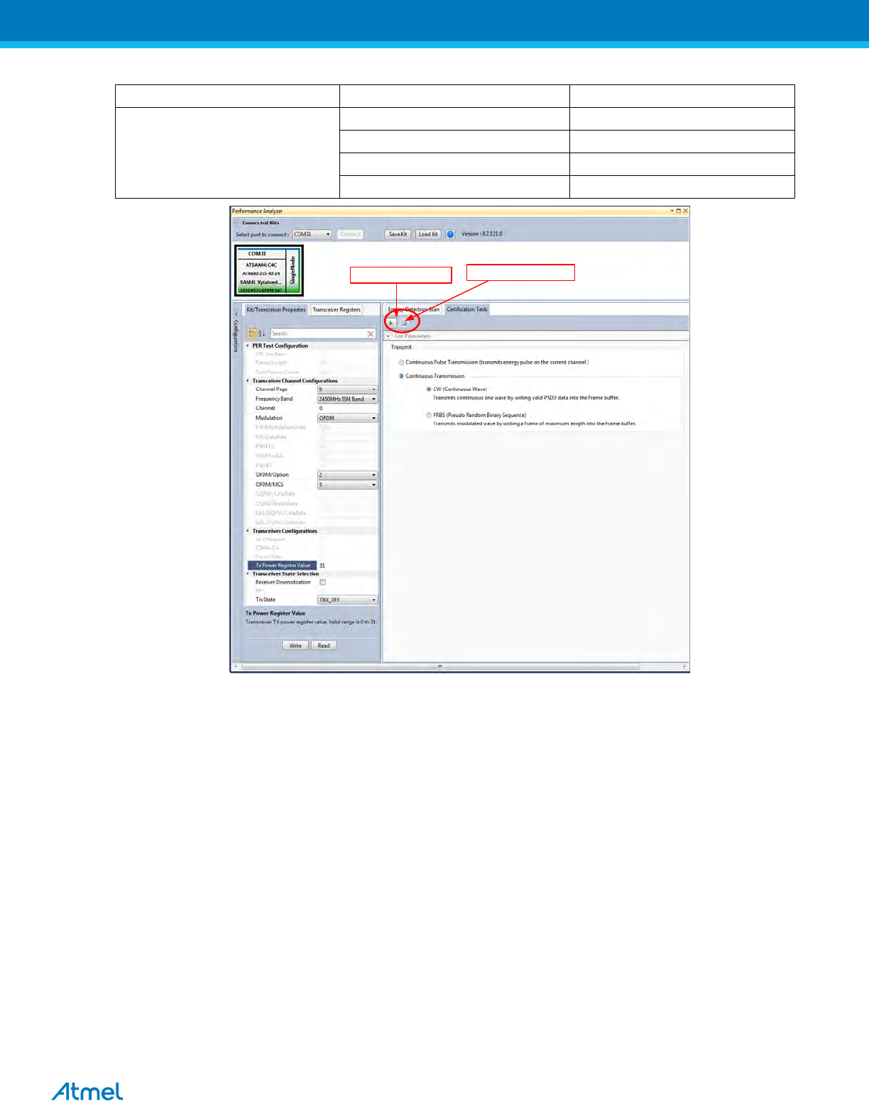
5. To Transmit CW mode or PRBS mode, click on Certification tab and Continuous transmission and CW or
PRBS
ATREB215-XPRO-A Test User Manual
11
Figure 17: Performance Analyzer – Continuous Tx mode configuration
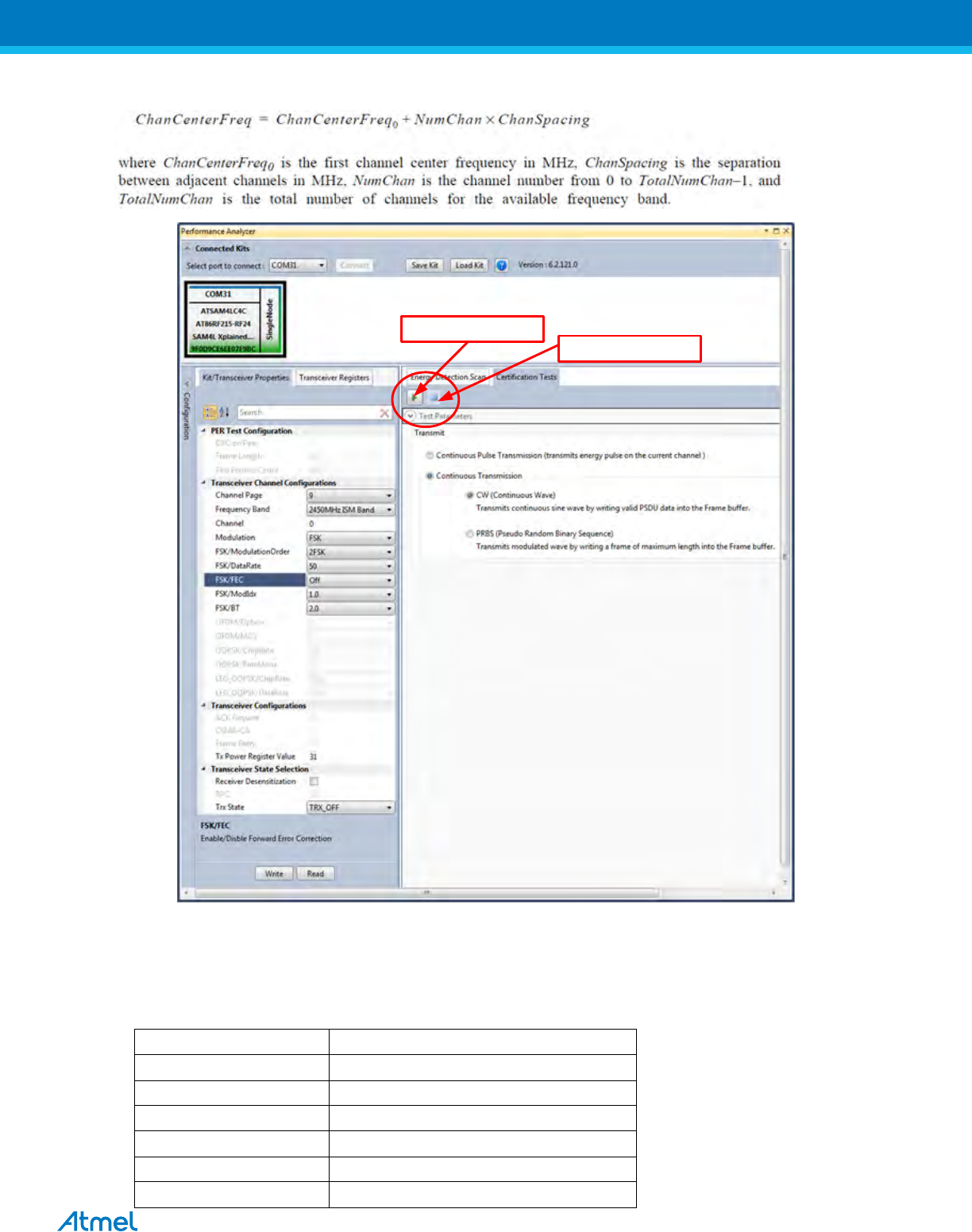
The center frequency of the MR-FSK, OFDM and OQPSK channels (except the OQPSK operating
in the 868–870 MHz) band is defined as follows:
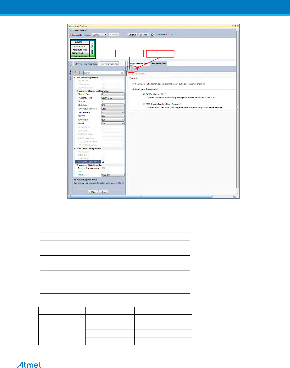
8.1 Tx Test: MR-FSK operating mode #1, 50kbit/s, 14dBm
Performance Analyzer configuration settings are
Table 1:- Board setting
Performance Analyzer Parameter
Setting for MR-FSK operating mode #1
Channel Page
9
Frequency band
863MHz EU (863MHz to 870MHz)
Channel
0 to 33
Modulation
FSK
FSK/ModulationOrder
2FSK
FSK/DataRate
50 kb/s
FSK/FEC
On
FSK/ModIdx
1.0
FSK/BT
Leave at default value; this is applicable only
for GFSK mode
Tx Power Register Value
‘31’ for Max Power (14dBm)
Table 2:
Frequency band (MHz)
Parameter
MR-FSK Operating mode #1
(863MHz to 870MHz)
Channel spacing (kHz)
200
ChanCenterFreq0 (MHz)
863.125
ATREB215-XPRO-A Test User Manual
12
Click here to start
Transmission
Click here to stop
Transmission
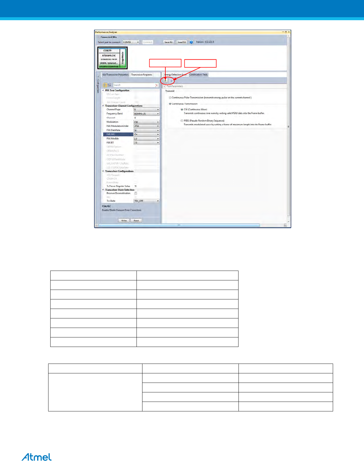
Figure 18: MR-FSK operating mode #1– Countinous transmit mode configuration
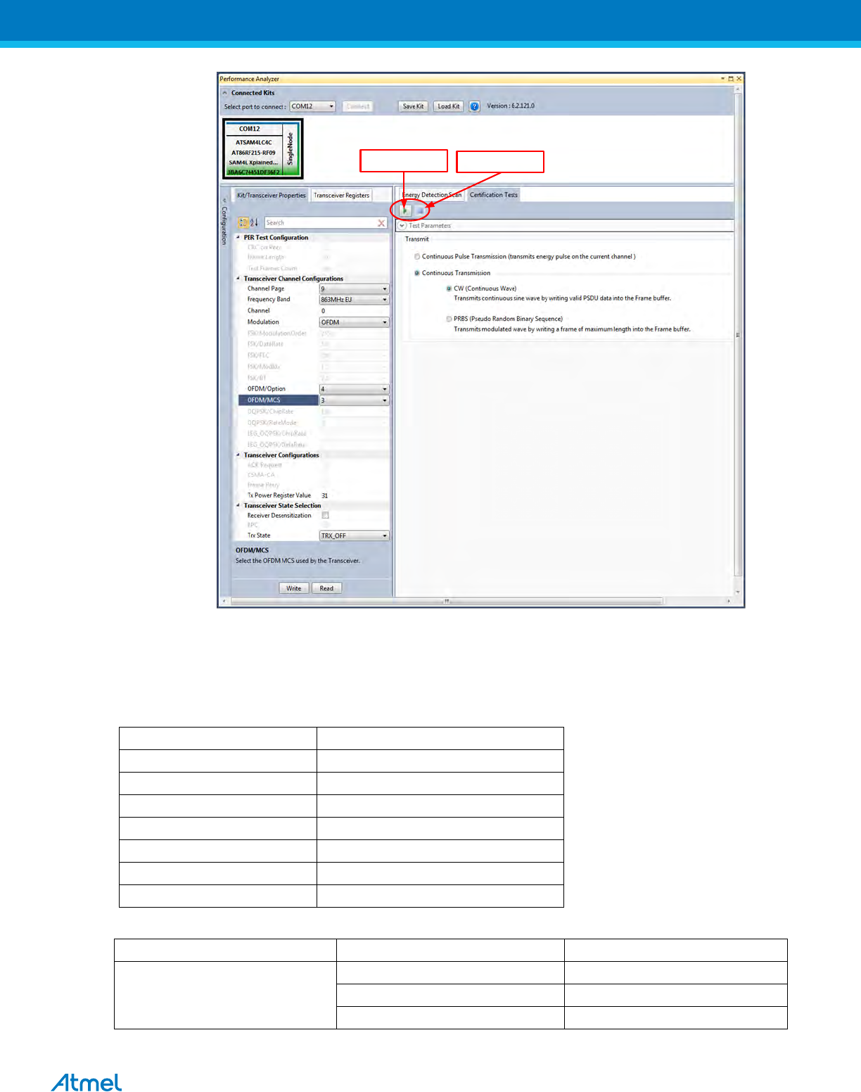
8.2 Tx Test: OFDM Option 4, MCS3, 14dBm
Performance Analyzer configuration settings are
Table 3:- Board setting
Performance Analyzer Parameter
Setting for OFDM Option 4, MCS3
Channel Page
9
Frequency band
863MHz EU (863MHz to 870MHz)
Channel
0 to 33
Modulation
OFDM
OFDM/Option
Option4
OFDM/MCS
MCS3
Tx Power Register Value
‘31’ for Max Power (14dBm)
Table 4:
Frequency band (MHz)
Parameter
OFDM Option 4, MCS 3 mode
(863MHz to 870MHz)
Nominal bandwidth (KHz)
156
Data rate
100 kb/s
Channel spacing (kHz)
200
ChanCenterFreq0 (MHz)
863.125
ATREB215-XPRO-A Test User Manual
13
Click here to start
Transmission
Click here to stop
Transmission
Figure 19: OFDM option 4, MCS3 – Countinous transmit mode configuration
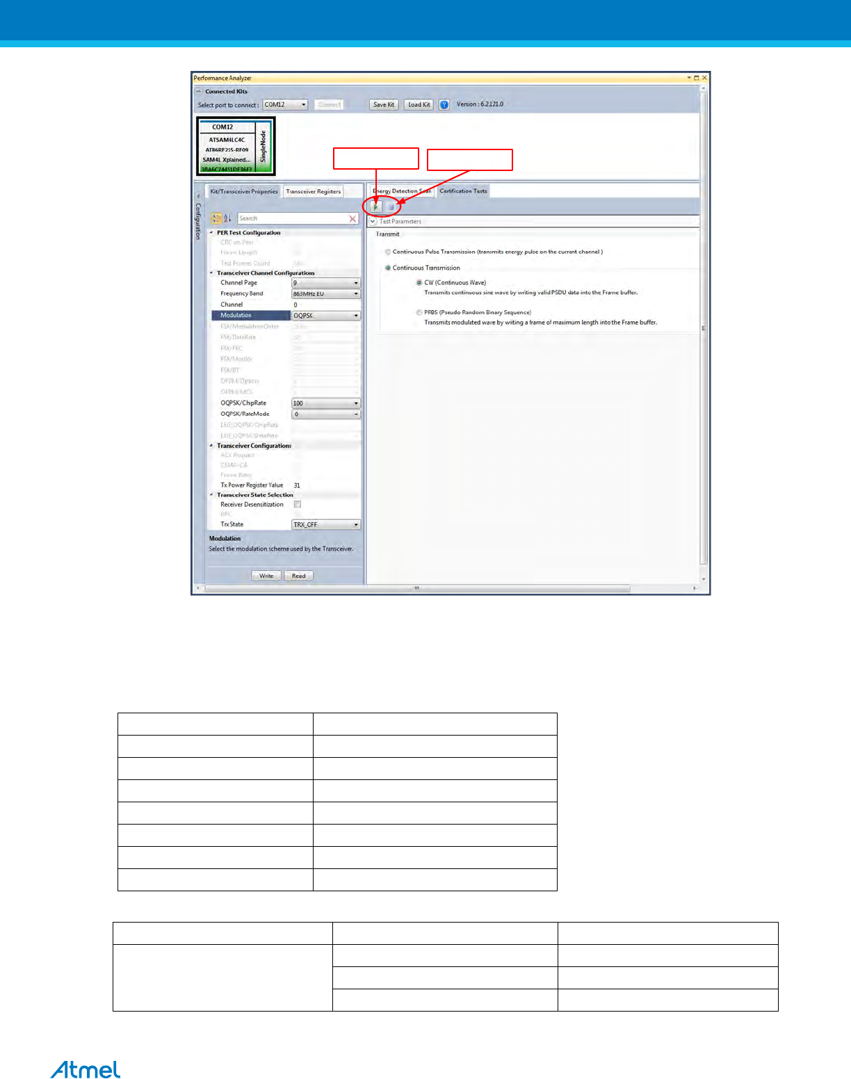
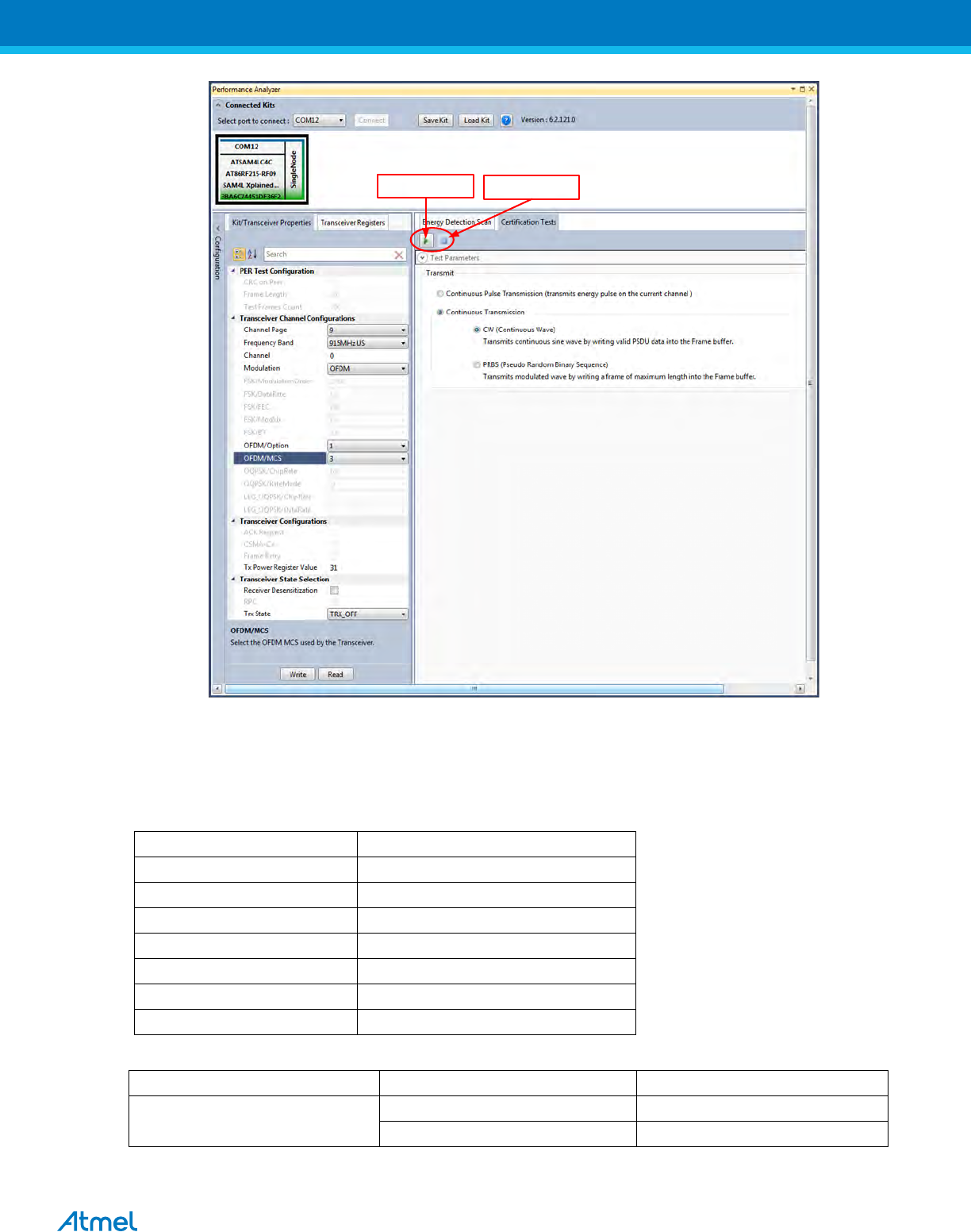
8.3 Tx Test: O-QPSK RateMode 0, 14dBm
Performance Analyser configuration settings are
Table 5
Performance Analyzer Parameter
Setting for O-QPSK RateMode 0
Channel Page
9
Frequency band
863MHz EU (868MHz to 870MHz)
Channel
0, 1 and 2
Modulation
OQPSK
OQPSK/ChipRate
ChipRate 100
OQPSK/RateMode
RateMode 0
Tx Power Register Value
‘31’ for Max Power
Table 6:
Frequency band
Channel Number
Channel Center Frequency (MHz)
(868MHz to 870MHz)
0
868.3
1
868.95
2
869.525
Data Rate: 6.25 kb/s
ATREB215-XPRO-A Test User Manual
14
Click here to start
Transmission
Click here to stop
Transmission
Figure 20: O-QPSK RateMode 0 – Countinous transmit mode configuration
8.4 Tx Test: O-QPSK RateMode 3, 14dBm
Performance Analyser configuration settings are
Table 7
Performance Analyzer Parameter
Setting for O-QPSK RateMode 3
Channel Page
9
Frequency band
863MHz EU (868MHz to 870MHz)
Channel
0, 1 and 2
Modulation
OQPSK
OQPSK/ChipRate
ChipRate 100
OQPSK/RateMode
RateMode 3
Tx Power Register Value
‘31’ for Max Power
Table 8:
Frequency band
Channel Number
Channel Center Frequency (MHz)
(868MHz to 870MHz)
0
863.3
1
868.95
2
869.525
Data Rate: 50 kb/s
ATREB215-XPRO-A Test User Manual
15
Figure 21: O-QPSK RateMode 3 – Countinous transmit mode configuration
9. Tx Test (Single node / Continuous Transmission) for Sub-1GHz FCC Testing
9.1 Tx Test: MR-FSK operating mode #1, 50kbit/s, 14dBm
Performance Analyzer configuration settings are
Table 9:- Board setting
Performance Analyzer Parameter
Setting for MR-FSK operating mode #1
Channel Page
9
Frequency band
915MHz US (902MHz to 928MHz)
Channel
1 to 127
Modulation
FSK
FSK/ModulationOrder
2FSK
FSK/DataRate
50 kb/s
FSK/FEC
on
FSK/ModIdx
1.0
FSK/BT
Leave at default value; this is applicable only
for GFSK mode
Tx Power Register Value
‘31’ for Max Power (14dBm)
Table 10:
Frequency band (MHz)
Parameter
MR-FSK Operating mode #1
915MHz ISM Band
Channel spacing (kHz)
200
ChanCenterFreq1 (MHz)
902.4
ATREB215-XPRO-A Test User Manual
16
Click here to start
Transmission
Click here to stop
Transmission
Figure 22: MR-FSK operating mode #1– Countinous transmit mode configuration
9.2 Tx Test: OFDM Option 1, MCS3, 14dBm
Performance Analyzer configuration settings are
Table 11:- Board setting
Performance Analyzer Parameter
Setting for OFDM Option 1, MCS3
Channel Page
9
Frequency band
915MHz US (902MHz to 928MHz)
Channel
0 to 19
Modulation
OFDM
OFDM/Option
Option1
OFDM/MCS
MCS3
Tx Power Register Value
‘31’ for Max Power (14dBm)
Table 12:
Frequency band (MHz)
Parameter
OFDM Option 1, MCS 3 mode
915MHz ISM Band
Nominal bandwidth (KHz)
1094
Data rate
800 kb/s
Channel spacing (kHz)
1200
ChanCenterFreq0 (MHz)
903.2
ATREB215-XPRO-A Test User Manual
17
Click here to start
Transmission
Click here to stop
Transmission
Figure 23: OFDM option1, MCS3 – Countinous transmit mode configuration
9.3 Tx Test: O-QPSK RateMode 0, 14dBm
Performance Analyser configuration settings are
Table 13
Performance Analyzer Parameter
Setting for O-QPSK RateMode 0
Channel Page
9
Frequency band
915MHz US (902MHz to 928MHz)
Channel
0 to 11
Modulation
OQPSK
OQPSK/ChipRate
ChipRate 1000
OQPSK/RateMode
RateMode 0
Tx Power Register Value
‘31’ for Max Power
Table 14:
Frequency band (MHz)
Parameter
O-QPSK RateMode 0
915MHz ISM Band
Channel spacing (MHz)
2
ChanCenterFreq0 (MHz)
904
Data Rate: 31.25 kb/s
ATREB215-XPRO-A Test User Manual
18
Click here to start
Transmission
Click here to stop
Transmission
Figure 24: O-QPSK RateMode 0 – Countinous transmit mode configuration
10. Tx Test for 2.4GHz Band (Single node / Continuous Transmission (CW/PRBS))
1. Select the COM Port from the dropdown menu and select a COM port to which the kit to be connected and
click “Connect”
Figure 14: Performance Analyzer – COM Port Selection
Note: COM17 from the above figure is an example. The COM Port number varies depending upon the PC.
ATREB215-XPRO-A Test User Manual
19
2. Set the COM settings from the pop-up window. Click “Defaults” and then click “OK”
3. To check “transmit only” functionality; right click on the Kit information area select “Continue as a single node”.
This setting is used for continuous transmission.
Figure 15: Performance Analyzer – Kit Information
4. Kit / Transceiver properties, Channel Page, Frequency Band, Channel Number, Modulation Scheme and
Power level can also be changed in the Performance Analyzer window.
Figure 16: Performance Analyzer – Transceiver configuration
ATREB215-XPRO-A Test User Manual
20
5. To Transmit CW mode or PRBS mode, click on Certification tab and Continuous transmission and CW or
PRBS
Figure 17: Performance Analyzer – Continuous Tx mode configuration
10.1 Tx Test - Legacy O-QPSK, 14dBm
Performance Analyzer configuration settings are
Table 15
Channel Page
9
Frequency band
2450MHz ISM Band
Channel
11 to 26 (2400MHz to 2483.5MHz)
Modulation
LEG_OQPSK
LEG_OQPSK/ChipRate
2000
LEG_OQPSK/DataRate
250
Tx Power Register Value
‘31’ for Max Power (14dBm)
Table 16:
Frequency band (MHz)
Parameter
Legacy O-QPSK mode
2400–2483.5 (Worldwide)
Channel spacing
5MHz
The center frequency of the Legacy O-QPSK channels is defined as follows:
Fc = 2405 + 5 (k – 11) in MHz, for k = 11, 12… 26
Where, k is the channel number.

ATREB215-XPRO-A Test User Manual
21
Click to start Transmission
Click to stop Transmission
Figure 18: Legacy O-QPSK - Countinous transmit mode configuration
10.2 Tx Test – MR-FSK operating mode #1, 50kbit/s, 14dBm
Performance Analyzer configuration settings are
Table 17:- Board setting
Channel Page
9
Frequency band
2450MHz ISM Band
Channel
3 to 409 (2400MHz to 2483.5MHz)
Modulation
FSK
FSK/ModulationOrder
2FSK
FSK/DataRate
50
FSK/FEC
off
FSK/ModIdx
1.0
FSK/BT
Leave at default value; this is applicable only for
GFSK mode
Tx Power Register Value
‘31’ for Max Power (14dBm)
Table 18:
Frequency band (MHz)
Parameter
MR-FSK Operating mode #1
2400–2483.5
(Worldwide)
Channel spacing (kHz)
200
ChanCenterFreq0 (MHz)
2400.2
ATREB215-XPRO-A Test User Manual
22
The center frequency of the MR-FSK and OFDM channels is defined as follows:
Click to start Transmission
Click to stop Transmission
Figure 19: MR-FSK operating mode #1– Countinous transmit mode configuration
10.3 Tx Test - OFDM Option 1, MCS3, 14dBm
Performance Analyzer configuration settings are
Table 19:- Board setting
Channel Page
9
Frequency band
2450MHz ISM Band
Channel
0 to 63 (2400MHz to 2483.5MHz)
Modulation
OFDM
OFDM/Option
Option1
OFDM/MCS
MCS3
Tx Power Register Value
‘31’ for Max Power (14dBm)
ATREB215-XPRO-A Test User Manual
23
Table 20:
Frequency band (MHz)
Parameter
OFDM Option 1, MCS 3 mode
2400–2483.5
(Worldwide)
Nominal bandwidth (KHz)
1094
Data rate
800Kbps
Channel spacing (kHz)
1200
ChanCenterFreq0 (MHz)
2401.2
Click to start Transmission
Click to stop Transmission
Figure 20: OFDM option1– Countinous transmit mode configuration
10.4 Tx Test - OFDM Option 2, MCS3, 14dBm
Performance Analyzer configuration settings are
Table 21:- Board setting
Channel Page
9
Frequency band
2450MHz ISM Band
Channel
0 to 96 (2400MHz to 2483.5MHz)
Modulation
OFDM
OFDM/Option
Option 2
OFDM/MCS
MCS 3
Tx Power Register Value
‘31’ for Max Power (14dBm)
ATREB215-XPRO-A Test User Manual
24
Table 22:
Frequency band (MHz)
Parameter
OFDM Option 2, MCS 3 mode
2400–2483.5
(Worldwide)
Nominal bandwidth (KHz)
552
Data rate
400Kbps
Channel spacing (kHz)
800
ChanCenterFreq0 (MHz)
2400.8
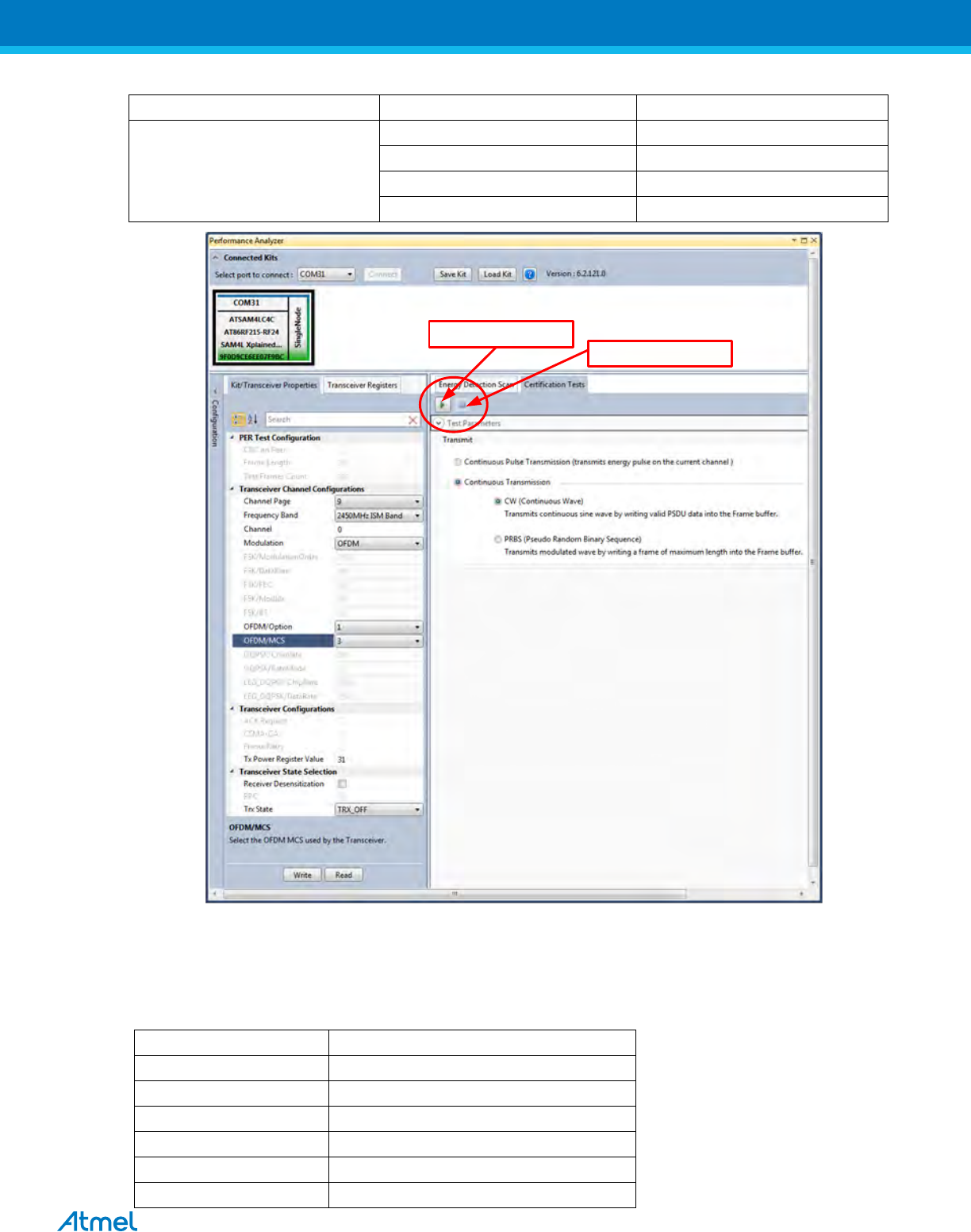
Click to start Transmission Click to stop Transmission
Figure 21: OFDM option2– Countinous transmit mode configuration
11. Tx-Rx Test (Transmit and Receive test) for Sub-1GHz CE Testing
1. Connect two DuTs with PC by USB cables to Debug USB for 863MHz EU/915 MHz US ISM band operations
and connect with SAM4L USB for 2.4GHz operation.
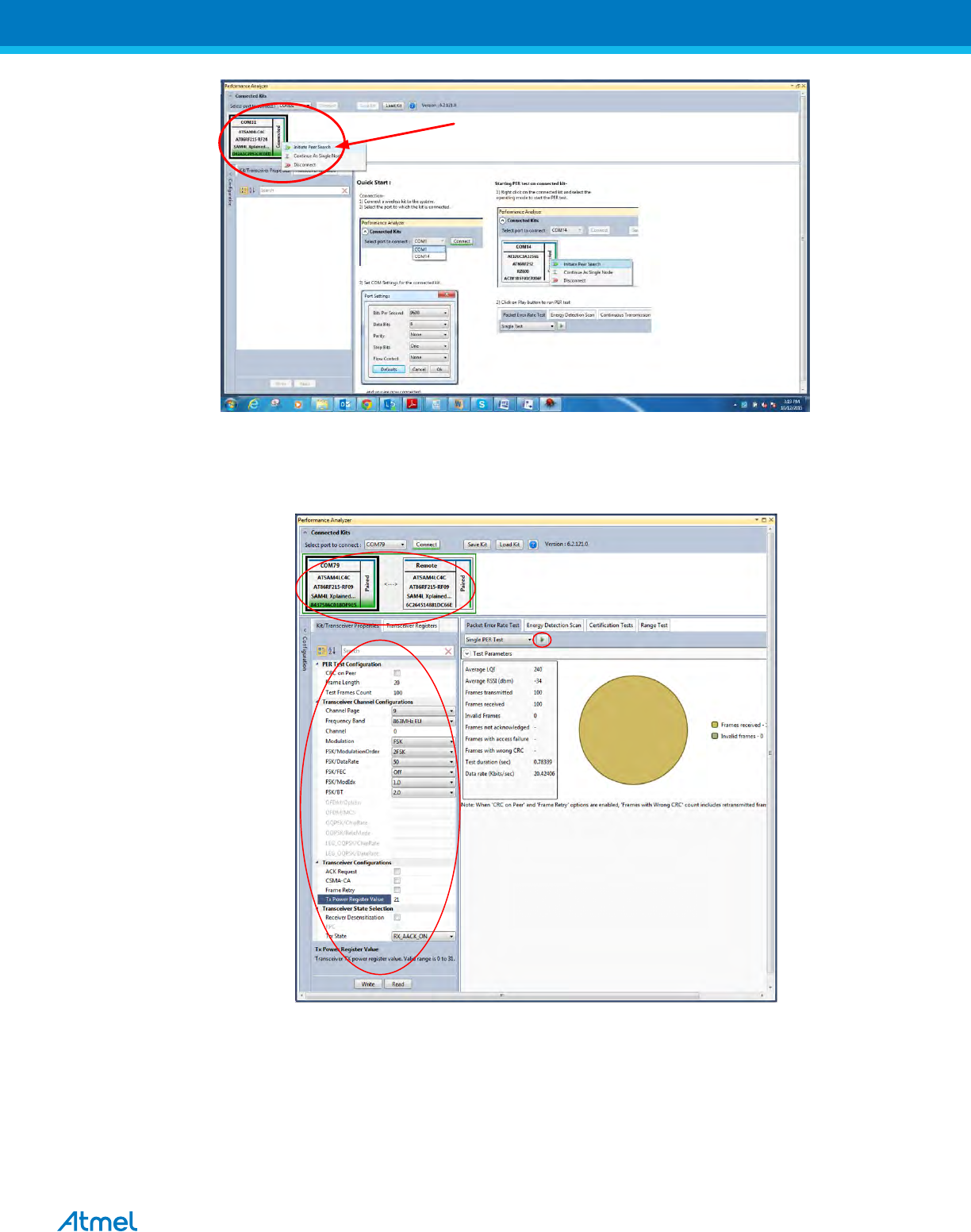
2. Select one COM Port and click ‘connect’ the device corresponding to that COM port is connected and select
“Initiate Peer Search” So other device connect by RF (RF Pairring). (Device connected to COM Port is
transmitter and other device is receiver)
ATREB215-XPRO-A Test User Manual
25
Figure 25: Performance Analyzer – Paring devices
3. When both the devices are paired, the following window appears and it is ready to perform PER (Packet Error
Rate) test. Tranmitting channel, number of frames (packets); Tx Power value can be configured from the left
side of the window.
Figure 26: Performance Analyzer – PER Test Configuration
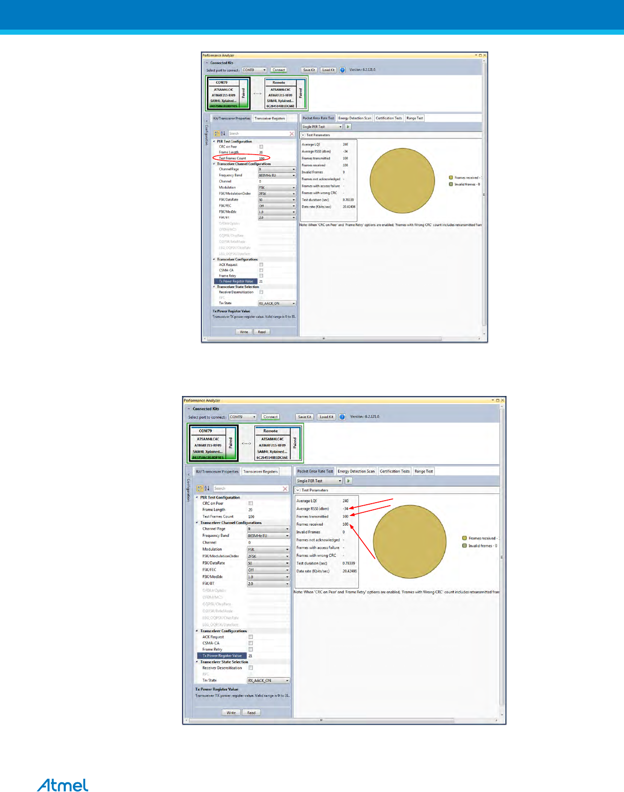
4. PER test is Transmit and Receive test. Number of transmit packets can be set by changing “Test Frames
Count”
ATREB215-XPRO-A Test User Manual
27
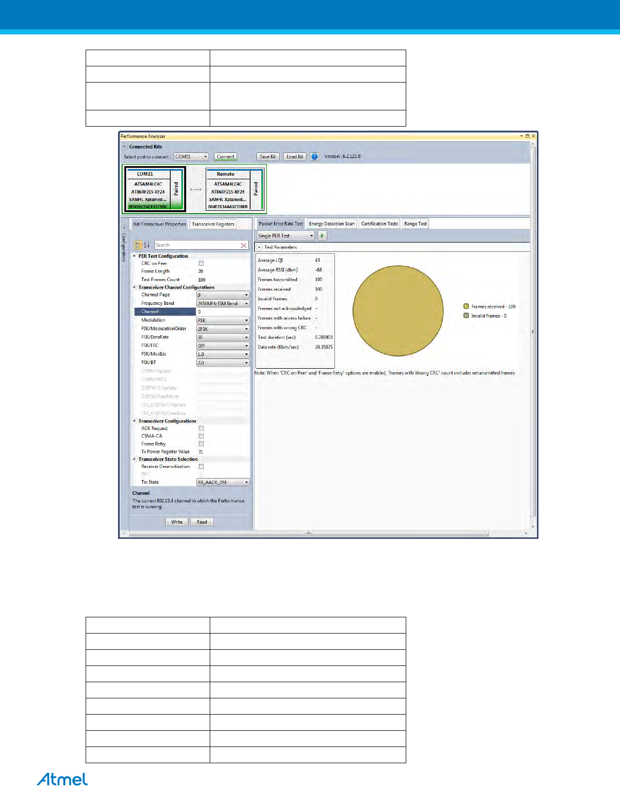
9.1 Tx-Rx Test: MR-FSK operating mode #1, 50kbit/s, 14dBm
Performance Analyzer configuration settings for transmit and receive test
Table 23:- Board setting
Performance Analyzer Parameter
Setting for MR-FSK operating mode #1
Frame length
20
Test Frames count
100
Channel Page
9
Frequency band
863MHz EU (863MHz to 870MHz)
Channel
0 to 33
Modulation
FSK
FSK/ModulationOrder
2FSK
FSK/DataRate
50 kb/s
FSK/FEC
on
FSK/ModIdx
1.0
FSK/BT
Leave at default value; this is applicable only
for GFSK mode
Tx Power Register Value
‘31’ for Max Power (14dBm)
Figure 29: MR-FSK operating mode #1- PER Test
ATREB215-XPRO-A Test User Manual
28
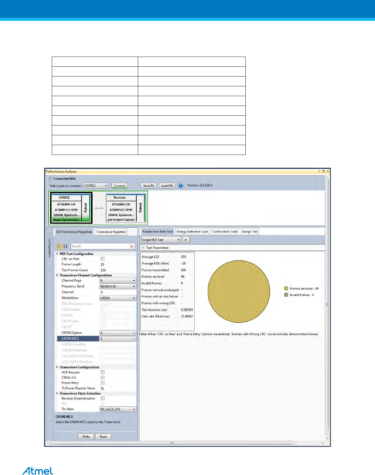
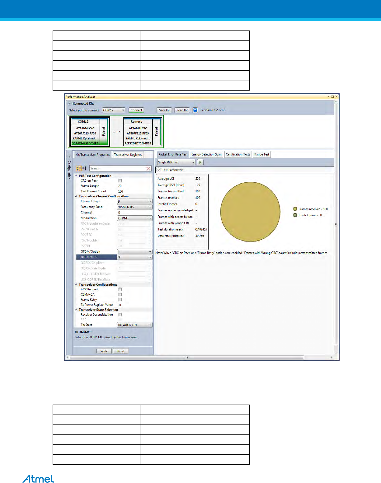
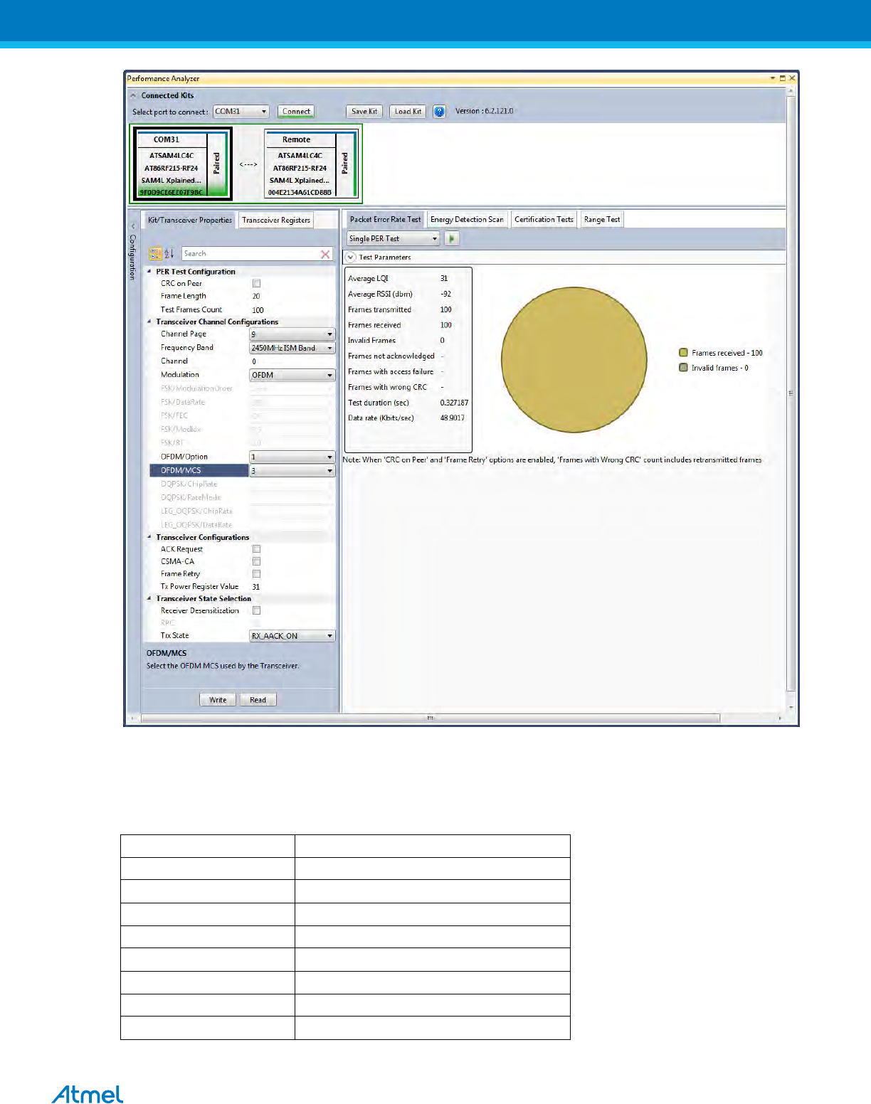
9.2 Tx-Rx Test: OFDM Option 4, MCS3, 14dBm
Performance Analyzer configuration settings for transmit and receive test
Table 24:- Board setting
Performance Analyzer Parameter
Setting for OFDM Option 4, MCS3 mode
Frame length
20
Test Frames count
100
Channel Page
9
Frequency band
863MHz EU (863MHz to 870MHz)
Channel
0 to 33
Modulation
OFDM
OFDM/Option
Option4
OFDM/MCS
MCS3
Tx Power Register Value
‘31’ for Max Power (14dBm)
Figure 30: OFDM Option4, MCS3 mode - PER Test
ATREB215-XPRO-A Test User Manual
29
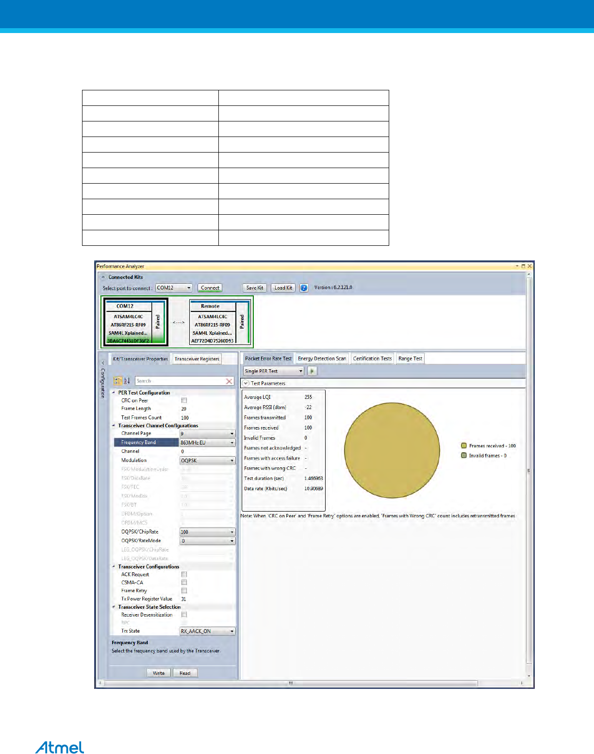
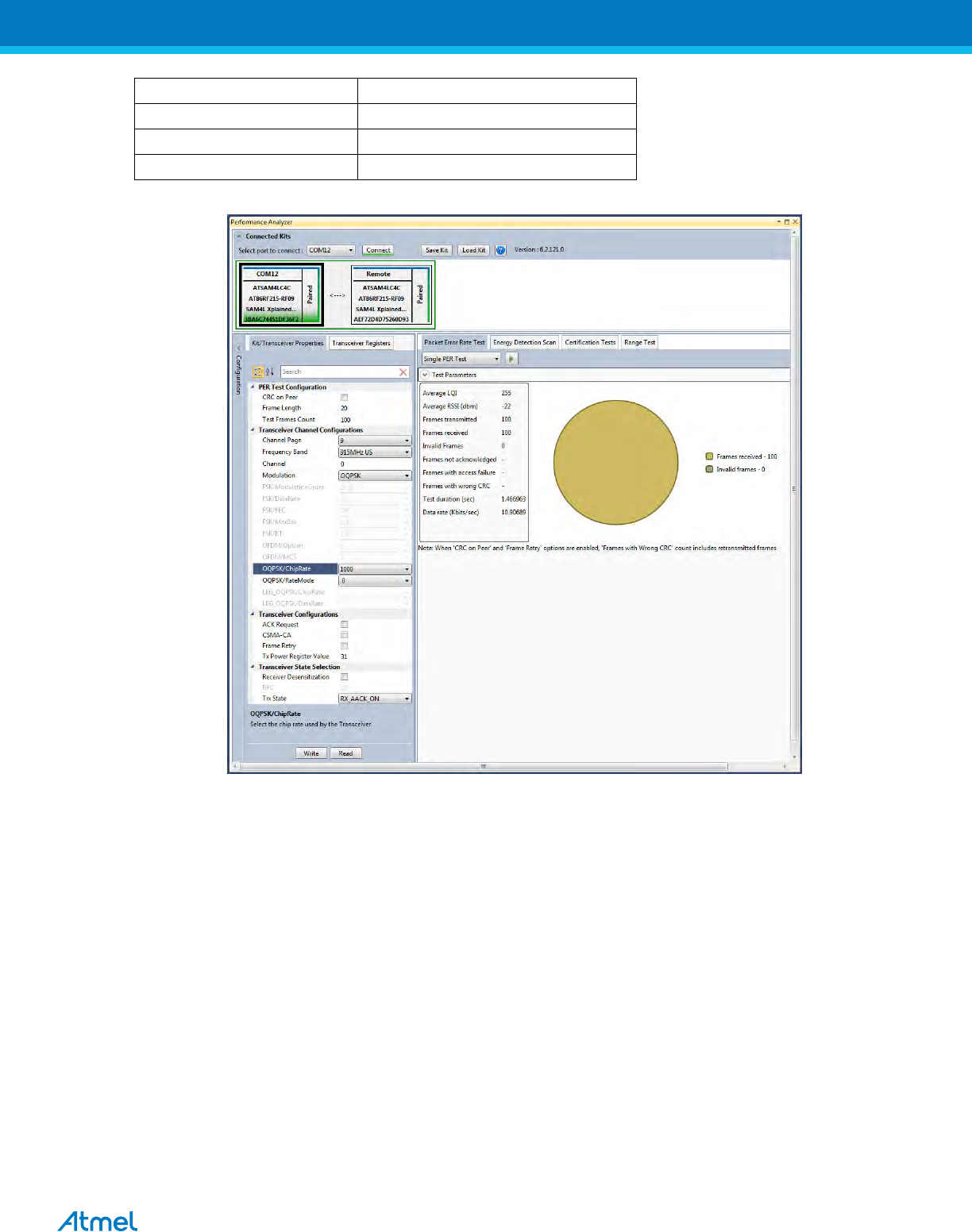
9.3 Tx-Rx Test: OQPSK, RateMode 0, 14dBm
Performance Analyser configuration settings for transmit and receive test
Table 25:- Board setting
Performance Analyzer Parameter
Setting for OQPSK, RateMode 0
Frame Length
20
Test Frames count
100
Channel Page
9
Frequency band
863MHz EU (868MHz to 870MHz)
Channel
0, 1 and 2
Modulation
OQPSK
OQPSK/ChipRate
ChipRate 100
OQPSK/RateMode
RateMode 0
Tx Power Register Value
31
Figure 31: OQPSK, RateMode 0 - PER Test
ATREB215-XPRO-A Test User Manual
30
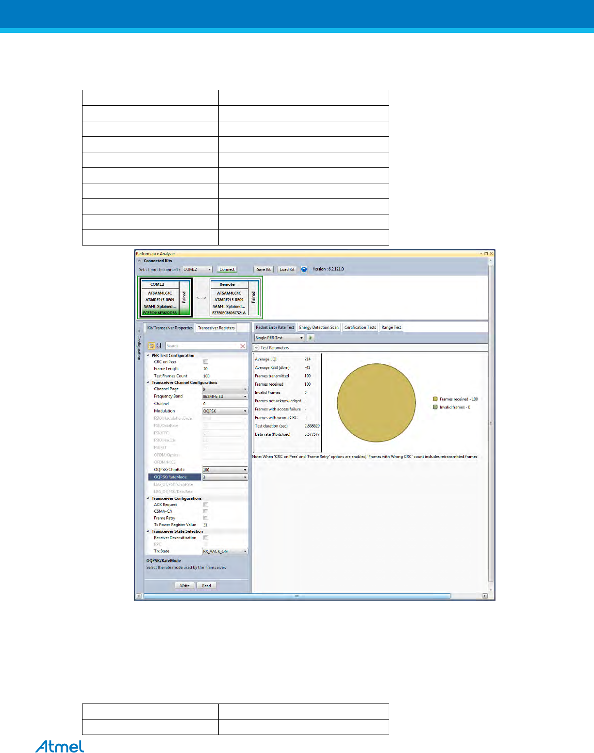
9.4 Tx-Rx Test: OQPSK, RateMode 3, 14dBm
Performance Analyser configuration settings for transmit and receive test
Table 26:- Board setting
Performance Analyzer Parameter
Setting for OQPSK, RateMode 3
Frame Length
20
Test Frames count
100
Channel Page
9
Frequency band
863MHz EU (868MHz to 870MHz)
Channel
0, 1 and 2
Modulation
OQPSK
OQPSK/ChipRate
ChipRate 100
OQPSK/RateMode
RateMode 3
Tx Power Register Value
31
Figure 32: OQPSK, RateMode 3 - PER Test
12. Tx-Rx Test (Transmit and Receive test) for Sub-1GHz FCC Testing
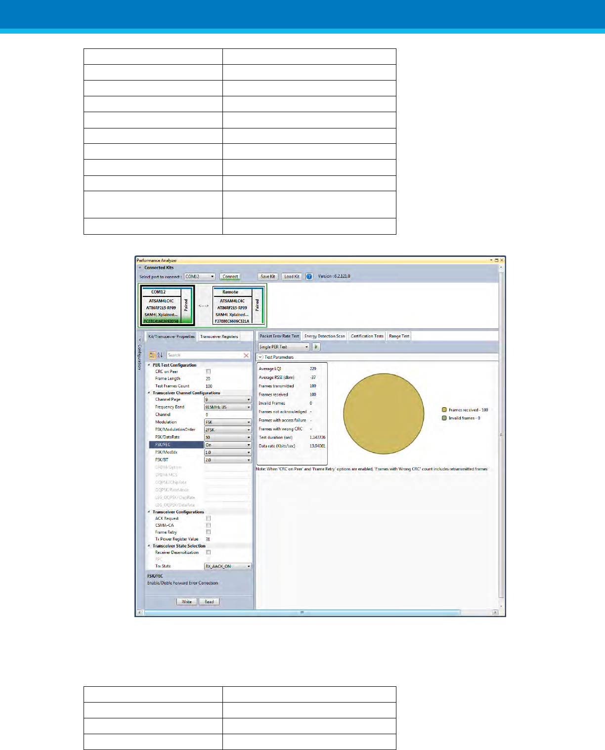
12.1 Tx-Rx Test: MR-FSK operating mode #1, 50kbit/s, 14dBm
Performance Analyzer configuration settings for transmit and receive test
Table 27:- Board setting
Performance Analyzer Parameter
Setting for MR-FSK operating mode #1
Frame length
20
ATREB215-XPRO-A Test User Manual
31
Test Frames count
100
Channel Page
9
Frequency band
915MHz US (902MHz to 928MHz)
Channel
1 to 127
Modulation
FSK
FSK/DataRate
50 kb/s
FSK/ModulationOrder
2FSK
FSK/FEC
on
FSK/ModIdx
1.0
FSK/BT
Leave at default value; this is applicable only
for GFSK mode
Tx Power Register Value
‘31’ for Max Power (14dBm)
Figure 33: MR-FSK operating mode #1- PER Test
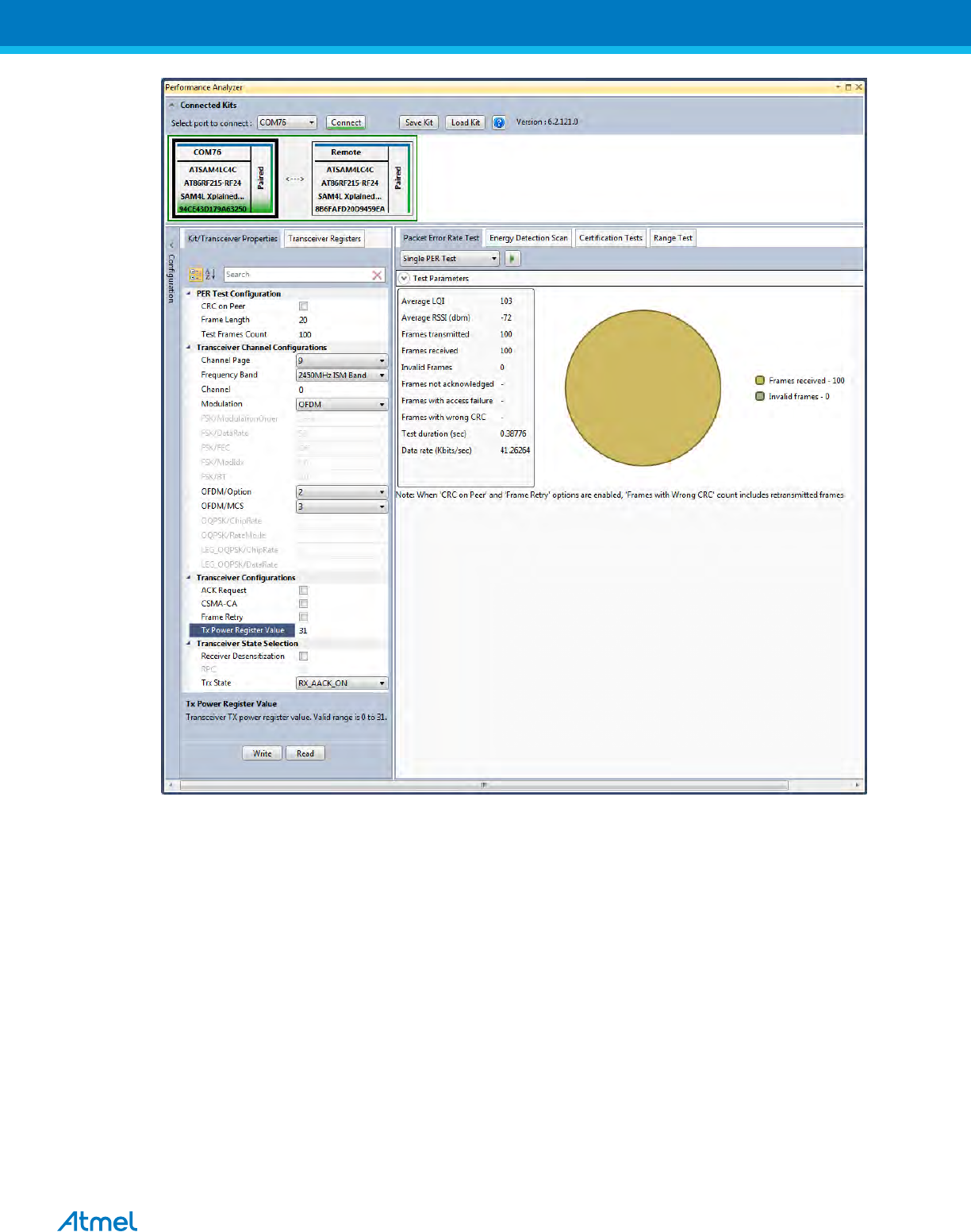
12.2 Tx-Rx Test: OFDM Option 1, MCS3, 14dBm
Performance Analyzer configuration settings for transmit and receive test
Table 28:- Board setting
Performance Analyzer Parameter
Setting for OFDM Option 1, MCS3 mode
Frame length
20
Test Frames count
100
Channel Page
9
ATREB215-XPRO-A Test User Manual
32
Frequency band
915MHz US (902MHz to 928MHz)
Channel
0 to 19
Modulation
OFDM
OFDM/Option
Option1
OFDM/MCS
MCS3
Tx Power Register Value
‘31’ for Max Power (14dBm)
Figure 34: OFDM Option 1, MCS3 mode - PER Test
12.3 Tx-Rx Test: OQPSK, RateMode 0, 14dBm
Performance Analyser configuration settings for transmit and receive test
Table 29:- Board setting
Performance Analyzer Parameter
Setting for O-QPSK RateMode 0
Frame Length
20
Test Frames count
100
Channel Page
9
Frequency band
915MHz US (902MHz to928MHz)
Channel
0 to 11
ATREB215-XPRO-A Test User Manual
33
Modulation
OQPSK
OQPSK/ChipRate
ChipRate 1000
OQPSK/RateMode
RateMode 0
Tx Power Register Value
31
Figure 35: OQPSK, RateMode 0 - PER Test
13. Tx-Rx Test for 2.4GHz Band (Transmit and Receive test)
1. Connect two devices with PC by USB cables and so both are power up.
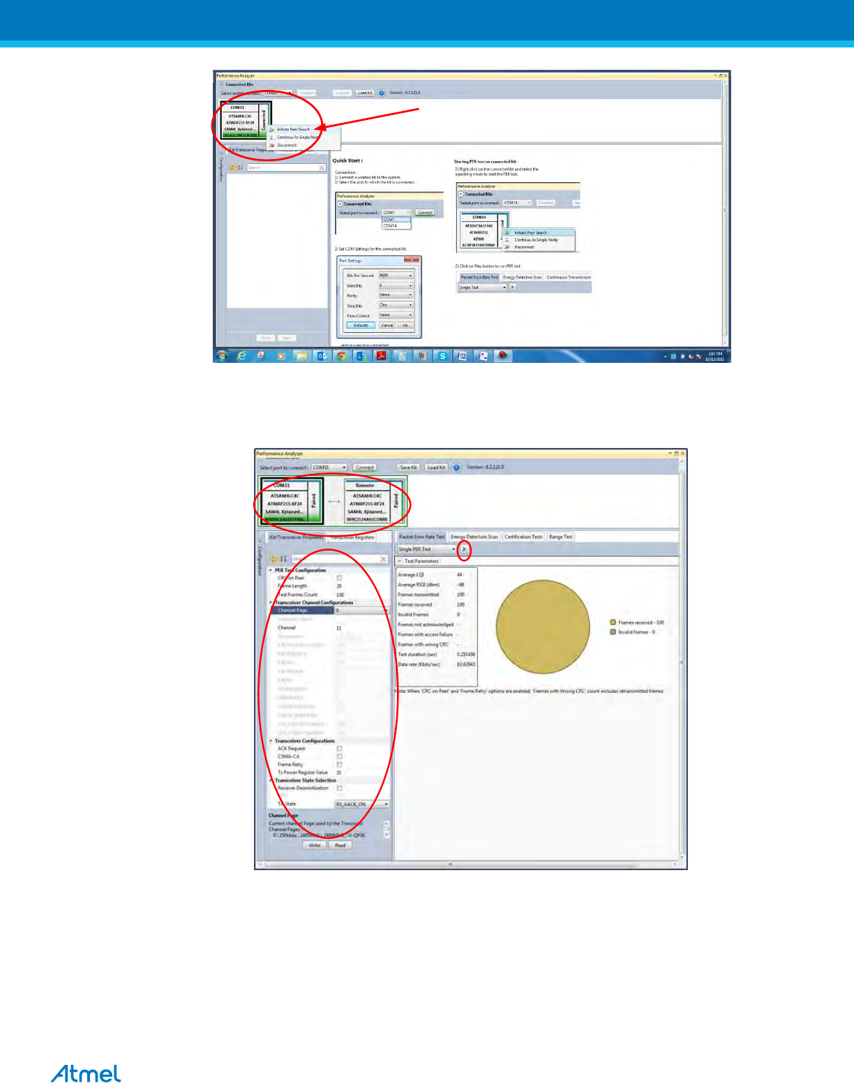
2. Select one COM Port and click ‘connect’ the device corresponding to that COM port is connected and select
“Initiate Peer Search” So other device connect by RF (RF Pairring). (Device connected to COM Port is
transmitter and other device is receiver)
ATREB215-XPRO-A Test User Manual
34
Figure 22: Performance Analyzer – Paring devices
3. When both the devices are paired, the following window appears and it is ready to perform PER (Packet Error
Rate) test. Tranmitting channel, number of frames (packets), Tx Power value can be configured from the left
side of the window.
Figure 23: Performance Analyzer – PER Test Configuration
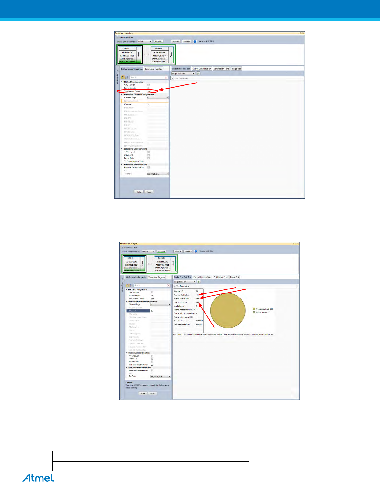
4. PER test is Transmit and Receive test. Number of transmit packets can be set by changing “Test Frames
Count”
ATREB215-XPRO-A Test User Manual
35
Figure 24: Performance Analyzer – Transmit Packets
5. Run Single PER Test. Test parameter window display the Transmit packets (Frames transmitted), Receive
packets (Frames received) and RSSI (receive signal strength)
Figure 25: Performance Analyzer – PER Test
9.5 Rx Test – Legacy O-QPSK, 14dBm
Performance Analyzer configuration settings for transmit and receive test
Table 30:- Board setting
Frame Length
20
Test Frames count
100

ATREB215-XPRO-A Test User Manual
36
Channel Page
9
Frequency band
2450MHz ISM Band
Channel
11 to 26 (2400MHz to 2483.5MHz)
Modulation
LEG_OQPSK
LEG_OQPSK/ChipRate
ChipRate 2000
LEG_OQPSK/DataRate
DataRate 250
Tx Power Register Value
‘31’ for Max Power (14dBm)
Figure 26: Legacy O-QPSK PER Test
9.6 Rx Test: MR-FSK operating mode #1, 50kbit/s, 14dBm
Performance Analyzer configuration settings for transmit and receive test
Table 31:- Board setting
Frame length
20
Test Frames count
100
Channel Page
9
Frequency band
2450MHz ISM Band
Channel
3 to 409 (2400MHz to 2483.5MHz)
Modulation
FSK
FSK/DataRate
50Kbps
FSK/ModulationOrder
2FSK
ATREB215-XPRO-A Test User Manual
37
FSK/FEC
off
FSK/ModIdx
1.0
FSK/BT
Leave at default value; this is applicable only for
GFSK mode
Tx Power Register Value
‘31’ for Max Power (14dBm)
Figure 27: MR-FSK operating mode #1- PER Test
9.7 Rx Test - OFDM Option 1, MCS3, 14dBm
Performance Analyzer configuration settings for transmit and receive test
Table 32:- Board setting
Frame length
20
Test Frames count
100
Channel Page
9
Frequency band
2450MHz ISM Band
Channel
0 to 63 (2400MHz to 2483.5MHz)
Modulation
OFDM
OFDM/Option
Option1
OFDM/MCS
MCS3
Tx Power Register Value
‘31’ for Max Power (14dBm)
ATREB215-XPRO-A Test User Manual
38
Figure 28: OFDM Option1- PER Test
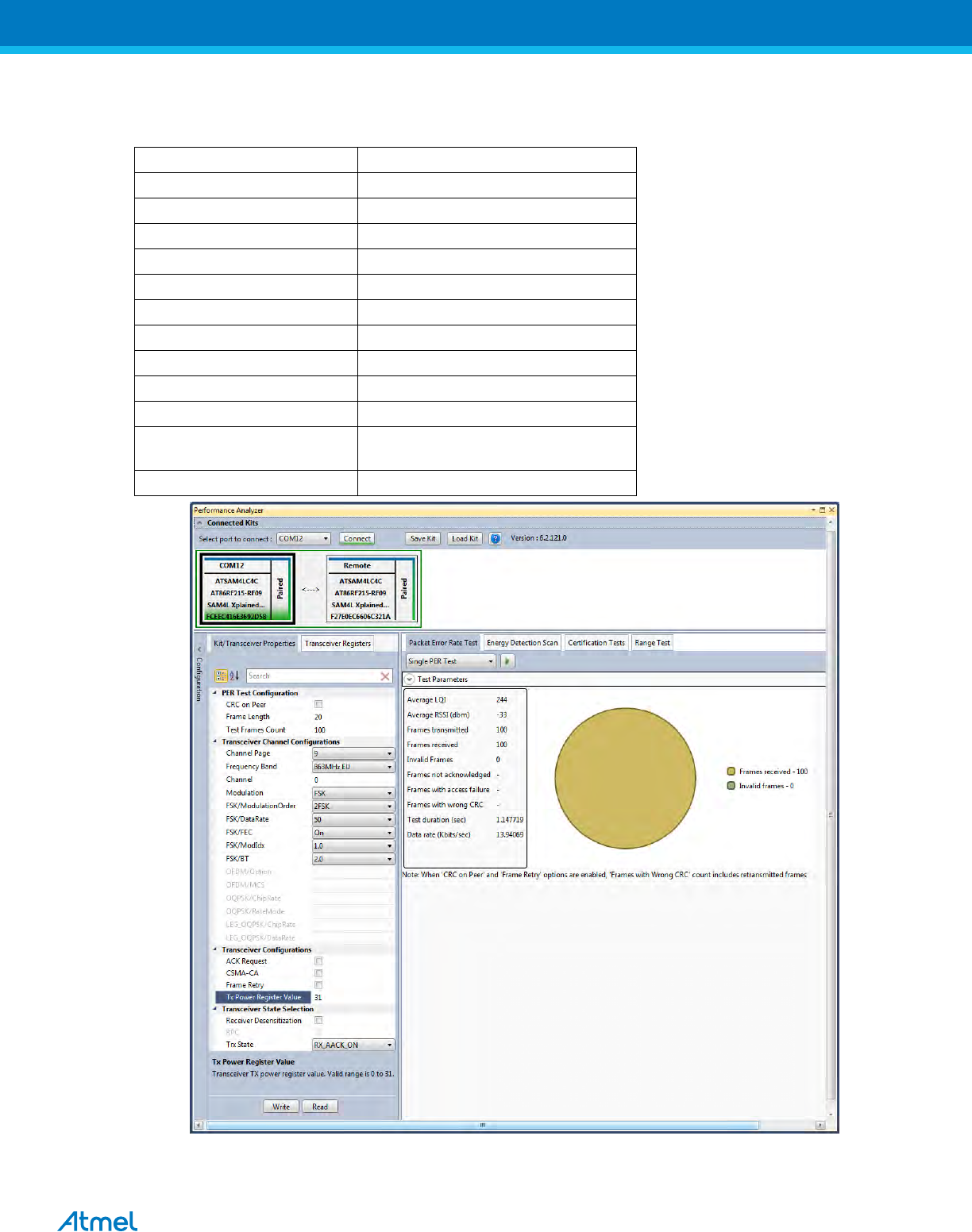
9.8 Rx Test - OFDM Option 2, MCS 3, 14dBm
Performance Analyzer configuration settings for transmit and receive test
Table 33:- Board setting
Frame Length
20
Test Frames count
100
Channel Page
9
Frequency band
2450MHz ISM Band
Channel
0 to 96 (2400MHz to 2483.5MHz)
Modulation
OFDM
OFDM/Option
Option2
OFDM/MCS
MCS 3
Tx Power Register Value
‘31’ for Max Power (14dBm)

ATREB215-XPRO-A Test User Manual
40
FCC Caution:
Any Changes or modifications not expressly approved by the party responsible for compliance could void the user’s
authority to operate the equipment.
This device complies with part 15 of the FCC Rules. Operation is subject to the following two conditions: (1) This device
may not cause harmful interference, and (2) this device must accept any interference received, including interference that
may cause undesired operation.
This module is intended for OEM integrator. The OEM integrator is still responsible for the FCC compliance requirement
of the end product, which integrates this module
The final end product must be labeled in a visible area with the following” Contains
FCC ID: VM4A092353
FCC Radiation Exposure Statement:
This equipment complies with FCC radiation exposure limits set forth for uncontrolled environment .This
equipment should be installed and operated with minimum distance 20cm between the radiator& your body.
This transmitter must not be co-located or operating in conjunction with any other antenna or transmitter.
IC Warning:
This device complies with Industry Canada licence-exempt RSS standard(s). Operation is subject to the following two conditions:
(1) This device may not cause interference, and
(2) This device must accept any interference, including interference that may cause undesired operation of the device.
Le présent appareil est conforme aux CNR d'Industrie Canada applicables aux appareils radio
exempts de licence. L'exploitation est autorisée aux deux conditions suivantes :
(1) l'appareil nedoit pas produire de brouillage, et
(2) l'utilisateur de l'appareil doit accepter tout brouillage radioélectrique subi, même si le brouillage est
susceptible d'en compromettre le fonctionnement.
The device been tested is compliance with RF field strength limits, users can obtain Canadian information on RF exposure and
compliance.The minimum distance from body to use the device is 20cm.
Le présent appareil est conforme
Après examen de ce matériel aux conformité ou aux limites d’intensité de champ RF,
les utilisateurs peuvent sur l’exposition aux radiofréquences et la conformité and compliance d’acquérir
les informations correspondantes. La distance minimale du corps à utiliser le dispositif est de 20cm.
Contains transmitter module IC: 11019A-092353
Where 11019A-092353 is the module’s certification number.

ATREB215-XPRO-A Test User Manual
41
Atmel Corporation
1600 Technology Drive
San Jose, CA 95110
USA
Tel: (+1)(408) 441-0311
Fax: (+1)(408) 487-2600
www.atmel.com
Atmel Asia Limited
Unit 01-5 & 16, 19F
BEA Tower, Millennium City 5
418 Kwun Tong Road
Kwun Tong, Kowloon
HONG KONG
Tel: (+852) 2245-6100
Fax: (+852) 2722-1369
Atmel Munich GmbH
Business Campus
Parkring 4
D-85748 Garching b. Munich
GERMANY
Tel: (+49) 89-31970-0
Fax: (+49) 89-3194621
Atmel Japan G.K.
16F Shin-Osaki Kangyo Bldg.
1-6-4 Osaki, Shinagawa-ku
Tokyo 141-0032
JAPAN
Tel: (+81)(3) 6417-0300
Fax: (+81)(3) 6417-0370
© 2012 Atmel Corporation. All rights reserved. / Rev.: Error! Reference source not found.
Atmel®, Atmel logo and combinations thereof, Enabling Unlimited Possibilities®, QTouch®, and others are registered trademarks or trademarks of Atmel
Corporation or its subsidiaries. ARM®, Cortex™ and others are registered trademarks or trademarks of ARM Ltd. Other terms and product names may be
trademarks of others.
Disclaimer: The information in this document is provided in connection with Atmel products. No license, express or implied, by estoppel or otherwise, to any intellectual property right is granted by this
document or in connection with the sale of Atmel products. EXCEPT AS SET FORTH IN THE ATMEL TERMS AND CONDITIONS OF SALES LOCATED ON THE ATMEL WEBSITE, ATMEL ASSUMES
NO LIABILITY WHATSOEVER AND DISCLAIMS ANY EXPRESS, IMPLIED OR STATUTORY WARRANTY RELATING TO ITS PRODUCTS INCLUDING, BUT NOT LIMITED TO, THE IMPLIED
WARRANTY OF MERCHANTABILITY, FITNESS FOR A PARTICULAR PURPOSE, OR NON-INFRINGEMENT. IN NO EVENT SHALL ATMEL BE LIABLE FOR ANY DIRECT, INDIRECT,
CONSEQUENTIAL, PUNITIVE, SPECIAL OR INCIDENTAL DAMAGES (INCLUDING, WITHOUT LIMITATION, DAMAGES FOR LOSS AND PROFITS, BUSINESS INTERRUPTION, OR LOSS OF
INFORMATION) ARISING OUT OF THE USE OR INABILITY TO USE THIS DOCUMENT, EVEN IF ATMEL HAS BEEN ADVISED OF THE POSSIBILITY OF SUCH DAMAGES. Atmel makes no
representations or warranties with respect to the accuracy or completeness of the contents of this document and reserves the right to make changes to specifications and products descriptions at any time
without notice. Atmel does not make any commitment to update the information contained herein. Unless specifically provided otherwise, Atmel products are not suitable for, and shall not be used in,
automotive applications. Atmel products are not intended, authorized, or warranted for use as components in applications intended to support or sustain life.