MICROCHIP TECHNOLOGY CY920C Network Media Module User Manual JukeBlox Technology 4 X SDK
MICROCHIP TECHNOLOGY INC. Network Media Module JukeBlox Technology 4 X SDK
UserManual.wiki
>
MICROCHIP TECHNOLOGY
>
CY920C User Manual
>
User Manual I
Contents
1.
User Manual
2.
User Manual II
3.
User Manual I
User Manual I
Navigation menu
Upload a User Manual
Namespaces
Wiki Guide
HTML
PDF
Info
Views
User Manual
Discussion / Help
Navigation

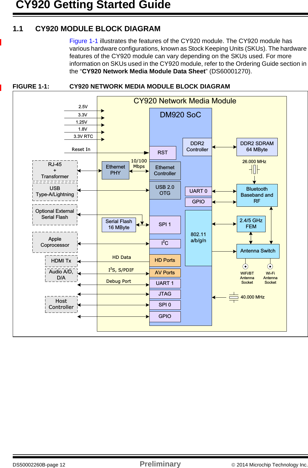
![CY920 Getting Started GuideDS50002260B-page 6 Preliminary 2014 Microchip Technology Inc.CONVENTIONS USED IN THIS GUIDEThis manual uses the following documentation conventions:DOCUMENTATION CONVENTIONSDescription Represents ExamplesItalic characters Referenced books MPLAB IDE User’s GuideEmphasized text ...is the only compiler...Initial caps A window the Output windowA dialog the Settings dialogA menu selection select Enable ProgrammerQuotes A field name in a window or dialog“Save project before build”Underlined, italic text with right angle bracketA menu path File > SaveBold characters A dialog button Click OKA tab Click the Power tabText in angle brackets < > A key on the keyboard Press <Enter>, <F1>Plain Courier New Sample source code #define STARTFilenames autoexec.batFile paths c:\mcc18\hKeywords _asm, _endasm, staticCommand-line options -Opa+, -Opa-Bit values 0, 1Constants 0xFF, ‘A’Italic Courier New A variable argument file.o, where file can be any valid filenameSquare brackets [ ] Optional arguments mcc18 [options] file [options]Curly brackets and pipe character: { | }Choice of mutually exclusive arguments; an OR selectionerrorlevel {0|1}Ellipses... Replaces repeated text var_name [, var_name...]Represents code supplied by uservoid main (void){ ...}Notes A Note presents information that we want to re-emphasize, either to help you avoid a common pitfall or to make you aware of operating differences between some device family members. A Note can be in a box, or when used in a table or figure, it is located at the bottom of the table or figure.Note 1: This is a note used in a table.Note: This is a standard note box.CAUTIONThis is a caution note.](https://usermanual.wiki/MICROCHIP-TECHNOLOGY/CY920C.User-Manual-I/User-Guide-2626455-Page-6.png)