MICROCHIP TECHNOLOGY RN4020 2.4GHz BLE MODULE User Manual
Microchip Technology Inc. 2.4GHz BLE MODULE
UserManual.wiki
>
MICROCHIP TECHNOLOGY
>
RN4020 User Manual
>
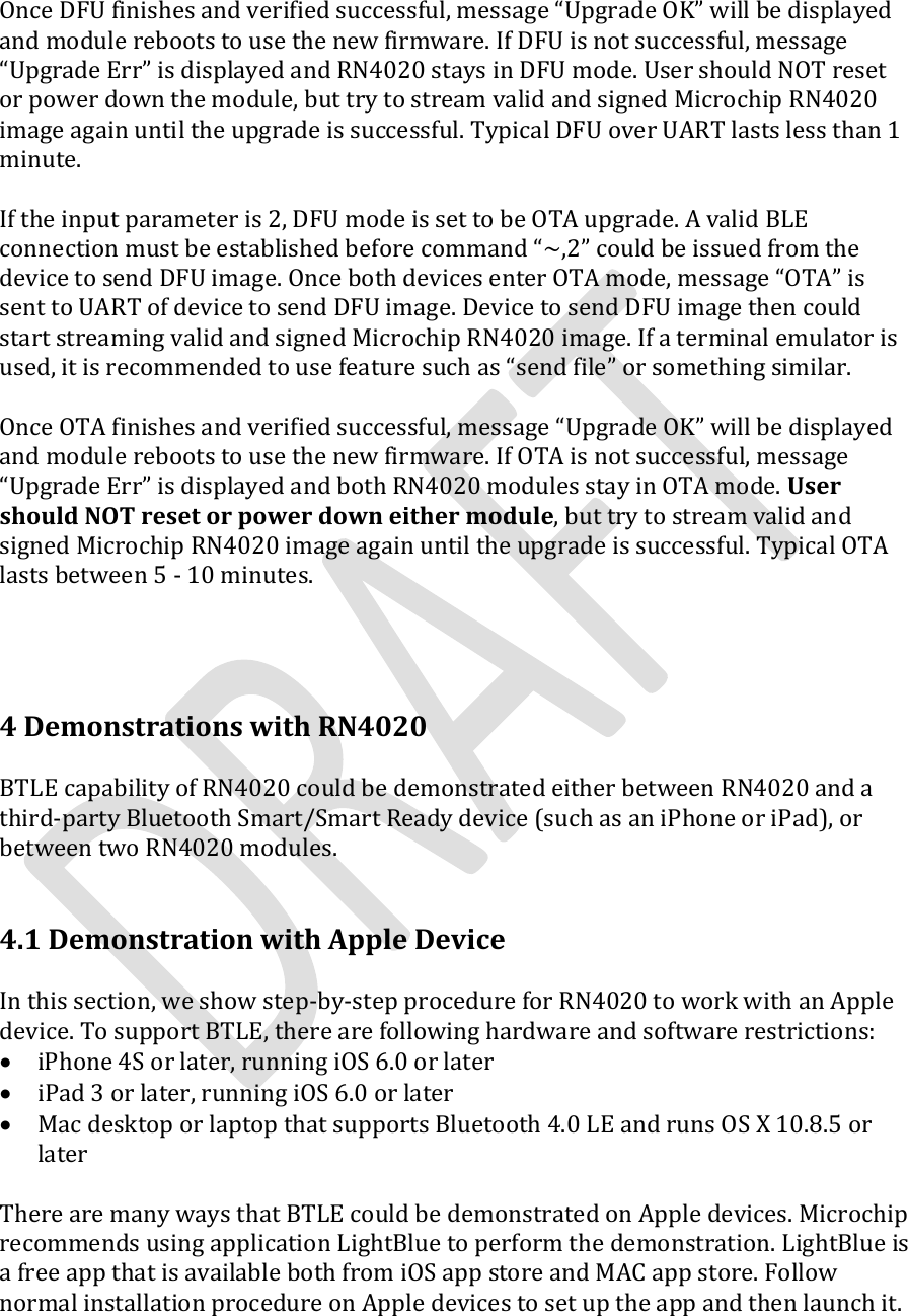
User Manual
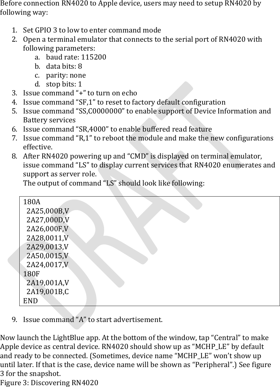
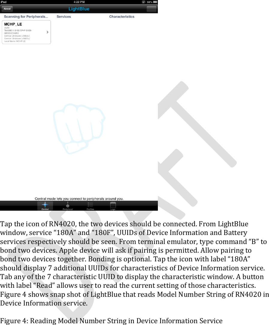
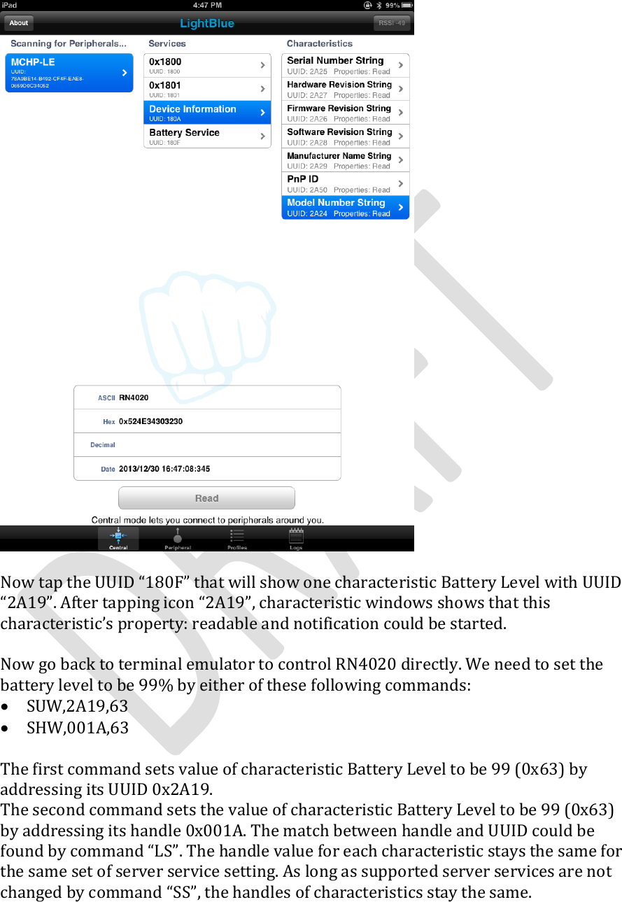
Contents
1.
User Manual
2.
User Mnaual Technical Spec.
User Manual
Navigation menu
Upload a User Manual
Namespaces
Wiki Guide
HTML
PDF
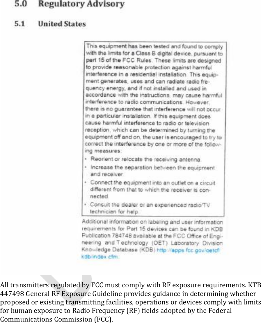
Info
Views
User Manual
Discussion / Help
Navigation