Microduino MIXC104E KIT-mCookie-Education User Manual Part 1
Microduino Inc. KIT-mCookie-Education Part 1
Contents
- 1. User Manual Part 1
- 2. User manual Part 2
User Manual Part 1

1

2
Table Of Contents
Scratch Introduction
Hardware Introduction
Rotating Motor Project
Motion Sensor Motor Project
Emoji Robot Project
Single Axis Steadicam Project
Airbag Project
Wired RC car Project
Safety Car Project
Delivery Truck Project
Obstacle Course Project
Edge Avoidance Car Project
Line Finding Car 1 Project
Line Finding Car 2 Project
3-25
26-46
47-68
69-88
89-108
109-127
128-147
148-167
168-187
188-208
209-229
230-250
251-271
272-294
A Guide Book For MIXC104E

3
With Scratch, you can program your own interactive stories, games, and animations
— and share your creations with others in the online community.
Scratch helps young people learn to think creatively, reason systematically, and work
collaboratively — essential skills for life in the 21st century.
Your students can use Scratch to code
their own interactive stories, animations,
and games. In the process, they learn to
think creatively, reason systematically, and
work collaboratively — essential skills for
everyone in today’s society.

4
Introduction
The Microduino MIX guide will show guide will walk you through an
introduction in the use of Arduino’s Scratch editor and then a number
of projects. With each project the challenge level increases so as to
expand your knowledge of coding and code thinking.
The process of coding also involves how to organize in your thinking
the process and sequence of events that will result in the correct oper-
ation of your project.
In our projects we use the Arduino ‘Scratch’ editor to construct and ex-
ecute code to drive the hardware of projects. Scratch has become one
of, if not the, most popular coding tool today.
As you read the introduction of Scratch keep in mind that the basic ar-
eas of the scratch editor uses many similar terms used in the parts of
a stage play. It refers to stages, scripts, costumes, backdrops and so
on. This is meant to help us create a mental image of what we doing.
Beyond this we get into the more technologial terms of technology.

5
Installation
6
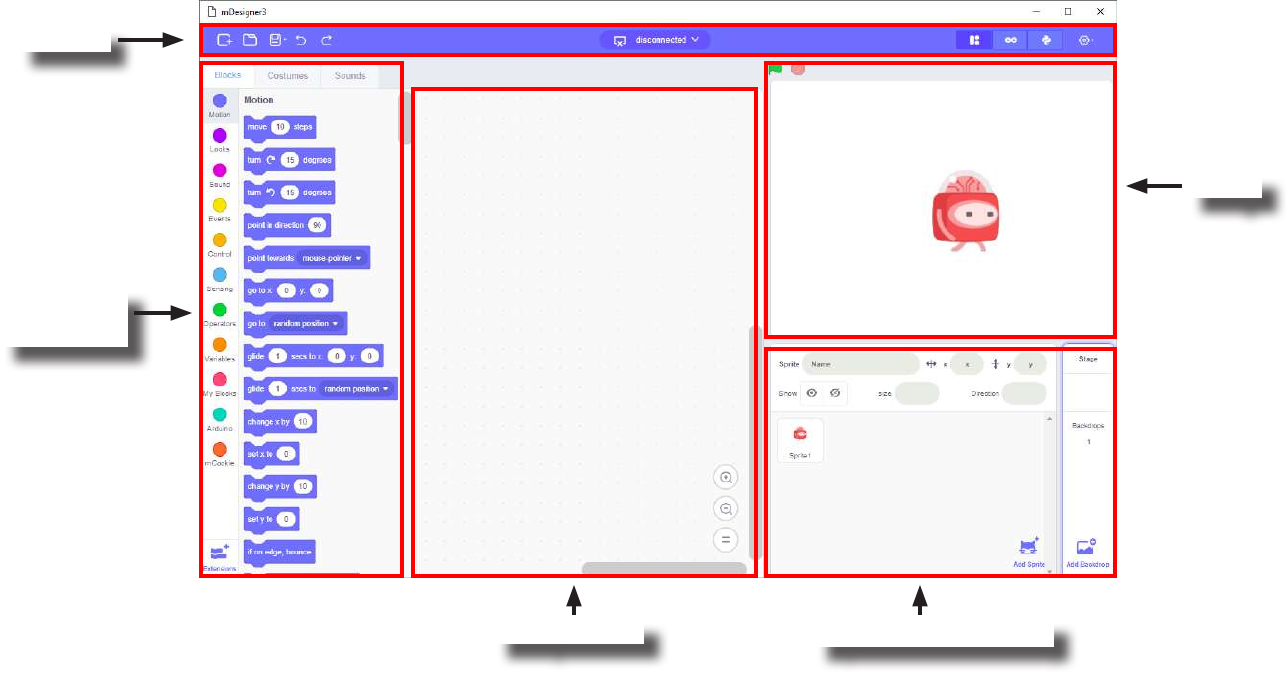
The Interface
Toolbar
Scripts Area
Palettes &
Panes
Sprites & Backdrop
Stage
7
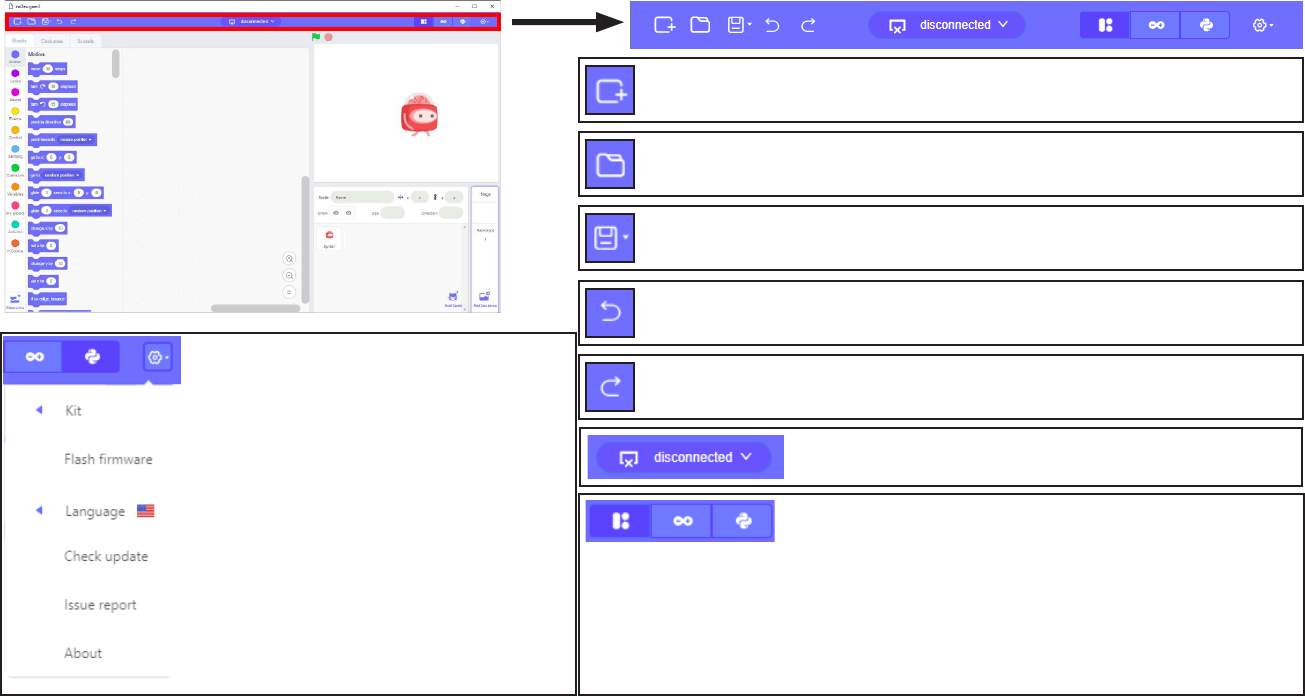
Toolbar
The Tool Bar in Scratch provides many useful functions and conguration options. Below is a quick overview of each
menu item. Some terms and phrases will be explain later.
New Project - creates a new blank project.
Open Project - open a saved project.
Save / Save As - save / save as the current project.
Undo - undo the most recent change in the project.
Redo - redo the most recent undo in the project.
Settings - various conguration settings
for Scratch.
• Kit - select a Microduino kit, which
shows enables dierent blocks.
• Flash rmware - ash the required
rmware onto the hardware to use
Scratch / Live mode.
• Language - select language.
• Check update - check for and update
to the latest Scratch version.
• Issue report - submit a bug report.
• About - information on the version of
Scratch.
Mode Selection - select dierent control modes for Scratch:
• Scratch / Live mode - control MIX hardware in real time
using Scratch blocks. MIX hardware requires a constant
connection to a PC in order to function.
• Arduino Mode - compiles and uploads codes onto MIX
hardware. Once a program is uploaded, MIX hardware can
run independently without a PC connection.
• Text Coding Mode - text based programming. Currently
under development.
Serial Port - select serial port for usage or program-
ming of MIX hardware.
8
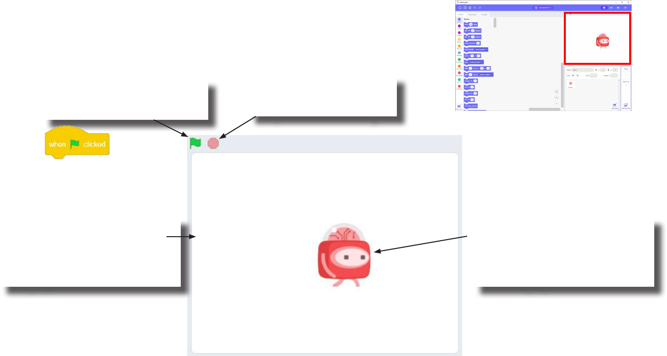
Stage
Scratch can be thought as a school play. The Stage is where the viewer sees the
play. Sprites can be thought as actors or characters in a play. Backdrop is the
background. Together they make the Stage. Below is a quick overview. Some
terms and phrases will be explained later.
Stop Sign:
When clicked, stops all
Scripts that are running.
Green Flag:
When clicked, all “When Green
Flag Click” blocks activates.
Backdrop:
Is the background of the stage.
There can only be one Backdrop.
It can be change and you can also
design your own.
Sprite:
Sprites can be thought as actors
or characters. There can be multi-
ple Sprites on the Stage. You can
also design your own.
The Stage includes Sprite(s) and a Backdrop.
9
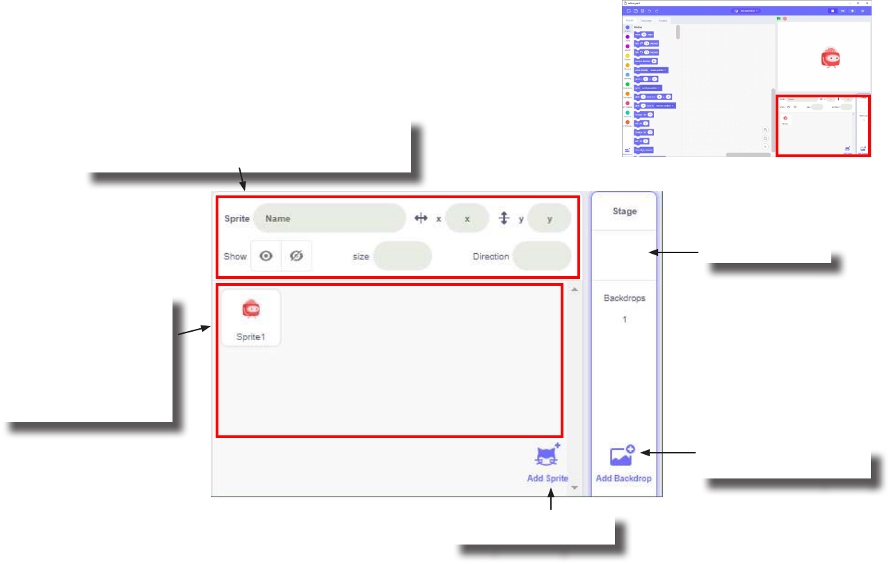
Sprites & Backdrop
This section allows you to select, edit and create Sprites and Backdrops. Select-
ing a Sprite or Backdrop is done by clicking on it from this section. Below is a
quick overview. Some terms and phrases will be explained later.
Sprites in your project
are located here. There
can be multiple sprites in
a project. New projects
automatically have one
Sprite included. Its name
is Corey.
Add a new sprite from
the sprite library.
Add a new backdrop
from the backdrop library.
Current backdrop.
When a sprite is selected. Edit the sprite name,
sprite position on the stage, visibility, size of the
sprite and the angle of the sprite.

10
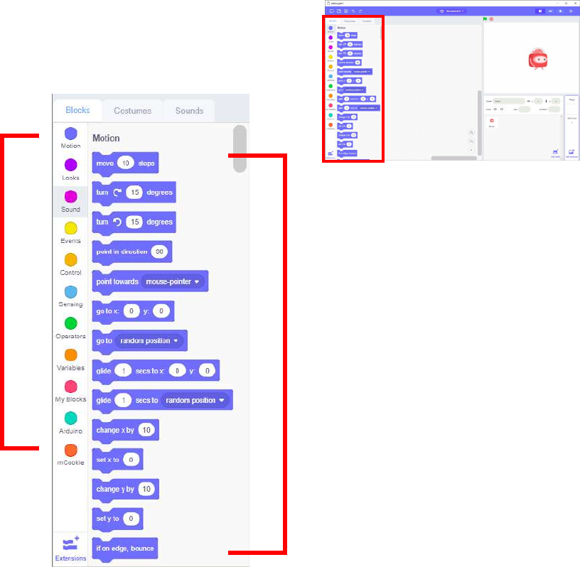
Palettes & Panes
This section of the interface contains the Sprite Pane, Costume Pane / Backdrop Pane, and Sound Pane. You can switch
between the panes by clicking on the appropiate tabs.
Click to activate
Script pane.
Click to activate Costumes
or Backdrops Pane.
Click to activate
Sound pane.
11
Script Pane
The Script Pane contains the tools you need to make your Sprite or Backdrop
do things. A Script can be thought of as the instructions that your Sprite or Back-
drop follows, similar to a school plays’ script which instructs the actor what to do.
Some terms and phrases will be explained later.
Block Categories:
Blocks are sorted to dierent
categories for quicker access.
Each category has its own color
and the Blocks contained within
are the same color. For example,
“Motion” Blocks are all purple.
Blocks:
Blocks are instructions for your
Sprite or Backdrop to follow.
There are many Blocks each with
their own type. Blocks are cate-
gorized into dierent categories.
12
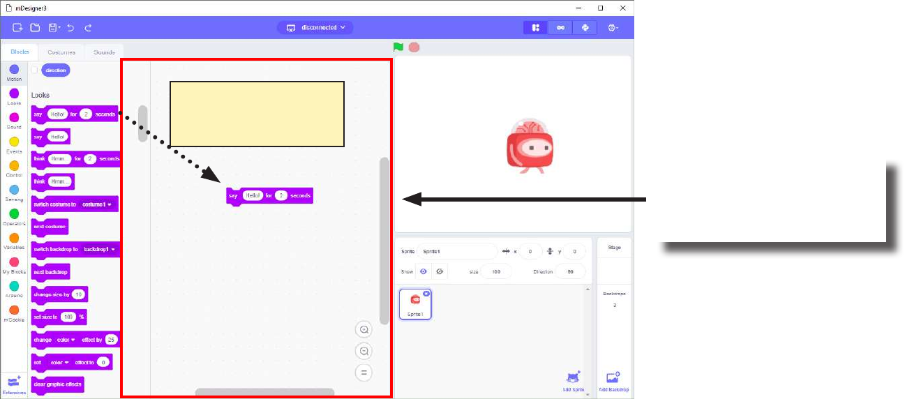
Scripts Area
The Scripts Area is one of the most important parts of the Scratch interface. It allows you to create and assemble the
Script for your currently selected Sprite or Backdrop. You can drag Blocks from the Scripts Pane into the Scripts Area to
assemble your Script. Each Sprite or Backdrop has its own personal Scripts Area. A Script can be thought of as the in-
structions that your Sprite or Backdrop follows.
Scripts Area:
Assemble your Script for your
currently selected Sprite or
Backdrop.
Assemble Scripts by
dragging Blocks into
the Script Area.
13
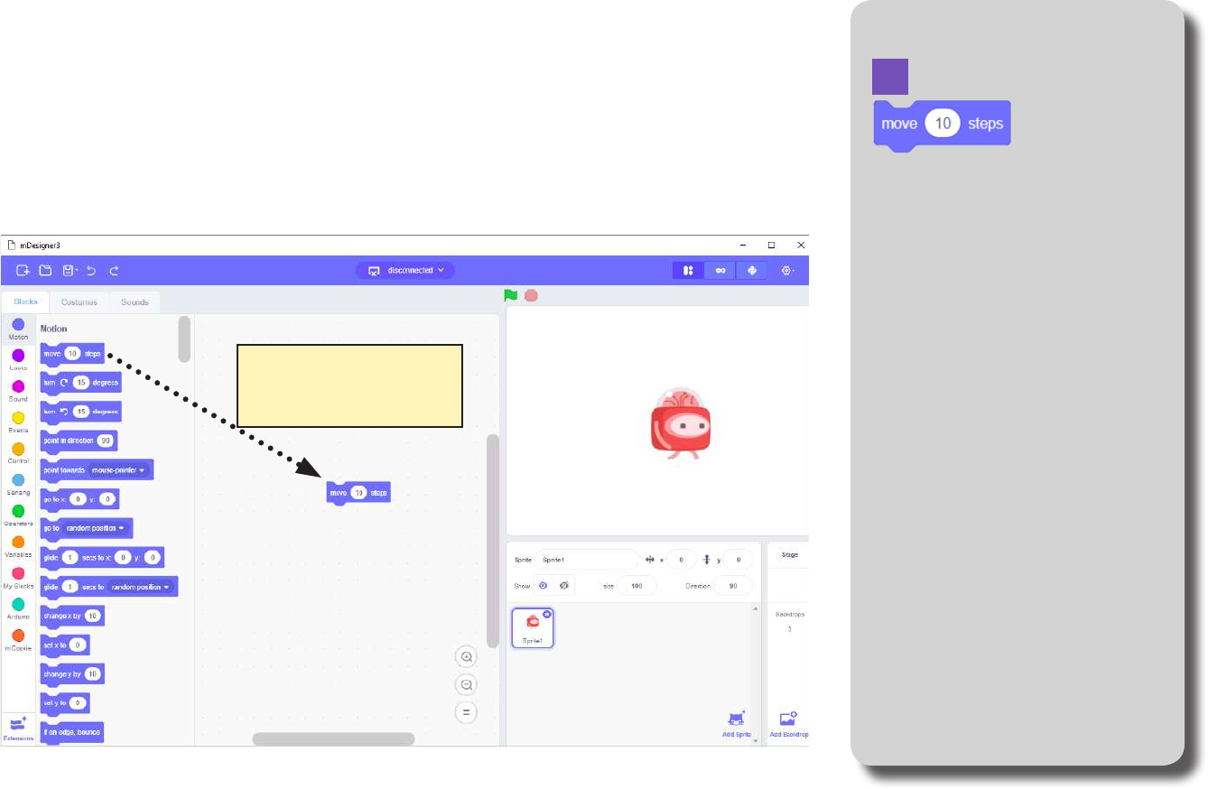
Exercise: “First Steps” Block Locator
Let’s create your very rst project! Let make Corey take its very rst steps.
Assemble the Script below by dragging the Blocks you need from the Sprite Pane
into the Scripts Area. The “Block Locator” sidebar is there to aid you in nding the
blocks you need you need quickly. Use it for your convenience!
Assemble Scripts by
dragging Blocks into
the Script Area.
Motion
14
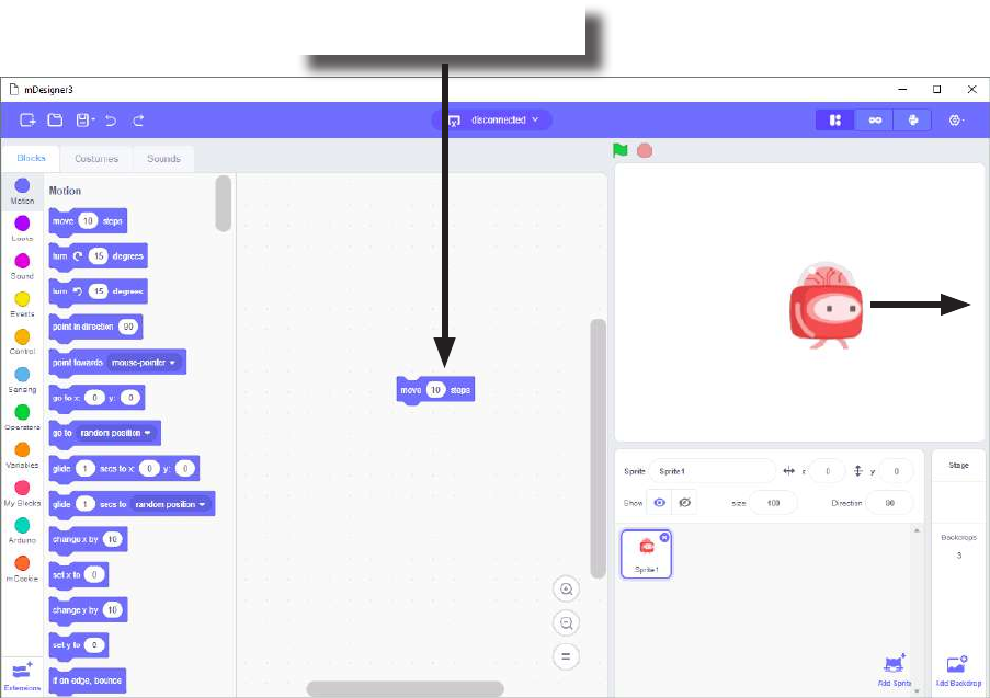
Exercise: “First Steps”
Now click on the Block you just added to the Scripts Area. What happens to
Corey on the stage? It moved 10 steps to the right!
Click on any colored part
of the block to activate it.

15
Types of Blocks
There are dierent types of Blocks which have dierent shapes. Each shape has a dierent purpose and is
intended to aid in assembling Scripts.
Hat blocks are the blocks that start every script. They are shaped with a rounded top
and a bump at the bottom — this is so you can only place blocks below them.
Stack blocks are the blocks that perform the main commands. They are shaped with a
notch at the top and a bump on the bottom — this is so blocks can be placed above and
below them.
Boolean blocks are the conditions — they are either true or false. It’s like asking your
friend: “Does 2 + 2 = 4?”, and they would either tell you “Yes” or “No”. Boolean blocks
have a hexagonal shape.
Reporter blocks are the values. Shaped with rounded edges, Reporter blocks can hold numbers
and strings. It is like asking a friend, for example, “What is 2 + 2?”, and they would answer “4”.
It is not just equations however, it can report a variable, for example, “What is your age?”. They
may answer: “15”.
C blocks are blocks that take the shape of “C’s”. Also known as “Wrap blocks”, these
blocks loop the blocks within the Cs or check if a condition is true.
Cap blocks are the blocks that end scripts. They are shaped with a notch at the top and
a at bottom — this is so you cannot place any blocks below them.
Source: https://wiki.scratch.mit.edu/wiki/Blocks
16
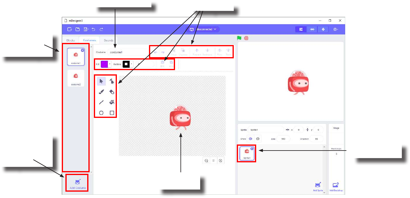
Costume Pane
When a Sprite is currently selected, the middle tab becomes the Costume Pane. This section allows you
to design Costumes for your currently selected Sprite. Costumes can be thought of as a dierent image /
appearance for your Sprite. It is useful to use Costumes when creating animations for your Sprite or if you
want your Sprite to change its appearance.
When a Sprite
is selected.
Add a new
costume for the
currently select-
ed Sprite.
Costumes for
the currently
selected Sprite.
Editing tools.
Costume’s name.
Costume’s
Appearance
17
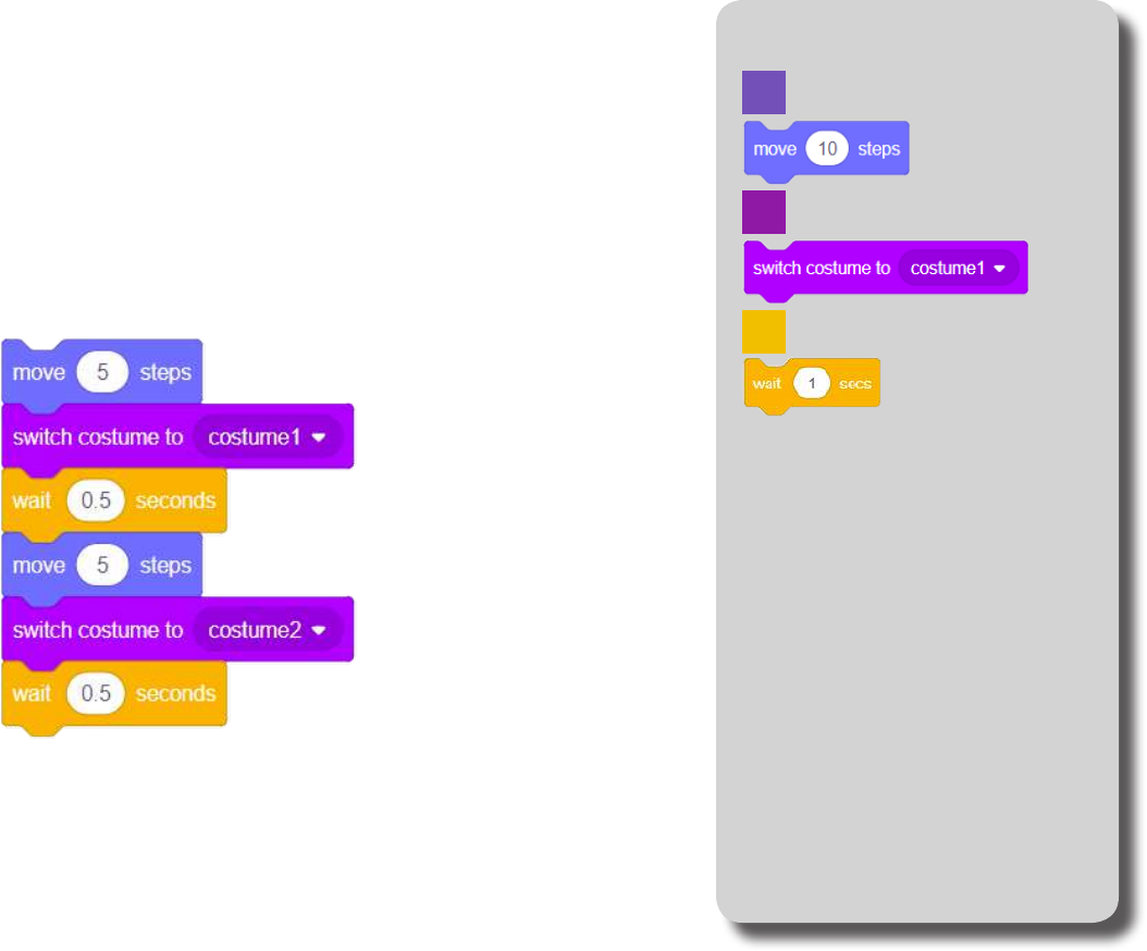
Exercise: “Second Steps” Block Locator
How can we animate Corey to look like it is walking?
We change Corey’s costume to look like it is taking steps.
Assemble the Script below:
Motion
Looks
Control
18
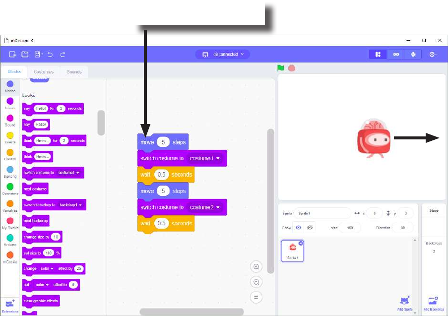
Click on any color portion of the Script. What does Corey do?
Corey walks with an animation! Click repeatedly to make Corey perform the animation over and over again.
Click on any colored part
of the block to activate it.
Exercise: “Second Steps”
19
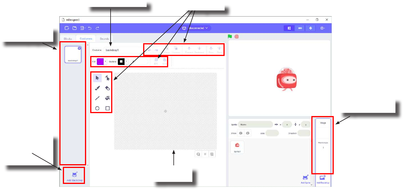
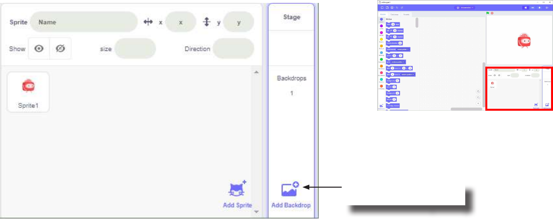
When Backdrop is currently selected, the middle tab becomes the Backdrops Pane. This section allows
you to design Backdrops. It is useful to have multiple Backdrops if you want to change the background for
your project.
When a Back-
drop is selected.
Add a new
Backdrop to the
project.
Backdrops in the
current project.
Editing tools.
Backdrop’s name.
Backdrop’s
Appearance
Backdrop Pane
20
Corey doesn’t like walking in a blank white space. Corey wants to walk in the park!
How can we make Corey walk in a park?
We can change the Backdrop to a scenery of a park.
But rst we need to create a Backdrop of a park.
Creating a Backdrop
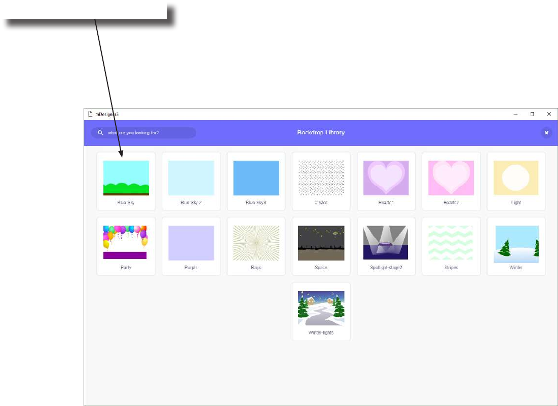
Add a new backdrop
from the backdrop library.
21
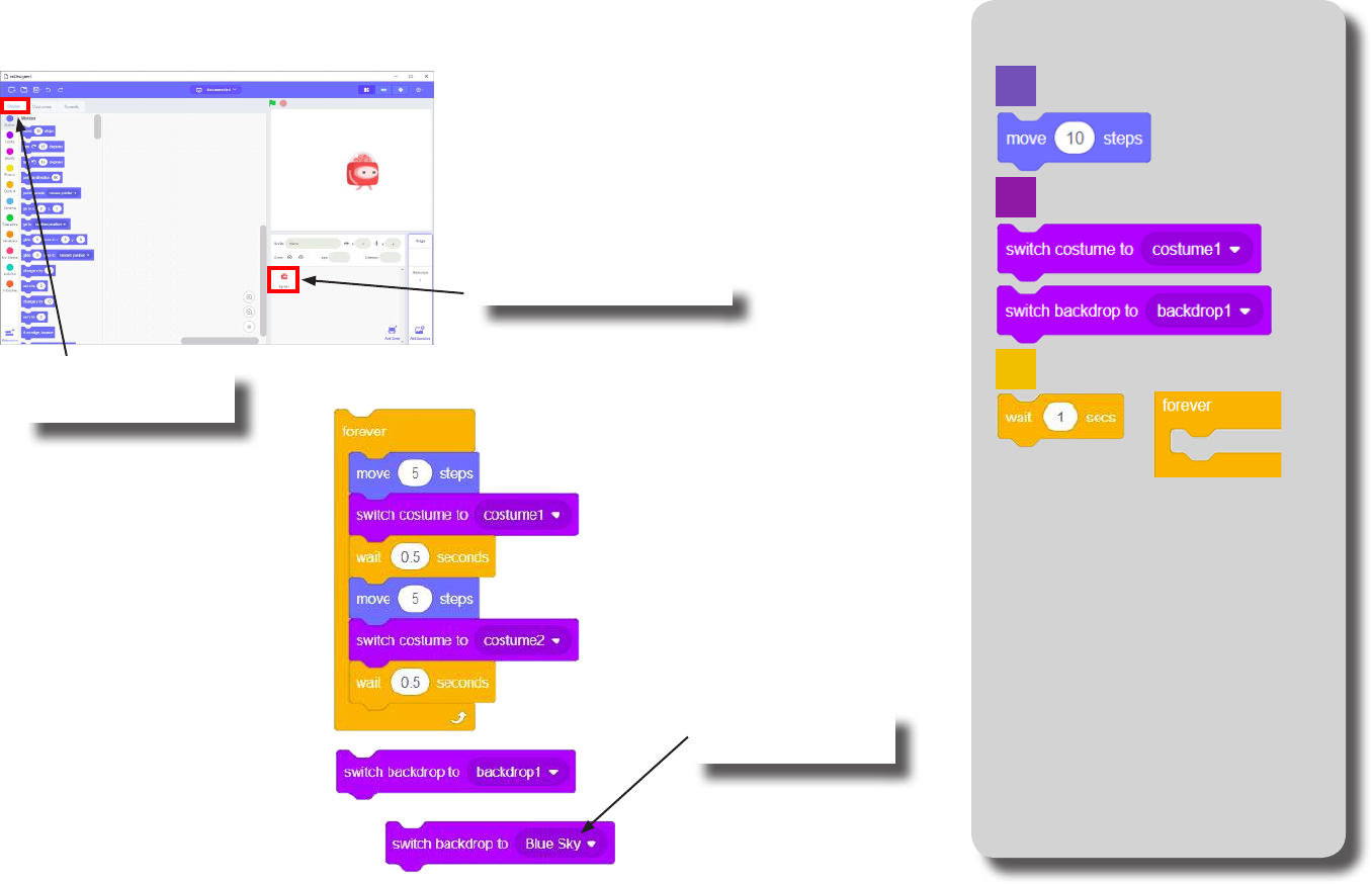
Creating a Backdrop
Select a backdrop for the park.
22
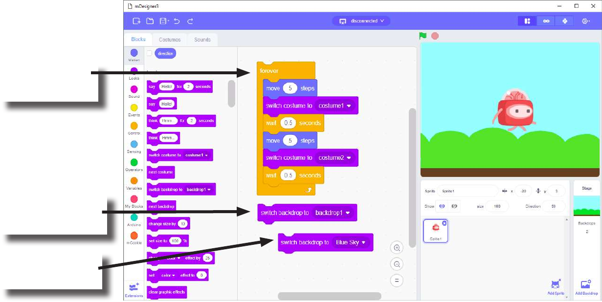
Exercise: “A Walk in the Park” Block Locator
Don’t forget to switch back to Corey by
selecting Corey and then switching to the
Scripts Pane.
Once you have created your new Backdrop,
assemble the blocks below:
Motion
Looks
Control
1. Click to select Corey.
2. Click to switch to
Switch Pane.
Set to your newly
Created Backdrop.
23
Exercise: “A Walk in the Park”
Click and Corey
will start walking
forever.
Click to change the
Backdrop to the
default white one.
Click to change the
Backdrop to your
custom one.
24
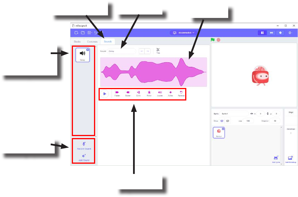
Sound Pane
List of sounds
for the currently
selected Sprite or
Backdrop.
New sound
creating options.
Click to activate
Sound pane. Sound’s name.
Editing and
playback tools.
Sound wave
appearance.

25
This chapter is intended to give a basic understanding of how to use Scratch when creating projects in
the MIX kits. There are a vast amount of topics to learn about Scratch which are outside the scope of
this product. Many resources can be found online to learn more about Scratch!
Further Learning
Links
• https://scratch.mit.edu/

26
Hardware Mix 4
27
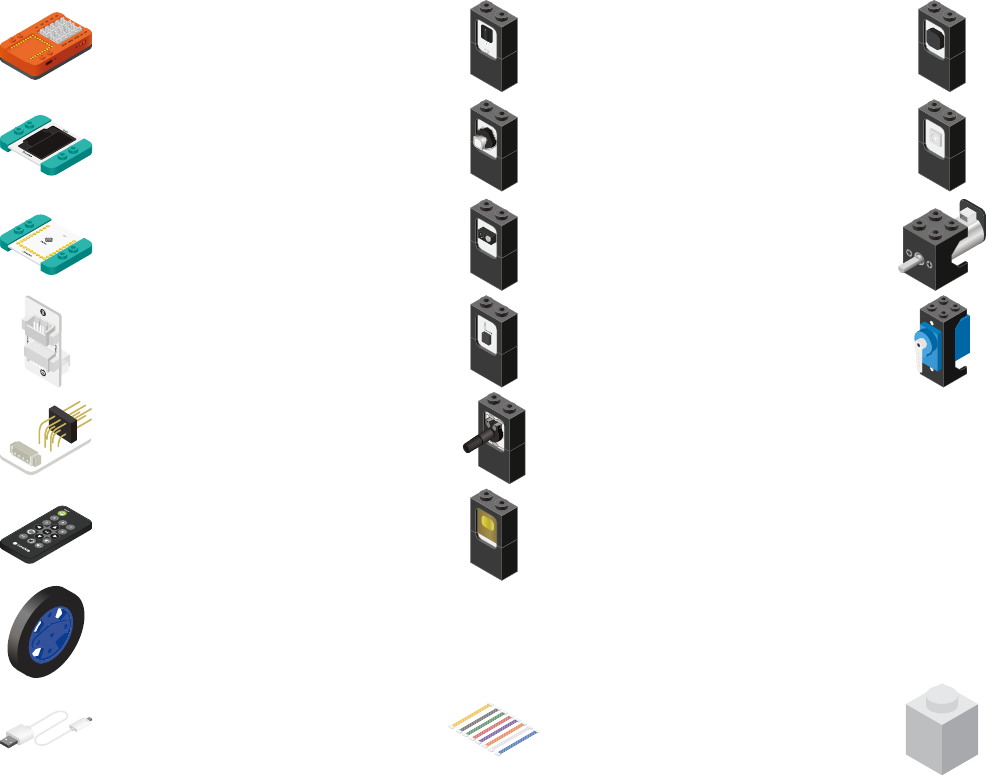
MIX 4 Kit Contents
1x Color LED
1x Touch Button
1x USB Cable 24x Hub Connector Cables
Sensors Trinkets
4x Line Finder
2x Servo
2x Potentiometer
1x Motion
1x Motor Controller
2x IO Splitter
1x Remote Control
1x IR Receiver
2x Wheel
2x Motor
Building Blocks
1x mCenter+
1x OLED
1x Servo Connector
1x Joystick
1x Buzzer
28
Scratch and mCookie
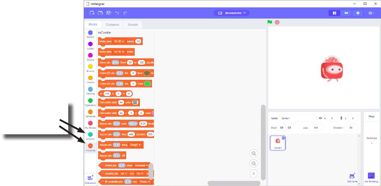
The Microduino version of Scratch contains special added features which enables the use of mCookie modules. The
Blocks under the Category Block called Arduino and mCookie, adds support to use mCookie modules.
Blocks can be found
under the category
Arduino and
mCookie.
29
Scratch and mCookie
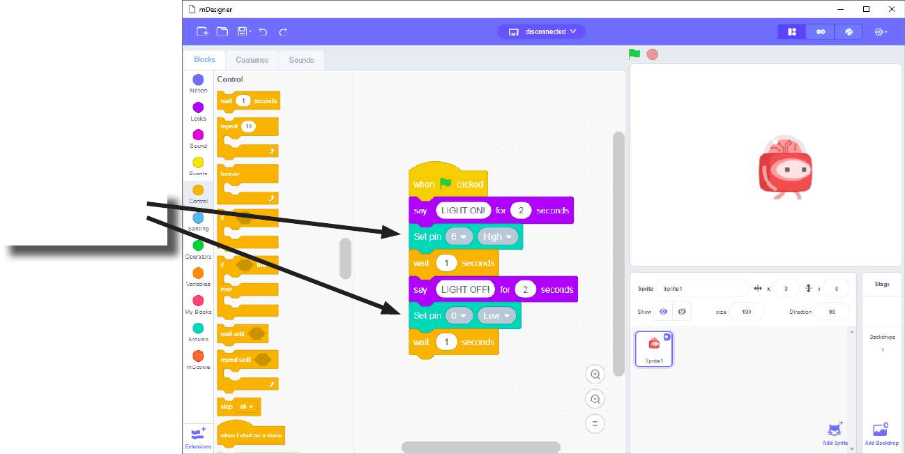
You can use the Blocks under the Arduino and mCookie category in your Scripts as you would use any other Block.
Arduino and
mCookie Blocks.

30
mCookie Series
Microduino’s mCookie series is designed for ease of use. The series is modular, stackable, magnetized, easily connect-
able and building blocks compatible. It makes assembling a project quick and easy.
Modular Stackable and Magnetized Building Block Compatible
31
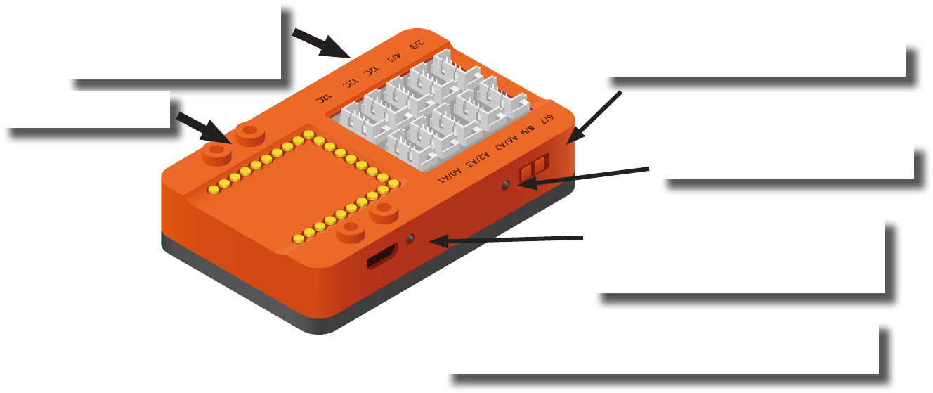
mCenter+
Is a ve-in-one module which contains:
• Li-ion Battery: battery pack to power your projects which can be recharged via the USB port.
• mCookie Core+: a tiny central processing unit (CPU), which is the brains of your projects.
• USB Programmer: programs the Core+ module and acts as a serial communication bridge between your computer
and Core+ module.
• Bluetooth Upload: similar to the USB programmer, but works wirelessly over Bluetooth communication.
• Hub: connects various modules such as sensors, trinkets, and other modules to your projects. These modules can
then be accessed by the Core+ module.
MicroUSB Port: To charge the battery
and upload programs to a embedded
Core+ module when connected to a
computer.
IMPORTANT: When uploading programs, make sure the
red LED is on, which means the modules are receiving
power.
Power Switch: Turn on or o the battery
to supply power to the modules.
LED Power Indicator: Indicates if
mCenter is on or o.
Hub Connectors:
Connect sensors or trinkets
to mCenter+ with a Hub
Connector Cable.
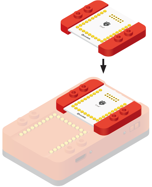
Module Pad: Stack
modules to mCenter+.
32
Embedded Core+ Module
mCenter+ contains an embedded Core+ module. The Core+ module is the brains of your projects. It is a tiny central pro-
cessing unit (CPU) that you can program or control. It is capable of controlling or sensing information from other modules.
It is programmable when connected to a computer.
33
mCenter+’s Hub
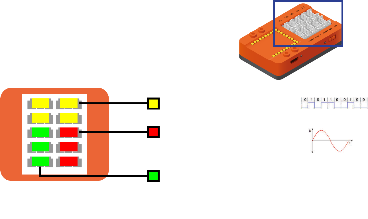
mCenter+ incorporates a Hub. The Hub connects various modules such
as sensors, trinkets, and other modules to a project. These modules
can then be accessed by the embedded Core+ module. The Hub has
10 connection header ports. Each connection header has support for
dierent sets of features. Some headers may support a feature, while
another may not.
2/3 6/7
8/9
I2C A2/A3
I2C
I2C
4/5
A6/A7
A0/A1
I2C
I2C
I2C
A6/A7
A2/A3
A0/A1
2/3 6/7
4/5 8/9
Digital signals produce only a o (LOW) or
on (HIGH) state. There is no “middle” state
between the two.
Analog signals are continuous and fea-
ture many “middle” points. They look like
smooth curves.
IIC is a type of serial communication interface. It is more ad-
vanced than digital and analog signals. Under IIC, messages
are exchanged and understood between communicating mod-
ules. Modules such as the OLED screen, temperature & humid-
ity sensor, real time clock (RTC) module and other modules use
this method of communication.
34
Color LED
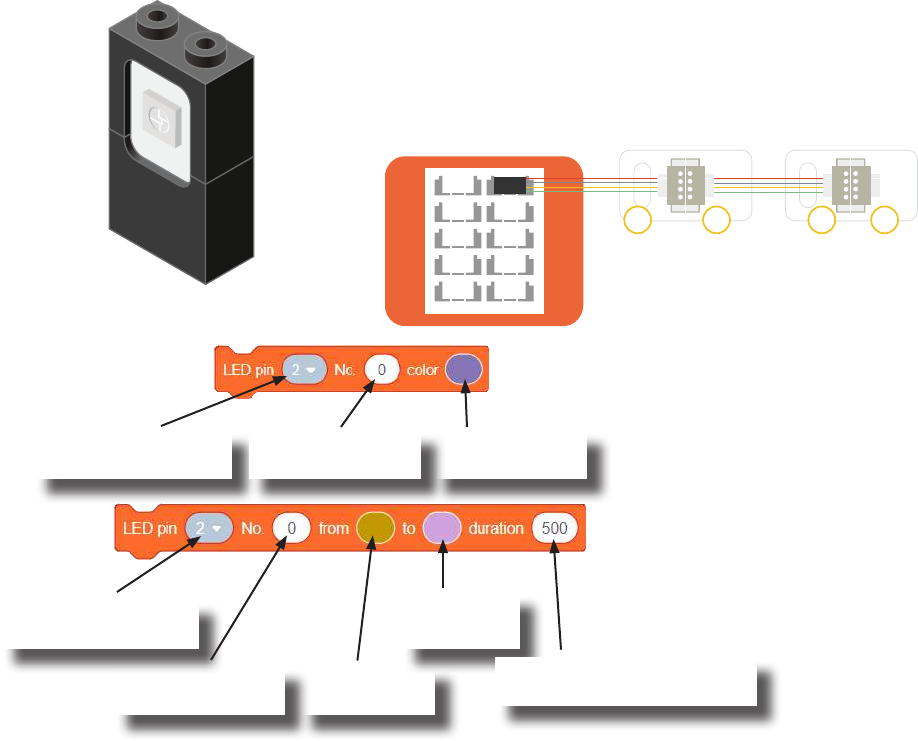
The Color LED is a LED composed of 3 smaller LEDs which emit red, green, and blue.
Each color’s brightness value can be congured individually. This can produce a wide
variety of colors. It is controlled over a special communication protocol which is dier-
ent from the basic “Digital Output” (used by Single-Color LED).
Usage
This block congures what color a particular Color LED
displays.
Hub pin the 1st Color
LED is connected.
Transition from
this color.
Transition to
this color.
Color LED - Color Select block
Color LED - Color Transition block
This block causes a particular Color LED to transition from one
color to another color under a time span. (Note: This block must
complete its transition before proceeding to the next block in the
script.)
Index of the Color
LED to congure.
Color to change
the Color LED to.
Hub pin the 1st Color
LED is connected.
Set duration (in milliseconds)
for the transition.
• The Color LED connected
directly to the Hub is index 0.
• The Color LED connected
next in the chain is index 1.
• And so on.
Indexing
2/3
8/9
I2C A2/A3
I2C
I2C
4/5
A6/A7
A0/A1
6/7
IN INOUT OUT
Index of the Color
LED to congure.
ColorLED
Index: 0
ColorLED
Index: 1
35
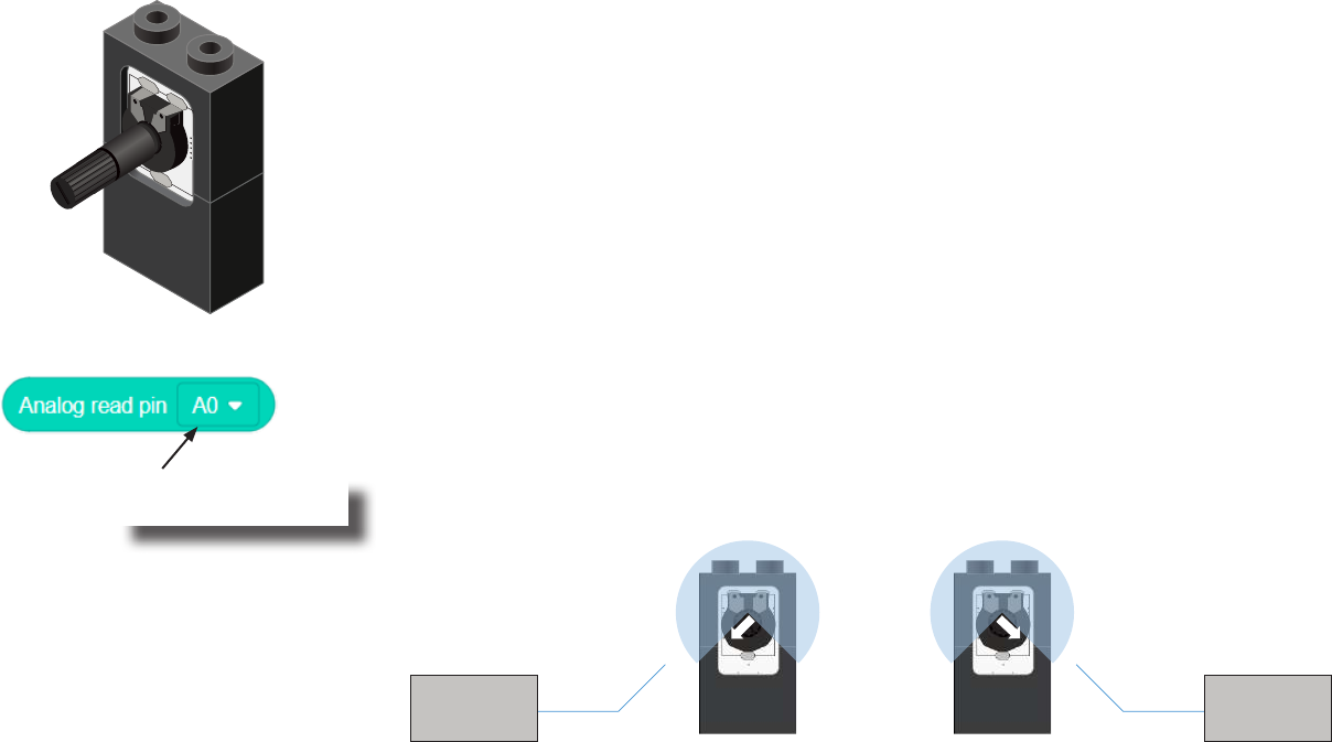
A Potentiometer is a input module which can be turned or rotated right or left. Based
on the position of the knob, it produces a dierent signal value for the Core module to
read. It must be connected to an analog port (ports denoted with “A”).
Analog Read block
This block returns the value from the Potentiometer. A value between 0 and 1023 is returned.
If the potentiometer is turned all the way to the left, it produces a 0 value. If it is turned all
the way tot the right, it produces a 1023 value. In the middle it produces a value around 512.
Pin the Potentiometer
is connected to.
0 1023
Potentiometer
36
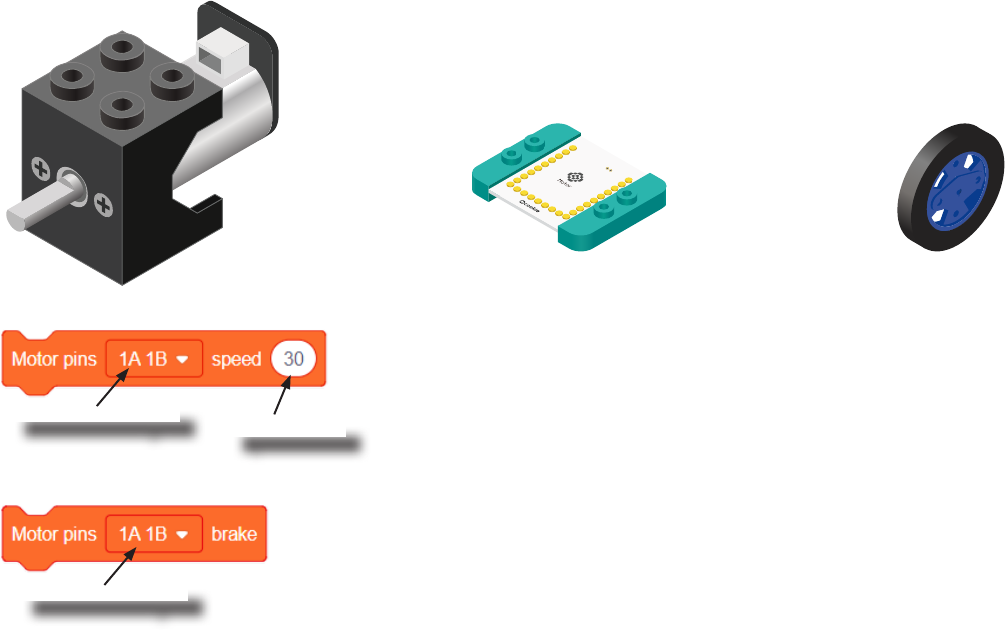
Motor
A Motor is a electrical machine which converts electrical energy to mechanical energy. It
is capable of rotating clockwise and counter clockwise. It is controlled by a Motor Con-
troller. A Motor Controller can control up to 2 Motors. A Wheel can be attached to the
Motor.
Motor Controller Wheel
Motor - Set Speed block
This block sets the speed of the motor. Positive values turns the Motor in one direc-
tion. While negative values turns the Motor in the opposite direction. A value of 0
stops the Motor. Values between -255 and 255 are accepted. 255 is maximum clock-
wise speed. -255 is maximum counter-clockwise speed.
Motor - Brake block
This block sets the speed to 0 to stop the Motor.
Motor to congure.
Motor to congure.
Speed to set.
37
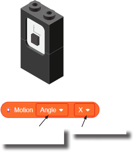
Motion
The Motion module is a triple axis accelerometer and gyroscope.
It is capable of measuring on the X, Y & Z axis the:
• Angle
• Acceleration
• Angular velocity
It uses the “I2C” communication protocol and must be connected to and “I2C” port on
mCenter+.
Motion - Read block
This block reads data from the Motion module. It is capable of retrieving the angle,
acceleration and angular velocity on the X, Y or Z axis.
Angle, acceleration, or
angular velocity to read.
On the X, Y or Z axis.
38
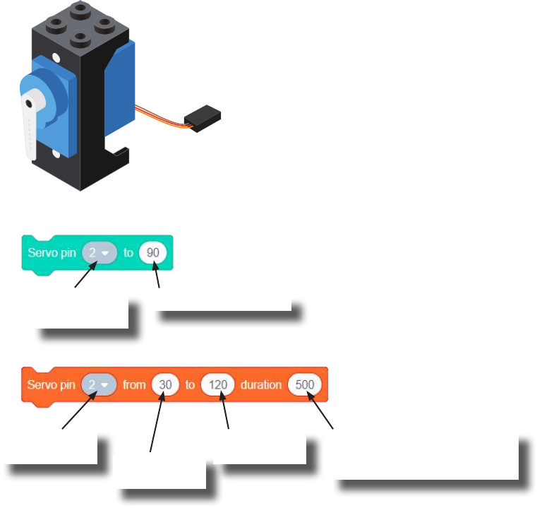
Servo - Set Angle block
Servo - Move From-To Angle block
Sets the angle of the Servo. Quickly moves (as fast as possible) to the desired angle.
Sets the angle from the starting angle to the target angle. This move-
ment is performed in the specied duration time.
Pin the Servo is
connected to.
Angle to set Servo to.
Pin the Servo is
connected to. Starting angle
of Servo.
Target angle
for Servo.
Time in millisecond to move
from starting angle to target
angle.
A Servo is an actuator which consist of a motor and other electronic components which
allows for precise angle adjustments of the attached horn. The servo included in the kit
has an adjustable angle range between 0 and 180 degrees.
Servo
39
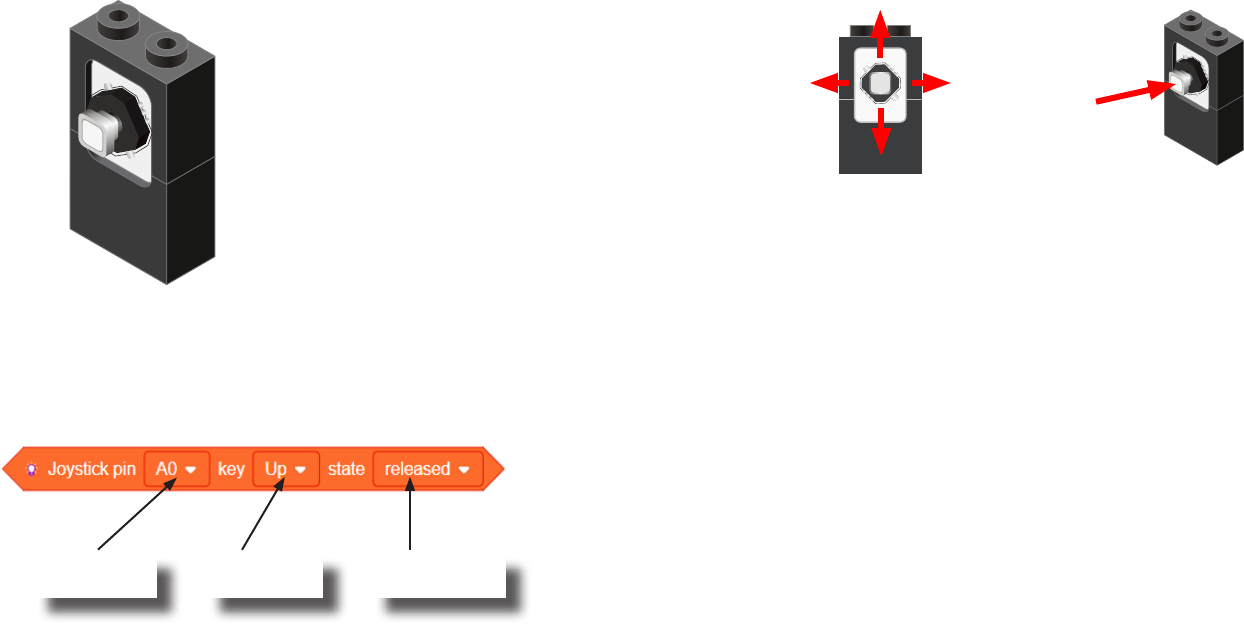
A Joystick is an input module (sensor)
which can sense if the stick is in the
up, down, left or right positions.
In addition, it can sense if it being
pressed (pressing directly on stick).
Up
Left Right
Down
Press
Usage
The Joystick must be connected to an “Analog Read” compatible pin.
These are the pins prexed with an “A” (pins A0 to A7).
Joystick State block
On the dened Joystick pin, if the stick’s position (up, down, left,
right or center (pressed)) matches the state (released, pressed or
pressing), then this block returns TRUE.
Otherwise, this block returns FALSE.
Pin Joystick is
connected to.
Stick position
to check.
Stick position’s
state to match.
Joystick
40
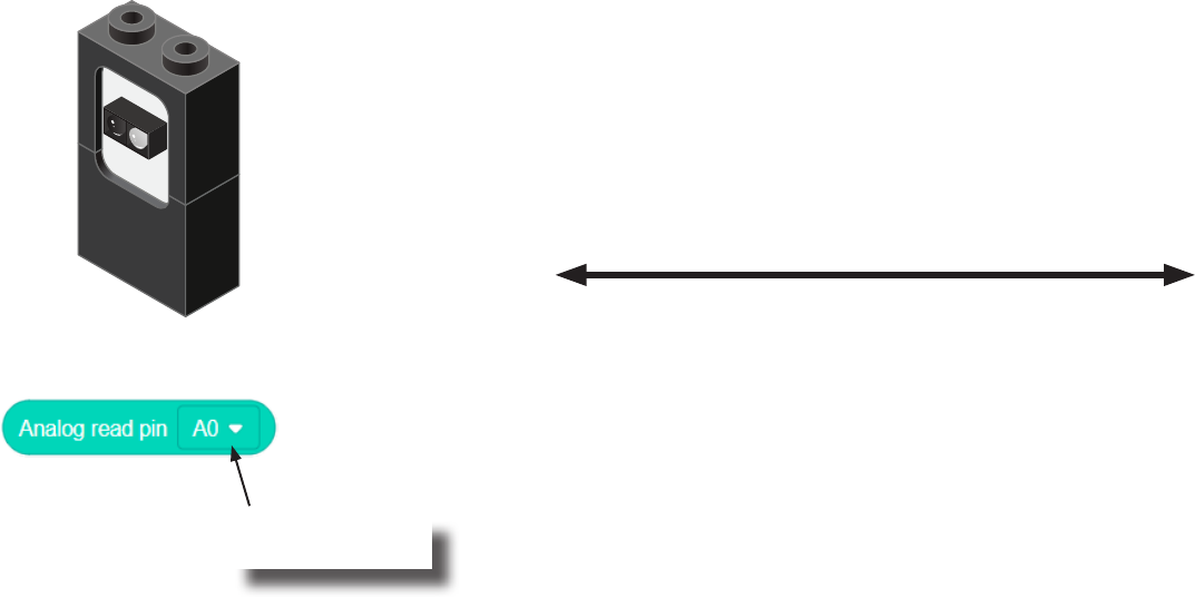
The Line Finder module is able to detect reectivity or gray level of a surface. In gen-
eral, darker or less reective surfaces produces a higher value. While a lighter or more
reective surface produces a lower value. It must be connected to a pin with an
“A” prex (A0/A1, A2/A3, A6/A7).
Analog Read block
This block returns the value that the Line Finder detects. A value between 0 and 1023 is
returned.
Pin that Line Finder
is connected to.
0 1023
Darker,
less reective surfaces.
Lighter,
more reective surfaces.
Surface Reectivity
Value Returned
Line Finder
41
Hardware Connectivity
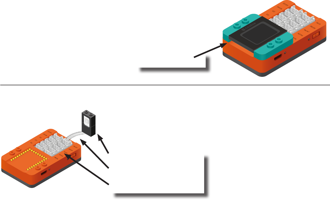
Stacking Modules
Stacking module is done simply by stacking them on the mCenter+
or upon themselves as shown. Ensure pins line up correctly.
Connecting Modules to the Hub
Connecting sensors, trinkets, and other modules to the Hub is done with the Hub
Connector Cable. Connect one side of the cable to the module and the other to
a port on the Hub. As shown.
Stack modules,
ensure gold pins align.
Sensor, Trinket, or other module
Hub Connector Cable
mCenter+’s Hub
42
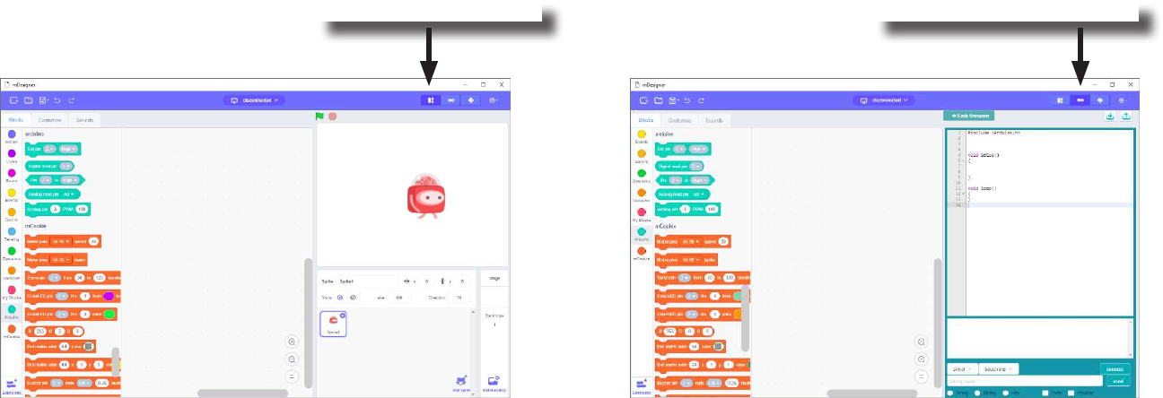
Setup for Scratch
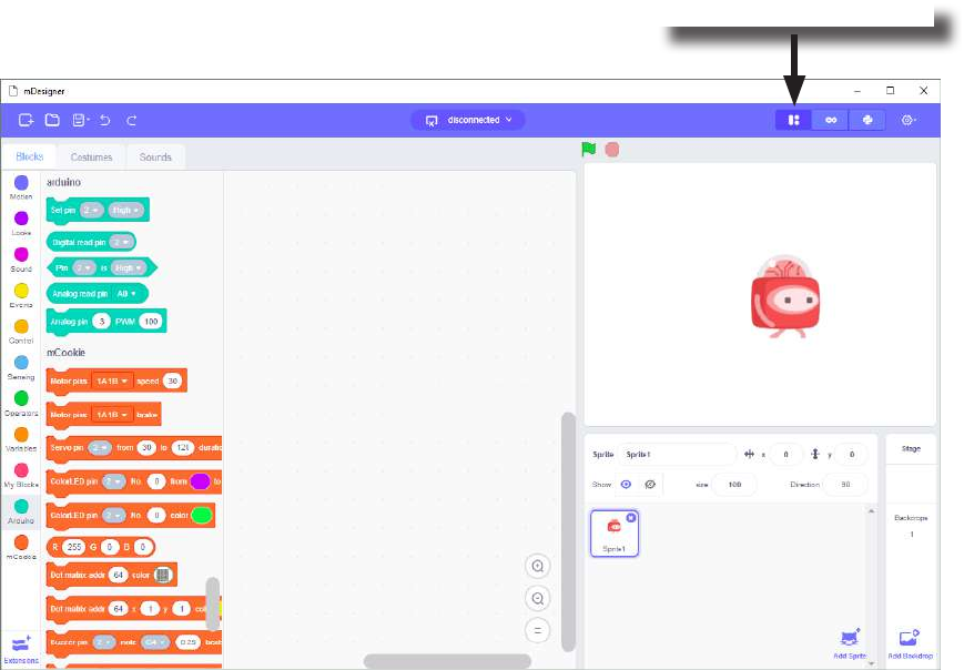
Using the mCookie modules with Scratch can be accomplished in two ways: Live mode and Arduino mode. The projects
in this MIX Kit will use Scratch in Live mode. Arduino mode is an advanced mode and will not be covered in this Kit.
Live Mode Arduino Mode
Select Live Mode here. Select Arduino Mode here.
43
Live Mode
Live Mode is the default mode when using Scratch. It allows you to use Scratch as normal, but with the ability to use mod-
ules included in the MIX Kit. You must upload a special rmware onto the Core module to use this mode.
In this mode, to control the modules, you will need to have your project connected to your computer sending commands in
real time. If you disconnected the project from your computer, your project will no longer be receiving commands.
Select Live Mode here.

44
Live Mode
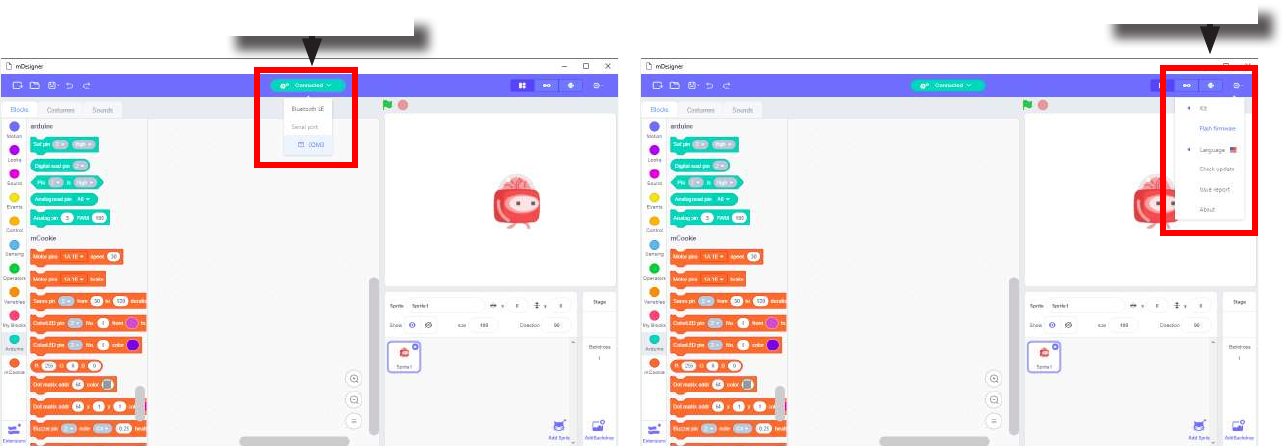
A rmware is a program that runs on the Core module. Live Mode requires a special rmware to be upload onto the Core
module. This special rmware allows the Core module to perform commands sent from your computer in real time.
Uploading this special rmware only needs to be done once, unless it is overwritten with another rmware (such as when
using Arduino mode).
Computer send or receives
commands with mCenter+ over
USB.
mCenter+ acts as a communi-
cation bridge with the Comput-
er and the embedded Core+
module.
Core+ module receives or sends
commands with mCenter+.
45
Live Mode
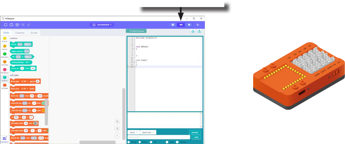
Uploading the Special Firmware
In Hardware
• Ensure drivers are install.
• Connect mCenter+ to your computer using a MicroUSB cable.
• A LED near the power switch should be on. If not, turn on mCenter+ with the power switch.
In Scratch:
• Select the port mCenter+ is connected to.
• Select it again to disconnect. It should show “disconnected” before attempting to upload the rmware.
• Under Settings select Flash rmware and select mCookie to upload the special rmware. Uploading will start.
• Select the port mCenter+ is connected to again to begin using Scratch with MIX hardware.
Select Serial Port. Flash rmware
46
Arduino Mode
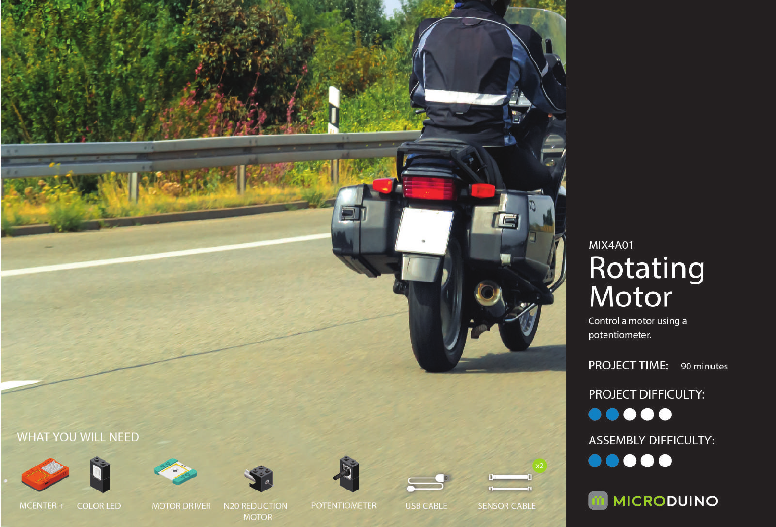
Arduino Mode is a special mode which can be enabled. It acts as a drag and drop editor for programming. The Stage
is disabled and many Block Categories cannot be used.
The main advantage of using Arduino Mode is that code is generated, compiled, and uploaded. This means that you
can disconnect your project from your computer and it can still work. Whereas, during Live Mode, you need to have
your project connected to your computer to instruct your project what to do.
Arduino Mode can be accessed by clicking on the Arduino Mode button.
mCenter+ runs its own program without
needing to be connected to a Computer.
Select Arduino Mode here.
47
Revolutions Indicator
MIX4 - Project 1
(Old Cards: MIX4A-01)

48
About Revolutions Per Minutes (RPM)
Revolutions per minute (abbreviated rpm, RPM, rev/min, r/min) is a measure of the frequency of rotation,
specically the number of rotations around a xed axis in one minute. It is used as a measure of rotation-
al speed of a mechanical component.
Source: https://en.wikipedia.org/wiki/Revolutions_per_minute
49
Review of Modules
mCenter+
Is a ve-in-one module which contains:
• Li-ion Battery: battery pack to power your projects which can be recharged via the USB port.
• mCookie Core+: a tiny central processing unit (CPU), which is the brains of your projects.
• USB Programmer: programs the Core+ module and acts as a serial communication bridge between your
computer and Core+ module.
• Bluetooth Upload: similar to the USB programmer, but works wirelessly over Bluetooth communication.
• Hub: connects various modules such as sensors, trinkets, and other modules to your projects. These mod-
ules can then be accessed by the Core+ module.
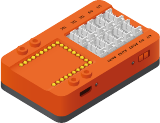
50
Review of Modules
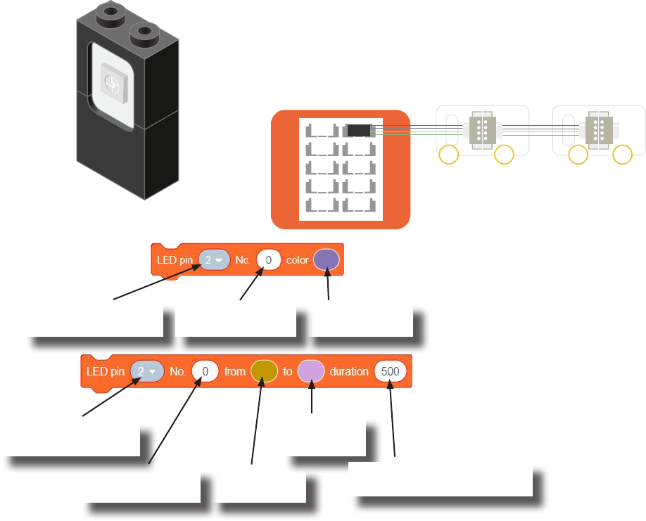
The Color LED is a LED composed of 3 smaller LEDs which emit red, green, and blue.
Each color’s brightness value can be congured individually. This can produce a wide
variety of colors. It is controlled over a special communication protocol which is dier-
ent from the basic “Digital Output” (used by Single-Color LED).
Usage
Color LED
This block congures what color a particular Color LED
displays.
Hub pin the 1st Color
LED is connected.
Transition from
this color.
Transition to
this color.
Color LED - Color Select block
Color LED - Color Transition block
This block causes a particular Color LED to transition from one
color to another color under a time span. (Note: This block must
complete its transition before proceeding to the next block in the
script.)
Index of the Color
LED to congure.
Color to change
the Color LED to.
Hub pin the 1st Color
LED is connected.
Set duration (in milliseconds)
for the transition.
• The Color LED connected
directly to the Hub is index 0.
• The Color LED connected
next in the chain is index 1.
• And so on.
Indexing
2/3
8/9
I2C A2/A3
I2C
I2C
4/5
A6/A7
A0/A1
6/7
IN INOUT OUT
Index of the Color
LED to congure.
ColorLED
Index: 0
ColorLED
Index: 1
51
Review of Modules
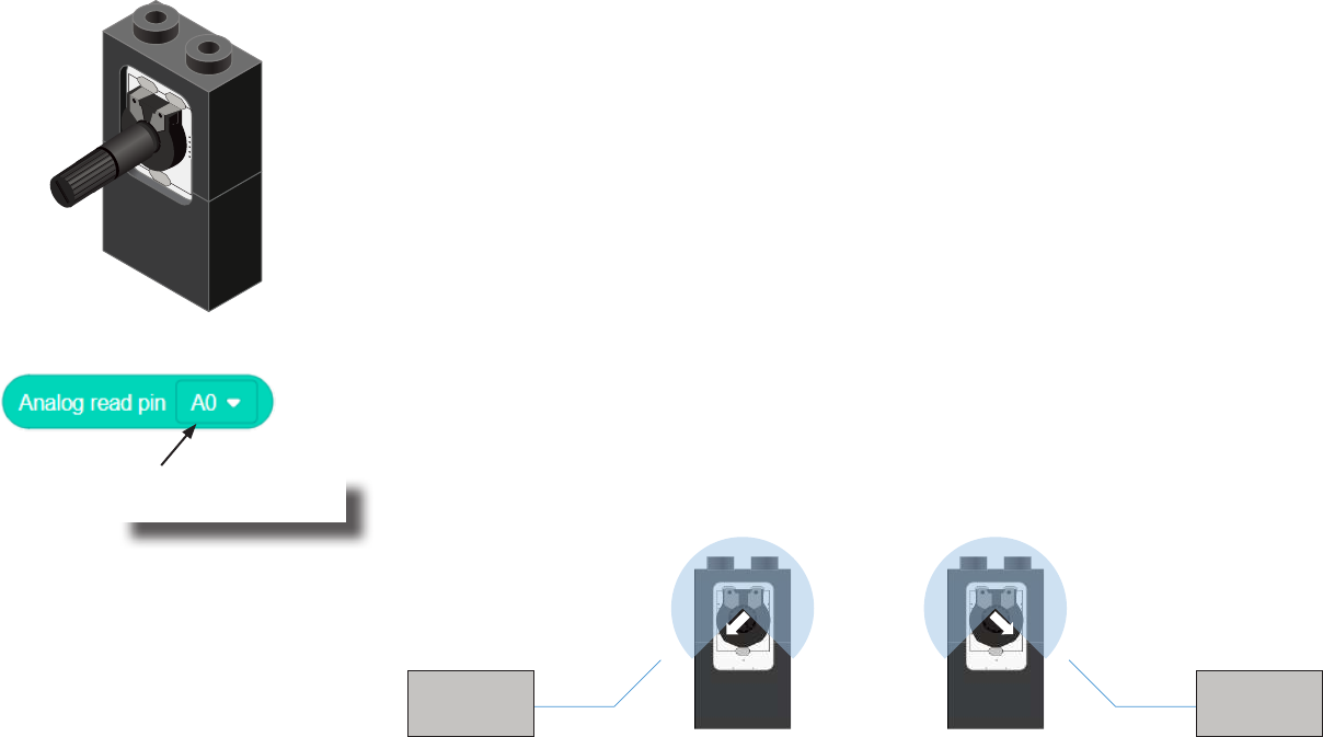
A Potentiometer is a input module which can be turned or rotated right or left. Based
on the position of the knob, it produces a dierent signal value for the Core module to
read. It must be connected to an analog port (ports denoted with “A”).
Analog Read block
This block returns the value from the Potentiometer. A value between 0 and 1023 is returned.
If the potentiometer is turned all the way to the left, it produces a 0 value. If it is turned all
the way tot the right, it produces a 1023 value. In the middle it produces a value around 512.
Potentiometer
Pin the Potentiometer
is connected to.
0 1023
52
Introduction of New Modules
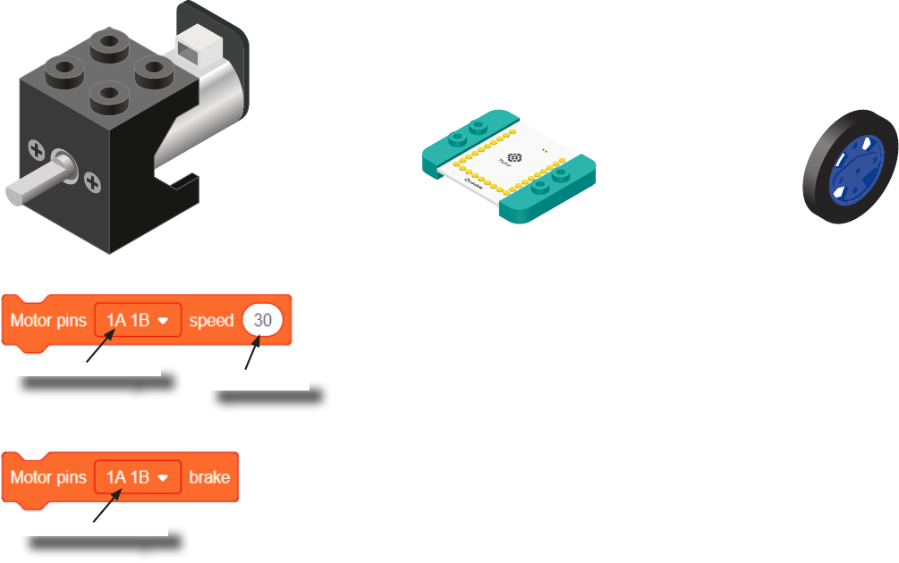
A Motor is a electrical machine which converts electrical energy to mechanical energy. It
is capable of rotating clockwise and counter clockwise. It is controlled by a Motor Con-
troller. A Motor Controller can control up to 2 Motors. A Wheel can be attached to the
Motor.
Motor
Motor Controller Wheel
Motor - Set Speed block
This block sets the speed of the motor. Positive values turns the Motor in one direc-
tion. While negative values turns the Motor in the opposite direction. A value of 0
stops the Motor. Values between -255 and 255 are accepted. 255 is maximum clock-
wise speed. -255 is maximum counter-clockwise speed.
Motor - Brake block
This block sets the speed to 0 to stop the Motor.
Motor to congure.
Motor to congure.
Speed to set.

53
Review of Blocks
Addition Block
This block returns the sum of the left input and right input.
Division Block
This block returns the value of dividing the left input by the right input.
Multiplication Block
This block returns the product of the left input and right input.
Subtraction Block
This block returns the value of subtracting the left input by the right input.
Less Than Block
This block returns TRUE if the left input is less than the right input.
Equal Block
This block returns TRUE if the left input is equal to the right input.
Greater Than Block
This block returns TRUE if the left input is greater than the right input.
54
Review of Concepts
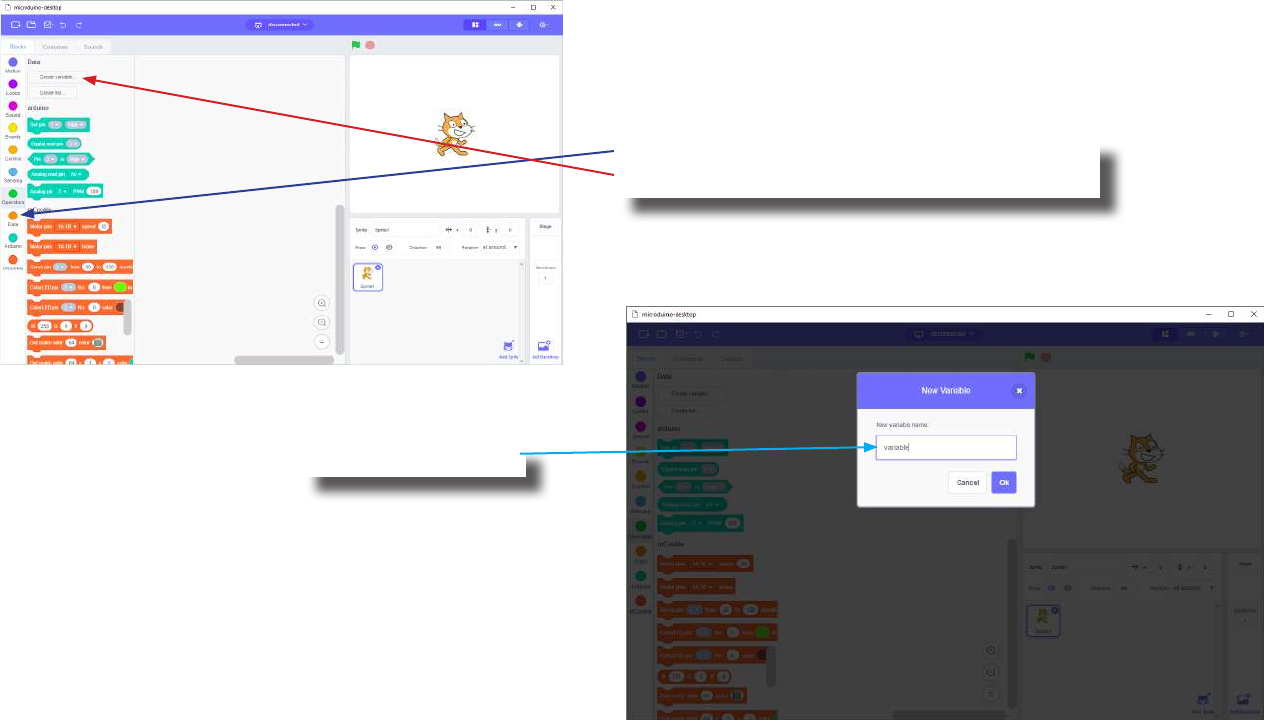
Creating a Variable in Scratch
Click on the “Variable” category.
Then click on the “Create variable...” button.
Name your variable.
55
Review of Concepts
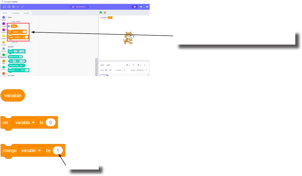
Creating a Variable in Scratch (continued)
Several new blocks will appear which allows
access and modication of the new variable.
Variable Value block
Variable Set block
Variable Change block
This block returns the current value of the variable.
This block sets the value of the variable. It will overwrite the current value.
This block changes the variable value by adding the input value (negative values or blocks are accepted).
input value

56
The Problem
How can we create a motor controller with a revolutions indicator?
57
Project Worksheet
Complete the worksheet below to your best abilities.
1. A solution.
2. List all the parts needed for the solution. What is the purpose of each part?
3. What is a simple explanation of the logic for the solution?
4. Create a ow chart of the solution.
5. How do you assemble and connect the modules for the solution?
6. Congure blocks to relate to the ow chart.
Use a Potentiometer to control the speed of the Motor. Use a Color LED to indicate the revolutions per minute.

58
Project Worksheet - Answers
2. List all the parts needed for the solution. What is the purpose of each part?
1x mCenter+ - control the project, connect sensors and trinkets to project, and supply power.
2x Hub Connector Cable - connect sensors and trinkets to the mCenter+.
1x USB Cable - connect mCenter+ to a computer for charging and programming the project.
1x Motor - motor to control the speed of.
1x Potentiometer - used as an input to control the speed of the motor.
1x Motor Controller - controls and drives the attached motors.
1x Color LED - indicate the revolutions per minute of the motor.
59
Project Worksheet - Answers
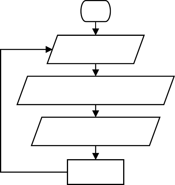
3. What is a simple explanation of the logic for the solution?
Use a Potentiometer as an input to adjust the speed of the Motor.
Use a Color LED to indicate the current revolutions per minute.
Read in the value of the Potentiometer (between 0 and 1023).
Map the Motor’s speed based on the Potentiometer value (accepts values between 0 and 255).
Map the Color LED’s brightness level based on the Potentiometer value (accepts values between 0 and 255).
60
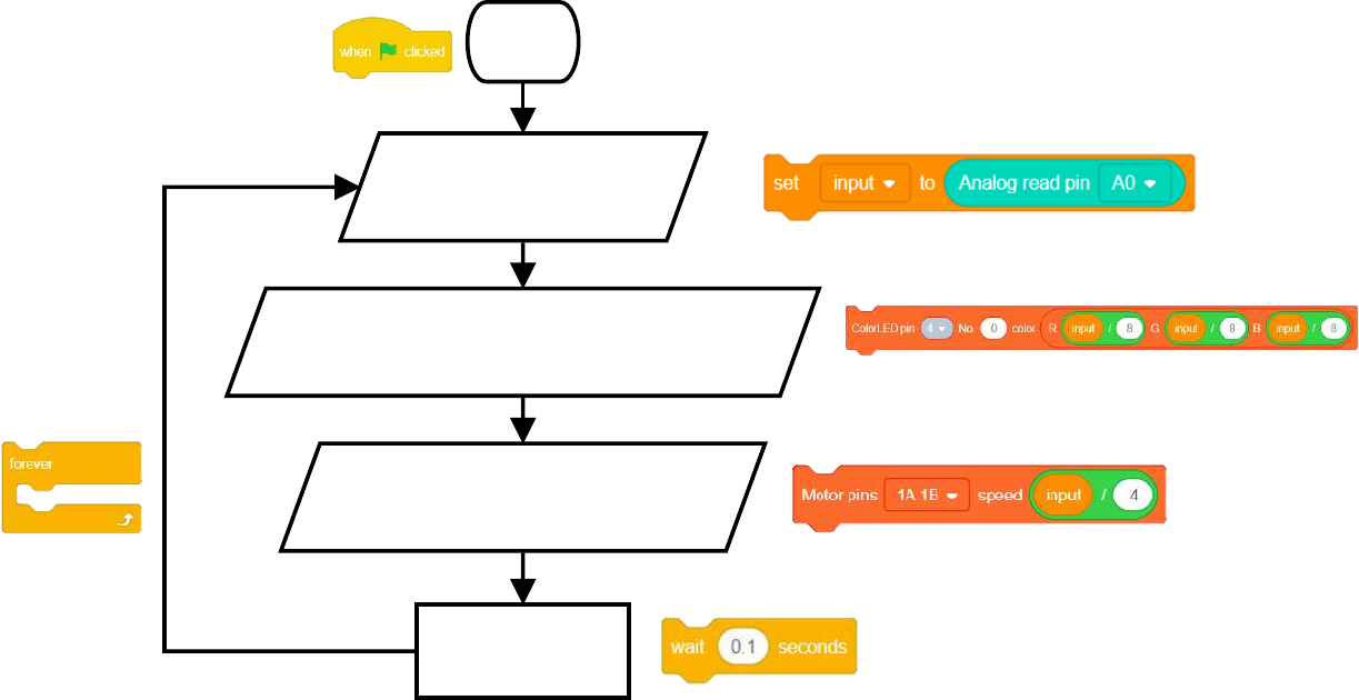
Project Worksheet - Answers
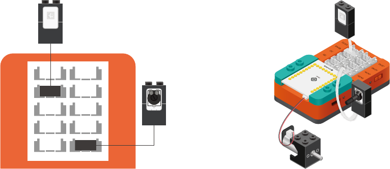
4. Create a ow chart of the solution.
Start
Read and store the
Potentiometer value
Scale the Color LED brightness based
on the Potentiometer value
Scale the Motor speed based
on the Potentiometer value
Short delay
Loop
forever.
61
Project Worksheet - Answers
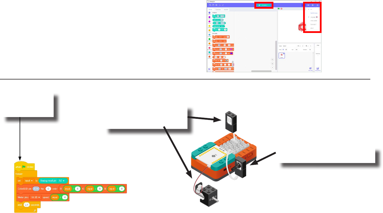
5. How do you assemble and connect the modules for the solution?
1. Stack the Motor Controller onto the mCenter+.
2. Connect a Motor to connector “1A1B” on the Motor Controller.
3. Connect a Color LED (IN port) to pin 4/5.
4. Connect a Potentiometer to pin A0/A1.
5. Insert one end of the USB cable into mCenter+ and connect the other to a computer.
D2/D3
D8/D9
I2C A2/A3
I2C
D4/D5
A6/A7
A0/A1
I2C
D6/D7
62
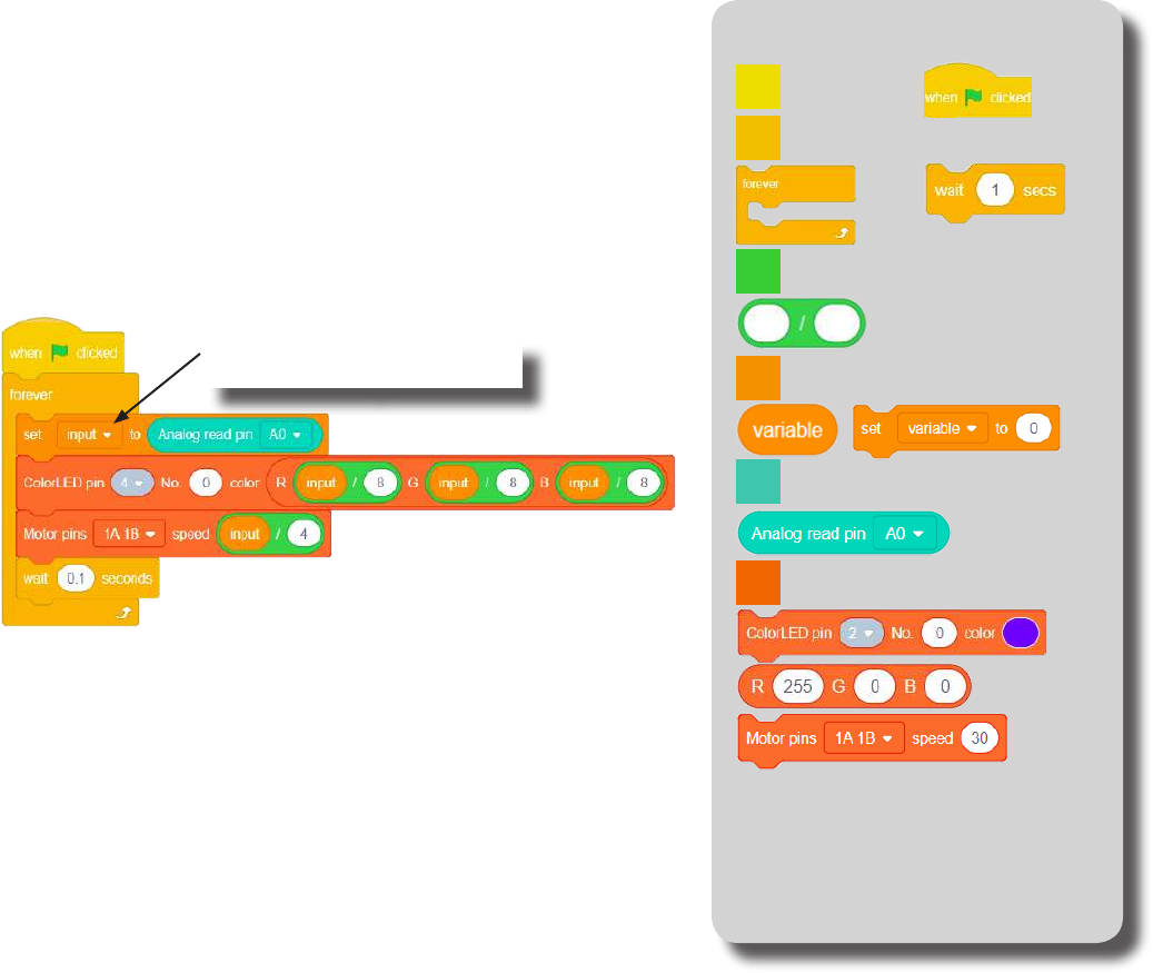
Project Worksheet - Answers
6. Congure blocks to relate to the ow chart.
Start
Read and store the
Potentiometer value
Scale the Color LED brightness based
on the Potentiometer value
Scale the Motor speed based
on the Potentiometer value
Short delay
Loop
forever.
63
The Script
Click Green Flag to activate script. (Create “input” variable rst in
the variable tab.)
Read and store the value
of the Potentiometer (pin A0).
Indicated the RPM with
the Color LED (pin 4).
Set Motor (1) speed based
on Potentiometer value.
Short delay before looping.
Loop.
Control
Events
mCookie
Data
Operators
Arduino
Block Locator
64
Click the green
ag to activate
the script.
1. Rotate the Potentiometer to
adjust the speed of the Motor.
The Motor and Color LED
will react to the position of
the Potentiometer.
Testing the Program
Important:
• Ensure that mCenter+ is on. Flip the switch on mCenter+
to turn it on. An LED on mCenter+ will light up to indicate
power is being supplied.
• Ensure you have selected the Serial Port and ashed the
special rmware (mCookie) rst before testing (this only
needs to be done once unless the rmware is overwritten).
• Ensure you have selected the Serial Port and connected
before testing.
Flash rmware
Select Serial Port
Testing:
65
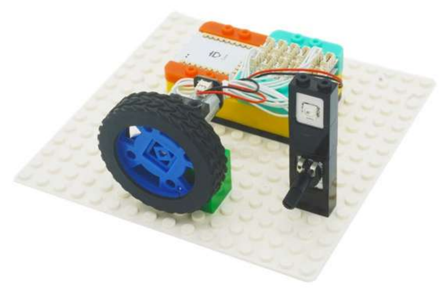
Create a Structure
Create a structure for the project using building blocks, paper, or other crafting materials.
66
Project Challenge
Scale the Potentiometer input so that the values between 0 and 511 causes the
Motor to rotate backwards (-255~0).
Scale the Potentiometer input so that the values between 512 and 1023 causes
the Motor to rotate forwards (0~255).
When the Motor is rotating backwards, make the Color LED red.
When the Motor is rotating forwards, make the Color LED green.

67
Review
Motor Controller - controls and drives attached motors. Can control up to 2 motors.
Motor - converts electrical energy into mechanical energy in the form of torque.
Motor - Set Speed block - set the speed of a motor.
Potentiometer - input module with an adjustable knob.
Analog Read block - reads the value from the potentiometer. Returns a value between 0 and
1023.
Color LED - congurable to display a wide range of colors.
Color LED - Color Select block - congures what color a particular Color LED displays.
68
Expanding the Project
Research
Write down a way of expanding this project. Create it on your own.
Research more about revolutions per minute (RPM).
List 5 contexts where this term is commonly used.
__________________________________________________________
__________________________________________________________
__________________________________________________________
__________________________________________________________
__________________________________________________________
__________________________________________________________
__________________________________________________________
__________________________________________________________
__________________________________________________________
__________________________________________________________
__________________________________________________________
__________________________________________________________
__________________________________________________________
__________________________________________________________
__________________________________________________________
69
Motion Sensor Motor
MIX 4 - Project 2
(Old Cards: MIX4A-02)
70
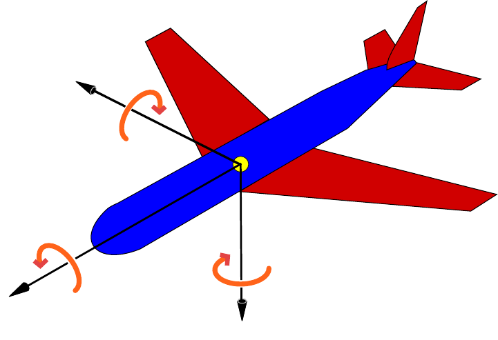
About Roll, Pitch and Yaw
An aircraft in ight is free to rotate in three dimensions: pitch, nose up or down about an axis running from wing to wing;
yaw, nose left or right about an axis running up and down; and roll, rotation about an axis running from nose to tail. The
axes are alternatively designated as lateral, vertical, and longitudinal. These axes move with the vehicle and rotate relative
to the Earth along with the craft. These denitions were analogously applied to spacecraft when the rst manned space-
craft were designed in the late 1950s.
These rotations are produced by torques (or moments) about the principal axes. On an aircraft, these are intentionally
produced by means of moving control surfaces, which vary the distribution of the net aerodynamic force about the vehicle’s
center of mass. Elevators (moving aps on the horizontal tail) produce pitch, a rudder on the vertical tail produces yaw,
and ailerons (aps on the wings that move in opposing directions) produce roll. On a spacecraft, the moments are usually
produced by a reaction control system consisting of small rocket thrusters used to apply asymmetrical thrust on the vehicle.
Source: https://en.wikipedia.org/wiki/Aircraft_principal_axes
Yaw Axis
Roll Axis
Pitch Axis
71
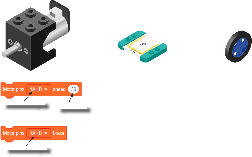
Review of Modules
A Motor is a electrical machine which converts electrical energy to mechanical energy. It
is capable of rotating clockwise and counter clockwise. It is controlled by a Motor Con-
troller. A Motor Controller can control up to 2 Motors. A Wheel can be attached to the
Motor.
Motor
Motor Controller Wheel
Motor - Set Speed block
This block sets the speed of the motor. Positive values turns the Motor in one direc-
tion. While negative values turns the Motor in the opposite direction. A value of 0
stops the Motor. Values between -255 and 255 are accepted. 255 is maximum clock-
wise speed. -255 is maximum counter-clockwise speed.
Motor - Brake block
This block sets the speed to 0 to stop the Motor.
Motor to congure.
Motor to congure.
Speed to set.
72
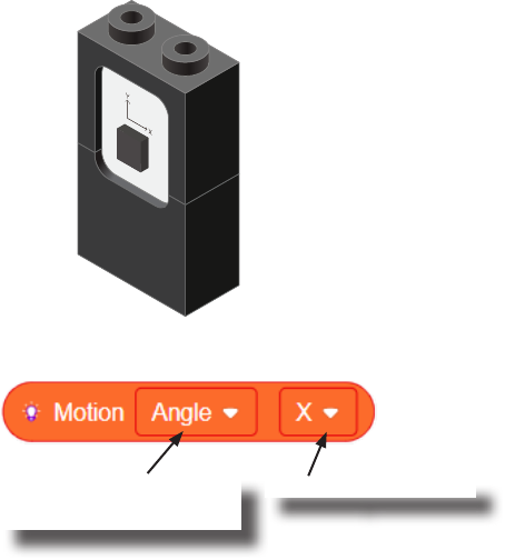
Introduction of New Modules
The Motion module is a triple axis accelerometer and gyroscope.
It is capable of measuring on the X, Y & Z axis the:
• Angle
• Acceleration
• Angular velocity
It uses the “I2C” communication protocol and must be connected to and “I2C” port on
mCenter+.
Motion
Motion - Read block
This block reads data from the Motion module. It is capable of retrieving the angle,
acceleration and angular velocity on the X, Y or Z axis.
Angle, acceleration, or
angular velocity to read.
On the X, Y or Z axis.

73
Review of Blocks
Addition Block
This block returns the sum of the left input and right input.
Division Block
This block returns the value of dividing the left input by the right input.
Multiplication Block
This block returns the product of the left input and right input.
Subtraction Block
This block returns the value of subtracting the left input by the right input.
Less Than Block
This block returns TRUE if the left input is less than the right input.
Equal Block
This block returns TRUE if the left input is equal to the right input.
Greater Than Block
This block returns TRUE if the left input is greater than the right input.
74
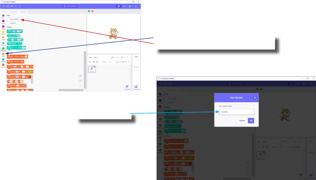
Review of Concepts
Creating a Variable in Scratch
Click on the “Variable” category.
Then click on the “Create variable...” button.
Name your variable.
75
Review of Concepts
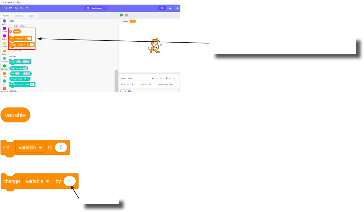
Creating a Variable in Scratch (continued)
Several new blocks will appear which allows
access and modication of the new variable.
Variable Value block
Variable Set block
Variable Change block
This block returns the current value of the variable.
This block sets the value of the variable. It will overwrite the current value.
This block changes the variable value by adding the input value (negative values or blocks are accepted).
input value

76
The Problem
How can we control a motor using a motion module?
77
Project Worksheet
Complete the worksheet below to your best abilities.
1. A solution.
2. List all the parts needed for the solution. What is the purpose of each part?
3. What is a simple explanation of the logic for the solution?
4. Create a ow chart of the solution.
5. How do you assemble and connect the modules for the solution?
6. Congure blocks to relate to the ow chart.
Use a Motion module to detect the pitch angle. Change the speed and direction of the Motor based on the pitch
angle.

78
Project Worksheet - Answers
2. List all the parts needed for the solution. What is the purpose of each part?
1x mCenter+ - control the project, connect sensors and trinkets to project, and supply power.
1x Hub Connector Cable - connect sensors and trinkets to the mCenter+.
1x USB Cable - connect mCenter+ to a computer for charging and programming the project.
1x Motor - motor to control the speed of.
1x Motion - detect motion.
1x Motor Controller - controls and drives the attached motors.
79
Project Worksheet - Answers
3. What is a simple explanation of the logic for the solution?
Use a Motion module to detect the pitch.
Read and store the “X” angle (pitch).
Constrain the value between -90 and 90.
Multiple the value by 2.8 and use that to set the speed of the motor:
• -90 * 2.8 = -252
• 90 * 2.8 = 252
Produces a value between -252 and 252 for speed of the motor.
80
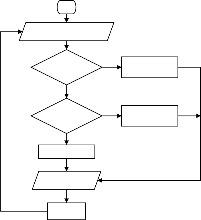
Project Worksheet - Answers
4. Create a ow chart of the solution.
Start
Read and store the raw pitch value
from the Motion module
Is the raw pitch
value < -90?
Is the raw pitch
value > 90?
Constrain the value
to -90 and store it
Constrain the value
to 90 and store it
Store the raw value
Set Motor speed based
on constrained value
Short delay
Loop
forever.
True
True
False
False
81
Project Worksheet - Answers
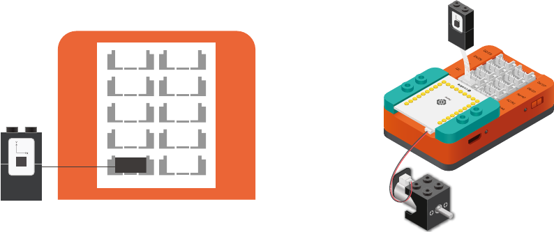
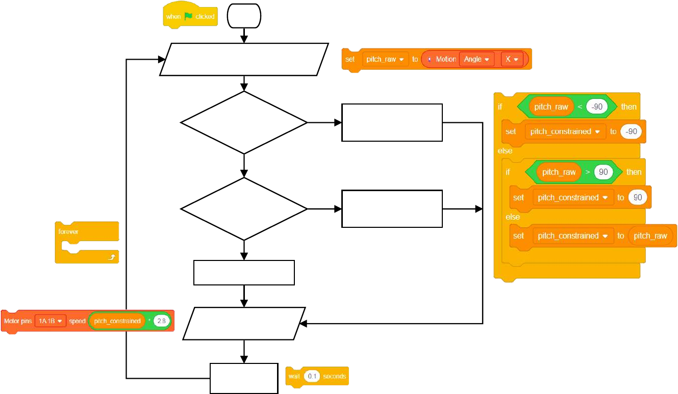
5. How do you assemble and connect the modules for the solution?
1. Stack the Motor Controller onto the mCenter+.
2. Connect a Motor to connector “1A1B” on the Motor Controller.
3. Connect the Motion module to a “I2C” pin.
4. Insert one end of the USB cable into mCenter+ and connect the other to a computer.
D2/D3
D8/D9
I2C A2/A3
I2C
D4/D5
A6/A7
A0/A1
I2C
D6/D7
82
Project Worksheet - Answers
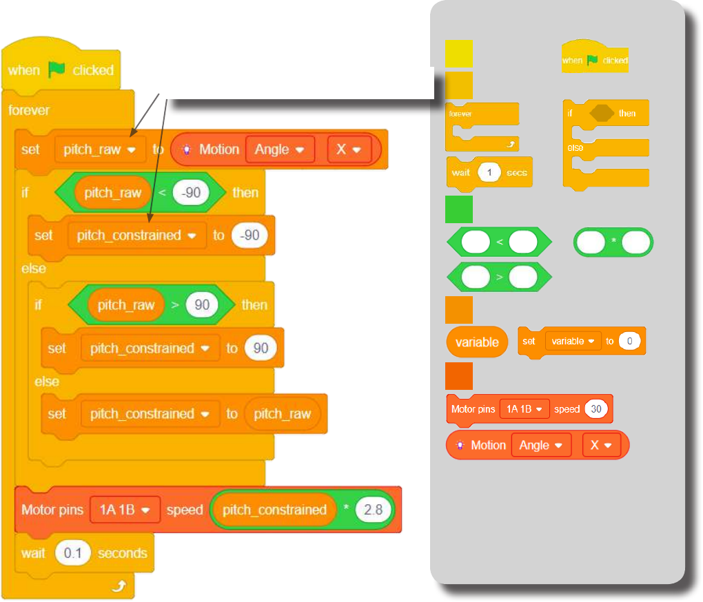
6. Congure blocks to relate to the ow chart.
Start
Read and store the raw pitch value
from the Motion module
Is the raw pitch
value < -90?
Is the raw pitch
value > 90?
Constrain the value
to -90 and store it
Constrain the value
to 90 and store it
Store the raw value
Set Motor speed based
on constrained value
Short delay
Loop
forever.
True
True
False
False
83
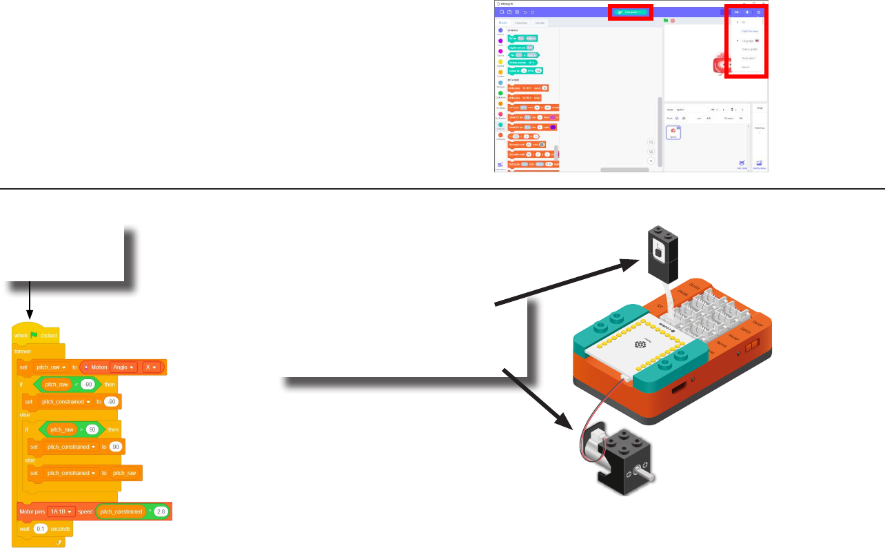
The Script Block Locator
Control
Events
mCookie
Data
Operators
Click Green Flag to activate script.
(Create “pitch_raw” and “pitch_constrained”
variables rst in the variable tab.)
Read and store the “X” angle
from the Motion module.
Check if the pitch (raw) value is < -90.
Constrain it to -90.
Check if the pitch (raw) value is > 90.
Constrain it to 90.
If between -90 and 90.
Then accept the raw value.
Set the Motor (1) speed based
on the constrained “X” angle value.
Short delay before looping.
Loop.
84
Click the green
ag to activate
the script.
1. Rotate the Motion module
along the “X” axis (pitch).
2. The Motor will turn accordingly.
Testing the Program
Important:
• Ensure that mCenter+ is on. Flip the switch on mCenter+
to turn it on. An LED on mCenter+ will light up to indicate
power is being supplied.
• Ensure you have selected the Serial Port and ashed the
special rmware (mCookie) rst before testing (this only
needs to be done once unless the rmware is overwritten).
• Ensure you have selected the Serial Port and connected
before testing.
Flash rmware
Select Serial Port
Testing:
85
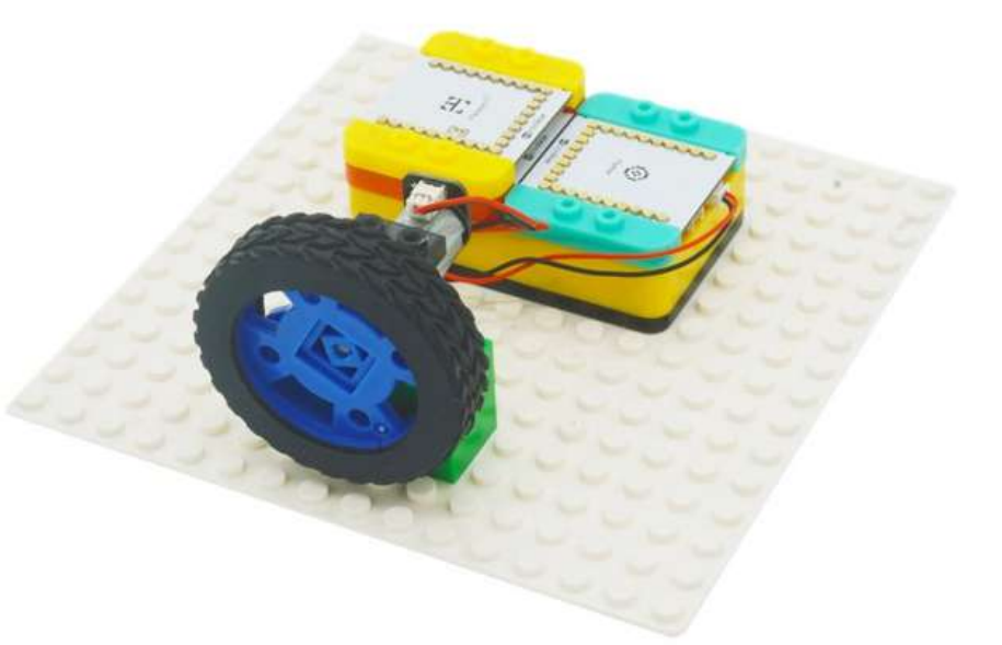
Create a Structure
Create a structure for the project using building blocks, paper, or other crafting materials.
86
Project Challenge
Constrain the “X” angle to -20 and 20.
How does the motor react to this new constrained angle?
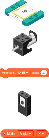
87
Review
Motor Controller - controls and drives attached motors. Can control up to 2 motors.
Motor - converts electrical energy into mechanical energy in the form of torque.
Motor - Set Speed block - set the speed of a motor.
Motion - module which detects motion such as roll, paw and yaw.
Motion - Read block - returns various motion readings from the Motion module.
88
Expanding the Project
Research
Write down a way of expanding this project. Create it on your own.
Research more about roll, pitch and yaw.
Why is this information important to aircrafts?
__________________________________________________________
__________________________________________________________
__________________________________________________________
__________________________________________________________
__________________________________________________________
__________________________________________________________
__________________________________________________________
__________________________________________________________
__________________________________________________________
__________________________________________________________
__________________________________________________________
__________________________________________________________
__________________________________________________________
__________________________________________________________
__________________________________________________________

89
Motion Sensitive Emoticon
MIX 4 - Project 3
(Old Cards: MIX4A-03)

90
About Vision Stabilization
The vestibulo-ocular reex (VOR) is a reex, where activation of the vestibular system causes eye movement. This reex
functions to stabilize images on the retinas during head movement by producing eye movements in the direction opposite
to head movement, thus preserving the image on the center of the visual eld(s).
For example, when the head moves to the right, the eyes move to the left, and vice versa. Since slight head movement is
present all the time, the VOR is very important for stabilizing vision: patients whose VOR is impaired nd it dicult to read
using print, because they cannot stabilize the eyes during small head tremors, and also because damage to the VOR can
cause vestibular nystagmus.
Source: https://en.wikipedia.org/wiki/Vestibulo%E2%80%93ocular_reex
91
Review of Modules
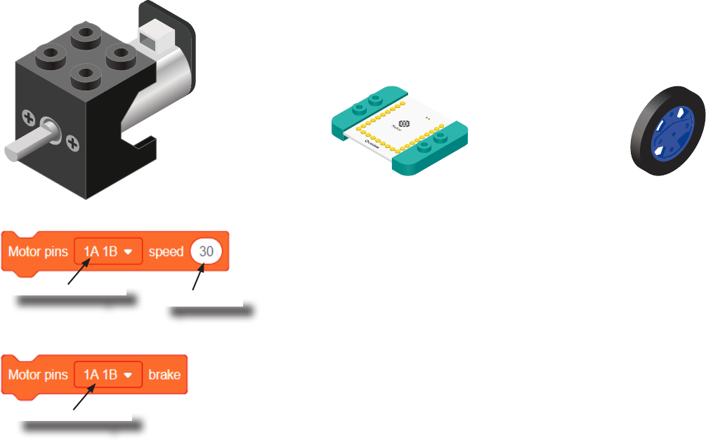
A Motor is a electrical machine which converts electrical energy to mechanical energy. It
is capable of rotating clockwise and counter clockwise. It is controlled by a Motor Con-
troller. A Motor Controller can control up to 2 Motors. A Wheel can be attached to the
Motor.
Motor
Motor Controller Wheel
Motor - Set Speed block
This block sets the speed of the motor. Positive values turns the Motor in one direc-
tion. While negative values turns the Motor in the opposite direction. A value of 0
stops the Motor. Values between -255 and 255 are accepted. 255 is maximum clock-
wise speed. -255 is maximum counter-clockwise speed.
Motor - Brake block
This block sets the speed to 0 to stop the Motor.
Motor to congure.
Motor to congure.
Speed to set.
92
Review of Modules
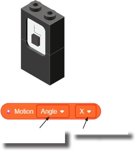
The Motion sensor is a triple axis accelerometer and gyroscope.
It is capable of measuring on the X, Y & Z axis the:
• Angle
• Acceleration
• Angular velocity
It uses the “I2C” communication protocol and must be connected to and “I2C” port on
mCenter+.
Motion
Motion - Read block
This block reads data from the Motion module. It is capable of retrieving the angle,
acceleration and angular velocity on the X, Y or Z axis.
Angle, acceleration, or
angular velocity to read.
On the X, Y or Z axis.

93
Review of Blocks
Addition Block
This block returns the sum of the left input and right input.
Division Block
This block returns the value of dividing the left input by the right input.
Multiplication Block
This block returns the product of the left input and right input.
Subtraction Block
This block returns the value of subtracting the left input by the right input.
Less Than Block
This block returns TRUE if the left input is less than the right input.
Equal Block
This block returns TRUE if the left input is equal to the right input.
Greater Than Block
This block returns TRUE if the left input is greater than the right input.
94
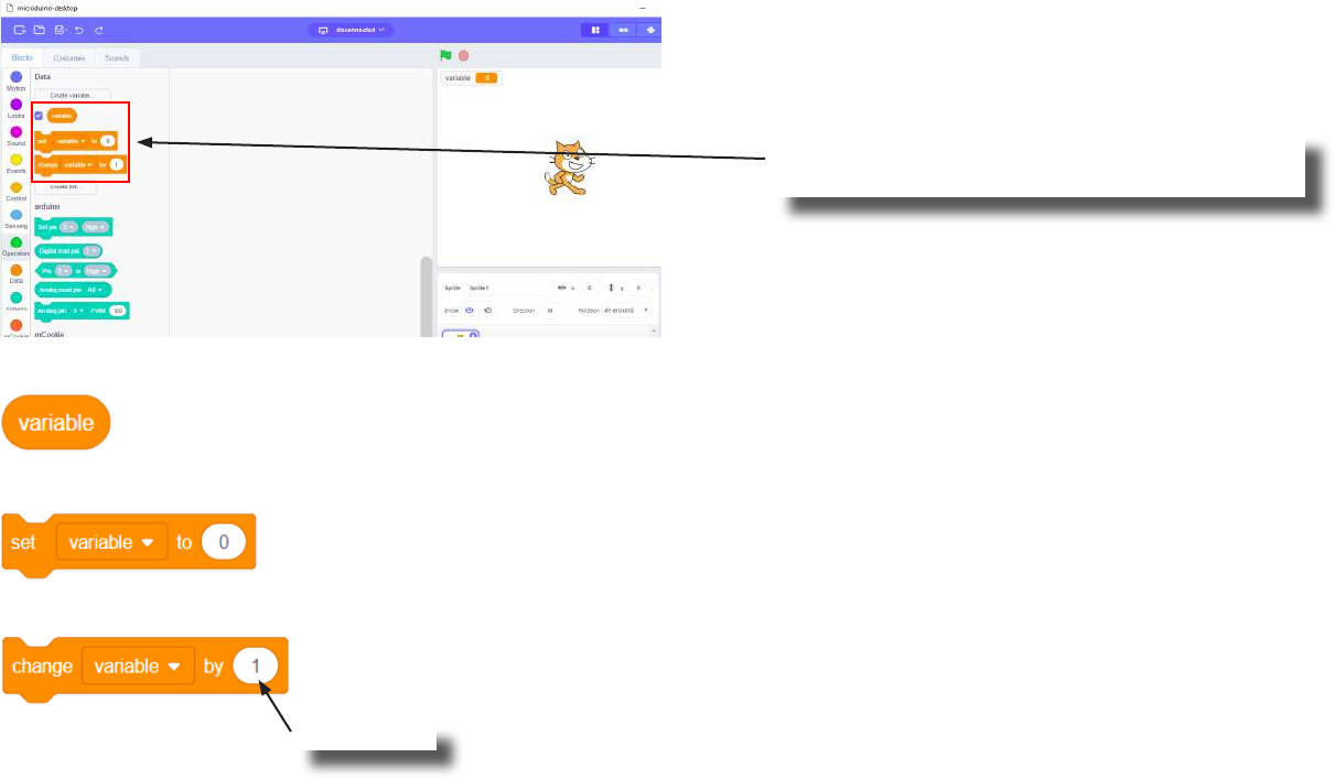
Review of Concepts
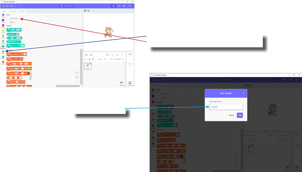
Creating a Variable in Scratch
Click on the “Variable” category.
Then click on the “Create variable...” button.
Name your variable.
95
Review of Concepts
Creating a Variable in Scratch (continued)
Several new blocks will appear which allows
access and modication of the new variable.
Variable Value block
Variable Set block
Variable Change block
This block returns the current value of the variable.
This block sets the value of the variable. It will overwrite the current value.
This block changes the variable value by adding the input value (negative values or blocks are accepted).
input value

96
The Problem
How can we create a motion sensitive Emoticon robot?
97
Project Worksheet
Complete the worksheet below to your best abilities.
1. A solution.
2. List all the parts needed for the solution. What is the purpose of each part?
3. What is a simple explanation of the logic for the solution?
4. Create a ow chart of the solution.
5. How do you assemble and connect the modules for the solution?
6. Congure blocks to relate to the ow chart.
Use the Motion module to detect the “X” angle (pitch). Set the eyes (2 Motors) spin speed based on the pitch
value.

98
Project Worksheet - Answers
2. List all the parts needed for the solution. What is the purpose of each part?
1x mCenter+ - control the project, connect sensors and trinkets to project, and supply power.
1x Hub Connector Cable - connect sensors and trinkets to the mCenter+.
1x USB Cable - connect mCenter+ to a computer for charging and programming the project.
2x Motor - motor to simulate the robot’s eyes.
1x Motion - detect motion.
1x Motor Controller - controls and drives the attached motors.
2x Wheel - attach to motor.
99
Project Worksheet - Answers
3. What is a simple explanation of the logic for the solution?
Use a Motion module to detect the pitch.
Use 2 Motors (with Wheels) to simulate the robot’s eyes.
Read and store the “X” angle (pitch).
Constrain the value between -20 and 20.
Multiple the value by 5 and use that to set the speed of the motors:
• -20 * 5 = -100
• 20 * 5 = 100
Produces a value between -100 and 100 for speed of the motors.
100
Project Worksheet - Answers
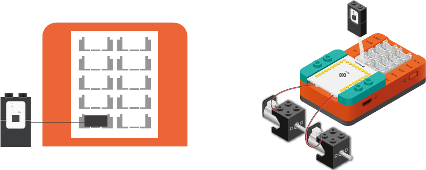
4. Create a ow chart of the solution.
Start
Read and store the raw pitch value
from the Motion module
Is the raw pitch
value < -20?
Is the raw pitch
value > 20?
Constrain the value
to -20 and store it
Constrain the value
to 20 and store it
Store the raw value
Set Motors speed based
on constrained value
Short delay
Loop
forever.
True
True
False
False
101
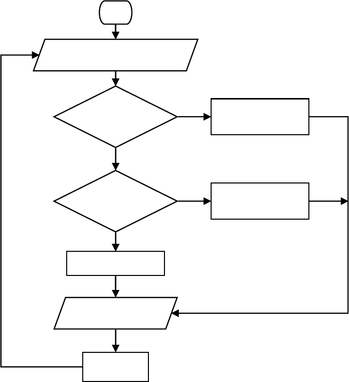
Project Worksheet - Answers
5. How do you assemble and connect the modules for the solution?
1. Stack the Motor Controller onto mCenter+.
2. Connect a Motor to connector “1A1B” on the Motor Controller.
3. Connect a Motor to connector “2A2B” on the Motor Controller.
4. Connect the Motion module to a “I2C” pin.
5. Insert one end of the USB cable into mCenter+ and connect the other to a computer.
D2/D3
D8/D9
I2C A2/A3
I2C
D4/D5
A6/A7
A0/A1
I2C
D6/D7
102
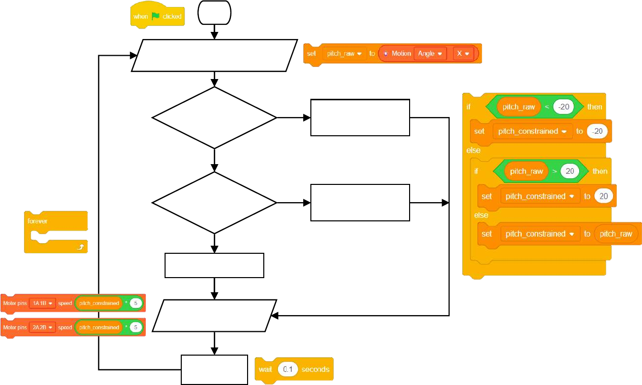
Project Worksheet - Answers
6. Congure blocks to relate to the ow chart.
Start
Read and store the raw pitch value
from the Motion module
Is the raw pitch
value < -20?
Is the raw pitch
value > 20?
Constrain the value
to -20 and store it
Constrain the value
to 20 and store it
Store the raw value
Set Motors speed based
on constrained value
Short delay
Loop
forever.
True
True
False
False
103
The Script Block Locator
Control
Events
mCookie
Data
Operators
Click Green Flag to activate script.
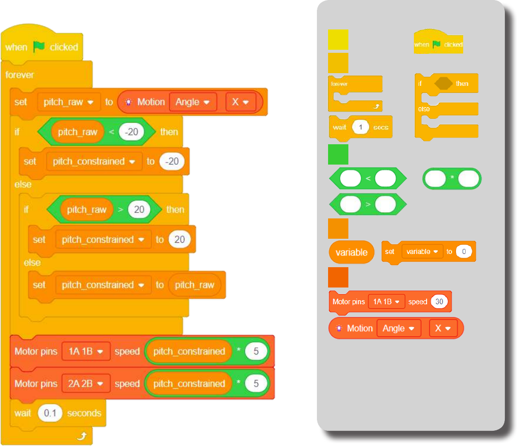
Read and store the “X” angle
from the Motion module.
Check if the pitch (raw) value is < -20.
Constrain it to -20.
Check if the pitch (raw) value is > 20.
Constrain it to 20.
If between -20 and 20.
Then accept the raw value.
Set the Motor (1) speed based
on the constrained “X” angle value.
Short delay before looping.
Loop.
Set the Motor (2) speed based
on the constrained “X” angle value.
104
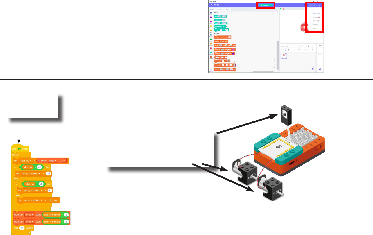
Click the green
ag to activate
the script.
1. Rotate the Motion module along
the “X” axis (pitch).
2. The Motors will turn accordingly.
Testing the Program
Important:
• Ensure that mCenter+ is on. Flip the switch on mCenter+
to turn it on. An LED on mCenter+ will light up to indicate
power is being supplied.
• Ensure you have selected the Serial Port and ashed the
special rmware (mCookie) rst before testing (this only
needs to be done once unless the rmware is overwritten).
• Ensure you have selected the Serial Port and connected
before testing.
Flash rmware
Select Serial Port
Testing:
105
Create a Structure
Create a structure for the project using building blocks, paper, or other crafting materials.
106
Project Challenge
Increase the maximum speed in which the Motors can spin.
Hint: Change the multiplication factor when setting the Motor speeds.
Change the way the motors react to the pitch value to your liking.
(Example, eyes rotating in opposing directions.)

107
Review
Motor Controller - controls and drives attached motors. Can control up to 2 motors.
Motor - converts electrical energy into mechanical energy in the form of torque.
Motor - Set Speed block - set the speed of a motor.
Motion - module which detects motion such as roll, paw and yaw.
Motion - Read block - returns various motion readings from the Motion module.
Wheel - attaches to the Motor.
108
Expanding the Project
Research
Write down a way of expanding this project. Create it on your own.
Research other eye reexes such as the “Optokinetic response”.
Why are these reexes important and why do they happen without your direct control?
__________________________________________________________
__________________________________________________________
__________________________________________________________
__________________________________________________________
__________________________________________________________
__________________________________________________________
__________________________________________________________
__________________________________________________________
__________________________________________________________
__________________________________________________________
__________________________________________________________
__________________________________________________________
__________________________________________________________
__________________________________________________________
__________________________________________________________

109
Single-axis Camera Stabilizer
MIX 4 - Project 4
(Old Cards: MIX4A-04)

110
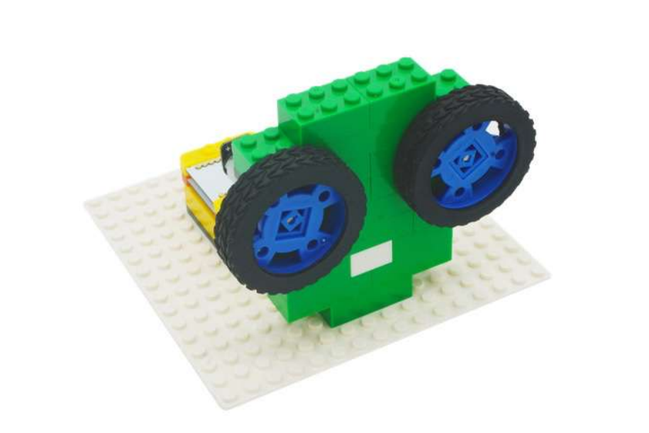
A camera stabilizer, or camera–stabilizing mount, is a device designed to hold a camera in a manner that prevents or com-
pensates for unwanted camera movement, such as “camera shake”.
For small hand-held cameras, a harness or contoured frame steadies the camera against the photographer’s body. In some
models, the camera mount is on an arm that protrudes in front of the photographer; beneath the camera is a handle grip.
Another variation positions the camera atop a fulcrum braced against the photographer’s chest or abdomen.
Source: https://en.wikipedia.org/wiki/Camera_stabilizer
About Camera Stabilizers
111
Review of Modules
A Servo is an actuator which consist of a motor and other electronic components which
allows for precise angle adjustments of the attached horn. The servo included in the kit
has an adjustable angle range between 0 and 180 degrees.
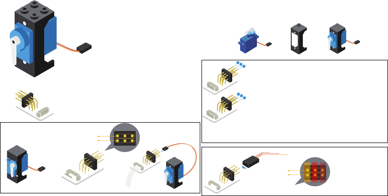
Assembly
Install the Servo into the Servo Block
Connector and fasten with the included
screws.
Servo
+ =
Connectivity
A Servo Connector is required in order to
connect the Servo to the Hub. The Servo
Connector can support up 2 Servos at a time.
First Servo
Second Servo
+=
Servo Servo Connector
31 2
64 5
1
2
3
The top pins correspond to the odd pin on the Connector.
The bottom pins correspond to the even pin on the
Connector.
For example, if the Servo Connector is connected to pin 6/7 on the Hub. The
Servo connected to the top pins would be referenced as pin 7. The Servo con-
nected to the bottom pins would be referenced as pin 6.
Hub Connector Cable
(to Hub)
GND 1/2
VCC IMPORTANT: Ensure
the Servo’s connector
is in the correct orien-
tation. As having the
connector ipped can
damage the servo or
other components.
31 2
64 5
First Servo
Second Servo
GND
(Brown)
VCC
(Red)
Signal Pin
(Orange)
4
5
6
112
Review of Modules
Servo (continued)
Usage
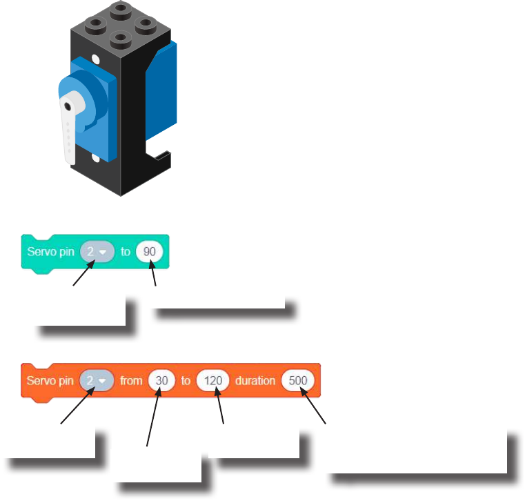
Servo - Set Angle block
The angle, between 0 and 180 degrees, is adjustable using blocks in Scratch.
Calibrating your attachment (the horn) to your desired 0 angle can be done by rst set-
ting the servo to 0 degrees, then attaching the horn as desired.
Servo - Move From-To Angle block
Sets the horn angle of the Servo. Quickly moves (as fast as possible) to the desired angle.
Sets the horn angle from the starting angle to the target angle. This
movement is performed in the specied duration time.
Pin the Servo is
connected to.
Angle to set Servo to.
Pin the Servo is
connected to. Starting angle
of Servo.
Target angle
for Servo.
Time in millisecond to move
from starting angle to target
angle.
113
Review of Modules
The Motion sensor is a triple axis accelerometer and gyroscope.
It is capable of measuring on the X, Y & Z axis the:
• Angle
• Acceleration
• Angular velocity
It uses the “I2C” communication protocol and must be connected to and “I2C” port on
mCenter+.
Motion
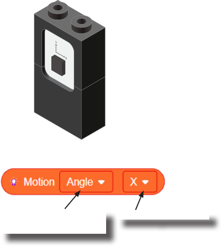
Motion - Read block
This block reads data from the Motion module. It is capable of retrieving the angle,
acceleration and angular velocity on the X, Y or Z axis.
Angle, acceleration, or
angular velocity to read.
On the X, Y or Z axis.

114
Review of Blocks
Addition Block
This block returns the sum of the left input and right input.
Division Block
This block returns the value of dividing the left input by the right input.
Multiplication Block
This block returns the product of the left input and right input.
Subtraction Block
This block returns the value of subtracting the left input by the right input.
Less Than Block
This block returns TRUE if the left input is less than the right input.
Equal Block
This block returns TRUE if the left input is equal to the right input.
Greater Than Block
This block returns TRUE if the left input is greater than the right input.

115
The Problem
How can we create a one-axis camera stabilizer?
116
Project Worksheet
Complete the worksheet below to your best abilities.
1. A solution.
2. List all the parts needed for the solution. What is the purpose of each part?
3. What is a simple explanation of the logic for the solution?
4. Create a ow chart of the solution.
5. How do you assemble and connect the modules for the solution?
6. Congure blocks to relate to the ow chart.
Use the Motion module to detect the current “Y” angle. Stabilize the project using a Servo compensating for the
“Y” angle value.

117
Project Worksheet - Answers
2. List all the parts needed for the solution. What is the purpose of each part?
1x mCenter+ - control the project, connect sensors and trinkets to project, and supply power.
2x Hub Connector Cable - connect sensors and trinkets to the mCenter+.
1x USB Cable - connect mCenter+ to a computer for charging and programming the project.
1x Servo - to steady the camera.
1x Servo Connector - connect a Servo to mCenter+.
1x Motion - detect the un-stabilized angle.

118
Project Worksheet - Answers
3. What is a simple explanation of the logic for the solution?
Use a Motion module to detect the “Y” angle. The Motion module must lay horizontal.
Use a Servo to compensate for the “Y” angle for stabilization.
Read “Y” angle.
Set the Servo to compensate for the “Y” angle by adding 90.
Display the angle the Servo is set to.
119
Project Worksheet - Answers
4. Create a ow chart of the solution.
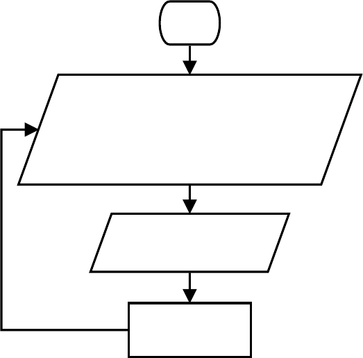
Start
Read the "Y" angle
from the Motion module
Set the Servo angle to compensate
for the "Y" angle.
Display the angle
the Servo was set to
Short delay
Loop
forever.
120
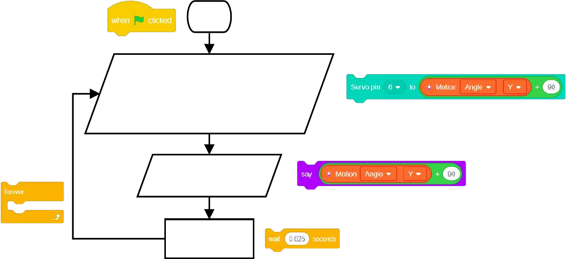
Project Worksheet - Answers
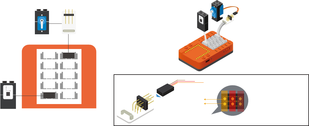
5. How do you assemble and connect the modules for the solution?
1. Connect a Servo Connector to pin 6/7 using a Hub Connector Cable.
2. Connect two Servos to the Servo Connector. Ensure the connector is in the correct orientation.
3. Connect the Motion module to a “I2C” pin.
4. Insert one end of the USB cable into mCenter+ and connect the other to a computer.
GND 1/2
VCC IMPORTANT: Ensure
the Servo’s connector
is in the correct orien-
tation. As having the
connector ipped can
damage the servo or
other components.
31 2
64 5
First Servo
Second Servo
GND
(Brown)
VCC
(Red)
Signal Pin
(Orange)
D2/D3
D8/D9
I2C A2/A3
I2C
D4/D5
A6/A7
A0/A1
I2C
D6/D7
121
Project Worksheet - Answers
6. Congure blocks to relate to the ow chart.
Start
Read the "Y" angle
from the Motion module
Set the Servo angle to compensate
for the "Y" angle.
Display the angle
the Servo was set to
Short delay
Loop
forever.
122
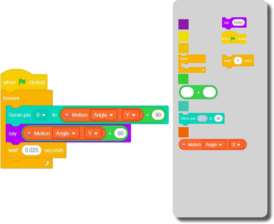
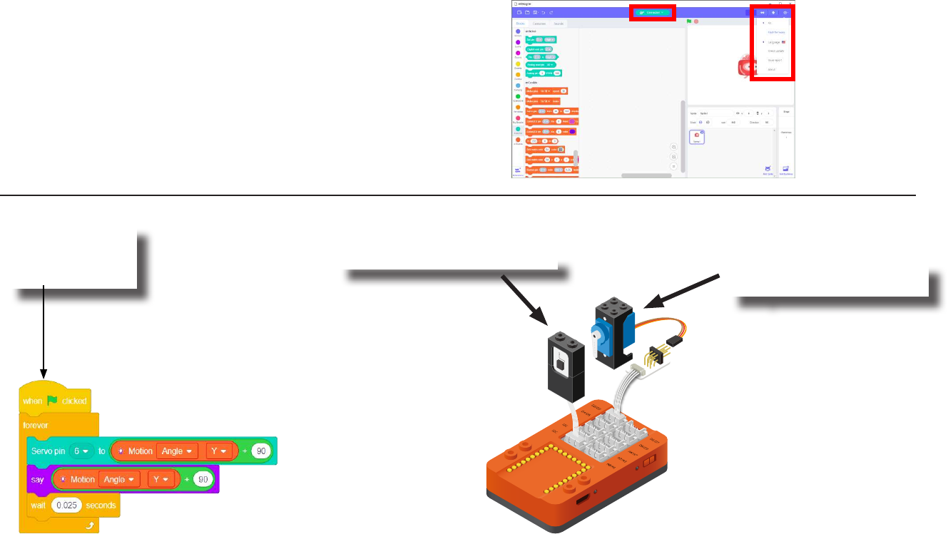
The Script Block Locator
Click Green Flag to activate script.
Short delay before looping.
Loop.
Read “Y” angle and
compensate with Servo (pin 6).
Display the Servo angle on the stage.
Control
Events
mCookie
Operators
Arduino
Looks
*** Enable this block under settings (gear icon on
top right). Then select Kit > mCookie Extension.
***
123
Click the green
ag to activate
the script. 1. Rotate the Motion module. 2. The Servo will rotate to
compensate.
Testing the Program
Important:
• Ensure that mCenter+ is on. Flip the switch on mCenter+
to turn it on. An LED on mCenter+ will light up to indicate
power is being supplied.
• Ensure you have selected the Serial Port and ashed the
special rmware (mCookie) rst before testing (this only
needs to be done once unless the rmware is overwritten).
• Ensure you have selected the Serial Port and connected
before testing.
Flash rmware
Select Serial Port
Testing:
Note: If the program is working correctly and you wish to use the program without being connected to your computer. Switch to Arduino mode
(top right), then “Flash Program” (this overrides the special rmware, you will need to reash to use Live mode).
124
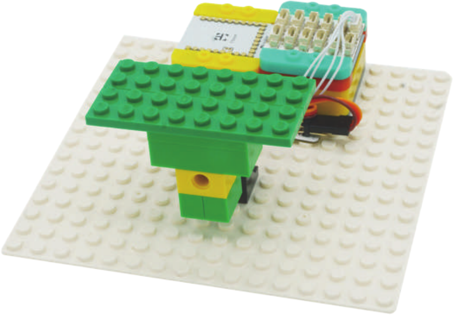
Create a Structure
Create a structure for the project using building blocks, paper, or other crafting materials.
125
Project Challenge
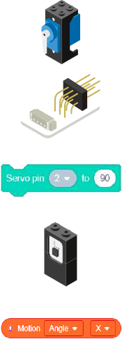
Add a Color LED to the project.
Use it to indicate when the camera stabilizer is at an extreme angle.
126
Review
Servo - an actuator with precise angle control.
Servo Connector - an adapter to connect a Servo to the Hub on mCenter+.
Servo - Set Angle block - Sets the angle of the Servo. Quickly moves (as fast as possible) to the
desired angle.
Motion - module which detects motion such as roll, paw and yaw.
Motion - Read block - returns various motion readings from the Motion module.
127
Expanding the Project
Research
Write down a way of expanding this project. Create it on your own.
Research other things self-stabilize.
What are some very important life saving applications of this principle?
__________________________________________________________
__________________________________________________________
__________________________________________________________
__________________________________________________________
__________________________________________________________
__________________________________________________________
__________________________________________________________
__________________________________________________________
__________________________________________________________
__________________________________________________________
__________________________________________________________
__________________________________________________________
__________________________________________________________
__________________________________________________________
__________________________________________________________
128
Air Bag
MIX 4 - Project 5
(Old Cards: MIX4A-06)

129
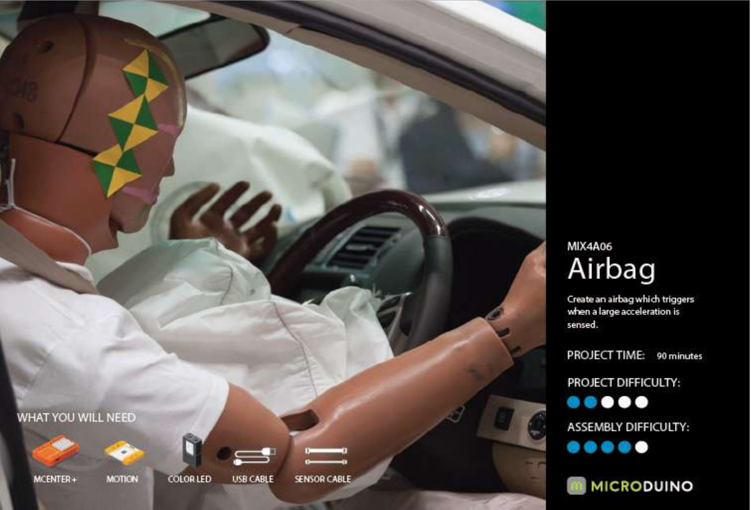
An airbag is a type of vehicle safety device and is an occupant restraint system. The airbag module is
designed to inate extremely rapidly, then quickly deate during a collision or impact with a surface or a
rapid sudden deceleration. It consists of the airbag cushion, a exible fabric bag, ination module and im-
pact sensor. The purpose of the airbag is to provide the occupants a soft cushioning and restraint during
a crash event to prevent or reduce any impact or impact-caused injuries between the ailing occupant
and the interior of the vehicle. The airbag also provides an energy absorbing surface between the vehi-
cle’s occupant and a steering wheel, instrumental panel, A-B-C- structural body frame pillars, headliner
and windshield/windscreen.
Source: https://en.wikipedia.org/wiki/Airbag
About Airbags
130
Review of Modules
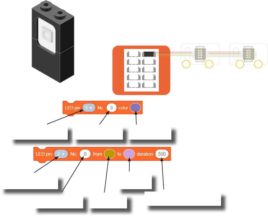
The Color LED is a LED composed of 3 smaller LEDs which emit red, green, and blue.
Each color’s brightness value can be congured individually. This can produce a wide
variety of colors. It is controlled over a special communication protocol which is dier-
ent from the basic “Digital Output” (used by Single-Color LED).
Usage
Color LED
This block congures what color a particular Color LED
displays.
Hub pin the 1st Color
LED is connected.
Transition from
this color.
Transition to
this color.
Color LED - Color Select block
Color LED - Color Transition block
This block causes a particular Color LED to transition from one
color to another color under a time span. (Note: This block must
complete its transition before proceeding to the next block in the
script.)
Index of the Color
LED to congure.
Color to change
the Color LED to.
Hub pin the 1st Color
LED is connected.
Set duration (in milliseconds)
for the transition.
• The Color LED connected
directly to the Hub is index 0.
• The Color LED connected
next in the chain is index 1.
• And so on.
Indexing
2/3
8/9
I2C A2/A3
I2C
I2C
4/5
A6/A7
A0/A1
6/7
IN INOUT OUT
Index of the Color
LED to congure.
ColorLED
Index: 0
ColorLED
Index: 1
131
Review of Modules
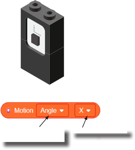
The Motion sensor is a triple axis accelerometer and gyroscope.
It is capable of measuring on the X, Y & Z axis the:
• Angle
• Acceleration
• Angular velocity
It uses the “I2C” communication protocol and must be connected to and “I2C” port on
mCenter+.
Motion
Motion - Read block
This block reads data from the Motion module. It is capable of retrieving the angle,
acceleration and angular velocity on the X, Y or Z axis.
Angle, acceleration, or
angular velocity to read.
On the X, Y or Z axis.

132
Review of Blocks
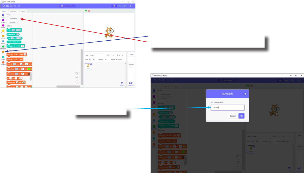
Addition Block
This block returns the sum of the left input and right input.
Division Block
This block returns the value of dividing the left input by the right input.
Multiplication Block
This block returns the product of the left input and right input.
Subtraction Block
This block returns the value of subtracting the left input by the right input.
Less Than Block
This block returns TRUE if the left input is less than the right input.
Equal Block
This block returns TRUE if the left input is equal to the right input.
Greater Than Block
This block returns TRUE if the left input is greater than the right input.
133
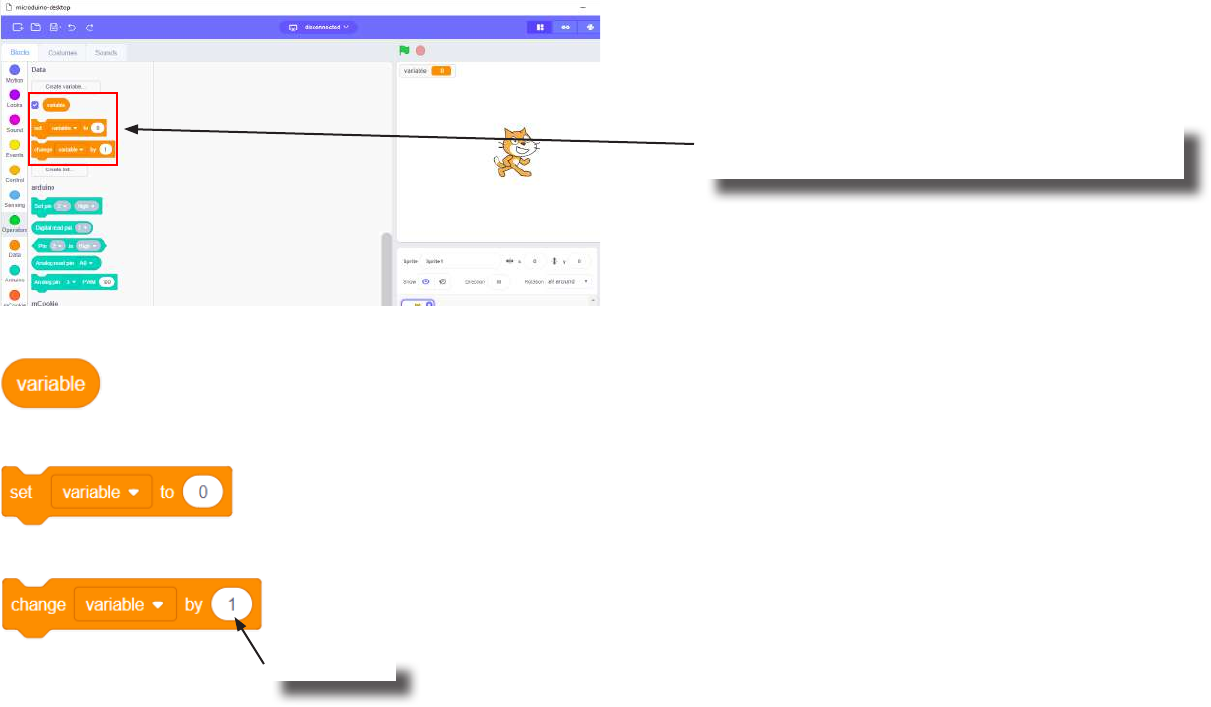
Review of Concepts
Creating a Variable in Scratch
Click on the “Variable” category.
Then click on the “Create variable...” button.
Name your variable.
134
Review of Concepts
Creating a Variable in Scratch (continued)
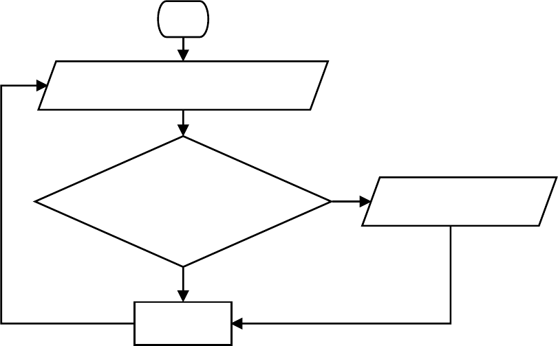
Several new blocks will appear which allows
access and modication of the new variable.
Variable Value block
Variable Set block
Variable Change block
This block returns the current value of the variable.
This block sets the value of the variable. It will overwrite the current value.
This block changes the variable value by adding the input value (negative values or blocks are accepted).
input value

135
The Problem
How can we detect large deceleration forces and indicated when detected?
136
Project Worksheet
Complete the worksheet below to your best abilities.
1. A solution.
2. List all the parts needed for the solution. What is the purpose of each part?
3. What is a simple explanation of the logic for the solution?
4. Create a ow chart of the solution.
5. How do you assemble and connect the modules for the solution?
6. Congure blocks to relate to the ow chart.
Use the Motion module to detect a large deceleration. Use a Color LED to indicate a large deceleration has
occured.

137
Project Worksheet - Answers
2. List all the parts needed for the solution. What is the purpose of each part?
1x mCenter+ - control the project, connect sensors and trinkets to project, and supply power.
2x Hub Connector Cable - connect sensors and trinkets to the mCenter+.
1x USB Cable - connect mCenter+ to a computer for charging and programming the project.
1x Motion - to detect large acceleration forces.
1x Color LED - indicate when a large acceleration is detected.
138
Project Worksheet - Answers
3. What is a simple explanation of the logic for the solution?
Large deceleration occurs when a sudden stop happens, such as when avoiding a car accident.
Use the Motion module to detect a large negative deceleration (sudden stop).
Use the Color LED to indicate when such force has been detected.
Read the “Y” acceleration. Check if it is a large negative value, which occurs during a sudden stop.
If there is a large value, then ash the Color LED to indicate it has occurred.
139
Project Worksheet - Answers
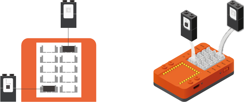
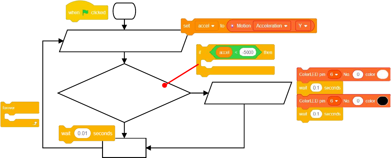
4. Create a ow chart of the solution.
Start
Read and store the "Y" acceleration value
from the Motion module
Does the "Y" acceleration
indicate a sudden stop?
(value < -5000)
Flash the Color LED
to indicate a sudden stop
Short delay
Loop
forever.
True
False
140
Project Worksheet - Answers
5. How do you assemble and connect the modules for the solution?
1. Connect the Motion module to a “I2C” pin.
2. Connect a Color LED (IN port) to pin 6/7.
3. Insert one end of the USB cable into mCenter+ and connect the other to a computer.
D2/D3
D8/D9
I2C A2/A3
I2C
D4/D5
A6/A7
A0/A1
I2C
D6/D7
141
Project Worksheet - Answers
6. Congure blocks to relate to the ow chart.
Start
Read and store the "Y" acceleration value
from the Motion module
Does the "Y" acceleration
indicate a sudden stop?
(value < -5000)
Flash the Color LED
to indicate a sudden stop
Short delay
Loop
forever.
True
False
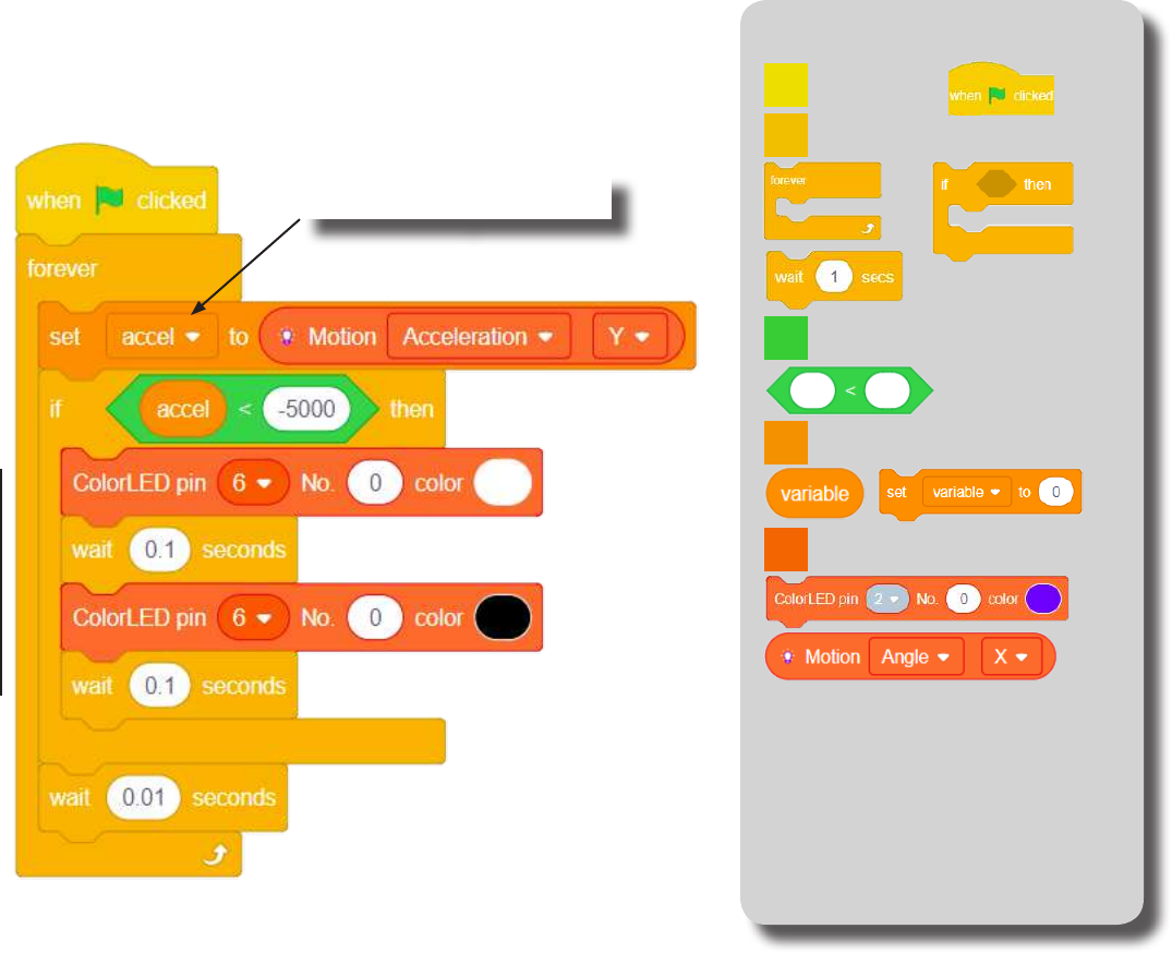
142
The Script Block Locator
(Create “accel” variable rst in
the variable tab.)
Click Green Flag to activate script.
Read and store the “Y” acceleration
from the Motion module.
Check if there is a large
negative acceleration (sudden stop).
If there is,
ash Color LED (pin 6).
Short delay before looping.
Loop.
Control
Events
mCookie
Data
Operators
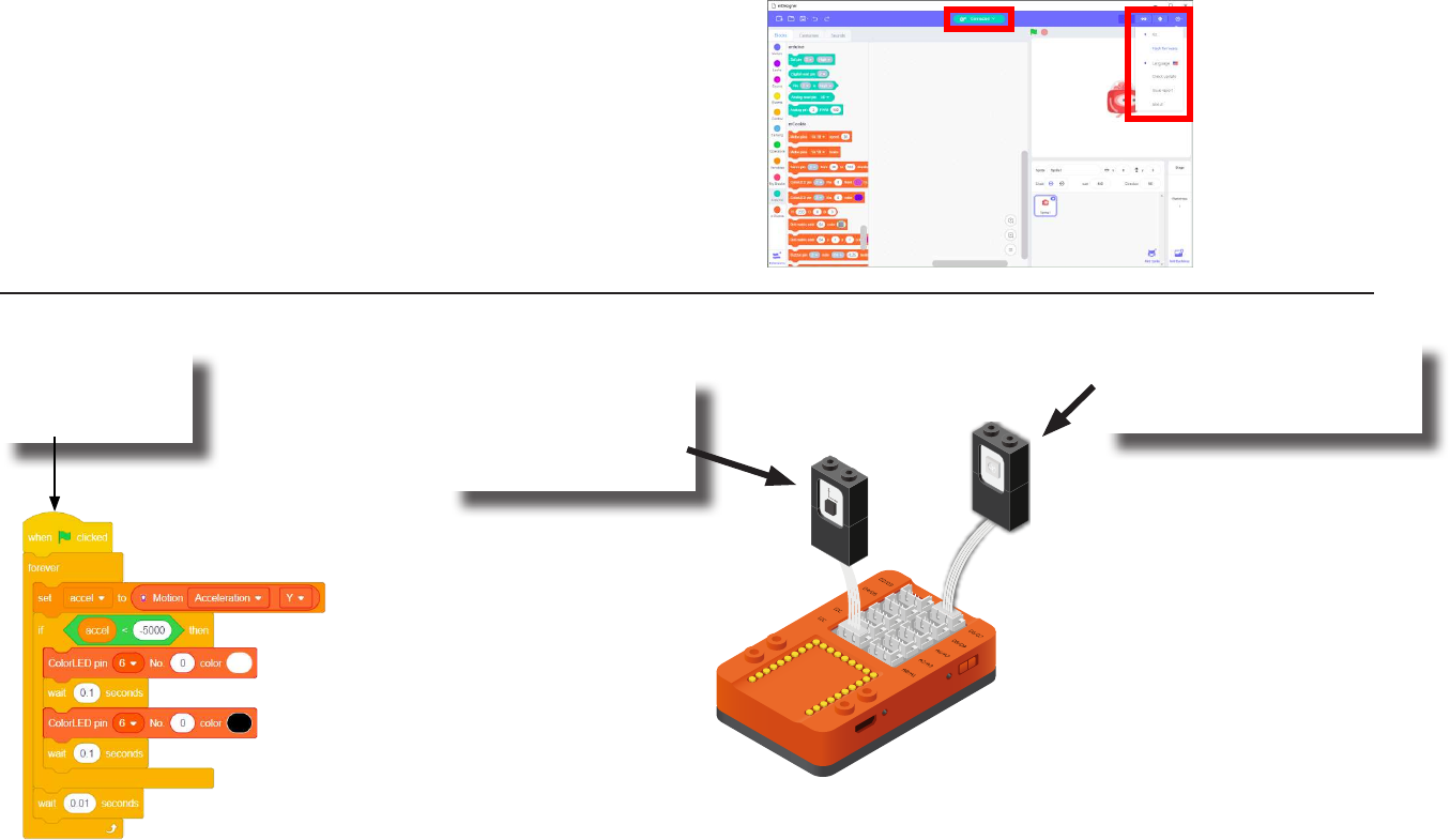
143
Click the green
ag to activate
the script.
1. Create a large
negative acceleration
force (sudden stop).
2. When a large negative
acceleration occurs, the
Color LED will ash.
Testing the Program
Important:
• Ensure that mCenter+ is on. Flip the switch on mCenter+
to turn it on. An LED on mCenter+ will light up to indicate
power is being supplied.
• Ensure you have selected the Serial Port and ashed the
special rmware (mCookie) rst before testing (this only
needs to be done once unless the rmware is overwritten).
• Ensure you have selected the Serial Port and connected
before testing.
Flash rmware
Select Serial Port
Testing:
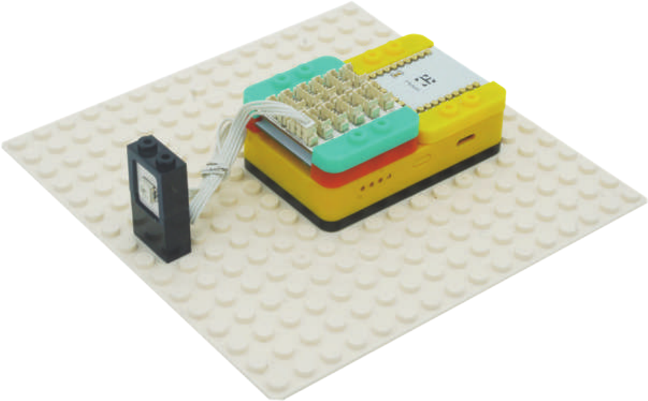
144
Create a Structure
Create a structure for the project using building blocks, paper, or other crafting materials.
145
Project Challenge
Create your own lighting eects when a sudden stop occurs.
How would you detect a large forward acceleration?
Modify the script to indicate when a large forward acceleration occurs.
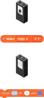
146
Review
Motion - module which detects motion such as roll, paw and yaw.
Motion - Read block - returns various motion readings from the Motion module.
Color LED - congurable to display a wide range of colors.
Color LED - Color Select block - congures what color a particular Color LED displays.
147
Expanding the Project
Research
Write down a way of expanding this project. Create it on your own.
Research more about the history of airbags.
Besides being in cars, what other places are airbags used?
__________________________________________________________
__________________________________________________________
__________________________________________________________
__________________________________________________________
__________________________________________________________
__________________________________________________________
__________________________________________________________
__________________________________________________________
__________________________________________________________
__________________________________________________________
__________________________________________________________
__________________________________________________________
__________________________________________________________
__________________________________________________________
__________________________________________________________
148
Wired RC Card
MIX 4 - Project 6
(Old Cards: MIX4B-01)

149
Radio controlled (or R/C) cars are battery/gas-powered model cars or trucks that can be controlled from a
distance using a specialized transmitter or remote. The term “R/C” has been used to mean both “remote
controlled” and “radio controlled”, where “remote controlled” includes vehicles that are connected to their
controller by a wire, but common use of “R/C” today usually refers to vehicles controlled by a radio-fre-
quency link. This section focuses on radio-controlled vehicles only.
Source: https://en.wikipedia.org/wiki/Radio-controlled_car
About RC Cars
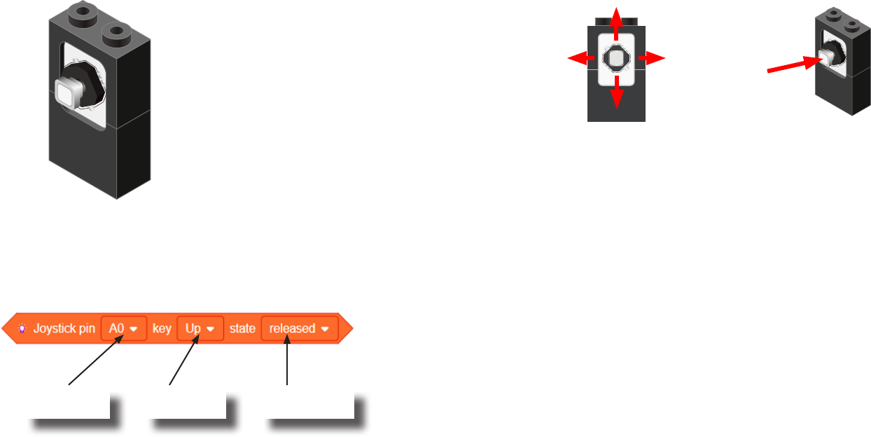
150
Review of Modules
A Joystick is an input module (sensor)
which can sense if the stick is in the
up, down, left or right positions.
In addition, it can sense if it is being
pressed (pressing directly on stick).
Joystick
Up
Left Right
Down
Press
Usage
The Joystick must be connected to an “Analog Read” compatible pin.
These are the pins prexed with an “A” (pins A0 to A7).
Joystick State block
On the dened Joystick pin, if the stick’s position (up, down, left,
right or center (pressed)) matches the state (released, pressed or
pressing), then this block returns TRUE.
Otherwise, this block returns FALSE.
Pin Joystick is
connected to.
Stick position
to check.
Stick position’s
state to match.
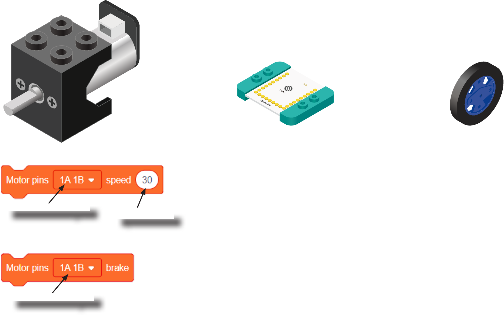
151
Review of Modules
A Motor is a electrical machine which converts electrical energy to mechanical energy. It
is capable of rotating clockwise and counter clockwise. It is controlled by a Motor Con-
troller. A Motor Controller can control up to 2 Motors. A Wheel can be attached to the
Motor.
Motor
Motor Controller Wheel
Motor - Set Speed block
This block sets the speed of the motor. Positive values turns the Motor in one direc-
tion. While negative values turns the Motor in the opposite direction. A value of 0
stops the Motor. Values between -255 and 255 are accepted. 255 is maximum clock-
wise speed. -255 is maximum counter-clockwise speed.
Motor - Brake block
This block sets the speed to 0 to stop the Motor.
Motor to congure.
Motor to congure.
Speed to set.

152
Review of Blocks
Addition Block
This block returns the sum of the left input and right input.
Division Block
This block returns the value of dividing the left input by the right input.
Multiplication Block
This block returns the product of the left input and right input.
Subtraction Block
This block returns the value of subtracting the left input by the right input.
Less Than Block
This block returns TRUE if the left input is less than the right input.
Equal Block
This block returns TRUE if the left input is equal to the right input.
Greater Than Block
This block returns TRUE if the left input is greater than the right input.
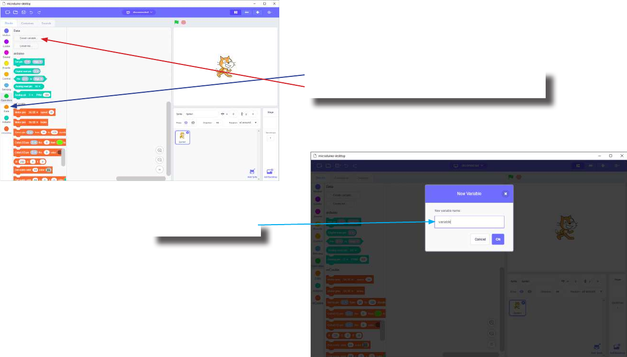
153
Review of Concepts
Creating a Variable in Scratch
Click on the “Variable” category.
Then click on the “Create variable...” button.
Name your variable.
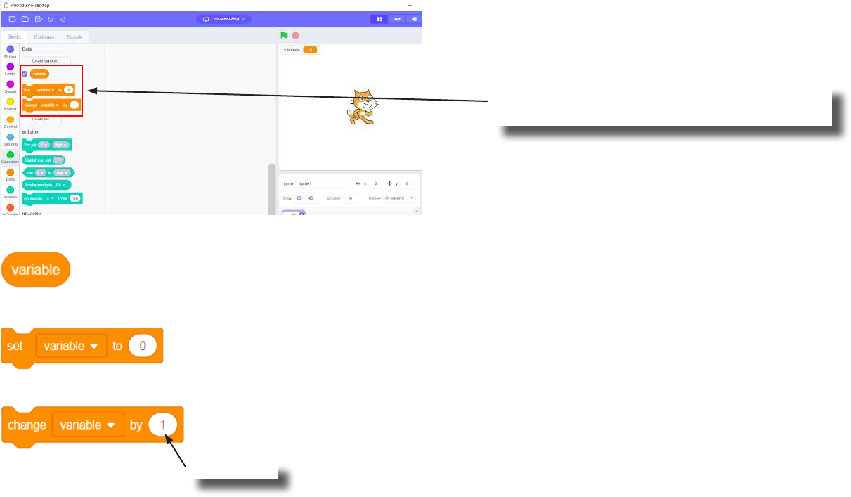
154
Review of Concepts
Creating a Variable in Scratch (continued)
Several new blocks will appear which allows
access and modication of the new variable.
Variable Value block
Variable Set block
Variable Change block
This block returns the current value of the variable.
This block sets the value of the variable. It will overwrite the current value.
This block changes the variable value by adding the input value (negative values or blocks are accepted).
input value

155
The Problem
How can we create a RC car controllable with a joystick module?