Microelectronics Technology AP5822 802.11a+b/g Outdoor AP/Bridge with int/ext Antenna User Manual MTI AP5822 USER S MANUAL for FCC v0 2
Microelectronics Technology Inc 802.11a+b/g Outdoor AP/Bridge with int/ext Antenna MTI AP5822 USER S MANUAL for FCC v0 2
user manual

A
AP
P5
58
82
22
2
U
Us
se
er
r’
’
s
s
M
Ma
an
nu
ua
al
l
8
80
02
2.
.1
11
1a
a+
+b
b/
/g
g
C
Ca
ar
rr
ri
ie
er
r-
-G
Gr
ra
ad
de
e
W
We
ea
at
th
he
er
rp
pr
ro
oo
of
f
WWiirreelleessss OOuuttddoooorr BBrriiddggee//AAPP SSyysstteemm
Document No.: 50-5000(REV:0.2)
July 14, 2004.
FCC ID: MAD-XXXX

802.11a Bridge AP5822 MTI Proprietary Page 2
Revision History
Revision
Date of Issue Scope Author
0.1 June 30, 2004
First draft Carl Yang
0.2 July 14, 2004
Carl Yang
FCC Notice:
This equipment has been tested and found to comply with the limits for a Class B digital
device, pursuant to Part 15 of the FCC Rules. These limits are designed to provide
reasonable protection against harmful interference in a residential installation. This
equipment generates, uses and can radiate radio frequency energy and, if not installed and
used in accordance with the instructions, may cause harmful interference to radio
communications. However, there is no guarantee that interference will not occur in a
particular installation. If this equipment does cause harmful interference to radio or television
reception, which can be determined by turning the equipment off and on, the user is
encouraged to try to correct the interference by one or more of the following measures:
n Reorient or relocate the receiving antenna.
n Increase the separation between the equipment and receiver.
n Connect the equipment into an outlet on a circuit different from that to which the receiver
is connected.
n Consult the dealer or an experienced radio/TV technician for help.
Changes or modifications not expressly approved by the party responsible for compliance
could void the user‘s authority to operate the equipment.
This device and its antenna(s) must not be co-located or operating in conjunction with any
other antenna or transmitter.
The equipment version marketed in US is restricted to usage of the channels 1-11 in 2.4GHz
band only.

802.11a Bridge AP5822 MTI Proprietary Page 3
This device complies with Part 15 of the FCC Rules. Operation is subject to the following two
conditions: (1) This device may not cause harmful interference, and (2) this device must
accept any interference received, including interference that may cause undesired operation.
FCC Caution: Any changes or modifications not expressly approved by the party responsible
for compliance could void the user's authority to operate this equipment.
FCC Radiation Exposure Statement:
This equipment complies with FCC radiation exposure limits set forth for an uncontrolled
environment. End users must follow the specific operating instructions for satisfying RF
exposure compliance.
Because standard antenna-connectors are used, this device is for professional installation
only.
For the safety reason, people should not work in a location where the RF Exposure
exceeds the limits. To get this, people who work with the antennas should be aware of the
following rules:
1). When using the 2.4GHz 8dbi or the 5GHz 8dbi or the 5GHz 17dbi antenna, the user
should keep at least 20 cm or more separation distance with the antenna.
2). When using the 5GHz 23dbi antenna, the user should keep at least 30 cm or more
separation distance with the antenna.

802.11a Bridge AP5822 MTI Proprietary Page 4
Disclaimer
MTI AP5822 Weatherproof Wire less Outdoor Bridge System User’s Manual
Document No.: 50-5000(REV:0.35), November 13, 2003.
COPYRIGHT © 2003 by Microelectronics Technology INC.
ALL RIGHTS RESERVED
No part of the publication may be reproduced, transmitted, transcribed, stored in a retrieval
system, or translated into any language or computer language, in any form or any means,
electronic, magnetic, chemical, manual or otherwise, without the prior written permission of
Microelectronics Technology Inc. (MTI). No.1, Innovation RD II, Hsinchu Science-Based
Industrial Park, Hsinchu 300, Taiwan, R.O.C.
MTI AP5822 is a registered trademark of Microelectronics Technology Inc.
Printed in the Taiwan, R.O.C.
The instructions in this manual have been carefully checked for accuracy and are presumed to
be reliable. The accuracy and adequacy of this document are the responsibilities of
Microelectronics Technology Inc. Please address any comments or corrections to
Microelectronics Technology Inc.

802.11a Bridge AP5822 MTI Proprietary Page 5
Warranty
This Microelectronics Technology Inc. product is warranted against defects in materials and
workmanship for a period of one year from date of shipment. During the warranty period,
Microelectronics Technology Inc. will, at its option, either repair or replace products which to be
defective.
For warranty service or repair, this product must be returned to a service facility designated by
MTI. Buyer shall prepay shipping charges to MTI and MTI shall pay shipping charges to
return the product to Buyer. However, Buyer shall pay all shipping charges, duties, and taxes
for products returned to MTI from another country.
MTI warranty that its software and firmware designated by MTI for use with our product will
execute its programming instructions when properly installed on this product. MTI does not
warrant that the operation of the product, or software, or firmware will be uninterrupted or
error free.
Limitation of Warranty
The foregoing warranty shall not apply to defects resulting from improper or inadequate
maintenance by Buyer, Buyer-supplied software or interfacing, unauthorized modification or
misuse, operation outside of the environment specifications for this product, or improper site
preparation or maintenance.
No other warranty is expressed or implied. MTI specifically disclaims the implied warranties of
merchantability and fitness for a particular purpose.
Trademark Disclosures
MTI has made every effort to provide disclosures when using trademarks owned by other
companies. Trademarked designations appear throughout this publication. The publisher
states that it is using the designations only for editorial purposes, and to the benefit of the
trademark owner with no intent to infringe upon that trademark. The following trademarks are
found in this manual:
ATHEROSTM is a registered trademark of Atheros Communications Inc.

802.11a Bridge AP5822 MTI Proprietary Page 6
Manual Conventions
The following conventions are followed in this manual:
Bold
Bold type within paragraph text indicates commands, file names, directory
names, paths, output, or returned values.
Italic Within commands, italics indicate a variable that the user must specify.
Titles of manuals or other published documents are also set in italics.
Courier The courier font indicates output or display.
[]
Within commands, items enclosed in square brackets are optional parameters
or values that the user can choose to specify or omit.
{}
Within commands, item enclosed in braces are options from which the user
must choose.
| Within commands, the vertical bar separates options.
… An ellipsis indicates a repetition of preceding parameter.
> The right angle bracket separates successive menu selection.
Notices
NOTE: This message denotes neutral or positive information that calls out
important points to the text. A note provides information that applies only in
special cases.
Caution: Cautions call special attention to hazards that can cause system damage or data
corruption, to a lesser degree than warnings.
Warnings: Warnings call special attention to hazards that can cause system damage, data
corruption, personal injury, or death.

802.11a Bridge AP5822 MTI Proprietary Page 7
Preface
Microelectronics Technology Inc. (MTI) is very pleased for you purchase in this product. MTI
AP5822 is a cost-effective way to expand or replace your local, wired networks (LANs). With this
system, your wired networks can communicate with one another wired networks.
Building to Building Connection
MTI 802.11a wireless outdoor turbo bridge AP5822 is a wireless building-to-building bridge
solution. AP5822 provides data rate up to 108 Mbps and is best suited for enterprises,
campus or off-site locations that require LAN or Internet access without the availability of
wired networks to extend network coverage.
AP5822 provides point-to-point and point-to-multi-point connection capabilities. The
wireless building-to-building bridging solution contains a state-of-the-art wireless Bridge, high
gain performance 17dBi flat patch antenna and power-over-Ethernet technology. For further
protection, the bridge and power-over-Ethernet adapter have built in lightning protector.
Last Mile Solution
MTI’s AP5822 provides the alternative solution for last-mile connection. By leveraging the
802.11’s volume power and low cost, AP5822 Link provides very cost effective solution to
carriers. With the cost effective wireless last mile solution, service provider can have fast
deployment (time-to-market) and successful business models.
This document was written for user of the MTI AP5822 Weatherproof Wireless Outdoor
Bridge System. First, we will introduction our system, help you to connect it and install the
software, and describe the entire feature about the system.
This manual contains information on installing, operating, and maintaining the MTI AP5822.
Installation tasks include mechanical installation of the MTI AP5822, connecting external
equipment to the MTI AP5822, and configuring the system. Operation tasks include modify
operating parameters, monitoring status, and maintaining the system through troubleshooting
and system repair procedures. This manual is intended for those people who install and
operate the MTI AP5822 system.
Docum entation
The accompanying documentation comprises:
Manual - Hardware installation, description of the functions, operating modes and sample
configurations
CD containing electronic documentation - Complete set of manuals for the product family,
technical basics (such as information on wireless networks, general network technology,
TCP/IP etc.), a workshop with detailed descriptions of sample applications, and a reference
section including comprehensive description of the menus.

802.11a Bridge AP5822 MTI Proprietary Page 8
Table of Contents
Revision History......................................................................................................................................2
Disclaimer.................................................................................................................................................4
Warranty...................................................................................................................................................5
Limitation of Warranty ............................................................................................................................5
Trademark Disclosures ..........................................................................................................................5
Manual Conventions...............................................................................................................................6
PREFACE................................................................................................................................................7
Building to Building Connection............................................................................................................7
Last Mile Solution....................................................................................................................................7
Documentation........................................................................................................................................7
TABLE OF CONTENTS.........................................................................................................................8
CHAPTER 1 INTRODUCTION.......................................................................................................... 10
1-1 System Requirements .................................................................................................................. 10
1-2 Product Configurations ................................................................................................................. 10
1-3 Specification................................................................................................................................... 11
1-4 Hardware Architecture.................................................................................................................. 11
CHAPTER 2 HARDWARE INSTALLATION................................................................................... 13
2-1 Unpacking the Equipment............................................................................................................ 13
2-2 Verifying the System Configuration............................................................................................ 13
2-3 Installation Kit.................................................................................................................................13
2-4 Grounding ....................................................................................................................................... 14
2-5 ESD Protection.............................................................................................................................. 14
2-6 Outline of MTI AP5822................................................................................................................. 15
2-7 Installing the ODU......................................................................................................................... 16
2-8 Connecting the cable.................................................................................................................... 16

802.11a Bridge AP5822 MTI Proprietary Page 9
2-9 Align the Antenna (TBD)...............................................................................................................17
CHAPTER 3 BRIDGE NETWORK CONFIGURATION .................................................................18
3-1 Bridge Network Connections .......................................................................................................18
3-2 Network Configuration ..................................................................................................................19
3-3 Bridge Initial Configurations .........................................................................................................20
3-4 Web Browser..................................................................................................................................21
3-5 Bridge Web Server........................................................................................................................22
3-6 Configuration Windows.................................................................................................................24
3-7 Working with Configuration Windows.........................................................................................24
3-8 System Basic Configuration Window .........................................................................................25
3-9 System Advanced Configuration Window .................................................................................26
3-10 Advanced Setup Window...........................................................................................................27
3-11 Firmware Update Configuration Window.................................................................................27
3-12 Statistics Windows ......................................................................................................................28
3-13 Bridge Statistics ...........................................................................................................................28
3-14 Station Statistics ..........................................................................................................................30
3-15 Bridge setup window...................................................................................................................32
APPENDIX A ACRONYMS & ABBREVIATIONS...........................................................................33

802.11a Bridge AP5822 MTI Proprietary Page 10
Chapter 1 Introduction
MTI 802.11a wireless outdoor
turbo bridge, AP5822 is a
wireless building-to-building
bridge solution, AP5822 provide
the data rate up to 108 Mbps that
is best suited for enterprises,
campus or off-site locations that
require LAN or Internet access
without the availability of wired
networks to extend the network
coverage. AP5822 provides the
point to point and point to
multi-point connection.
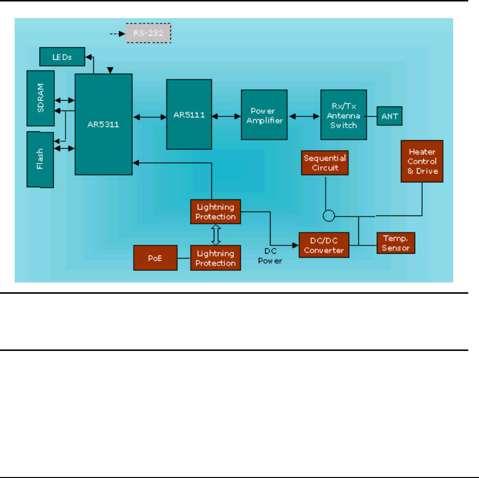
The wireless building-to-building
bridging solution contains a state
of the art wireless Bridge, high
gain performance 17dBi flat panel
antenna and Power over Ethernet.
For further protection, the bridge
and Power over Ethernet adapter
have build in lightning protector.
Rates of 6 to 54 Mbps are
supported in standard IEEE 802.11a modes, and up to 108 Mbps in Atheros Turbo Mode. All
802.11a transmission rates are supported across the 5.15 to 5.85 GHz spectrum.
1-1 System Requirements
The Bridge contains a small boot executive that allows the main operating system software to
be downloaded using the Ethernet port over an FTP connection. The Operating system
software can also reside in the Flash memory of the Bridge, which allows booting without the
need to download the operating system from the host PC over an FTP connection. A
configuration file is created in Flash memory to store user-configurable parameters. A
terminal or PC with an Ethernet connection is required to perform the initial Bridge
configuration. An FTP server is required for firmware update to the Bridge.
1-2 Product Configurations
The base hardware is an outdoor mountable metal enclosure. The AP5822 can be managed
via the network station remotely. The following are available product configurations:
n Fast Ethernet managed 802.11a wireless outdoor turbo bridge
n Outdoor Mounting Kit
n One POE Power Injector

802.11a Bridge AP5822 MTI Proprietary Page 11
n One POE Ethernet cable
n One POE Power Core
n User’s Manual
n CD ROM
1-3 Specification
n Radio
802.11a 802.11b/g
l Operating Band 5.25 ~ 5.35GHz 2.4 ~ 2.4835 GHz
5.725 ~ 5.85 GHz
l Operating Channels 9 non-overlapping Channels 3 non-overlapping Channels
l Transmit output power +20 dBm for 6 ~ 36 Mbps +20 dBm for 6 ~ 36 Mbps
+18 dBm for 48 Mbps +19 dBm for 48 Mbps
+16 dBm for 54 Mbps +18 dBm for 54 Mbps
l Receive Sensitivity -91 dBm for 6Mbps -91 dBm for 6Mbps
-89 dBm for 12Mbps -89 dBm for 12Mbps
-87 dBm for 18Mbps -87 dBm for 18Mbps
-84 dBm for 24Mbps -84 dBm for 24Mbps
-80 dBm for 36Mbps -80 dBm for 36Mbps
-75 dBm for 48Mbps -75 dBm for 48Mbps
-70 dBm for 54Mbps -70 dBm for 54Mbps
l Antenna Build in +17dBi Flat Panel External + 8 dBi Omni
External +23 dBi Flat Panel
External + 8 dBi Omni
n Environment
l Operating Temperature -33 ~ +55°C
l Storage Temperature -40 ~ +80°C
l Humidity 0 ~ 95%, non-condensing
l Altitude 15,000 feet
l Lightning-Protection Built-In Surge Protection
n Interface
l LAN 10/100 Ethernet Port
n Power
l POE 48V DC, 18W Max
802.11a Bridge AP5822 MTI Proprietary Page 12
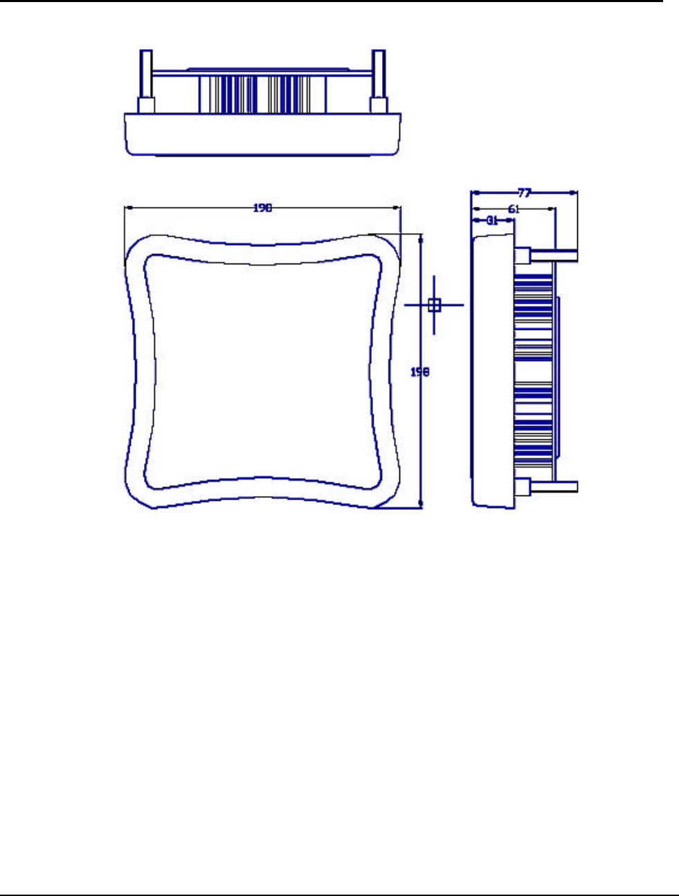
n Physics
l Dimensions 198 x 198 x 63 mm
l Weight <2.0Kg
n Miscellaneous
l Security 128-bit WEP
l Management web-based GUI
l Software Upgrade TFTP
l VPN Pass-through Yes
1-4 Hardware Architecture
WARNING: If end users are allowed to upgrade firmware through the FTP server, confirm that the End
User License Agreement (EULA) covers upgrades to the firmware. The Reference Design upgrade code
permits direct upgrades of the Bridge from the configuration screen if a web browser is used. As a
precaution, also use the EULA as the FTP startup text in the event some end users log in to the FTP
server manually.
Use the Bridge Web Server for firmware updates. Refer to “Firmware Update Configuration
Window” for information on the web server.

802.11a Bridge AP5822 MTI Proprietary Page 13
Chapter 2 Hardware Installation
This chapter provides installation procedures are generally outlined as follows:
n Verify system configuration
n Installing the ODU
n Installing the POE
n Mounting and alignment the antenna
n Connecting external equipment
You may need to use Web Browser to
change or set the MTI AP5822 system’s
operating parameters. Refer to chapter 3,
Bridging network attachment and configuration, for more information.
2-1 Unpacking the Equipment
The tools required for unpacking the system equipment are:
n Utility knife
n Clean, flat working surface
Open the shipping containers, carefully remove the equipment and place it on a clean, flat
working surface. Save the shipping and packing material in case the equipment has to be
returned.
Check the equipment and installation kits against the packing list to ensure that the equipment
part numbers, parts, and ancillary equipment included in the shipment match what is specified
on the packing list. Shipments consist of an ODU and an installation kit in one container. Verify
the configuration as described in verifying the System Configuration. If there are discrepancies
between the packing list and the equipment received, contact your sales representative.
Inspect the equipment for any type of shipping damage. If any part of the shipment is damaged,
contact your sales representative for repair or replacement instructions.
2-2 Verifying the System Configuration
The MTI AP5822 system consists of an Outdoor Unit (ODU), POE and an installation kit.
2-3 Installation Kit
Most of the materials needed for installation are supplied with the system. Some tools and
equipment must be supplied by the user. Table lists materials in a typical installation kit. Refer
to the packing list for a description of the exact contents.

802.11a Bridge AP5822 MTI Proprietary Page 14
Table Installation Kits (for 2” Steel or Stainless Steel Tube)
Item
Description Quantity
1 M-TYPE PLATE 1EA
2 L-TYPE PLATE 1EA
3 U-TYPE PLATE 1EA
4 NUT FLANGE M8-1.25 SS (PLATE ASM) 3EA
5 NUT FLANGE M8-1.25 SS (HOUSING ASM) 4EA
2-4 Grounding
Proper grounding of equipment and structures is essential to prevent electrical damage to the
MTI AP5822 system.
Grounding of all equipment at a radio site is required. Without proper grounding, voltage
potentials between components of the system can cause electrical damage when
interconnecting cables are installed.
It is recommended that the ODU be installed with lightning rod protection. Also, to avoid surge
current caused by lightning circulating to the equipment earth system, connect the equipment
earth system (true ground) to the lightning rod ground.
Please connect the ground node to the existing ground.
Note: Ground wires and hardware are not provided in the installation kit.
2-5 ESD Protection
ESD (electrostatic discharge) can damage electronic components. Even if components remain
functional, ESD can cause latent damage that results in premature failure. Personnel and
equipment must be properly grounded. Always wear proper ESD grounding straps during
equipment installation, maintenance and repairs. Connect your ESD grounding strap to the
ESD connector.
802.11a Bridge AP5822 MTI Proprietary Page 15
2-6 Outline of MTI AP5822
802.11a Bridge AP5822 MTI Proprietary Page 16
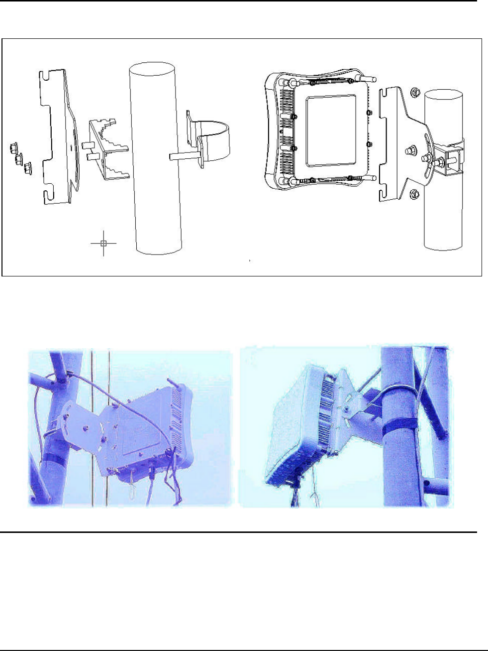
2-7 Installing the ODU
The MTI AP5822 can be mount on a 2” Steel or Stainless Steel Tube. You can reference the Figure.
ODU Configuration
You can refer the photo here for installation.
2-8 Connecting the cable
An Ethernet cable connects the ODU to the POE output port. The cable connects power to the ODU
and allows Ethernet data to flow between Stations with Bridge system. Another Ethernet cable
connects the station to POE input port. AC power is applied to the bridge system by connect it to POE
AC adapter.

802.11a Bridge AP5822 MTI Proprietary Page 17
2-9 Align the Antenna (TBD)
Antenna alignment is performed with both the near-end and the far-end terminals operating.
The antenna position is adjusted while monitoring the RSSI for antenna alignment voltage. The
higher the RSSI voltage reading is, the stronger the signal. The range of the RSSI voltage
reading is from 0 to 3.28VDC, and the resolution is 256 divisions.
Caution: To ensure optimum system performance, the main lobe of the antenna must be aligned with the center
of the far end antenna. Rotate the antenna through the range of radiated power so the main lobe can be positively
identified. Each side lobe is approximately 20 dB lower than the preceding lobe as you move away from the main
lobe.
This antenna alignment procedure is applicable to both protected and non-protected system
configurations. Align the antenna as follows:
Note: Repeat this procedure if the initial alignment does not produce the correct RSSI reading.
1. Consult your path calculation and adjust the radio’s attenuation level, so do not exceed
the maximum receiving signal level.
2. Verify that the Bridge at the far end is operational.
3. At the near-end Bridge, remove the protective cap from the RSSI BNC connector.
4. Connect a voltmeter to the RSSI connector and set the voltmeter to measure VDC.
5. Pivot the antenna slowly in the azimuth direction. Monitor the voltmeter and locate the
position where the voltage is minimum (null) and record the reading.
6. Monitor the voltmeter and pivot the antenna in the elevation direction. Pivot the antenna
to the position where the voltage is minimum on the voltmeter and record the reading.
7. Repeat these steps as necessary to get an accurate reading.
8. Tighten all fasteners and check that the null has not changed. If the null has changed,
repeat the procedure until the null is maintained after tightening the fasteners.
9. Disconnect the voltmeter and replace the RSSI protective cap.
Note: The signal level over the link is not optimal until both antennas are correctly aligned.
802.11a Bridge AP5822 MTI Proprietary Page 18
Chapter 3 Bridge Network Configuration
This chapter provides procedures for connecting and configuring the Bridge to a Host PC
(HPC). Configuration can be performed either from a web browser accessing the built-in web
server. For detailed information on using the web server, refer to “Bridge Web Server”.
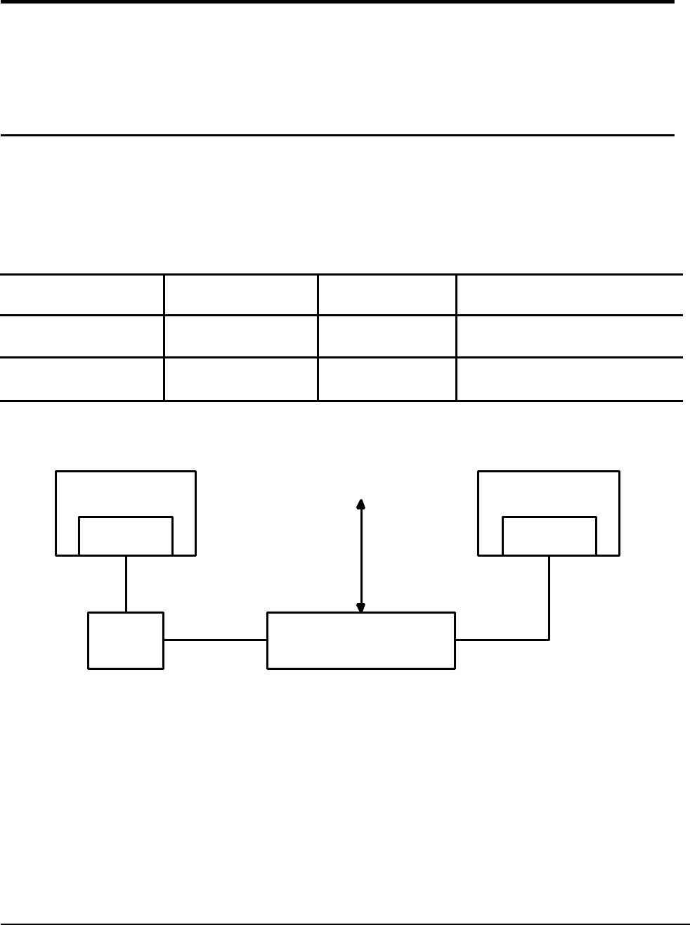
3-1 Bridge Network Connections
Connect the HPC to the Bridge using one of the following two methods:
n Use an Ethernet crossover cable (not supplied) to connect directly to the Ethernet port of
the HPC. For more information on Ethernet cables, see Table.
Table Ethernet Port Configuration
Ethernet Port Number
Dumb Hub or Switch
Computer Auto-Sensing Hub or Switch
0 Crossover cable Straight cable Crossover or straight cable
1 Straight cable Crossover cable Crossover or straight cable
n Use standard Ethernet cables (not supplied) to connect through a hub or Ethernet switch.
See Figure for an example of the Bridge to the HPC connections.
Host PC(HPC) Bridge
Ethernet
Hub/Switch
Ethernet Port
Ethernet Cable
Ethernet Cable
Power On Ethernet (POE)
Ethernet Cable
Ethernet Port
INPUT OUTPUT
AC
Bridge to the HPC connection
To establish the network connections, connect the Bridge Ethernet port to the HPC Ethernet
card through the Ethernet hub/switch or an Ethernet crossover cable.
802.11a Bridge AP5822 MTI Proprietary Page 19
3-2 Network Configuration
Follow these steps to configure the HPC for Bridge network control:
n From the HPC’s Start menu, choose Settings and open the Network and Dial-up
Connections dialog box.
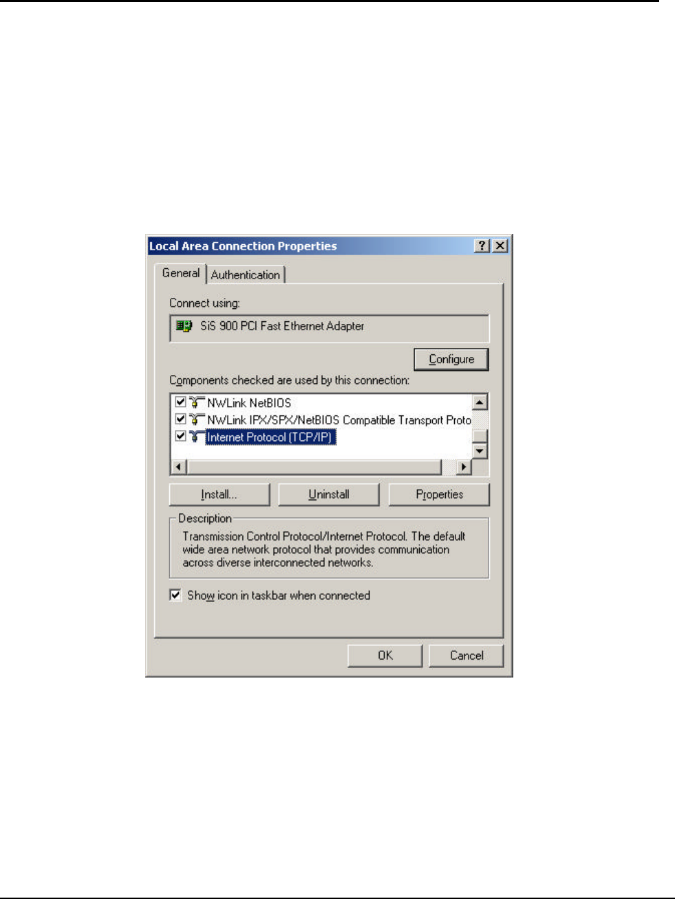
n Right-click on the Local Area Connection icon that belongs to the Ethernet controller
connected to the Bridge, and select Properties.
n Within the Local Area Connection Properties dialog box, choose Internet Protocol
(TCP/IP) and click Properties.
Local Area connection properties window
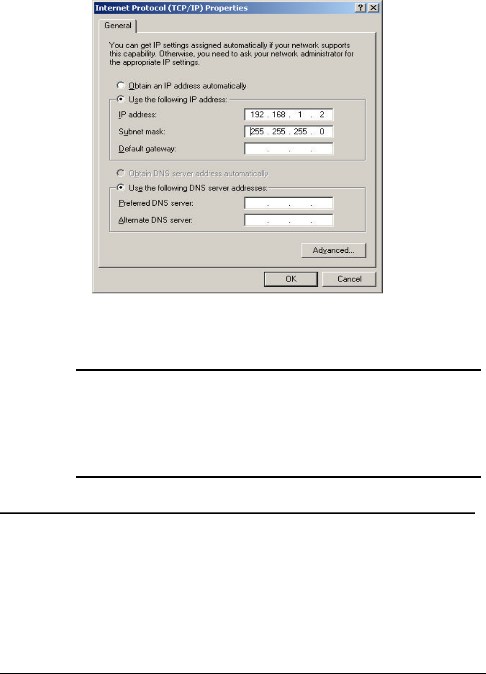
n Configure the following setting for the Ethernet connection in the Internet Protocol
(TCP/IP) Properties dialog box.
• User IP Address (Don’t use the same IP address as your bridge)
• LAN Mask Setting
• Gateway Setting
• DNS Server Setting
802.11a Bridge AP5822 MTI Proprietary Page 20
Internet protocol (TCP/IP) Properties dialog box
n Click OK to continue and close the Internet Protocol Properties dialog
Notices
If you use the same HPC to
ping/connect the same IP bridges, you must clear
the route table in the HPC first. Otherwise, you won’t find other bridge. In
Microsoft Windows system, you can do it by enter following command in DOS
command mode: (assume the ARP program is under the path
of
c:\windows\system32)
C:\windows\system32>ARP –D
3-3 Bridge Initial Configurations
This section describes how to configure the Bridge after booting from Flash memory. Refer to
“Firmware Update Configuration Window” to load the Operating image file to the Flash file
system, if the operating system software should be updated.
Configure the Bridge for its channel frequency and Service Set Identifier (SSID) unique to the
application. This configuration can be done either through a web browser with access to the
built-in Bridge web server. The Bridge can be configured at any time to tailor it for the
application environment. For more information on configuring the Bridge using the web
browser, refer to “Bridge Web Server”. The following description illustrates the use of the
web browser
802.11a Bridge AP5822 MTI Proprietary Page 21
3-4 Web Browser
Follow these steps to configure the channel frequency and SSID using a web browser:
n Launch a web browser (Netscape Navigator or Internet Explorer are examples of
commonly used web browsers).
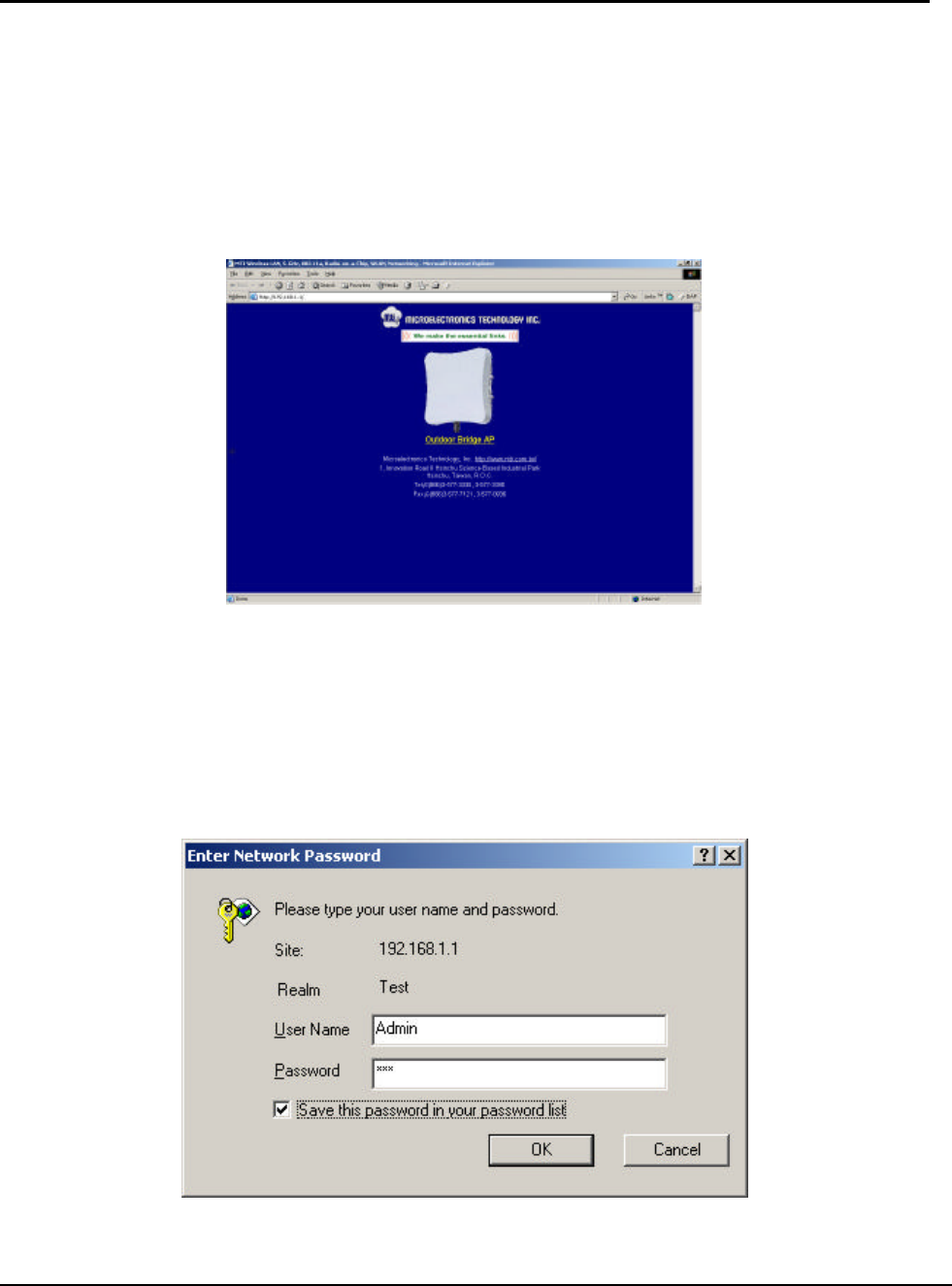
n From the HPC, enter the IP address that is assigned to the Bridge as the URL
address, for example http://192.168.1.1.
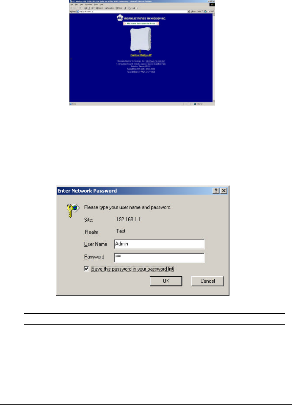
The Bridge Web Server homepage will appear (see Figure).
BRIDGE Web Server Homepage
n Select the Bridge Web Server hotlink.
n A dialog box appears requesting login authorization. When prompted, enter the
following information to log in:
Log in: Admin (case-sensitive)
Password: 5up
n Click OK to complete the login process. The Basic Configuration window appears (see
Figure).
802.11a Bridge AP5822 MTI Proprietary Page 22
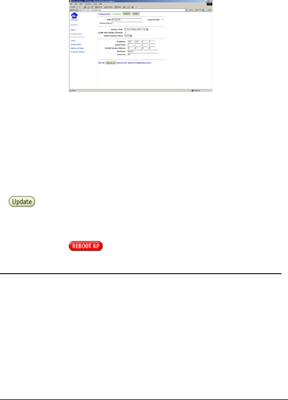
System Basic Configuration Window
n Enter the SSID (name or address) for the Bridge in the SSID field. The SSID must be
1–32 characters in length. To configure a single SSID to have more than one Bridge in
a single SSID, specify a unique System Name for each Bridge within that single SSID.
n Specify the radio frequency operation of the Bridge by selecting the desired value from
the Radio Channel drop-down menu. This value specifies the frequency the stations
(STAs) under the Bridge are associating with in Infrastructure mode.
n Note that the radio channel is specified using the IEEE 802.11a standard.
n Click Update to commit the changes.
Change other settings at this time. After all configuration changes are complete; reboot the
Bridge to enable them. To reboot the Bridge, click on the REBOOT Bridge button that
appears.
Reminder: Click the buttons for changes to take effect.
3-5 Bridge Web Server
Configure the Bridge either through a web browser interface to the Bridge web server. The
web server resides in the Bridge and is accessible from any station (STA) that is connected to
the Bridge Infrastructure network.
Accessing the Bridge Web Server
Follow these steps to access the Bridge Web Server:
n Launch a web browser (Netscape Navigator or Internet Explorer are examples of
commonly used web browsers).
n From the HPC, enter the IP address that is assigned to the Bridge as the URL address.
For example, enter http://192.168.1.1.
The Bridge Web Server homepage appears (see Figure).
802.11a Bridge AP5822 MTI Proprietary Page 23
Bridge Web Server Homepage
n Select the MTI Outdoor Bridge Web Server hotlink.
n A dialog box appears requesting login authorization. When prompted, enter the
following information to log in:
Log in: Admin (case sensitive)
Password: 5up
n Click OK to complete the login process.
NOTE: The web browser must support frames and Java script must be enabled.
The Bridge Web Server Basic Configuration window appears (see Figure.)
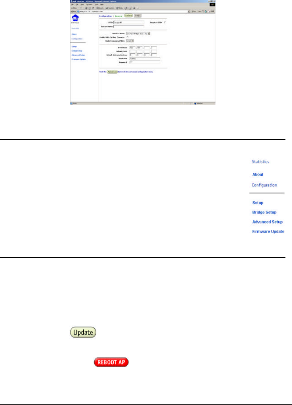
802.11a Bridge AP5822 MTI Proprietary Page 24
Basic Configuration Window
3-6 Configuration Windows
The Web Server Configuration windows allow viewing and editing of
configuration information for the Bridge. The Web Server provides
configuration windows for:
n System configuration parameters
n Radio configuration parameters
n Statistics
n Firmware updates
To access any of these Bridge configuration screens, click on the desired
hotlink from the navigation bar on any configuration screen (see Figure)
3-7 Working with Configuration Windows
The Web Server Configuration windows provide a user-friendly interface to aid in quick
configuration of the Bridge. After making any additions or changes to any configuration
window, update the configuration file to save the changes. The new configuration is not in
effect until the Bridge is rebooted.
Follow these steps to update configuration files:
n Enter the configuration updates or changes in the appropriate configuration fields.
n Click Update.
n Click Reboot Bridge to make the changes effective.
Reminder: Click the buttons for changes to take effect.
The web server loses connectivity with the Web Server as the Bridge reboots.
To reestablish the connection with the Web Server, wait until the Bridge has completed
rebooting and navigate to the Web Server to resume communication.
802.11a Bridge AP5822 MTI Proprietary Page 25
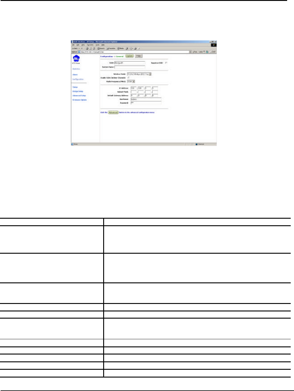
3-8 System Basic Configuration Window
The System Basic Configuration window allows the setting of general operating information
for the Bridge. Click on Configuration from any window to access the System Basic
Configuration window (see Figure).
Bridge System Basic Configuration Window
Set the value of default gateway address to PC IP or router port IP.
Other settings can also be changed at this time.
Table A-2 summarizes the data fields on the System Basic Configuration window.
Table A-2. System Basic Configuration Window Field Descriptions
General Configuration Field Description
SSID Identification of the Bridge. Enter a number or address betwe
en 1 and 32
characters in length that the STAs
are associating with in Infrastructure
mode. More than one Bridge in an SSID can be specified here. Use
the
System Name field to uniquely identify each Bridge.
Suppress SSID Use the checkbox to prevent broadc ast of the Bridge’s
SSID in
beacons. When enabled, the SSID in beacons
are not transmitted and
only those STAs with prior knowledge of an Bridge ’
s SSID can
associate with that Bridge.
System Name Specifies a unique name for Bridge. Enter a unique text str
ing of up to 32
characters in length. Both bridge A and B must have the same system
name.
Wireless Mode The wireless LAN mode specifies both frequency range and data rates.
Enable 5GHz Outdoor Channels Click this button to Enable 5GHz radio operation
Radio Frequency (MHz) Select the desired frequency of operation from the drop-down menu.
The
radio frequencies that appear in the Radio Channel drop-
down menu are
dependent on the wireless mode selection.
IP Address Specifies the IP address of the Bridge.
Subnet Mask Specifies the subnet mask for the Bridge.
Default Gateway Address Specifies the default gateway for the Bridge.
User Name Specifies the user name.
Password Specifies the pas sword.
802.11a Bridge AP5822 MTI Proprietary Page 26
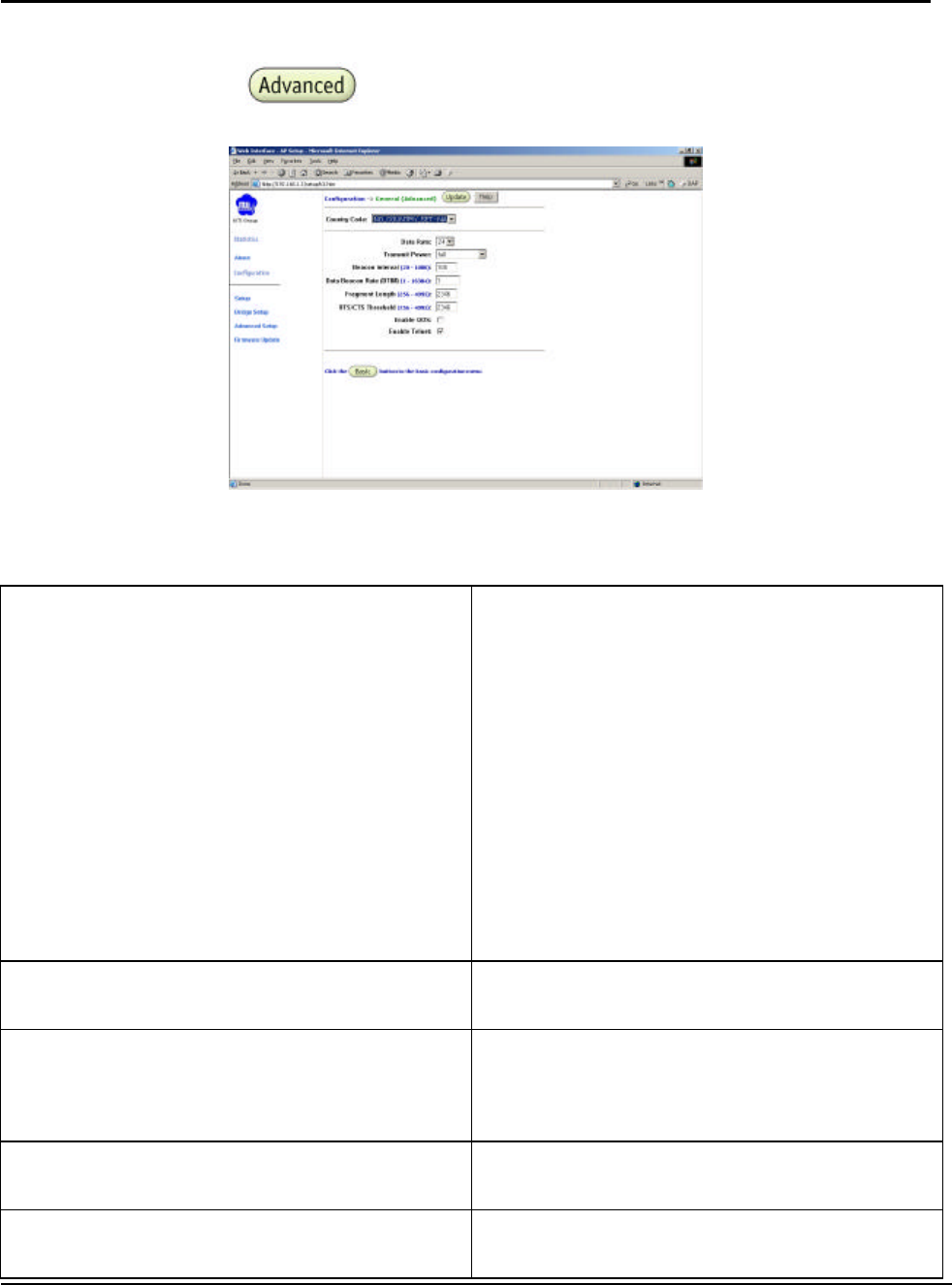
3-9 System Advanced Configuration Window
The System Advanced Configuration window allows the setting of detail operating information
for the Bridge. Click on button from any window to access the System Advanced
Configuration window (see Figure below).
Table summarizes the data fields on the Radio Advanced Configuration window.
Table Radio Advanced Configuration Window Field Descriptions
Advanced Configuration Field Description
Data Rate Specifies rate of data transmission. Select the
desired rate from the drop-down menu. The
Best selection will adapt the rate to the best
available.
Transmit Power
Specifies the level of transmit power. Choose
the
value of the transmit power from the
dropdown menu.
Decrease the transmit power if more than one
AP is co-located using the same channel
frequency.
Beacon Interval Specifies the Beacon Interval value. Enter a
value between 20 and 1000.
Data Beacon Rate Specifies the Data Beacon Rate. Enter a value
between 1 and 16384 that specifies the
Delivery Traffic Indication Message (DTIM).
Fragment Length Specifies the fragment length. Enter a value
between 256 and 2346.
RTS/CTS Threshold Specifies the value of t he RTS/CTS threshold.
Enter a value between 256 and 2346.
802.11a Bridge AP5822 MTI Proprietary Page 27
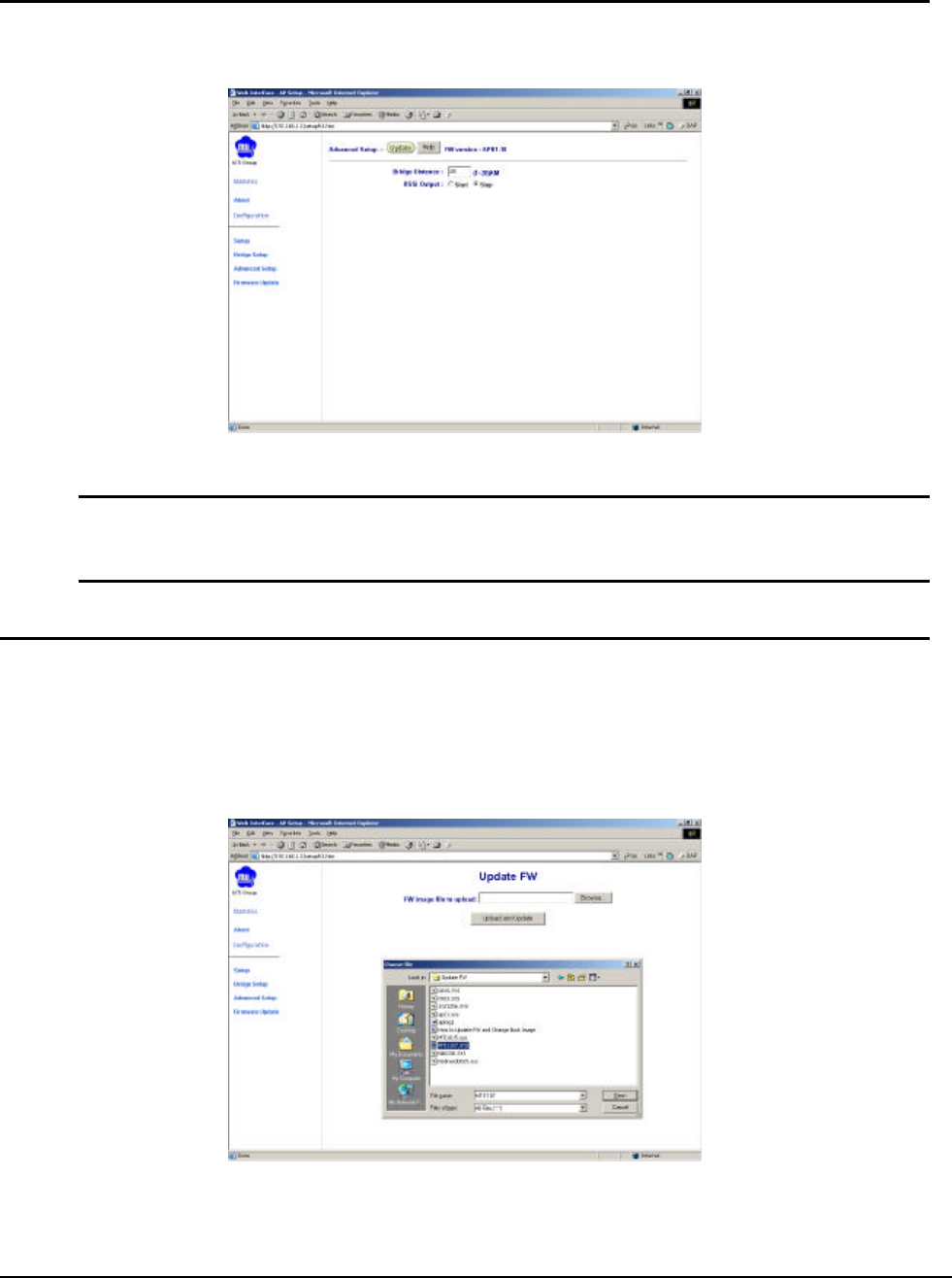
3-10 Advanced Setup Window
The Advanced Setup Window let you setup the distance between two bridges to make the
traffic more efficiency. See the following figure for Advance Setup Window.
Bridge System Advance Setup Window
NOTE: Select the distance between both bridges used in point to point connection.
It’s not necessary to select exact distance value in this input, but using a value bigger
than actual value is most important. A smaller value selected may cause link fail.
3-11 Firmware Update Configuration Window
The Firmware Update Basic Configuration window allows viewing of the FTP location of new
firmware. The default values for the Host Name, Image Path, and Image Name appear in the
window.
To access the Firmware Update window, click on Firmware Update in the navigation bar. The
Firmware Update Configuration Window appears (see Figure).
Bridge Firmware Update Configuration Window
Bridge uses the File Transfer Protocol (FTP) to download the Operating image from the HPC.
An FTP server utility is required to perform the data transfer between the Bridge and HPC.
802.11a Bridge AP5822 MTI Proprietary Page 28
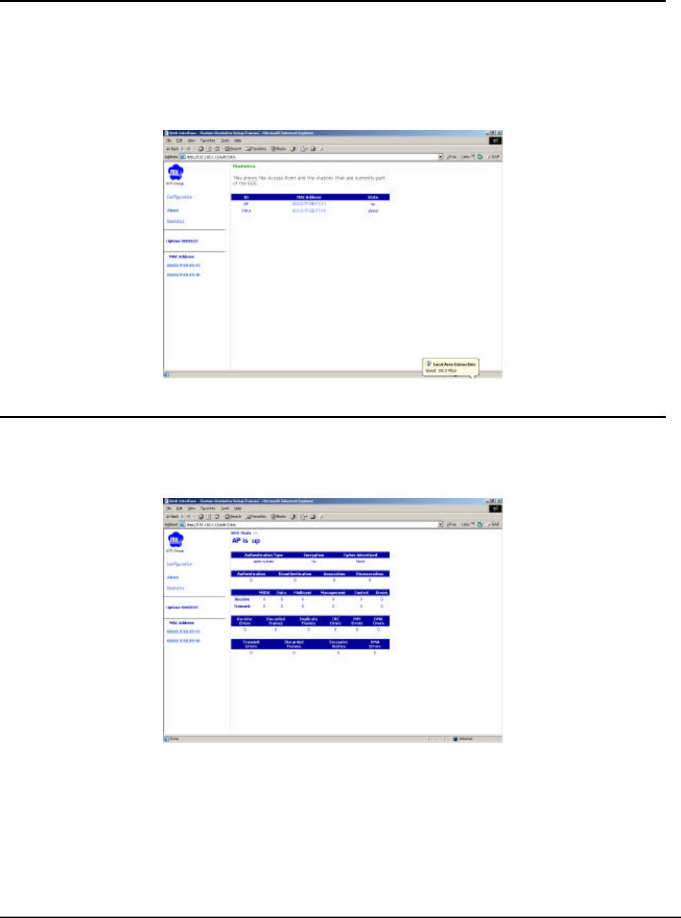
3-12 Statistics Windows
From the Bridge Web Server, choose the Statistics hyperlink to go to the Bridge Statistics
window. By default, this is the first window that appears once the Bridge Web Server opens.
The Bridge Statistics window allows viewing of the assigned ID, MAC address, and current
state of the Bridge and all stations currently part of its BBS (Basic Service Set). The top-level
Statistics window automatically updates each minute.
3-13 Bridge Statistics
To view statistics on the Bridge, click on the MAC address hyperlink for the desired Bridge in
the Statistics window. The BSS Stats window for the selected Bridge will appear. See Figure
for an example of a BSS Stats window for a Bridge.
Basic Service Set Statistics Window for an Bridge
The BSS Stats window for Bridge is divided into sections that provide the Bridge
configuration, Bridge SME statistics (station association information), or Bridge (Transmit and
Receive) Statistics. Refer to Table for a description of the BSS Statistics for Bridge window
fields.

802.11a Bridge AP5822 MTI Proprietary Page 29
Table. BSS Stats Field for Bridge Descriptions
BSS Stats Field Description
State Current state of the Bridge.
Authentication Type Specifies open-system or shared key.
Encryption Specifies the enabled state of encryption; either yes or no.
Cipher Advertised Specifies current state of advertised cipher
negotiations, AES and/or WEP, and
None (clear).
Authentication/Deauthentication
Number of times a STA attempted authentication and deauthentication.
Association/Deassociation Number of times a STA attempted associations and deassociations.
MSDU Maximum Service Data Unit. Specifies the number
of packets sent and received
by the Bridge.
Data/Management/Control Packets can either be data, control, or management.
Specifies the number of
packets sent and received for each.
Multicast Specifies the number of multicast packets both sent and received.
Errors Specifies the error count for both transmit and receive.
Receive Errors Specifies the number of receive errors.
Discarded Frames Specifies the number of receive discarded frames.
Duplicate Frames Specifies the number of receive duplicate frames.
CRC Errors Specifies the number of receive CRC errors.
PHY Errors Specifies the number of receive PHY errors.
DMA Errors Specifies the number of receive DMA errors.
Transmit Errors Specifies the number of transmit errors.
Discarded Frames Specifies the number of transmit discarded frames.
Excessive Retries Specifies the number of transmit excessive retries.
DMA Errors Specifies the number of transmit DMA errors.
The Bridge Stats window automatically updates every five seconds.
802.11a Bridge AP5822 MTI Proprietary Page 30
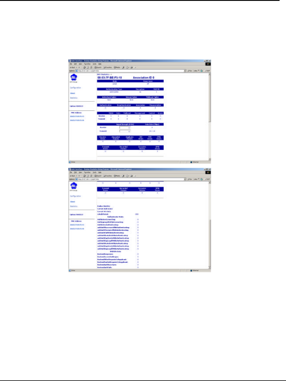
3-14 Station Statistics
To view statistics on any STA, click on the MAC address hyperlink for the desired STA. The
BSS Stats window for the selected STA will appear. See Figure for an example BSS Stats
window for a station.
The BSS Stats window for stations provides the station configuration and statistics for the
selected station. (See figure)
Table summarizes the information fields on the BSS Stats window for a STA.

802.11a Bridge AP5822 MTI Proprietary Page 31
Table. BSS Stats Fields for STA Descriptions
BSS Stats Window for STA Field Description
AID The ID of the STA.
State The current state of the STA
Power Save Specifies the enabled state of the power save option; either yes or no.
Encryption Specifies current state of encryption; AES and/or WEP, and None
(clear).
Advertised Cipher Specifies the supported cipher types.
Unicast Cipher Specifies the current unicast cipher type used.
Multicast Cipher Specifies the current multicast cipher type used.
Authentication/Deauthentication Number of times a STA attempted authentication and deauthentication.
Association/Deassociation Number of times a STA attempted associations and deassociations.
MSDU Maximum Service Data Unit. Specifies the number of packets sent and
received by the STA.
Data/Management/Control Packets can either be data, control, or management. Specifies the
number of packets sent and received for each.
Multicast Specifies the number of multicast frames.
Errors Specifies the error count for both transmit and receive sides.
Signal Strength Specifies the strength of the transmit and receive signals in dBm.
Data Rate (Mbps) Specifies the transmit and receive data rate in Mbps.
Receive Errors Specifies the number of receive errors.
Discarded Frames Specifies the number of receive discarded frames.
Duplicate Frames Specifies the number of receive duplicate frames.
CRC Errors Specifies the number of receive CRC errors.
PHY Errors Specifies the number of receive PHY errors.
DMA Errors Specifies the number of receive DMA errors.
Transmit Errors Specifies the number of transmit errors.
Discarded Frames Specifies the number of transmit discarded frames.
Excessive Retries Specifies the number of transmit excessive retries.
DMA Errors Specifies the number of transmit DMA errors.
802.11a Bridge AP5822 MTI Proprietary Page 32
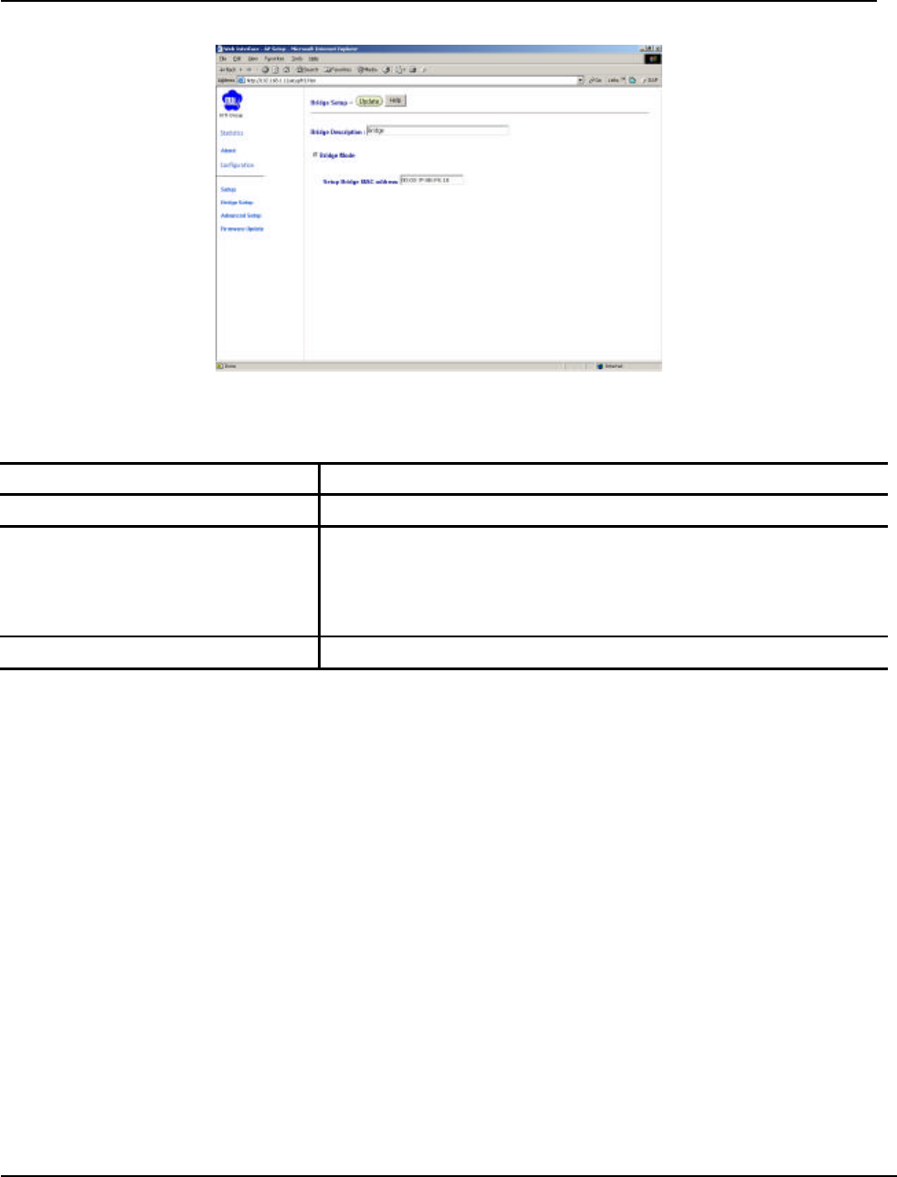
3-15 Bridge setup window
In this window, to input what the equipment it is. All the fields are described as following table:
Bridge window field Description
Bridge Description Enter your description for your bridge system
Operation Mode Select which mode the equipment used:
• AP Mode
• Bridge Mode (only this item active now)
• AP/Bridge Mode
Setup Bridge MAC address Enter the MAC address for bridge installed on the other side.

802.11a Bridge AP5822 MTI Proprietary Page 33
Appendix A Acronyms & Abbreviations
AC Alternating Current
ACL Access Control List
AES Advanced Encryption Standard
AID Access Identifier
AP Access Point
BBS Basic Service Set
CLI Command Line Interface
CRC Cyclic Redundancy Code
DC Direct Current
DMA Direct Memory Access
DNS Domain Name Server/Service
DOS Disk Operating System
ESD Electrostatic Discharge
EULA End User License Agreement
FCC Federal Communications
Commission
FTP File Transfer Protocol
GIF Graphic Interchange Format
HPC Host Personal Computer
ID Identification/Identity/Identifier
IEEE Institute of Electrical & Electronics
Engineers
JPG Joint Photographic Experts Group
LAN Local Area Network
MAC Media Access Control
MSDU Maximum Service Data Unit
ODU Outdoor Unit
PC Personal Computer
PHY Physical Layer
POE Power Over Ethernet
RADIUS
Remote Authentication Dial-In User
Server/Service
RSSI Received Signal Strength
Indication/Indicator
SNMP Simple Network Management
Protocol
SSID Service Set Identifier
STA station
TBD To Be Defined
TCP/IP
Transmission Control
Protocol/Internet Protocol
TV Television
VDC Volts Direct Current
WEP Wired Equivalent Privacy
VLAN Virtual Local Area Network