Microelectronics Technology RU-835 MINI ME II User Manual RU 814 DIGI Test Procedure
Microelectronics Technology Inc MINI ME II RU 814 DIGI Test Procedure
User Manual.pdf
MTI RFID ME User Manual
Version 1.6
July 9, 2014
MTI Group Proprietary Information
Any unauthorized use, duplication, reproduction, reverse engineering,
decompilation, or disclosure of this document may be considered as
infringement of MTI Group’s intellectual property rights, the infringer may
be accused and liable applicable legal penalties.
Copyright, Microelectronics Technology Inc.. All rights reserved.
Copyright, Microelectronics Technology Inc.. All right reserved.

MTI RFID ME User Manual
- 2 - Jul 9, 2014
Federal Communication Commission Interference Statement
This device complies with Part 15 of the FCC Rules. Operation is subject to the following two
conditions: (1) This device may not cause harmful interference, and (2) this device must accept any
interference received, including interference that may cause undesired operation.
This equipment has been tested and found to comply with the limits for a Class B digital device,
pursuant to Part 15 of the FCC Rules. These limits are designed to provide reasonable protection
against harmful interference in a residential installation. This equipment generates, uses and can
radiate radio frequency energy and, if not installed and used in accordance with the instructions, may
cause harmful interference to radio communications. However, there is no guarantee that
interference will not occur in a particular installation. If this equipment does cause harmful
interference to radio or television reception, which can be determined by turning the equipment off
and on, the user is encouraged to try to correct the interference by one of the following measures:
- Reorient or relocate the receiving antenna.
- Increase the separation between the equipment and receiver.
- Connect the equipment into an outlet on a circuit different from that
to which the receiver is connected.
- Consult the dealer or an experienced radio/TV technician for help.
FCC Caution: Any changes or modifications not expressly approved by the party responsible for
compliance could void the user's authority to operate this equipment.
This transmitter must not be co-located or operating in conjunction with any other antenna or
transmitter.

MTI RFID ME User Manual
- 3 - Jul 9, 2014
Radiation Exposure Statement:
The product comply with the FCC portable RF exposure limit set forth for an uncontrolled
environment and are safe for intended operation as described in this manual. The further RF exposure
reduction can be achieved if the product can be kept as far as possible from the user body or set the
device to lower output power if such function is available.
The USB dongle transmitter is approved for use in typical laptop computers. To comply with FCC
RF exposure requirements, it should not be used in other devices or certain laptop and tablet computer
configurations where the USB connectors on the host computer are unable to provide or ensure the
necessary operating configurations intended for the device and its users or bystanders to satisfy RF
exposure compliance requirements.

MTI RFID ME User Manual
- 4 - Jul 9, 2014
No part of this publication may be reproduced or used in any form, or by any electrical or mechanical
means, without permission in writing from Microelectronics Technology, Inc. This includes electronic
or mechanical means, such as photocopying, recording, or information storage and retrieval systems.
The material in this manual is subject to change without notice.
The software is provided strictly on an “as is” basis. All software, including firmware, furnished to the
user is on a licensed basis. Microelectronics Technology, Inc. grants to the user non-transferable and
non-exclusive license to use each software or firmware program delivered hereunder (licensed
program). Except as noted below, such license may not be assigned, sublicensed, or otherwise
transferred by the user without prior written consent of Microelectronics Technology, Inc. No right to
copy a licensed program in whole or in part is granted, except as permitted under copyright law. The
user shall not modify, merge, or incorporate any form or portion of a licensed program with other
program material, create a derivative work from a licensed program, or use a licensed program in a
network without written permission from Microelectronics Technology, Inc.
The user agrees to maintain Microelectronics Technology, Inc. copyright notice on the licensed
programs delivered hereunder, and to include the same on any authorized copies it makes, in whole or
in part. The user agrees not to decompile, disassemble, decode, or reverse engineer any hardware,
firmware or software (licensed program) delivered to the user or any portion thereof.
Microelectronics Technology, Inc. reserves the right to make changes to any software or product to
improve reliability, function, or design.
Microelectronics Technology, Inc. does not assume any product liability arising out of, or in
connection with, the application or use of any product, circuit, or application described herein.
No license is granted, either expressly or by implication, estoppel, or otherwise under any
Microelectronics Technology, Inc. intellectual property rights. An implied license only exists for
equipment, circuits, and subsystems contained in Microelectronics Technology, Inc. products.
MTI RFID ME User Manual
- 5 - Jul 9, 2014
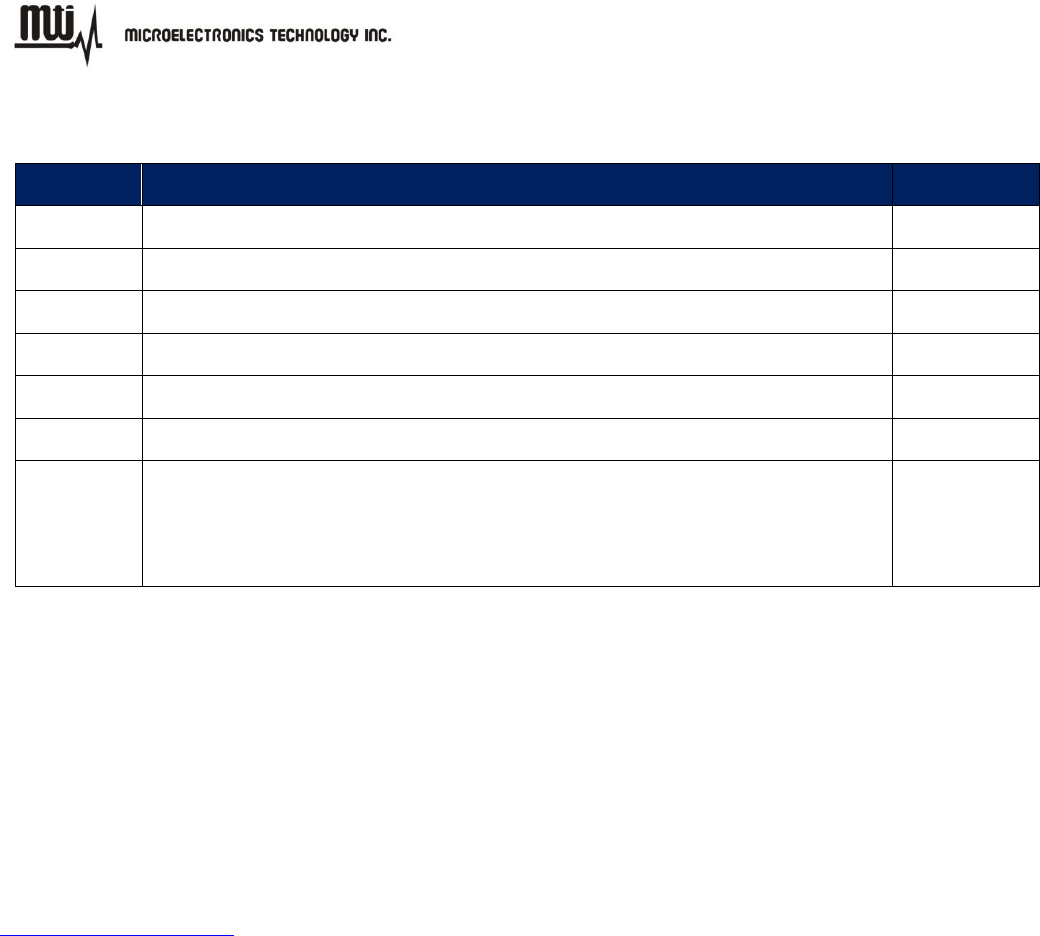
History
Version
Description
Time
1.0
Release
2010.12.08
1.1
Release
2011.04.21
1.2
Release
2011.12.09
1.3
Release
2011.12.23
1.4
Release
2011.12.30
1.5
Update
2012.04.26
1.6
1. Update figures to MTI RFID ME v1.0.20.
2. Add support RFID module section.
3. Modify and correct descriptions.
2014.06.09
Contact Information:
Microelectronics Technology, Inc.
No. 1 Innovation Road II,
Hsinchu Science Park,
Hsinchu 300, Taiwan, R.O.C.
http://www.mti.com.tw

MTI RFID ME User Manual
- 6 - Jul 9, 2014
Index
1. GETTING STARTED ............................................................................................................................................................... 7
1.1. INTRODUCTION .................................................................................................................................................................. 7
1.2. SUPPORT MODULE ........................................................................................................................................................... 7
1.3. CONTACT INFORMATION ................................................................................................................................................... 7
2. SETUP ....................................................................................................................................................................................... 8
2.1. SOFTWARE INSTALLATION ................................................................................................................................................ 8
2.2. START MTI RFID ME ..................................................................................................................................................... 12
3. READER SETTINGS ............................................................................................................................................................. 13
3.1. INTRODUCTION ................................................................................................................................................................ 13
3.2. ADVANCED READER SETTINGS ...................................................................................................................................... 15
4. INVENTORY RUN ................................................................................................................................................................. 20
5. TAG SETTINGS ..................................................................................................................................................................... 22
5.1. TAG SETTING FUNCTION ................................................................................................................................................. 24
5.2. MEMORY BANK ............................................................................................................................................................... 28
6. TROUBLESHOOTING/ FAQS ............................................................................................................................................. 30
6.1. INITIAL SETUP/ SOFTWARE ............................................................................................................................................. 30
6.2. READING TAGS ............................................................................................................................................................... 30
6.3. WRITING TAGS ................................................................................................................................................................ 30

MTI RFID ME User Manual
- 7 - Jul 9, 2014
1. Getting Started
1.1. Introduction
This manual provides you with the information needed to install and operate the MTI RFID ME. A
description on how to install the MTI RFID ME is provided in Section 2. Section 3, presents
information on how to configure the MTI RFID ME to read and write tags and discusses advanced
RFID configuration settings. Section 4 describes how to read tags (scanning and inventory runs).
Section 5 presents information on Advanced Tag Settings including changing EPC, Kill, Lock and
advanced feature settings.
1.2. Support Module
This user manual can be referred for below RFID reader modules.
Index
RFID Module
Index
RFID Module
1
RU-827
5
RU-888
2
RU-862
6
RU-835
3
RU-865
4
RU-865-P
1.3. Contact Information
Contact “rfid_support@mti.com.tw” for any questions regarding MTI RFID ME and hardware
support issues.
MTI RFID ME User Manual
- 8 - Jul 9, 2014
2. Setup
2.1. Software Installation
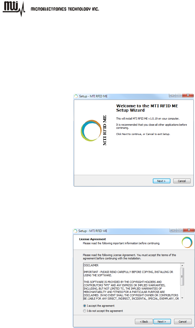
2.1.1. Double-click “MTI RFID ME.exe” in the installation disk, then click “Next” to continue the
installation, or click “Cancel” to exit the setup as shown in Figure 1.
Figure 1
2.1.2. Read the license agreement and select “I accept the agreement” as shown in Figure 2 to
accept.
Figure 2
MTI RFID ME User Manual
- 9 - Jul 9, 2014
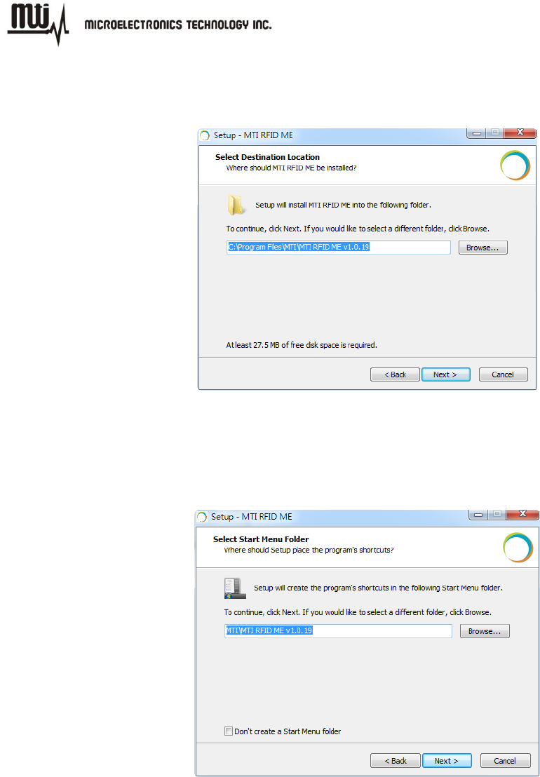
2.1.3. Select a Destination Folder. To select a different folder, click “Browse” and choose one of the
available options as shown in Figure 3.
Figure 3
2.1.4. Select a destination for the program’s shortcut. To select a different folder, click “Browse”
and choose one of the available options as shown in Figure 4.
Figure 4
MTI RFID ME User Manual
- 10 - Jul 9, 2014
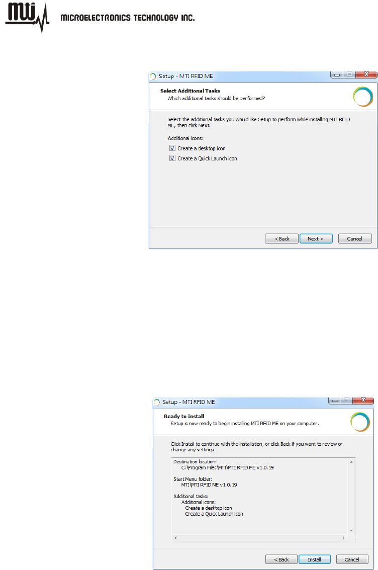
2.1.5. To add additional icons, “Check” desired boxes as shown in Figure 5.
Figure 5
“Checking” the ‘Create a desktop icon’ will generate an additional desktop icon;
“Checking” the ‘Create a Quick Launch icon’ will generate an Additional Quick Launch
icon located in the “Start” menu.
2.1.6. Press “Install” to begin software installation as shown in Figure 6.
Figure 6
MTI RFID ME User Manual
- 11 - Jul 9, 2014
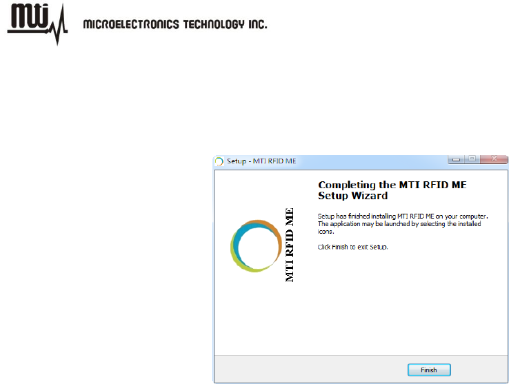
2.1.7. Congratulations! You have completed the MTI RFID ME software installation. Press “Finish”
to close the window. Select any of the installed icons to launch the MTI Reader Suite
program as shown in Figure 7.
Figure 7
2.1.8. For those whom running on Windows 7 platform, please do the setup as following:
1) Right click on the short cut of MTI RFID ME HW GUI in "Start" menu and select
"Properties".
2) Click on the tab "Compatibility" and select "Window XP Service Pack 3" in the pull down
menu of "Compatibility Mode".
MTI RFID ME User Manual
- 12 - Jul 9, 2014
2.2. Start MTI RFID ME
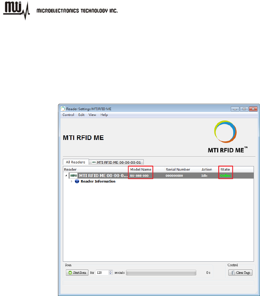
Insert RFID reader into the USB port, launch the installed MTI RFID ME, and make sure the
“State” column reads “Online” as shown in Figure 8.
The module name is described in the “Model Name” column as below.
Figure 8
MTI RFID ME User Manual
- 13 - Jul 9, 2014
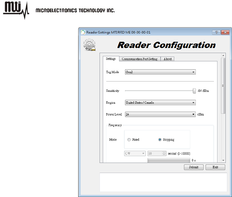
3. Reader Settings
3.1. Introduction
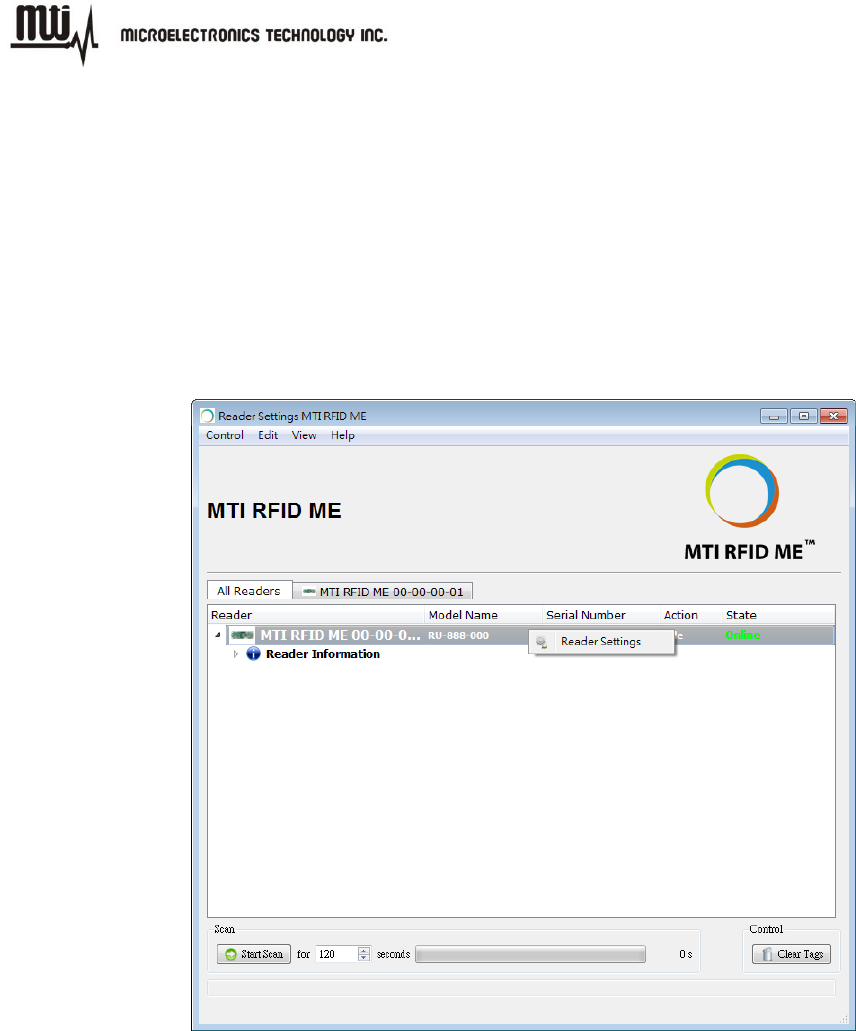
Right click the reader information that shows on the GUI of MTI RFID ME then click “Reader
Settings” to access the “Advanced Reader Settings” page. This page shows specific configuration
settings and information of the reader, including default and recommended settings as shown in
Figure 9 and Figure 10.
Figure 9
MTI RFID ME User Manual
- 14 - Jul 9, 2014
Figure 10
MTI RFID ME User Manual
- 15 - Jul 9, 2014
3.2. Advanced Reader Settings
3.2.1. Tag Mode: Gen2, Gen2+ RSSI
Gen2:ISO 18000-6C Tag
Gen2 + RSSI:ISO 18000-6C Tag and provides the Received Signal Strength
Indication (RSSI), channel Q, and channel I- path readings
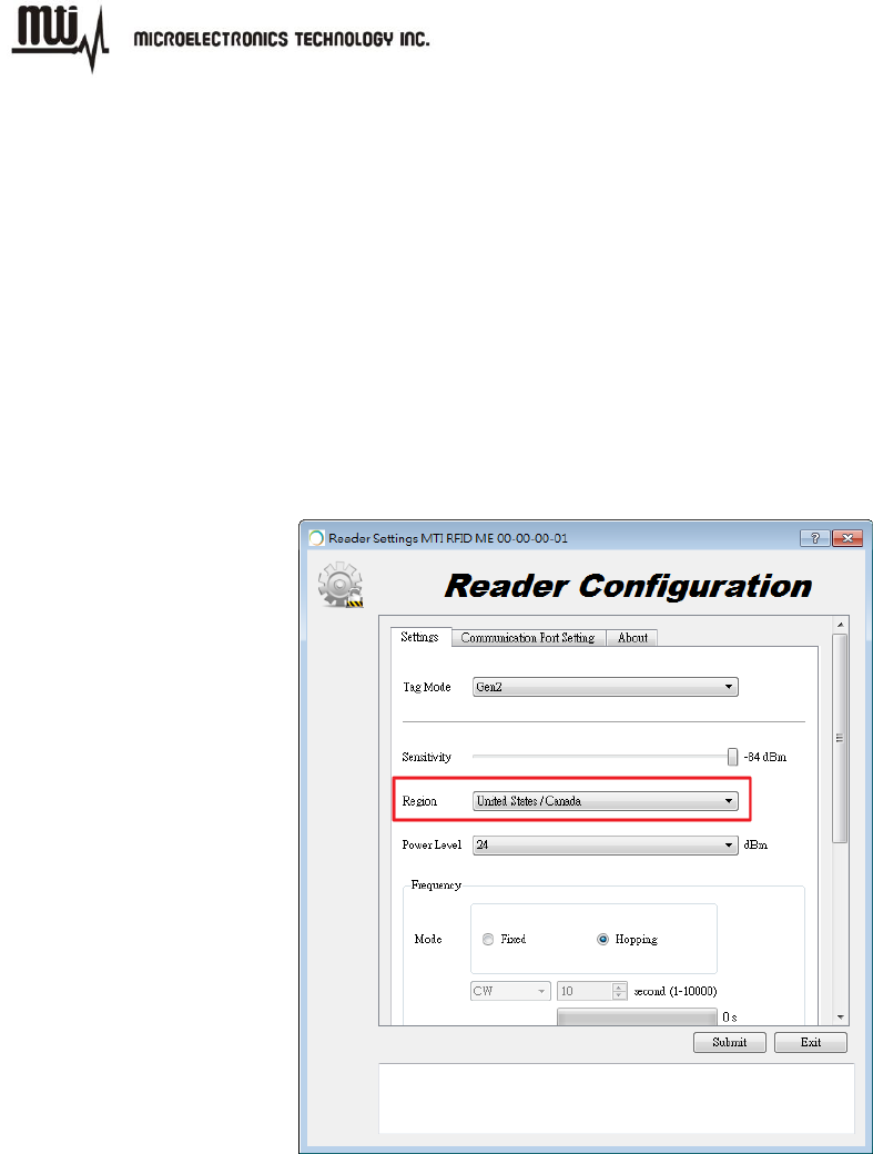
3.2.2. Region Settings
MTI RFID ME program can sense and detect the correct region of RFID reader.
Figure 11
FOR COUNTRY CODE SELECTION USAGE
Note: The country code selection is for non-US model only and is not available to all US
model. Per FCC regulation, all WiFi product marketed in US must fixed to US operation
channels only.
MTI RFID ME User Manual
- 16 - Jul 9, 2014
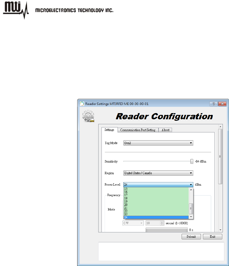
3.2.3. Transmit Power Level
To achieve the longest reading or writing range, set the power to the maximum
allowable level of +24dBm as shown in Figure 12.
To reduce the reading or writing range and minimize energy consumption, set the
power to the minimum allowable level of +10 dBm.
Figure 12
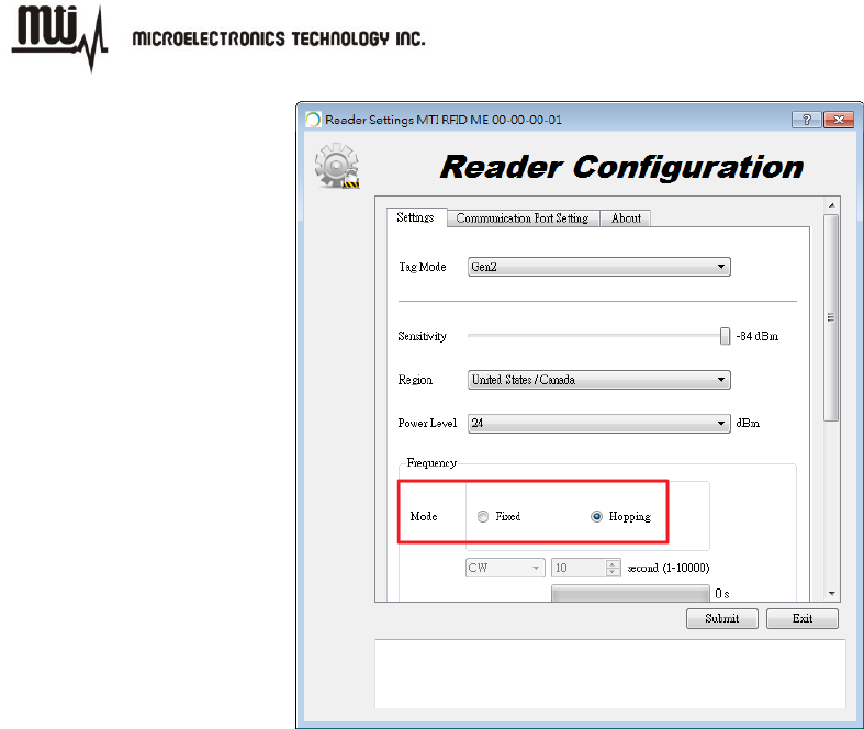
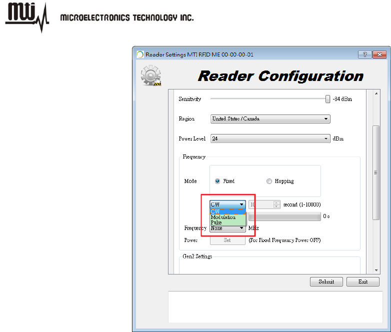
3.2.4. Frequency Setting
Hopping mode:Select frequency mode to “Hopping” to perform inventory scanning in
general.
MTI RFID ME User Manual
- 17 - Jul 9, 2014
Figure 13
Fixed mode:Select frequency mode to “Fixed” to perform test and evaluation in
general.
CW/Modulation/Pulse:These three settings only can be set when frequency mode is
set to “Fixed”. The settings used for engineering evaluation.
CW:To test output power linearity at the assigned frequency.
Modulation:To test the spectrum mask at the assigned frequency.
Pulse:To test ETSI standard 302 208 v1.3.1.
MTI RFID ME User Manual
- 18 - Jul 9, 2014
Figure 14
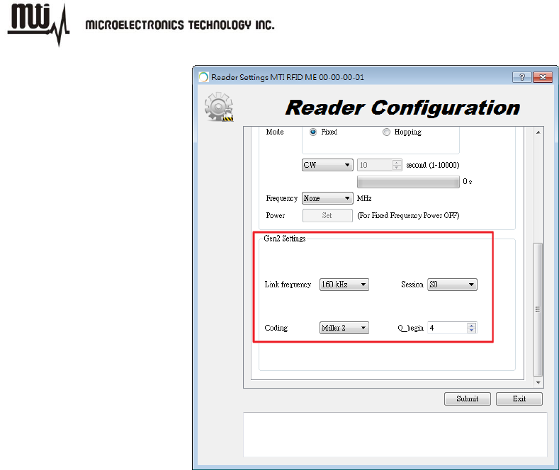
3.2.5. Gen2 Setting
Figure 15 illustrates how to change or modify the Gen2 profile of the MTI RFID ME and EPC tag.
For more details regarding definitions Gen2 settings, parameters and limits please reference the
Class 1 Generation 2 UHF Air Interface Protocol Standard “Gen 2”
(http://www.epcglobalinc.org/standards/uhfc1g2)
MTI RFID ME HW GUI Default Settings
Link frequency:160KHz
Session:S0
Coding:Miller 2
Q_begin:4
MTI RFID ME User Manual
- 19 - Jul 9, 2014
Figure 15
MTI RFID ME User Manual
- 20 - Jul 9, 2014
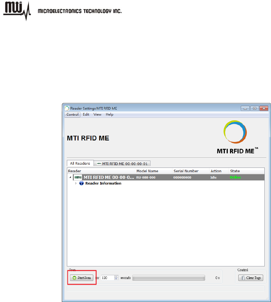
4. Inventory Run
After configuring the MTI RFID ME settings as described in section 3, you are ready to start an
inventory run. Click the “Start Scan” button located in the lower left corner of the window as
shown in Figure 16.
Figure 16
MTI RFID ME User Manual
- 21 - Jul 9, 2014
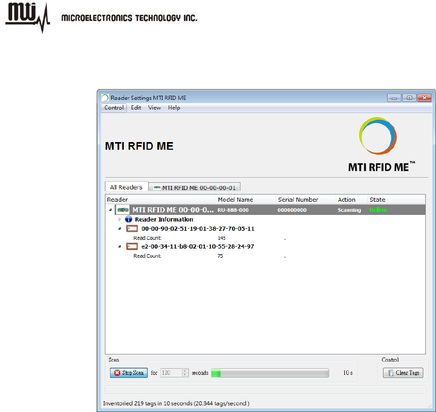
Figure 17 shows an example of a “Start Scan” operation and where the MTI RFID ME is reading
two tags.
Figure 17
MTI RFID ME User Manual
- 22 - Jul 9, 2014
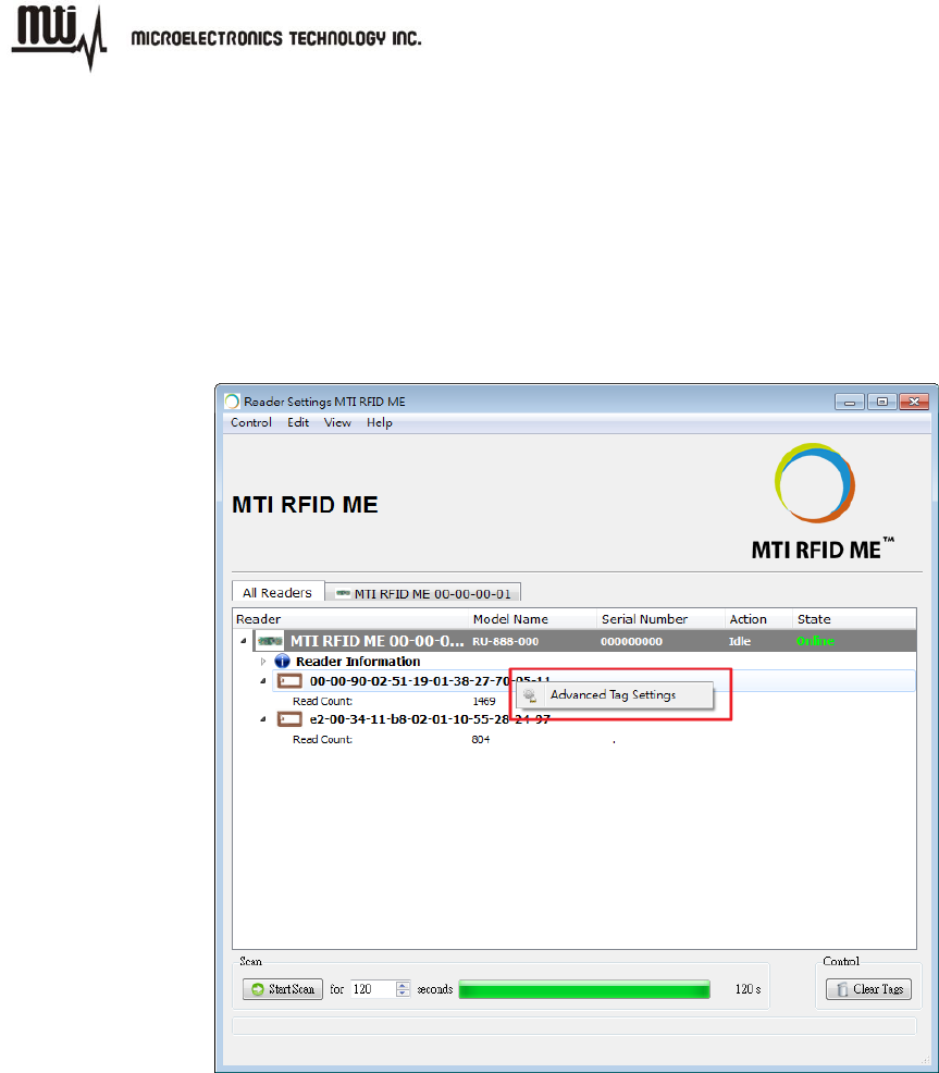
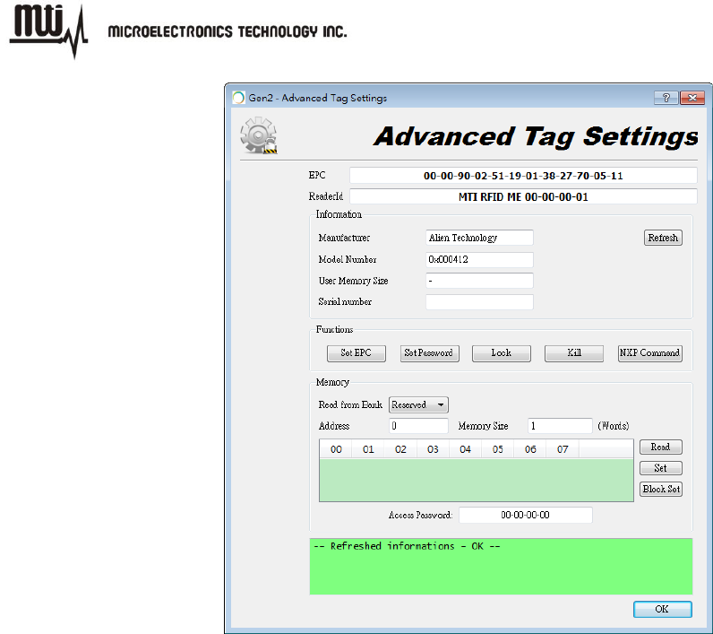
5. Tag Settings
Please stop scan before configure tag. Right click on the EPC of the tag that want to modify then
click the “Advanced Tag Settings” as shown in Figure 18. User can configure tag in “Advanced
Tag Settings” page as shown in Figure 19.
Figure 18
MTI RFID ME User Manual
- 23 - Jul 9, 2014
Figure 19
MTI RFID ME User Manual
- 24 - Jul 9, 2014
5.1. Tag Setting Function
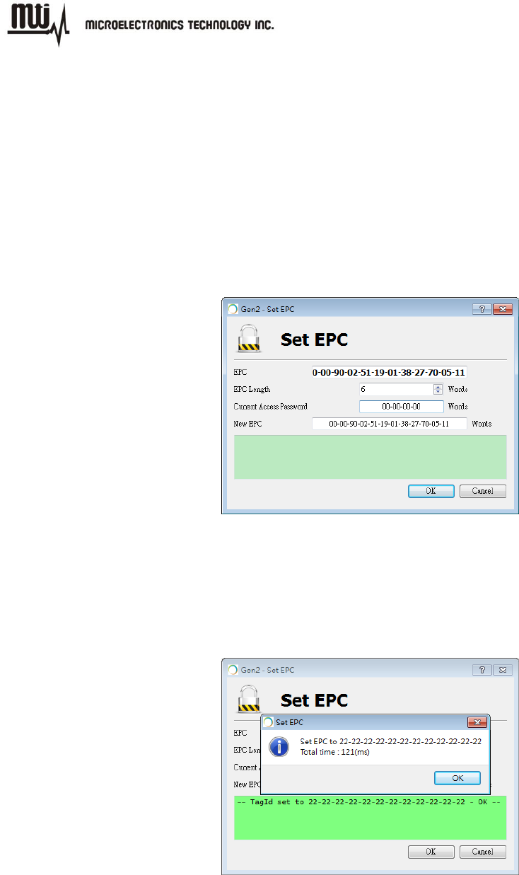
5.1.1. Set EPC
Click “Set EPC” button then enter setting window to modify or change a tag’s EPC. The EPC,
EPC length and access password can be set in this window.
Note: The default setting for the “Current Access Password” is 00-00-00-00. For any other
“Current Access Password” settings other then 00-00-00-00, please refer to Class 1 Generation 2
UHF Air Interface Protocol Standard “Gen 2” at http://www.epcglobalinc.org/standards/uhfc1g2.
Figure 20
EPC Write Successful
MTI RFID ME will alert a confirmation message to show the EPC information is set
successfully.
Figure 21
MTI RFID ME User Manual
- 25 - Jul 9, 2014
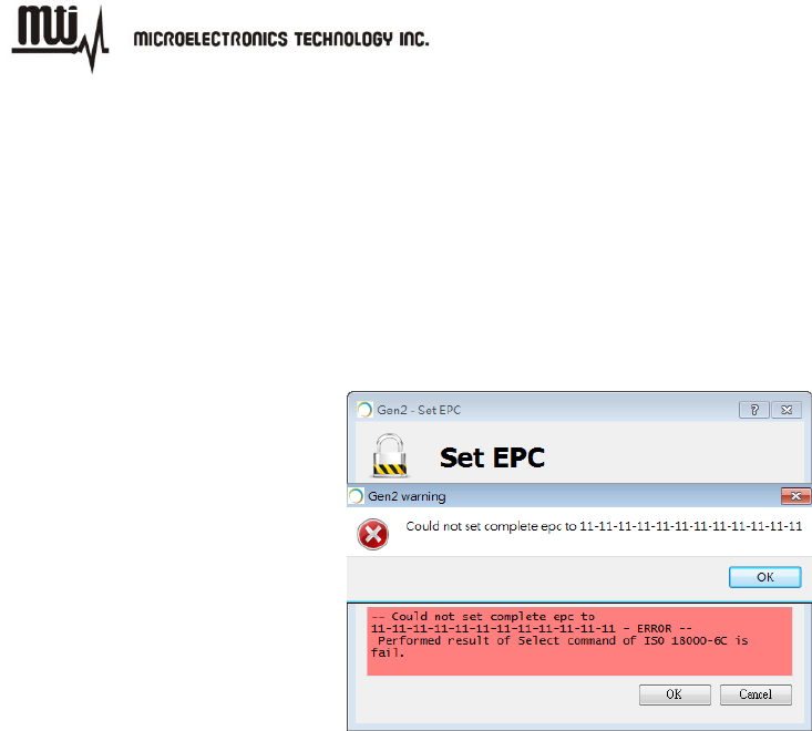
EPC Write Failed
MTI RFID ME will alert a confirmation message to show the EPC information is
set unsuccessfully. Repeat the EPC setting process maybe can resolve write
failed problem due to RF status is not stable.
Note: It may get some improvement to change position of the tag or increase/
decrease power level.
Figure 22
MTI RFID ME User Manual
- 26 - Jul 9, 2014
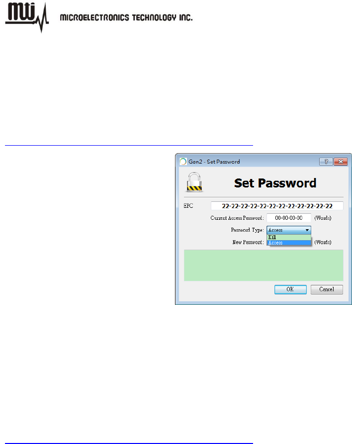
5.1.2. Set Password
Click “Set Password” button then enter setting window to change the password of tag. The default
“Current Access Password” is 00-00-00-00. For more detailed information regarding password
settings please refer to the Class 1 Generation 2 UHF Air Interface Protocol Standard “Gen 2” at
http://www.epcglobalinc.org/standards/uhfc1g2
Figure 23
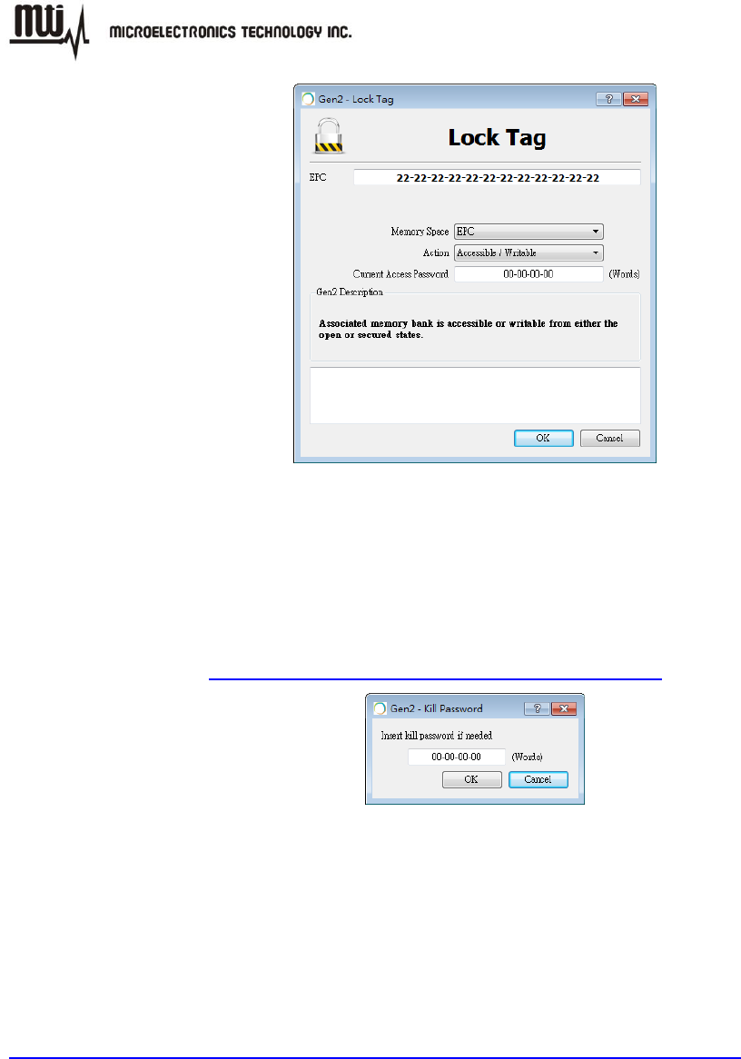
5.1.3. Lock
Click “Lock” button then enter setting window to change access/write authority of the specific
memory bank. For more information regarding lock and associated memory banks please refer to
Class 1 Generation 2 UHF Air Interface Protocol Standard “Gen 2” at
http://www.epcglobalinc.org/standards/uhfc1g2
MTI RFID ME User Manual
- 27 - Jul 9, 2014
Figure 24
5.1.4. Kill
Click “Kill” button then enter setting window to kill a tag with kill password. For more information
about kill and kill password please refer to Class 1 Generation 2 UHF Air Interface Protocol
Standard “Gen 2” at http://www.epcglobalinc.org/standards/uhfc1g2
Figure 25
5.1.5. NXP Command
Click “NXP Command” button then enter setting window to execute command for NXP tag.
Moreover, “Configuration” must be set if select “ChangeConfig 09-00”. For more information
about NXP command, please refer to SL3ICS1002/1202 UCODE G2xM and G2XL at
http://www.nxp.com/documents/data_sheet/SL3ICS1002_1202_139036.pdf
NXP Command
Set Read Protect 02-01: Enable reliable read protection of the entire G2X memory.
Unset Read Protect 02-00: Reset the ReadProtect-bit and re-enables reading of the
G2X memory content according the EPCglobal specification.
Change EAS ON 01-01: An EAS-Alarm bit set to ‘1’ the tag will reply to an
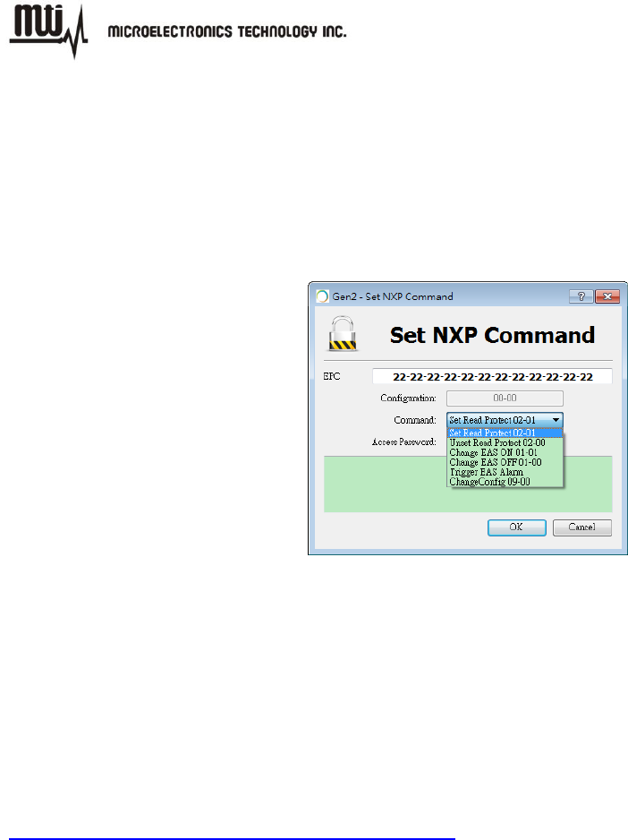
MTI RFID ME User Manual
- 28 - Jul 9, 2014
EAS_Alarm command by backscattering a 64 bit alarm code.
Change EAS OFF 01-00: An EAS-Alarm bit set to ‘0’ the tag will not reply to an
EAS_Alarm command by backscattering a 64 bit alarm code.
Trigger EAS Alarm: Reply an EAS_Alarm command by backscattering a 64 bit alarm
code without the need of a Select or Query.
ChangeConfig 09-00: Configures the additional features of the tag like Read-Protect,
EAS Alarm etc.
Figure 26
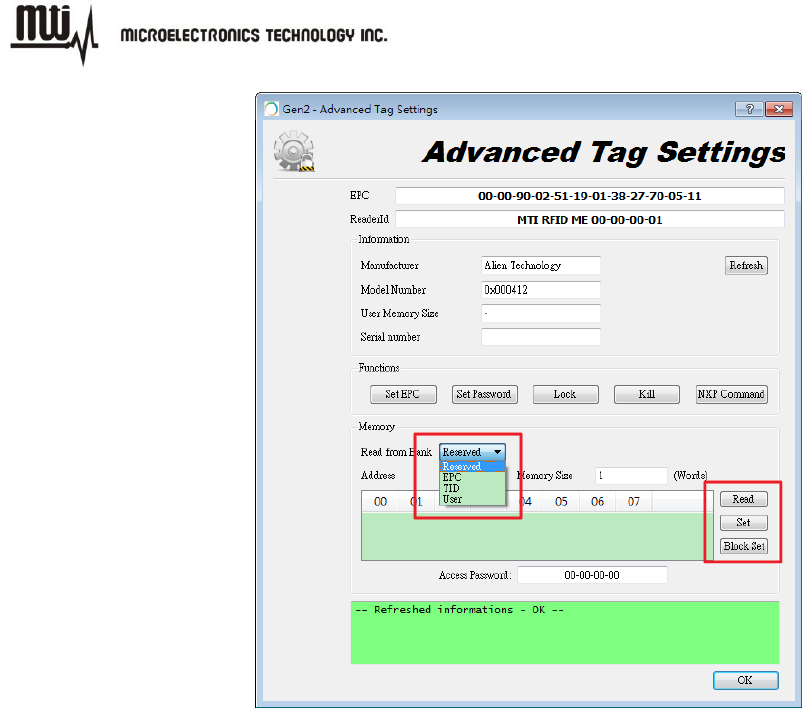
5.2. Memory Bank
There are four memory banks can be operated that are “Reserved”, “EPC”, “TID” and “User” in
MTI RFID ME. User can read/ write a specified memory block by click “Read”, “Set” and “Block
Set”. For more information about how to configure memory bank for your use case, please refer
to Class 1 Generation 2 UHF Air Interface Protocol Standard “Gen 2” at
http://www.epcglobalinc.org/standards/uhfc1g2
MTI RFID ME User Manual
- 29 - Jul 9, 2014
Figure 27
MTI RFID ME User Manual
- 30 - Jul 9, 2014
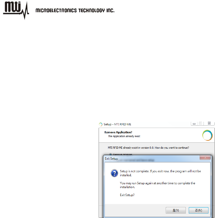
6. Troubleshooting/ FAQs
6.1. Initial Setup/ Software
If the software fails to install as shown in Figure 28, repeat the installation process over again,
first uninstall the prior MTI RFID ME installation, and then re-install again using the same steps
listed in section 2.1.
Figure 28
6.2. Reading Tags
If reader is “Offline” and does not identify tags, make sure the state/status of the MTI RFID ME is
“Online” reference Figure 9 which shows “Online” status).
In general, reading tags depends on a lot of different conditions, please verify that there are no
metal or liquid objects surrounding the RFID reader and/or near the tags (such as a metal table,
or glass of water).
6.3. Writing Tags
If tag status displays “ERROR”, make sure the tag and reader proximity is very close (touching if
necessary), and try again.