Microelectronics Technology WA8011-A A8 802.11a/b/g AP BS/Bridge AC User Manual Manual 1
Microelectronics Technology Inc A8 802.11a/b/g AP BS/Bridge AC Manual 1
UserManual.wiki
>
Microelectronics Technology
>
WA8011-A User Manual
>
Manual 1
Contents
1.
Manual 1
2.
Manual 2
Manual 1
Navigation menu
Upload a User Manual
Namespaces
Wiki Guide
HTML
PDF
Info
Views
User Manual
Discussion / Help
Navigation
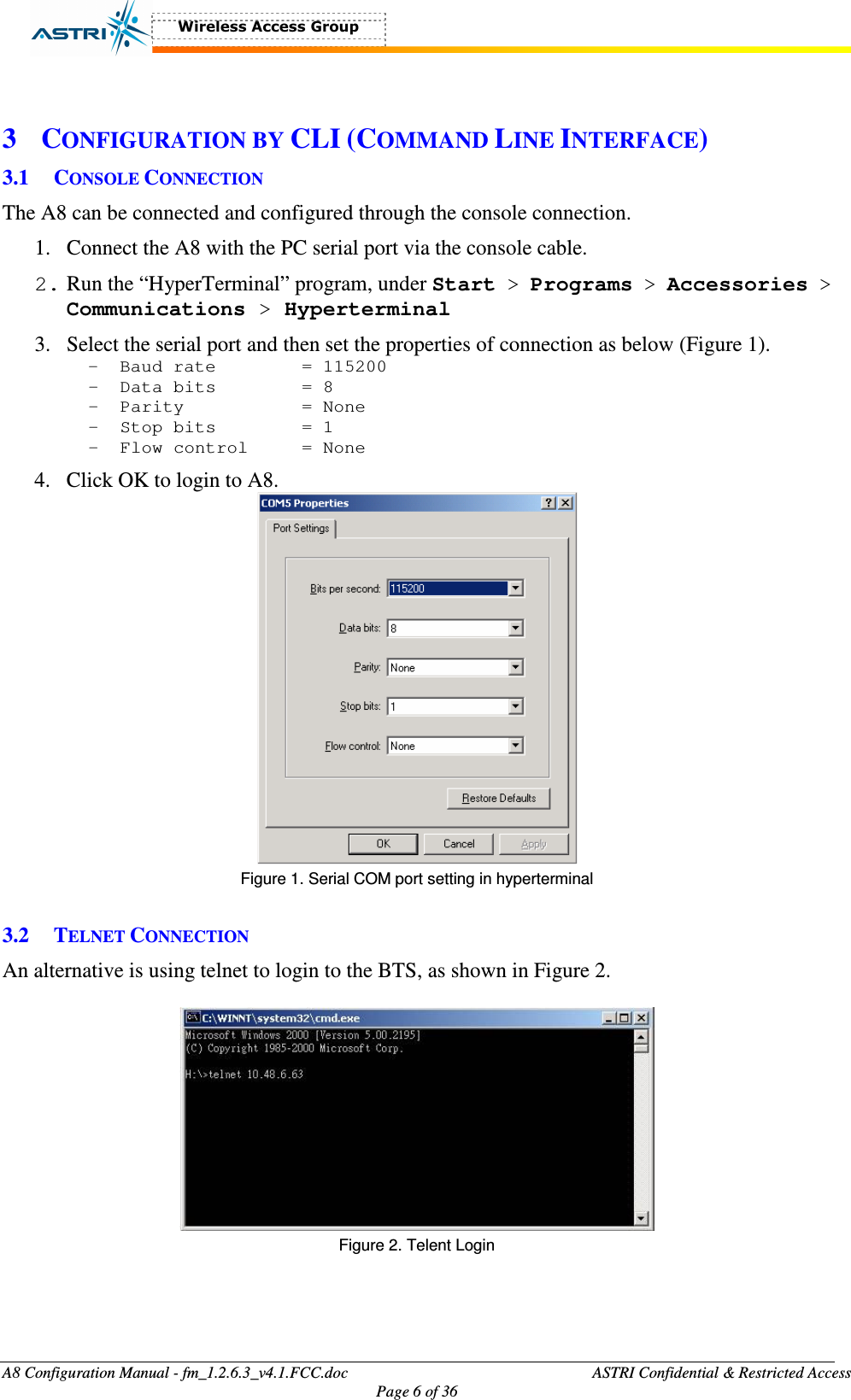
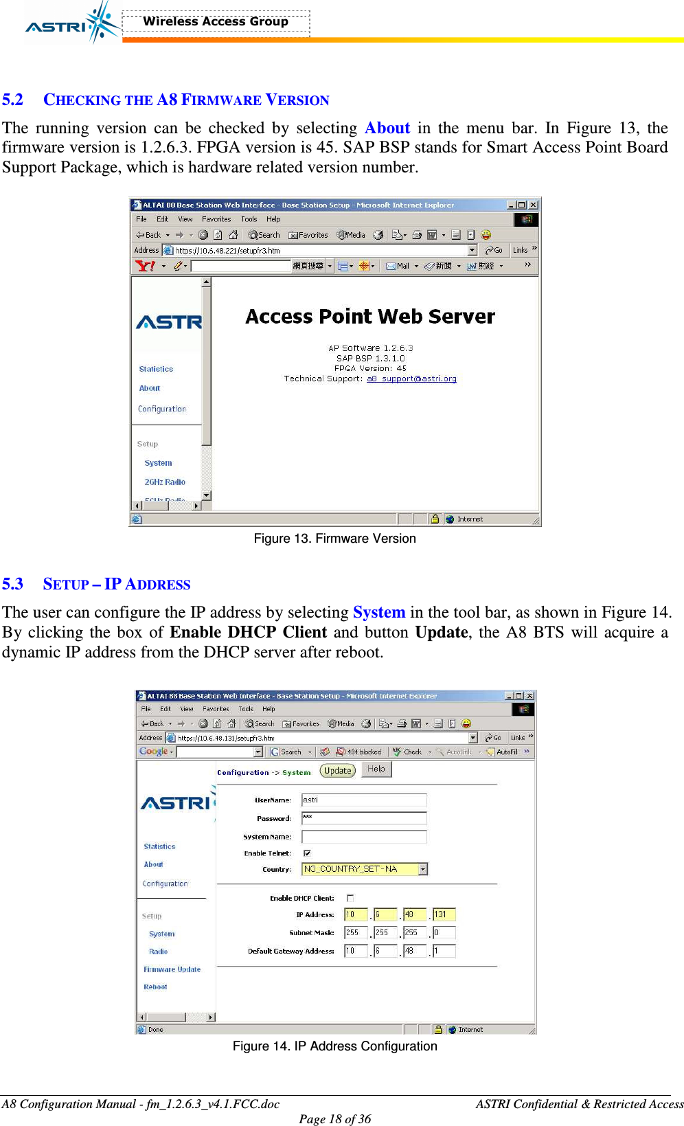
![A8 Configuration Manual - fm_1.2.6.3_v4.1.FCC.doc ASTRI Confidential & Restricted Access Page 1 of 36 A8 Configuration Professional Manual Version 4.1 (03-Apr-2006/HKT) Document Control Draft/ Version Date Author Reviewer Change / Comments Draft 15-Jun-05 Maurice Chan First Draft 1.1 17-Oct-05 Maurice Chan Updated [A8R0 v0.3.0.13] 2.0 19-Oct-05 Maurice Chan For A8R1 v1.1.1.9 3.0 19-Dec-05 Maurice Chan For A8 R2 v1.2.0.5 3.1 07-Feb-06 Maurice Chan For A8 R2 v1.2.4.2 with web-admin 3.2 07-Feb-06 Maurice Chan For A8 R2 v1.2.5.1 3.3 09-Feb-06 Maurice Chan Add FCC statements 3.4 15-Feb-06 Maurice Chan Add encryption in web-admin 3.5 28-Feb-06 Maurice Chan Add a warning statement 3.6 17-Mar-06 Maurice Chan Add model name and no. for FCC 4.0 24-Mar-06 Maurice Chan Add web-admin for 802.11a 4.1 03-Apr-06 Maurice Chan Add details for FCC](https://usermanual.wiki/Microelectronics-Technology/WA8011-A.Manual-1/User-Guide-645917-Page-1.png)