Microelectronics Technology WA8011-A A8 802.11a/b/g AP BS/Bridge AC User Manual Manual 1
Microelectronics Technology Inc A8 802.11a/b/g AP BS/Bridge AC Manual 1
Contents
- 1. Manual 1
- 2. Manual 2
Manual 1

A8 Configuration Manual - fm_1.2.6.3_v4.1.FCC.doc ASTRI Confidential & Restricted Access
Page 1 of 36
A8 Configuration
Professional Manual
Version 4.1
(03-Apr-2006/HKT)
Document Control
Draft/
Version
Date Author Reviewer Change / Comments
Draft 15-Jun-05 Maurice Chan First Draft
1.1 17-Oct-05 Maurice Chan Updated
[A8R0 v0.3.0.13]
2.0 19-Oct-05 Maurice Chan For A8R1 v1.1.1.9
3.0 19-Dec-05 Maurice Chan For A8 R2 v1.2.0.5
3.1 07-Feb-06 Maurice Chan For A8 R2 v1.2.4.2
with web-admin
3.2 07-Feb-06 Maurice Chan For A8 R2 v1.2.5.1
3.3 09-Feb-06 Maurice Chan Add FCC statements
3.4 15-Feb-06 Maurice Chan Add encryption in web-admin
3.5 28-Feb-06 Maurice Chan Add a warning statement
3.6 17-Mar-06 Maurice Chan Add model name and no. for FCC
4.0 24-Mar-06 Maurice Chan Add web-admin for 802.11a
4.1 03-Apr-06 Maurice Chan Add details for FCC

A8 Configuration Manual - fm_1.2.6.3_v4.1.FCC.doc ASTRI Confidential & Restricted Access
Page 2 of 36
Copyright © 2004 – 2006 Applied Science and Technology Research Institute Limited
ALL RIGHTS RESERVED.
Wireless Access Group
Applied Science and Technology Research Institute Company Limited
5th Floor, Photonics Centre,
2 Science Park East Avenue,
Hong Kong Science Park,
Shatin, New Territories,
Hong Kong
Telephone: +852 3406 2800
Fax: +852 3406 2801
Web: www.astri.org
Customer Support Centre
Email: wa-support@astri.org
Telephone: +852 3406 2822

A8 Configuration Manual - fm_1.2.6.3_v4.1.FCC.doc ASTRI Confidential & Restricted Access
Page 3 of 36
Radio Frequency Interference Requirements
This device complies with Part 15 of FCC Rules.
Operation is subject to the following conditions:
1. This device may not cause harmful interference.
2. This device must accept any interference received, including interference that may cause
undesired operation.
3. This device should not be co-located or operating in conjunction with any other antenna or
transmitter.
Interference Statement
This equipment has been tested and found to comply with the limits for a Class B digital device,
pursuant to Part 15 of the FCC Rules, These limits are designed to provide reasonable protection
against harmful interference in a residential installation. This equipment generates, uses and can
radiate radio frequency energy and, if not installed and used in accordance with the instructions,
may cause harmful interference to radio communications.
However, there is no guarantee that interference will not occur in a particular installation. If this
equipment does cause harmful interference to radio or television reception, which can be
determined by turning the equipment off and on, the user is encouraged to try to correct the
interference by one of the following measures:
- Reorient or relocate the receiving antenna.
- Increase the separation between the equipment and receiver.
- Connect the equipment into an outlet on a circuit different from that to which the
receiver is connected.
- Consult the dealer or an experienced radio/TV technician for help.
FCC Caution: To assure continued compliance, (example – use only shielded interface cables when
connecting to computer or peripheral devices). Any changes or modifications not expressly
approved by the party responsible for compliance could void the user’s authority to operate this
equipment.
Warning
The user must keep apart from the base-station and antenna with at least 45cm when the
base-station is in operation.

A8 Configuration Manual - fm_1.2.6.3_v4.1.FCC.doc ASTRI Confidential & Restricted Access
Page 4 of 36
Table of Content
1
I
NTRODUCTION
.........................................................................................................................................5
2
A8
M
ODEL AND
F
IRMWARE
V
ERSION
......................................................................................................5
3
C
ONFIGURATION BY
CLI
(C
OMMAND
L
INE
I
NTERFACE
) .........................................................................6
3.1 Console Connection ................................................................................................... 6
3.2 Telnet Connection ...................................................................................................... 6
3.3 User Login.................................................................................................................. 7
3.4 Basic Configuration.................................................................................................... 7
3.5 Network configuration ............................................................................................... 8
3.6 Radio configuration.................................................................................................... 9
3.7 Advanced Configuration .......................................................................................... 10
3.8 802.11a Bridge ......................................................................................................... 12
3.9 Restore Configuratoin to Default Setting................................................................. 14
4
S
OFTWARE
U
PGRADE VIA THE
CLI.........................................................................................................15
4.1 Firmware Upgrade.................................................................................................... 15
4.2 FPGA Upgrade......................................................................................................... 16
5
C
ONFIGURATION BY
W
EB
-A
DMIN
..........................................................................................................17
5.1 IE Connection........................................................................................................... 17
5.2 Checking the A8 Firmware Version......................................................................... 18
5.3 Setup – IP Address ................................................................................................... 18
5.4 Setup – Radio Parameter.......................................................................................... 19
5.5 802.11a Setting in Web-admin................................................................................. 23
5.6 Default Setting in Web-Admin ................................................................................ 24
5.7 Reboot ...................................................................................................................... 24
6
P
ERFORMANCE
M
ANAGEMENT
M
ONITORING
W
EB
-A
DMIN
...................................................................25
6.1 Statistics ................................................................................................................... 25
7
S
OFTWARE
U
PGRADE BY
W
EB
-A
DMIN
...................................................................................................27
7.1 Firmware Update...................................................................................................... 27
8
B
OOT FROM A
FTP
S
ERVER
....................................................................................................................29
8.1 Boot from network ................................................................................................... 29
8.2 Boot from local flash device .................................................................................... 31
9
A8
R
ECOVERY
.........................................................................................................................................32
9.1 Boot-up from BootROM .......................................................................................... 32
10
C
ONFIGURE A USER ACCOUNT IN THE
FTP
S
ERVER
...............................................................................33
11
A
NTENNA
U
SAGE AND
T
RANSMIT
P
OWER
.............................................................................................35
12
A
PPENDIX
–
D
EFAULT
S
ETTING
..............................................................................................................36

A8 Configuration Manual - fm_1.2.6.3_v4.1.FCC.doc ASTRI Confidential & Restricted Access
Page 5 of 36
1 I
NTRODUCTION
This manual is to summarize how to perform basic configuration for the ASTRI A8 through
console connection and web-admin.
2 A8
M
ODEL AND
F
IRMWARE
V
ERSION
This manual is applicable for the following models, hardware and firmware version:
Product name : A8 802.11ab/g AP BS/Bridge AC
Model number : WA8011A-A
Product name : A8 802.11b/g AP BS AC
Model number : WA8011A-B
Hardware Platform Firmware Version Remark
R1 1.1.1.9 N/A
R2 1.2.0.5
1.2.4.2
1.2.5.1
1.2.5.4
1.2.6.3
N/A
Web-admin for 802.11b/g
N/A
N/A
Web-admin for 802.11a
A8 Configuration Manual - fm_1.2.6.3_v4.1.FCC.doc ASTRI Confidential & Restricted Access
Page 6 of 36
3 C
ONFIGURATION BY
CLI
(C
OMMAND
L
INE
I
NTERFACE
)
3.1 C
ONSOLE
C
ONNECTION
The A8 can be connected and configured through the console connection.
1. Connect the A8 with the PC serial port via the console cable.
2. Run the “HyperTerminal” program, under Start > Programs > Accessories >
Communications > Hyperterminal
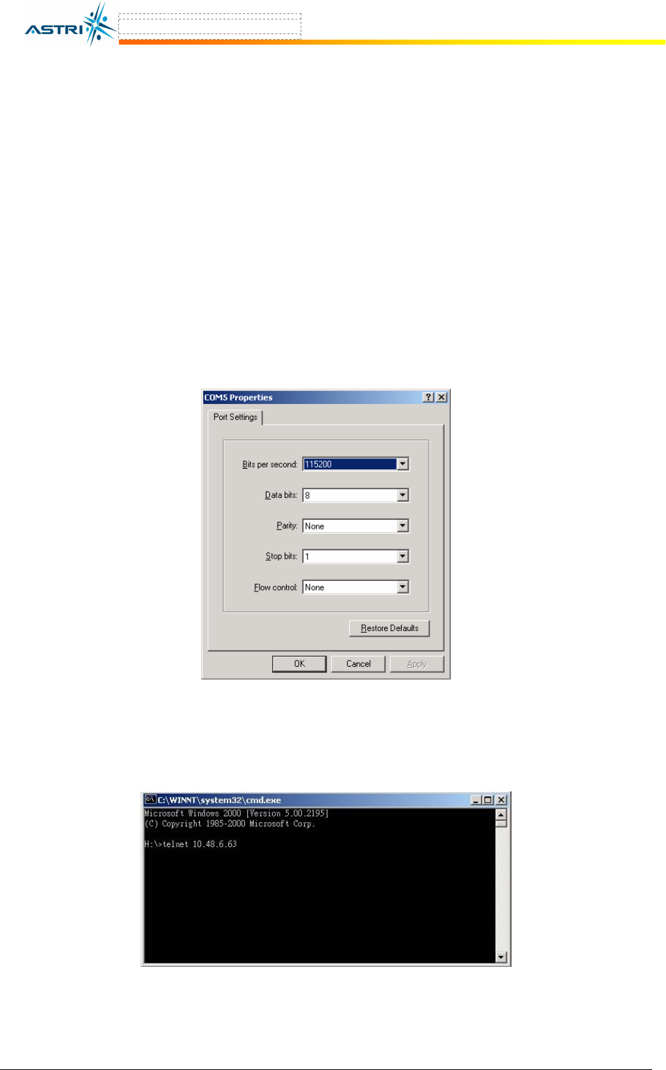
3. Select the serial port and then set the properties of connection as below (Figure 1).
- Baud rate = 115200
- Data bits = 8
- Parity = None
- Stop bits = 1
- Flow control = None
4. Click OK to login to A8.
Figure 1. Serial COM port setting in hyperterminal
3.2 T
ELNET
C
ONNECTION
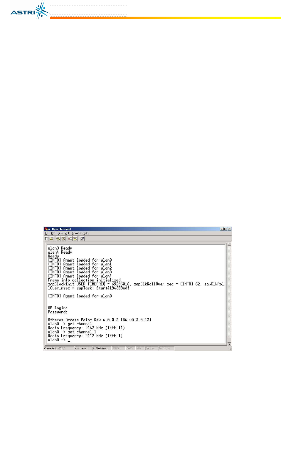
An alternative is using telnet to login to the BTS, as shown in Figure 2.
Figure 2. Telent Login
A8 Configuration Manual - fm_1.2.6.3_v4.1.FCC.doc ASTRI Confidential & Restricted Access
Page 7 of 36
3.3 U
SER
L
OGIN
After connecting to the A8, the user needs to enter a user name and password to login. Please
contact astri for the details if required.
You could change the login name and password in web-admin, as shown in Section 5.1.
The login name and password could be reset to the default settings in CLI (in Section 3.9) or in
BootRom (in Section 9.1).
3.4 B
ASIC
C
ONFIGURATION
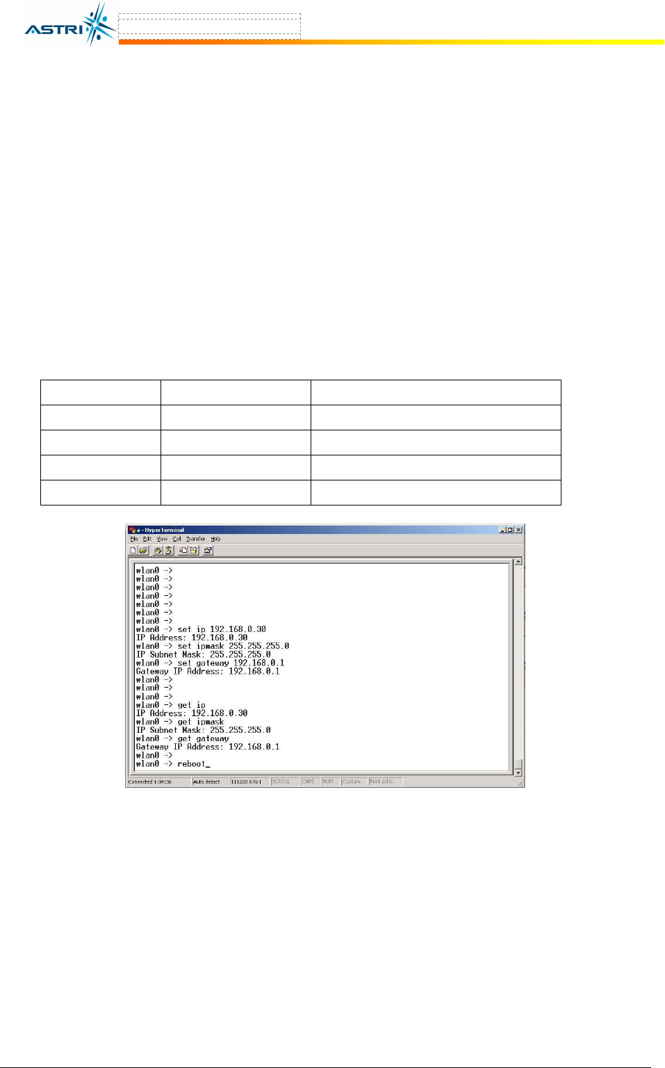
The channel frequency, TX power, ACL can be configured through command line interface
(CLI).
There are two basic commands:
1. GET : This command is used to retrieve the settings or parameters in A8.
Example : get channel
The above command is to retrieve the current channel configured in A8.
2. SET : This command is used to configure the A8.
Example : set channel 1
The above command is to configure the A8 to operate at Channel 1.
An example is shown in Figure 3.
Figure 3. An example in CLI
A8 Configuration Manual - fm_1.2.6.3_v4.1.FCC.doc ASTRI Confidential & Restricted Access
Page 8 of 36
3.5 N
ETWORK CONFIGURATION
3.5.1 Static IP Setting
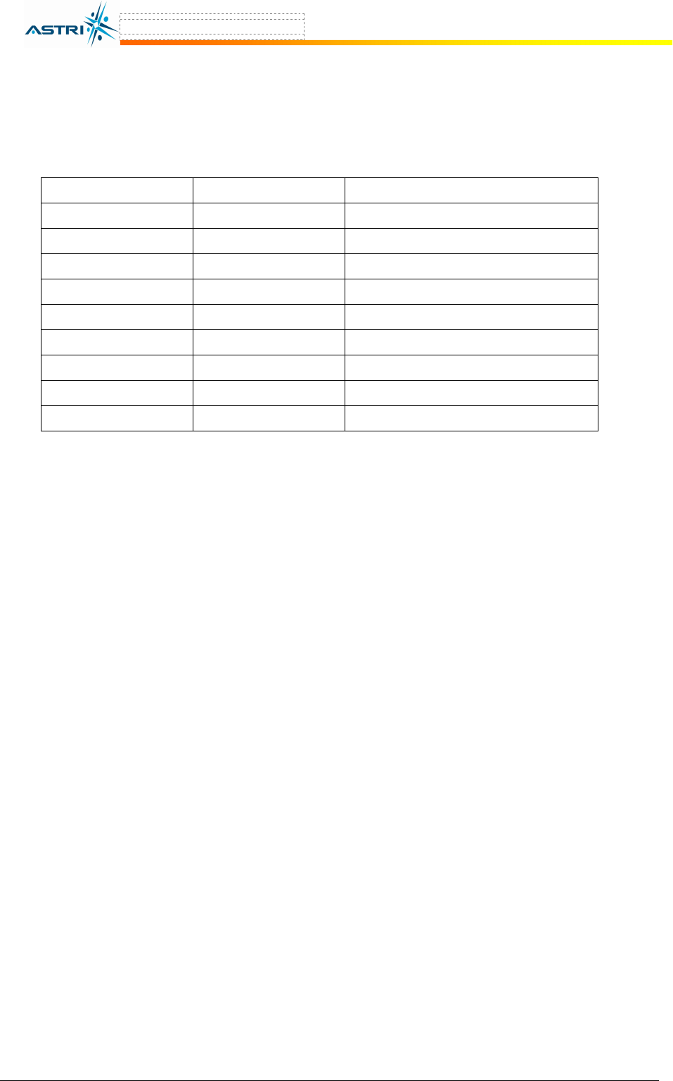
Command line syntax of setting IP:
set ip <ip address of A8>
set ipmask <subnet mask>
set gateway <ip address of gateway>
reboot
You must reboot the A8 to activate this setting.
Example:
set ip 192.168.0.30
set ipmask 255.255.255.0
set gateway 192.168.0.1
reboot
P
ARAMETER
R
ANGE
C
OMMAND
E
XAMPLE
ipaddr <ip address> Set ip 192.168.0.30
ipmask <subnet mask> Set ipmask 255.255.255.0
gateway <ip address> Set gateway 192.168.0.1
Dhcpc Enable / disable Set dhcpc enable
Figure 4. An example of setting IP address
3.5.2 Dynamic IP Setting
The A8 can acquire a dynamic IP address from a DHCP server by the following command:
set dhcpc enable
reboot
This function can be disabled by the following command:
set dhcpc disable
reboot
You must reboot the A8 to activate this setting.

A8 Configuration Manual - fm_1.2.6.3_v4.1.FCC.doc ASTRI Confidential & Restricted Access
Page 9 of 36
3.6 R
ADIO CONFIGURATION
The following parameters related to radio interface will be discussed.
P
ARAMETER
R
ANGE
C
OMMAND
E
XAMPLE
channel 1 – 11 Set channel 11
power 0 – 18 Set power all 21
ssid (name of SSID) Set ssid B4
ssidsuppress enabled / disabled Set ssidsuppress enabled
3.6.1 Channel
Command line syntax of setting the channel:
set channel <channel number>
where channel number: 1 - 11
Example:
set channel 11
3.6.2 Transmit Power
Command line syntax of setting transmit power:
set power <sector> <power level>
where sector: all, 0, 1, 2, 3
power level: 0 to 18, integer number in dBm
Note:
You could set the power level for a particular sector 0, 1, 2, 3 at different power level. Also, you
could set all sectors having the same power level. It is recommended to set all sectors at 21dBm;
i.e. sector = all, power = 21.
Example:
set power all 21
The above command sets all sectors transmitting at an output transmit power of 21dBm.
set power 2 17
The above command sets Sector 2 transmitting at an output transmit power of 17dBm.
Note: In order to comply with the FCC and Industry rules, please refer to Section 11 for the
guideline of power setting.
3.6.3 SSID & SSIDsuppress
Command line syntax of setting SSID:
set ssid <ssid>
where <ssid>: max. 10 alphanumeric characters
Example:
set ssid testing
Command line syntax of suppressing SSID:
set ssidsuppress enable
reboot
A8 Configuration Manual - fm_1.2.6.3_v4.1.FCC.doc ASTRI Confidential & Restricted Access
Page 10 of 36
You must reboot the A8 to activate this setting.
3.7 A
DVANCED
C
ONFIGURATION
More A8 Settings
P
ARAMETER
R
ANGE
C
OMMAND
E
XAMPLE
Factory <none> Set factory
SNTPServer <ip address> Set sntpserver 10.0.0.5
TZONE -12 to +14 Set tzone +8
Time <none> Get time
acl Strict Set acl strict
acl Allow Set acl allow 00:01:22:f4:56:e8
acl Del Del acl 00:22:33:44:55:66
Config Virtual 0 to 7 Config virtual 2
Active Enable / Disable Set active enable
3.7.1 NTP (Network Time Protocol)
Command line syntax of collecting clock information from a NTP server:
set sntpserver 10.5.5.100
set tzone +8
reboot
where 10.5.5.100 is the NTP’s IP address
Note: You must reboot the A8 to activate this setting. You could check the clock by:
get time
3.7.2 ACL Configuration
Command line syntax of setting the ACL:
set acl strict
set acl <allow or deny> <client wlan card mac address>
reboot
An entry in the ACL can be removed as follows:
del acl <client wlan card mac address>
reboot
You must reboot the A8 to activate this setting.
Example:
set acl strict
set acl allow 00:20:A6:34:5E:23
del acl 00:02:20:30:44:55
reboot
A8 Configuration Manual - fm_1.2.6.3_v4.1.FCC.doc ASTRI Confidential & Restricted Access
Page 11 of 36
3.7.3 Encryption (WEP)
Command line syntax of setting the WEP:
set encryption enable
set auth <open/shared/auto/WPA/WPA-PSK/WPA2/WPA2-PSK/WPA-AUTO/WPA-AUTO-PSK>
set keyentry <HEX/ASCII>
set key <1/2/3/4> <40/104/128> <KEY#>
reboot
You must reboot the A8 to activate this setting.
Example:
Set encry enable
Set auth shared
Set keyentry hex
Set key 1 40 1234567890
reboot
Note: It is easier to configure encryption in web-admin interface. Please refer to section 5.4.4 for
the details.
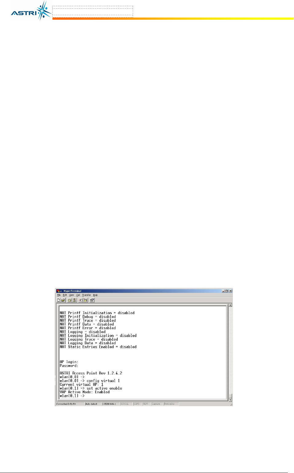
3.7.4 VAP (Virtual AP)
With the default settings, only virtual AP 0 is enabled. You could enable and configure VAPs by
the following CLI:
Config virtual <VAP#>
set active <enable/disable>
where <VAP#> is from 0 to 7, default is 0.
Note: A Reboot is not required to active this function. You could configure the corresponding
SSID, ACL, etc… under this virtual AP number.
Example:
Figure 5. VAP configuration in CLI
A8 Configuration Manual - fm_1.2.6.3_v4.1.FCC.doc ASTRI Confidential & Restricted Access
Page 12 of 36
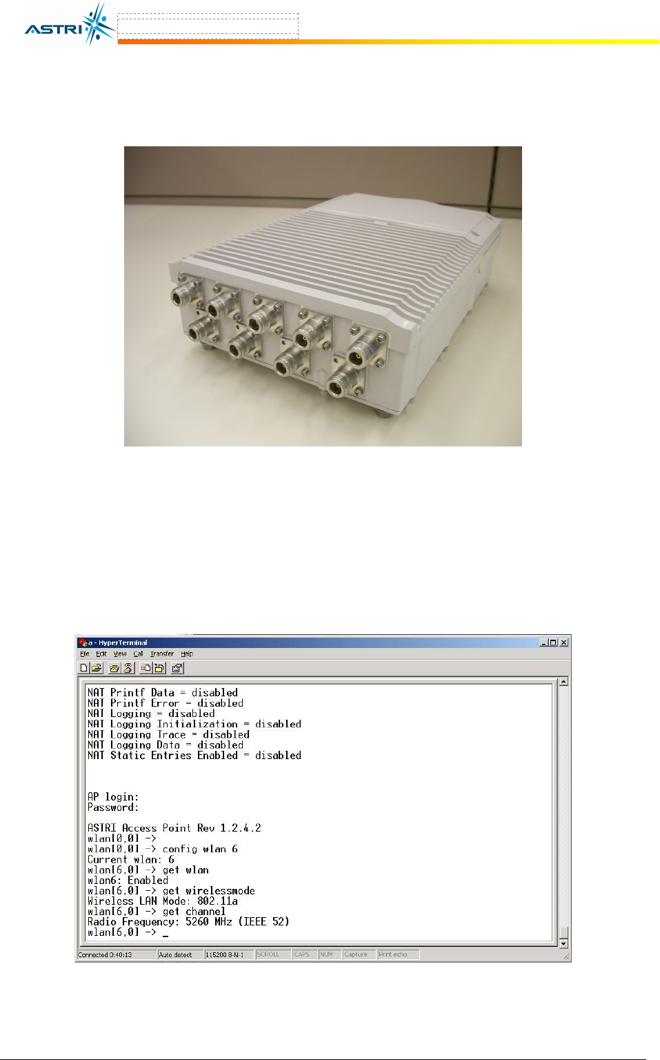
3.8 802.11
A
B
RIDGE
802.11a function is an optional function requiring hardware to support. Only an A8 BTS having
a connector at the ‘a’ port can support this function, as shown in Figure 6.
Figure 6. A8 BTS with 802.11a bridge hardware – “a” port
The 802.11a bridge function is configured via WLAN 6 and is enabled in the default setting. It is
also set to transmit at maximum output power. You could use the following command to check
its state.
Config wlan 6
get wlan
get wirelessmode
Example:
Figure 7. 802.11a in A8 BTS
A8 Configuration Manual - fm_1.2.6.3_v4.1.FCC.doc ASTRI Confidential & Restricted Access
Page 13 of 36
P
ARAMETER
R
ANGE
C
OMMAND
E
XAMPLE
Config wlan 0 or 6 Config wlan 6
Wlan Enable / disable Set wlan enable
Channel 5180, 5200, 5220, 5240,
5260, 5280, 5300, 5320,
5745, 5765, 5785, 5805,
5825
Set channel 5765
PowerReduction 0 – 17 (1dB per unit) Set powerreduction 10
RemoteWbr (MAC address of remote
bridge)
Add remotewbr 00:02:6F:23:12:34
The 802.11a output power is set to maximum value, which is 17dBm. The parameter
PowerReduction is used to reduce the output power relative to the maximum value. So, the
default value of PowerReduction = 0. If you want to reduce the 802.11a output power by 5dB,
you could type the following command in CLI:
Set Powerreduction 5
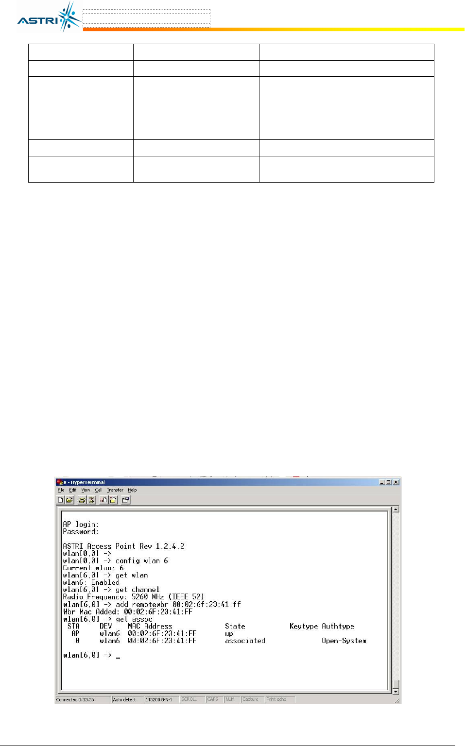
The following command is used to add or delete the remote bridge:
Add remotewbr <WBR MAC address>
Del remotewbr <WBR MAC address>
reboot
where <WBR MAC address> is the MAC address of the remote wireless bridge.
You could also view the number of remote wireless bridges configured with this A8:
Get association
Example:
Assuming you are trying to connect two A8’s with the following MAC address information:
A8_BTS_1 : 00:02:6f:23:41:EE
A8_BTS_2 : 00:02:6f:23:41:FF
In the CLI of A8_BTS_1:
Figure 8. Example – add remote wireless bridge

A8 Configuration Manual - fm_1.2.6.3_v4.1.FCC.doc ASTRI Confidential & Restricted Access
Page 14 of 36
Repeat the setting in A8_BTS_2. You may need to reboot the BTS to make the setting effective.
Note: Since the 802.11b/g and 802.11a radios are sharing the same IP address, no additional IP
address is required. Please note that 802.11a turbo A mode is not supported by the hardware at
this moment.
3.9 R
ESTORE
C
ONFIGURATOIN TO
D
EFAULT
S
ETTING
Command line syntax of restoring A8 to its default setting:
set factory
reboot
After the A8 rebooted, all parameters will be restored to its default values, except IPAddr,
IPMask and Gateway.
Note: You must “reboot” to restore the default settings. Don’t make any parameter changes
after typing the command “set factory” in CLI before allowing the unit to reboot.
A8 Configuration Manual - fm_1.2.6.3_v4.1.FCC.doc ASTRI Confidential & Restricted Access
Page 15 of 36
4 S
OFTWARE
U
PGRADE VIA THE
CLI
4.1 F
IRMWARE
U
PGRADE
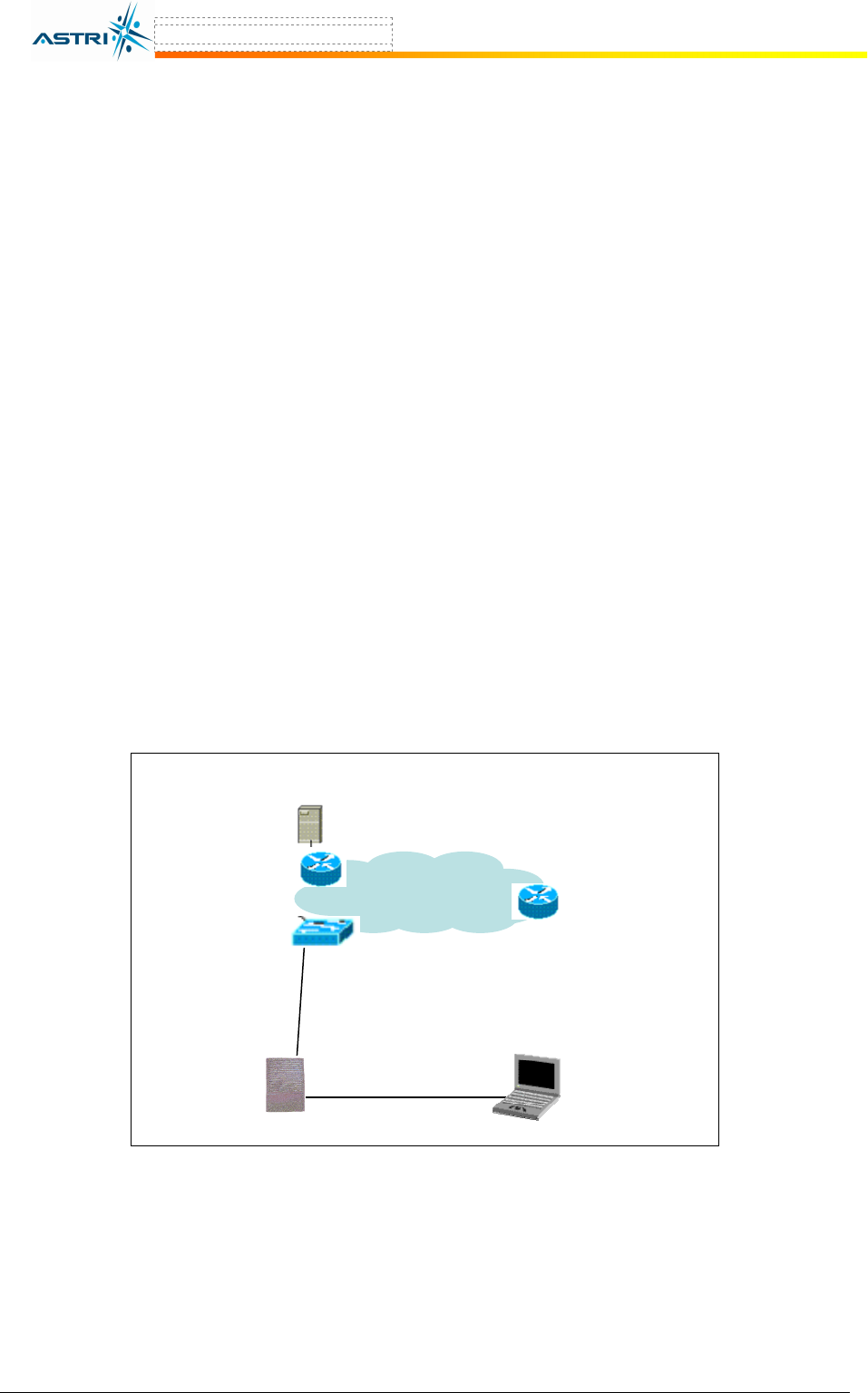
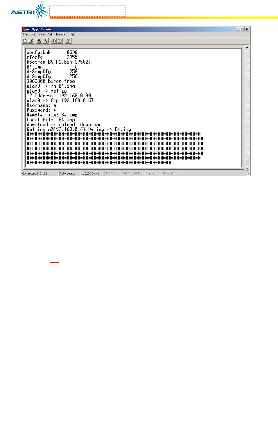
The firmware upgrade procedure is shown below:
1. Store the new firmware in the FTP Server. The name of the new firmware should be
B4.img.
2. Create a user profile in the FTP server.
3. Connect the FTP server and the A8 onto the network; check the connection between the
A8 and FTP server (e.g. by ping).
4. AT the A8 CLI, login to the FTP server and then download the new firmware from the
FTP server into the A8. Figure 10 shows an example.
For this example the settings are:
A8 IP address : 192.168.0.30
FTP Server IP : 192.168.0.67
Username in FTP Server : a (your ftp user name)
New firmware filename : B4.img
5. Wait until the download is completed. Check if the firmware has successfully
downloaded by using the command ls in the CLI.
6. Reboot the A8 with the command reboot.
7. After rebooting, login to the A8 and check if the new firmware is successfully loaded
using the command version.
B8
Switch
FTP Server
Notebook
(as console)
Ethernet
Console
Figure 9. Setup for firmware transfer and upgrade
A8 Configuration Manual - fm_1.2.6.3_v4.1.FCC.doc ASTRI Confidential & Restricted Access
Page 16 of 36
Figure 10. Downloading new firmware from FTP Server
4.2 FPGA
U
PGRADE
The FPGA upgrade procedure is similar to Section 4.1, except that the FPGA file name is
fpga.hex.
Warning: The A8 BTS will not be working properly if there is some mistaken in the upgrade
process. You are not advised to perform firmware or FPGA upgrade if you have no received
any training from ASTRI or its partners.
A8 Configuration Manual - fm_1.2.6.3_v4.1.FCC.doc ASTRI Confidential & Restricted Access
Page 17 of 36
5 C
ONFIGURATION BY
W
EB
-A
DMIN
5.1 IE
C
ONNECTION
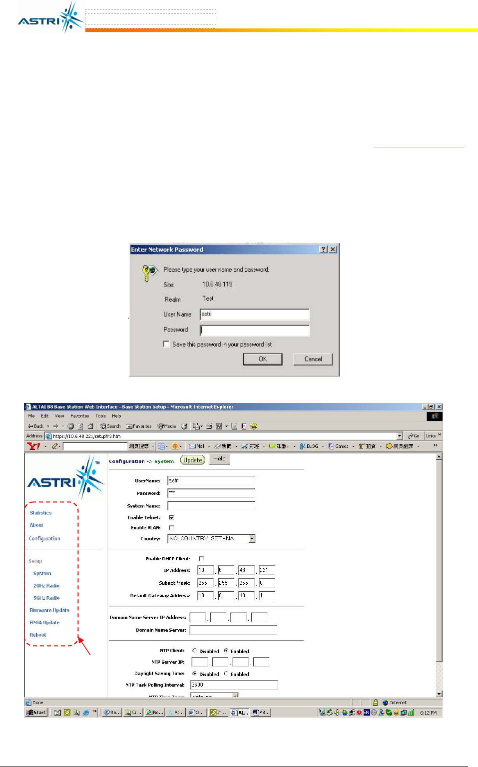
The A8 can be accessed through Internet Explorer (IE).
1. Open an IE session and type the ip address of the A8. Example: https://10.6.48.119,
where 10.6.48.119 is the A8’s IP address. The default IP address is 192.168.1.222.
2. A window will pop up. Enter the user name and password, which are the same as for the
CLI.
3. A login page in IE appears, as shown in Figure 12. A Tool Bar is located on the left
hand side of the IE window. You can access different functions through the tool bar.
Figure 11. Enter User name and password
Tool Bar
Figure 12. Web-admin Login Page
A8 Configuration Manual - fm_1.2.6.3_v4.1.FCC.doc ASTRI Confidential & Restricted Access
Page 18 of 36
5.2 C
HECKING THE
A8
F
IRMWARE
V
ERSION
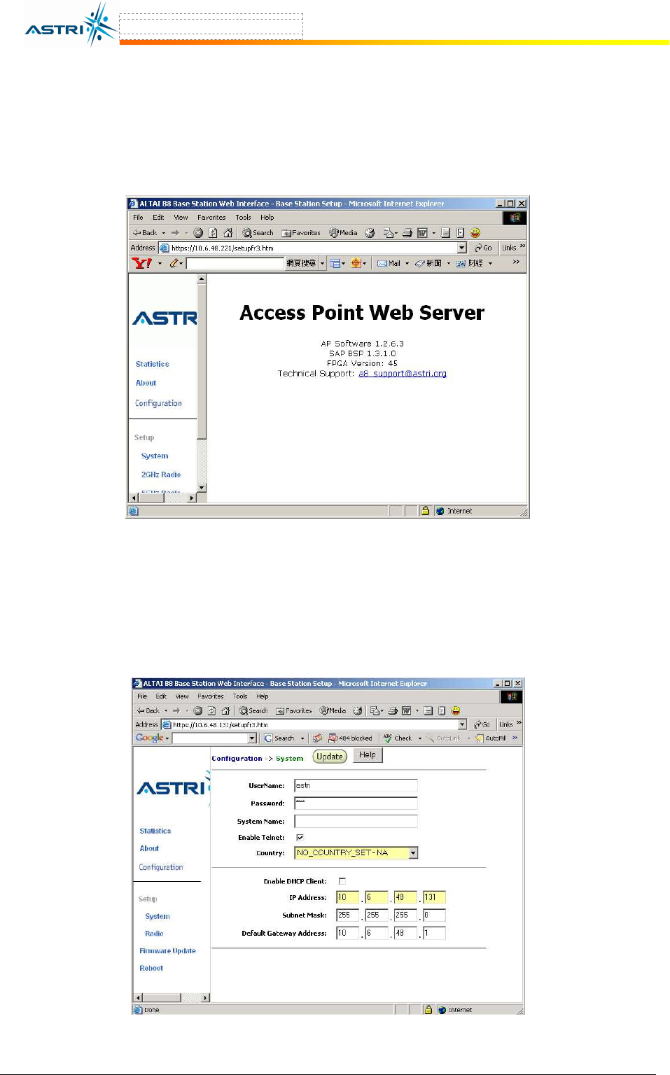
The running version can be checked by selecting About in the menu bar. In Figure 13, the
firmware version is 1.2.6.3. FPGA version is 45. SAP BSP stands for Smart Access Point Board
Support Package, which is hardware related version number.
Figure 13. Firmware Version
5.3 S
ETUP
–
IP
A
DDRESS
The user can configure the IP address by selecting System in the tool bar, as shown in Figure 14.
By clicking the box of Enable DHCP Client and button Update, the A8 BTS will acquire a
dynamic IP address from the DHCP server after reboot.
Figure 14. IP Address Configuration

A8 Configuration Manual - fm_1.2.6.3_v4.1.FCC.doc ASTRI Confidential & Restricted Access
Page 19 of 36
5.4 S
ETUP
–
R
ADIO
P
ARAMETER
The Channel, Output Power, SSID, and VAP (Virtual AP) can be configured by selecting Radio
in the tool bar, as shown in Figure 15.
5.4.1 Output Power
You can set the power for each sector in this area. You may also turn ON or OFF any sector
individually by selecting Disabled or Enabled in State.
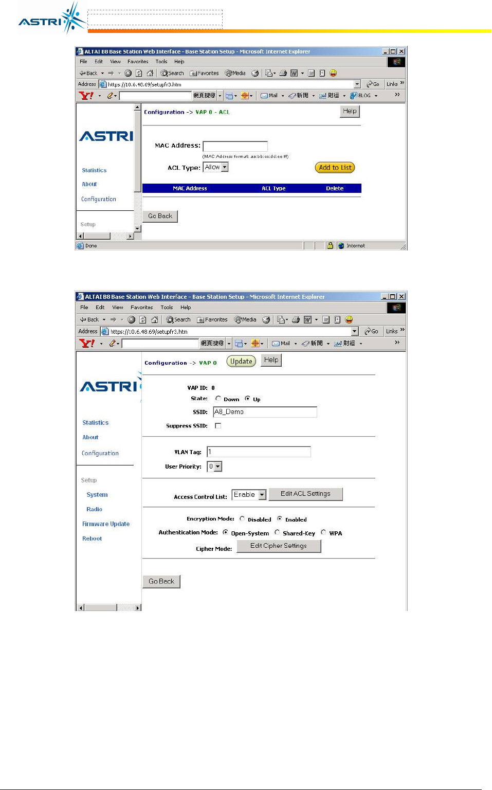
5.4.2 SSID & VAP
For the VLAN, a single VAP is enabled in the default settings. The enabled VLAN, or VAP ID,
is indicated by the Up State, as shown in Figure 15.
The user can alter the individual VAP setting (including SSID) by selecting SSID. The setting of
each VAP is shown in Figure 16.
5.4.3 ACL
The ACL can be enabled by selecting Strict in the Access Control List in Figure 16. Clicking
Edit ACL Settings, a window, as shown in Figure 17, is shown to add MAC address (allow or
deny).
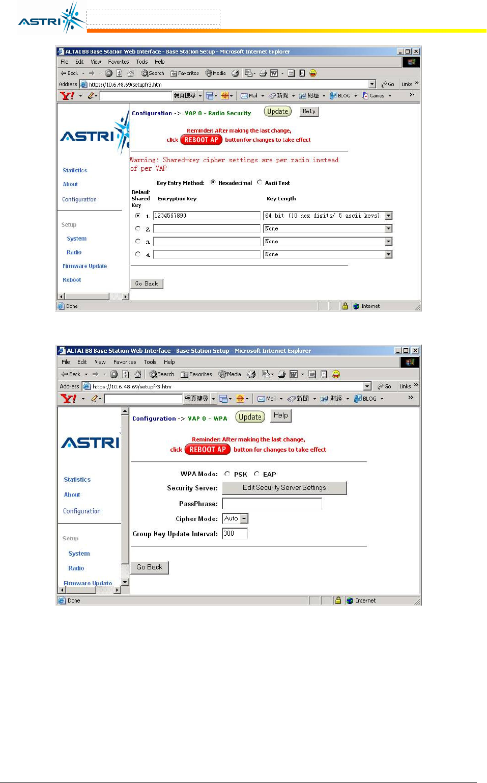
5.4.4 Encryption & Authentication
The encryption can be enabled by clicking the Enabled button in Figure 18.
After selecting Open-System or Shared-Key, the WEP key settings can be defined by clicking
the button Edit Cipher Settings, as in Figure 19.
WPA can be enabled by selecting WPA in Figure 18. The related settings are shown in Figure
20.
Note: Click the button Update to store the WEP or WPA settings.
A8 Configuration Manual - fm_1.2.6.3_v4.1.FCC.doc ASTRI Confidential & Restricted Access
Page 20 of 36
Figure 15. Radio Parameter Configuration
Figure 16. VAP Setting
A8 Configuration Manual - fm_1.2.6.3_v4.1.FCC.doc ASTRI Confidential & Restricted Access
Page 21 of 36
Figure 17. adding MAC list
Figure 18. Enabling Encryption Mode
A8 Configuration Manual - fm_1.2.6.3_v4.1.FCC.doc ASTRI Confidential & Restricted Access
Page 22 of 36
Figure 19. WEP Key Settings
Figure 20. WPA Settings