Microelectronics Technology WA8011-B A8 802.11b/g AP BS AC User Manual Manual 2
Microelectronics Technology Inc A8 802.11b/g AP BS AC Manual 2
Contents
- 1. Manual 1
- 2. Manual 2
Manual 2
A8 Configuration Manual - fm_1.2.6.3_v4.1.FCC.doc ASTRI Confidential & Restricted Access
Page 23 of 36
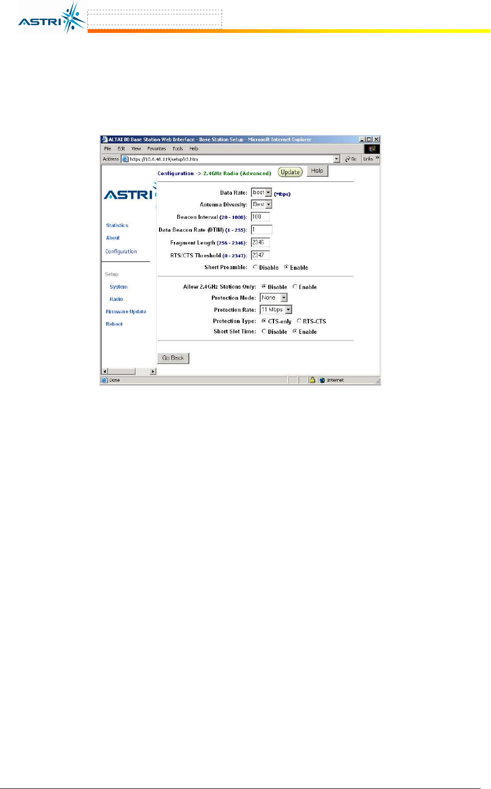
5.4.5 Advanced Radio Setting
More radio parameters can be verified and altered by selecting the Advanced icon shown in
Figure 15. The parameters are shown in Figure 21.
Figure 21. Advanced Radio Setting
5.5 802.11
A
S
ETTING IN
W
EB
-
ADMIN
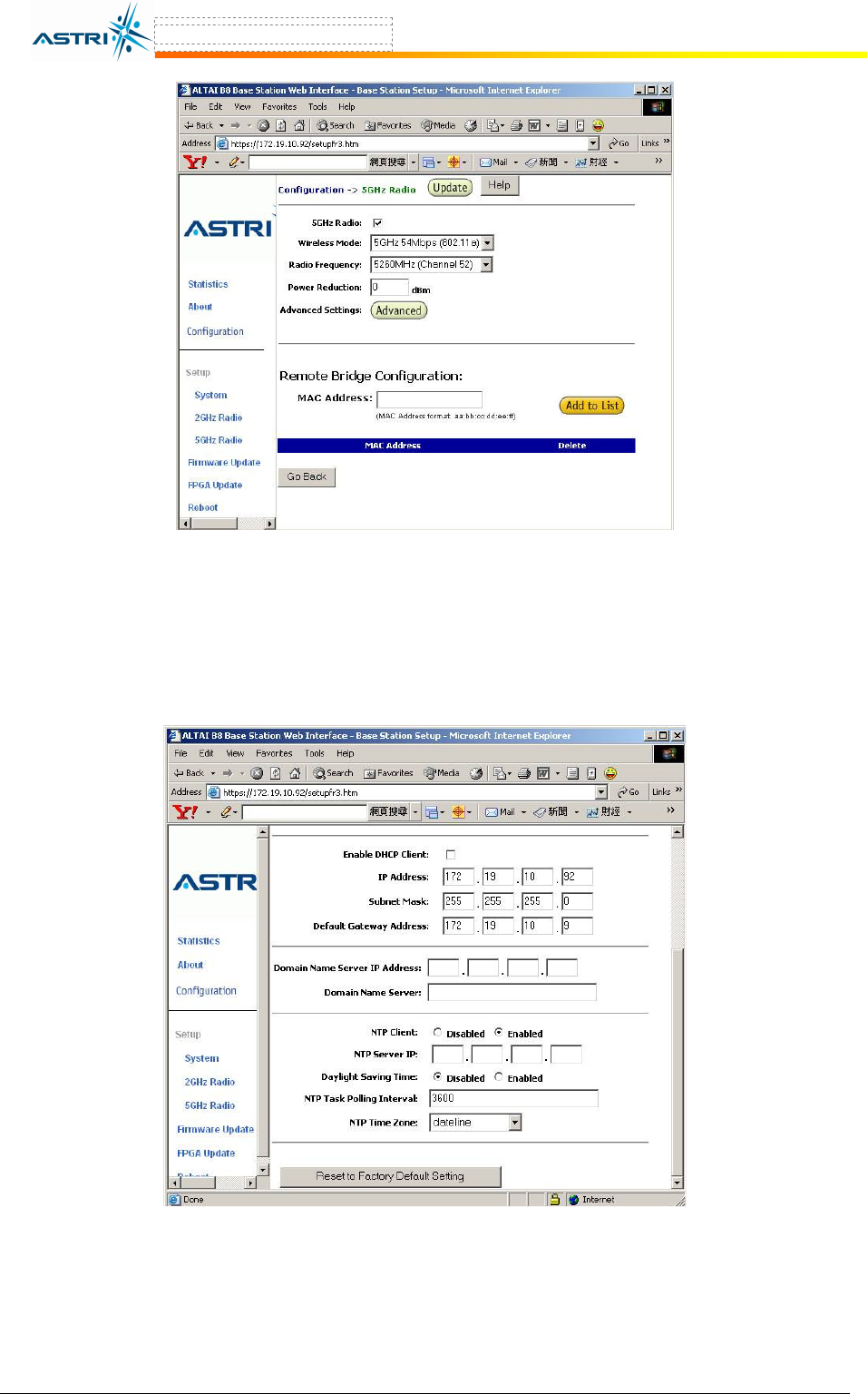
The user can enable the 802.11a port by selecting 5GHz Radio in menu bar, in Figure 22.
The MAC address of the opposite bridge should be added by clicking the icon Add to List. Also,
both bridges should be set at the same Radio Frequency.
The 802.11a output power is set to be maximum in default setting, i.e. Power Reduction = 0.
The maximum output power is 17dBm. The user could reduce the output power to 0dBm, i.e. set
Power Reduction = 17.
A8 Configuration Manual - fm_1.2.6.3_v4.1.FCC.doc ASTRI Confidential & Restricted Access
Page 24 of 36
Figure 22. 802.11a Setting in Web-admin
5.6 D
EFAULT
S
ETTING IN
W
EB
-A
DMIN
The default settings can be restored by clicking the icon “Reset to Factory Default Setting” in
the System menu in Figure 23. Please reboot the BTS afterwards.
Figure 23. Reset to Factory Default Setting in Web-admin
5.7 R
EBOOT
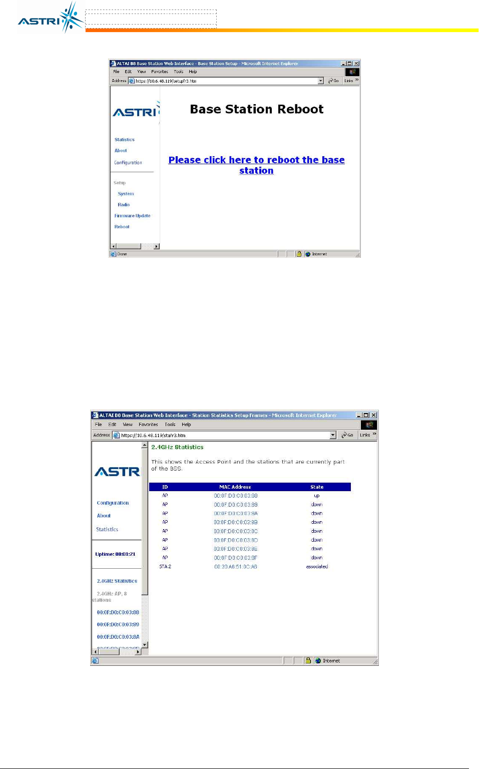
The BTS can be rebooted by selecting Reboot from the tool bar. The user is required to confirm
this command by clicking “Please click here to reboot the base station”, as shown in Figure
23. It will take around 1 minute for the base station to boot up.
A8 Configuration Manual - fm_1.2.6.3_v4.1.FCC.doc ASTRI Confidential & Restricted Access
Page 25 of 36
Figure 24. Reboot Window
6 P
ERFORMANCE
M
ANAGEMENT
M
ONITORING
W
EB
-A
DMIN
6.1 S
TATISTICS
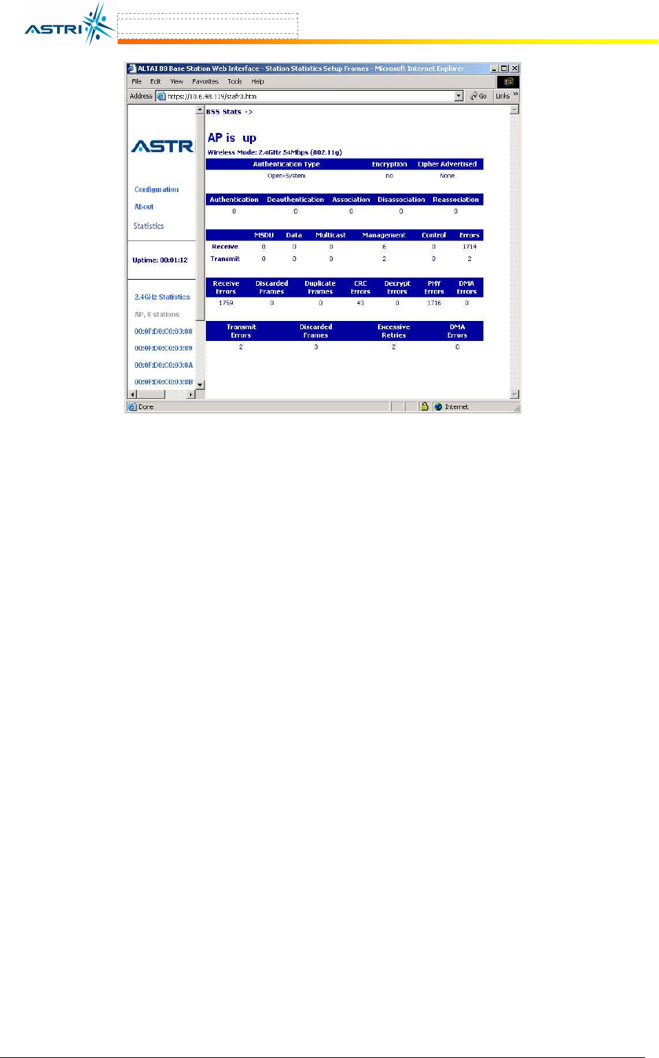
The user can monitor the statistics by selecting Statistics in the tool bar. The corresponding
statistics per AP can be selected by clicking the related MAC address, as shown in Figure 25 and
Figure 26.
Figure 25. Statistics Menu
A8 Configuration Manual - fm_1.2.6.3_v4.1.FCC.doc ASTRI Confidential & Restricted Access
Page 26 of 36
Figure 26. Statistics per VAP
A8 Configuration Manual - fm_1.2.6.3_v4.1.FCC.doc ASTRI Confidential & Restricted Access
Page 27 of 36
7 S
OFTWARE
U
PGRADE BY
W
EB
-A
DMIN
7.1 F
IRMWARE
U
PDATE
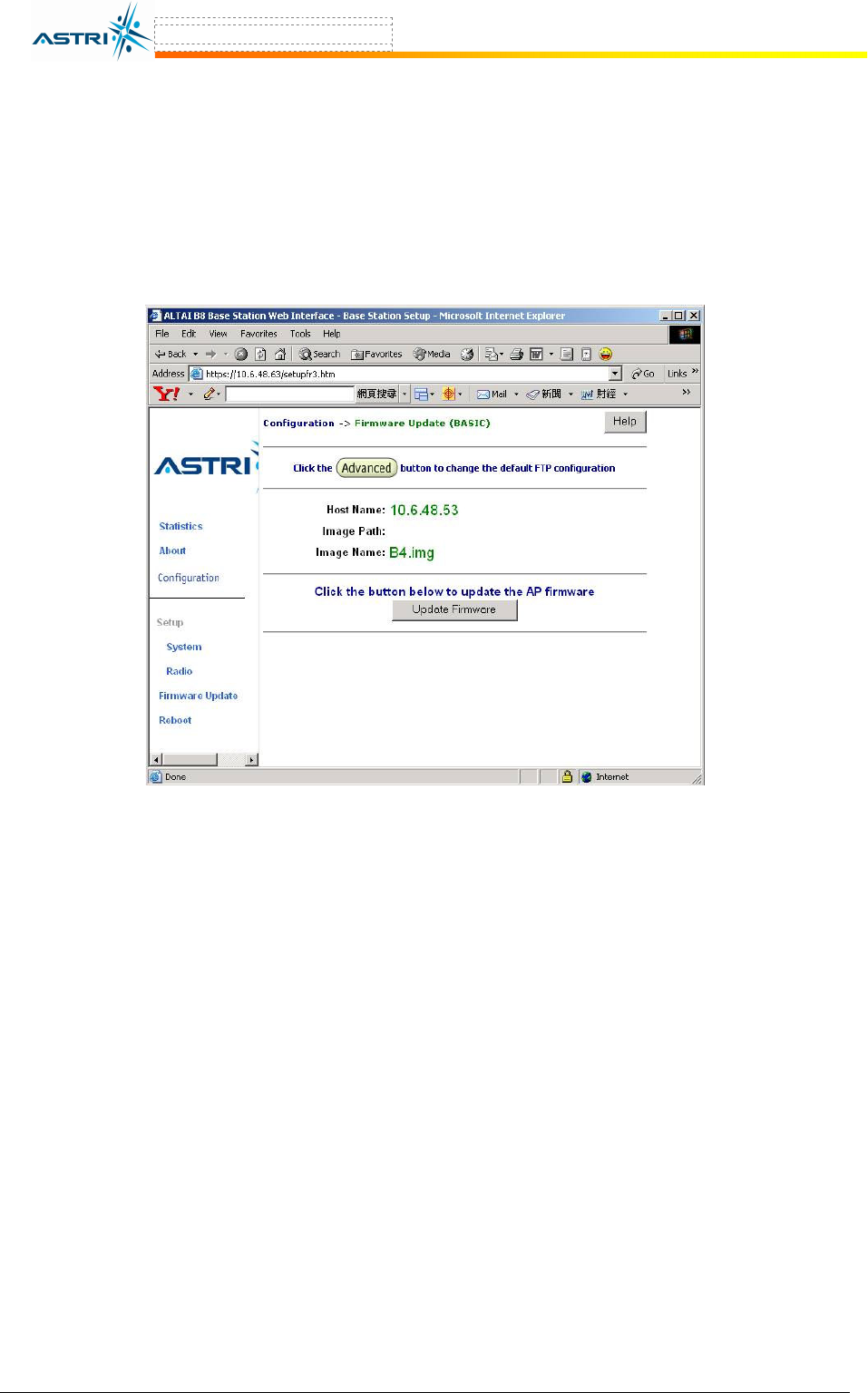
The user can upgrade the firmware by selecting Firmware Update in the tool bar.
In the Firmware Update (BASIC) menu, click the icon Update Firmware if the FTP server
setting has been defined before, as shown in Figure 27.
Figure 27. Firmware Update (Basic) – Web-admin
Update the FTP server setting by clicking the Advanced icon and perform the following:
1. Update the FTP information, as shown in Figure 28.
- Host Name : IP address of the FTP server, where the new firmware is stored
- User Name : The FTP user name
- Password : The password of the FTP user
- Image Path : The location of the file in the FTP server
- Image Name : The new firmware file. It must be B4.img.
2. Select Update Firmware at the bottom to start uploading the new firmware from the
FTP server.
3. If the firmware upgrade is successful, a window will appear as Figure 29. Click the iocn
REBOOT AP to reboot the A8.
4. Check the firmware version by selecting About in the menu bar, as discussed in Section
5.2.

A8 Configuration Manual - fm_1.2.6.3_v4.1.FCC.doc ASTRI Confidential & Restricted Access
Page 28 of 36
Figure 28. Firmware Update (Advanced) – Web-admin
Figure 29. Successful Firmware Update – Web-admin

A8 Configuration Manual - fm_1.2.6.3_v4.1.FCC.doc ASTRI Confidential & Restricted Access
Page 29 of 36
8 B
OOT FROM A
FTP
S
ERVER
8.1 B
OOT FROM NETWORK
The A8 may be booted from a firmware image located on a remote FTP server. This also
provides an alternative method to boot the A8 if there is no available firmware inside the A8.
1. Store the new firmware image in the FTP Server. The name of the new firmware should
be B4.img.
2. Create a user in the FTP server. Please refer to section 10 if you are not familiar with
how to configure a user account on the FTP server.
3. Connect the FTP server and A8 onto the network; check the connection from the FTP
server to the A8 using a ping command (or similar).
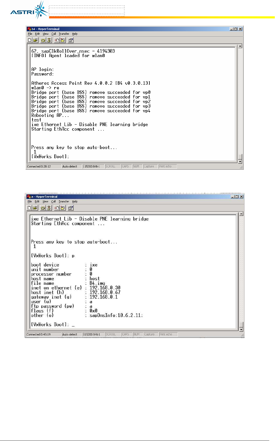
4. From the A8 CLI (connected through console), reboot the A8. Press any key to stop the
reboot when you see the command “Press any key to stop auto-boot…” in the
CLI window. The A8 will go to the BootROM state, as shown in Figure 30.
5. Type “c” to change the settings in the BootROM, as shown in “bold” letter:
- boot device : ixe
- unit number : 0
- processor number : 0
- host name : host
- file name : B4.img
- inet on Ethernet (e) : <your A8 ip address>
- host inet (h) : <your ftp server ip address>
- gateway inet (g) : <gateway ip address>
- user (u) : <your ftp username>
- ftp password (pw) : <your ftp password>
- flags (f) : 0x0
- other (o) :
- startup script : factory
6. Type “p” to check if the settings are correct, as shown in Figure 31.
1. And then, type “@” to reboot the A8 from the BootROM.
2. Check the current firmware version with the command version in the CLI. You may
also check the memory and file size in the flash memory with the command ls in the
CLI.
A
TTENTION
:
Booting from the network will not download any firmware to the local flash device inside the
A8. If you want to boot with the same firmware without booting from network, you must first
download the firmware to the A8 Flash memory. Please refer section 4.1 for the details.
A8 Configuration Manual - fm_1.2.6.3_v4.1.FCC.doc ASTRI Confidential & Restricted Access
Page 30 of 36
Figure 30. Go to A8 BootROM
Figure 31. Network Boot Setting in BootROM
A8 Configuration Manual - fm_1.2.6.3_v4.1.FCC.doc ASTRI Confidential & Restricted Access
Page 31 of 36
8.2 B
OOT FROM LOCAL FLASH DEVICE
If there is firmware loaded into the A8 memory and you want to change the booting process
from the FTP server to the local memory, you must change the parameters in the BootROM.
1. From theA8 CLI (connected through console), reboot the A8. Press any key to stop the
reboot when you see the command “Press any key to stop auto-boot…” in the
CLI window. The A8 will go to the BootROM state.
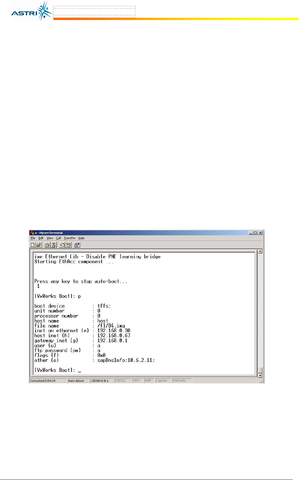
2. Type “c” to change the settings in the BootROM, as shown in “bold” letter:
- boot device : tffs:0
- unit number : 0
- processor number : 0
- host name : host
- file name : /fl/B4.img
- inet on ethernet (e) : <your A8 ip address>
- host inet (h) : <your ftp server ip address>
- gateway inet (g) : <gateway ip address>
- user (u) : <your ftp username>
- ftp password (pw) : <your ftp password>
- flags (f) : 0x0
- other (o) :
- startup script : factory
3. Type “p” to check if the settings are correct, as shown in Figure 32.
4. And then, type “@” to reboot the A8 from the BootROM.
Figure 32. Local Boot Setting in BootROM
A8 Configuration Manual - fm_1.2.6.3_v4.1.FCC.doc ASTRI Confidential & Restricted Access
Page 32 of 36
9 A8
R
ECOVERY
9.1 B
OOT
-
UP FROM
B
OOT
ROM
If the A8 cannot boot up due to incorrect boot parameters, it can be recovered by booting up to
the BootROM asoutline below:
1. Connect to the A8 using a serial console cable.
2. From the A8 CLI (connected to the console), reboot the A8. Press any key to stop the
reboot when you see the command “Press any key to stop auto-boot…” in the
CLI window. The A8 will go to BootROM state, as shown in Figure 30.
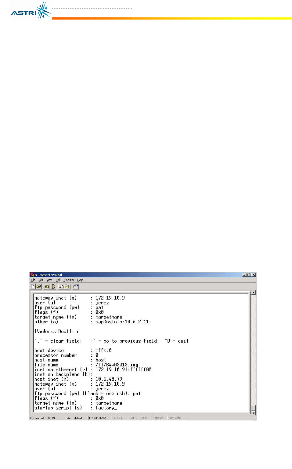
3. Type “c” and enter a command “factory” in the setting “startup script” in
BootROM, as shown in “bold” letters:
- boot device : ixe
- unit number : 0
- processor number : 0
- host name : host
- file name : B4.img
- inet on ethernet (e) : <your A8 ip address>
- host inet (h) : <your ftp server ip address>
- gateway inet (g) : <gateway ip address>
- user (u) : <your ftp username>
- ftp password (pw) : <your ftp password>
- flags (f) : 0x0
- other (o) :
- startup script : factory
4. Type “p” to check if the setting is correct, as shown in Figure 33.
5. And then, type “@” to reboot the A8 from the BootROM. The A8 will boot up with the
factory default settings.
Figure 33. Enter command “factory” in startup script of BootROM
A8 Configuration Manual - fm_1.2.6.3_v4.1.FCC.doc ASTRI Confidential & Restricted Access
Page 33 of 36
10 C
ONFIGURE A USER ACCOUNT IN THE
FTP
S
ERVER
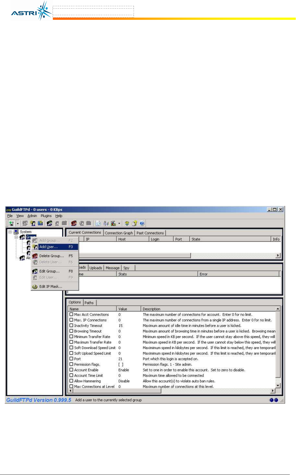
This section will show how to configure a user account in the FTP server software. GuildFTPd
FTP Deamon is used for demonstration purposes.
1. Install the software in the FTP server.
2. Under the System → Group, create a user account, for example “ftpuser”, as shown in
Figure 34.
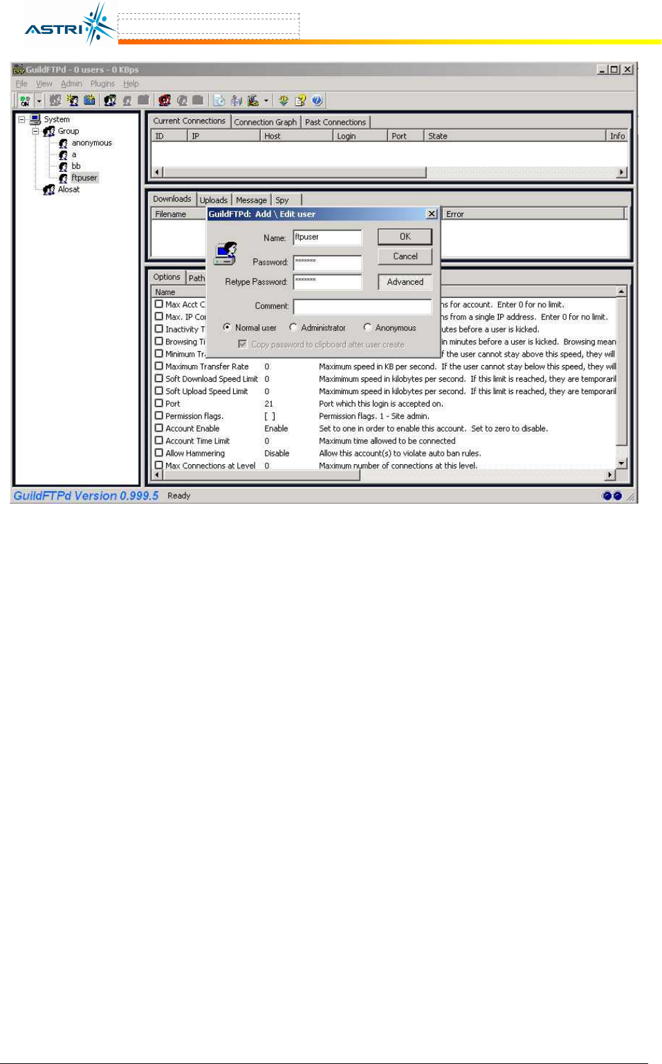
3. After the user account is created, select the user account, and then click the icon “edit
user“ in the tool bar. Switch to Advanced Mode by clicking the bottom “Advanced”
button in the “edit user” window, as shown in Figure 35. Press “Yes” for confirmation.
4. Select the user account again, and then click the icon “add path“ in the tool bar. Click
the bottom “Browse…” buttion, next to “Local path:” to select the location where the
firmware file is stored.
5. The user account has successfully been created. You may download or upload the
firmware using this account.
Figure 34. Creating a FTP user account
A8 Configuration Manual - fm_1.2.6.3_v4.1.FCC.doc ASTRI Confidential & Restricted Access
Page 34 of 36
Figure 35. Activate a user account

A8 Configuration Manual - fm_1.2.6.3_v4.1.FCC.doc ASTRI Confidential & Restricted Access
Page 35 of 36
11 A
NTENNA
U
SAGE AND
T
RANSMIT
P
OWER
In order to comply with the FCC and Industry rules in the USA and other countries, it is required
to set the maximum transmit power limits as follows according to the corresponding antenna
gain.
FCC Certified Antenna Configurations
Maximum Conducted Transmit Power
(EIRP Output power)
Wireless Mode Antenna Type
Channel 1 –
Channel 2
Channel 3 –
Channel 9
Channel 10 –
Channel 11
802.11b 17 dBm
(31dBm EIRP)
20 dBm
(34dBm EIRP)
18 dBm
(32dBm EIRP)
802.11g
14 dBi
(B8-R2-75mm
sector antenna) 11 dBm
(25dBm EIRP)
21 dBm
(35dBm EIRP)
14 dBm
(28dBm EIRP)
FCC Certified Antenna Configurations
Maximum Conducted Transmit Power
(EIRP Output Power)
Wireless Mode Antenna Type
Channel 52 –
Channel 60
Channel 64
10 dBi Omni 19 dBm
(29dBm EIRP)
17 dBm
(27dBm EIRP)
802.11a
18 dBi Directional
11 dBm
(29dBm EIRP)
11 dBm
(29dBm EIRP)
FCC Certified Antenna Configurations
Maximum Conducted Transmit Power
(EIRP Output Power)
Wireless Mode Antenna Gain
Channel 149 –
Channel 161
Channel = 165
8 dBi Omni 18 dBm
(26dBm EIRP)
18 dBm
(26dBm EIRP)
802.11a
18 dBi Directional
Panel
17 dBm
(35dBm EIRP)
21 dBm
(39dBm EIRP)

A8 Configuration Manual - fm_1.2.6.3_v4.1.FCC.doc ASTRI Confidential & Restricted Access
Page 36 of 36
12 A
PPENDIX
–
D
EFAULT
S
ETTING
P
ARAMETER
D
ESCRIPTION
D
EFAULT
V
ALUE
IPADDR A8 IP address 192.168.1.222
IPMASK Subnet mask 255.255.255.0
GATEWAY Gateway’s IP address 192.168.1.1
SSID Name of SSID B4_R1 - 0
SSIDSUPPRESS Suppressing SSID Disabled
CHANNEL Operating frequency 6
POWER RF output power level 21dBm
DHCPC Get Dynamic IP address from DHCP server Disabled
SNTPServer Get clock from NTP server’s IP address (Blank)
TZONE Relative Time zone of the A8 (GMT) 0
TIME Get the current date and time of A8 BTS (Blank)
CONFIG VIRTUAL Go to configure a certain Virtual AP 0
ACTIVE Check the status of the VAP Enable (for VAP 0)
CONFIG WLAN Go to configure a certain WLAN device 0
WLAN Check the status of the WLAN device Enable (for WLAN 0)
POWERREDUCTION 802.11a output power level relative to the
maximum value, which is 17dBm
0
ASSOCIATION Get the AP and Clients associated to the BTS N/A