Microelectronics Technology XS-61X-35 Mobile WiMAX 3.5GHz Outdoor CPE User Manual Revised 0824
Microelectronics Technology Inc Mobile WiMAX 3.5GHz Outdoor CPE Revised 0824
User manual Revised 0824

Page 1 of 35
MTI Proprietary
WiMAX 3.5 GHz Outdoor
Mobile CPE
(XS-61X-35X-XXX)
User Manual
Version 3.0
May 18 , 2009
Microelectronics Technology Inc. Proprietary
Copyright © 2009 Microelectronics Technology Inc.
Notice of Proprietary Information
This document and its contents are proprietary to Microelectronics Technology Inc. and are
intended solely for the internal use of Microelectronics Technology Inc. This publication and its
contents may not be reproduced or distributed for any other purpose without the written
permission of Microelectronics Technology Inc.
WiMAX 3.5 GHz Outdoor Mobile CPE User Manual
Doc No. 56-601-0068

Page 2 of 35
MTI Proprietary
Previous History
Revision Date of Issue Scope Author
1.0 Aug.-15-2008 First draft Ryan K./ Eric H..
1.1 Aug.-20-2008 Modify frequency and channel BW for CE
requirements Patty H.
1.2 Aug.-26-2008 Add File upload and CA certification file
upload procedure Chiyung L.
1.3 Oct -03-2008 Add LED description, Pull-down Box,
MAC Address Cloning, Logout Eric H.
1.4 Oct -06-2008 Modify the model number for both
XS-615-25S-XXX and XS-615-25M-XXX Patty H.
1.5 Nov -18-2008 Remove outlook difference between
XS-615-25S-XXX and XS-615-25M-XXX.
Add detail information for File upload
Patty H.
2.1 Dec.-15-2008 Combine 2.3/2.5 GHz User Manual & add
software version on user manual. This
user manual needs to be operated with
software version
2X0-IR4X-XXXXX-08CX, where “X”:
alpha numbers.
Patty H.
3.0 May-18-2009 Create 3.5 GHz XS-615 & XS-618 User
Manual & add software version on user
manual. This user manual needs to be
operated with software version
2X0-IR4X-XXXXX-BX.X, where “X”: alpha
numbers.
Herman C.
Page 3 of 35
MTI Proprietary
Preface
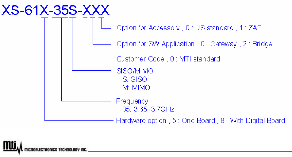
The XS-61X-35X-XXX, where -XXX is defined as -: “-” or blank and XXX: alpha numbers or blank, and we
call it XS-61X-35 series here for short, WiMAX 3.5 GHz Outdoor Mobile CPE, proudly announced by
Microelectronics Technology Inc., is suitable to install in both residential and commercial properties for
WiMAX System operation. With the advantages of high performances and low cost, it operates on WiMAX 3.5
GHz band, offering a perfect wireless solution to extend the internet access coverage.
To meet the stringent outdoor application, the XS-615-35 series incorporates a patterned technology to
ensure the operation of the radio over the wide temperature. The build-in lightning protectors further ensure
the radio and its accessories safety during the operation.
To fulfill the network management requirement, the XS-618-35 series incorporates a TR-069 protocol to
ensure the service provider could manage the CPE over the air.
The document is for the information to know more detail about XS-61X-35 series outdoor CPE. We will
introduce the hardware part and the software configuration. This manual is intended for those people who will
operate the XS-61X-35 series, WiMAX 3.5 GHz Outdoor Mobile CPE.
Option Code Mapping Table

Page 4 of 35
MTI Proprietary
Table of Contents
Previous History ............................................................................................................................................2
Preface ..........................................................................................................................................................3
Table of Contents ..........................................................................................................................................4
Table of Figures.............................................................................................................................................5
Manual Conventions......................................................................................................................................6
Disclaimer......................................................................................................................................................7
1 Introduction ........................................................................................................................8
2 Hardware Features............................................................................................................9
2.1 Product and Accessories ..................................................................................................9
2.2 Outlook and Interface .....................................................................................................10
2.3 Warranty Limitation.........................................................................................................13
3 Software Feature .............................................................................................................15
3.1 Login ...............................................................................................................................15
3.2 System Information.........................................................................................................16
3.3 Subscriber Capability......................................................................................................17
3.4 Network Setting ..............................................................................................................18
3.5 WiMAX Setting................................................................................................................19
3.6 Channel Setting ..............................................................................................................22
3.7 EAP Setting.....................................................................................................................24
3.8 Subscriber Station...........................................................................................................26
3.9 Service Flow (SF) Information ........................................................................................27
3.10 Radio...............................................................................................................................28
3.11 MAC Uplink / Downlink configuration .............................................................................29
3.12 MAC Packet Data Unit (PDU).........................................................................................30
3.13 Downlink Physical (PHY)................................................................................................31
3.14 File Upload......................................................................................................................32
3.15 Logout.............................................................................................................................35
3.16 Reboot ............................................................................................................................35

Page 5 of 35
MTI Proprietary
Table of Figures
Figure 1 Example for usage of WiMAX outdoor CPE........................................................................................8
Figure 2 PoE Cable Connector, Grounding Screw, Status Indicator LEDs .....................................................10
Figure 3 Ethernet Cable Connection to Host PC.............................................................................................11
Figure 4 Ethernet Cable Connection to XS-61X-35 series..............................................................................11
Figure 5 Power Cord Connection to PoE.........................................................................................................12
Figure 6 Greeting Page....................................................................................................................................15
Figure 7 Login ..................................................................................................................................................15
Figure 8 System Information............................................................................................................................16
Figure 9 Subscriber Capability.........................................................................................................................17
Figure 10 Network Setting ...............................................................................................................................18
Figure 11 WiMAX Setting.................................................................................................................................19
Figure 12 MAC Address Clone ........................................................................................................................20
Figure 13 Channel Setting ...............................................................................................................................22
Figure 14 EAP Setting .....................................................................................................................................24
Figure 15 Subscriber Information ....................................................................................................................26
Figure 16 Service Flows Information ...............................................................................................................27
Figure 17 Radio Information ............................................................................................................................28
Figure 18 MAC Uplink / Downlink Configuration..............................................................................................29
Figure 19 MAC Packet Data Unit.....................................................................................................................30
Figure 20 Downlink Physical Statistics ............................................................................................................31
Figure 21 File Upload.......................................................................................................................................32
Page 6 of 35
MTI Proprietary
Manual Conventions
Bold Bold type within paragraph text indicates commands, file names, directory
names, paths, output, or returned values.
Italic Within commands, italics indicate a variable that the user must specify.
Titles of manuals or other published documents are also set in italics.
Courier The courier font indicates output or display.
[] Within commands, items enclosed in square brackets are optional parameters
or values that the user can choose to specify or omit.
{} Within commands, item enclosed in braces are options from which the user
must choose.
| Within commands, the vertical bar separates options.
… An ellipsis indicates a repetition of preceding parameter.
> The right angle bracket separates successive menu selection.
NOTE: This message denotes neutral or positive information that calls out important points to the text. A
note provides information that applies only in special cases.
Caution: Cautions call special attention to hazards that can cause system damage or data
corruption, to a lesser degree than warnings.
Warnings: Warnings call special attention to hazards that can cause system damage, data
corruption, personal injury, or death.

Page 7 of 35
MTI Proprietary
Disclaimer
The MTI WiMAX 3.5 GHz Outdoor Mobile CPE (XS-61X-35 series) User Manual
Document No.: 56-601-0068 (REV: 3.0), May. 18, 2009.
COPYRIGHT © 2009 Microelectronics Technology Inc.
ALL RIGHTS RESERVED
Any part of this publication could not be copied, stored in a retrieval system, or translated into any
language or computer language in any form or any means, electronic, magnetic, chemical, manual or
otherwise, without the prior written permission of Microelectronics Technology Inc. (MTI). No.1, Innovation RD
II, Hsin-Chu Science-Based Industrial Park, Hsin-Chu 300, Taiwan, R.O.C..
Printed in Taiwan
The instructions in this manual have been carefully checked for accuracy and are presumed to be reliable.
The accuracy and adequacy of this document are the responsibilities of Microelectronics Technology Inc.
Please give us any comments or corrections to Microelectronics Technology Inc.
Product appearance and specifications are subject to change without prior notice.
Page 8 of 35
MTI Proprietary
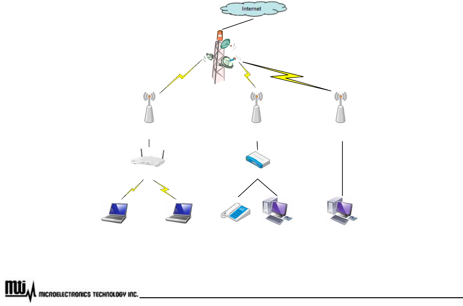
1 Introduction
WiMAX technology is the ideal solution for last-mile broadband wireless access extending high-speed
network connectivity at low installation and operating costs. It is intended to provide total freedom to people
who are fixed, nomadic, or highly mobile, allowing them to stay connected with voice, data and video services.
By using WiMAX, people could go from their houses to their cars, and then travel to their offices or
somewhere else seamlessly.
MTI’s WiMAX Outdoor CPE, XS-61X-35 series, complies with IEEE Standard 802.16e-2005, state of the
art Scalable OFDMA based technology. It operates on 3.65 GHz ~ 3.70 GHz for 3.5 GHz CPE. It supports
different channel bandwidths. The modulation schemes support QPSK, 16QAM, and 64QAM on both uplink
and downlink. This WiMAX Outdoor CPE is designed with weather proof function and lightning protectors for
operation in harshest outdoor environments. In addition, it provides a user-friendly Web browser for user
setup and information sharing.
Figure 1 provides an example of the usage of the WiMAX Outdoor CPE (XS-61X-35 series). Connecting
Wi-Fi AP or VoIP Switch to the WiMAX Outdoor CPE, it is convenient to allow networked devices to share a
high-speed internet connection.
WiMAX BS
WiMAX Outdoor CPE
(XS-615 Series)
WiMAX Link
WiFi Access Point
WiMAX Outdoor CPE
(XS-615 Series)
VoIP Switch
Laptop
WiMAX Outdoor CPE
(XS-615 Series)
Laptop
WiMAX Link
Phone Computer Computer
WiFi Link
WiMAX BS
WiMAX Outdoor CPE
(XS-615 Series)
WiMAX Link
WiFi Access Point
WiMAX Outdoor CPE
(XS-615 Series)
VoIP Switch
Laptop
WiMAX Outdoor CPE
(XS-615 Series)
Laptop
WiMAX Link
Phone Computer Computer
WiFi Link
Figure 1 Example for usage of WiMAX outdoor CPE

Page 9 of 35
MTI Proprietary
2 Hardware Features
2.1 Product and Accessories
XS-61X-35 series Outdoor CPE x 1
2 meters RJ-45 Shield Cable x 1
AC/DC PoE Adapter x 1
Power cord x 1
CD (User manual & Installation guide) x 1
Installation kits x 1 set
Page 10 of 35
MTI Proprietary
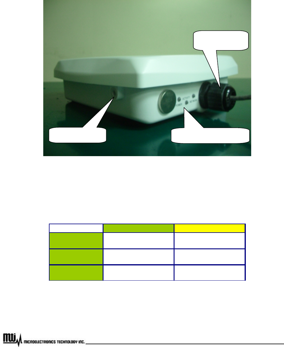
2.2 Outlook and Interface
2.2.1 Power over Ethernet (PoE) Cable Connector
Figure 2 PoE Cable Connector, Grounding Screw, Status Indicator LEDs
2.2.2 Status Indicator LEDs
LED " ON " " OFF "
Power DC power supply
connected successfully
DC power supply
disconnected
Activity WiMAX radio link
connected successfully
WiMAX radio link
disconnected
Network User network device
connected successfully
User network device
disconnected
PoE Cable
Connector
Grounding Screw Status Indicator LEDs
Page 11 of 35
MTI Proprietary
2.2.3 Grounding Screw
For grounding strip connection.
Proper grounding is always for the safety consideration.
Note: Please refer to installation guide for the further setup information.
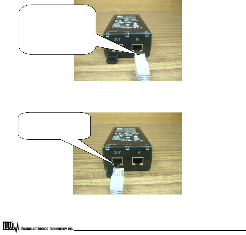
2.2.4 Ethernet Cable Connection
Figure 3 Ethernet Cable Connection to Host PC
Figure 4 Ethernet Cable Connection to XS-61X-35 series
(1) Crossover Ethernet
cable connects to Input port
and link to host PC.
(2) Straight Ethernet cable
connects to Input port and
link to LAN Device (ex.
Switch or Hub)
PoE Ethernet Cable
connect to Output port and
link to XS-61X-35 series
Page 12 of 35
MTI Proprietary
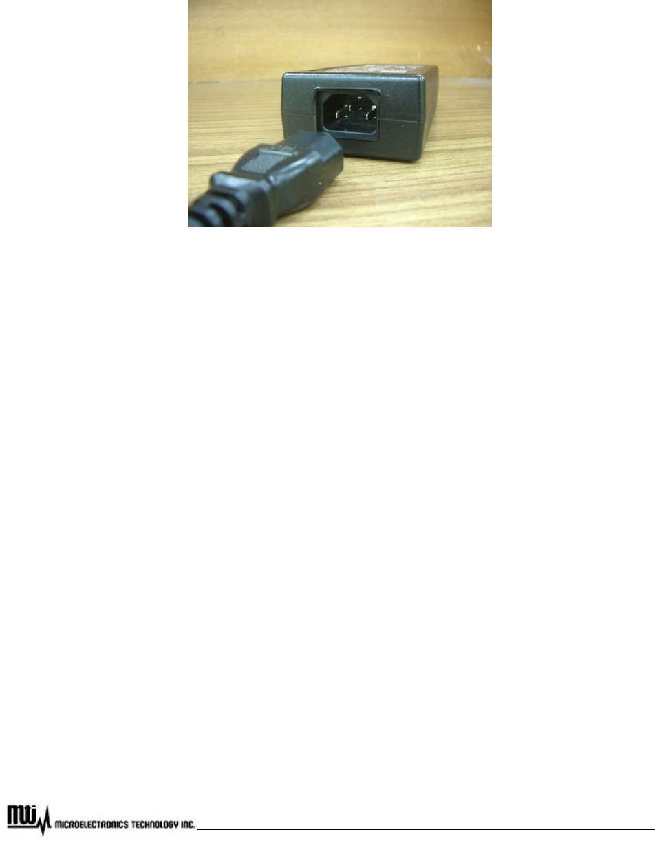
2.2.5 Power Cord Connection
Figure 5 Power Cord Connection to PoE

Page 13 of 35
MTI Proprietary
2.3 Warranty Limitation
MTI will not provide the warranty if the unit is operated out of the following conditions.
Temperature -- The outdoor CPE is tested for normal operation in the ambient temperatures from
-40°C to 60°C. Operating in temperatures outside of this range may cause the unit to fail.
Lightning -- The outdoor CPE includes its own built-in lightning protection. However, customer
should make sure that the unit, any supporting structure, and cables are all properly grounded.
Additional protection using lightning rods, lightning arrestors, or surge suppressors may also be
employed.
Rain -- The outdoor CPE is weatherproofed against rain and prolonged heavy rain has no
significant effect on the radio signal. Customer may need to use the sealing tape around the
Ethernet port connector for extra protection. If moisture enters the connector, it may cause
degradation in performance or even a complete failure of the link.
Under normal use condition, it should be at least 30 cm away from the body of the user.

Page 14 of 35
MTI Proprietary
This equipment has been tested and found to comply with the limits for a Class B digital device,
pursuant to Part 15 of the FCC Rules. These limits are designed to provide reasonable protection against
harmful interference in a residential installation. This equipment generates, uses and can radiate radio
frequency energy and, if not installed and used in accordance with the instructions, may cause harmful
interference to radio communications. However, there is no guarantee that interference will not occur in a
particular installation. If this equipment does cause harmful interference to radio or television reception, which
can be determined by turning the equipment off and on, the user is encouraged to try to correct the
interference by one of the following measures:
- Reorient or relocate the receiving antenna.
- Increase the separation between the equipment and receiver.
- Connect the equipment into an outlet on a circuit different from that to which the receiver is
connected.
- Consult the dealer or an experienced radio/TV technician for help.
FCC Caution: Any changes or modifications not expressly approved by the party responsible for compliance
could void the user's authority to operate this equipment.
This device complies with Part 15 of the FCC Rules. Operation is subject to the following two conditions: (1)
This device may not cause harmful interference, and (2) this device must accept any interference received,
including interference that may cause undesired operation.
This transmitter must not be co-located or operating in conjunction with any other antenna or
transmitter.
Page 15 of 35
MTI Proprietary
3 Software Feature
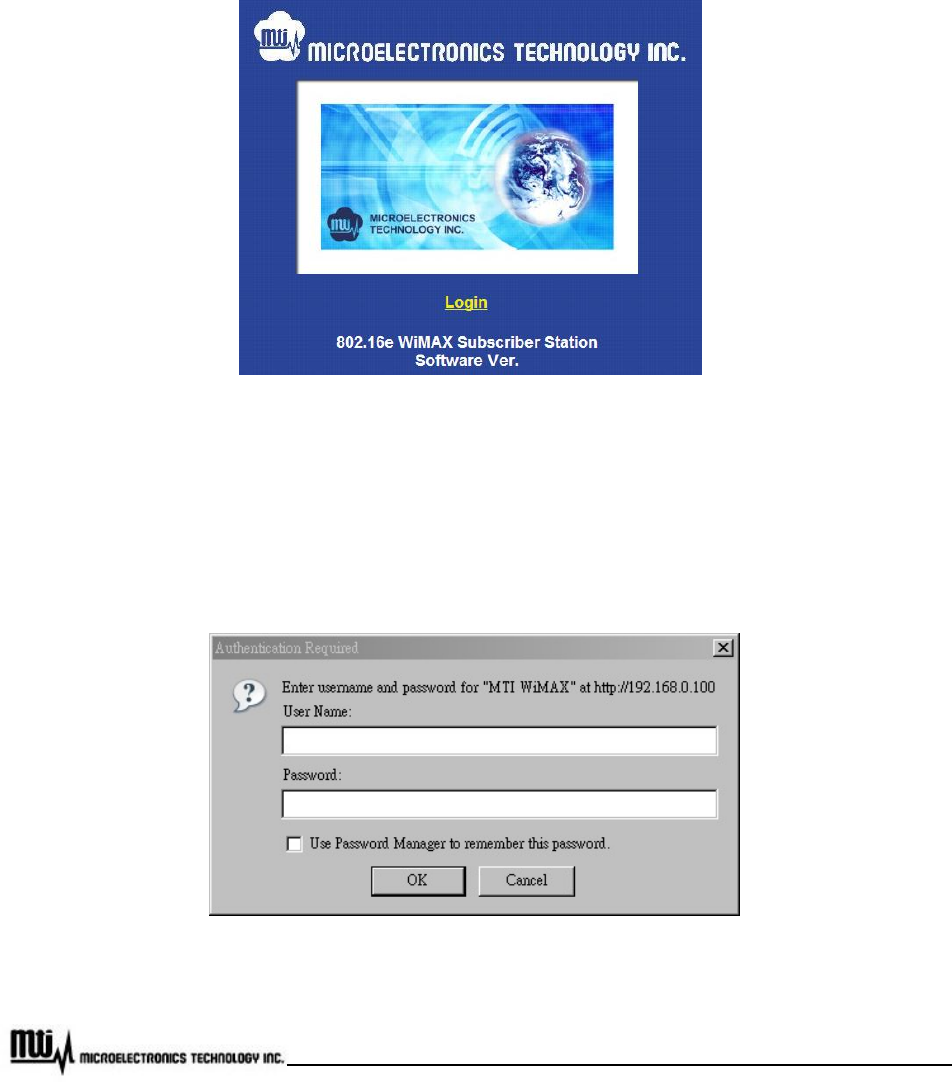
To configure and review status of CPE, please types CPE IP address 192.168.0.100 (default) at URL in
web browser. A greeting page will be shown as Figure 6.
Figure 6 Greeting Page
3.1 Login
Click Login at greeting page, then username and password will be asked, shown as Figure 7.
Figure 7 Login
Page 16 of 35
MTI Proprietary
Please type in username and password as following.
Username: admin
Password: admin
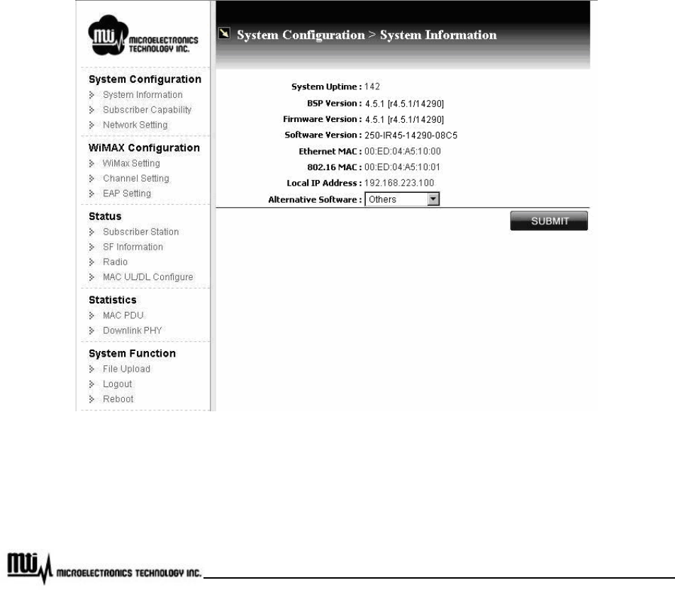
3.2 System Information
System information could be got by clicking “System Information” at CPE web page. In the Figure 8, it
takes 2.5GHz CPE for example, and the Software version here is 250-IR45-14290-08C5.
Figure 8 System Information
Alternative Software: for BS software selection, please click “SUBMIT” button for activation. CPE
uses the alternative image in next boot.
Page 17 of 35
MTI Proprietary
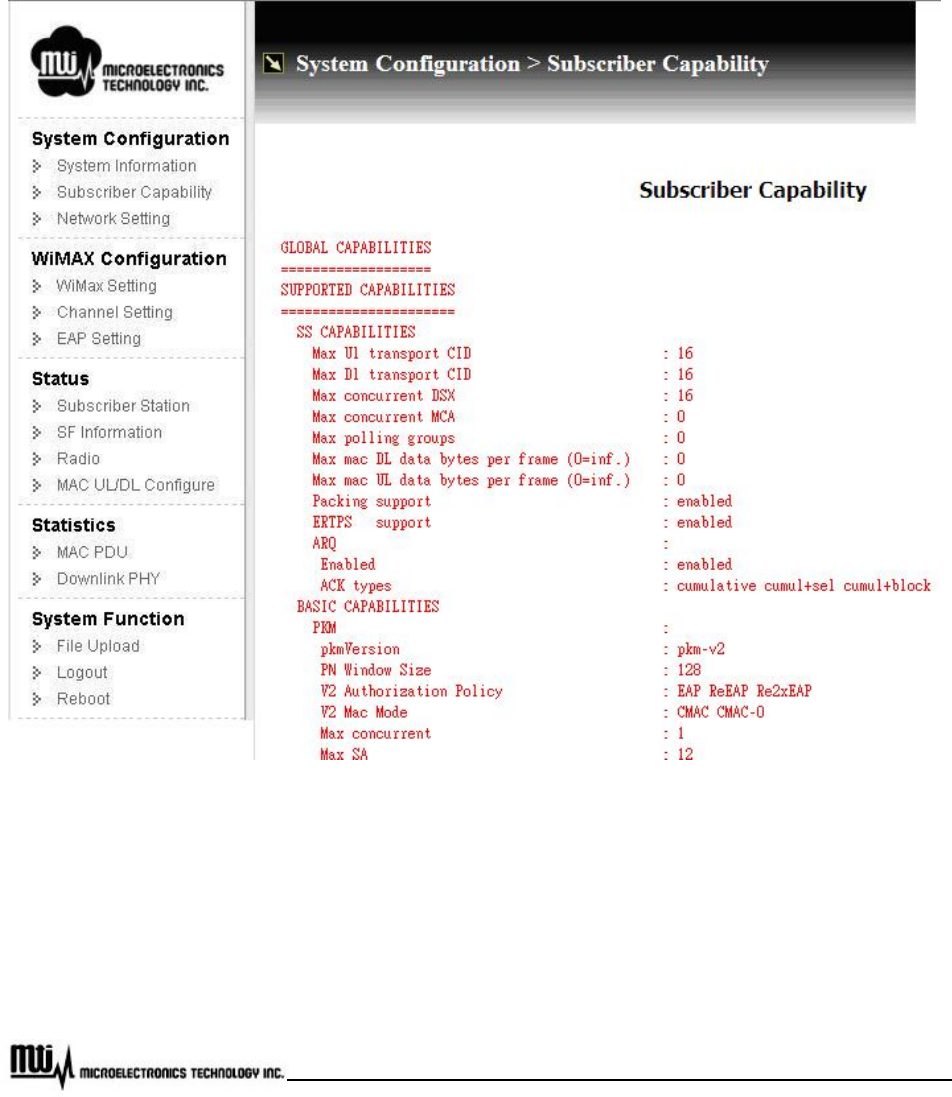
3.3 Subscriber Capability
By clicking “Subscriber Capability” at CPE web page, subscriber capability information will be shown as
Figure 9, including supported capabilities and configured capabilities information.
Figure 9 Subscriber Capability
Page 18 of 35
MTI Proprietary
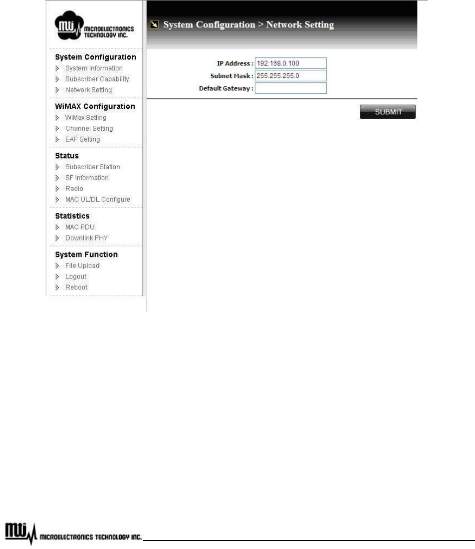
3.4 Network Setting
To configure network, click “Network Setting” at CPE web page, configuration will be shown as Figure 10.
The network configuration will be effective after reboot CPE.
Figure 10 Network Setting
IP Address: Local CPE IP address; default IP address is 192.168.0.100
Subnet Mask: Network subnet mask; default subnet mask is 255.255.255.0
Default Gateway: Default gateway setting
SUBMIT: After modification, please click this button for activation
Page 19 of 35
MTI Proprietary
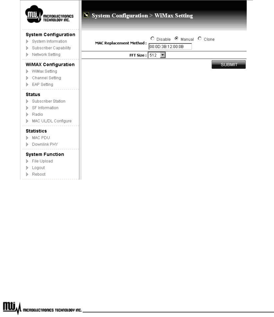
3.5 WiMAX Setting
Click “WiMAX Setting” at CPE web page, customer can setup MAC address and FFT size, shown as
Figure 11.
Figure 11 WiMAX Setting
MAC Address Clone provides three options: Disabled (default), Manual and Clone.
Disable: Default WiMAX 16e MAC address (on label) will be used without replacement MAC
address.
Manual: User must provide a MAC address (ex. PC, Access Point, etc…) for connection with BS,
CPE uses this MAC address instead of default WiMAX 16e MAC address.
Page 20 of 35
MTI Proprietary
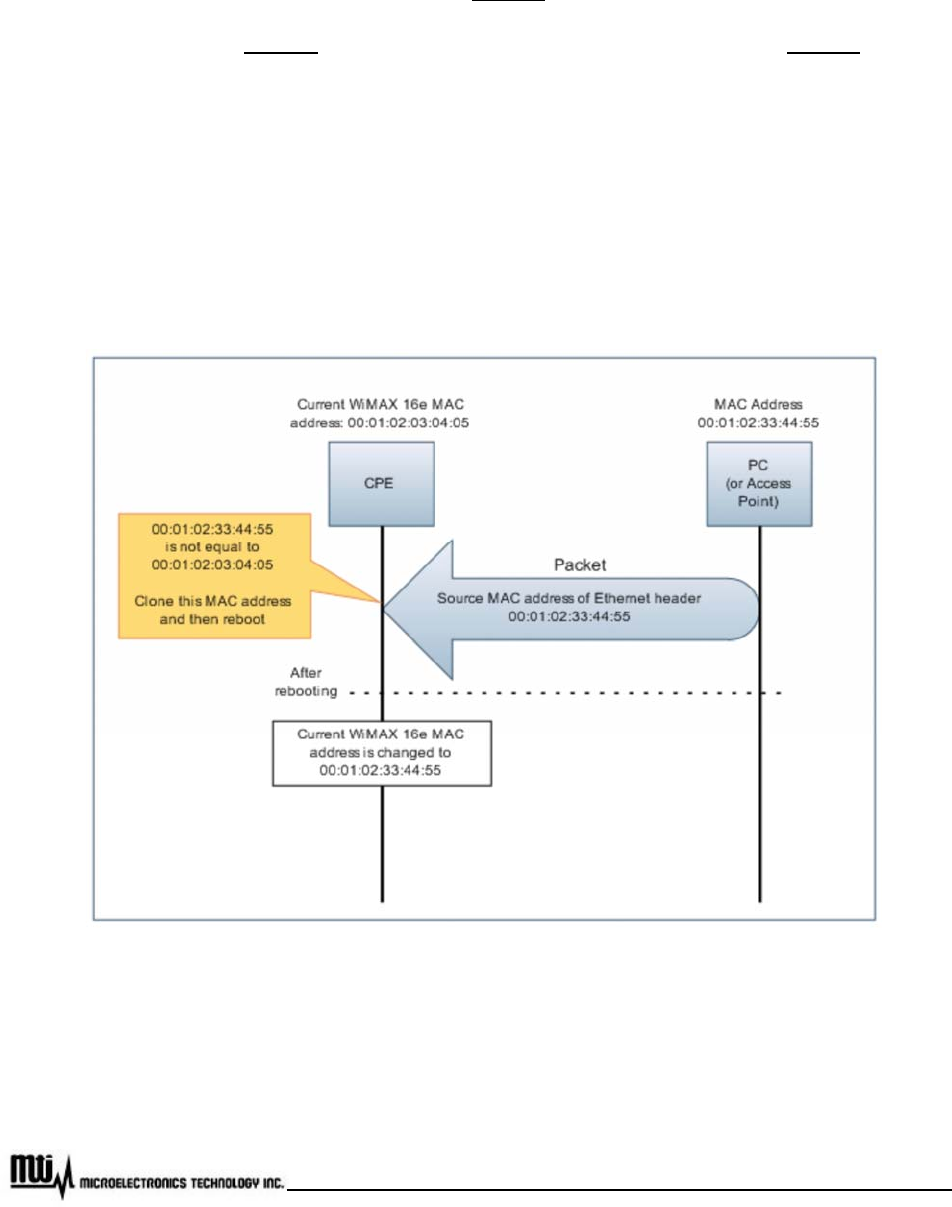
Clone:
z When CPE finds that the link status of Ethernet port is down and up, it will start scanning.
z CPE scans Ethernet port. Once CPE detects the source MAC address of Ethernet header is
not equal to the current WiMAX 16e MAC address, it will capture this MAC address to replace
current one.
z If the captured MAC address is not equal to current one, CPE is going to reboot. After reboot,
it will use the captured MAC address instead of current WiMAX 16e MAC address.
z See Figure 12 for detail information
Figure 12 MAC Address Clone

Page 21 of 35
MTI Proprietary
FFT Size: Before select FFT size, customer has to check with Bandwidth at Channel List
information (please refer to Channel List on Section 3.7 Channel Setup for further information). If
bandwidth is set as 5000KHz, then please select 512 for FFT size. If bandwidth is set as 10000KHz,
then select 1024 for FFT size.
Page 22 of 35
MTI Proprietary
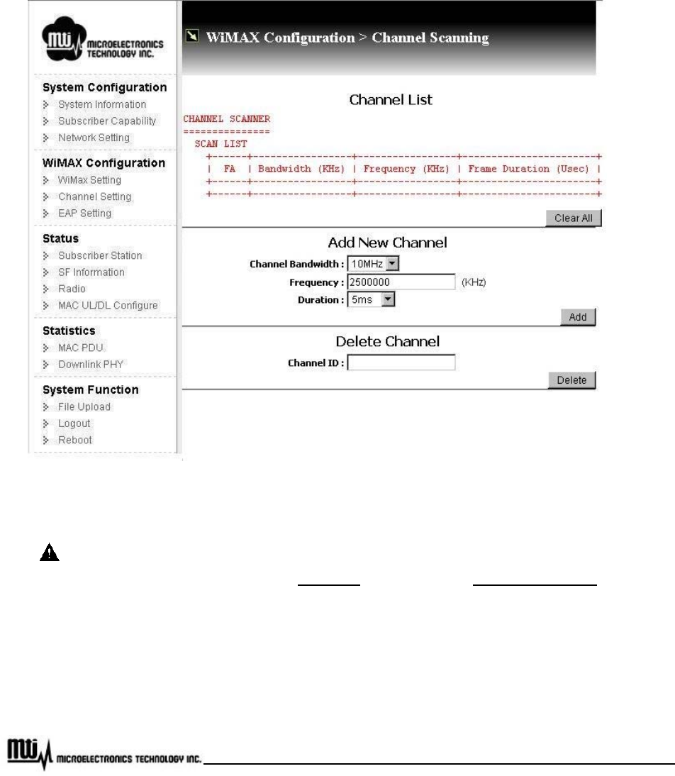
3.6 Channel Setting
To setup WiMAX Channel setup, please click “Channel Setting” at CPE web page, as Figure 13. Here, it
takes 2.5GHz for example.
Figure 13 Channel Setting
Before channel modification (add or delete channels), to stop connection between CPE and
BS is necessary. Please refer to stop/start on Chapter 3.8 Subscriber Station for further
information.
Channel List
z Channel Scanner: All setting channel information will be display here, including bandwidth
(KHz), Frequency (KHz), and frame duration (ms)

Page 23 of 35
MTI Proprietary
z Clear All: Click this button to delete all channels.
Add New Channel
z Channel Bandwidth: Currently, channel bandwidth only supports 5MHz and 10MHz.
z Frequency: For 3.5 GHz CPE, it Supports frequency range from 3650000 KHz to 3675000
KHz. The unit for this field is “KHz”. For example, if desired frequency is 3.65GHz, then enter
“3650000” in this field.
z Duration: Duration supports 5msec.
z Add: Click this button for adding new channel for the configuration.
After adding new channels, it is necessary to establish connection between CPE
and BS to make new channel work. Please refer to stop/start on chapter 3.8
Subscriber Station for detail information.
Delete Channel
z Channel ID: Channel ID could be found at FA field in Scan List Table.
z Delete: Click this button to delete channel.
Page 24 of 35
MTI Proprietary
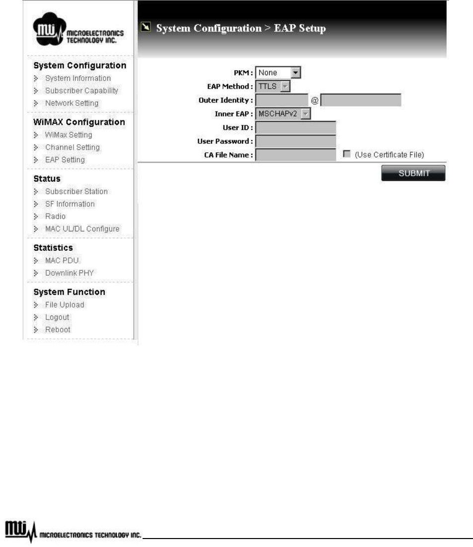
3.7 EAP Setting
By clicking “EAP Setting” at CPE web page, setup Extensible Authentication Protocol (EAP), shown as
Figure 14.
Figure 14 EAP Setting
PKM (Privacy and Key Management): Select “v2 (EAP)” to enable PKM, or select “None” to
disable PKM. Once PKM is disabled, then all the following items will be disabled too.
EAP Method: Supports TTLS
Outer Identity: Enter outer identity. Max length for Identity is 200 characters and for Realm is 48
charcters.

Page 25 of 35
MTI Proprietary
Inner EAP: Support MS CHAP V2 and CHAP.
User ID: Subscriber user ID. Max length is 200 characters.
User Password: Subscriber password. Max length is 200 characters.
CA File Name: Certification File Name. MAX length is 20 characters.
Use Certificate File: If customer would like to perform EAP procedure with CA file, check this
option.
Submit: click this button for activation.
Page 26 of 35
MTI Proprietary
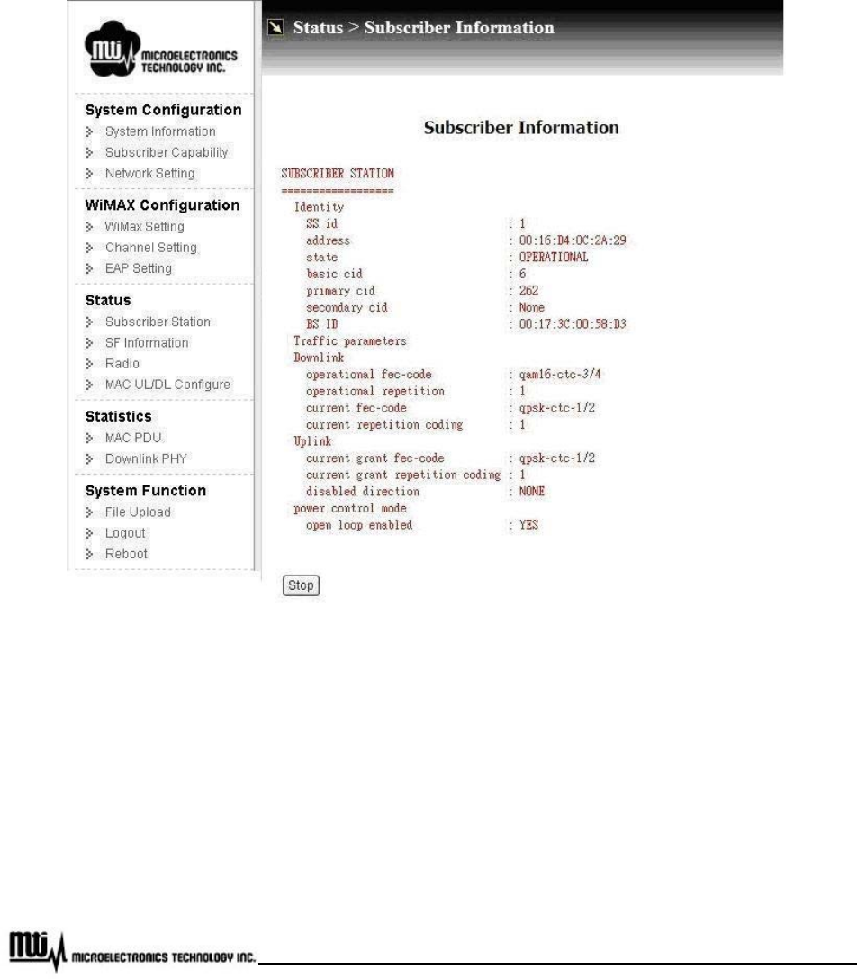
3.8 Subscriber Station
Click “Subscriber Station” to view subscriber station information, and stop / start connection with BS,
shown as Figure 15.
Figure 15 Subscriber Information
Identity
z State: Current connecting state between CPE and BS.
z BS ID: MAC address of connected BS.
Page 27 of 35
MTI Proprietary
Downlink
z Current fec-code: Current assigned modulation scheme.
Stop / Start: Click this button to stop or start connection with BS.
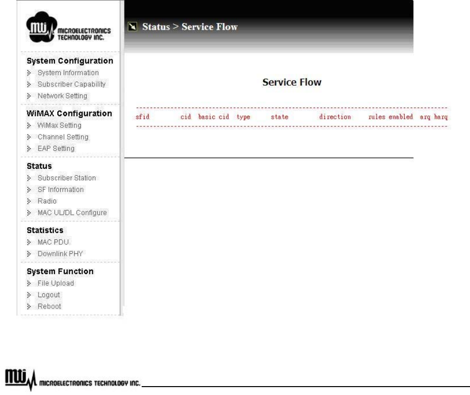
3.9 Service Flow (SF) Information
Click “SF Information” at CPE web page to view service flow information, as Figure 16.
Figure 16 Service Flows Information
Page 28 of 35
MTI Proprietary
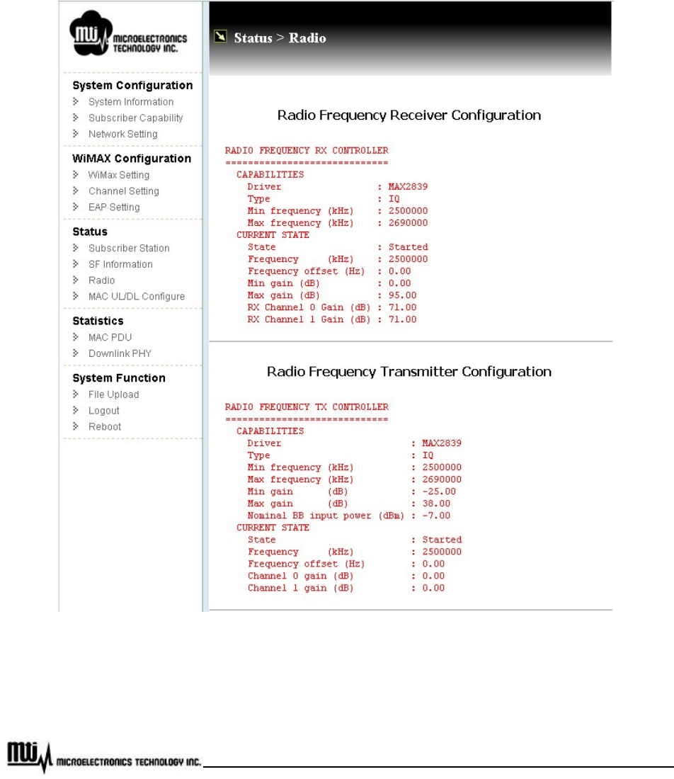
3.10 Radio
Click “Radio” at CPE web page to view radio information, which includes radio frequency receiver and
transmitter configuration, shown as Figure 17. Here, it takes 2.5GHz for example, too.
Figure 17 Radio Information
Page 29 of 35
MTI Proprietary
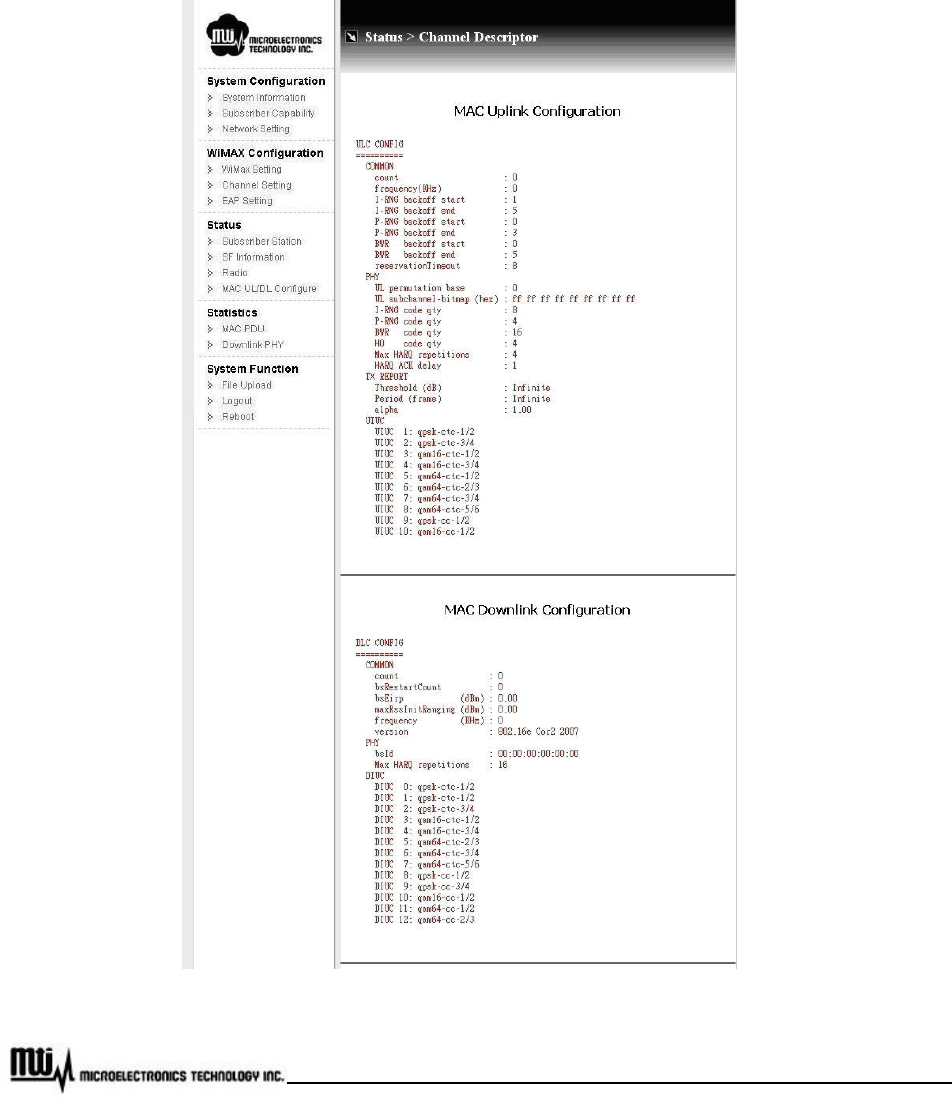
3.11 MAC Uplink / Downlink configuration
By clicking “MAC UL/DL Configure”, customer can get MAC Uplink and Downlink configuration
information, shown as Figure 18.
Figure 18 MAC Uplink / Downlink Configuration
Page 30 of 35
MTI Proprietary
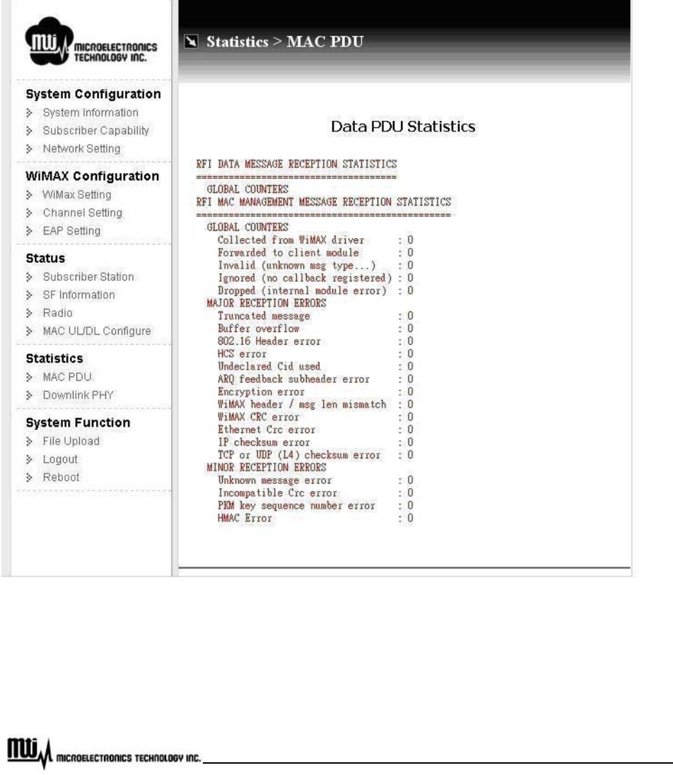
3.12 MAC Packet Data Unit (PDU)
To view MAC Packet Data Unit (PDU), click “MAC PDU” at CPE web page. Customer could view MAC
packet data unit statistics from here, shown as Figure 19.
Figure 19 MAC Packet Data Unit
Page 31 of 35
MTI Proprietary
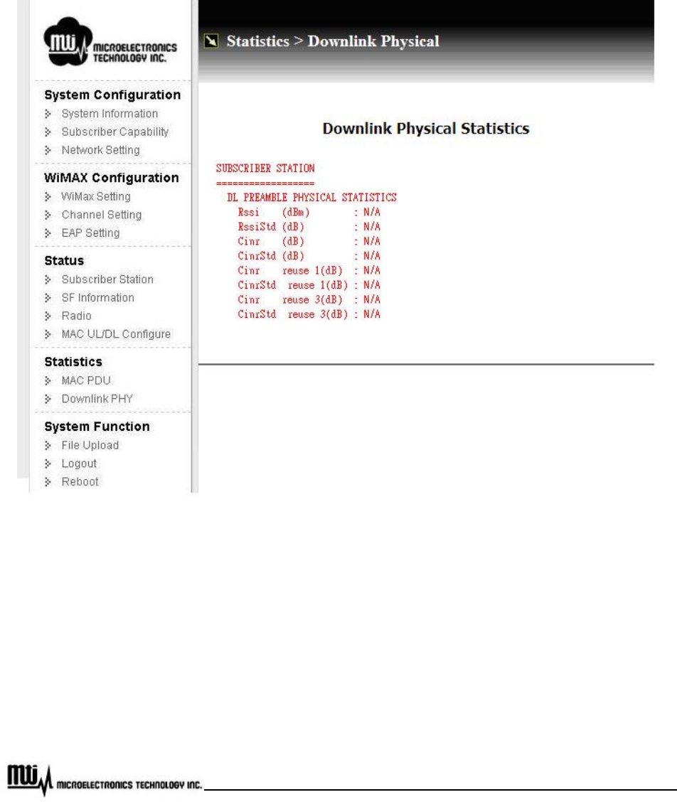
3.13 Downlink Physical (PHY)
Click “Downlink PHY” to view downlink physical statistics, as Figure 20.
Figure 20 Downlink Physical Statistics
Page 32 of 35
MTI Proprietary
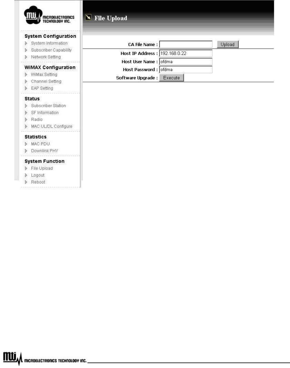
3.14 File Upload
Figure 21 File Upload
3.14.1 Software Upgrade
The CPE provides software upgrade function to upgrade software image or BSP via FTP. The software
upgrade feature could be seen by clicking “File Upload” at CPE web page. The upgrade procedure is as
below.
Before upgrading the software, it is necessary to install FTP server application software on PC. If
customer doesn't have any FTP server application software, please connect to the following address
to download free Filezilla FTP server application software.

Page 33 of 35
MTI Proprietary
http://filezilla-project.org/
After installed the FTP server application on PC, customer needs to add the user name and
password on FTP server. In the Figure 22, it sets "ofdma" as both user name and password for
example. Customer could assign the desired username and password for them. Please note MAX
length for Username and Host password are 15 characters.
After assigned user name and password, please create a FTP directory (Ex.: C:\FTP) on FTP server
at PC side.
At PC site, put the new software image or files, which are provided from CPE vendor, on the FTP
directory (Ex.: C:\FTP) set as previous step.
Click “File Upload” at CPE web page, and enter Host IP Address, Host Username and Host
Password based on the FTP Server setting. Host IP is the IP address of PC and it would be
obtained by key-in “ipconfig/all” at commend window which is executed from Start-> Programs->
Accessories-> Command Prompt on PC. Then IP address of PC could be found at “Ethernet
Adapter Network” portion. Host Username and Host Password are what customer set in previous
steps. (In the example, it uses “ofdma” for both username and password.)
Press “Execute” to perform upgrading procedure. The progress will take 5 ~ 10 minutes depended on
how many files upgraded.
3.14.2 Upload Certification File
System provides the CA file upload via FTP. This feature could be seen by clicking “File Upload” at CPE
web page. The upgrade procedure is as below.
Before upload Certification File, please refer to section 3.15.1 for FTP server setup.
Put the CA file on the FTP directory.
Click “File Upload” at CPE web page, and then enter Host IP Address, Host Username and Host
Password based on the FTP Server.

Page 34 of 35
MTI Proprietary
Press “Upload” to perform upload procedure.
Click “EAP Setting” at CPE web page, and change CA File Name. If customer would like to perform
EAP procedure with CA file, check this option.

Page 35 of 35
MTI Proprietary
3.15 Logout
Click “Logout” in the CPE web page to logout the web page. After logout, web page is re-directed to home
page.
3.16 Reboot
To reboot CPE, please click “Reboot” at CPE web page.