Microhard Systems 01P6 900 MHz Spead Spectrum Module User Manual MHX920Emanua
Microhard Systems Inc 900 MHz Spead Spectrum Module MHX920Emanua
UserManual.wiki
>
Microhard Systems
>
01P6 User Manual
User manual
Navigation menu
Upload a User Manual
Namespaces
Wiki Guide
HTML
PDF
Info
Views
User Manual
Discussion / Help
Navigation
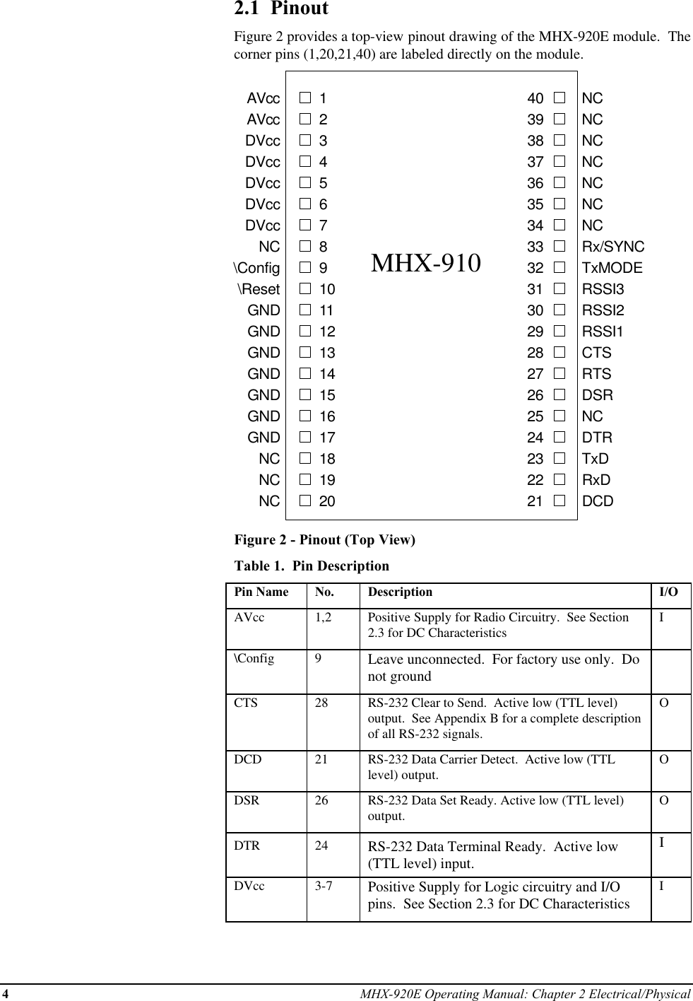
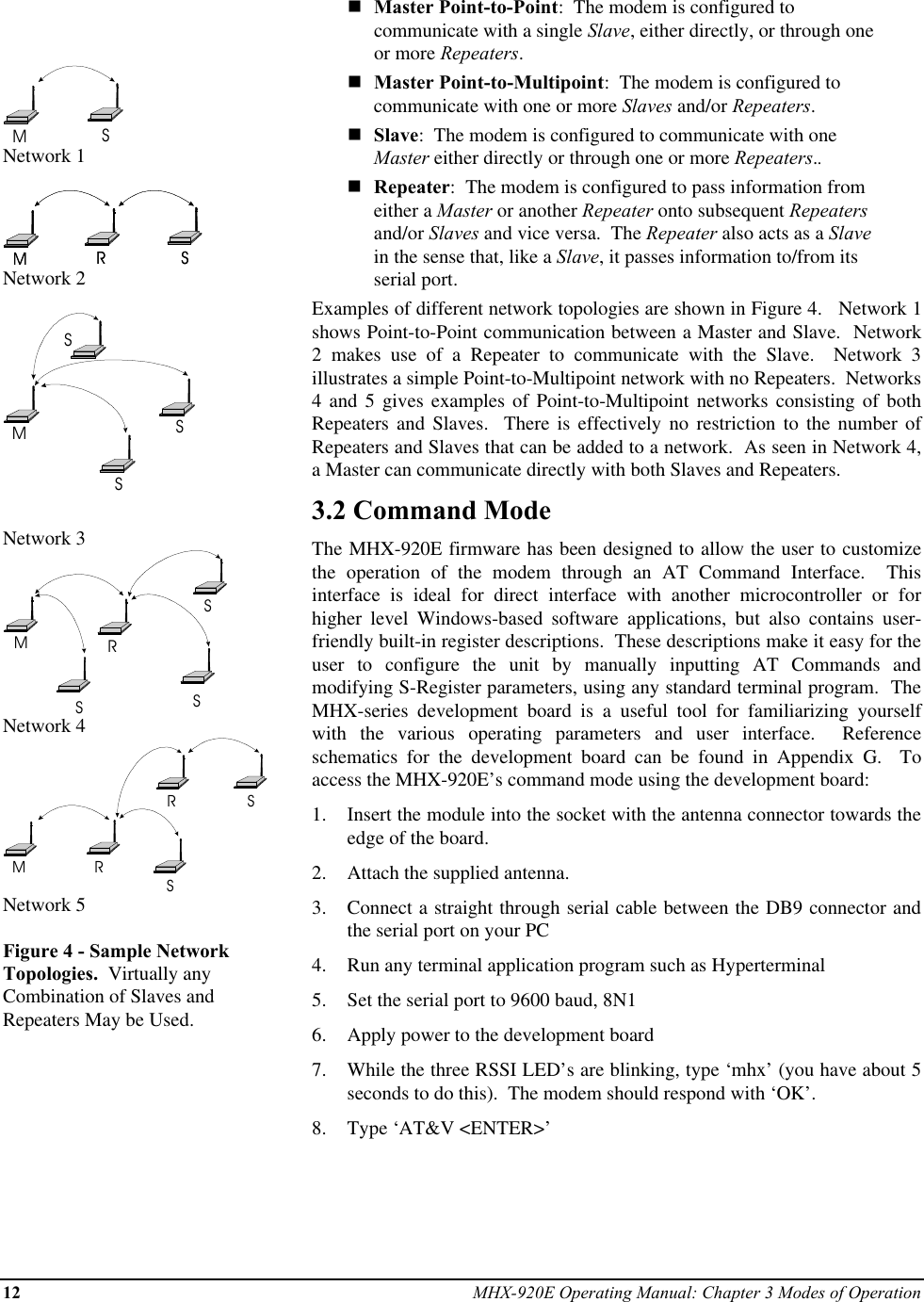
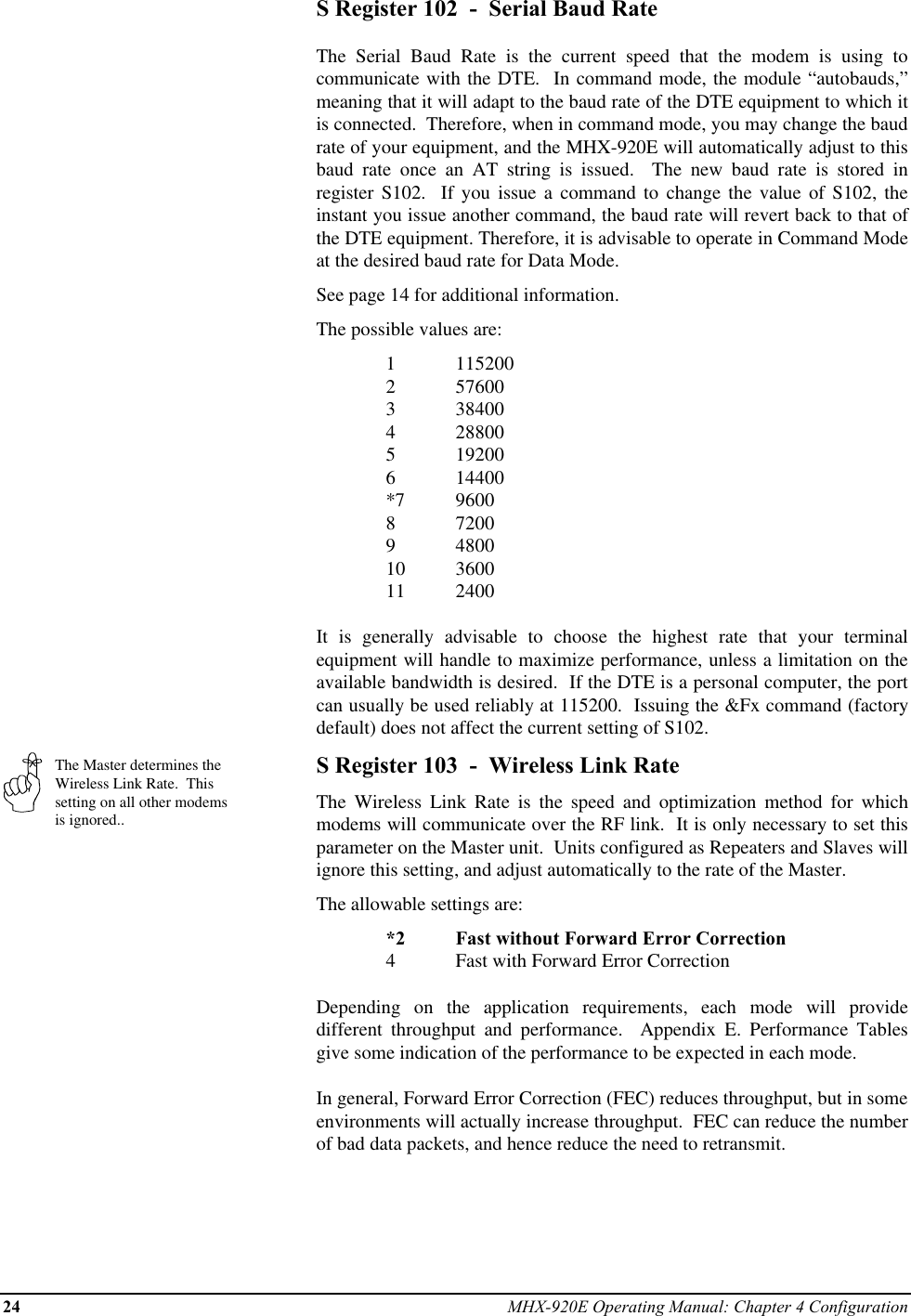
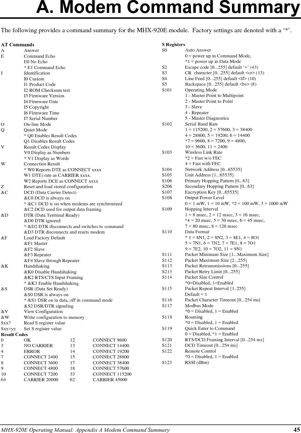
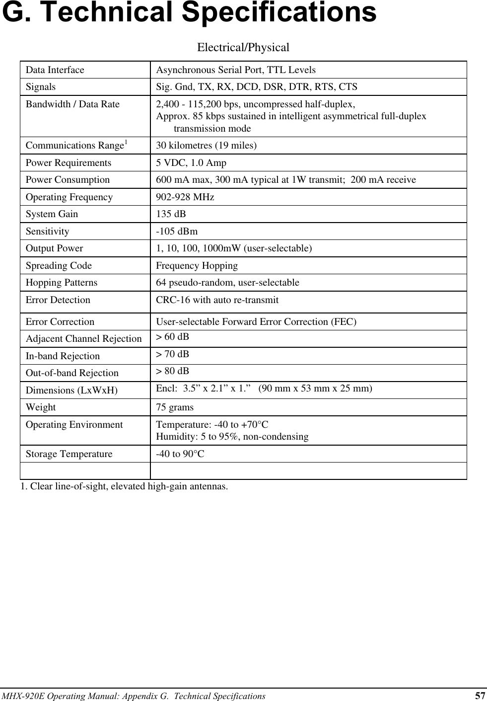
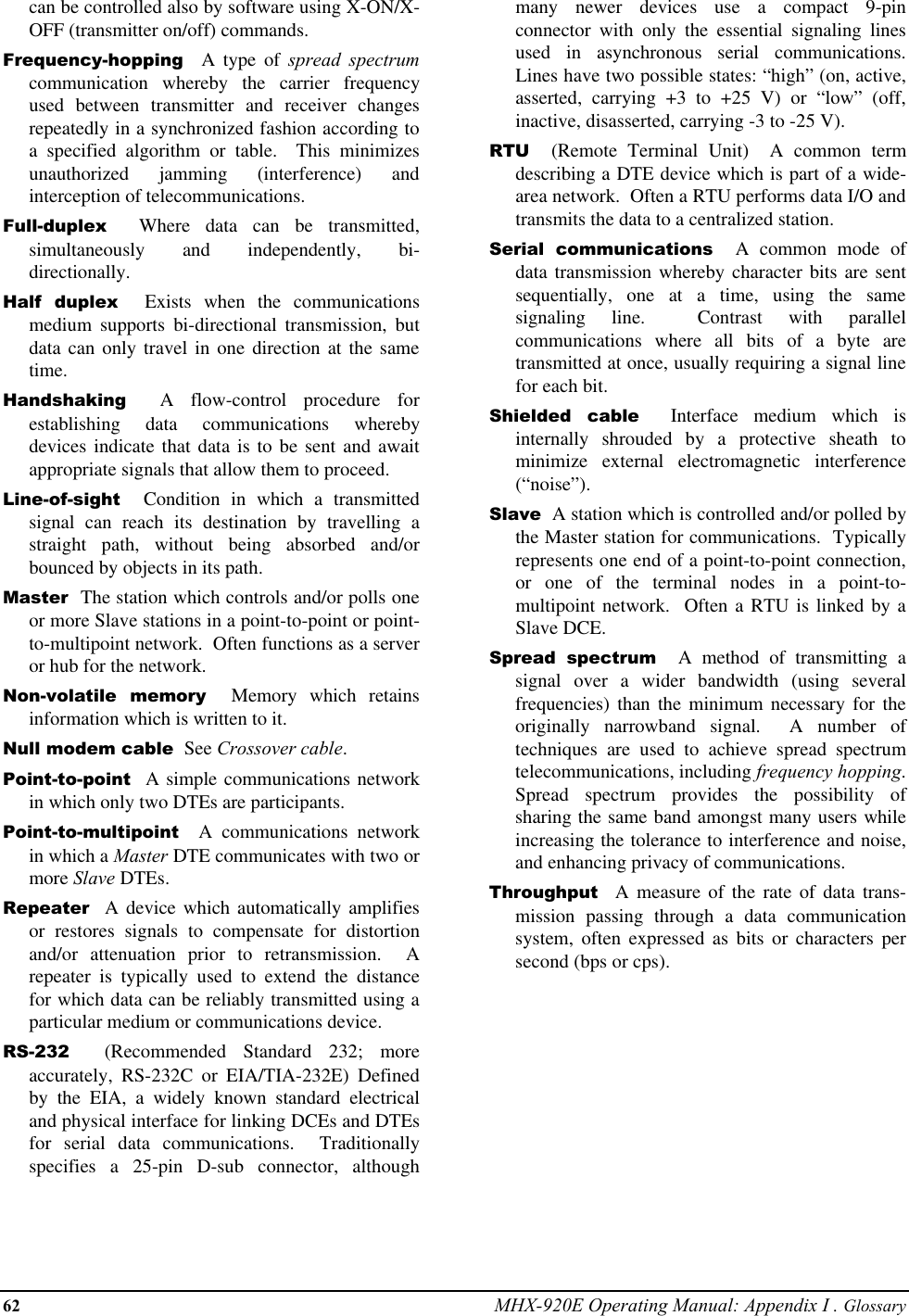
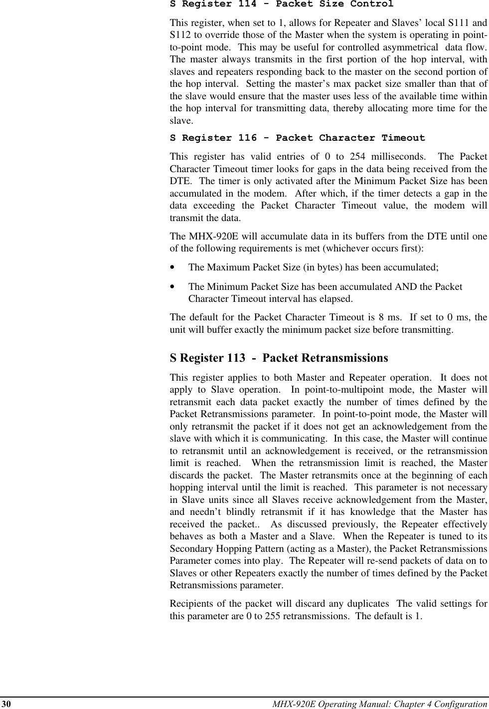
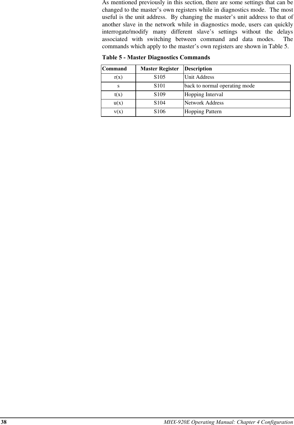
![MHX-920E Operating Manual: Chapter 4 Configuration 25Select a Network Addressand assign it to all unitswhich will be included in thenetwork.Warning: Microhard Systemsstrongly recommends changing theNetwork Address to a valuedifferent than the factory defaultbefore deploying the network.Use the same Unit Addresson both units for point-to-point mode. In multipointmode, set each Slave andRepeater to a different UnitAddress.Valid Unit Addresses are 1to 65535.S Register 104 - Network AddressThe Network Address defines the membership to which individual units canbe a part of. By establishing a network under a common Network Address,the network can be isolated from any other concurrently operating network.As well, the Network Address provides a measure of privacy and security.Only those units which are members of the network will participate in thecommunications interchange. Valid values for the Network Address rangefrom 0 to 65535, inclusive.To enhance privacy and reliability of communications where multiplenetworks may operate concurrently in close proximity, it is suggested that anatypical value be chosen – perhaps something meaningful yet not easilyselected by chance or coincidence.Default is 1.S Register 105 - Unit AddressIn point-to-point operation, the Unit Address on both the Master and Slave(or Repeater) units must be the same. In a multipoint system, the UnitAddress uniquely identifies each Slave and Repeater from one another.Each unit in a multipoint system must have a unique Unit Address rangingfrom 1 to 65535. Do not use 0 as a Unit Address, and do not use a UnitAddress more than once within the same Network. This is required becausethe Master must be able to acknowledge each unit individually, based on theUnit Address.S Register 106 - Primary Hopping PatternS Register 206 - Secondary Hopping PatternSince the MHX-920E is a frequency-hopping modem, the carrier frequencychanges periodically according to one of 64 pseudo-random patterns,defined by the Primary and Secondary Hopping Patterns. Valid entries foreach are 0 through 63. Patterns 0 through 61 are pre-programmed, withdetails provided in Appendix F. Patterns 58 through 63 are user-editablepatterns. See Appendix F for details.The concept of Primary and Secondary Hopping Patterns was introduced inthe discussion of S Register 101 (Operating Mode).Using the designations M[a,] Rx[a,b] and Sx[a] where:- M indicates Master;- R indicates Repeater;- S indicates Slave;- x is the Unit Address;- a is the primary hopping pattern; and,- b is the secondary hopping pattern;](https://usermanual.wiki/Microhard-Systems/01P6/User-Guide-139159-Page-29.png)
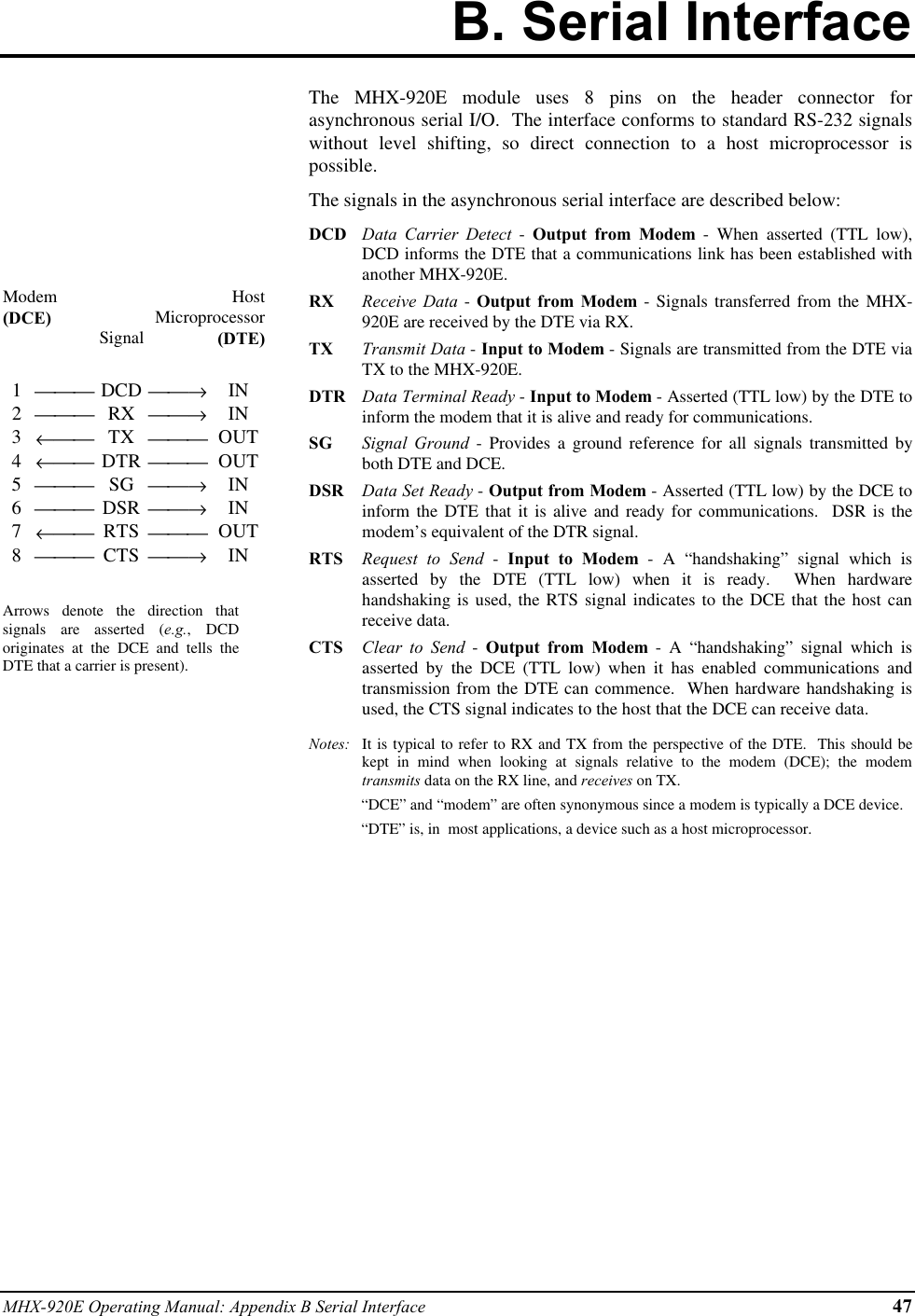
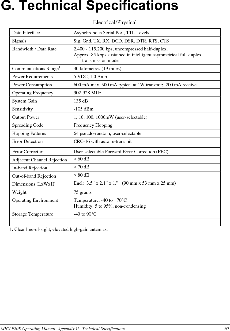
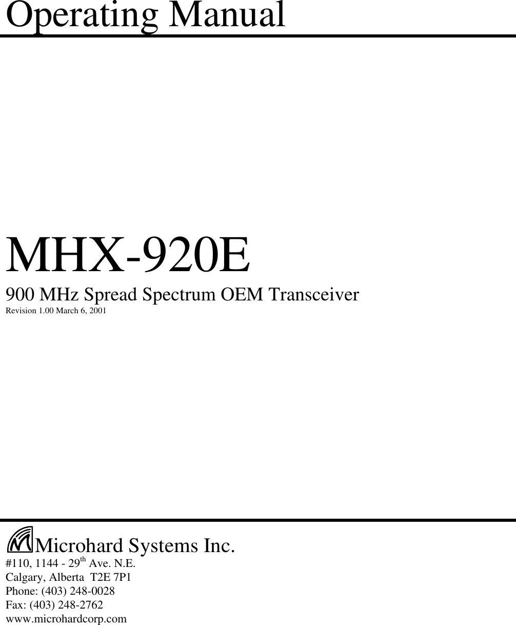
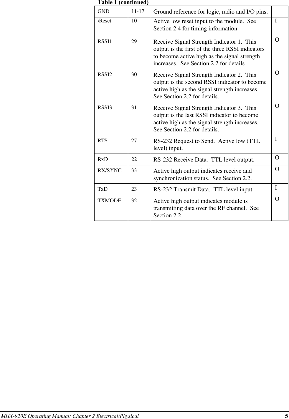
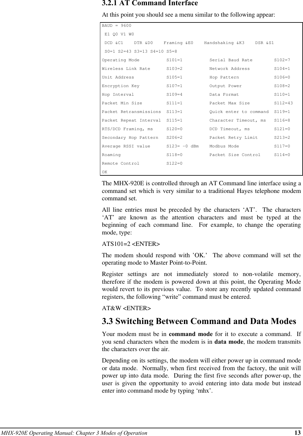
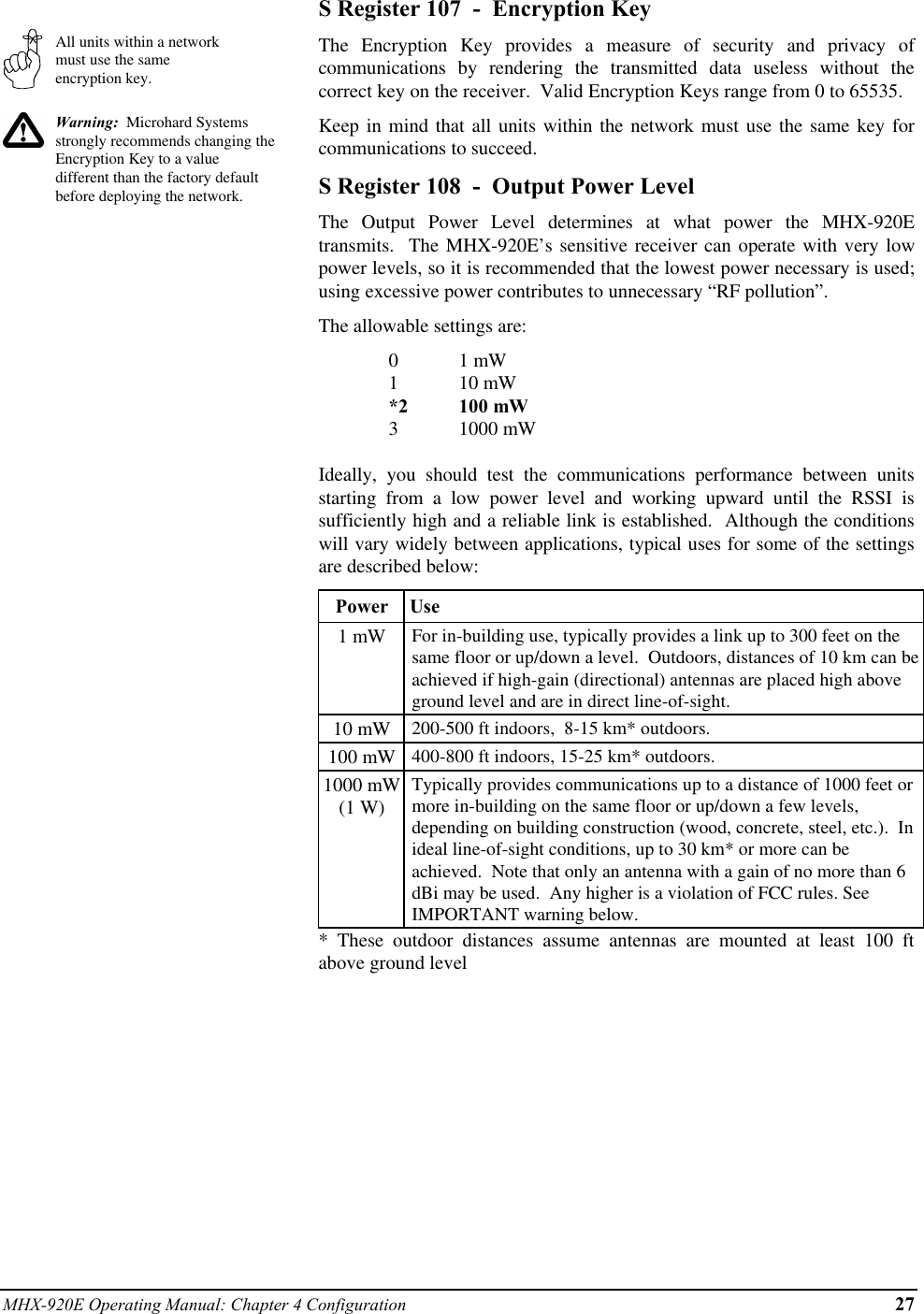
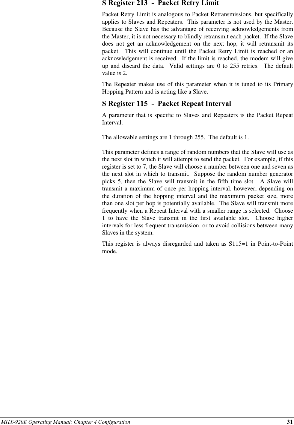
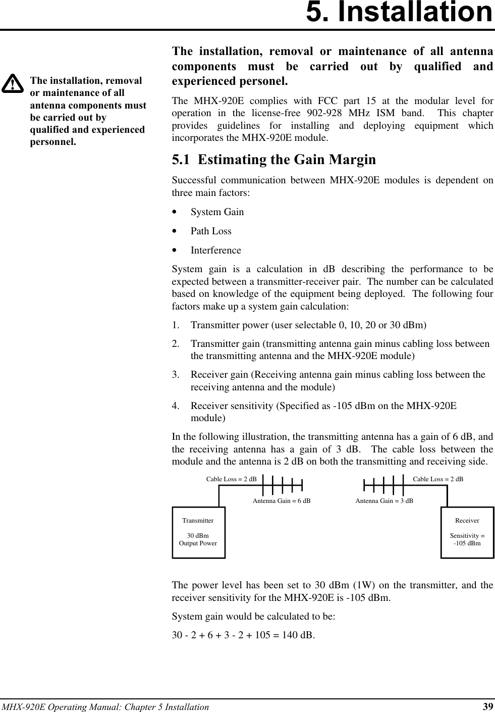
![26 MHX-920E Operating Manual: Chapter 4 ConfigurationMaster SlaveMaster Repeater SlaveMaster Repeater1 Repeater2 SlaveSlaves and Masters do notuse Secondary HoppingPatternsRemember to assign aunique Unit Address (1 to65535) to each unit in thesystemthe following diagrams illustrate the methodology for deploying simple tocomplicated networks:M[1] ←→ S1[1]M[1] ←→ R1[1,2] ←→ S2[2]M[1] ←→ R1[1,2] ←→ R2[2,3] ←→ S3[3]M[1] ←→ R1[1,2] ←→ R2[2,3] ←→ R3[3,4] ←→ S4[4]It is reasonable to consider a Repeater as being both a Slave and a Master,alternating between Primary and Secondary Hopping Patterns as the unitchanges channel. Consider R1 in the illustration below. Whencommunicating with the Master, R1 is acting like a Slave on PrimaryHopping Pattern 1. When communicating with R2 and S4, R1 is acting likea Master on Secondary Hopping Pattern 2. If multiple Repeaters are used,they should have different Secondary Hopping Patterns:←→ R1[1,2] ←→ R2[2,5] ←→ S3[5]M[1] ←→ S4[2]←→ R5[1,3] ←→ R6[3,6] ←→ S7[6]←→ R8[1,4] ←→ S9[4]Note that all units have a unique Unit Address.Networks of any complexity can be created by linking multiple Repeatersand Slaves:←→ R1[1,2] ←→ S2[2]←→ S3[2]←→ ←→ R5[3,6] ←→ S6[6]M[1] R4[1,3] ←→ S7[6]←→ R8[3,7] ←→ R9[7,8] ←→ S10[8]←→ S11[1]←→ S12[1]With a limitation of 64 hopping patterns, one might suspect that there is alimitation to the number of repeaters in a system. However, if the units arefar enough away from one another, hopping patterns may be reused indifferent sections of the network, without causing interference.](https://usermanual.wiki/Microhard-Systems/01P6/User-Guide-139159-Page-30.png)
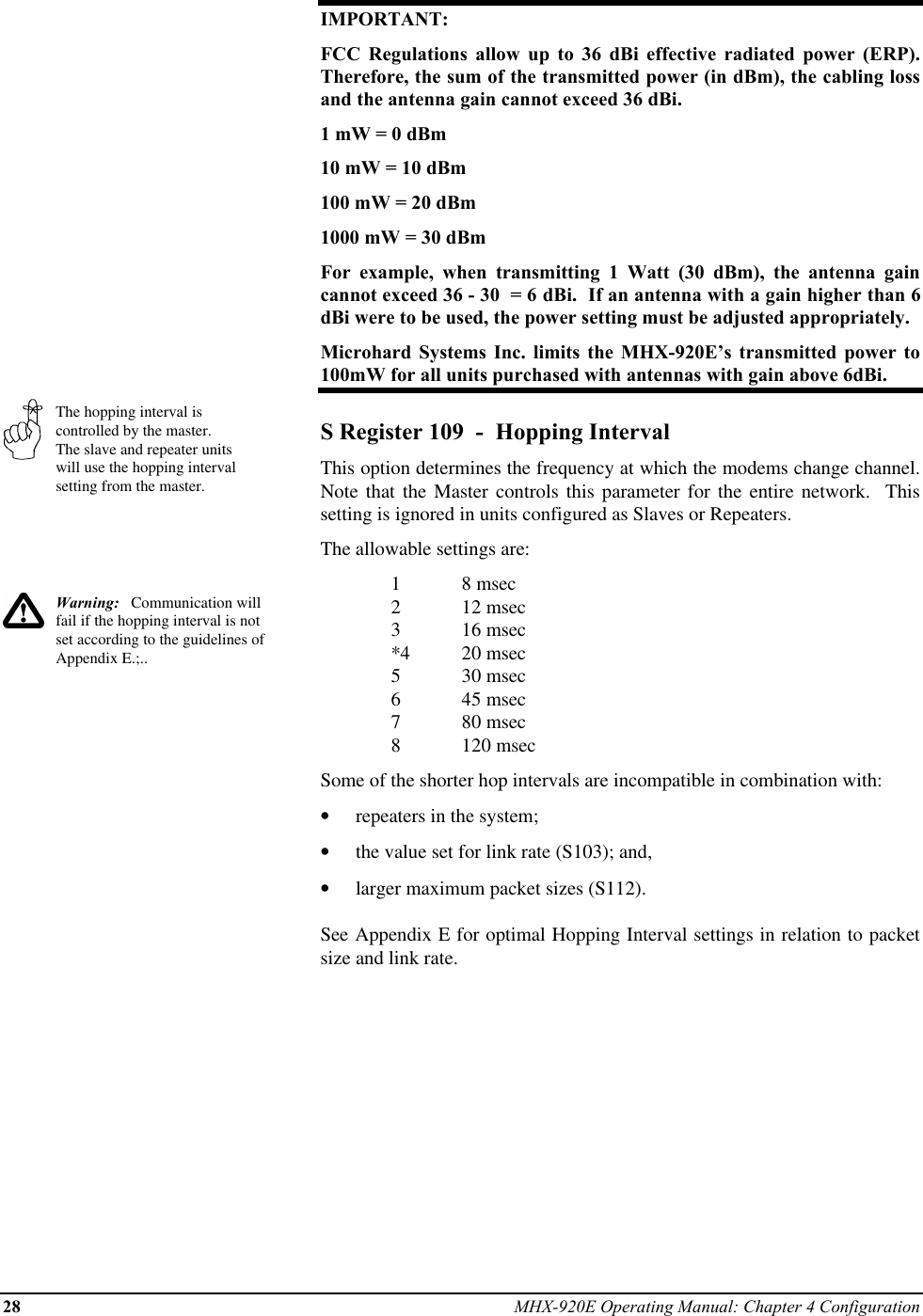
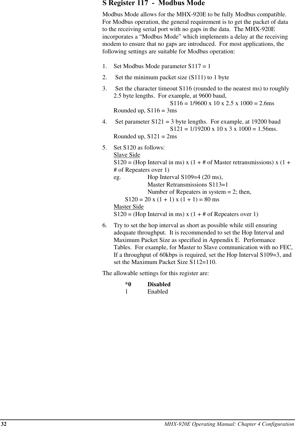
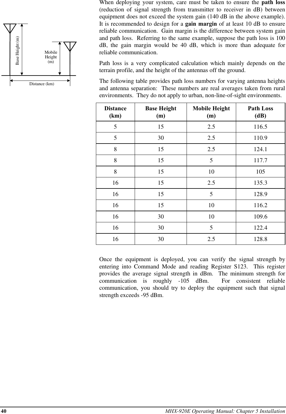

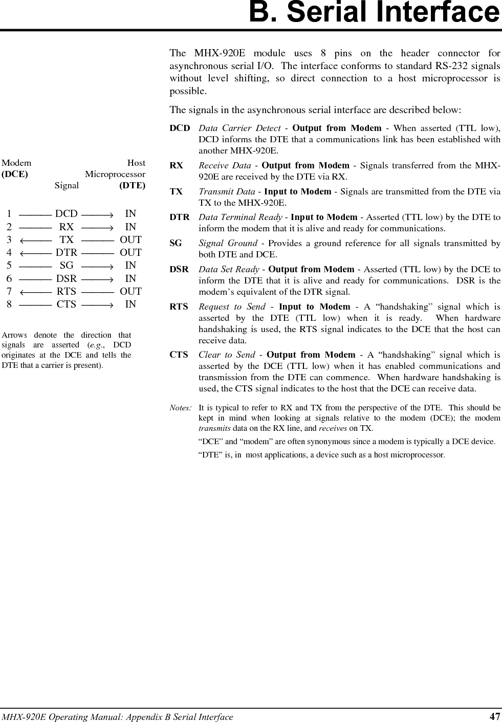
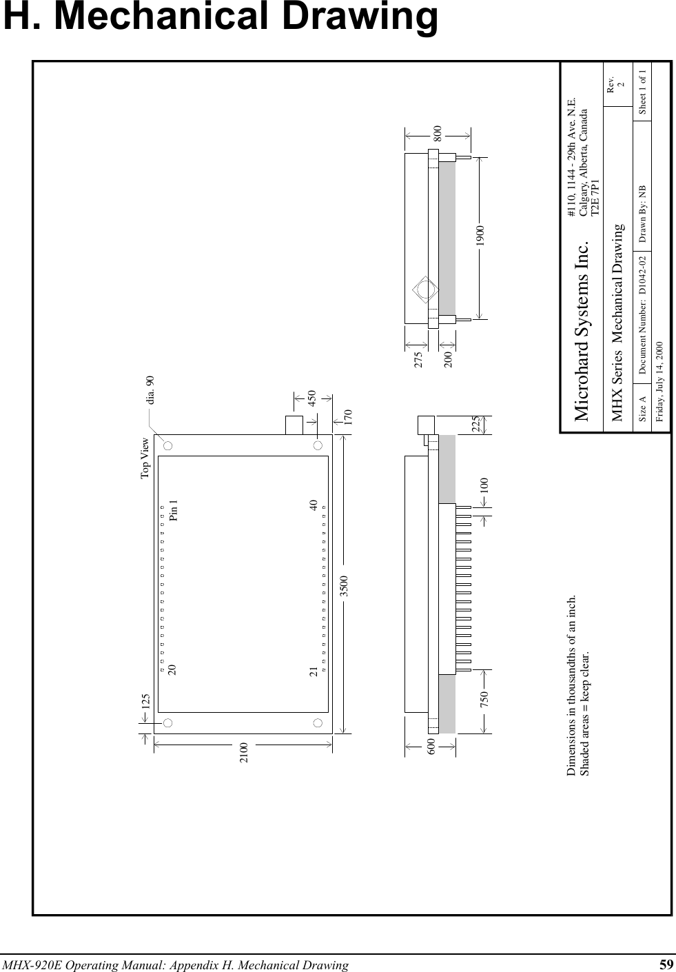
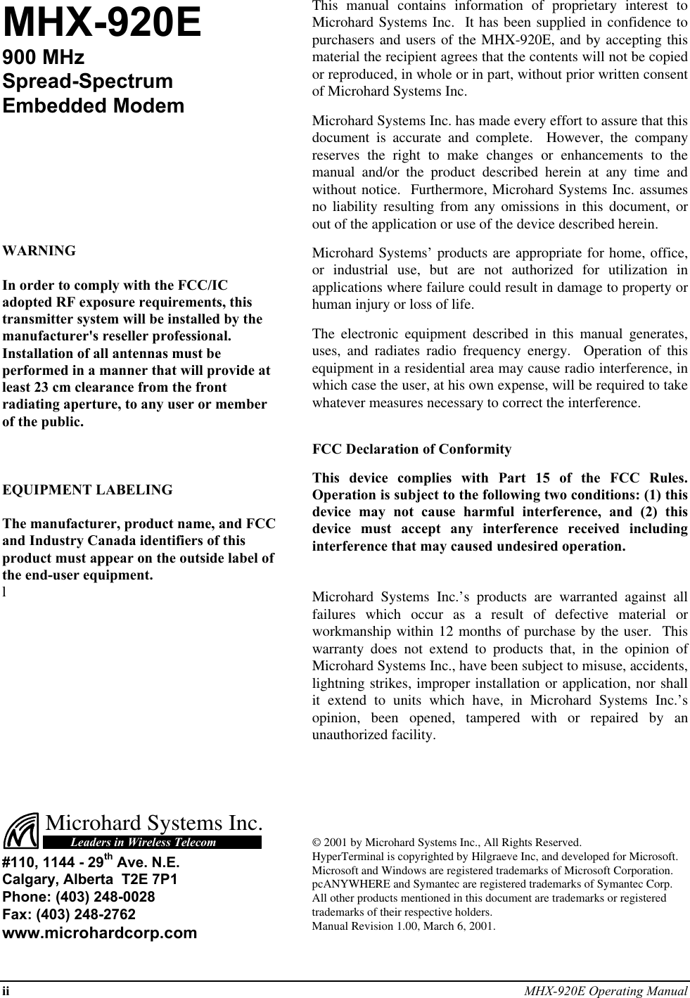
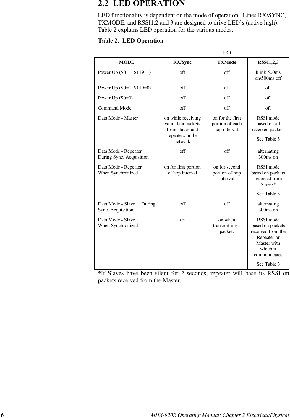
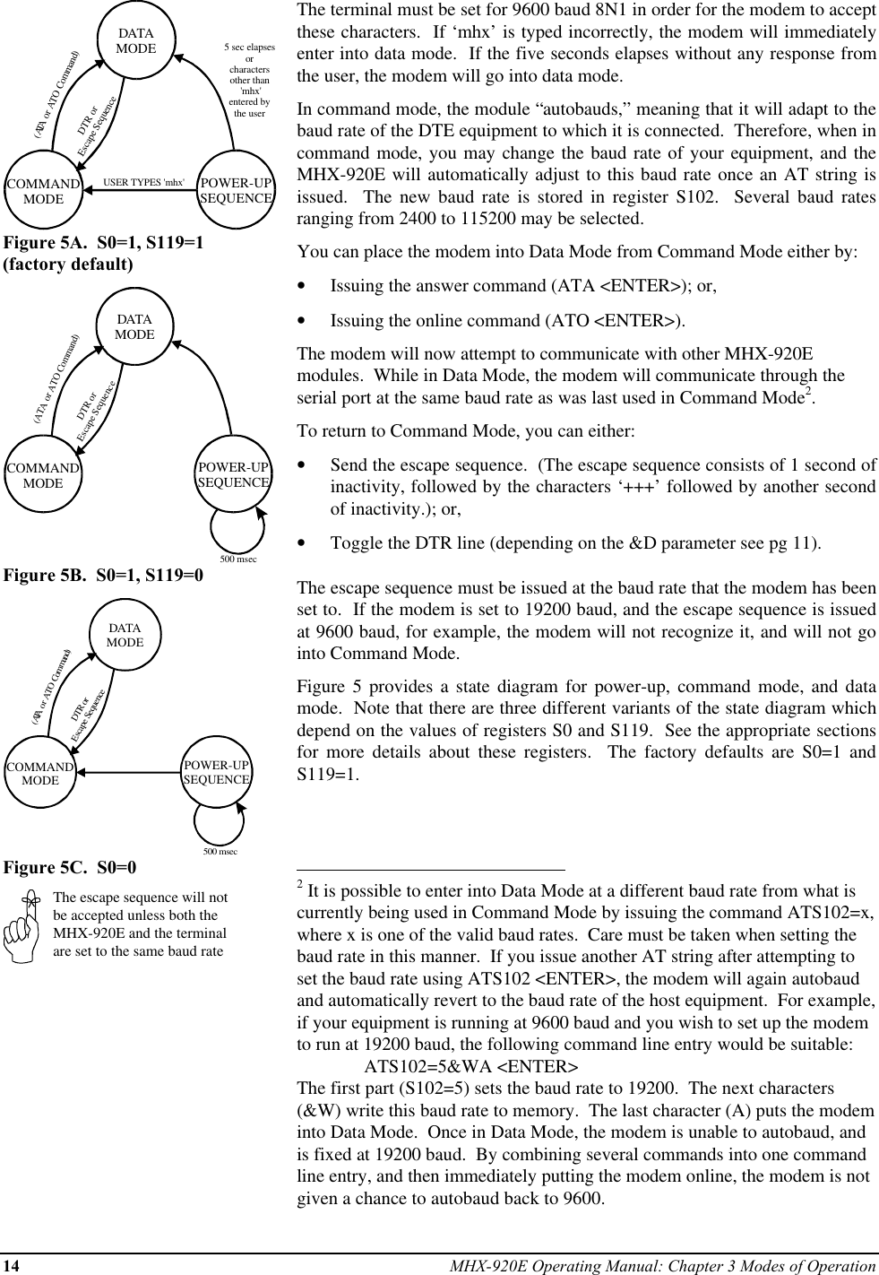
![MHX-920E Operating Manual: Appendix A Modem Command Summary 45A. Modem Command SummaryThe following provides a command summary for the MHX-920E module. Factory settings are denoted with a ‘*’.AT CommandsAAnswerECommand EchoE0 No Echo* E1 Command EchoIIdentificationI0 CustomI1 Product CodeI2 ROM Checksum testI3 Firmware VersionI4 Firmware DateI5 CopyrightI6 Firmware TimeI7 Serial NumberOOn-line ModeQQuiet Mode* Q0 Enables Result CodesQ1 Disables Result CodesVResult Codes DisplayV0 Display as Numbers* V1 Display as WordsWConnection Result* W0 Reports DTE as CONNECT xxxxW1 DTE) rate as CARRIER xxxx.W2 Reports DCE as CONNECT xxxxZReset and load stored configuration&C DCD (Data Carrier Detect)&C0 DCD is always on* &C1 DCD is on when modems are synchronized&C2 DCD used for output data framing&D DTR (Data Terminal Ready)&D0 DTR ignored* &D2 DTR disconnects and switches to command&D3 DTR disconnects and resets modem&F Load Factory Default&F1 Master&F2 Slave&F3 Repeater&F4 Slave through Repeater&K Handshaking&K0 Disable Handshaking&K2 RTS/CTS Input Framing* &K3 Enable Handshaking&S DSR (Data Set Ready)&S0 DSR is always on* &S1 DSR on in data, off in command mode&S2 DSR/DTR signaling&V View Configuration&W Write configuration to memorySxx? Read S register valueSxx=yy Set S register valueResult Codes0OK 12 CONNECT 96003NO CARRIER 13 CONNECT 144004ERROR 14 CONNECT 192007CONNECT 2400 15 CONNECT 288008CONNECT 3600 17 CONNECT 384009CONNECT 4800 18 CONNECT 5760010 CONNECT 7200 33 CONNECT 11520064 CARRIER 20000 62 CARRIER 45000S RegistersS0 Auto Answer0 = power up in Command Mode,*1 = power up in Data ModeS2 Escape code [0...255] default ‘+’ (43)S3 CR character [0...255] default <cr> (13)S4 Line Feed [0...255] default <lf> (10)S5 Backspace [0...255] default <bs> (8)S101 Operating Mode1 - Master Point to Multipoint2 - Master Point to Point3 - Slave4 - Repeater5 - Master DiagnosticsS102 Serial Baud Rate1 = 115200, 2 = 57600, 3 = 384004 = 28800, 5 = 19200, 6 = 14400*7 = 9600, 8 = 7200, 9 = 4800,10 = 3600, 11 = 2400S103 Wireless Link Rate*2 = Fast w/o FEC4 = Fast with FECS104 Network Address [0...65535]S105 Unit Address [1...65535]S106 Primary Hopping Pattern [0...63]S206 Secondary Hopping Pattern [0...63]S107 Encryption Key [0...65535]S108 Output Power Level0 = 1 mW, 1 = 10 mW, *2 = 100 mW, 3 = 1000 mWS109 Hopping Interval1 = 8 msec, 2 = 12 msec, 3 = 16 msec,*4 = 20 msec, 5 = 30 msec, 6 = 45 msec,7 = 80 msec, 8 = 120 msecS110 Data Format* 1 = 8N1, 2 = 8N2, 3 = 8E1, 4 = 8O15 = 7N1, 6 = 7N2, 7 = 7E1, 8 = 7O19 = 7E2, 10 = 7O2, 11 = 9N1S111 Packet Minimum Size [1...Maximum Size]S112 Packet Maximum Size [2...255]S113 Packet Retransmissions [0...255]S213 Packet Retry Limit [0...255]S114 Packet Size Control*0=Disabled, 1=EnabledS115 Packet Repeat Interval [1..255]Default = 1S116 Packet Character Timeout [0...254 ms]S117 Modbus Mode*0 = Disabled, 1 = EnabledS118 Roaming*0 = Disabled, 1 = EnabledS119 Quick Enter to Command0 = Disabled, *1 = EnabledS120 RTS/DCD Framing Interval [0...254 ms]S121 DCD Timeout [0...254 ms]S122 Remote Control*0 = Disabled, 1 = EnabledS123 RSSI (dBm)](https://usermanual.wiki/Microhard-Systems/01P6/User-Guide-139159-Page-49.png)