Microhard Systems 07P22 MHX2420-2400MHz OEM FREQUENCY HOPPING MODULE User Manual MHX2420manualREV0 30 FCC
Microhard Systems Inc MHX2420-2400MHz OEM FREQUENCY HOPPING MODULE MHX2420manualREV0 30 FCC
UserManual.wiki
>
Microhard Systems
>
07P22 User Manual
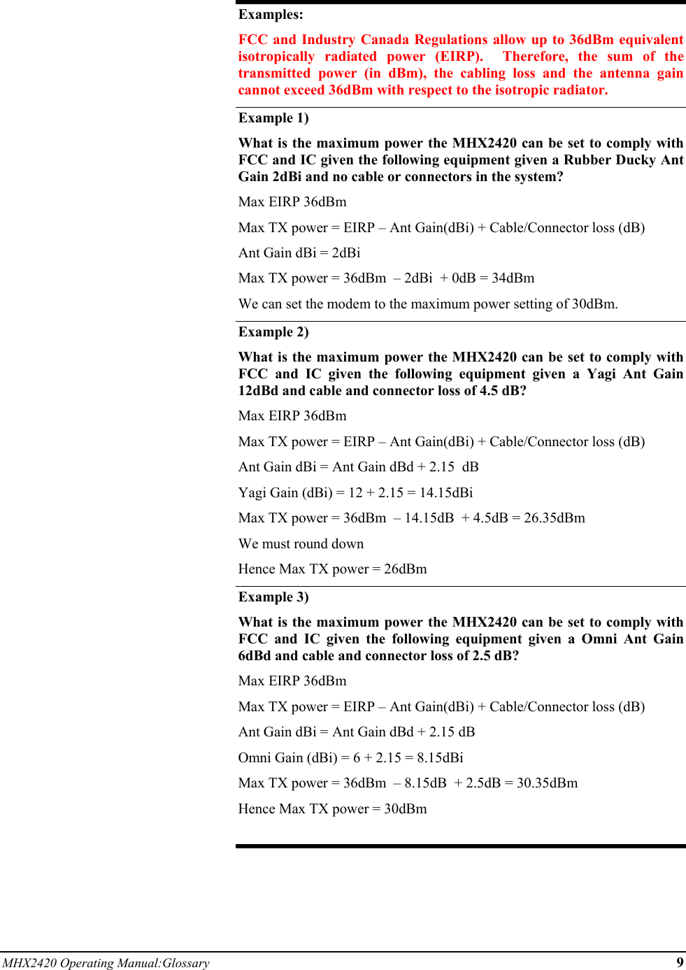
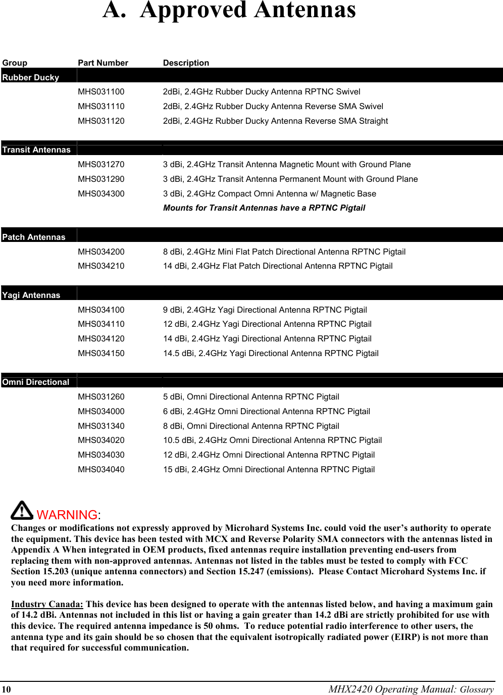
USERS MANUAL
Navigation menu
Upload a User Manual
Namespaces
Wiki Guide
HTML
PDF
Info
Views
User Manual
Discussion / Help
Navigation