Microhard Systems 99P2 User Manual MHX 900 Manual03
Microhard Systems Inc MHX 900 Manual03
UserManual.wiki
>
Microhard Systems
>
99P2 User Manual
MHX 900 User Manual
Navigation menu
Upload a User Manual
Namespaces
Wiki Guide
HTML
PDF
Info
Views
User Manual
Discussion / Help
Navigation

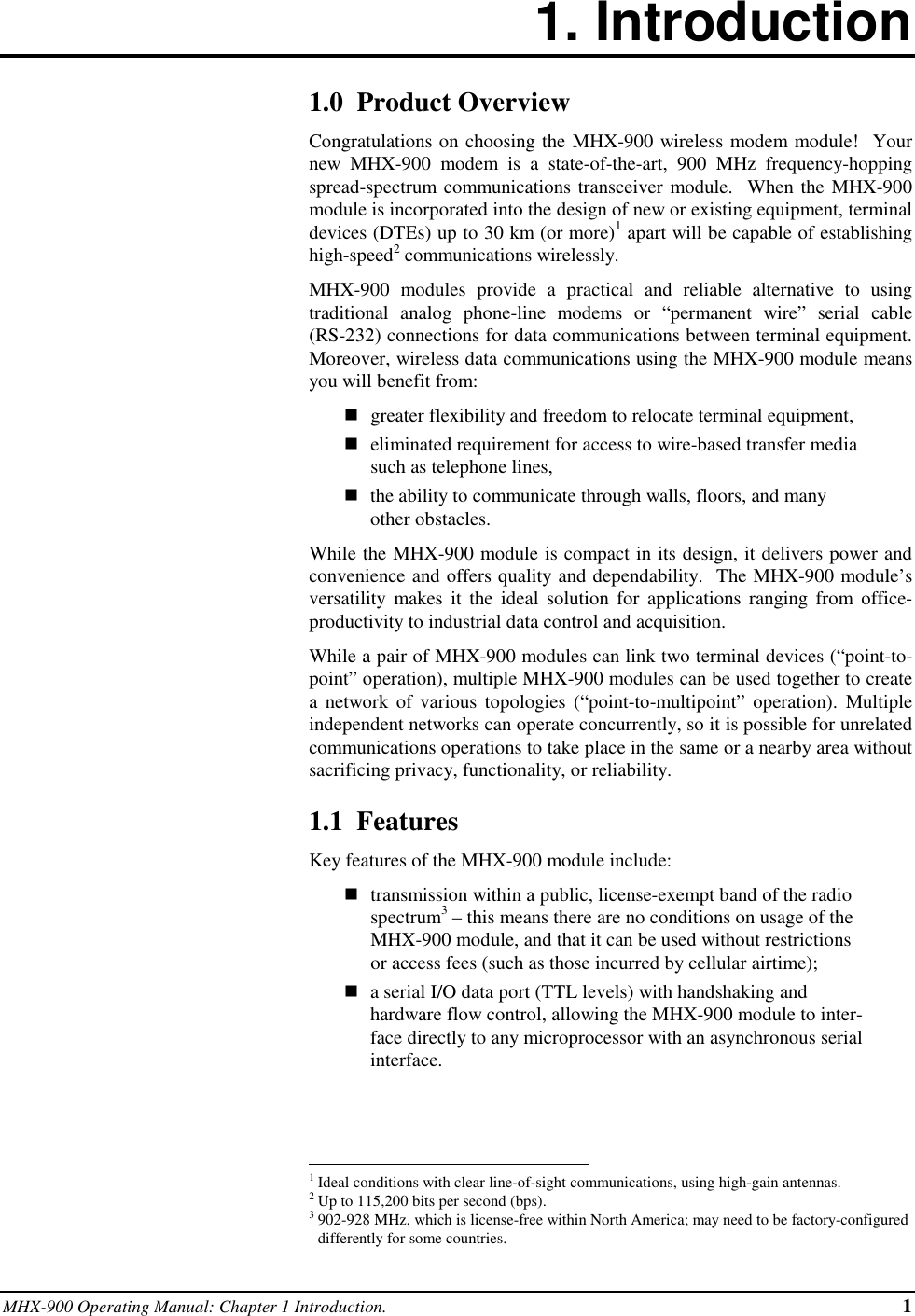
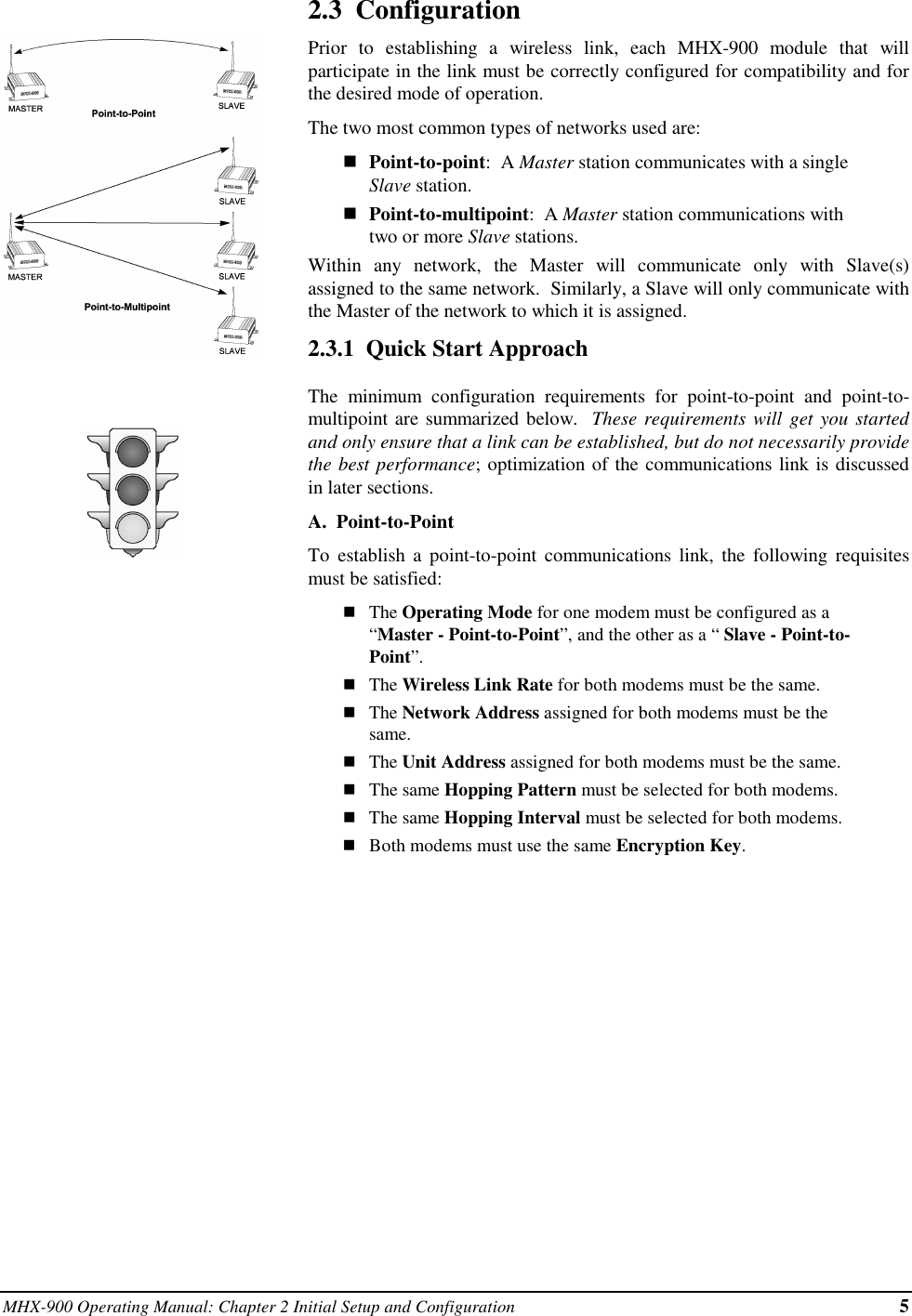
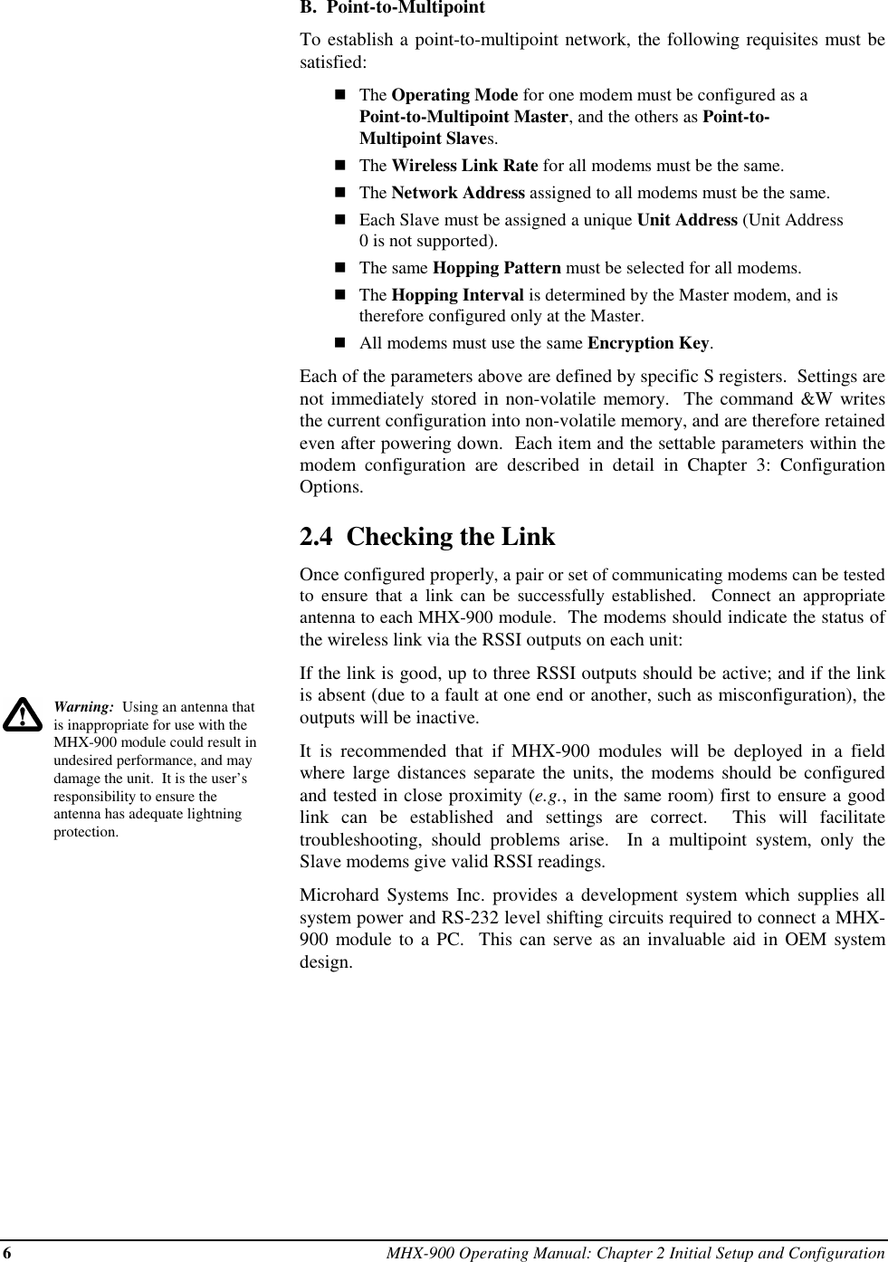
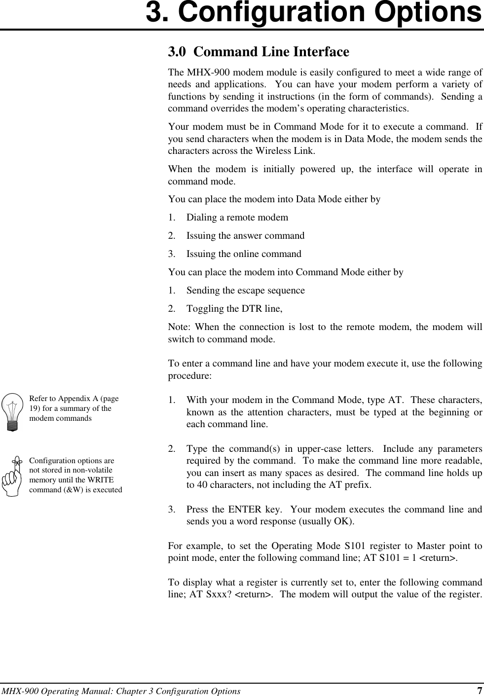
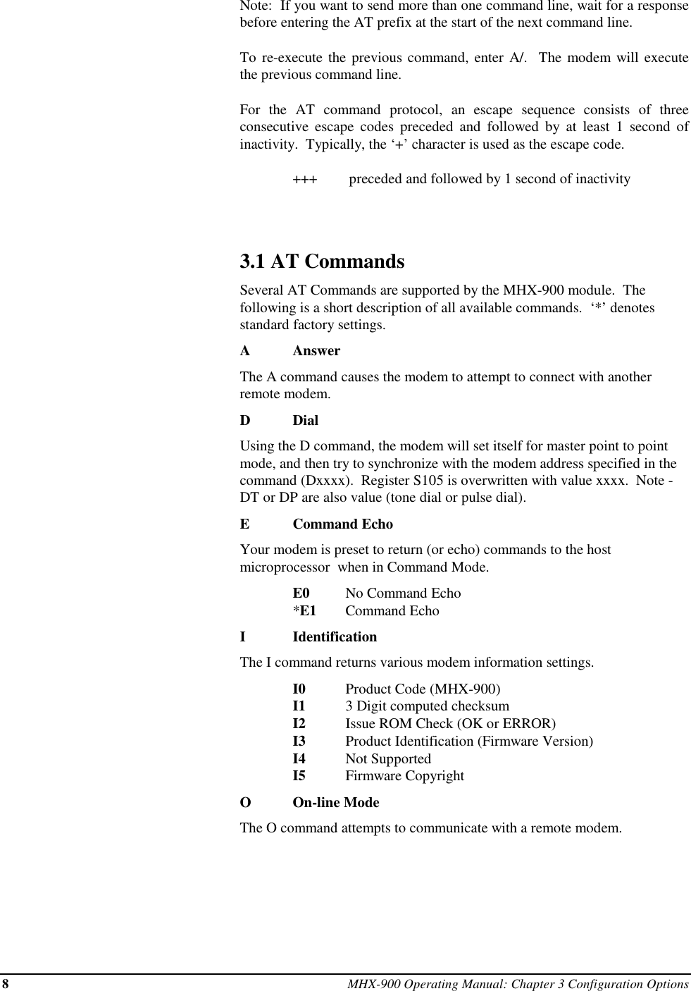
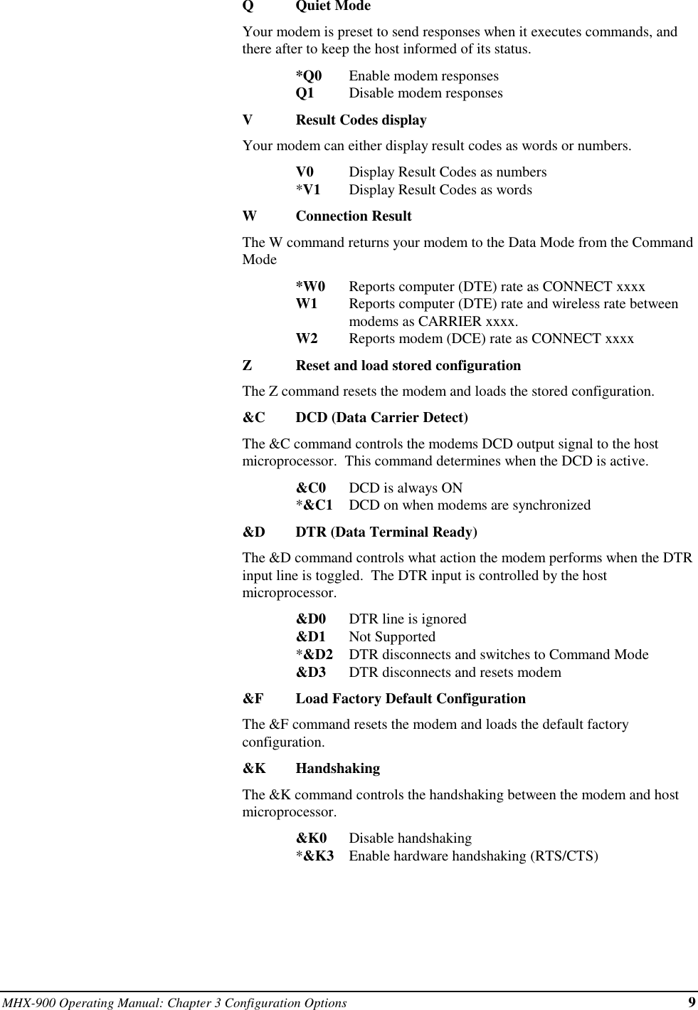
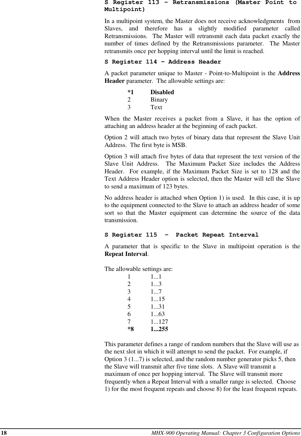
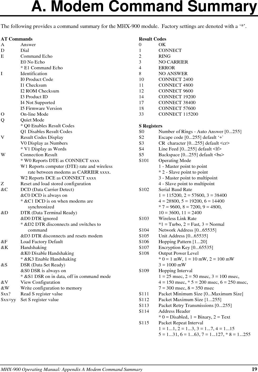
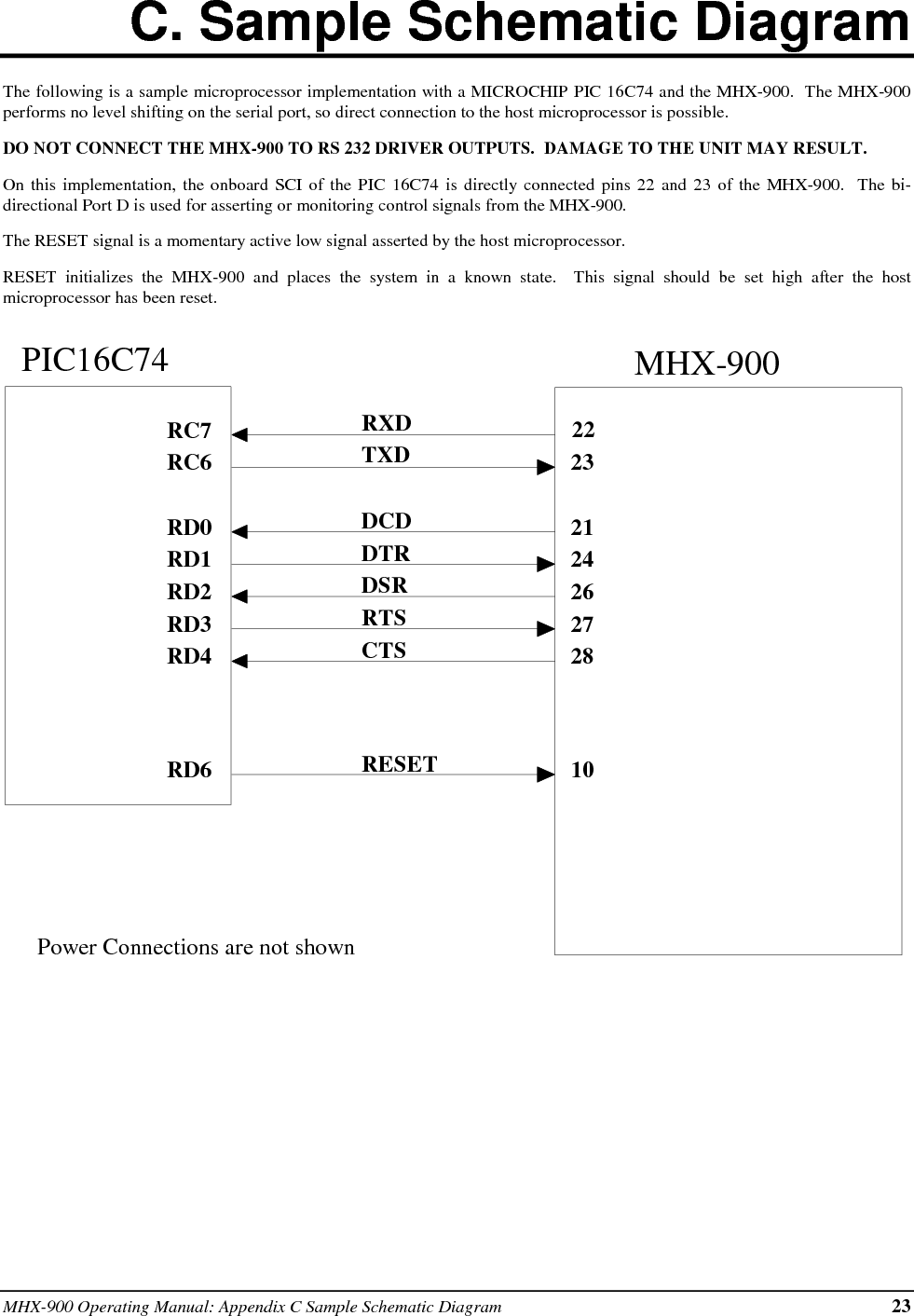
![MHX-900 Operating Manual: Appendix A Modem Command Summary 19A. Modem Command SummaryThe following provides a command summary for the MHX-900 module. Factory settings are denoted with a ‘*’.AT CommandsAAnswerDDialECommand EchoE0 No Echo* E1 Command EchoIIdentificationI0 Product CodeI1 ChecksumI2 ROM ChecksumI3 Product IDI4 Not SupportedI5 Firmware VersionOOn-line ModeQQuiet Mode* Q0 Enables Result CodesQ1 Disables Result CodesVResult Codes DisplayV0 Display as Numbers* V1 Display as WordsWConnection Result* W0 Reports DTE as CONNECT xxxxW1 Reports computer (DTE) rate and wirelessrate between modems as CARRIER xxxx.W2 Reports DCE as CONNECT xxxxZReset and load stored configuration&C DCD (Data Carrier Detect)&C0 DCD is always on* &C1 DCD is on when modems aresynchronized&D DTR (Data Terminal Ready)&D0 DTR ignored* &D2 DTR disconnects and switches tocommand&D3 DTR disconnects and resets modem&F Load Factory Default&K Handshaking&K0 Disable Handshaking* &K3 Enable Handshaking&S DSR (Data Set Ready)&S0 DSR is always on* &S1 DSR on in data, off in command mode&V View Configuration&W Write configuration to memorySxx? Read S register valueSxx=yy Set S register valueResult Codes0OK1CONNECT2RING3NO CARRIER4ERROR8NO ANSWER10 CONNECT 240011 CONNECT 480012 CONNECT 960014 CONNECT 1920017 CONNECT 3840018 CONNECT 5760033 CONNECT 115200S RegistersS0 Number of Rings - Auto Answer [0...255]S2 Escape code [0...255] default ‘+’S3 CR character [0...255] default <cr>S4 Line Feed [0...255] default <lf>S5 Backspace [0...255] default <bs>S101 Operating Mode1 - Master point to point* 2 - Slave point to point3 - Master point to multipoint4 - Slave point to multipointS102 Serial Baud Rate1 = 115200, 2 = 57600, 3 = 384004 = 28800, 5 = 19200, 6 = 14400* 7 = 9600, 8 = 7200, 9 = 4800,10 = 3600, 11 = 2400S103 Wireless Link Rate*1 = Turbo, 2 = Fast, 3 = NormalS104 Network Address [0...65535]S105 Unit Address [0...65535]S106 Hopping Pattern [1...20]S107 Encryption Key [0...65535]S108 Output Power Level* 0 = 1 mW, 1 = 10 mW, 2 = 100 mW3 = 1000 mWS109 Hopping Interval1 = 25 msec, 2 = 50 msec, 3 = 100 msec,4 = 150 msec, * 5 = 200 msec, 6 = 250 msec,7 = 300 msec, 8 = 350 msecS111 Packet Minimum Size [0...Maximum Size]S112 Packet Maximum Size [1...255]S113 Packet Retry Transmissions [0...255]S114 Address Header* 0 = Disabled, 1 = Binary, 2 = TextS115 Packet Repeat Interval1 = 1...1, 2 = 1...3, 3 = 1...7, 4 = 1...155 = 1...31, 6 = 1...63, 7 = 1...127, * 8 = 1...255](https://usermanual.wiki/Microhard-Systems/99P2/User-Guide-37335-Page-23.png)