Microhard Systems HP900 OEM 900 MHz Spread Spectrum Wireless Module User Manual Operating Manual
Microhard Systems Inc OEM 900 MHz Spread Spectrum Wireless Module Operating Manual
UserManual.wiki
>
Microhard Systems
>
HP900 User Manual
User Manual
Navigation menu
Upload a User Manual
Namespaces
Wiki Guide
HTML
PDF
Info
Views
User Manual
Discussion / Help
Navigation

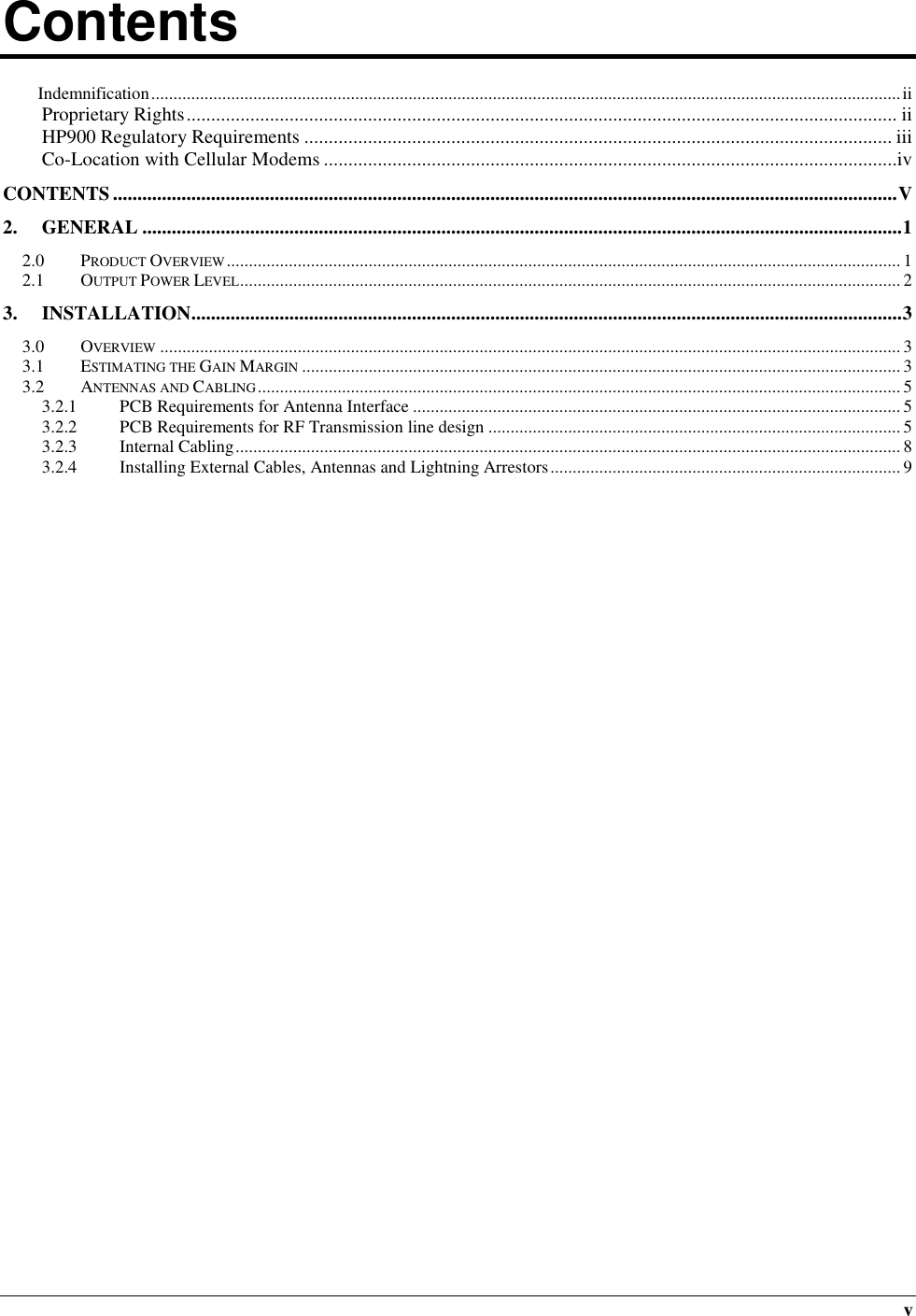
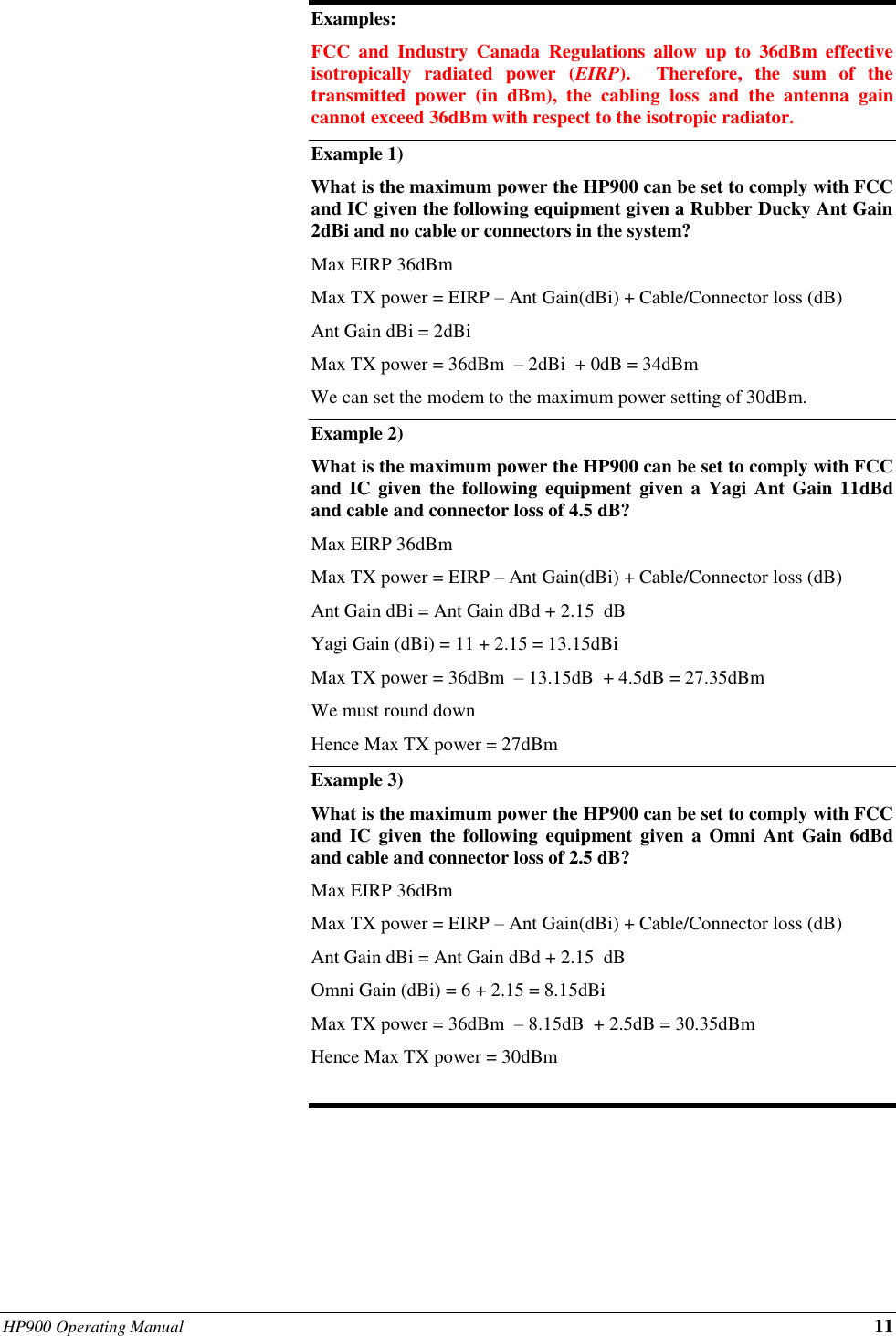
![12 HP900 Operating Manual A. Approved Antennas This radio transmitter [IC: 3143A-HP900] has been approved by Innovation, Science and Economic Development Canada to operate with the antenna types listed below, with the maximum permissible gain indicated. Antenna types not included in this list that have a gain greater than the maximum gain indicated for any type listed are strictly prohibited for use with this device. Group Part Number Description Rubber Ducky MHS031000 3dBi, 900MHz Rubber Ducky Antenna RPTNC Swivel MHS031070 3dBi, 900MHz Rubber Ducky Antenna Reverse SMA Swivel MHS031080 3dBi, 900MHz Rubber Ducky Antenna Reverse SMA Straight Puck Antennas MHS035460 4dBi, Puck Antenna 700-960 MHz/1575-2700 MHz Mag Mount MHS035480 4dBi, Puck Antenna Main and Div 700-960 MHz/1575-2700 MHz Mag Mount MHS035470 4dBi, Puck Antenna Main and Div 700-960 MHz/1575-2700 MHz Permanent Mount Yagi Antennas MHS031311 6dBd, 900MHz Yagi Directional Antenna Antenex, RPTNC Pigtail MHS031431 6.5dBd, 900MHz Yagi Directional Antenna Bluewave, RPTNC Pigtail MHS031501 9dBd, 900MHz Yagi Directional Antenna Antenex, RPTNC Pigtail MHS031441 10dBd, 900 MHz Yagi Directional Antenna Bluewave, RPTNC Pigtail MHS031451 11dBd, 900 MHz Yagi Directional Antenna Bluewave, RPTNC Pigtail Patch Antennas MHS031440 8dBi 900 MHz Patch Antenna, RPTNC Pigtail Omni Directional MHS031251 3dBd, 900MHz Omni Directional Antenna Antenex, RPTNC Pigtail MHS031461 3dBd, 900 MHz Omni Directional Antenna Bluewave, RPTNC Pigtail MHS031321 6dBd, 900MHz Omni Directional Antenna Antenex, RPTNC Pigtail MHS031471 6dBd, 900 MHz Omni Directional Antenna Bluewave, RPTNC Pigtail WARNING: Changes or modifications not expressly approved by Microhard Systems Inc. could void the user’s authority to operate the equipment. This device has been tested with the antennas listed in Appendix A When integrated in OEM products, fixed antennas require installation preventing end-users from replacing them with non-approved antennas. Antennas not listed in the tables must be tested to comply with FCC Section 15.203 (unique antenna connectors) and Section 15.247 (emissions). Please Contact Microhard Systems Inc. if you need more information. Industry Canada: This device has been designed to operate with the antennas listed above, and having a maximum gain of 13.15 dBi. Antennas not included in this list or having a gain greater than 13.15 dBi are strictly prohibited for use with this device. The required antenna impedance is 50 ohms. To reduce potential radio interference to other users, the antenna type and its gain should be so chosen that the equivalent isotropically radiated power (EIRP) is not more than that required for successful communication. This Class B digital apparatus complies with Canadian ICES-003.](https://usermanual.wiki/Microhard-Systems/HP900/User-Guide-4190132-Page-18.png)