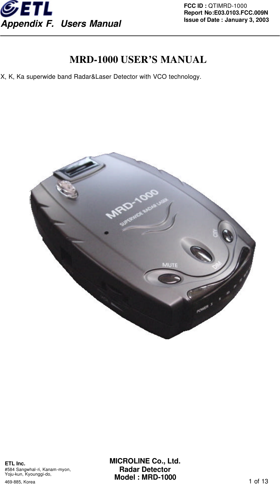
Microline MRD-1000 Radar Detector User Manual users manual

Microline Co., Ltd. Radar Detector users manual

users manual

   Appendix F.  Users Manual ETL Inc.  #584 Sangwhal-ri, Kanam-myon, Yoju-kun, Kyounggi-do,   469-885, Korea                                                                                   1 of 13 FCC ID : QTIMRD-1000 Report No:E03.0103.FCC.009N  Issue of Date : January 3, 2003 MICROLINE Co., Ltd. Radar Detector Model : MRD-1000  MRD-1000 USER’S MANUAL X, K, Ka superwide band Radar&Laser Detector with VCO technology.
   Appendix F.  Users Manual ETL Inc.  #584 Sangwhal-ri, Kanam-myon, Yoju-kun, Kyounggi-do,   469-885, Korea                                                                                   2 of 13 FCC ID : QTIMRD-1000 Report No:E03.0103.FCC.009N  Issue of Date : January 3, 2003 MICROLINE Co., Ltd. Radar Detector Model : MRD-1000 Introduction  Thank you for purchasing MRD-1000 radar&laser detector. The MRD-1000 with VCO technology is a radar&laser detector, which detects not only X, K, and Ka superwide band signals, also laser signals. The MRD-1000 contains visual and audio alerts which warn you of X, K, and Ka superwide band radar signals as well as laser signals in front of you. The MRD-1000 has the technology, which makes it undetectable to the interceptor VG-2 and helps prevent false alarms caused by signals from other radar detectors.  Note: Laws of some area may prohibit the use of a Radar detector. Please check with laws in your area before use of this device. It is your responsibility to abide by laws.
   Appendix F.  Users Manual ETL Inc.  #584 Sangwhal-ri, Kanam-myon, Yoju-kun, Kyounggi-do,   469-885, Korea                                                                                   3 of 13 FCC ID : QTIMRD-1000 Report No:E03.0103.FCC.009N  Issue of Date : January 3, 2003 MICROLINE Co., Ltd. Radar Detector Model : MRD-1000 Table of Contents  1. Profile of Features (1) Power On/Off & Audio Volume Control   (2) City Button (3) Mute Button (4) Dim Button (5) Power Jack (6) Audio Alert Buzzer (7) Laser Optical Sensor   (8) Antenna Opening (9) LED Indicator (8 EA)  2. Description of Features (1) Memory Retention (2) City Button (3) Dim Button (4) Mute Button  3. Interpretation of Alert (1) Radar Alert ( X, K, Ka Band ) (2) Laser Alert (3) VG-2 Guard Alert  4. Installation (1) Connecting the Power (2) Replacing the Fuse (3) Power and Self-test (4) Adjusting Volume  5. Troubleshooting 6. Warranty & Supporting Notes   7. List of Accessories 8. Specifications
   Appendix F.  Users Manual ETL Inc.  #584 Sangwhal-ri, Kanam-myon, Yoju-kun, Kyounggi-do,   469-885, Korea                                                                                   4 of 13 FCC ID : QTIMRD-1000 Report No:E03.0103.FCC.009N  Issue of Date : January 3, 2003 MICROLINE Co., Ltd. Radar Detector Model : MRD-1000 1. Profile of Features 1234DIM56879  (1) Power On/Off & Audio Volume Control Turn the detector on/off and control audio volume level.  (2) City Button   Choose between highway mode and city mode. Press city button to provide reduce false alarms while driving in the city. Press city button again to turn on highway mode, while driving on the highway.    (3) Mute Button Press mute button to provide muting of audio alerts and turning mute LED on. Press mute button again to turn on audio alert mode and mute LED off.  (4) Dim Button  Press the button, MRD-1000 provides 4-levels brightness of LED display with beep sound.  (5) Power Jack Use power cord, MRD-1000 operates with DC12 volt to DC 16volt range.
   Appendix F.  Users Manual ETL Inc.  #584 Sangwhal-ri, Kanam-myon, Yoju-kun, Kyounggi-do,   469-885, Korea                                                                                   5 of 13 FCC ID : QTIMRD-1000 Report No:E03.0103.FCC.009N  Issue of Date : January 3, 2003 MICROLINE Co., Ltd. Radar Detector Model : MRD-1000 (6) Audio Alert Buzzer Provide audio alert with beep.  (7) Laser Optical Sensors Collect laser signals from any direction.  (8) Antenna Opening Radar signals are received by antenna.  (9) LED Indicator (8 EA) 1) POWER : Power On/Off 2) X     : X band Indicator – Signal Strength 1 3) K     : K band Indicator - Signal Strength 1 4) Ka    : Ka band Indicator – Signal Strength 1 5) P1    : X/ K/ Ka/ band Indicator – Signal Strength 2 6) P2    : X/ K/ Ka/ band Indicator – Signal Strength 3 7) MUTE : Mute/Audible Mode Indicator - Mute mode on, Audible mode off 8) CITY  : City/Highway Mode Indicator - City mode on, Highway mode off
   Appendix F.  Users Manual ETL Inc.  #584 Sangwhal-ri, Kanam-myon, Yoju-kun, Kyounggi-do,   469-885, Korea                                                                                   6 of 13 FCC ID : QTIMRD-1000 Report No:E03.0103.FCC.009N  Issue of Date : January 3, 2003 MICROLINE Co., Ltd. Radar Detector Model : MRD-1000 2.  Description of Features (1) Memory Retention Anytime MRD-1000 is turned off or unplugged from the cigarette jack socket, all operating mode you have selected are retained in the memory. When the MRD-1000 turned on again, it is reinstated in MRD-1000’s former mode.  (2) City Button The city mode has been designed to reduce unwanted audio alerts caused by non-traffic radar systems such as intrusion alarms, automatic door openers, microwave traffic signal controllers, and older or poorly-shielded detectors of other vehicles. X band radar signals from non-traffic radar system are frequently encountered in urban and sub-urban areas, MRD-1000 will produce no audio alert only with Band Indicator LED’s blinking at this mode. Since non-police signals are weak, making use of the city mode allows you to drive out of their signal range without audio alert before they reach the already setting signal level. But, police radar signals are generally stronger and will exceed the already setting signal level, they will produce audio alert with Band Indicator LED’s blinking. To select the city mode, press City Button with beep until the city mode Indicator LED turns on. In contrast, to select the highway mode, press City Button with beep until the city mode Indicator LED turns off.    (3) Dim Button Dim Button provides 4-levels selections of brightness. Each time Dim Button is pressed with beep, the Indicator LED will cycle through 4-levels brightness. Use of the Dim Button has no effect on audio alerts.  (4) Mute Button To silence the MRD-1000, press mute button with beep provides muting of audio alerts and turn mute LED on. Pressing mute button again, MRD-1000 turns audio alert mode on and mute LED off.
   Appendix F.  Users Manual ETL Inc.  #584 Sangwhal-ri, Kanam-myon, Yoju-kun, Kyounggi-do,   469-885, Korea                                                                                   7 of 13 FCC ID : QTIMRD-1000 Report No:E03.0103.FCC.009N  Issue of Date : January 3, 2003 MICROLINE Co., Ltd. Radar Detector Model : MRD-1000 3. Interpretation of Alert    Description of LED ( Reference: Profile of Feature No (9) )    (1) Radar Alert (X, K, Ka Band) When MRD-1000 receives radar signal, the following will be occurred: 1) Different audio alerts will be provided for X, K, and Ka band radar signals. The beep sounds will be faster and faster as the radar signal gets stronger. 2) The different Band Indicator LED will turn on or blink in unison with the            different audio alert. 3) The Signal Strength LEDs will blink as the strength of signals.  Ex) Visual Alert (at X Band)     Strength 1: POWER is on, and X is blinking Strength 2: POWER and X are on, and P1 is blinking     Strength 3: POWER and X are on, then P1 and P2 can be automatically blinked  (2) Laser Alert When MRD-1000 receives laser signal, all of Band Indicator LEDs are blinking with siren wailing during 4 seconds.        (3) VG-2 Guard Alert     MRD-1000 provides VG-2 GUARD ALERT making it undetectable to the Interceptor VG-2. When MRD-1000 receive VG-2 signal, all of Indicator LEDs are blinking twice with siren wailing and are turned on. After leaving VG-2 signal area, MRD-1000 automatically returns to normal after 10 seconds. To return to normal intentionally, you have to press Mute Button.
   Appendix F.  Users Manual ETL Inc.  #584 Sangwhal-ri, Kanam-myon, Yoju-kun, Kyounggi-do,   469-885, Korea                                                                                   8 of 13 FCC ID : QTIMRD-1000 Report No:E03.0103.FCC.009N  Issue of Date : January 3, 2003 MICROLINE Co., Ltd. Radar Detector Model : MRD-1000 4. Installation You can attach MRD-1000 to the center of the front window in your car as the following picture.   ( 1 )   ( 2 )   FrontWindshieldglass ( 3 )
   Appendix F.  Users Manual ETL Inc.  #584 Sangwhal-ri, Kanam-myon, Yoju-kun, Kyounggi-do,   469-885, Korea                                                                                   9 of 13 FCC ID : QTIMRD-1000 Report No:E03.0103.FCC.009N  Issue of Date : January 3, 2003 MICROLINE Co., Ltd. Radar Detector Model : MRD-1000 (1) Connecting the Power MRD-1000 is designed to operate on most DC12V negative ground vehicle electrical systems. The power cord provided with the detector has a cigarette lighter socket plug at one end and a DC power jack at the other.      1) Insert the small connector into the DC power jack on the side of the detector. 2) Insert the other end into the cigarette lighter socket of your vehicle.  ◉ If the detector does not operate when you turn it on, remove the adaptor from the cigarette lighter socket and carefully check the socket. Also, check the fuse in the adaptor and your vehicle’s fuse box.  (2) Replacing the Fuse If the detector stops operating, the fuse in the cigarette lighter plug might be blown. Follow these steps to replace it with 250V and 3A fuse. 1)To replace the fuse, unscrew the top of the plug.      cigarette  lightersocket  plugMRD-1000DC power jack
   Appendix F.  Users Manual ETL Inc.  #584 Sangwhal-ri, Kanam-myon, Yoju-kun, Kyounggi-do,   469-885, Korea                                                                                   10 of 13 FCC ID : QTIMRD-1000 Report No:E03.0103.FCC.009N  Issue of Date : January 3, 2003 MICROLINE Co., Ltd. Radar Detector Model : MRD-1000 2)Remove the fuse and check the fuse  to see if it has blown. If it has blown, Replace it.    (3) Power and Self-test To turn the detector on, connect power and turn the On/Off volume control away from you until it clicks.  Volume Off  When powered up, the detector sounds a distinctive tone for each signal and flashes all LEDs in sequence as a self-test. Then all LEDs turn off except the power LED.  (4) Adjusting Volume To change the detector’s volume, turn volume control either away or toward you. 5. Troubleshooting ?? Solutions for Common Problems If the detector does not turn on: ◉ The cigarette lighter socket might be dirty. Clean it with fine emery cloth to ensure a good. Clean connection. ◉ Check the power cord. Be sure all power connectors are properly installed. ◉ Check the fuse that controls power to the cigarette lighter socket.    See your vehicles owner’s manual. ◉ Vehicle electrical problem exists. ◉ Make sure that the volume control is in the ON position.
   Appendix F.  Users Manual ETL Inc.  #584 Sangwhal-ri, Kanam-myon, Yoju-kun, Kyounggi-do,   469-885, Korea                                                                                   11 of 13 FCC ID : QTIMRD-1000 Report No:E03.0103.FCC.009N  Issue of Date : January 3, 2003 MICROLINE Co., Ltd. Radar Detector Model : MRD-1000 ※ Caution : Do not place any metal object other than the cigarette lighter or a cigarette lighter plug in the cigarette lighter socket.  If the detector gives a false alert when the vehicle hits bumps: ◉ Check the vehicle’s electrical system, including main battery cable and alternator connections.  If the receiving signal is weak: ◉ Check the angle of detector. Point to the horizon. ◉ Radar detector antenna and laser sensor is obstructed. Relocate the detector clear of any obstruction outside the windshield, such as a wiper blade. ◉ Relocate the detector clear of window. ◉ Determine whether your vehicle has an electric clear or it is covered with a metallic sun screen.   6. Warranty & Supporting Notes         This warranty shall be effective for one year since the date of retail purchase, does not apply if your MRD-1000 has been subject to modification, improper installation, physical abuse, or if the serial number has been removed.          If you have any problem with MRD-1000, contact us for assistance.              E-mail: sales@e-microline.com                TEL: +82-2-3422-0490              FAX: +82-2-3422-0495   7. List of Accessories (1) Coiled Power Cord (2) Mounting Bracket (3) User’s Manual (4) Suction Cups: 3EA (5) Power Cord Fuse
   Appendix F.  Users Manual ETL Inc.  #584 Sangwhal-ri, Kanam-myon, Yoju-kun, Kyounggi-do,   469-885, Korea                                                                                   12 of 13 FCC ID : QTIMRD-1000 Report No:E03.0103.FCC.009N  Issue of Date : January 3, 2003 MICROLINE Co., Ltd. Radar Detector Model : MRD-1000     8. Specifications ?? Frequency of operation   ?? X Band: 10.525GHz±25MHz ?? K Band: 24.150GHz±100MHz ?? Ka Band: 34.7GHz±1300MHz ?? Laser Spectral Response: 800~1,100nm ?? General Specification ?? Operating Temperature: -4 to 176℉ (-20 to 80℃) ?? Power Condition: 12~16V DC, 260mA ?? Dimension(HWL): 1.3×2.8×4 inches (33×71×103 mm) ?? Weight: 4.23 oz. (120g)
   Appendix F.  Users Manual ETL Inc.  #584 Sangwhal-ri, Kanam-myon, Yoju-kun, Kyounggi-do,   469-885, Korea                                                                                   13 of 13 FCC ID : QTIMRD-1000 Report No:E03.0103.FCC.009N  Issue of Date : January 3, 2003 MICROLINE Co., Ltd. Radar Detector Model : MRD-1000 FCC Information FCC Part 15.105  Note: This equipment has been tested and found to comply with the limits for a Class B digital device, pursuant to part 15 of the FCC Rules.   These limits are designed to provide reasonable protection against harmful interference in a residential Installation. This equipment generates, uses, and can radiate radio frequency energy and, if not installed and used in accordance with the instructions. May cause harmful interference to radio communications. However, there is no guarantee that interference will not occur in a particular installation. If this equipment does cause harmful interference to radio or television reception, which can be determined by turning the equipment off and on, the user is encouraged to try to correct the interference by one or more of the following measures:    - Reorient or relocate the receiving antenna. - Increase the separation between the equipment and receiver. - Connect the equipment into an outlet on a circuit different from that to which the     receiver is connected - Consult the dealer or an experience radio / TV technician for help  FCC Part 15.21  Changes or modifications not expressly approved by the party responsible for compliance Could void the user`s authority to operate the equipment

Navigation menu