Microlise MTU4 Vehicle tracking and telematics unit User Manual Microlise MTU4 Technical Manual V1 11
Microlise Limited Vehicle tracking and telematics unit Microlise MTU4 Technical Manual V1 11
Contents
- 1. Exhibit 08 Users Manual
- 2. Exhibit 08 Users manual
Exhibit 08 Users manual

MTU4
MTU4 Technical Manual
Issue 1.11
10 Oct 2012

MTU4
Page 2 of 14 Issue 1.11 MTU4 Technical Manual
Conditions
This publication and all associated programs and other documents are Copyright (C) 2012 by Microlise. No
part of this publication, or its associated programs and other documentation, may be reproduced,
transmitted, transcribed, stored in a retrieval system, or transcribed into any human or computer language, in
any form or by any means, electronic, mechanical, magnetic, optical, chemical, manual or otherwise, without
the express written permission of Microlise.
The issue and/or possession of this document does not entitle the recipient to have or to use, or have access
to, the
Microlise Tracking Unit 4 (MTU4)
product. Such use or access is subject to separate
contracts or product licences. Whilst every effort is made to ensure that the information contained in this
document is correct, Microlise makes no representations or warranties with respect to the contents hereof
and does not accept liability for any errors or omissions. If for any reason the foregoing disclaimer is
ineffective, the liability of Microlise shall not exceed that which it may have under the contract pursuant to
which this document has been supplied.
Any particular release of the
MTU4
product may not contain all the facilities described in this document.
New releases of the product may contain extra facilities which are not described in this document. Microlise
will, in this latter case and if requested, supply additional information about any extra facilities supplied with a
user's particular release of the product.
Battery pack safety
The MTU4 contains a Li-ion battery pack. This is not user replaceable. If replacement is needed please
contact Microlise Service.
CAUTION: RISK OF EXPLOSION IF BATTERY IS REPLACED BY AN INCORRECT TYPE. DISPOSE OF
BATTERY ACCORDING TO THE INSTRUCTIONS.
Please note: Batteries must not be disposed of with normal household or business waste. Please dispose of
inaccordance with local regulations in force for battery disposal.
FCC Rules
This device complies with part 15 of the FCC Rules. Operation is subject to the following two conditions: (1)
This device may not cause harmful interference, and (2) this device must accept any interference received,
including interference that may cause undesired operation.
Changes or modifications to the MTU4 unit not expressly approved by Microlise could void the user's
authority to operate the equipment.
Note: This equipment has been tested and found to comply with the limits for a Class B digital device, pursuant to part 15 of the FCC
Rules. These limits are designed to provide reasonable protection against harmful interference in a residential installation. This
equipment generates, uses and can radiate radio frequency energy and, if not installed and used in accordance with the instructions,
may cause harmful interference to radio communications. However, there is no guarantee that interference will not occur in a particular
installation. If this equipment does cause harmful interference to radio or television reception, which can be determined by turning the
equipment off and on, the user is encouraged to try to correct the interference by one or more of the following measures:
• Reorient or relocate the receiving antenna.
• ncrease the separation between the equipment and receiver.
• Connect the equipment into an outlet on a circuit different from that to which the receiver is connected.
•
Consult the dealer or an experienced radio/TV technician for help.
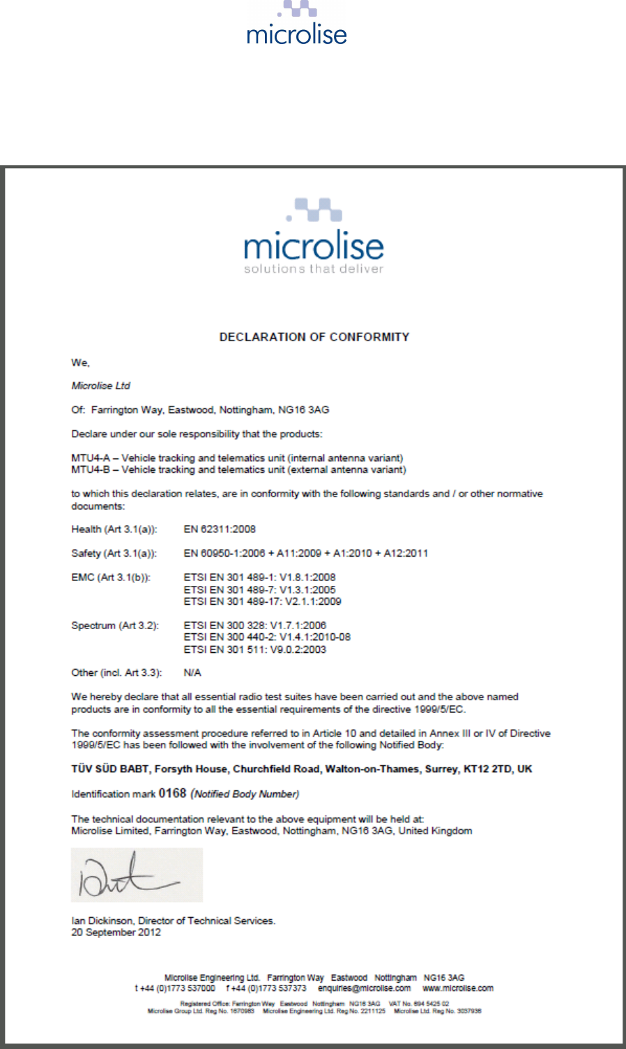
R&TTE directive
0168
This device complies with the European Radio and Telecommunication Terminal
Equipment (R&TTE) directive, including product safety and electrical interference
directives.
MTU4
Page 3 of 14 Issue 1.11 MTU4 Technical Manual
Revision history
Issue 1.0 Initial draft for internal review. 23 January 2012
Issue 1.1 First release. 25 January 2012
Issue 1.2 Battery capacity incorrectly stated as 5.7 Ahr. Corrected to 5.2
AHr. 30 January 2012
Issue 1.3 1. GSM / Blutooth audio call set up details added.
2. Bluegiga BlueTest3 test application details added.
3. External antenna guidance notes added.
20 February 2012
Issue 1.4 1. Battery warning and disposal information added.
2. In-line wiring harness fuse type specified.
27 March 2012
Issue 1.5 Upper supply voltage limit revised to 32V d.c. 14 June 2012
Issue 1.6 1. Signal path annotation added to block diagram
2. FCC regulatory information added
2 Aug 2012
Issue 1.7 1. FCC Class B “information to the user” added
2. Description of operation updated to include details of all
sections of the circuit and both antenna options.
7 Aug 2012
Issue 1.8 Details of GSM and Bluetooth antennas added 13 Aug 2012
Issue 1.9 Details of diagnostic screen added 16 Aug 2012
Issue 1.10 Copy of European Declaration of Conformity added, R&TTE / CE
compliance detail and details of functions not supported in USA 30 Sept 2012
Issue 1.11 External antenna specifications for FCC compliance added 10 Oct 2012

MTU4
Page 4 of 14 Issue 1.11 MTU4 Technical Manual
Contents
1
Overview ................................................................................................................................................... 5
2
Installation ................................................................................................................................................. 5
3
Wiring ........................................................................................................................................................ 6
4
Description of operation ............................................................................................................................ 6
5
Antenna details ......................................................................................................................................... 7
5.1
Bluetooth ............................................................................................................................................ 7
5.2
GSM ................................................................................................................................................... 7
6
Tuning and serviceable parts .................................................................................................................... 7
7
Block diagram ........................................................................................................................................... 8
8
Configuration and diagnostics menu ........................................................................................................ 8
8.1
Establishing a GPRS connection and monitoring the GPS stream ................................................. 10
8.2
Establishing a voice call, using a Bluetooth headset ....................................................................... 10
8.3
Using the Bluegiga BlueTest3 application ....................................................................................... 11
9
Technical specification ............................................................................................................................ 13
10
EU Declaration of Conformity ................................................................................................................. 14
MTU4
Page 5 of 14 Issue 1.11 MTU4 Technical Manual
1 Overview
The
Microlise Tracking Unit 4 (MTU4)
is battery backed, vehicle tracking and telematics unit
utilizing GPS, GSM / GPRS and Bluetooth technology.
The unit is available in two hardware variants:
a) MTU4-A with integral GSM and GPS antennas
b) MTU4-B with SMA connectors for connecting external GSM and GPS antennas
Units are supplied to customers pre-configured by Microlise with appropriate configurations along with
wiring harnesses to suit the intended application.
2 Installation
The MTU4 is designed for installation both within the vehicle cab and also for installation on a trailer.
Depending on the application the device may be permanently powered (e.g. an in cab installation) or
powered only periodically (e.g. in a trailer tracking application only when the trailer is hooked up to a
tractor unit.) However, in either application the unit is designed to make efficient use of the power
available through the use of sleep modes when there is no activity.
When selecting a suitable mounting location, please be aware of:
• Excessive temperatures (operating temperature: -25°C to 55°C)
• Corrosive fluids
• Areas where the unit may obstruct the drivers view or impede operation of the vehicle
• Locations which may shield the unit and affect GPS and GPRS reception.
If an external antenna is being used with the unit, then it should be located at least 30 cm from the
MTU4 and any other ECU in the vehicle. Any excess antenna cable must not be tightly coiled up.
The installation must be carried out in accordance with FCS1362:2010 or later, by a competent auto-
electrician.
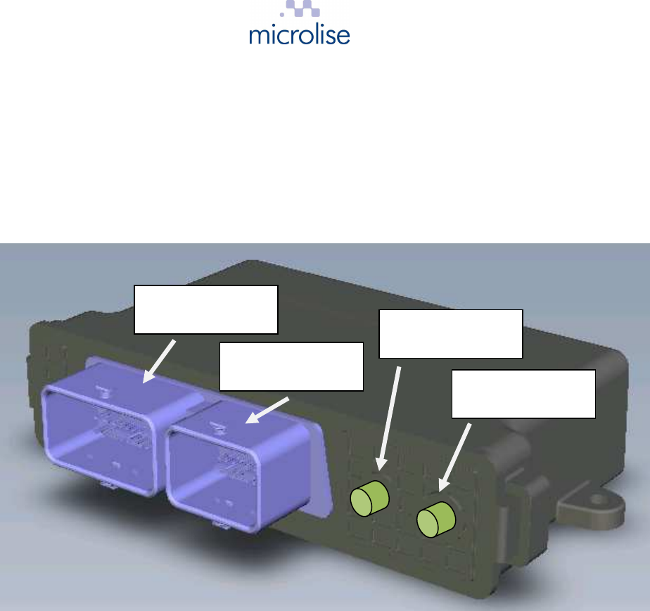
GPS connection
(MTU4-B only)
GSM connection
(MTU4-B only)
Primary 48 way
connection
Secondary 32 way
connection

MTU4
Page 6 of 14 Issue 1.11 MTU4 Technical Manual
3 Wiring
For basic in cab installations only the following wires need be connected:
MTU4 primary
connector pin no Wire colour Signal In-line fuse*
required
P2M Red 12V or 24V supply 3A
P3K Yellow Ignition 1A
P4K Orange Engine run 1A
P1M Black Ground None
For bench testing, connect the red, yellow and orange wires to a +12V or 24V supply and the black
wire to 0V / Ground.
* Fuses and all replacements need to be automotive blade type ATO.
4 Description of operation
Providing external power is applied, or the internal battery is sufficiently charged, and the unit is within
GPS and GPRS coverage the unit will periodically (based on time and/or distance, and configuration)
transmit location and telematics information to the relevant Microlise system.
If out of GPRS coverage then messages are stored into non-volatile Flash memory for transmission
later when a GPRS connection can be established.
Whilst operating on external power the unit will charge the internal battery as required.
Two CAN interfaces are incorporated which are typically used to either listen for, or request
information on automotive CAN busses.
The unit incorporates three RS232 interfaces which can be used for connection of a variety of
peripherals, e.g. Mobile Data Terminals, refrigeration temperature monitoring equipment, printers,
sensors or other devices.
A Dallas 1 wire interface is provided. This is typically used for driver identification via Dallas iButtons,
but could also be used with any other device in the “1 wire” range.
Connection can be made to a vehicle Digital Tachograph via the built in digital tachograph interface.
This can be as an alternative way to identify the driver and also capture information needed to comply
with regulations regarding drivers’ hours.
The unit incorporates seven digital inputs. Two are available for monitoring ignition status, another for
engine run, the remainder are general purpose inputs which can be used for monitoring doors
switches, panic buttons or other digital signals.
A real time clock is incorporated for time-stamping all events recorded by the unit.
The unit monitors its own internal temperature. Battery charging is only permitted when the
temperature is within the specified limits of the battery pack.
The Bluetooth interface can be used for diagnostics, for connection to peripheral devices, e.g. a data
terminal, and also for audio connection to a Bluetooth car kit for hands free voice calls.
A USB OTG (on the go) port is provided. This can also be used for diagnostics, but can also be used
for connection to a range of USB host or slave devices.
Using the built in Codec and a audio output via Bluetooth the unit can play tones or make audible
announcements to the driver of a vehicle, e.g. to provide real time feedback on driving style.
Depending on the device purchased, the unit is fitted with internal GSM and GPS antennas, or is
provided with SMA connections to which separate, or a combined GSM/GPS, antennas may be
connected.
A microSD card may be fitted internal for applications requiring additional Flash storage capacity.

MTU4
Page 7 of 14 Issue 1.11 MTU4 Technical Manual
Two relay outputs with change over contacts are provided for remote control of other devices.
The built in accelerometer can be used to monitor harsh braking, acceleration, cornering, and any lean
of the vehicle.
The built in GSM modem supports four GSM frequency bands (850, 900, 1800 & 1900 MHz). The 900
and 1800 MHz bands are used in Europe, but are not operational in the USA. The 850 and 1900 MHz
bands are the only bands used for GSM in the USA and Canada.
5 Antenna details
5.1 Bluetooth
Both variants of the product (MTU4-A and MTU4-B) incorporate the Bluegiga WT32-A Bluetooth
module. This module has a built in chip antenna with a peak gain of 1.5 dBi.
5.2 GSM
The MTU4-A has a build in custom designed GSM antenna. This has a gain of 0 dBi.
The MTU4-B has a SMA connection to which an external GSM antenna can be connected. A typical
antenna is the Hirshmann GPS1890LP, the GSM gain of which is 0 dBi.
Please note: To comply with FCC regulations the external antenna gain, including cable loss, must
not exceed 3.0dBi at 1900 MHz / 1.4dBi at 850 MHz
6 Tuning and serviceable parts
The MTU4 contains no user tunable parts. The MTU4 contains no user serviceable parts.
MTU4
Page 8 of 14 Issue 1.11 MTU4 Technical Manual
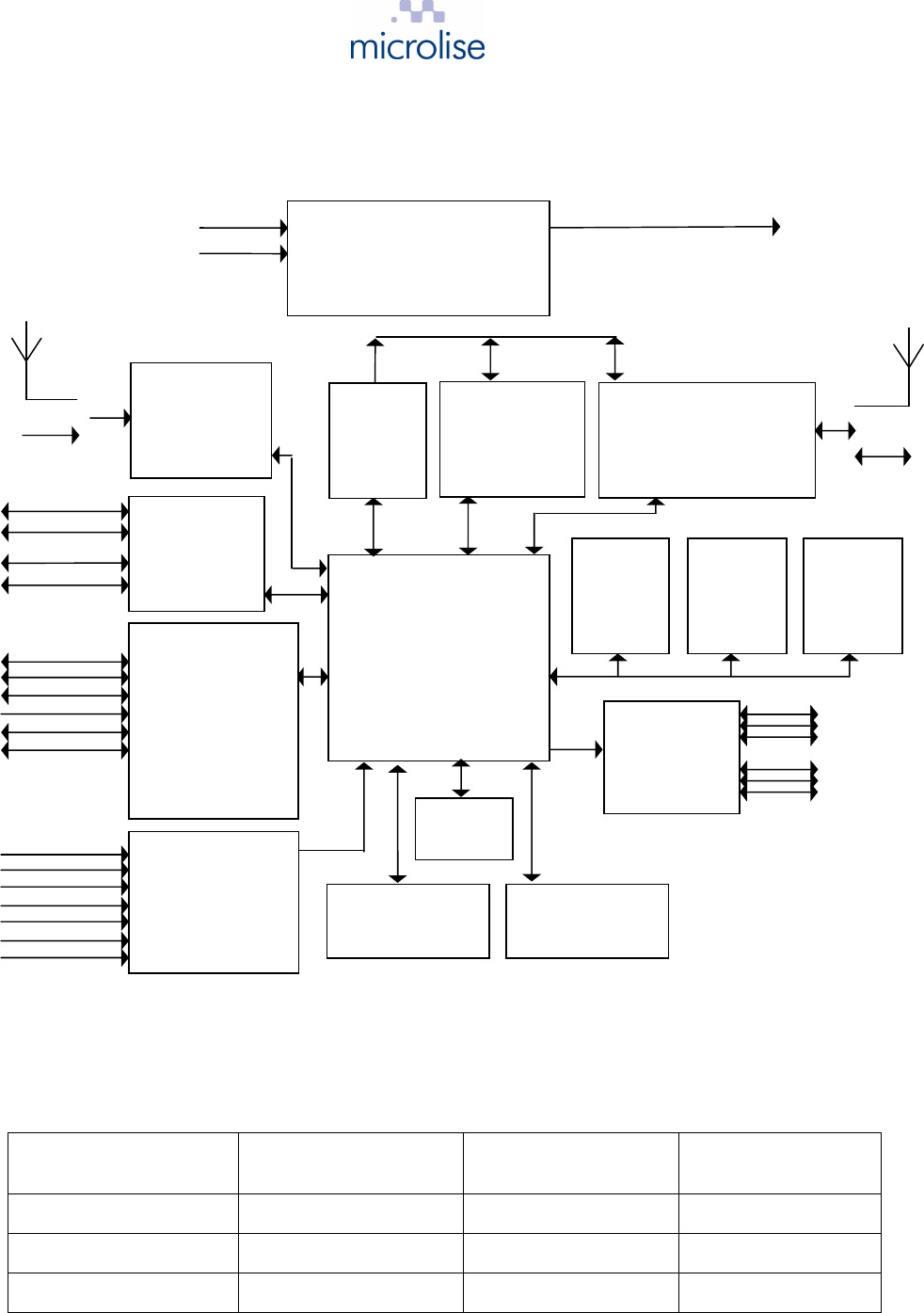
7 Block diagram
8 Configuration and diagnostics menu
To access the configuration and diagnostics menu a PC or laptop with a RS232 port (or a USB to
RS232 adaptor) should be connected to the MTU4 as follows:
MTU4 primary
connector pin no MTU4 signal PC / laptop serial port
pin no PC serial port signal
P3C DTE-RX 3 Transmit
P1C DTE-TX 2 Receive
P1B Ground 5 Ground
On the PC or laptop execute a terminal program, e.g. Hyperterminal, and set the RS232 configuration
as follows: 115200 baud, 8 bit, no parity, 1 stop bit
By default the unit will output debug messages to the terminal program.
RF
Ignition
Iso Ignition
Engine run
Input 0
Input 1
Input 2
Input 3
Digital
o/ps
I2C I2C
RS232 Serial 0
RS232 Serial 1
RS232 Serial 2
Digital tacho
Dallas 1 wire
RS485 Serial
Address &
data bus
CAN
data
Serial data
Serial
data
Serial
data
Serial
data
+VE
GND
PSUs, 3.7V 5.2Ahr Li-ion battery,
charger and power management
STM32F207IG
microprocessor
8MHz xtal
uBlox LEA-6
GPS receiver
1575.42 MHz
12V / 24V d.c.
supply
Telit GE864 QUAD V2
GSM / GPRS modem
850/900/1800/1900 MHz
CAN interface
x 2
Serial interfaces
(RS232 DTE,
RS232 DCE
RS232 TX/RX,
Digital tacho,
Dallas 1 wire
RS485)
1.832MHz xtal
Ignition, isolated
ignition, engine run
and 4 x general
purpose inputs
32MB
Flash
memory
4MB
SRAM
memory
Relay
outputs x 2
3 axis
accelerometer
uSD
memory
card slot
Codec
12.288
MHz xtal
Bluegiga WT32
Bluetooth
(integral 2.4GHz
antenna)
Real time clock
32.769kHz xtal
Temp
sensor
5V, 4V5, Vbatt & 3V0 rails
Audio
Serial data
I2C
Digital
i/ps
CAN0 H
CAN0 L
CAN1 H
CAN1 L
Relay 0 (NO,
NC & COM)
Relay 1 (NO,
NC & COM)
RF
Internal GSM
antenna
(MTU4-A)
Link cable to
external SMA
(MTU4-B)
Internal GPS
antenna
(MTU4-A)
Link cable to
external SMA (MTU4-B)

MTU4
Page 9 of 14 Issue 1.11 MTU4 Technical Manual
On hitting the “Esc” key the following menu will appear:
Main Menu
1 - Debugs
2 - Logs
3 - View Config
4 - Test
5 - Configure
6 - Download
7 - CAN Event Data
8 - CAN Log Data
9 - Advanced Menu
Enter option >
Press ‘4’ to select the “Test” screen as follows:
Status Screen
MTU4 Time :Thursday, 16/08/12,20:43:37
IMEI :351934045707440 Telit 865: 10.00.023
Ver :1.5.6 crc 0x2c40 size:384464
IMSI :234159119456948
ICCID :89441000302007987555
Sig Q :13 = 41 Percent
GPRS :Connected
IP :10.180.30.211
SRVR :94.125.17.212 Connected 5432
Power Retain :7200 Sleep: 900=0 Re-try: 6
VIN :00000000000000000 source 0x00
GPSVer :HW:00040007 SW:7.03 (45969)
Latitude : 52.91347120 Power :Off (0.32v)
Longitude : -1.23514640 Ignition :Off
GPSFix :TRUE Ch0 (DPU) :Low
Num Sats :5 Ch1 (DPU) :Low
Speed : 0.000000 Ch2 (DPU) :Low
Course : 0.000000 Ch3 (DPU) :Low
Distance :0000014934 Shut Down :16s
GPS Antenna :0 Batt Capacity :unknown (3.65v)
GPS err (fHacc) : 39.00 Charge State :Standby
GPS FixCount : 0
MainMin :2498 MainMax :3873 MainCurrent :2498 MainMaxT :0022
TIM5 Counters (10us/cnt)
Loop Time : Max :00002181 Current :00000039 (00000494)
Func 03 : Max :00002142 Current :00000014 (00002142)

MTU4
Page 10 of 14 Issue 1.11 MTU4 Technical Manual
For advanced options, press ‘9’. The following menu will then appear:
Advanced Menu
a - Direct GSM
b - Direct GPS
c - Direct Bluetooth
d - Device Tests
e - Device Info
f - Current Settings
g - Upload
h - Erase Config
i - Erase Reports
j - Erase Datastore
k - Erase Debugs
l - Immediate Reset
m - Erase ASSET / set VIN
n - Power Supply Control
y – Direct BlueTest3
z - Prod Test
Enter option >
To return to the “Main Menu” press “Esc”..
8.1 Establishing a GPRS connection and monitoring the GPS stream
Select menu options ‘9 a’ for a “Direct GSM” connection.
Once selected, AT commands may be sent directly to the integral GSM modem.
e.g. type “AT+CGATT=1” (without double quotes) to put the modem into auto attach mode for GPRS
testing.
Press “Ctrl” “g” to switch to the GPS stream and “Ctrl” “a” to switch back to the GSM modem, if
needed.
Once testing is complete press “Esc” to return to the “Advanced Menu” and “Esc” again to return to the
“Main Menu”.
Note: Pressing “Esc” when in any “Direct … “ mode will cause the unit to resume normal tracking
operations and close any GPRS connection or GSM call.
8.2 Establishing a voice call, using a Bluetooth headset
Select menu option ‘9 c” for a “Direct Bluetooth” connection, then follow the steps below:
1. Type “AT” (without quotes) and check for response “OK”
If pairing with the Bluetooth headset has been carried out previously, then skip steps 2 to 12 and jump
to step 13.
2. Type the following commands to clear any previous pairing:
SET BT PAIR *
SET RESET
3. Check for Bluegiga copyright message and “READY”

MTU4
Page 11 of 14 Issue 1.11 MTU4 Technical Manual
4. Type the following commands:
SET BT CLASS 200408
SET PROFILE HFP-AG ON
SET BT AUTH * 0000
5. Set the headset into discoverable mode by holding the silver button pressed for 6 seconds. The
led should then flash red / blue.
6. Type the following command:
PAIR 00:23:7F:7D:AB:8D
(replace “00:23:7F:7D:AB:8D” with the MAC address of headset being used)
7. Check for the response:
PAIR 00:23:7F:7D:AB:8D OK
8. Type the following command:
CALL 00:23:7F:7D:AB:8D 111E HFP-AG
9. Check for response “CONNECT 0 …. “
10. Pressing volume on headset should cause responses to appear in terminal window.
11. Power down the MTU4 and the headset, then re-apply power / switch on both.
12. Select menu option “9 c” for “Direct Bluetooth”
13. Type “RING”, then press the silver button the headset twice
14. Check for the response:
RING 1 00:23:7f:7d:ab:8d SCO
15. Press “Ctrl” “a” to switch to “Direct GSM” mode
16. Type the following commands:
AT#CAP=2
ATD07977008706; (
Change the phone number to suit. Note the trailing “;”)
17. A voice call should now be established.
18. To end the GSM call type “ATH”
19. To end the Bluetooth audio connection press “Ctrl” “b”, then type “HANGUP”
Once testing is complete press “Esc” to return to the “Advanced Menu” and “Esc” again to return to the
“Main Menu”.
Note: Pressing “Esc” when in any “Direct … “ mode will cause the unit to resume normal tracking
operations and close any GPRS connection or GSM call.
8.3 Using the Bluegiga BlueTest3 application
Select menu option ‘9 y” for a “Direct BlueTest3” connection.
The following should appear:
Direct BlueTest3
Exit the terminal program and start the “BlueTest3” utility
In the "Transport" box select "BCSP"
In the "Serial Port" box choose the COM port previously used by the terminal application..
In the "Baud Rate" box choose "115200"

MTU4
Page 12 of 14 Issue 1.11 MTU4 Technical Manual
Click "OK"
Communication should now be established with the BlueGiga module.

MTU4
Page 13 of 14 Issue 1.11 MTU4 Technical Manual
9 Technical specification
Item Specification
Power Supply
6 – 32 V dc or internal 5.2Ahr 3.7V Li-ion battery
Current Consumption
Sleep:
Operating:
< 2mA
< 2A
Supported interfaces: RS232 x 2 (1 x DTE, 1 x DCE)
RS232 TX / RX only
Digital tachograph serial
Dallas 1 wire
Engine run
Ignition
Isolated ignition
Analog / digital inputs x 4
Relay outputs (NO / NC) x 2
CAN bus interface x 2
RS485 interface
USB host / slave OTG port
Bluetooth (HF-AG and SPP)
Accelerometer
3V SIM card interface
GSM/GPRS
Modem:
Power:
GPRS:
Voice support:
SMS support:
Quad band (850, 900, 1800, 1900 MHz bands supported)
850/900 Class 4 (2W)
1800/1900 Class 1 (1W)
Multi-slot Class 10, Class B
MT & MO
MT & MO
GPS
Receiver:
Channels:
Accuracy:
Antenna supply:
High-sensitivity, L1 frequency, C/A code
50 channels, SBAS (WAAS, EGNOS, MSAS support)
2.5m CEP
3V output for active antennas
Mechanical
Dimensions:
Weight:
180mm x 40mm x 115mm
approx. 500g
Environmental
Operating temperature:
Storage temperature:
Ingress protection:
-25°C to +55°C
-40°C to +85°C
IP69k
MTU4
Page 14 of 14 Issue 1.11 MTU4 Technical Manual
10 EU Declaration of Conformity