AutoVISION™ Software Introduction LABS Auto VISION Training
2013-01-15
: Microscan Autovision-Software-Labs- Training AutoVISION-Software-LABS-_Training Q12013 LaunchCentral PartnerSite
Open the PDF directly: View PDF ![]() .
.
Page Count: 28

AutoVISION™ Software Tools
Training Labs
2 | © 2 0 1 3 M i c r o s c a n S y s t e m s , I n c .
Welcome
This lab booklet is used in conjunction with the AutoVISION™ Software training
Tips:
Take notes; write in your lab book!
Learn about each tool before going through each project, to ensure thorough
understanding.
For parts of this lab, you will need a Vision HAWK or Vision MINI camera
connected to your PC
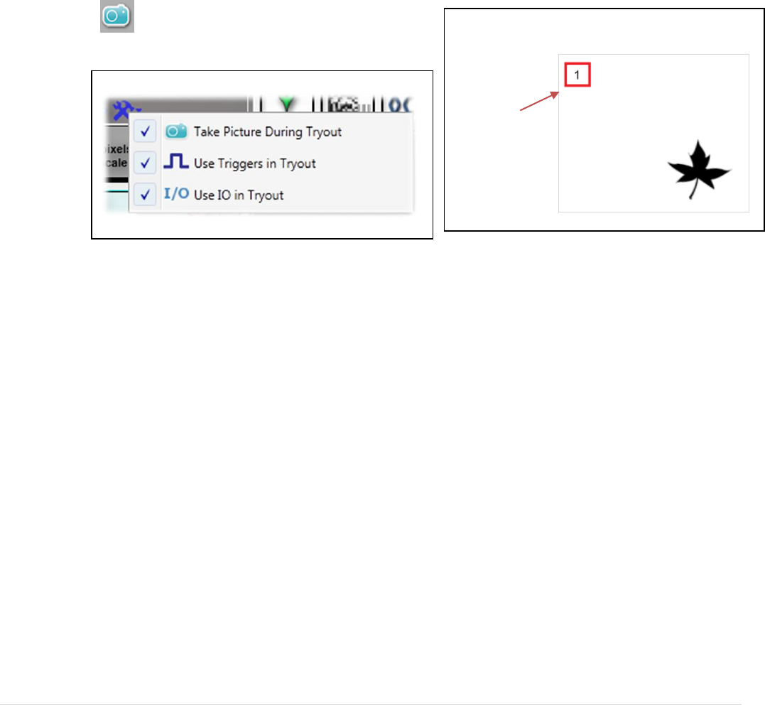
When using stored image files, be sure to build the job on the first image for that
lab. To acquire the first image:
Select the lab folder for the current project.
Under Inspection options, check “Take Picture During Tryout”.
Click the acquire image button in the image area.
Store jobs on disk using “Save As” so you can keep copies of different stages of
your job. This will allow you to revert to earlier steps if you get stuck.
Click the Acquire button until image 1
is displayed.
Enable Take Picture During Tryout
© 2 0 1 3 M i c r o s c a n S y s t e m s , I n c . | 3
Using a live camera
The remainder of the labs requires the use of a live camera to learn about runtime
features. This section of the hands on lab will teach you how to:
1. Set up a live camera and creating a job
2. Load multiple jobs on the camera
3. Switch between jobs at runtime
4. Create a web HMI
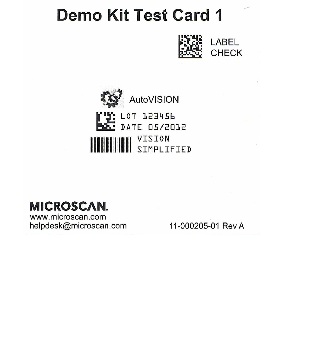
The lab is based on the Demo Kit Test Card1 with part number 11-000205-01:
4 | © 2 0 1 3 M i c r o s c a n S y s t e m s , I n c .
Lab1: reading Data matrix and checking the GS1 syntax
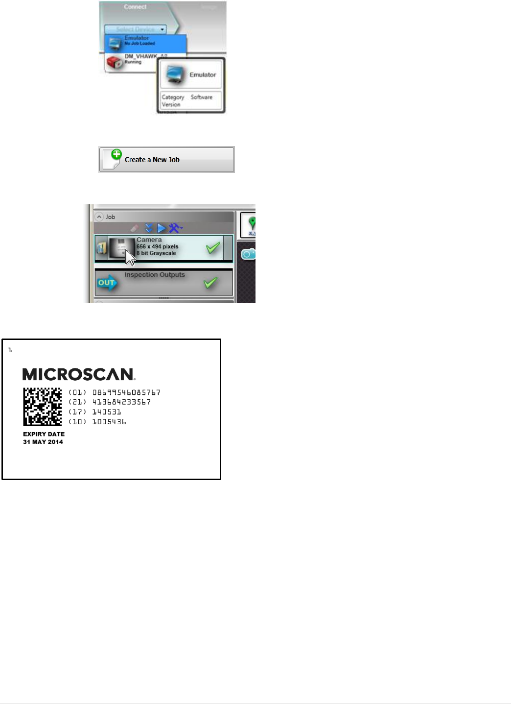
1. Open AutoVISION™ and select the Emulator.
2. Create a new Job.
3. Change the Image directory to the folder containing the Lab1 images.
4. Add a Decode tool to the image area on image 1.
5. Adjust the tool ROI to cover most of the field of view
© 2 0 1 3 M i c r o s c a n S y s t e m s , I n c . | 5
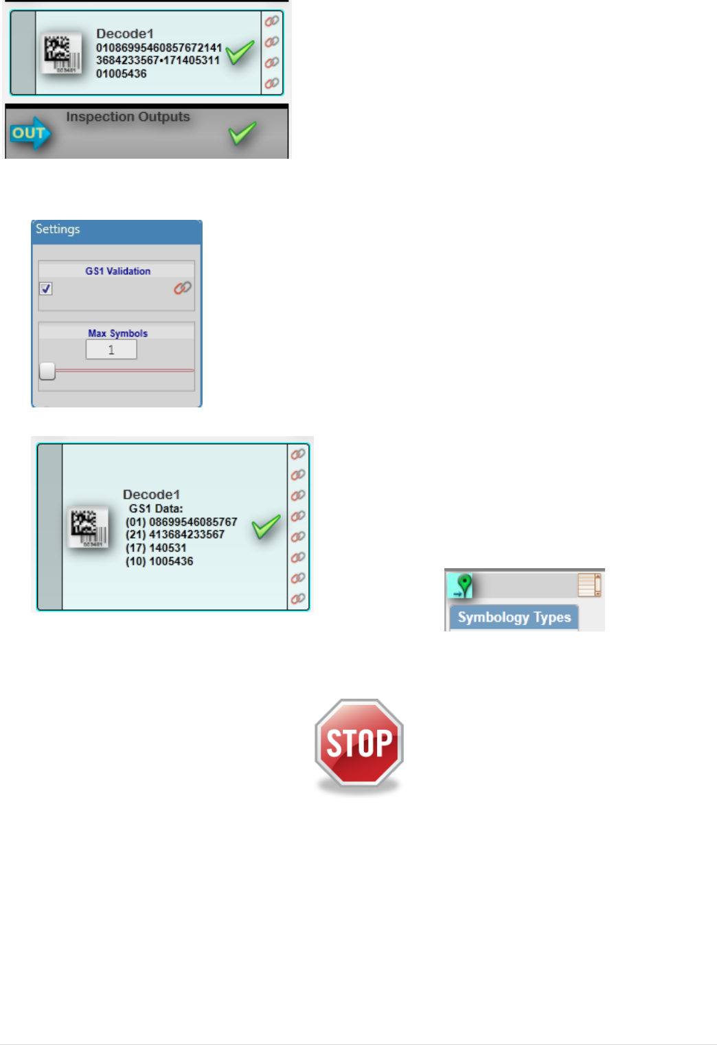
6. Observe the decoded data in the tool
7. Enable “GS1 validation” on the decode tool
8. Go to Run mode and observe the GS1 field parsing. Find the wrong one!
9. Enable the locator function on the decode tool
10. Save the job on your computer, but keep it open
End of this lab
6 | © 2 0 1 3 M i c r o s c a n S y s t e m s , I n c .
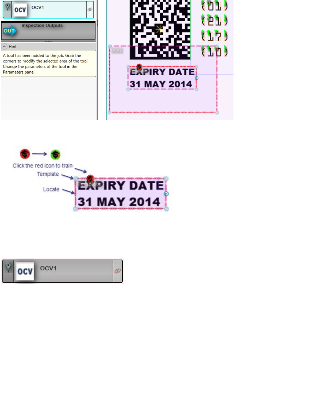
Lab2: using OCV for checking the expiry date and logo
1. Insert an OCV tool into your job on image 1.
2. Size the ROI around the expiry date
3. Resize the training window to include the text to check only
4. Train the tool by pressing the train button
5. Make the search ROI big enough to allow the text to be located with “AutoFind”
on all images.
6. Disable the locate function on the tool so it does not move with the decode tool
7. Click on the tool name and rename it to “Expiry OCV”
8. Run through the images in edit mode until you see OCV fail
© 2 0 1 3 M i c r o s c a n S y s t e m s , I n c . | 7
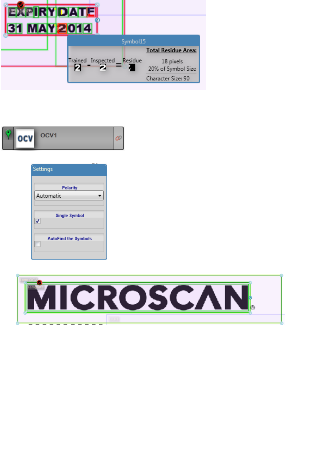
9. Look at the failed character and residue by clicking on it
10. Insert a second OCV tool and rename it to “Logo OCV”
11. Ensure that it relocates with the decode tool
12. Enable single symbol and disable Autofind
13. Train the OCV tool on the Microscan logo
8 | © 2 0 1 3 M i c r o s c a n S y s t e m s , I n c .
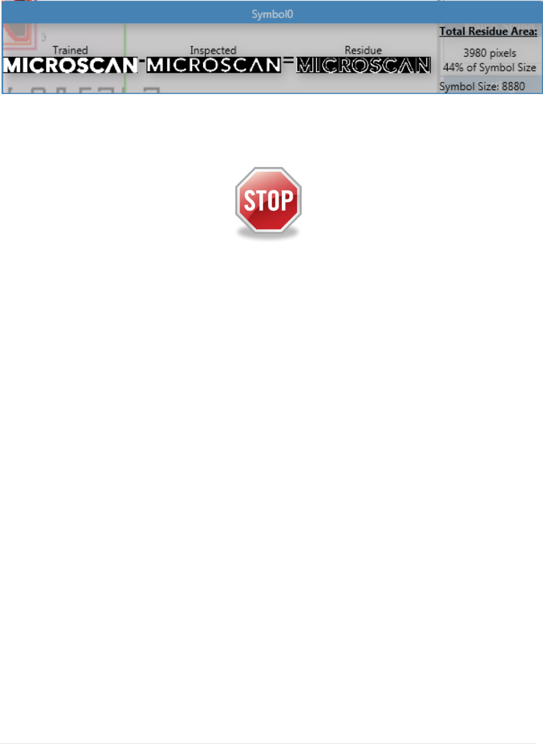
14. Run through the images and find the bad logo
15. View the residue by clicking on it
16. Save the job on your computer, but keep it open
End of this lab
© 2 0 1 3 M i c r o s c a n S y s t e m s , I n c . | 9
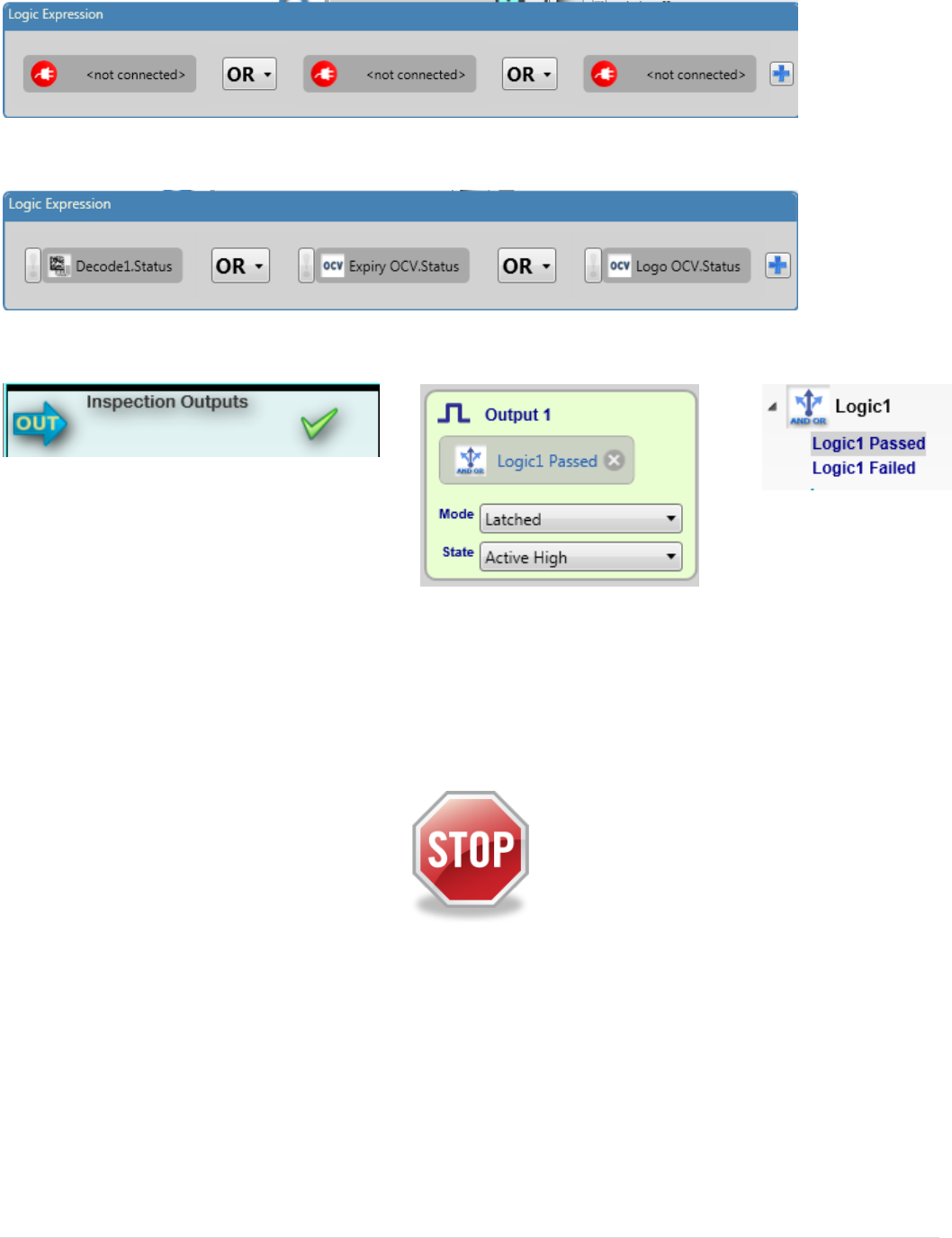
Lab3: using the Logic tool
1. Insert a logic tool into your job on image 1.
2. Create an expression with three values and OR as an operator:
3. Connect the values to the status of the decode and both OCV tools
4. Setup a hardware output on the logic tool passing
5. Run through the images and observe that the Logic tool (and output) passes
when at least one out of three tools passes
6. Save the job on your computer, but keep it open
End of this lab
10 | © 2 0 1 3 M i c r o s c a n S y s t e m s , I n c .
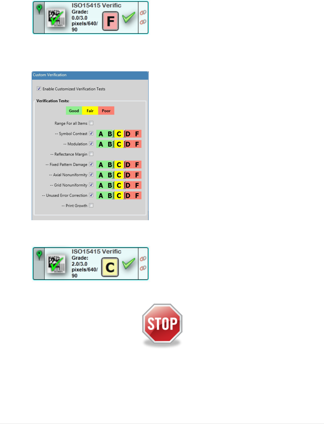
Lab4: verifying the 2D symbol
1. Insert a Verification tool into your job on image 1
2. Resize the ROI around the 2D code
3. Press the grade on the tool and watch the verification report
4. Run through the images and watch the report
5. Enable custom verification and omit reflectance from the grade
6. Run through the images again and observe the changed overall grade
7. Save the Job to your computer, but keep it open
End of this lab
© 2 0 1 3 M i c r o s c a n S y s t e m s , I n c . | 11
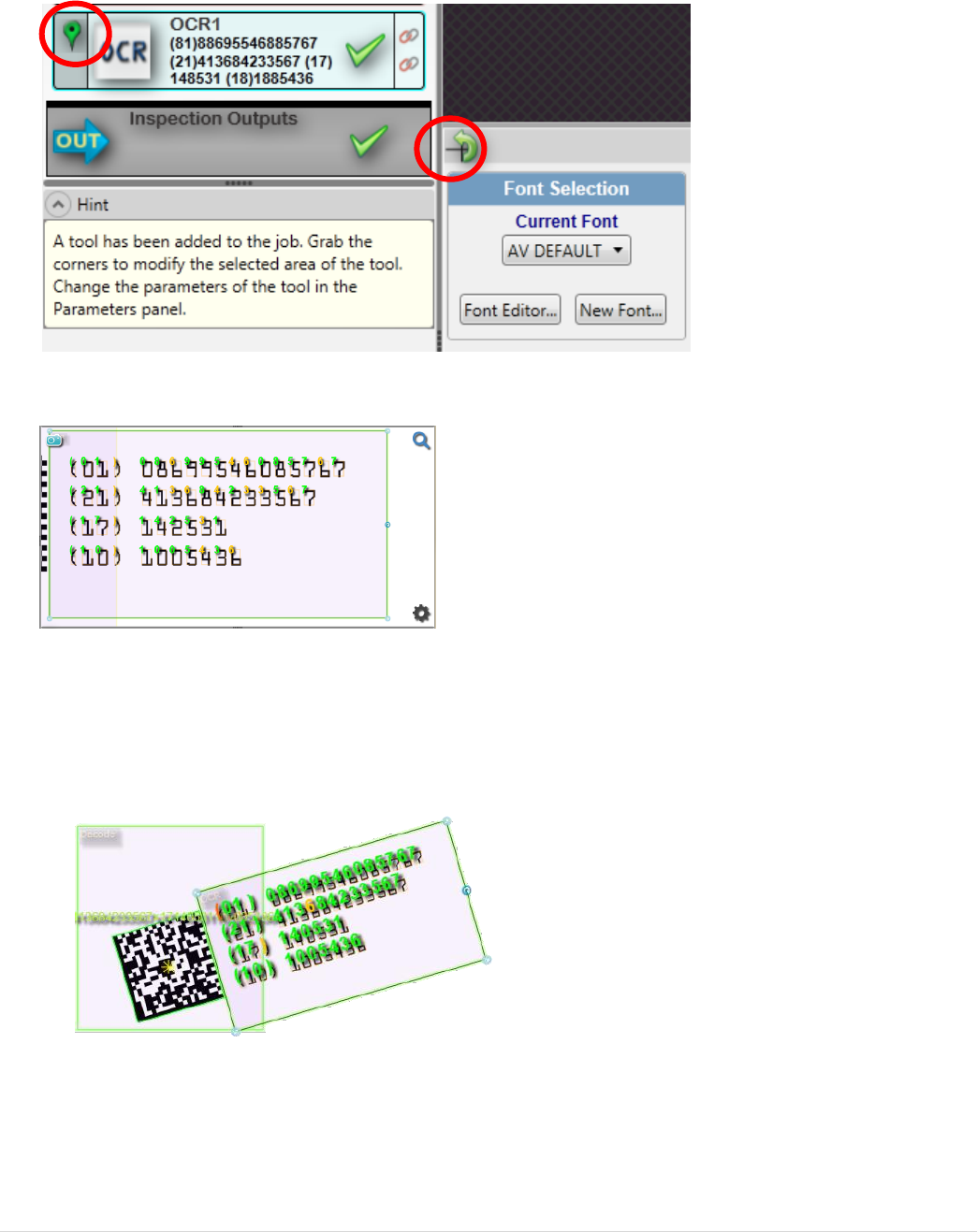
Lab5: using Microscan link to match data
1. Add a Read OCR tool and adjust the ROI over the printed text
(Tip: Don’t make the OCR tool ROI too small!)
2. Enable rotation and location on the OCR tool so that it will rotate along with the
symbol
3. Compare the read text to the printed text; add characters to the font library if
necessary
4. Run through the images to make sure the OCR re-locates correctly with the
decoded Data Matrix
12 | © 2 0 1 3 M i c r o s c a n S y s t e m s , I n c .
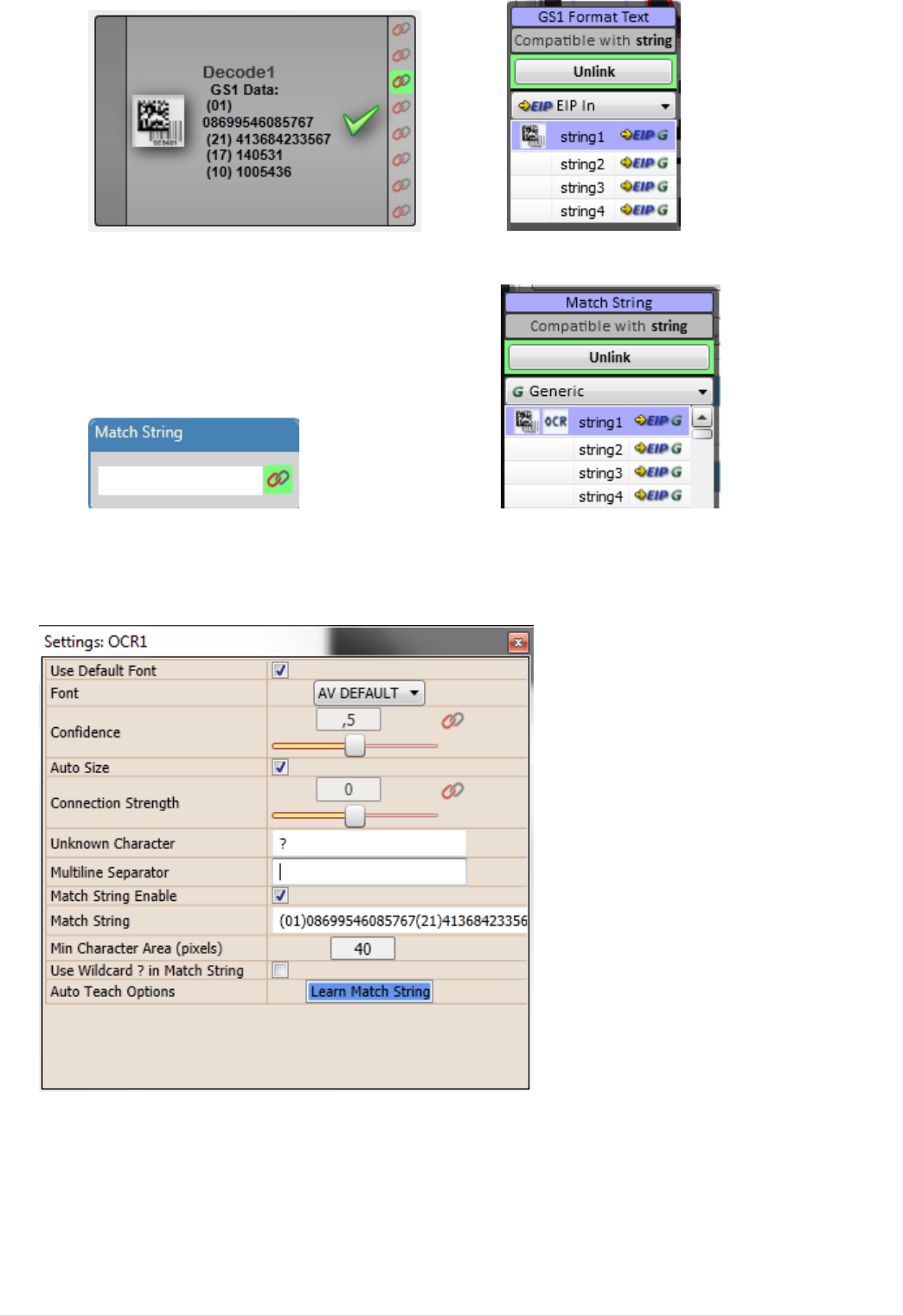
5. Link the decode tool GS1 formatted text output to “string 1”
6. Link the OCR match code to “string 1”
7. Remove the OCR multiline separator space in advanced settings (press
backspace and enter):
© 2 0 1 3 M i c r o s c a n S y s t e m s , I n c . | 13
8. You have now created a link between the symbol tool and OCR match input
and to compare the symbol to the human readable
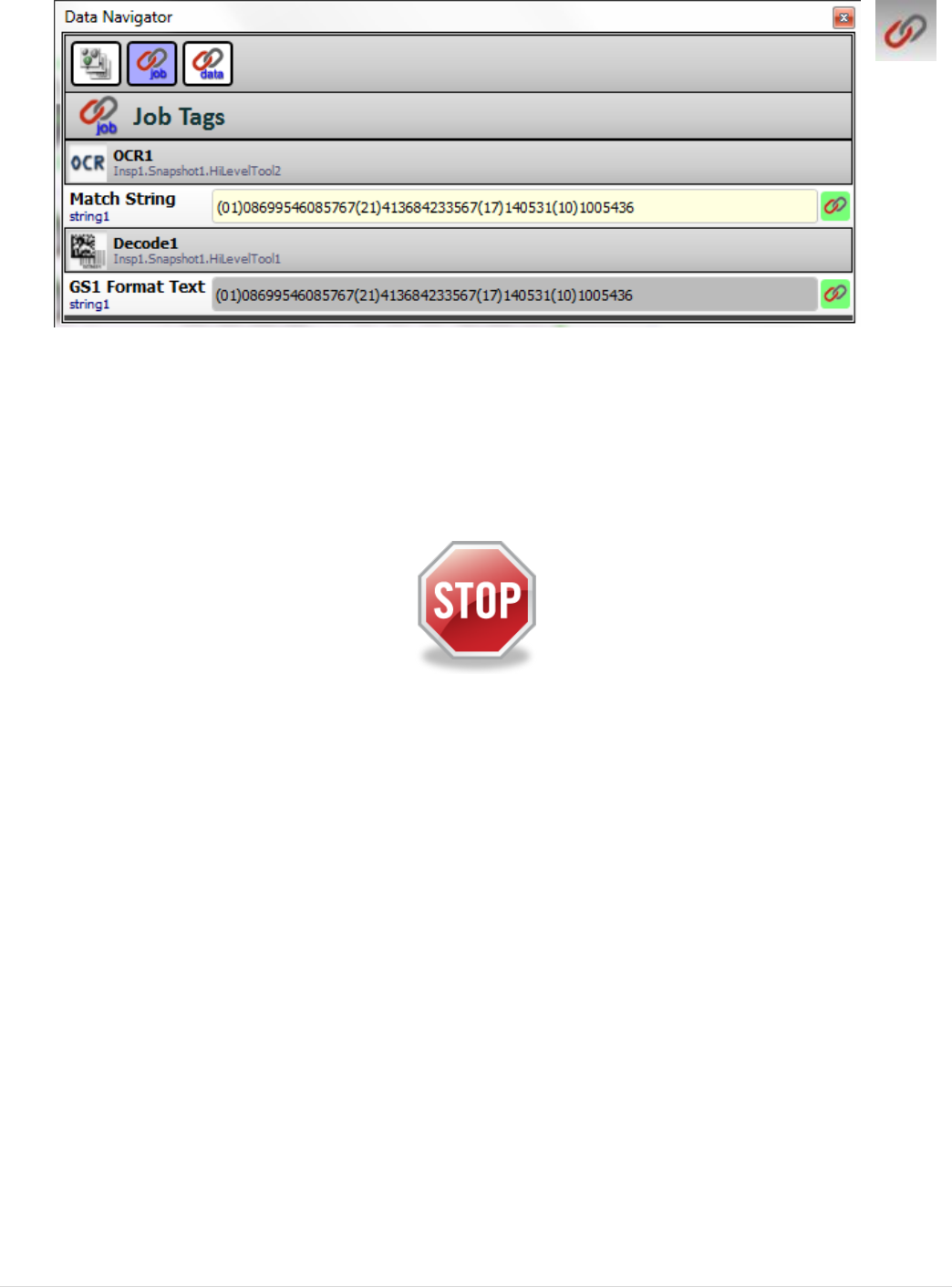
9. Step through the images. Is the human readable always correct?
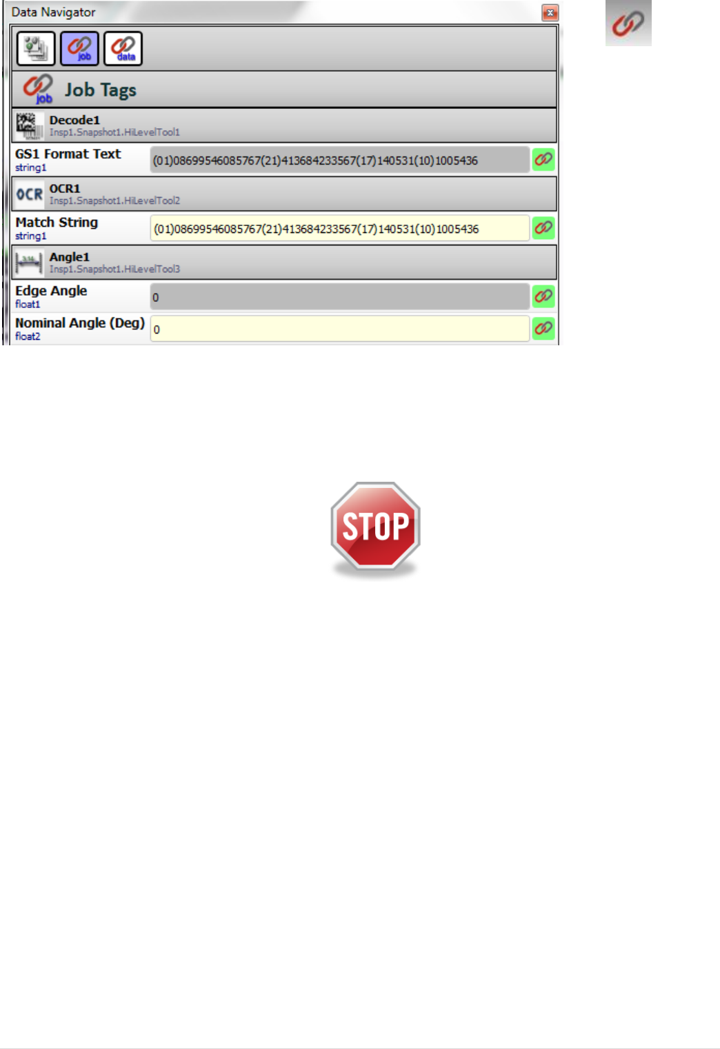
10. Open the data navigator and select job to observe the values
11. Explore the other two data navigator views
12. Go to Run mode
13. Refresh the tag list and repeatedly update the values in the Data navigator and
observe the changes
14. Save the job on your computer, but keep it open
End of this lab
14 | © 2 0 1 3 M i c r o s c a n S y s t e m s , I n c .
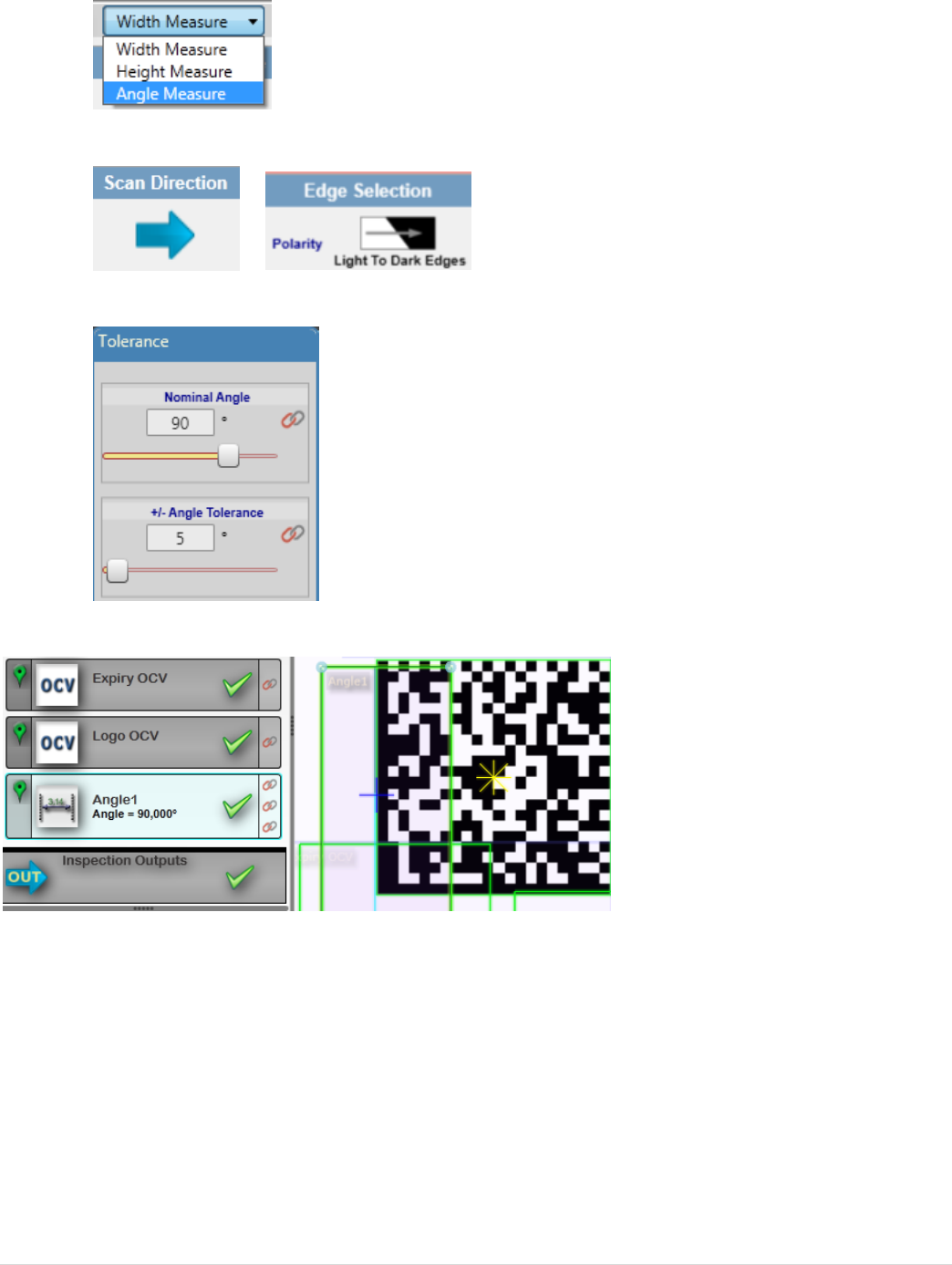
Lab6: using Microscan link to change data
1. Insert a Measurement tool into your job on image 1.
2. Resize the ROI around the left side of the 2D code
3. Select “angle measurement”
4. Set scan direction to “left to right” and edge polarity to “Light to dark”
5. Set the nominal angle to 90 degrees and select a tolerance
6. Run the angle tool and observe the angle
7. Link the Angle tool edge angle output to float 1
8. Link the Angle tool nominal input to float 2
© 2 0 1 3 M i c r o s c a n S y s t e m s , I n c . | 15
15. Open the data navigator and select job
16. Go to run mode and refresh the data navigator view
17. Change the nominal angle in the data navigator and observe the effect
18. Try to make the rotated code pass
19. Save the job on your computer, but keep it open
End of this lab
16 | © 2 0 1 3 M i c r o s c a n S y s t e m s , I n c .
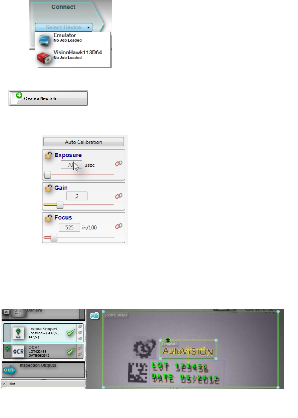
Lab7: using Job change (requires a live camera)
1. Open AutoVISION™ and select the Camera.
2. Create a new Job.
3. In image view, use Auto Calibration or adjust gain, focus and exposure to create
a crisp image.
4. Click on edit and insert a locate tool
5. Train the locate tool on the “AutoVISION” text
6. Insert an OCR tool to read the date and LOT code. Add characters to the font
where needed.
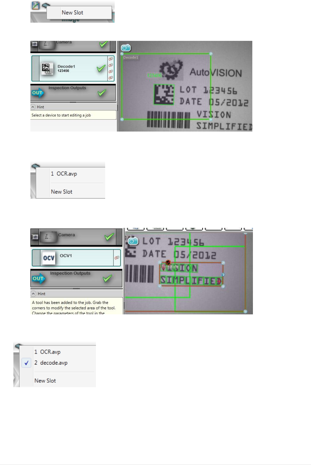
7. Save the job as ocr.avp and go to run mode to test the job
8. Go back to edit mode and save the job in flash by creating a new slot
© 2 0 1 3 M i c r o s c a n S y s t e m s , I n c . | 17
9. Go back to edit mode and create a new job with a decode tool
10. Save the job as decode.avp
11. Save the job in flash by creating a new slot
12. Go back to edit mode and create a new job with an OCV tool trained on “Vision
Simplified”
13. Save the job as ocv.avp
14. Save the job in flash by creating a new slot
15. Go to the connect screen and verify that the unit is now loaded with three jobs
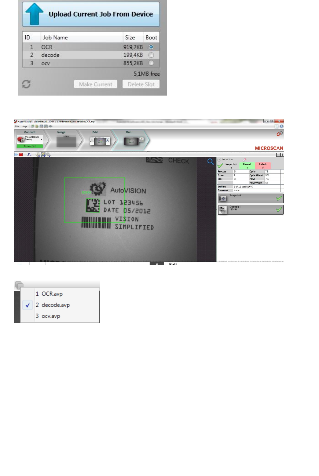
18 | © 2 0 1 3 M i c r o s c a n S y s t e m s , I n c .
16. Switch to the decode job by selecting it and making it the current job
`
17. Select job 3 from the drop down list to switch to OCV mode
18. Observe the job switching to OCV at runtime
© 2 0 1 3 M i c r o s c a n S y s t e m s , I n c . | 19
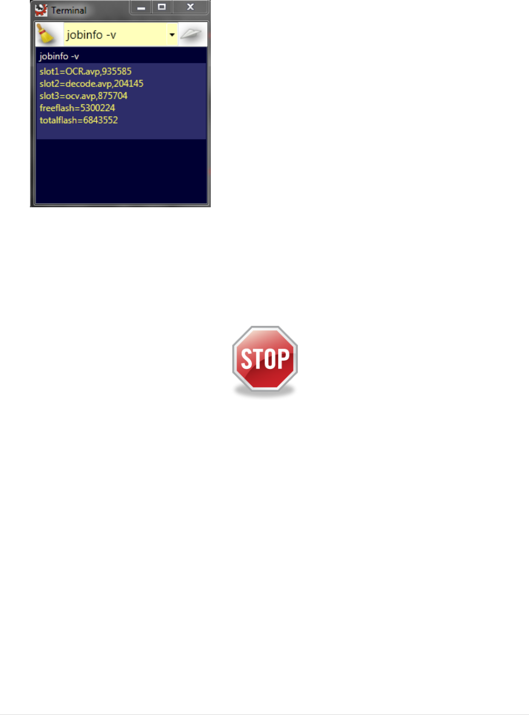
19. Open the terminal by pressing “Control T” to emulate job changeover by
command
20. Check available jobs by entering “jobinfo –v”
21. Check what job is running now by entering “get system.jobslot”
22. Now change to job1 by entering “jobload 1 –r” and observe the camera switch
to the OCR job.
End of this lab
20 | © 2 0 1 3 M i c r o s c a n S y s t e m s , I n c .
Lab8: setting gain and exposure via Microscan LINK
1. Open OCR.avp and go to the image view
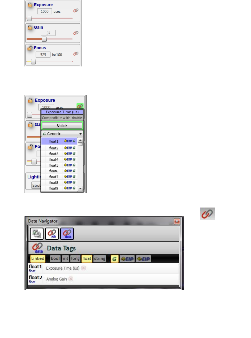
2. Lock the gain and exposure so they can be controlled via Microscan LINK
3. Link Exposure to float1 and gain to float2 using the Microscan LINK button next
to the parameter
4. Open the data navigator, select “data”, disable “bool” and enable “float” and
“linked” to review linked parameters
5. Go to run mode, but keep the data navigator open
6. Press “refresh tag list” and “refresh values” to see current photometry settings
© 2 0 1 3 M i c r o s c a n S y s t e m s , I n c . | 21
7. Change the values and observe the effect on the image
8. Go back to edit mode
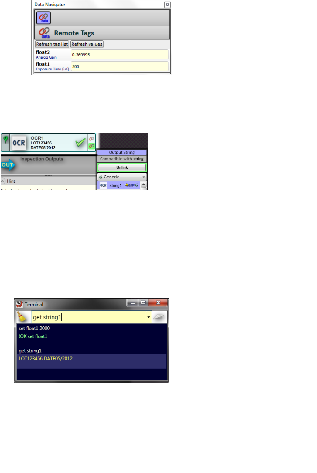
9. Link the OCR status to bool1 Microscan LINK button
10. Link the OCR output string to string1 by pressing the Microscan LINK button
11. Save the Job to your computer, but keep it open
12. Go to run mode, open the data navigator and view the values. Don’t forget to
refresh values!
13. Close the data navigator
14. Open the terminal by entering “Control T”
15. Experiment with changing the gain and exposure via Microscan LINK using the
“set floatn” command
16. Experiment querying results via Microscan LINK using the “get booln” and get
“get stringn” commands.
22 | © 2 0 1 3 M i c r o s c a n S y s t e m s , I n c .
Lab9: using the web HMI
1. Open OCR.avp and go to edit mode
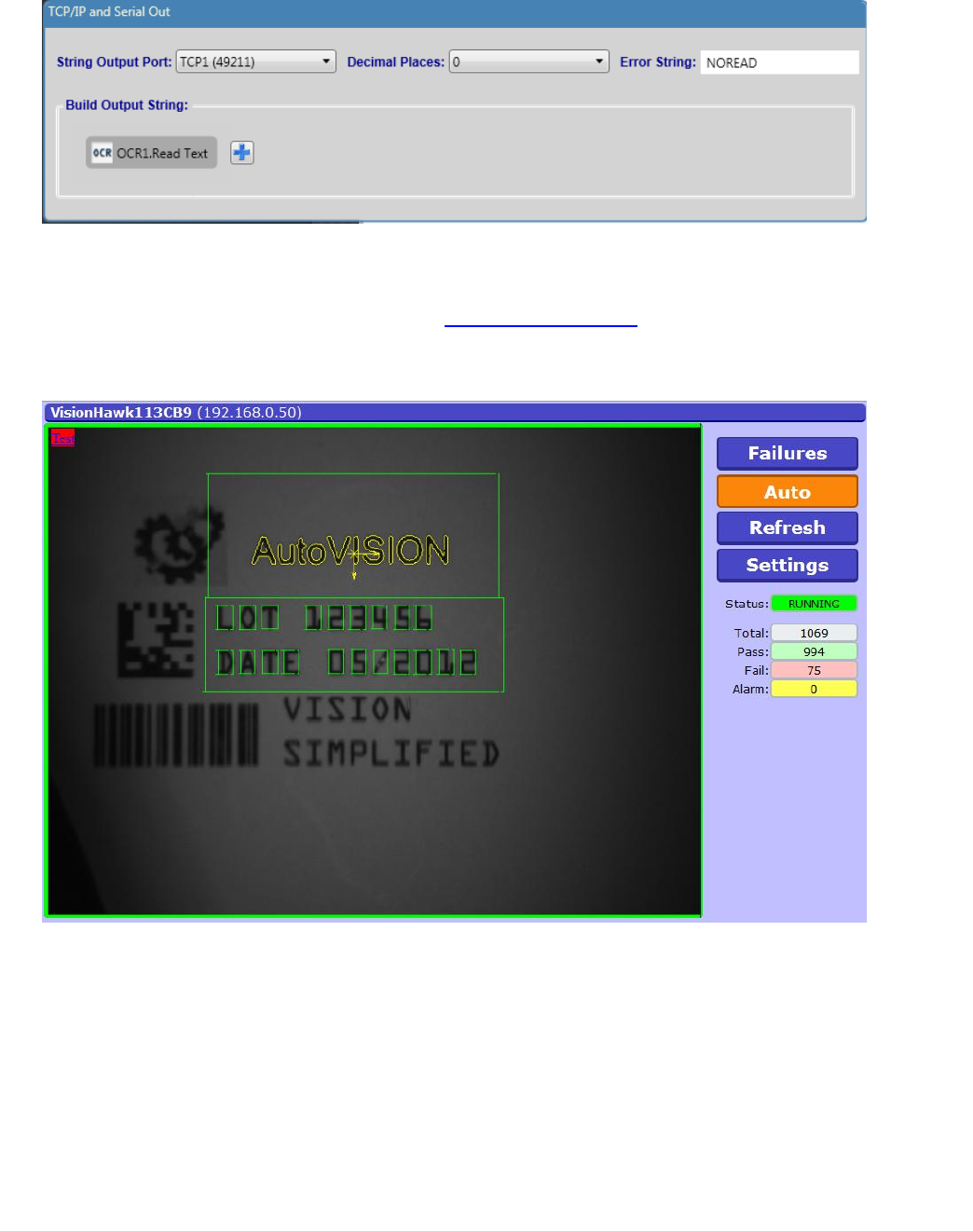
2. Open the inspection outputs and build an output string linked to the OCR output
string
3. Change the Error String field to “NOREAD”
4. Save the Job to your computer, but keep it open
5. Go to run mode and close AutoVISION, leaving the camera running
6. Open your web browser and enter http://ip_address in the address bar, using
the IP address of your camera, e.g. http://192.168.0.10
7. View the default web HMI page
8. Select failures and observe the last failed image freezing
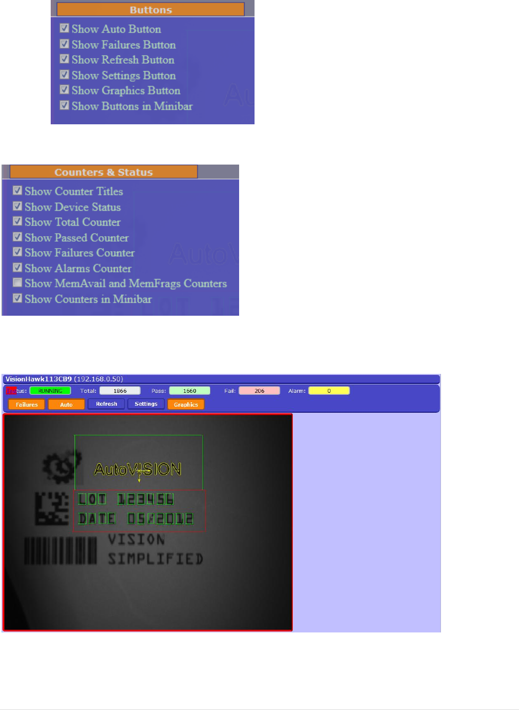
© 2 0 1 3 M i c r o s c a n S y s t e m s , I n c . | 23
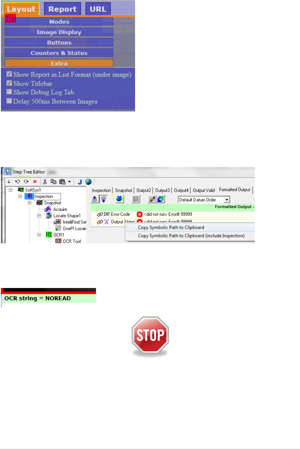
9. Now customize your web page by clicking “Settings”
10. Browse through the options to see what the options are
11. Under “Layout”/ “Buttons”, enable all options:
12. Under “layout”/ “Counters & Status” enable “Show counters in Minibar”
13. Press “Save” and close the settings window
14. View the modified layout
Adding functions: Using the web HMI to view parameters
15. Open settings again and open the report tab to add output parameters
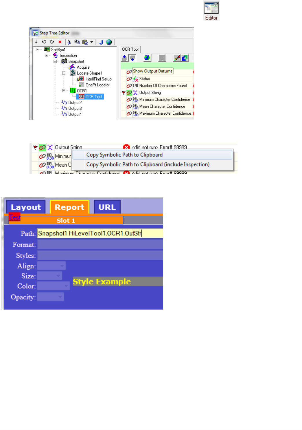
24 | © 2 0 1 3 M i c r o s c a n S y s t e m s , I n c .
16. Select “Slot1” to add a first parameter
17. Now open Visionscape Frontrunner and select “SoftSys”
18. Open the OCR.avp job and open the editor
19. Navigate to the OCR tool output parameters
20. Right click on the “Output string” and select “Copy symbolic Path to Clipboard”
21. Go back to the web browser and paste the link in the path field for Slot1
© 2 0 1 3 M i c r o s c a n S y s t e m s , I n c . | 25
22. Setup the message format by typing “OCR string = %s” in the format field
23. Setup the message style by adjusting the style options via the selection lists
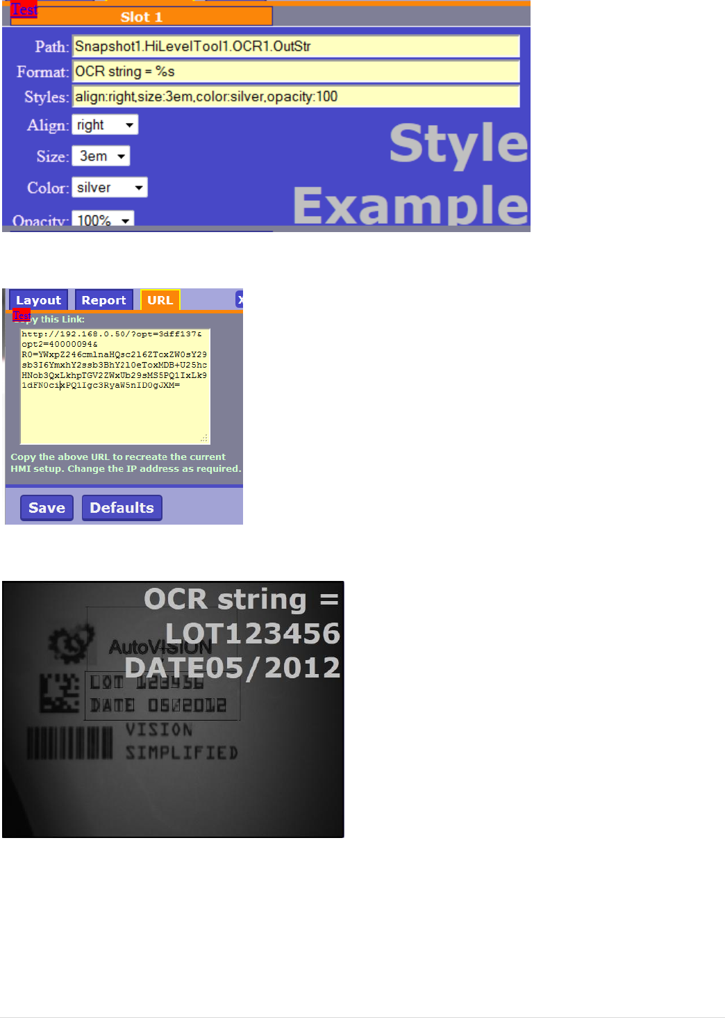
24. Select the URL tab and copy the link in the window
25. Paste the link into your browser address bar and view the parameter output
26. Open the settings page again, go to “Layout/extra” and enable “Show report in
list format”
26 | © 2 0 1 3 M i c r o s c a n S y s t e m s , I n c .
27. Close the setup screen and observe the new position of the text
28. Make the OCR read fail. Observe that old data is output when the OCR tool fails
29. In Frontrunner, go to “Inspection” / “Formatted output” and copy “Output String”
to the clipboard
30. Paste the link into the path for Slot1 and press “Save”
31. Copy the new URL from the URL tab and paste it into the address bar
32. Observe the noread message when OCR fails
End of this lab
© 2 0 1 3 M i c r o s c a n S y s t e m s , I n c . | 27
Bonus lab1: Getting data out of the camera
1. Use the OCR.avp used with the HMI exercise
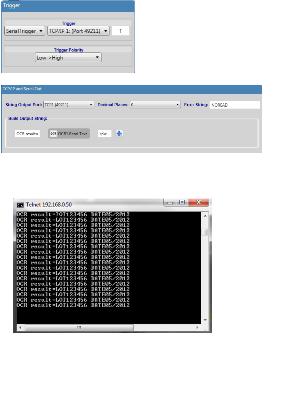
2. Under the Camera step, set the trigger to SerialTrigger, and use TCP port
49211
3. Amend the output message to show more than just the OCR text .
4. Run the Job
5. Telnet to your ip port 49211, e.g. telnet 192.168.0.10 49211
6. Send T to trigger
28 | © 2 0 1 3 M i c r o s c a n S y s t e m s , I n c .
Enabling Telnet on Windows 7
From the Microscan Community blog
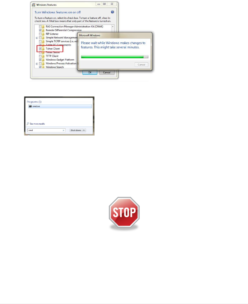
1. Select Start > Control Panel > Programs > Programs and Features
2. Select Turn Windows Features on or off from the left pane.
3. In the Features box, check the box next to Telnet client, then click OK; and the
feature will install.
4. To use Telnet, enter the command prompt (just type cmd in the search box)
5. In the command prompt, type telnet to launch, or telnet (IP) (PORT) to connect
directly to a device.
Example: telnet 127.0.0.1 49211
End of this lab
