HI BRITE Series Illuminator Configuration Guide Hibriteconfigguide
2010-10-11
: Microscan Hibriteconfigguide hibriteconfigguide 824598d5-029e-4263-886b-516ea50dd088 _att
Open the PDF directly: View PDF ![]() .
.
Page Count: 2
Copyright ©2010 Microscan Systems, Inc. 83-230016 Rev B
2
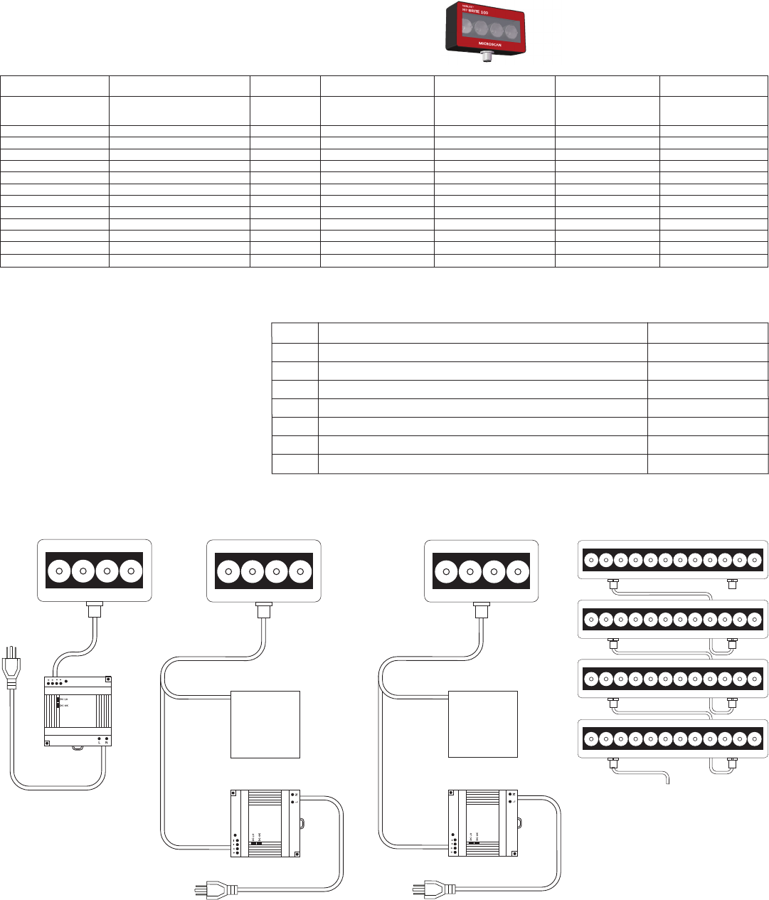
Figure A
Hi-Brite Series Illuminator
with power supply
Figure D
Hi-Brite Series Illuminators in
a daisy chain conguration.
See gures A, B, or C for the
correct power supply and
signal connections for your
application.
Hardware Required
Item Description Part Number
1 Hi-Brite Series Lights NER-011660XXXG
2 Power Supply DSP100 24VDC 4.2A DIN Mount 97-000006-01
2 Power Supply DSP60 24VDC 2.5A DIN Mount NER-011504100
3 Cable, 5P M12 Female To Flying Leads, 3M 61-000186-01
3 Cable, 5P M12 Female To Flying Leads, 5M 61-000187-01
4 Cable, 5P M12 Male To 5P M12 Female, 1M 61-000184-01
4 Cable, 5P M12 Male To 5P M12 Female, 3M 61-000185-01
Hi-Brite Series Illuminators
Conguration Guide
Continuous Mode
Continuous Mode With Dimming
Or On-Off Control High Output Strobe Mode Daisy Chain, All Modes
PART NUMBER DESCRIPTION
Current Draw @
24VDC (typ.)
No Controller Required
(Can Be Connected Directly
To 24VDC)
No Controller Required
(Can Be Connected Directly
To 24VDC)
No Controller Required
(Can Be Connected Directly
To 24VDC)
No Controller Required
(Can Be Connected Directly
To 24VDC)
NER-011660100G Hi-Brite 45 Red 10 Degree 75mA Figure A Figure B Figure C Not Applicable
NER-011660101G Hi-Brite 45 Red 50 Degree 75mA Figure A Figure B Figure C Not Applicable
NER-011660110G Hi-Brite 45 White 10 Degree 75mA Figure A Figure B Figure C Not Applicable
NER-011660111G Hi-Brite 45 White 50 Degree 75mA Figure A Figure B Figure C Not Applicable
NER-011660200G Hi-Brite 100 Red 10 Degree 275mA Figure A Figure B Figure C Not Applicable
NER-011660201G Hi-Brite 100 Red 50 Degree 275mA Figure A Figure B Figure C Not Applicable
NER-011660210G Hi-Brite 100 White 10 Degree 275mA Figure A Figure B Figure C Not Applicable
NER-011660211G Hi-Brite 100 White 50 Degree 275mA Figure A Figure B Figure C Not Applicable
NER-011660300G Hi-Brite 300 Red 10 Degree 750mA Figure A Figure B Figure C Figure D
NER-011660301G Hi-Brite 300 Red 50 Degree 750mA Figure A Figure B Figure C Figure D
NER-011660310G Hi-Brite 300 White 10 Degree 750mA Figure A Figure B Figure C Figure D
NER-011660311G Hi-Brite 300 White 50 Degree 750mA Figure A Figure B Figure C Figure D
Figure B
Hi-Brite Series Illuminator
with customer supplied
dimming or on-off
signal source
Figure C
Hi-Brite Series Illuminator
with customer supplied
strobe trigger signal source
33 3
3
4
4
4
Customer
supplied
signal source
Customer
supplied
signal source
111
2
2
1
Copyright ©2010 Microscan Systems, Inc. www.microscan.com
HI-BRITE Series Illuminators
Accessories
Description Part Number Application
AC Power Cord US NER-030028300 Power Cord For Power Supply
AC Power Cord EU NER-030028400 Power Cord For Power Supply
AC Power Cord UK NER-030028500 Power Cord For Power Supply
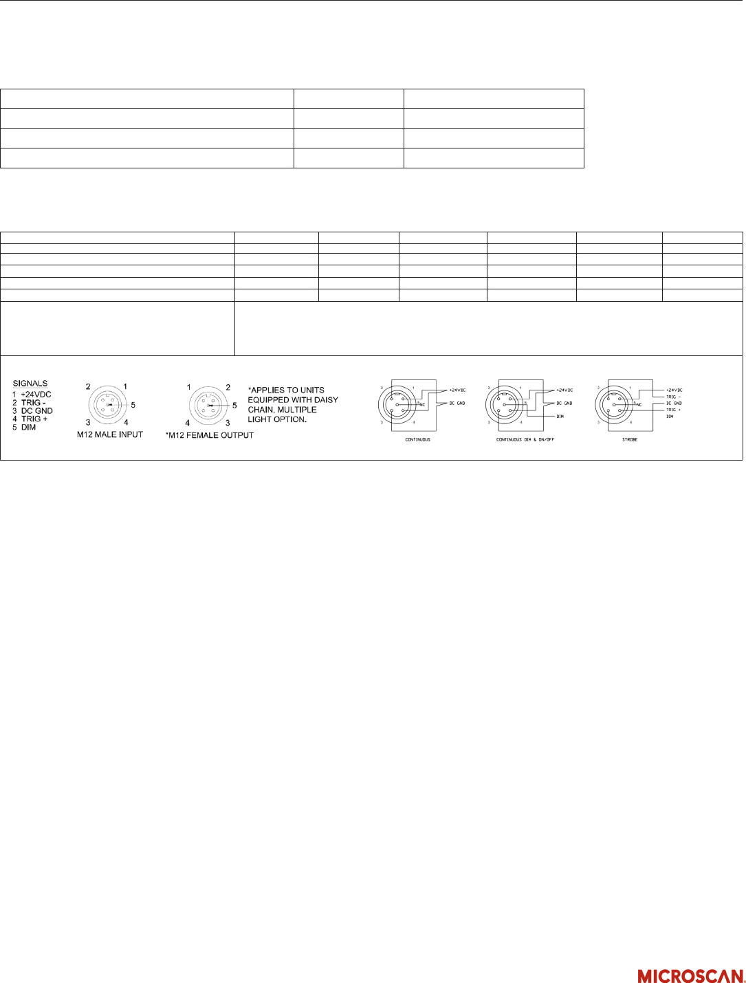
Connections:
Input Connector (M12 Male, 5 Circuit, A-Code) Pin 1 Pin 2 Pin 3 Pin 4 Pin 5 Backshell
Continuous Mode (Figure A): +20.2-28.8VDC DC GND DC GND +20.2-28.8VDC No Connection Shield
Continuous Mode With Dimming (Figure B): +20.2-28.8VDC DC GND DC GND & DIM (-) +20.2-28.8VDC Dim (+) Shield
Continuous Mode With On-Off Control (Figure B): +20.2-28.8VDC DC GND DC GND & DIM (-) +20.2-28.8VDC Dim (+) Shield
High Output Strobe Mode (Figure C): +20.2-28.8VDC TRIG (-) DC GND TRIG (+) No Connection Shield
Daisy Chain, All Modes, Hi-Brite 300 Only (Figure D):
Note: The Output (Daisy Chain) Connector (M12 Female, 5 Circuit, A-Code) has an identical pin out to the Input Connector.
The Output (Daisy Chain) Connector passes through any signal applied to the Input Connector. Do not attempt to connect
more than a total of four lights in a daisy chain conguration. The 24VDC power supply’s maximum current rating must
be greater than or equal to the combined total current draw of all lights connected in the daisy chain.
Control Signals
DIM (Continuous Mode With PWM Dimming):
0VDC (LEDs off) to 3.1-3.5VDC (LEDs on) pulse width modulated (PWM) signal , <1mA, Modulation Frequency 2KHz +/- 100Hz
Note: When using Continuous Mode With Dimming, the LED duty cycle will equal the duty cycle of the dimming signal.
DIM (Continuous Mode With On-Off Control): 0VDC (LEDs off), 3.1-3.5VDC (LEDs on), (<1mA)
TRIG (High Output Strobe Mode):
optoisolated, 0VDC (LEDs off) to 3.1-28.8VDC (LEDs on), 10mA max, 20 µs min Trigger pulse width. Note: High Output Strobe internally limits LED frequency and pulse
width to a maximum of 90Hz and 1mS respectively. Light output pulse will follow Trigger pulse width from 20 µs to 1ms.
Cable Specications:
Wire colors for ying lead cables:
Pin 1 = Brown
Pin 2 = White
Pin 3 = Blue
Pin 4 = Black
Pin 5 = Gray
Connector Nut = Shield
Note: Non-Microscan cables may use different wire colors. It is the customer’s responsibility to make sure the light is connected correctly per the pin numbers in
the table above.
Tel: 603 598 8400 Fax: 603 577 5976 www.microscan.com/nerlite04-000575-01 REV: A
***CAUTION***
BEFORE CONNECTING LIGHT,
VERIFY POWER SUPPLY IS
APPROPRIATE PER THE VOLTAGE
AND CURRENT SPECIFIED ON THE
PRODUCT LABEL.
FOR ADDITIONAL INFORMATION
OR PRODUCT OFFERINGS VISIT:
WWW.MICROSCAN.COM/NERLITE
Affix peel and stick eye safety
label to a system location
visible to system operators
and supporting personnel.
