MicroHAWK MV 20 / 30 40 Smart Camera Guide Microhawkmvguide
2017-12-15
: Microscan Microhawkmvguide microhawkmvguide center
Open the PDF directly: View PDF ![]() .
.
Page Count: 108 [warning: Documents this large are best viewed by clicking the View PDF Link!]
- MicroHAWK MV-20 / MV-30 / MV-40 Smart Camera Guide
- Contents
- PREFACE Welcome
- CHAPTER 1 Introduction
- CHAPTER 2 System Components
- CHAPTER 3 Getting Started with AutoVISION
- CHAPTER 4 Optics and Lighting
- APPENDIX A Connector Pinouts
- APPENDIX B Cable Specifications
- APPENDIX C General Specifications
- APPENDIX D Serial Commands
- APPENDIX E USB Power Management (MV-20 and MV-30)
- APPENDIX F TCP/UDP and General Port Usage
MicroHAWK MV-20 / MV-30 / MV-40
Smart Camera Guide
84-9007432-02 Rev B
Copyright ©2017
Omron Microscan Systems, Inc.
Tel: +1.425.226.5700 / 800.762.1149
Fax: +1.425.226.8250
All rights reserved. The information contained herein is proprietary and is provided solely for the purpose of
allowing customers to operate and/or service Omron Microscan manufactured equipment and is not to be
released, reproduced, or used for any other purpose without written permission of Omron Microscan.
Throughout this manual, trademarked names might be used. We state herein that we are using the names to the
benefit of the trademark owner, with no intention of infringement.
Disclaimer
The information and specifications described in this manual are subject to change without notice.
Latest Manual Version
For the latest version of this manual, see the Download Center on our web site at: www.microscan.com.
Technical Support
For technical support, e-mail:
Americas_support@microscan.com
EMEA_support@microscan.com
APAC_support@microscan.com
China_support@microscan.com
Warranty
For current warranty information, see: www.microscan.com/warranty.
Omron Microscan Systems, Inc.
United States Corporate Headquarters
+1.425.226.5700 / 800.762.1149
United States Northeast Technology Center
+1.603.598.8400 / 800.468.9503
European Headquarters
+31.172.423360
Asia Pacific Headquarters
+65.6846.1214
Statements of Compliance
CE Class A
MicroHAWK Smart Cameras have passed Class A testing for the standards listed below, including U.S. (FCC), European
(EN), and Canadian EMC requirements (ICES).
• 2011/65/EU
• EN 50581:2012
• 2004/108/EC
• EN 55022:2010 For Class A Products
• EN 55024:2010, including:
• IEC 61000-4-3:2010
• IEC 61000-4-4:2012
• IEC 61000-4-5:2014
• IEC 61000-4-6:2013
• IEC 61000-4-8:2009
• IEC 61000-4-11:2004
• EN 61000-3-2:2014
• EN 61000-3-3:2013
• FCC 15.109:2015 For Class A Products
• FCC 15.107:2015 For Class A Products
• ICES-003:2012 For Class A Products
CE Class B
MicroHAWK Smart Cameras have passed Class B testing for the standards listed below, including U.S. (FCC), European
(EN), and Canadian EMC requirements (ICES). The MicroHAWK had a ferrite core installed on the USB cable adjacent to the
MV-20 for all tests. The ferrite used was classified as a lower and broadband part for frequencies in the range of 1-300 MHz.
• 2011/65/EU
• EN 50581:2012
• 2004/108/EC
• EN 55022:2010 For Class B Products
• EN 55024:2010, including:
• IEC 61000-4-3:2010
• IEC 61000-4-4:2012
• IEC 61000-4-5:2014
• IEC 61000-4-6:2013
• IEC 61000-4-8:2009
• IEC 61000-4-11:2004
• EN 61000-3-2:2014
• EN 61000-3-3:2013
• FCC 15.109:2015 For Class B Products
• FCC 15.107:2015 For Class B Products
• ICES-003:2012 For Class B Products
EMC
ESD
Electromagnetic compatibility (EMC) exception: The MicroHAWK was tested for electrostatic discharge immunity per IEC
61000-4-2.
The following conditions and exclusions apply for proper use of the MicroHAWK and for ESD immunity as it
applies to the overall system in which the MicroHAWK is integrated. The MicroHAWK is not intended for stand-alone
functionality and is meant to function as part of a larger system. Per paragraph 8.3.2 of IEC 61000-4-2, sections A and C:
A.) Points and surfaces that are only accessible by maintenance.
Justification: The MicroHAWK is approved for use when installed as a component and when it is no longer accessible to the
end user except at the time of installation or when maintenance is performed. The MicroHAWK may be accessed for
maintenance provided that proper ESD handling procedures are followed.
C.) Points or surfaces of equipment that are no longer accessible after fixed installation.
Justification: The MicroHAWK is installed as a component in a system and the device is no longer accessible.
The end user should be trained in ESD safety and handling. The system in which the MicroHAWK is installed should be
properly grounded for power ground and earth ground. The MicroHAWK should not be placed next to devices that build up
excessive static charge.

Statements of Compliance
FCC
MicroHAWK MV-20, MV-30, and MV-40 Smart Cameras have been tested for compliance with
FCC (Federal Communications Commission) requirements and have been found to conform to
applicable FCC standards.
To comply with FCC RF exposure compliance requirements, this device must not be co-located
with or operate in conjunction with any other antenna or transmitter.
Changes or modifications not expressly approved by the party responsible for compliance could
void the user’s authority to operate the equipment.
CE
MicroHAWK MV-20, MV-30, and MV-40 Smart Cameras have been tested for compliance with CE
(Conformité Européenne) requirements, and have been found to conform to applicable CE standards.
The CE Declaration of Conformity for this product is available from Microscan upon request.
MicroHAWK MV-20, MV-30, and MV-40 Smart Cameras have been tested by an independent
electromagnetic compatibility laboratory in accordance with the applicable specifications and
instructions.
UL
MicroHAWK MV-20, MV-30, and MV-40 Smart Cameras have been tested for compliance with UL
(Underwriters Laboratories) standards and guidelines, and have been found to conform to applicable
UL standards.
Restricted Substances
See www.microscan.com/quality for Microscan compliance statements related to all applicable
restricted substances.

Warning and Caution Summary
CAUTION: Viewing the MicroHAWK MV-20, MV-30, or MV-40 Smart Camera’s LED output with
optical instruments such as magnifiers, eye loupes, or microscopes within a distance of 100 mm
could cause serious eye injury.
CAUTION: Use of controls or adjustments or performance of procedures other than those specified
herein may result in hazardous radiation exposure.
WARNING
LED LIGHT
DO NOT VIEW DIRECTLY WITH OPTICAL INSTRUMENTS
CLASS 1 LED PRODUCT
LED Output: 625 nm

MicroHAWK MV-20 / MV-30 / MV-40 Smart Camera Guide vii
Contents
PREFACE Welcome ix
Purpose of This Manual ix
Manual Conventions ix
CHAPTER 1 Introduction 1-1
Product Summary 1-2
Features and Benefits 1-2
Applications 1-3
Package Contents 1-3
MicroHAWK MV-20, MV-30, and MV-40 Smart Camera Models 1-4
MicroHAWK MV Part Number Structure 1-6
CHAPTER 2 System Components 2-1
Hardware Components and Accessories 2-2
Label Information 2-4
Mechanical Dimensions 2-5
Cabling Configurations 2-12
Mounting the Camera 2-19
I/O Wiring 2-20
Grounding and Power 2-30
I/O Filtering and Debounce 2-32
Camera Definition File Example 2-33
Status Indicators 2-34

viii MicroHAWK MV-20 / MV-30 / MV-40 Smart Camera Guide
CHAPTER 3
CHAPTER 4
APPENDIX A
Getting Started with AutoVISION 3-1
Setting Up a Job in AutoVISION 3-2
PROFINET I/O and IP Address Assignment 3-9
Optics and Lighting 4-1
Optics 4-2
Illumination 4-5
Machine Vision Lighting Principles 4-6
MicroHAWK MV-40 External Illumination Control and Wiring 4-7
Connector Pinouts A-1
APPENDIX B
APPENDIX C
APPENDIX D
APPENDIX E
APPENDIX F
MV-20 Connector A-2
MV-30 Connector A-3
MV-40 Connector A-4
Cable Specifications B-1
MV-20 Cables B-2
MV-30 Cables B-3
MV-40 Cables B-8
General Specifications C-1
MV-20 General Specifications C-2
MV-30 General Specifications C-3
MV-40 General Specifications C-4
Serial Commands D-1
USB Power Management (MV-20 and MV-30) E-1
TCP/UDP and General Port Usage F-1
MicroHAWK Ports F-2

MicroHAWK MV-20 / MV-30 / MV-40 Smart Camera Guide ix
Preface
PREFACE Welcome
Purpose of This Manual
This manual contains detailed information about how to configure and operate
MicroHAWK MV-20, MV-30, and MV-40 Smart Cameras.
Manual Conventions
The following typographical conventions are used throughout this manual.
• Items emphasizing important information are bolded.
• Menu selections, menu items and entries in screen images are indicated as: Run
(triggered), Modify..., etc.

Preface
xMicroHAWK MV-20 / MV-30 / MV-40 Smart Camera Guide
MicroHAWK MV-20 / MV-30 / MV-40 Smart Camera Guide 1-1
1
Introduction
1
CHAPTER 1 Introduction
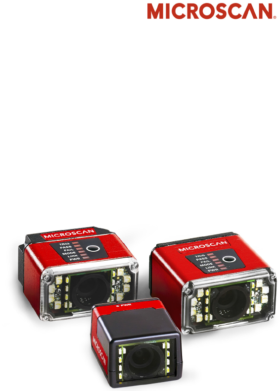
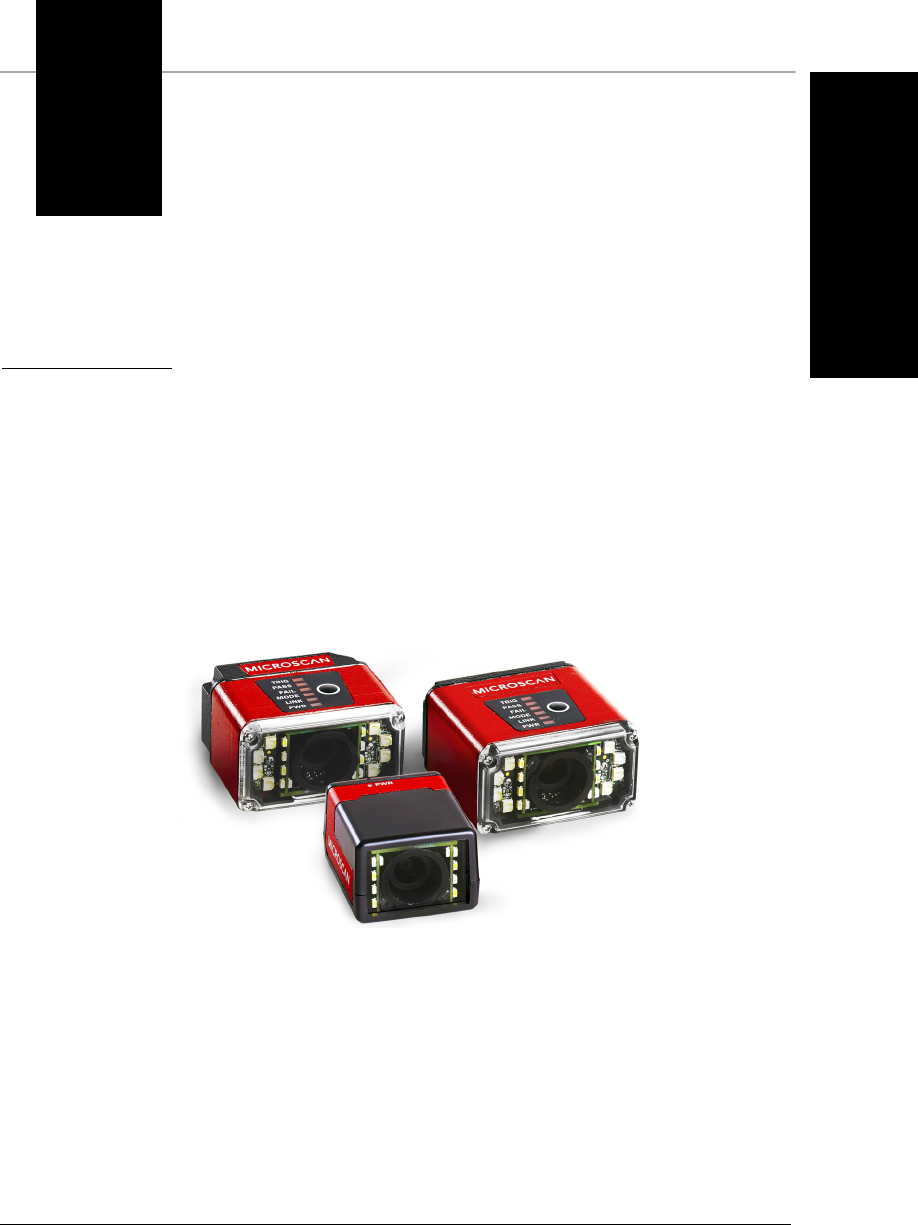
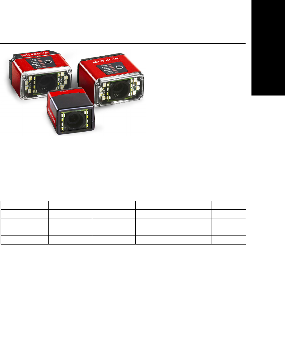
MicroHAWK MV-20, MV-30, and MV-40 Smart Cameras

Chapter 1Introduction
1-2 MicroHAWK MV-20 / MV-30 / MV-40 Smart Camera Guide
Product Summary
MicroHAWK MV-20, MV-30, and MV-40 Smart Cameras are designed for reliable vision
performance in embedded identification and inspection applications. As the world’s
smallest fully-integrated vision system, the MicroHAWK’s compact size and wide angle
optics provide the best performance available for machine vision tasks at close range.
The MicroHAWK MV-20, MV-30, and MV-40 allow OEM design engineers to implement
inspection, color matching, symbol decoding, OCR, and more, in a single compact
solution. The camera’s small form factor allows flexible positioning in tight spaces.
AutoVISION software, designed for use with the MicroHAWK MV-20, MV-30, and MV-40,
provides an intuitive interface, step-by-step configuration, and a library of presets that
allow easy setup and deployment. For more complex vision applications, the system can
be upgraded from AutoVISION to Visionscape.
Features and Benefits
• World’s smallest fully functional vision system
• Virtual Ethernet over USB (MicroHAWK Engine, MV-20 and MV-30)
• OEM-ready for easy integration
• Integrated lighting and flexible M12 fixed optics
• Flexible programming options for custom applications
• Simplified configuration with AutoVISION software

Applications
Introduction
1
MicroHAWK MV-20 / MV-30 / MV-40 Smart Camera Guide 1-3
Applications
• Inspection
• Guidance
• Gauging
• Part presence/absence
• Color detection and matching
• Medical device inspection
• Fiducial location
• Part location/orientation detection
• Packaging
• Robotics
• Auto ID (Data Matrix and other 2D symbologies, 1D, OCR)
• 1D and 2D Code Verification
• OCV (Optical Character Verification)
Package Contents
Before you install AutoVISION software and connect your MicroHAWK MV-20, MV-30, or
MV-40, please take a moment to confirm that the following items are available:
• A MicroHAWK MV-20, MV-30, or MV-40 Smart Camera.
• An active internet connection to download the latest AutoVISION software installer
from the Download Center on the Microscan website or a USB drive containing the
latest AutoVISION software installer.
• A Micro-USB Type B-to-USB Type A cable (not included).
Chapter 1Introduction
1-4 MicroHAWK MV-20 / MV-30 / MV-40 Smart Camera Guide
MicroHAWK MV-20, MV-30, and MV-40 Smart Camera Models
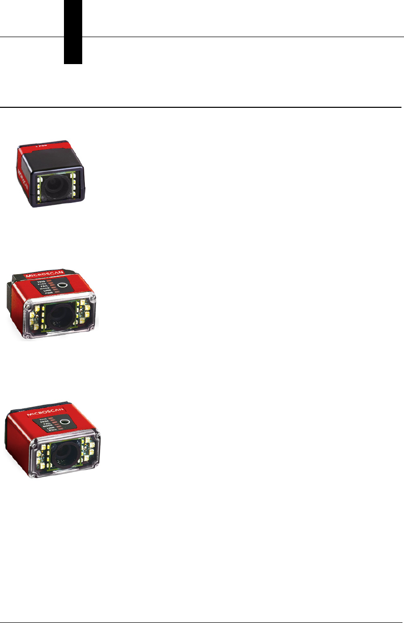
MV-20: OEM Smart Camera
The world’s smallest full-featured and fully-integrated smart
camera, the MicroHAWK MV-20 offers OEM integrators and
engineers a perfect set of value and performance options in a
tiny, simple, enclosed solution for embedded traceability and
inspection designs. The MV-20 offers a single-cable solution that
uses USB for both communication (USB 2.0 High Speed and
Ethernet over USB) and power to enable plug-and-play integration.
• IP40 • USB 2.0 High Speed • Ethernet over USB • 24 x 34 x 39 mm
MV-30: Miniature Serial / USB Smart Camera
A micro-sized smart camera with huge potential, the MV-30
furthers Microscan’s 30+-year legacy of innovative, space-efficient,
miniature design with a corner-exit cable and high-density 15-pin
connector (offering serial, USB 2.0 High Speed, and Ethernet
over USB capabilities) as well as optional liquid lens autofocus.
Perfect for OEMs and machine builders, the MV-30 offers the
perfect combination of size, performance, and flexible integration.
• IP54 • Serial RS-232 • USB 2.0 • Ethernet over USB • Autofocus • Corner-Exit Cable
MV–40: Industrial Ethernet Smart Camera
The MV-40 redefines the imaging market as the smallest
IP65/IP67-rated, true-industrial Ethernet smart camera. With the
library of Microscan's machine vision tools on board in a rugged,
ultra-compact case, the MV-40 is the complete package for
solving any vision inspection challenge under any condition.
Combining unprecedented ease of use, high-speed
communication, optional liquid lens autofocus, and ultra-small
form factor, the MV-40 is the ultimate compact machine vision
system in the industry.
• IP65 • EtherNet/IP • Ethernet TCP/IP • PROFINET • Autofocus • Power over Ethernet (PoE)
MicroHAWK MV-20, MV-30, and MV-40 Smart Camera Models
Introduction
1
MicroHAWK MV-20 / MV-30 / MV-40 Smart Camera Guide 1-5
Software Options
AutoVISION Software provides a simple setup and runtime interface for solving basic to
mid-range vision and auto ID challenges. Scalable with Visionscape Software.
Visionscape Software provides a professional setup and runtime interface with access to
Microscan’s full auto ID, verification, and machine vision tools.
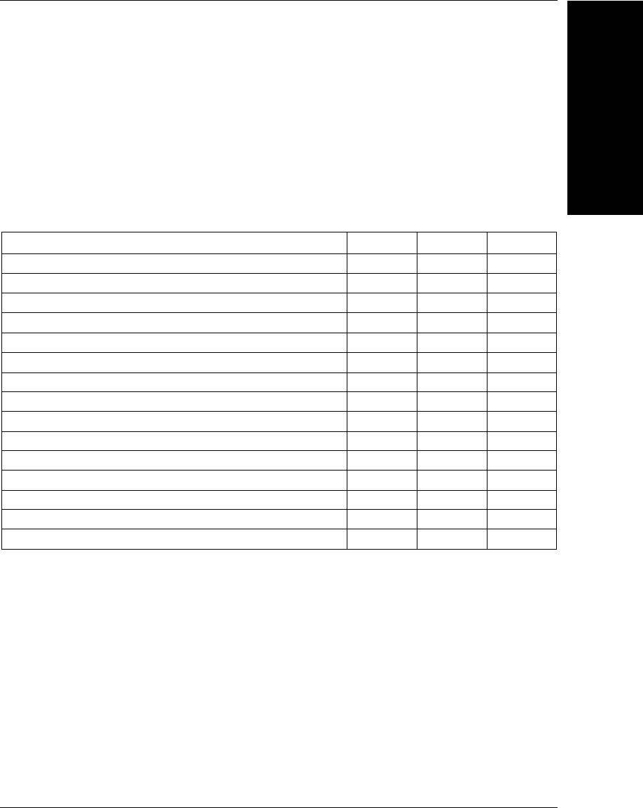
MicroHAWK Feature Comparison
Features MV-20 MV-30 MV-40
Barcode Reading (1D/2D) • • •
Complete Machine Vision • • •
Enclosure IP40 IP54 IP65/67
PROFINET •
Ethernet TCP/IP, EtherNet/IP •
Ethernet over USB • •
Serial (RS-232) • •
USB 2.0 High Speed / HID • •
Power over Ethernet (PoE) •
Outer Illumination • •
Liquid Lens Autofocus • •
Color Sensor •••
AutoVISION Sensor Software • • •
AutoVISION Software • • •
Visionscape Software • • •

Chapter 1Introduction
1-6 MicroHAWK MV-20 / MV-30 / MV-40 Smart Camera Guide
MicroHAWK MV Part Number Structure
MicroHAWK MV part numbers follow the format 7ABX-YZZZ-LPPP.
7 = MicroHAWK.
Example Part Number: 7422-3000-2004
Description: MicroHAWK MV-40, IP65 Case, 24V, Ethernet, Machine Vision, SXGA, 1.2 Megapixel,
Mono, Ultra-High Density, Autofocus, White Outer LEDs, AutoVISION + Verification + Visionscape.
(A) Model
1: Engine, No Case, USB
2: MV-20, IP40 Case, USB
3: MV-30, IP54 Case, 5V, USB
4: MV-40, IP65 Case, 24V, Ethernet
(B) Application Type
2: Machine Vision
(X) Sensor
1: WVGA 0.3 Megapixel, Mono
2: SXGA, 1.2 Megapixel, Mono
3: QSXGA, 5 Megapixel, Color
(Y) Optics
0: Custom
1: Standard Density – 5 mm Focal Length
2: High Density – 8 mm Focal Length
3: Ultra-High Density / Long Range – 16 mm Focal Length
(ZZZ) Focal Distance
000: Autofocus
050: 50 mm = 1.96 in.
102: 102 mm = 4.02 in.
190: 190 mm = 7.48 in.
300: 300 mm = 11.81 in.
(L) Illumination
0: Inner LEDs Only
1: Red Outer LEDs
2: White Outer LEDs
(PPP) Software
000: AutoVISION Sensor
001: AutoVISION
002: AutoVISION + Verification
003: AutoVISION + Visionscape
004: AutoVISION + Verification + Visionscape
Notes:
•(A) Model: The MicroHAWK Engine is available for OEM-certified partners only.
•
(L) Illumination:
Outer LEDs provide extra illumination. Base-level LED illumination included with all cameras.
•Field Upgrades: Not available for optics or illumination due to factory settings for optical alignment,
LED balancing, and sealing for IP enclosure rating. However, the camera’s software is field-upgradeable
via licenses.

MicroHAWK MV-20 / MV-30 / MV-40 Smart Camera Guide 2-1
2
System Components
2
CHAPTER 2 System Components
This section contains specific information about system components as
well as information to help you connect your MicroHAWK MV-20, MV-30,
or MV-40 Smart Camera.
Note: There are no user-serviceable parts inside the camera.

Chapter 2System Components
2-2 MicroHAWK MV-20 / MV-30 / MV-40 Smart Camera Guide
Hardware Components and Accessories
The table below lists MicroHAWK Smart Camera hardware components and the table on
the next page lists the accessories. The reference numbers shown on configuration drawings
later in this section refer to these tables.
Item Part Number Description
17ABX-YZZZ-LPPP MicroHAWK MV-20, MicroHAWK MV-30, or MicroHAWK MV-40
261-9000034-01 Cable, USB A to Micro B, 6 ft., MV-20
361-9000045-01 Cable, USB A to Micro B, 3 ft., MV-20
461-9000043-01 Cable, DB15 to BUS Power USB Type A, MV-30
598-9000048-01 Kit, Cable, DB15 to Ext. Power/RS-232 with Power Supply, MV-30 – includes
97-9000006-01 and 61-9000037-01
697-9000006-01 Power Supply, 5V – for use with cables 61-9000037-01 and 61-9000038-01
761-9000037-01 Cable, DB15 to Ext. Power/RS-232, MV-30
898-9000049-01 Kit, Cable, DB15 to Ext. Power/USB with Power Supply, MV-30 – includes
97-9000006-01 and 61-9000038-01
961-9000038-01 Cable, DB15 to Ext. Power/USB, MV-30
10 98-9000050-01 Kit, Cable, DB15 to Ext. Power/USB, I/O with Power Supply, MV-30 – includes
97-000011-02 and 61-9000039-01
11 97-000011-02 Power Supply, 100-240VAC, +5VDC, 2-Pin U.S./Euro Plug
12 61-9000039-01 Cable, DB15 to Ext. Power/USB, I/O, MV-30
13 97-000012-02 Power Supply, 100-240VAC, +24VDC, TRK 3-Pin, U.S./Euro Plug
14 99-000018-01 IB-131 Interface Box
15 FIS-0001-0035G Converter, IC-332, 24V/5V, Opto I/O – for use with IB-131
16 61-3000026-03 Cable, Communication, DB25 Plug to DB9 Socket, 6 ft.
17 99-000019-01 Photo Sensor, Visible, NPN, Light On, 5VDC
18 61-9000102-01 Cable, DB15 to USB/RS-232, Triggered, MV-30
19 97-000012-01 Power Supply, 100-240VAC, +24VDC, M12 12-Pin Socket
20 98-000103-02 QX-1 Interface Device
21 61-000162-02 Cordset, Common, M12 12-Pin Socket (Screw-On) to M12 12-Pin Plug
22 61-000160-03 Cordset, Host, Ethernet, M12 8-Pin Plug (Screw-On) to RJ45, 1 m.
23 99-000020-01 Photo Sensor, M12 4-Pin Plug, NPN, Dark Off, 2 m.
24 99-000020-02 Photo Sensor, M12 4-Pin Plug, NPN, Dark On, 2 m.
25 61-9000054-01 Cable, M12 12-Pin Socket to 9-Pin Socket and M12 Plug
26 61-9000088-01 Cable, M12 12-Pin Socket to USB Keyboard Wedge and M12 Plug
Upgrade to Visionscape
98-000217-01
Upgrade from AutoVISION to full Visionscape functionality
Mounting Options
98-9000034-01
MicroHAWK MV-20-to-MINI Hawk Adapter Plate Kit
Documentation
37-000010-01
Microscan Tools Drive (Software, documentation, links to Microscan website)

MicroHAWK MV Accessories
System Components
2
MicroHAWK MV-20 / MV-30 / MV-40 Smart Camera Guide 2-3
MicroHAWK MV-30 Connectivity Kits
98-9000048-01 Kit, Cable, DB15 to Ext. Power/RS-232 with Power Supply, MV-30 – includes 97-9000006-01
and 61-9000037-01
98-9000049-01 Kit, Cable, DB15 to Ext. Power/USB with Power Supply, MV-30 – includes 97-9000006-01
and 61-9000038-01
98-9000050-01
Kit, Cable, DB15 to Ext. Power/USB, I/O with Power Supply, MV-30 – includes 97-000011-02
and 61-9000039-01
Recommended items (not included with kit):
• 99-000019-01, Visible, NPN, Light On, 5VDC
• 61-000151-01, Flying Lead Cable
MicroHAWK Power Supplies
97-9000006-01 Power Supply, 5V – for use with cables 61-9000037-01 and 61-9000038-01
97-000011-02 Power Supply, 100-240VAC, +5VDC, 2-Pin U.S./Euro Plug
97-000012-01 Power Supply, 100-240VAC, +24VDC, TRK 3-Pin, U.S./Euro Plug
MicroHAWK Cables
61-9000034-01 Cable, USB A to Micro B, 6 ft., MV-20
61-9000045-01 Cable, USB A to Micro B, 3 ft., MV-20
61-9000037-01 Cable, DB15 to Ext. Power/RS-232, MV-30
61-9000038-01 Cable, DB15 to Ext. Power/USB, MV-30
61-9000039-01 Cable, DB15 to Ext. Power/USB, I/O, MV-30
61-9000043-01 Cable, DB15 to BUS Power USB, MV-30
61-9000102-01 Cable, DB15 to USB/RS-232 Triggered, MV-30
61-9000054-01 Cable, M12 12-Pin Socket to 9-Pin Socket and M12 Plug
61-9000088-01 Cable, M12 12-Pin Socket to USB Keyboard Wedge and M12 Plug
MicroHAWK Mounting Accessories
98-9000034-01 Kit, Adapter, MS-4 to MV-20
98-9000041-01 Kit, L-Bracket, MicroHAWK
98-9000047-01 Kit, 1/4-20 Camera Mount, MicroHAWK
98-9000052-01 Kit, Mounting Stand, Ram, MS-3, MS-4, MINI, MicroHAWK, 4"
98-9000053-01 Kit, Mounting Stand, Ram, MS-3, MS-4, MINI, MicroHAWK, 3"
98-9000054-01 Kit, Mounting, APG, MS-4, MINI, MicroHAWK
98-9000059-01 Kit, Adapter Plate, MS-4, MINI to MicroHAWK
Other Accessories
98-9000043-01 Kit, Diffuser, MicroHAWK MV-30/MV-40
98-9000044-01 Kit, Polarizer, MicroHAWK MV-30/MV-40
98-9000045-01 Kit, Red LED, MicroHAWK MV-30/MV-40
98-9000046-02 Kit, White LED, MicroHAWK MV-30/MV-40
98-9000051-01 Kit, Window, MicroHAWK MV-30/MV-40
98-9000057-01 Kit, Right-Angle Mirror, MicroHAWK MV-20
98-9000058-01 Kit, Right-Angle Mirror, MicroHAWK MV-30/MV-40
98-9000064-01 Kit, Isolation Mounting, M3, MicroHAWK MV-30/MV-40
Chapter 2System Components
2-4 MicroHAWK MV-20 / MV-30 / MV-40 Smart Camera Guide
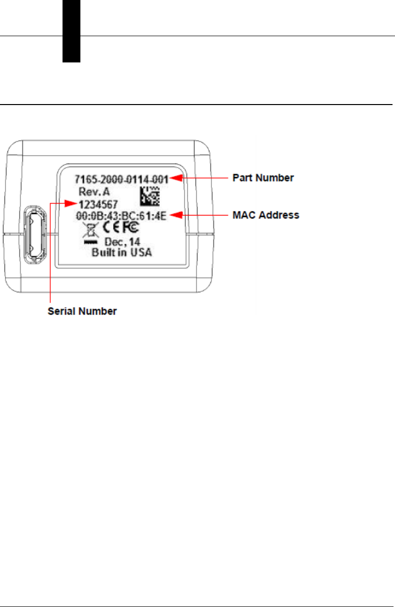
Label Information
Each MicroHAWK MV-20 / MV-30 / MV-40 Smart Camera has a label that contains important
information about that camera.
•Part Number – The Microscan part number of your MicroHAWK Smart Camera.
•Serial Number – The serial number of your MicroHAWK Smart Camera.
•MAC Address – The MAC address of your MicroHAWK Smart Camera.
Mechanical Dimensions
System Components
2
MicroHAWK MV-20 / MV-30 / MV-40 Smart Camera Guide 2-5
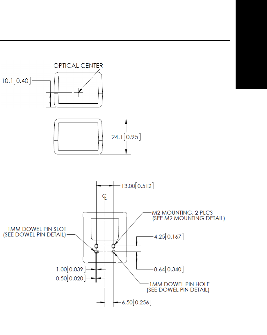
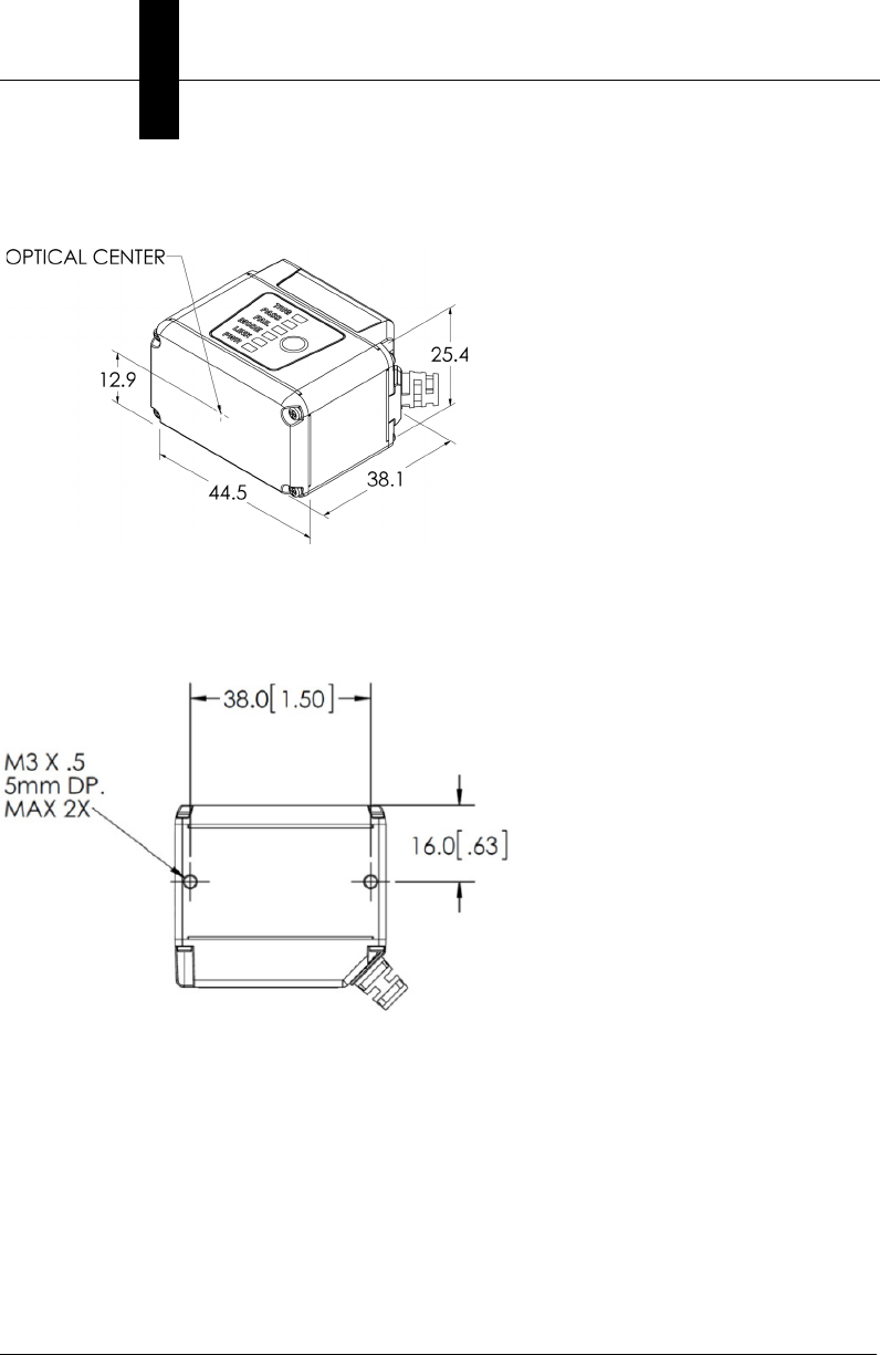
Mechanical Dimensions
MV-20 Front
MV-20 Base
Chapter 2System Components
2-6 MicroHAWK MV-20 / MV-30 / MV-40 Smart Camera Guide
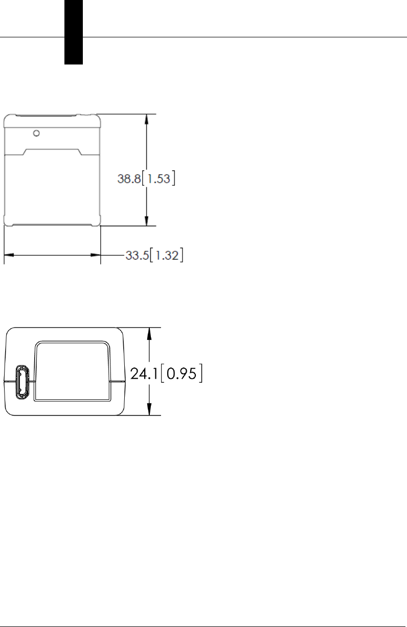
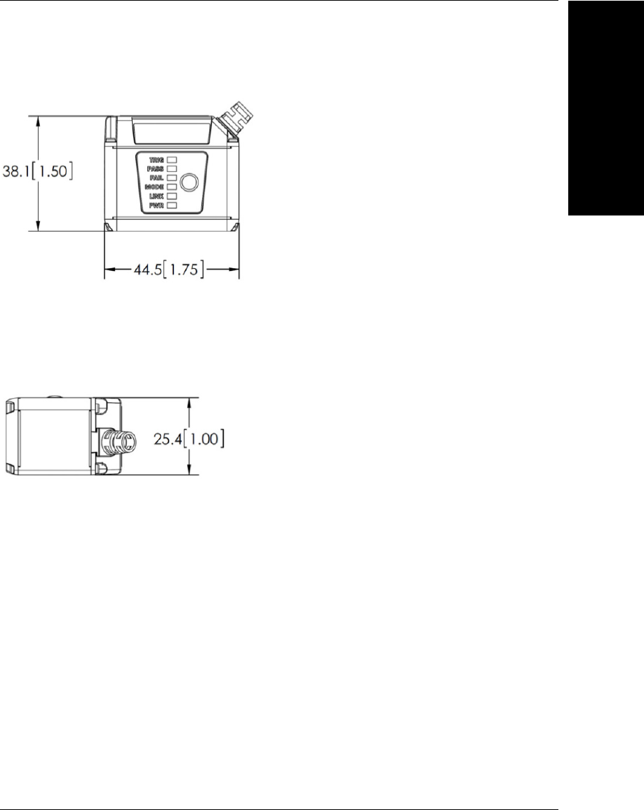
MV-20 Top
MV-20 Back
Mechanical Dimensions
System Components
2
MicroHAWK MV-20 / MV-30 / MV-40 Smart Camera Guide 2-7
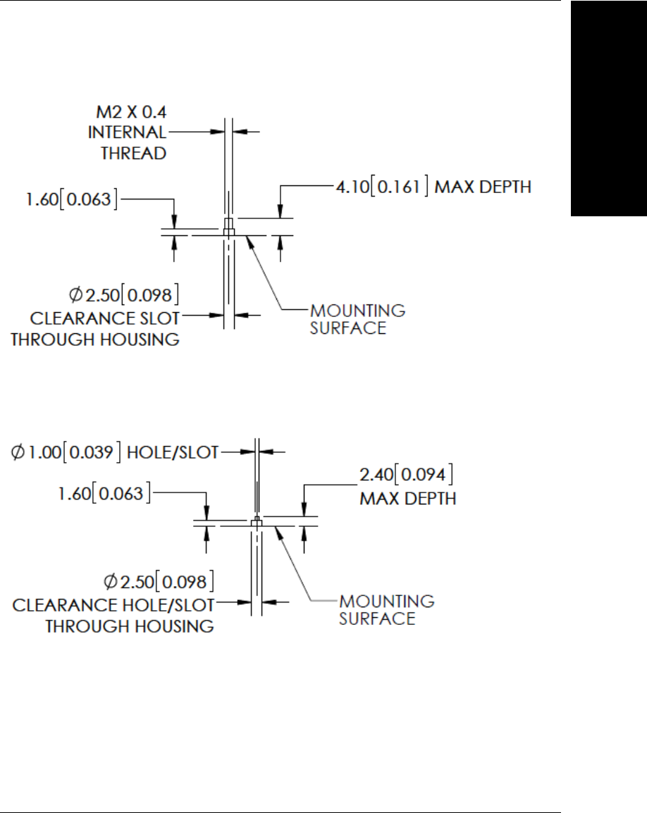
MV-20 M2 Mounting Detail
MV-20 Dowel Pin Detail
Chapter 2System Components
2-8 MicroHAWK MV-20 / MV-30 / MV-40 Smart Camera Guide
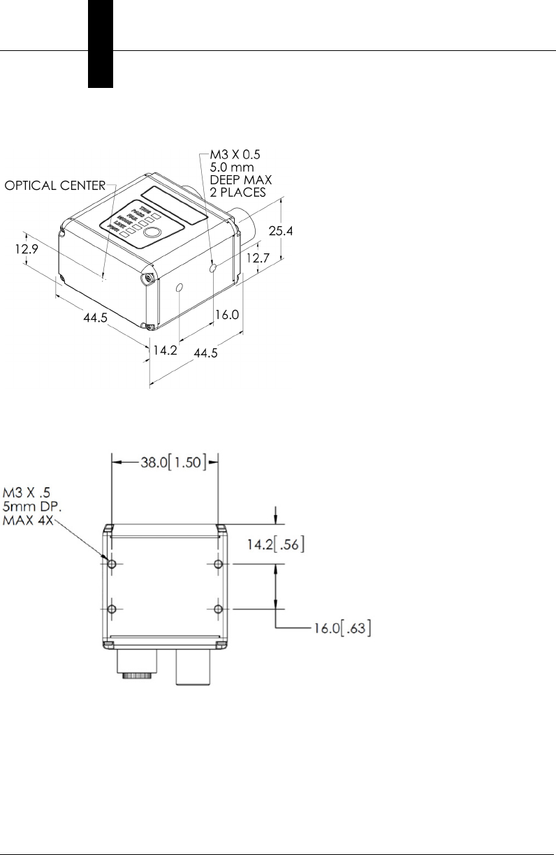
MV-30 Front
MV-30 Base
Mechanical Dimensions
System Components
2
MicroHAWK MV-20 / MV-30 / MV-40 Smart Camera Guide 2-9
MV-30 Top
MV-30 Side
Chapter 2System Components
2-10 MicroHAWK MV-20 / MV-30 / MV-40 Smart Camera Guide
MV-40 Front
MV-40 Base

Mechanical Dimensions
System Components
2
MicroHAWK MV-20 / MV-30 / MV-40 Smart Camera Guide 2-11
MV-40 Top
MV-40 Side
Chapter 2System Components
2-12 MicroHAWK MV-20 / MV-30 / MV-40 Smart Camera Guide
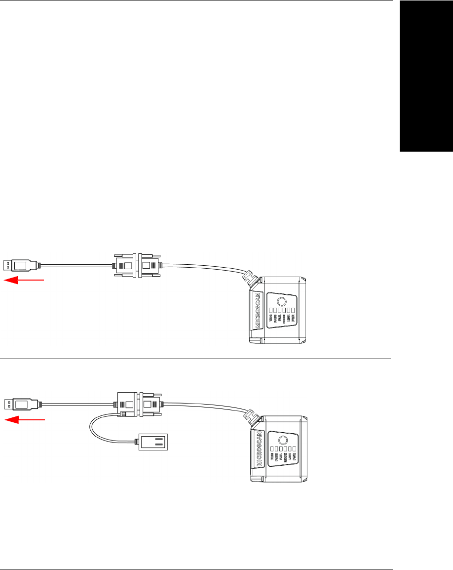
Cabling Configurations
MV-20
Note:
The numbers in the diagram correspond to the numbers in the
Hardware Components
and Accessories
table.
• Mount the camera securely in its camera stand (not supplied).
• Mount the camera (as required by the application.
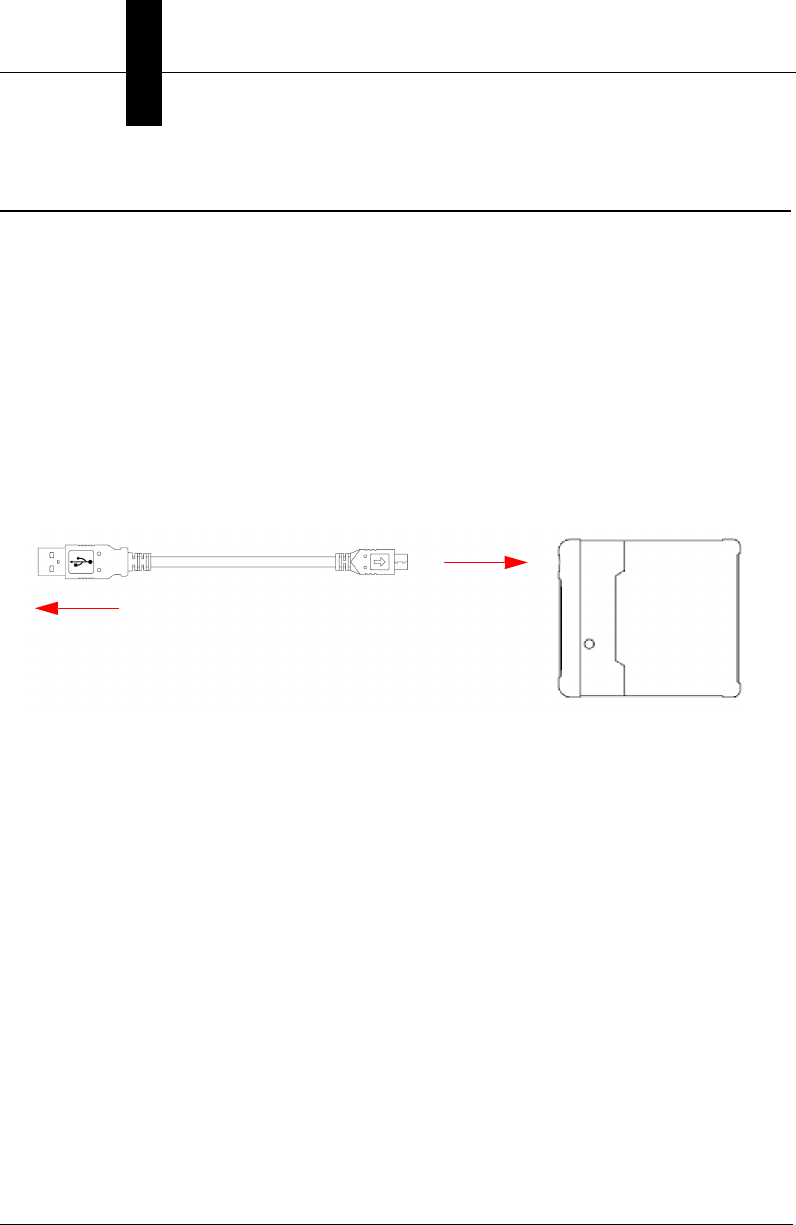
• Connect the Micro-USB Type B side of the USB cable to the MicroHAWK MV-20.
•
Connect the USB Type A side of the USB cable to the host
.
MV-20 Power Requirements
The MicroHAWK MV-20 Smart Camera is a USB 2.0 bus-powered device. The camera
is a high-powered device, and the host must be capable of supplying up to five unit loads
(500 mA).
To Host
USB Type A Plug Micro-USB
Type B Plug
1
2
Cabling Configurations
System Components
2
MicroHAWK MV-20 / MV-30 / MV-40 Smart Camera Guide 2-13
MV-30
Note:
The numbers in the diagram correspond to the numbers in the
Hardware Components
and Accessories
table.
• Mount the camera securely in its camera stand (not supplied).
• Mount the camera as required by the application.
• Connect the integrated corner-exit cable to the MicroHAWK MV-30.
• Connect the accessory USB cable to the integrated corner-exit cable.
•
Connect the USB Type A side of the USB cable to the host
.
• Connect the power cable into the power source.
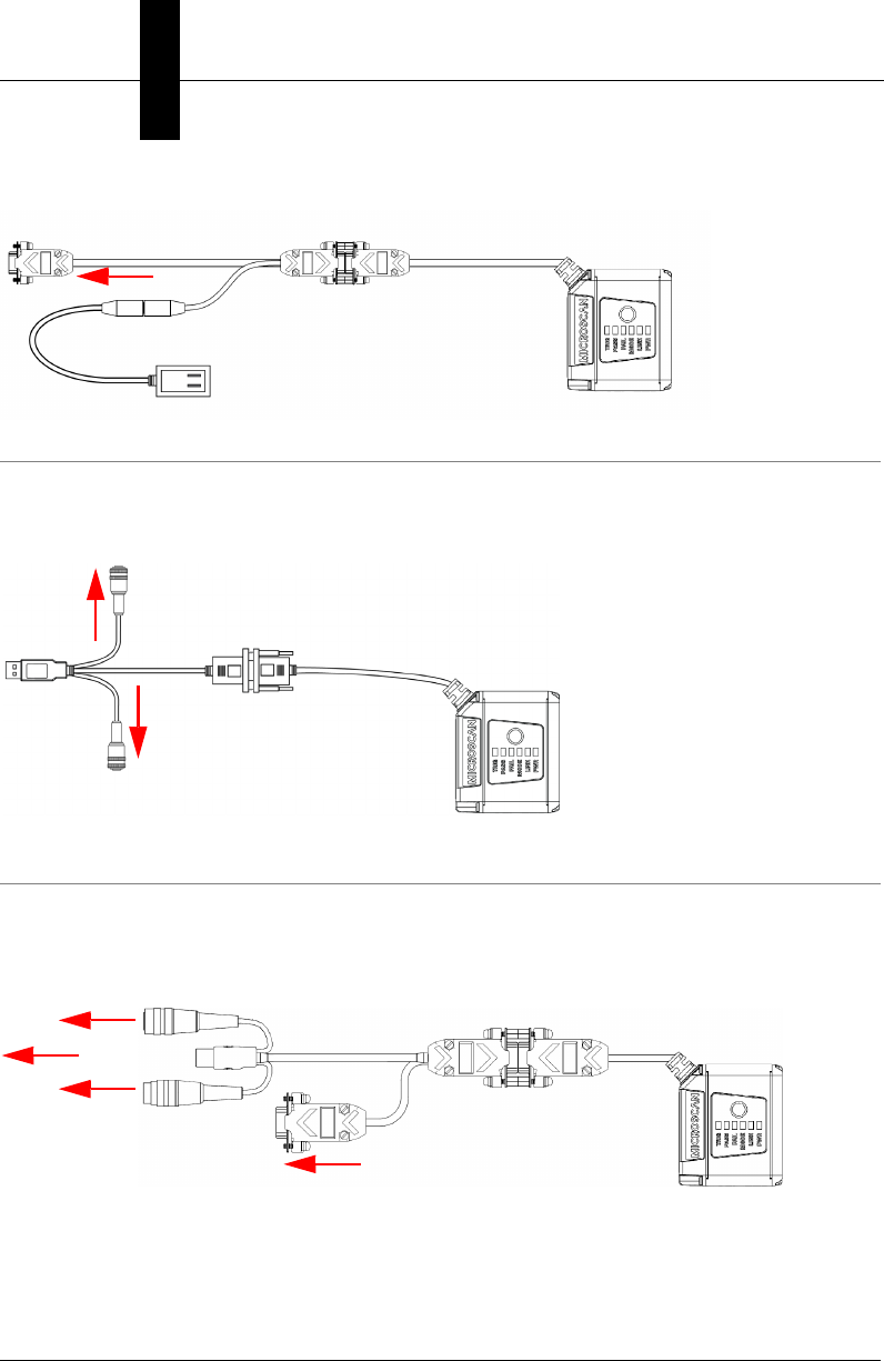
MicroHAWK MV-30 with DB15 to BUS Power USB Type A
MicroHAWK MV-30 with DB15 to Ext. Power/USB Type A
1
Integrated
Corner-Exit
Cable
Accessory USB
Cable to Host
4
To Host
To Host
Integrated
Corner-Exit
Cable
1
Accessory USB
Cable to Host
Power Supply
6
9
Note: BUS-powered cable delivers reduced illumination –
approximately 30% less brightness.
Chapter 2System Components
2-14 MicroHAWK MV-20 / MV-30 / MV-40 Smart Camera Guide
MicroHAWK MV-30 with DB15 to Ext. Power/RS-232
MicroHAWK MV-30 with DB15 to Ext. Power/USB, I/O
1
1
Power
Supply
To host Integrated
Corner-Exit
Cable
6
7
To Trigger
Accessory
USB Cable
to Host
Integrated
Corner-Exit
Cable
To
Power
Supply
12
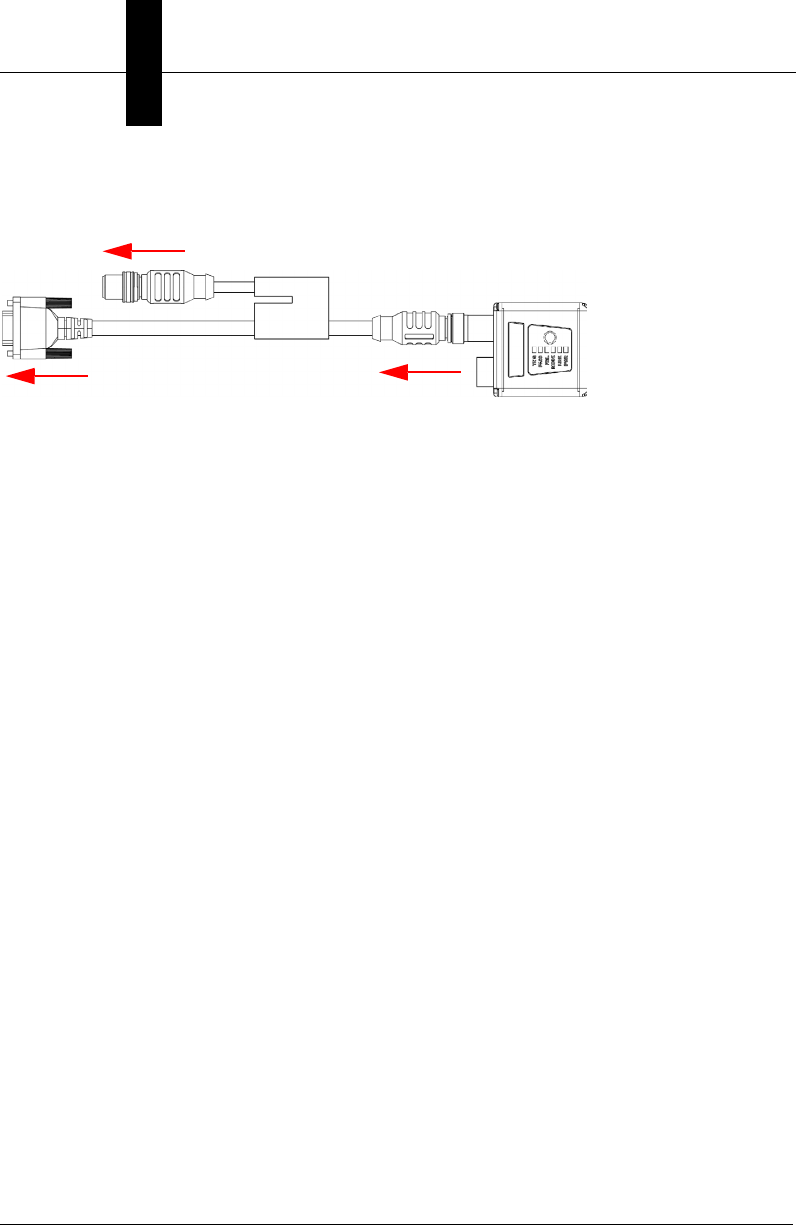
MicroHAWK MV-30 with DB15 to USB/RS-232, Triggered
1
18
To Host
To Trigger
To Power Supply
To Host
(RS-232)
Integrated
Corner-Exit
Cable
Accessory
USB Cable
to Host
Cabling Configurations
System Components
2
MicroHAWK MV-20 / MV-30 / MV-40 Smart Camera Guide 2-15
MV-30 Power Requirements
The MicroHAWK MV-30 Smart Camera is an RS-232 or USB 2.0 bus-powered device.
The camera is a high-powered device, and the host must be capable of supplying up to
five unit loads (600 mA).
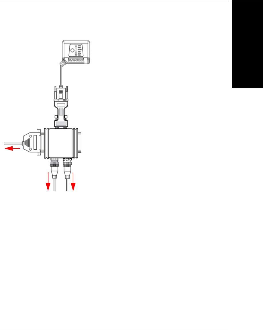
MicroHAWK MV-30 with IB-131 and IC-332
To
power
supply
IC-332
To external
trigger
1
15
16 14
13 17
To
Host
Chapter 2System Components
2-16 MicroHAWK MV-20 / MV-30 / MV-40 Smart Camera Guide
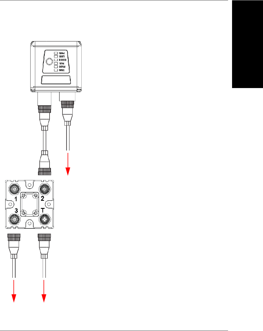
MV-40
Note:
The numbers in the diagram correspond to the numbers in the
Hardware Components
and Accessories
table.
• Mount the camera securely in its camera stand (not supplied).
• Mount the camera as required by the application.
• Connect the power cable to the MicroHAWK MV-40.
• Connect the Ethernet cable to the MicroHAWK MV-40.
• Connect the Ethernet cable to the host.
• Connect the power cable into the power source.
1
19
22
To Power
Supply
(12-Pin Plug)
To Host
(Ethernet
8-Pin Plug
to RJ45)
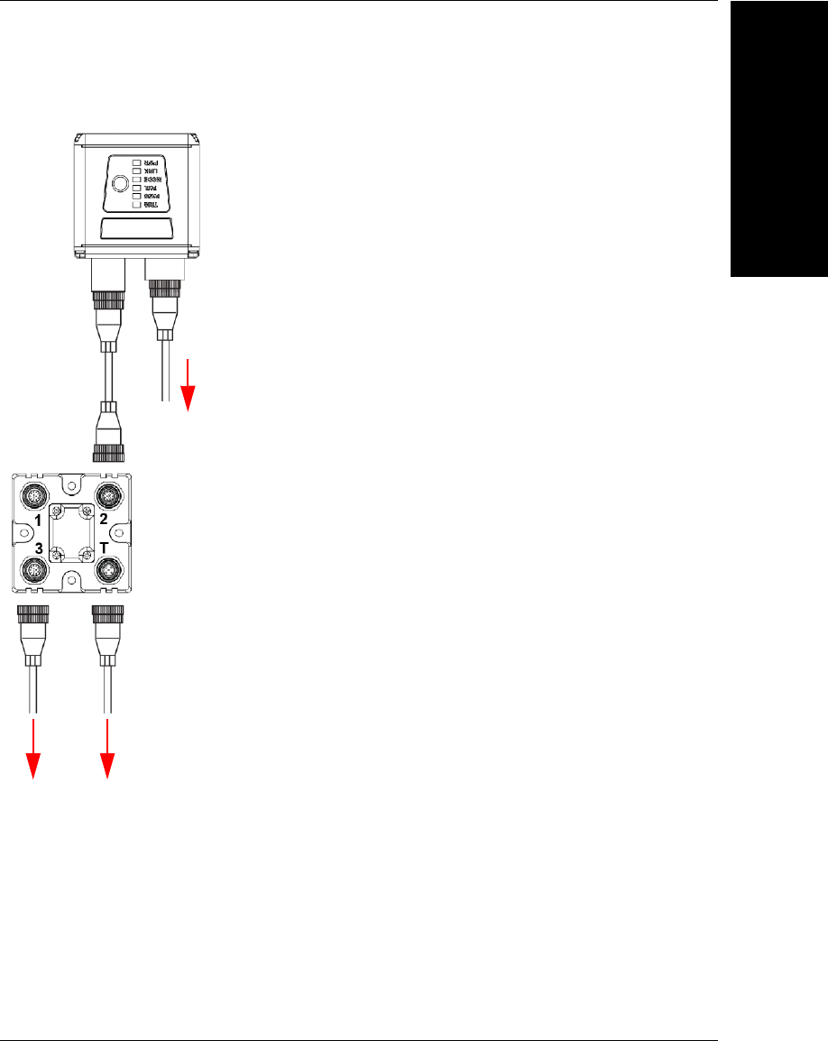
MicroHAWK MV-40 Simple Configuration
Cabling Configurations
System Components
2
MicroHAWK MV-20 / MV-30 / MV-40 Smart Camera Guide 2-17
1
21 22
20
19 22 or 23
Common
(12-Pin Plug
to 12-Pin
Socket) To Host
(Ethernet
8-Pin Plug
to RJ45)
To Trigger
To Power
Supply
MicroHAWK MV-40 with QX-1 Interface Device
Chapter 2System Components
2-18 MicroHAWK MV-20 / MV-30 / MV-40 Smart Camera Guide
MV-40 Power Requirements
The MicroHAWK MV-40 Smart Camera is an RS-232-powered device. The camera is a
high-powered device, and the host must be capable of supplying up to twenty-four unit
loads (150mA).
MicroHAWK MV-40 M12 12-Pin Socket to 9-Pin Socket and M12 Plug
1
25
To Power Supply (19) or: Flying Lead Cable
(61-000167-02); QX-1; MS-Connect 210.
To Host
(RS-232)
To Ethernet
Mounting the Camera
System Components
2
MicroHAWK MV-20 / MV-30 / MV-40 Smart Camera Guide 2-19
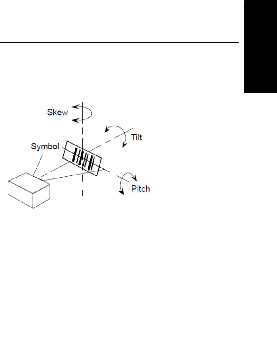
Mounting the Camera
Mount and Position the Camera
1. Position the camera at a focal distance of one inch or more from a test object.
2. Tip the camera relative to the object to avoid the glare of direct (specular) reflection.
The case parting line should be perpendicular to the plane of the symbol by either
pitching the symbol or the camera. Avoid excessive skew or pitch. Maximum skew is
±30°; maximum pitch is ±30°.
Chapter 2System Components
2-20 MicroHAWK MV-20 / MV-30 / MV-40 Smart Camera Guide
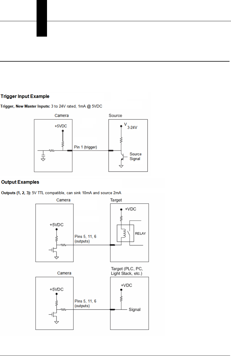
I/O Wiring
MicroHAWK MV-30
Direct Input / Output Diagrams (MV-30)
I/O Wiring
System Components
2
MicroHAWK MV-20 / MV-30 / MV-40 Smart Camera Guide 2-21
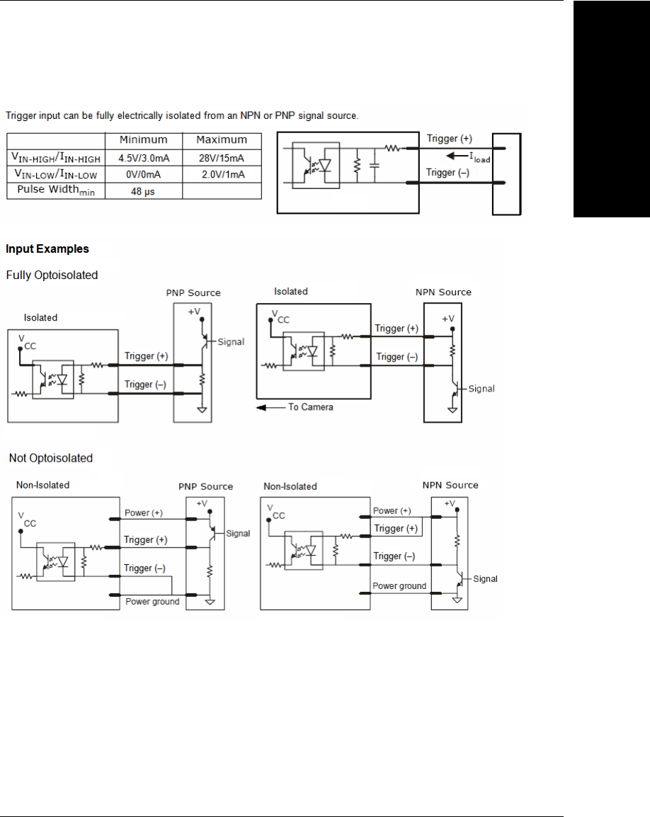
Optoisolator Trigger Inputs for IC-332 (MV-30)
Chapter 2System Components
2-22 MicroHAWK MV-20 / MV-30 / MV-40 Smart Camera Guide
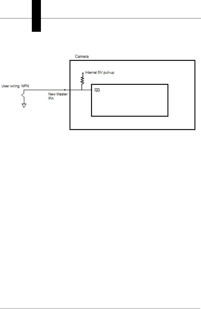
New Master Pin (MV-30)
I/O Wiring
System Components
2
MicroHAWK MV-20 / MV-30 / MV-40 Smart Camera Guide 2-23
MicroHAWK MV-40
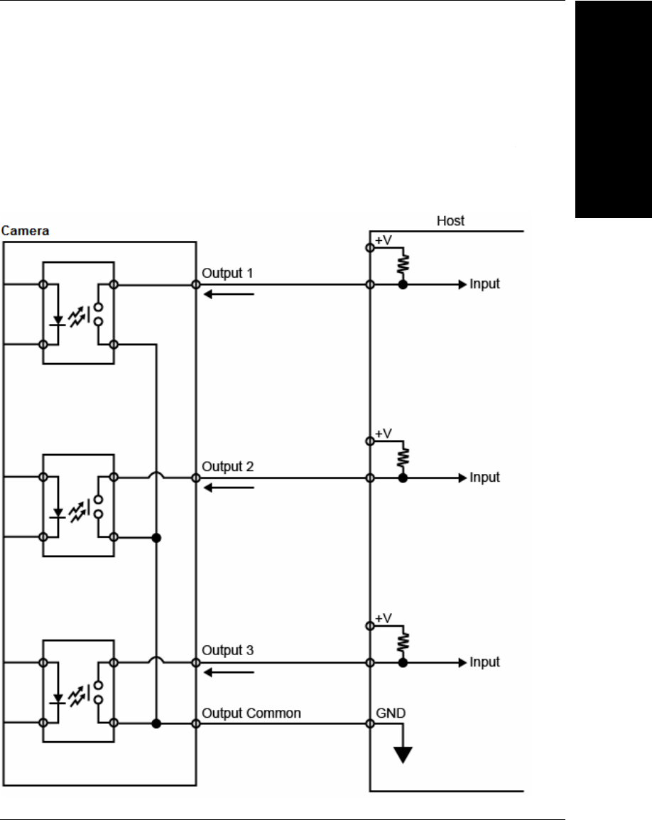
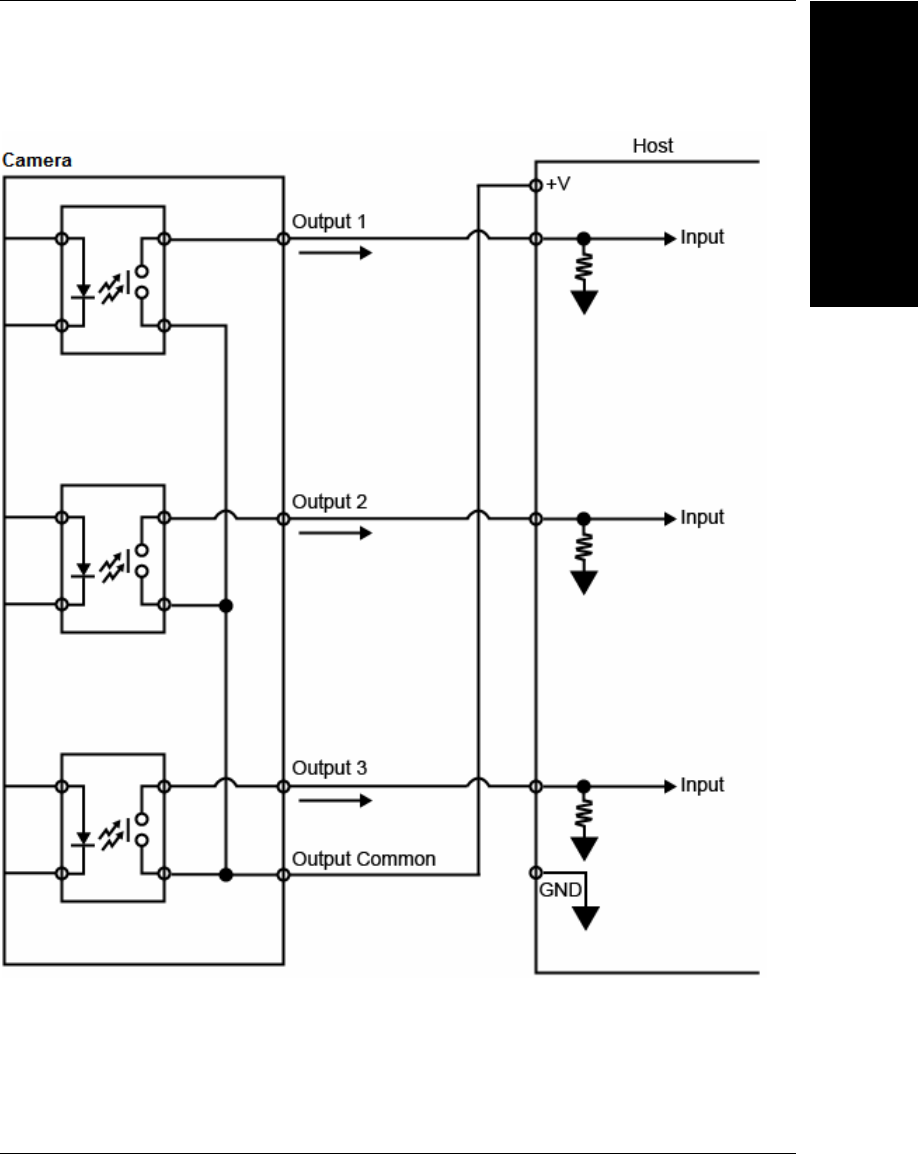
Optoisolated Outputs (MV-40)
The camera has optoisolated outputs that can transfer signals from the camera to
peripherals. Outputs can be configured as either NPN or PNP, but NPN and PNP cannot
be mixed in a system, because the output common is shared by all outputs.
NPN Output for Host Input (MV-40)
Chapter 2System Components
2-24 MicroHAWK MV-20 / MV-30 / MV-40 Smart Camera Guide
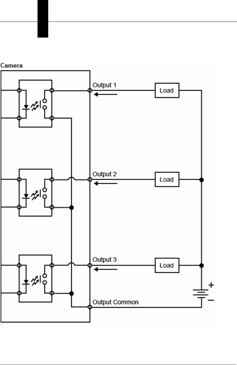
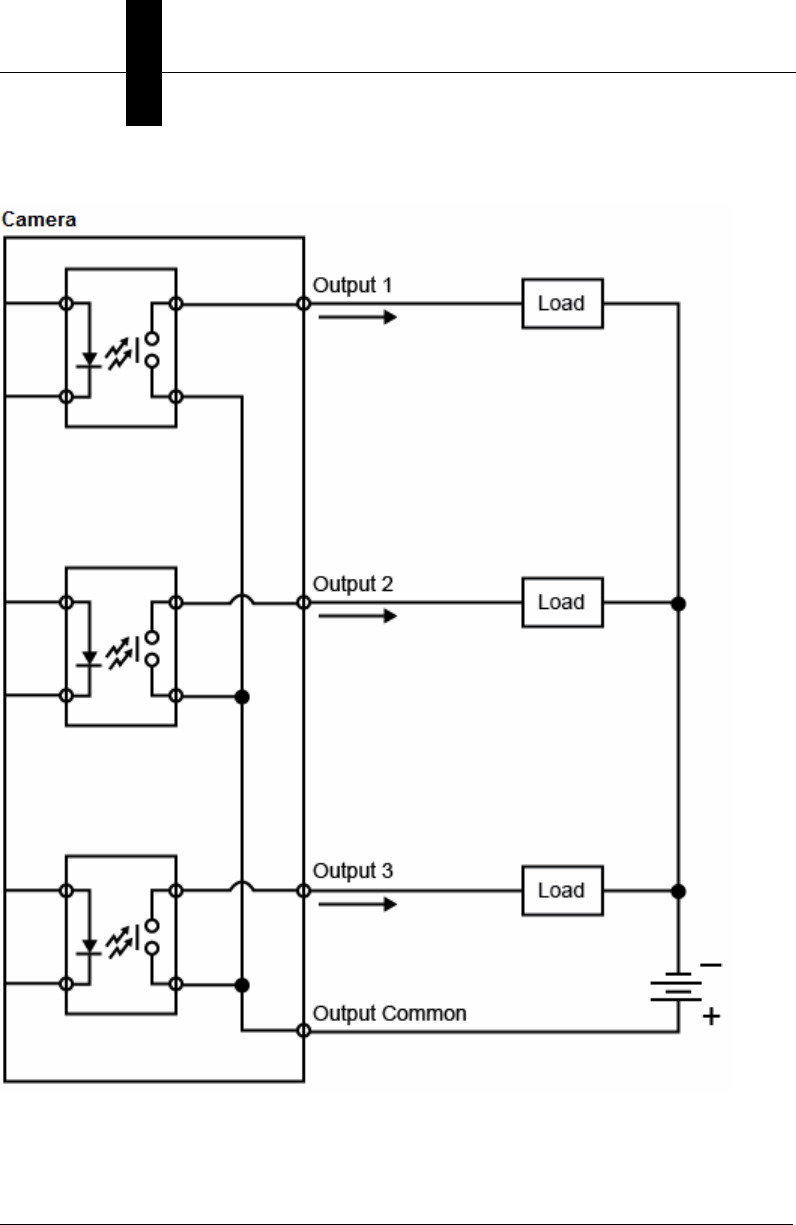
NPN Output for External Load (MV-40)
I/O Wiring
System Components
2
MicroHAWK MV-20 / MV-30 / MV-40 Smart Camera Guide 2-25
PNP Output for Host Input (MV-40)
Chapter 2System Components
2-26 MicroHAWK MV-20 / MV-30 / MV-40 Smart Camera Guide
PNP Output for External Load (MV-40)
I/O Wiring
System Components
2
MicroHAWK MV-20 / MV-30 / MV-40 Smart Camera Guide 2-27
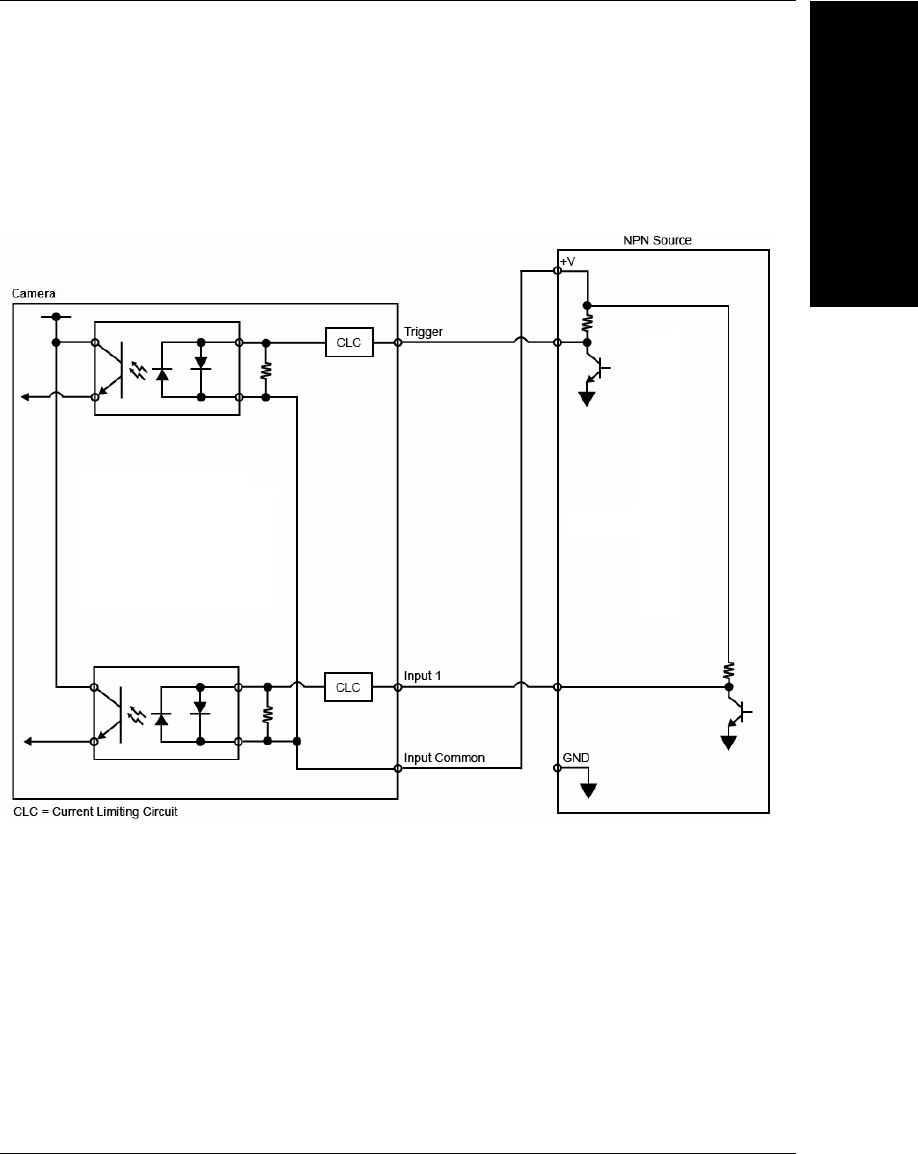
Optoisolated Inputs (MV-40)
All discrete inputs are optoisolated. Inputs can be configured as either NPN or PNP, but NPN
and PNP cannot be mixed in a system, because the input common is shared by all inputs.
NPN (MV-40)
Chapter 2System Components
2-28 MicroHAWK MV-20 / MV-30 / MV-40 Smart Camera Guide
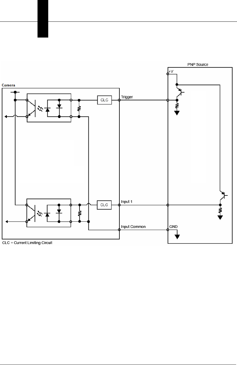
PNP (MV-40)
I/O Wiring
System Components
2
MicroHAWK MV-20 / MV-30 / MV-40 Smart Camera Guide 2-29
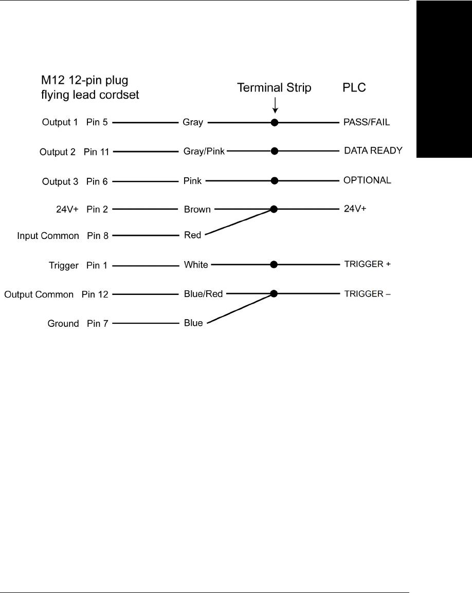
Example Wiring (MV-40) for PLC Communications, NPN Outputs, NPN Inputs
Chapter 2System Components
2-30 MicroHAWK MV-20 / MV-30 / MV-40 Smart Camera Guide
Grounding and Power
Ground and Shield Considerations
Proper grounding is necessary for operator safety, noise reduction, and the protection of
equipment from voltage transients. Buildings, including any steelwork, all circuits, and all
junction boxes must be grounded directly to an earth ground in compliance with local and
national electrical codes.
Ground Loops
Ground loops (signal degradation due to different ground potentials in communicating
devices) can be eliminated or minimized by ensuring that both the host, imager, and their
power supplies are connected to a common earth ground.
An earth ground is provided through the cable shields and chassis of the camera.
MicroHAWK
MV-40
Grounding and Power
System Components
2
MicroHAWK MV-20 / MV-30 / MV-40 Smart Camera Guide 2-31
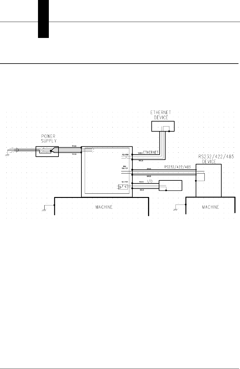
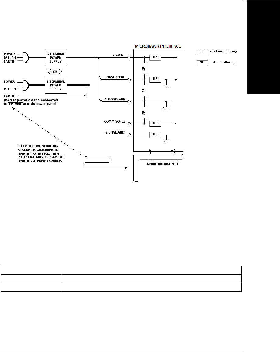
Expected Power and Ground Connections for Proper Operation
Grounding Notes
• Ensure that mounting bracket “Earth” is at the same potential as power source “Earth”.
• Supply “Return” and “Earth” ground must be stable, low-impedance reference points.
• “2-Terminal Power Supply” must still provide an “Earth” connection to the imager.
• “Signal Ground” can be used for communications and/or discrete signal ground
reference. It must not be used as Power Ground or Earth Ground.
MicroHAWK Power Requirements
Refer to this table when determining the power requirements for your camera.
MicroHAWK MV-20 5VDC ± 5%; 350mA at 5VDC (typ.)
MicroHAWK MV-30 5V ± 5%; 600mA at 5VDC (typ.)
MicroHAWK MV-40 4.75V – 30V; 150mA at 24VDC (typ.)

Chapter 2System Components
2-32 MicroHAWK MV-20 / MV-30 / MV-40 Smart Camera Guide
I/O Filtering and Debounce
Trigger Debounce
is the ability of the system to accommodate switching noise on a trigger state
change – a common issue with relays that have some intermittent contact while engaging.
Trigger overruns (when the vision system is triggered faster than the device can process)
can be avoided by increasing the “debounce” time in the camera definition file located in
the C:\Microscan\Vscape\Drivers\CamDefs directory.
The I/O Line Debounce High Time and IO Line Debounce Low Time can be added to the
file as in the example below. Debounce time is 1 ms (1,000 μs).
Note: Although the value entered for the "IO Line Debounce Time" is in microseconds, it
will only be rounded up to a millisecond value. For example, entering the value 1001 will
resolve to 2 ms; entering a value of 2800 will resolve to 3 ms.
The min value for "IO Line Debounce Time" is 0, which disables software debounce
altogether. The maximum value is 100000 (100 ms).
We have the standard debounce as described for the trigger:
IO Line Debounce High Time 1000 //usecs (default is 0)
IO Line Debounce Low Time 1000 //usecs (default is 0)
The MicroHAWK has an I/O Line Filter Time as well:
IO Line Filter High Time 100 //usecs (default is 100)
IO Line Filter Low Time 100 //usecs (default is 100)
I/O Filter is the ability to ignore any signals on the l/O lines that are less that the “Filter Time”
long. Sometimes, electrical interference puts spikes on the line. This feature makes it ignore
them until the signal that is seen on the I/O line is longer than the filter time.

Camera Definition File Example
System Components
2
MicroHAWK MV-20 / MV-30 / MV-40 Smart Camera Guide 2-33
Camera Definition File Example
// Camera Definition File
// Version: 1.04
Camera Name MicroHAWK 1280x960 // Name Displayed in
Camdef Selection Dialog
Digitizer Type 6001 // Number
associated with Trident SXGA
Stride 1280 // Image Width
Rows 960 // Image Height
X Offset 0 // Image X Offset
Y Offset 0 // Image Y Offset
Bits Per Pixel 8 // Bits that represent Pixel Value
Pixel Type 0 // Type of Pixel:
MONOCHROME=0, COLOR_RGB=1, COLOR_BGR=2, COLOR_BAYGR8=3, COLOR_BAYRG8=4,
COLOR_BAYGB8=5, COLOR_BAYBG8=6, COLOR_HSI=7
Image Structure 1 // Pixel Organization: Packed=1, TwoPlanes =
2, ThreePlanes = 3
Async Control 1 // Controllable shutter time. Usually
using a pulse width specified in usecs
Usecs Per Frame 18518 // Fastest time to acquire a frame: 54 FPS
// -1 Disables
timeout feature
Binning 0
Zoomed 0
// IO Configuration
GPIO Edit Mask 0x0000
GPIO Defaults 0x0001 // 1 General Purpose Input 3 General Purpose
Outputs
GPIO Count 4
GPIO Inputs 1
GPIO Outputs 3
Sensors 1 // One input dedicated
to Trigger signal
Strobes 0
Virtual IO 2048
IO Line Filter High Time 100 //usecs (default is 100)
IO Line Filter Low Time 100 //usecs (default is
100)
IO Line Debounce High Time 0 //usecs (default is 0)
IO Line Debounce Low Time 0 //usecs (default is 0)
Sensor Trigger Delay Time 0 //usecs
Custom External Strobe Delay Time0 //usecs
// Focus & Photometry Ranges
Gain Dflt 20
Gain Min 0
Gain Max 100 // 0 to 100%
Exp Dflt 4000
Exp Min 66
Exp Max 58825 // 1/17 to 1/15,000
Focus Dflt 100 // 100 mm default
Focus Min 50
Focus Max 500 // 50 to 500 mm
Chapter 2System Components
2-34 MicroHAWK MV-20 / MV-30 / MV-40 Smart Camera Guide
Status Indicators
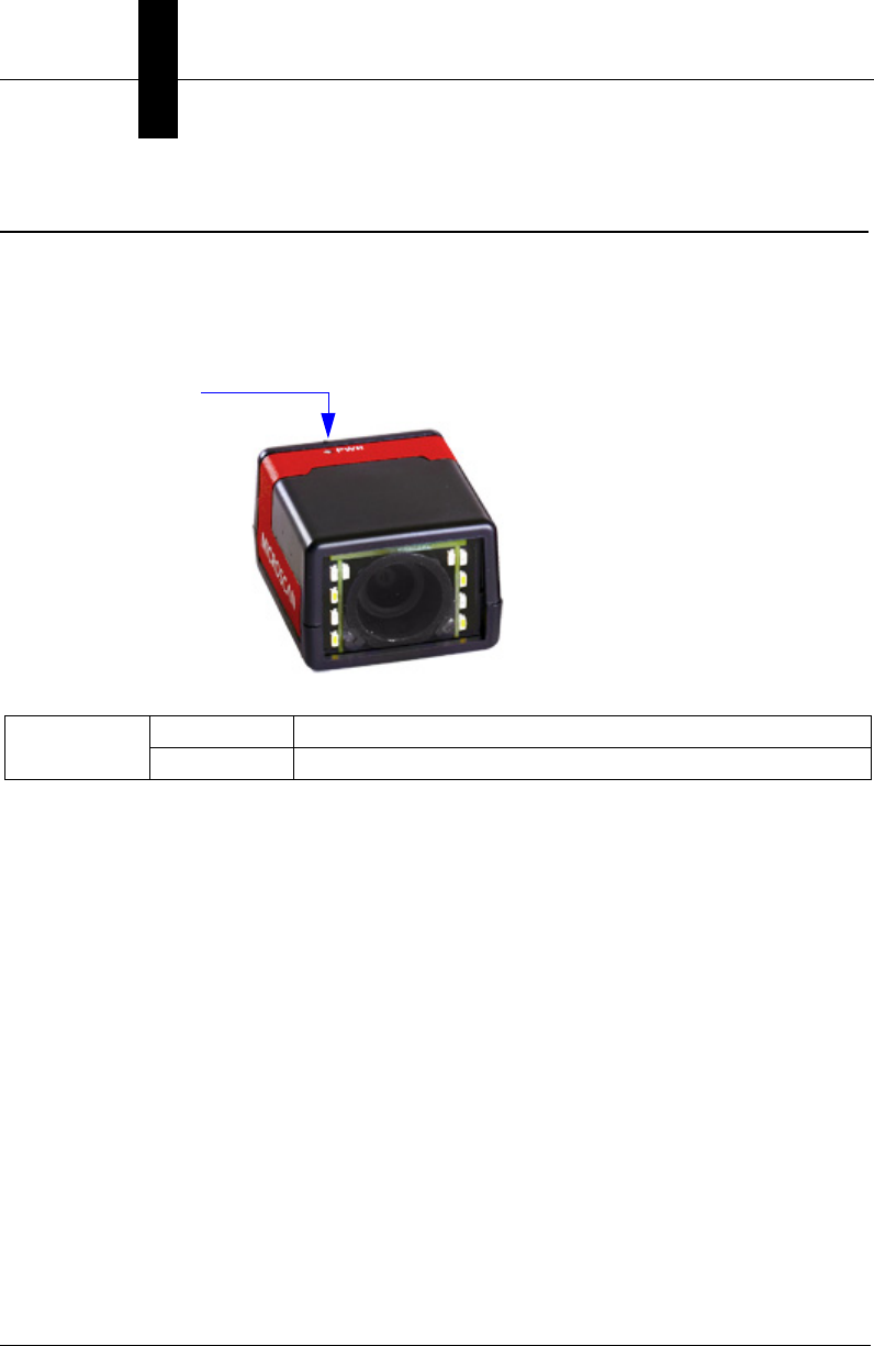
MV-20
The top of the MicroHAWK MV-20 Smart Camera has an LED that indicates whether or not
the device is powered-on.
Additional User Feedback
• Green Flash – A green flash from the front of the unit indicates a Good Read.
• Blue Targeting Pattern – The blue targeting pattern from the front of the unit allows the
user to center an object in the camera’s field of view.
PWR LED On Power On
Off No Power Applied to Unit
Power Indicator LED
Status Indicators
System Components
2
MicroHAWK MV-20 / MV-30 / MV-40 Smart Camera Guide 2-35
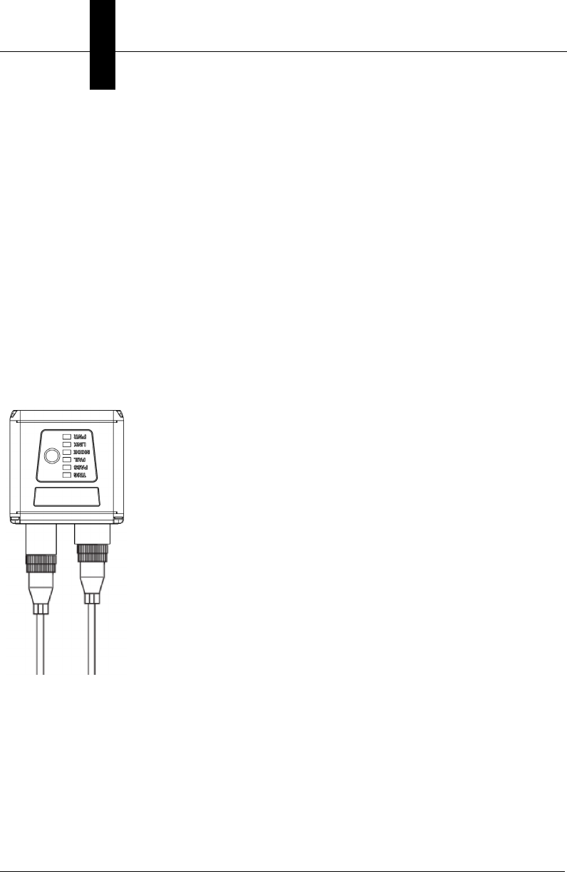
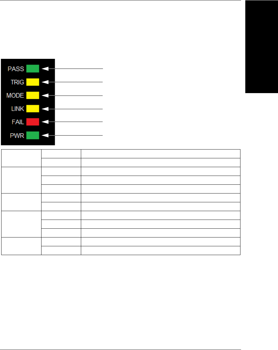
MV-30, MV-40 Status Indicators
The top of the MicroHAWK MV-30 and MV-40 Smart Cameras have multiple LEDs that
indicate different inspection, trigger, camera, communication, and power states.
Additional User Feedback
•Green Flash – A green flash from the front of the unit indicates a Good Read.
•Blue Targeting Pattern – The blue targeting pattern from the front of the unit allows
the user to center an object in the camera’s field of view.
PASS/FAIL On Active State
Off Inactive State
TRIG
On Steady Continuous Trigger
Off Waiting for Trigger Event
On Flashing Trigger Event
MODE On Steady Unit Ready
Off Unit Not Ready
LINK
On Steady Link Established
Off No Link/Activity
On Flashing Link Established and Activity on Link
PWR On Power On
Off No Power Applied to Unit
Trigger Status
Inspection Status
Camera Status
Communication Status
Power Status
Inspection Status

Chapter 2System Components
2-36 MicroHAWK MV-20 / MV-30 / MV-40 Smart Camera Guide

MicroHAWK MV-20 / MV-30 / MV-40 Smart Camera Guide 3-1
3
Getting Started with
AutoVISION
3
CHAPTER 3 Getting Started with
AutoVISION
This section describes how to set up and use MicroHAWK MV-20, MV-30,
and MV-40 Smart Cameras with AutoVISION Software.
3

Chapter 3Getting Started with AutoVISION
3-2 MicroHAWK MV-20 / MV-30 / MV-40 Smart Camera Guide
Setting Up a Job in AutoVISION
AutoVISION is a critical component of the MicroHAWK’s functionality. Designed for use
with the MicroHAWK, AutoVISION provides an intuitive interface, step-by-step
configuration, and a library of presets that allow easy setup and deployment. For more
complex vision applications, the system can be upgraded from AutoVISION to
Visionscape.
1. Configure MicroHAWK Hardware
• Mount the camera as required by the application.
• Connect the Ethernet cable from "B" on the camera to the network.
• Connect the power supply to "3" on the QX-1.
• Connect the photo sensor to "T" on the QX-1.
• Connect the "Common" cable to "2" on the QX-1 and "A" on the camera.
• Plug in the power supply.
Item Part Number Description
17ABX-YZZZ-LPPP MicroHAWK MV-20, MicroHAWK MV-30, or MicroHAWK MV-40
297-000012-01 Power Supply, 100-240VAC, +24VDC, M12 12-Pin Socket
398-000103-02 QX-1 Interface Device
461-000162-02 Cordset, Common, M12 12-Pin Socket (Screw-On) to M12 12-Pin Plug
561-000160-03 Cordset, Host, Ethernet, M12 8-Pin Plug (Screw-On) to RJ45, 1 m.
699-000020-01 Photo Sensor, M12 4-Pin Plug, NPN, Dark Off, 2 m.
Note: Additional cables available in the Microscan Product Pricing Catalog.
Setting Up a Job in AutoVISION
Getting Started with
AutoVISION
3
MicroHAWK MV-20 / MV-30 / MV-40 Smart Camera Guide 3-3
1
4
5
3
25 or 6
Common
(12-Pin
Plug to
12-Pin
Socket)
To Host
(Ethernet
8-Pin Plug
to RJ45)
To
Trigger
To
Power
Supply
MicroHAWK MV-40 with QX-1 Interface Device
See Appendix A, Connector Pinouts,
for MicroHAWK pin assignments.
Chapter 3Getting Started with AutoVISION
3-4 MicroHAWK MV-20 / MV-30 / MV-40 Smart Camera Guide
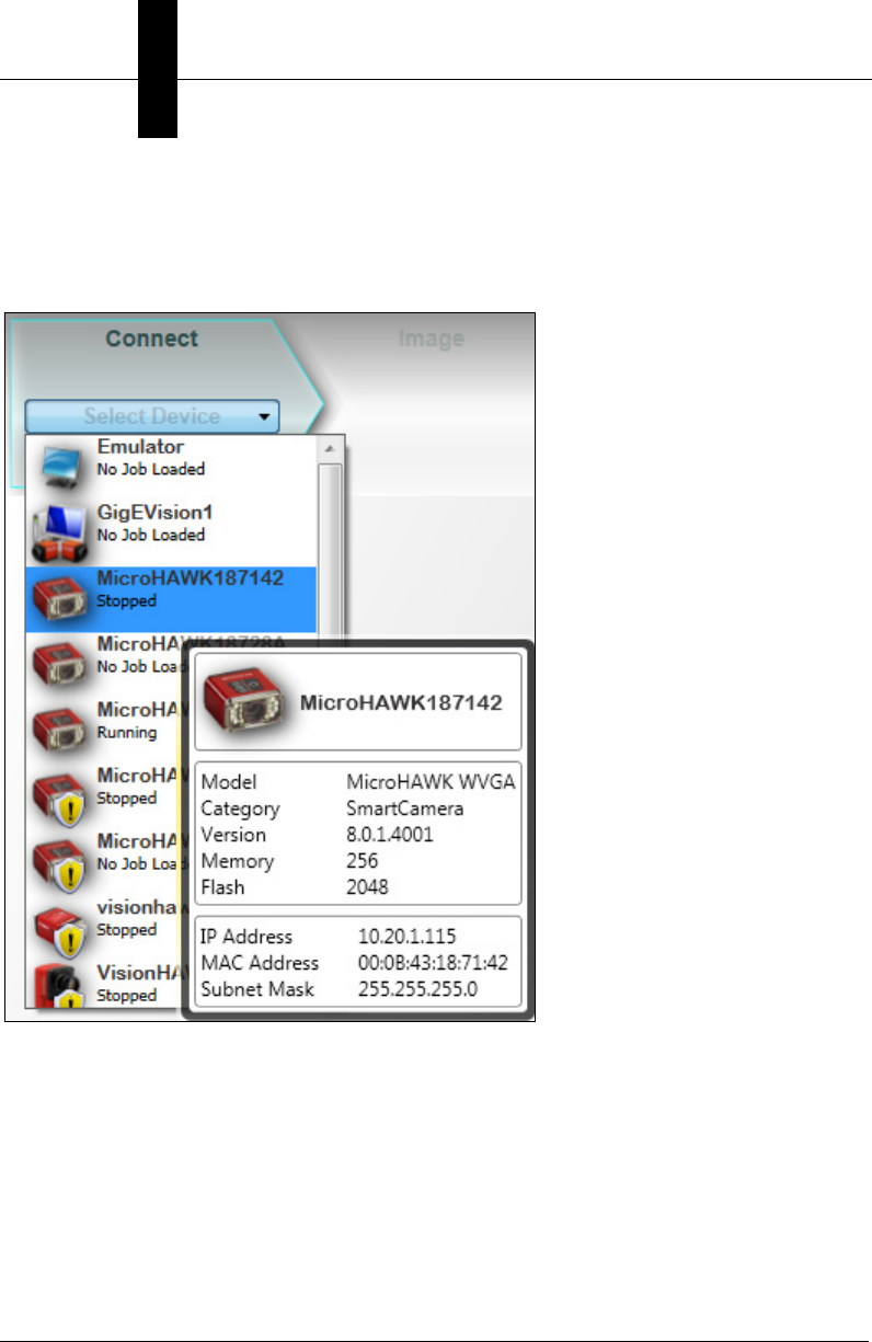
2. Select MicroHAWK in Connect View; Create a Job; Adjust Camera Settings
AutoVISION's Connect view allows you to select your device and configure its settings,
and to create a new job. The Select Device drop down menu provides a list of available
devices. Hover the mouse over a device to see its details.
Setting Up a Job in AutoVISION
Getting Started with
AutoVISION
3
MicroHAWK MV-20 / MV-30 / MV-40 Smart Camera Guide 3-5
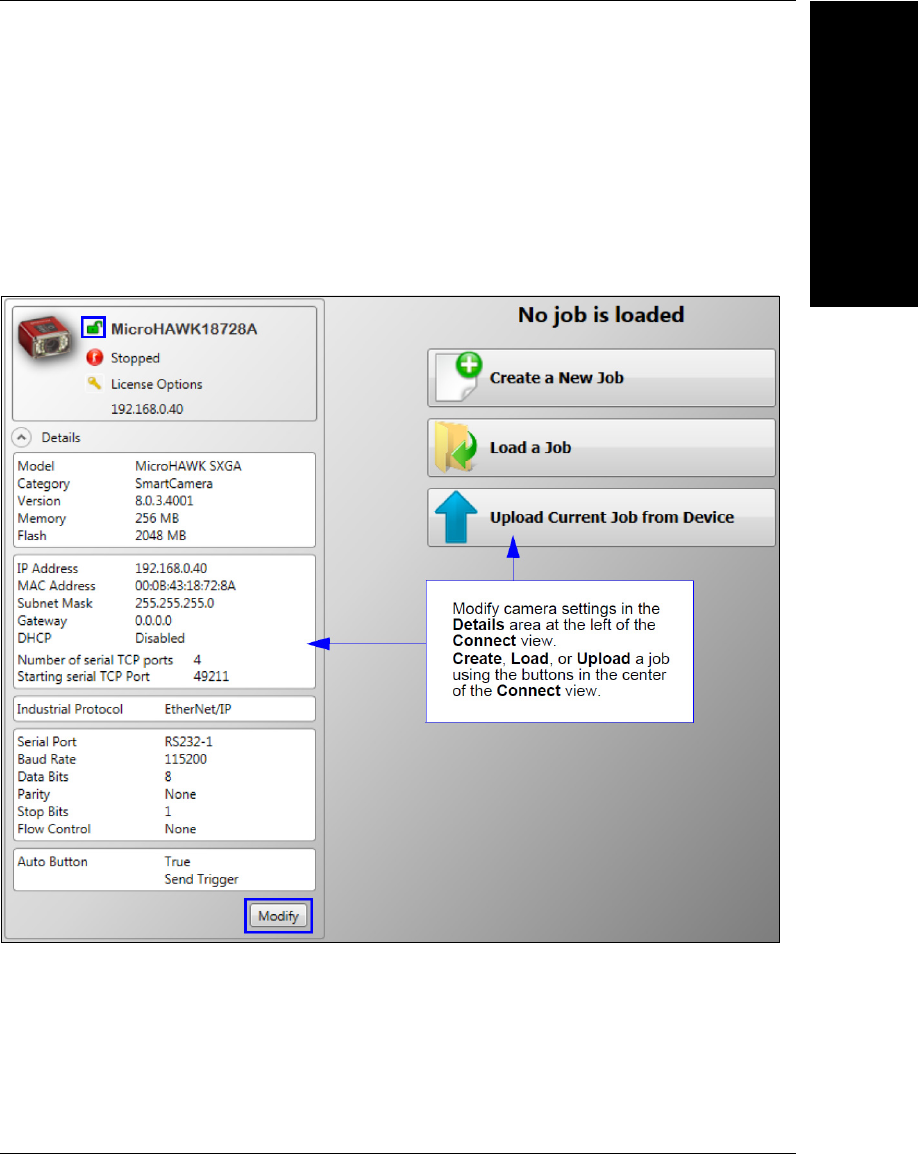
Click the lock icon to take control of the camera. When you have control of the camera, the
Modify button will appear beneath the camera settings. Click the Modify button to adjust
camera settings.
Note: If you are using an MV-20 or MV-30 with a USB cable, the driver has already
configured your PC address. If you are using an MV-40, you must set the PC to the same
IP range as the default IP address. Default IP address: 192.168.188.2. Set the PC to the
same IP range (example: 192.168.188.100).
Important: When modifying camera settings, you will need to enter a
username and
password for the camera if a password has been defined.
Chapter 3Getting Started with AutoVISION
3-6 MicroHAWK MV-20 / MV-30 / MV-40 Smart Camera Guide
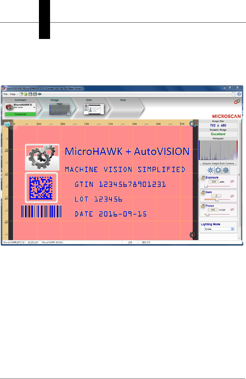
Once you have selected your camera, adjusted its settings, and created a new job, you
will move to the Image view. This view allows you to Auto Calibrate the camera, and to
manually adjust the camera's Exposure, Gain, and Focus, and also to set the Lighting
Mode (On, Off, or Strobe).
Setting Up a Job in AutoVISION
Getting Started with
AutoVISION
3
MicroHAWK MV-20 / MV-30 / MV-40 Smart Camera Guide 3-7
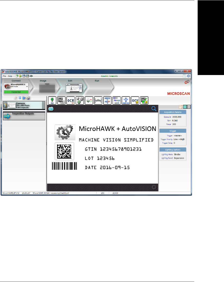
3. Edit the Job in AutoVISION
After you have created a new job, loaded a job from your PC, or uploaded a job from the
camera, you will proceed to the Edit view to refine your machine vision job. The Camera
parameters below the captured image allow you to set Gain, Exposure, Focus, Trigger,
and Lighting. Inspection Outputs options allow you to connect your job to the outside
world. This is also the view where you can add multiple tools to the job. The tool icons are
located above the main view area.
Chapter 3Getting Started with AutoVISION
3-8 MicroHAWK MV-20 / MV-30 / MV-40 Smart Camera Guide
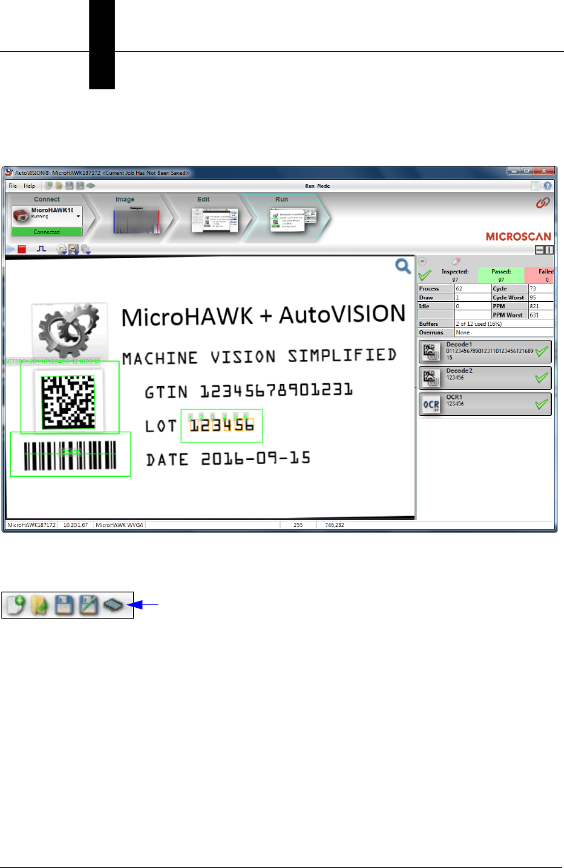
4. Run the Job in AutoVISION
Going to the
Run
view will automatically download your job to the camera and start it running.
5. Save the Job
Click the Save to Camera icon on the File menu bar to save the job to the MicroHAWK.

PROFINET I/O and IP Address Assignment
Getting Started with
AutoVISION
3
MicroHAWK MV-20 / MV-30 / MV-40 Smart Camera Guide 3-9
PROFINET I/O and IP Address Assignment
When PROFINET I/O is enabled on the unit, the PLC system may control the device
name, IP address, and subnet. When this is the case, it is impossible to communicate with
the unit from AutoVISION until the PLC has assigned an IP address. When the unit
disconnects from a PROFINET controller without disabling PROFINET, it may no longer
be reachable from AutoVISION. This condition may persist after cycling power on the unit
because the PROFINET I/O configuration is stored in non-volatile memory on the unit.
When disconnecting a unit from a PROFINET controller, it is recommended to always
disable PROFINET on the unit first, as this will erase the PROFINET configuration. The
unit will then remain reachable under its last known IP address.
It is possible to recover from loss of communication when PROFINET is left enabled, as
described below.
APIPA Address Assignment
When the unit fails to obtain a valid IP address, it will fall back on the APIPA (Automatic
Private Addressing) protocol after a timeout of 5 minutes.
To get an IP address, the unit will select an address at random in the range 169.254.1.0 to
169.254.254.255 with a subnet mask of 255.255.0.0. The client will then send an ARP
packet asking for the MAC address that corresponds to the randomly-generated IPv4
address. If any other machine is using that address, the client will generate another
random address and try again until it finds a free IP address.
The device network viewer can be used to discover units with an APIPA address, connect
to them, and update the IP address to a desired range.

Chapter 3Getting Started with AutoVISION
3-10 MicroHAWK MV-20 / MV-30 / MV-40 Smart Camera Guide

MicroHAWK MV-20 / MV-30 / MV-40 Smart Camera Guide 4-1
4
Optics and Lighting
4
CHAPTER 4 Optics and Lighting
This section describes the optical and illumination characteristics of
MicroHAWK MV-20, MV-30, and MV-40 Smart Cameras.

Chapter 4Optics and Lighting
4-2 MicroHAWK MV-20 / MV-30 / MV-40 Smart Camera Guide
Optics
The monochrome and color versions of the MicroHAWK MV-20, MV-30, and MV-40 have a
built-in CMOS sensor, available in Standard Density or High Density optics.
MV-20 Fixed Focus
MV-20 FOV Chart Fixed Focus Lens Type
Camera-to-Part
Distance SD - FOV (mm) HD - FOV (mm) UHD - FOV (mm)
mm inch Width Height Width Height Width Height
WVGA
50 1.97 49 31 34 22 15 10
64 2.52 61 39 42 27 19 12
1024.02946065412919
190 7.48 170 109 118 75 53 34
300 11.81 265 169 184 118 83 53
400 15.75 352 225 244 156 110 70
SXGA
50 1.97 52 39 36 27 16 12
64 2.52 65 48 45 34 20 15
102 4.02 100 75 69 52 31 23
190 7.48 181 136 125 94 57 43
300 11.81 282 212 196 147 88 66
400 15.75 375 281 260 195 117 88
QSXGA
50 1.97 49 37 34 26 15 12
64 2.52 62 46 43 32 19 14
1024.02957166493022
190 7.48 173 129 120 89 54 40
300 11.81 270 201 187 140 85 63
400 15.75 358 267 248 185 112 84

Optics
Optics and Lighting
4
MicroHAWK MV-20 / MV-30 / MV-40 Smart Camera Guide 4-3
MV-30 and MV-40 Fixed Focus
MV-30/40 FOV Chart Fixed Focus Lens Type
Camera-to-Part
Distance SD - FOV (mm) HD - FOV (mm) UHD - FOV (mm)
(mm) (inch) Width Height Width Height Width Height
WVGA
50 1.97 49 32 34 22 15 10
64 2.52 62 39 43 27 19 12
1024.02956066423019
190 7.48 171 109 118 76 54 34
300 11.81 266 170 185 118 83 53
400 15.75 353 225 245 156 111 71
SXGA
50 1.97 53 39 36 27 16 12
64 2.52 66 49 45 34 21 15
102 4.02 101 75 70 52 32 24
190 7.48 182 136 126 95 57 43
300 11.81 283 213 196 147 89 67
400 15.75 376 282 260 195 118 88
QSXGA
50 1.97 50 37 35 26 16 12
64 2.52 63 47 43 32 20 15
1024.02967267503022
190 7.48 174 130 121 90 54 41
300 11.81 271 202 188 140 85 63
400 15.75 359 268 249 186 113 84

Chapter 4Optics and Lighting
4-4 MicroHAWK MV-20 / MV-30 / MV-40 Smart Camera Guide
MV-30 and MV-40 Autofocus
Sensor Table
MV-30/40 FOV Chart Autofocus Lens Type
Camera-to-Part
Distance SD - FOV (mm) HD - FOV (mm) UHD - FOV (mm)
(mm) (inch) Width Height Width Height Width Height
WVGA
50 1.97 46 29 33 21 15 10
64 2.52 57 37 42 27 19 12
102 4.02 88 56 64 41 30 19
190 7.48 159 101 115 74 54 34
300 11.81 247 158 180 115 83 53
400 15.75 328 209 238 152 111 71
SXGA
50 1.97 49 37 36 27 16 12
64 2.52 61 46 44 33 21 15
102 4.02 93 70 68 51 32 24
190 7.48 169 127 123 92 57 43
300 11.81 263 197 191 144 89 67
400 15.75 349 262 254 190 118 88
QSXGA
50 1.97 47 35 34 25 16 12
64 2.52 58 43 42 32 20 15
102 4.02 89 67 65 48 30 22
190 7.48 161 120 117 87 54 41
300 11.81 252 187 183 136 85 63
400 15.75 334 249 243 181 113 84
Pixels (H x V) Shutter Frames per Second
(Standard / High)
WVGA 752 x 480, 0.3 MP, Mono Global 10 fps / 60 fps
SXGA 1280 x 960, 1.2 MP, Mono Global 10 fps / 42 fps
QSXGA 2592 x 1944, 5 MP, Color Rolling 5 fps
Illumination
Optics and Lighting
4
MicroHAWK MV-20 / MV-30 / MV-40 Smart Camera Guide 4-5
Illumination
Inner LEDs: 4 white, 4 red (625 nm nominal)
Outer LEDs: 8 high-output white or red (617 nm nominal)
Note: MV-20 only has inner LEDs. MV-30 and MV-40 have both inner and outer LEDs.
Options are available for IR and blue outer LEDs.
LED Modules
Description Left P/N Right P/N LED P/N Wavelength
Expansion, Red 43-9500055-01 43-9500056-01 LA E65F-CAEB-24-1 617 nm
Expansion, White 43-9500055-02 43-9500056-02 NFSW036BLT b3-b6/P9-P12 N/A
Expansion, IR 43-9500055-03 43-9500056-03 SFH 4259S 850 nm
Expansion, Blue 43-9500055-04 43-9500056-04 LB E63C-T2V2-35-34 469 nm
Chapter 4Optics and Lighting
4-6 MicroHAWK MV-20 / MV-30 / MV-40 Smart Camera Guide
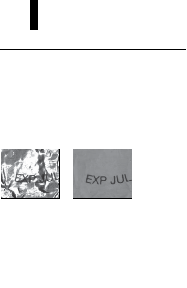
Machine Vision Lighting Principles
Proper lighting is critical to the success of a machine vision application. The MicroHAWK
features integrated lighting (built-in red LEDs for monochrome sensors and white LEDs for
color sensors). Depending on the requirements of your application, you may also need
external lighting from Microscan’s NERLITE family of machine vision lighting products.
Consider the following when setting up your application:
• Is the surface of the object flat, slightly bumpy, or very bumpy?
• Is the surface matte or shiny?
• Is the object curved or flat?
• What is the color of the object or area being inspected?
• Is the object moving or stationary?
Machine vision lighting should maximize contrast of the areas or features being inspected
while minimizing the contrast of everything else.
Before correct lighting After correct lighting with a
NERLITE Illuminator
MicroHAWK MV-40 External Illumination Control and Wiring
Optics and Lighting
4
MicroHAWK MV-20 / MV-30 / MV-40 Smart Camera Guide 4-7
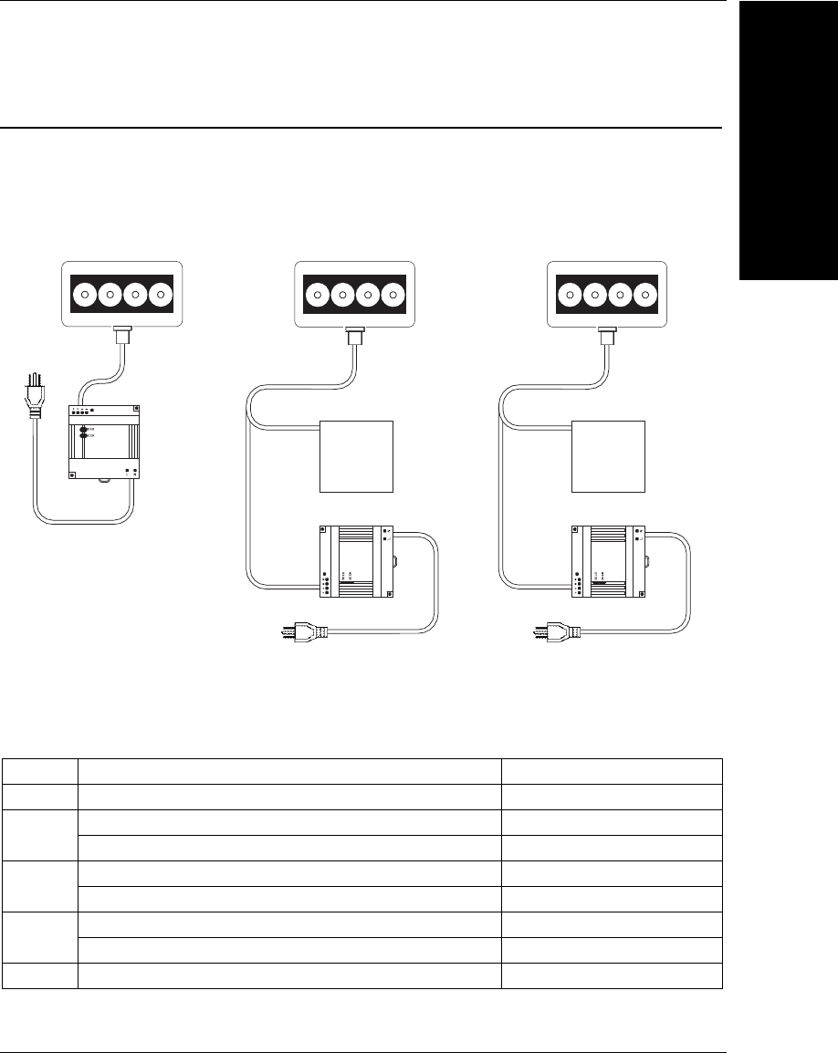
MicroHAWK MV-40 External Illumination Control and Wiring
The MicroHAWK MV-40 Smart Camera supports external lighting with Microscan’s
NERLITE Smart Series lights. The diagrams below demonstrates how the camera and
light can be configured. The light is controlled using the Lighting control in the Camera
configuration settings of AutoVISION software.
Item Description Part Number
1
MAX Series Lights NER-011660XXXG
2
Power Supply DSP100 24VDC 4.2A DIN Mount 97-000006-01
Power Supply DSP60 24VDC 2.5A DIN Mount NER-011504100
3
Cable, 5P M12 Socket To Flying Leads, 3M 61-000186-01
Cable, 5P M12 Socket To Flying Leads, 5M 61-000187-01
4
Cable, 5P M12 Plug To 5P M12 Socket, 1M 61-000184-01
Cable, 5P M12 Plug To 5P M12 Socket, 3M 61-000185-01
5
Cable, Power Smart Series to QX-1 61-000204-01
Optics and Lighting
3
2
Figure A
MAX Series Illuminator
with power supply
1
3
2
Customer
supplied
signal source
3
Customer
supplied
signal source
11
Figure C
MAX Series Illuminator
with customer supplied
strobe trigger
signal source
Figure B
MAX Series Illuminator with
customer supplied dimming
or on-off signal source
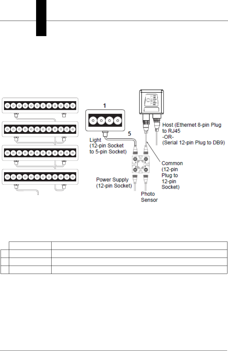
Chapter 4Optics and Lighting
4-8 MicroHAWK MV-20 / MV-30 / MV-40 Smart Camera Guide
QX-1 Interface
In Strobe mode, the external illuminator is strobed with the exposure of the camera to
maximize light for the short exposure times needed in dynamic applications.
ON/OFF allows the external illuminator to be enabled and disabled using the MicroHAWK
MV-40’s I/O.
Operation Cable
1
Strobe 61-000218-01, Smart Series-to-QX-1, Strobe, NPN
2
ON/OFF 61-000207-01, Smart Series-to-QX-1, ON/OFF
3
Continuous ON 61-000204-01, Smart Series-to-QX-1, Continuous
Figure D
MAX Series Illuminator in a daisy
chain configuration. See figures
A, B, or C for the correct power
supply and signal connections for
your application.
1
4
4
4
3
Figure E
MAX Series Illuminators with QX-1 Interface Device.
Note: Figure E is not compatible with daisy chaining.
Powering more than one MAX via the QX-1 will exceed
the QX-1’s current capacity.

MicroHAWK MV-40 External Illumination Control and Wiring
Optics and Lighting
4
MicroHAWK MV-20 / MV-30 / MV-40 Smart Camera Guide 4-9
Wiring for Strobe Illumination (NPN)
Warning: Contact between Pin 5 (gray wire) and any ground or voltage source less than
or equal to 3.5VDC may cause erratic operation in this configuration. Contact between Pin
5 (gray wire) and any voltage source greater than 3.5VDC will damage the illuminator.
* Insulate Pin 5 (gray wire)
MicroHAWK MV-40
Connector A
Smart Series Illuminator
Connector
Smart Series Illuminator
Pin Signal Name
1
+24VDC
2
Trigger –
3
DC Ground
4
Trigger +
5
Dim
MicroHAWK (Connector A)
Pin Signal Name
2
Power
6
Output 3
7 and 12 Ground and Output Common
2
Power
No Connection* N/A
to
to
to
to
to
Optics and Lighting
Chapter 4Optics and Lighting
4-10 MicroHAWK MV-20 / MV-30 / MV-40 Smart Camera Guide
Wiring for Strobe Illumination (PNP)
Warning: Contact between Pin 5 (gray wire) and any ground or voltage source less than
or equal to 3.5VDC may cause erratic operation in this configuration. Contact between Pin
5 (gray wire) and any voltage source greater than 3.5VDC will damage the illuminator.
* Insulate Pin 5 (gray wire)
MicroHAWK MV-40
Connector A
Smart Series Illuminator
Connector
Smart Series Illuminator
Pin Signal Name
1
+24VDC
2
Trigger –
3
DC Ground
4
Trigger +
5
Dim
MicroHAWK (Connector A)
Pin Signal Name
2 and 12
Power and Output Common
7
Ground
7 Ground
6
Output 3
No Connection* N/A
to
to
to
to
to
MicroHAWK MV-40 External Illumination Control and Wiring
Optics and Lighting
4
MicroHAWK MV-20 / MV-30 / MV-40 Smart Camera Guide 4-11
Wiring for ON/OFF Illumination (NPN Only)
Warning: Contact between Pin 5 (gray wire) and any voltage source greater than 3.5VDC
will damage the illuminator.
* Insulate Pin 5 (gray wire)
MicroHAWK MV-40
Connector A
Smart Series Illuminator
Connector
Smart Series Illuminator
Pin Signal Name
1
+24VDC
2
Trigger –
3
DC Ground
4
Trigger +
5
Dim
MicroHAWK (Connector A)
Pin Signal Name
2
Power
7 and 12 Ground and Output Common
7 and 12 Ground and Output Common
2
Power
6 Output 3
to
to
to
to
to
Chapter 4Optics and Lighting
4-12 MicroHAWK MV-20 / MV-30 / MV-40 Smart Camera Guide
Wiring for Continuous Illumination
Warning: Contact between Pin 5 (gray wire) and any ground or voltage source less than
or equal to 3.5VDC may cause erratic operation in this configuration. Contact between Pin
5 (gray wire) and any voltage source greater than 3.5VDC will damage the illuminator.
* Insulate Pin 5 (gray wire)
MicroHAWK MV-40
Connector A
Smart Series Illuminator
Connector
Smart Series Illuminator
Pin Signal Name
1
+24VDC
2
Trigger –
3
DC Ground
4
Trigger +
5
Dim
MicroHAWK (Connector A)
Pin Signal Name
2
Power
7
Ground
7
Ground
2
Power
No Connection* N/A
to
to
to
to
to

MicroHAWK MV-20 / MV-30 / MV-40 Smart Camera Guide A-1
A
Connector Pinouts
A
APPENDIX A Connector Pinouts
This section contains information about the MicroHAWK MV-20, MV-30,
and MV-40 Smart Camera’s connectors and pin assignments.
Appendix AConnector Pinouts
A-2 MicroHAWK MV-20 / MV-30 / MV-40 Smart Camera Guide
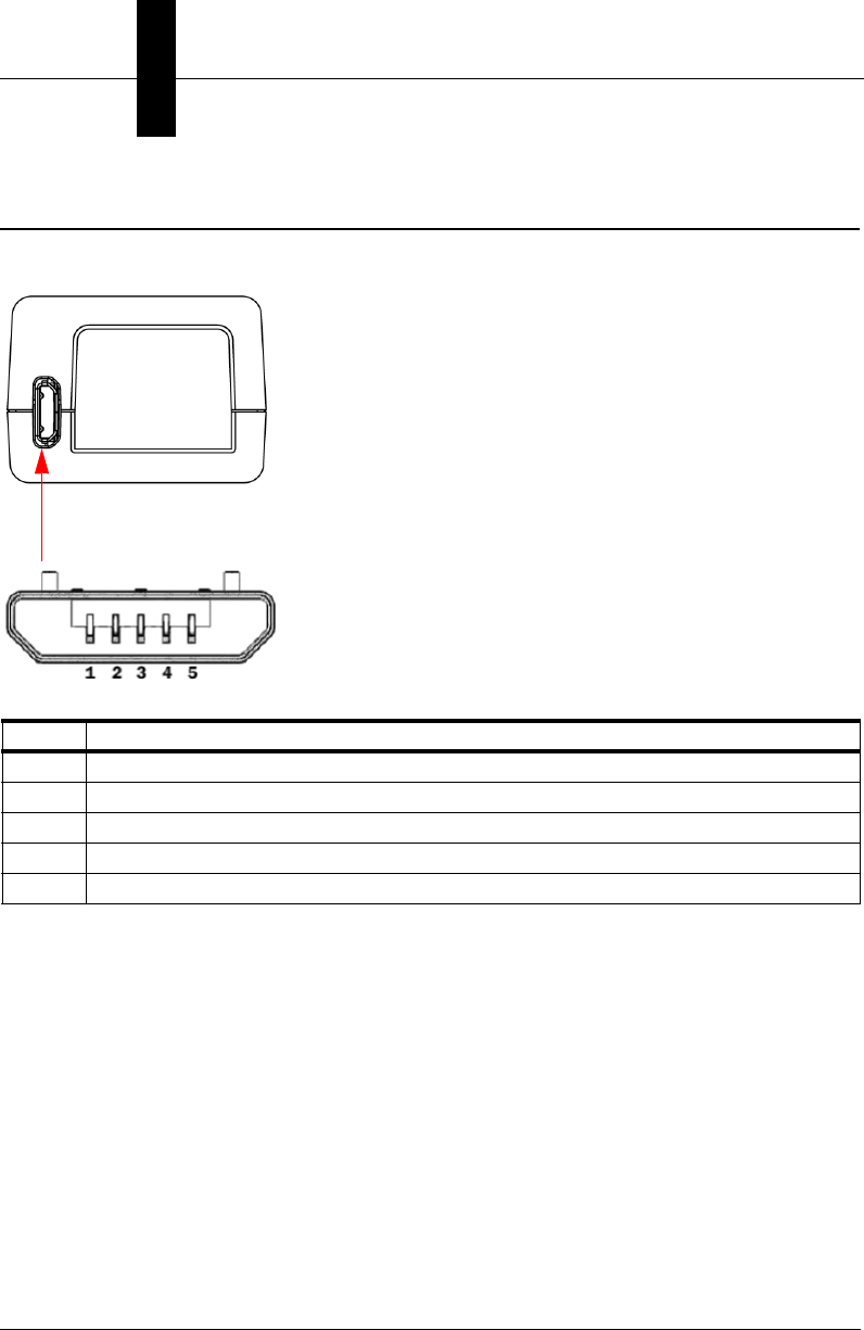
MV-20 Connector
Micro-USB Type B Socket
Pin Function
1 Vbus (5V)
2D–
3D+
4NC
5Ground
MicroHAWK MV-30 Smart Camera Connector
Connector Pinouts
A
MicroHAWK MV-20 / MV-30 / MV-40 Smart Camera Guide A-3
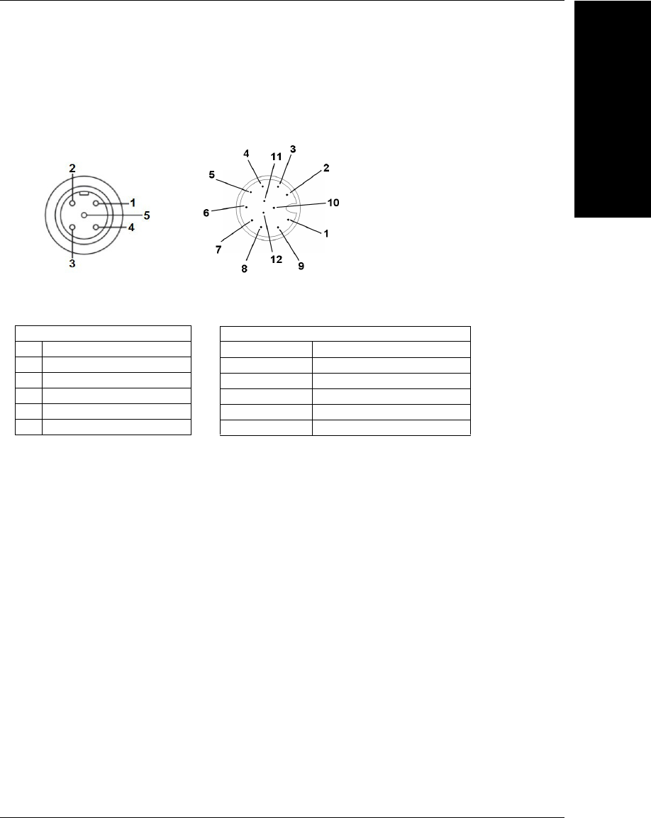
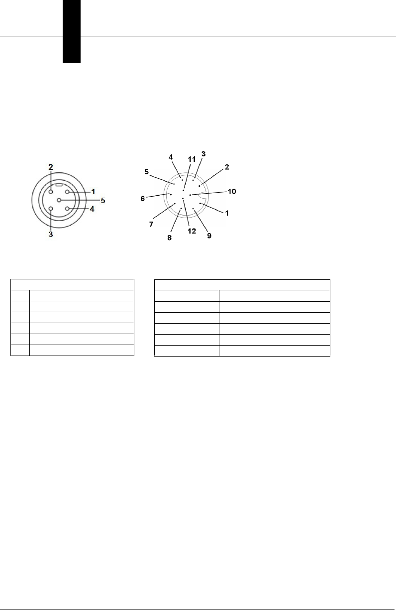
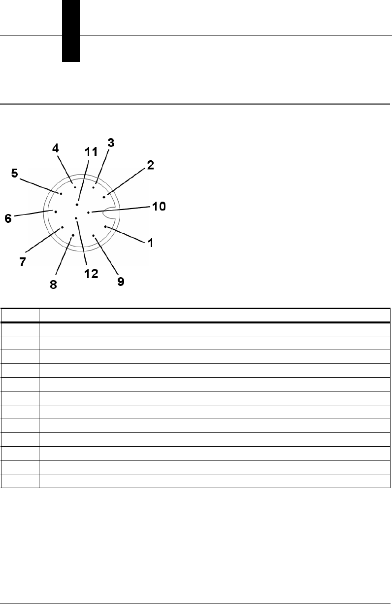
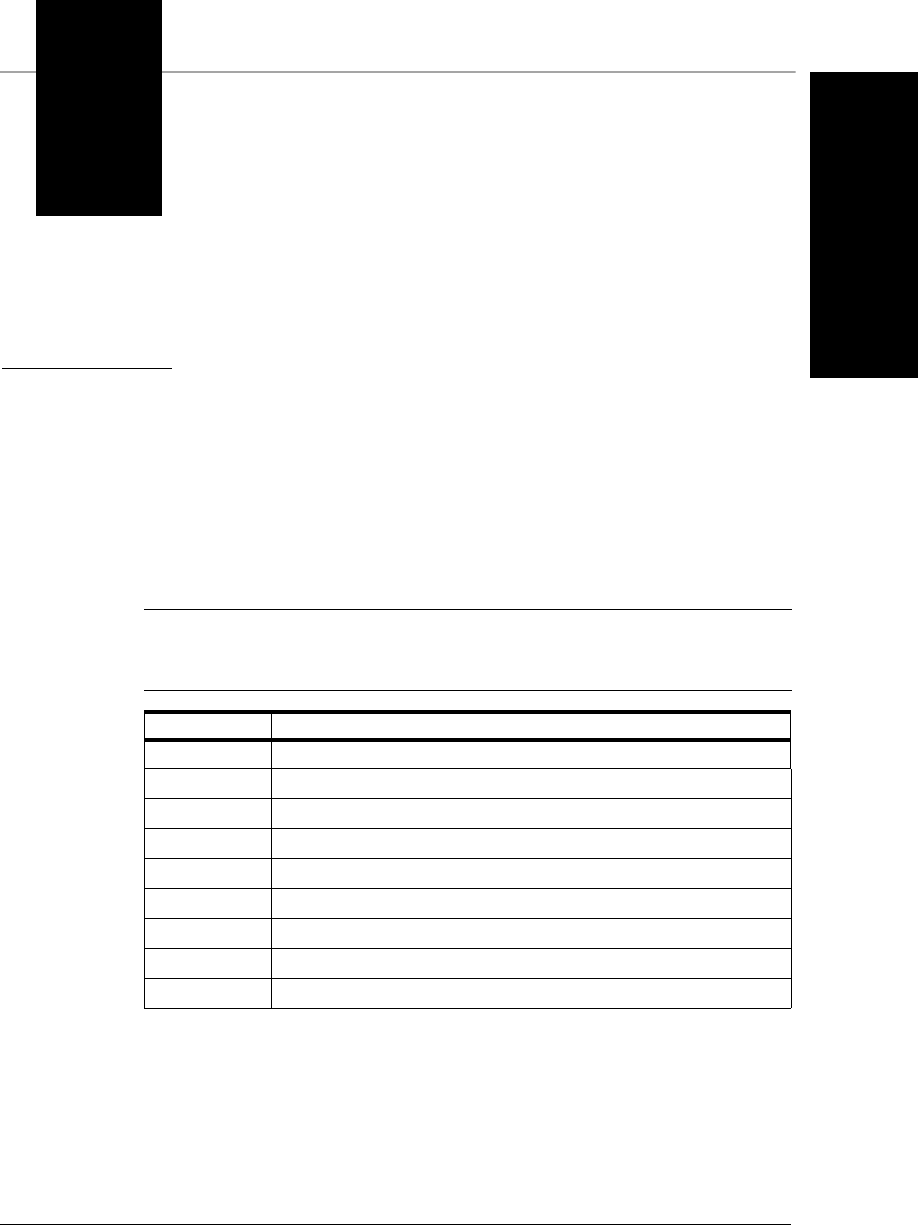
MV-30 Connector
High-Density 15-Pin D-Sub Socket
Appendix AConnector Pinouts
A-4 MicroHAWK MV-20 / MV-30 / MV-40 Smart Camera Guide
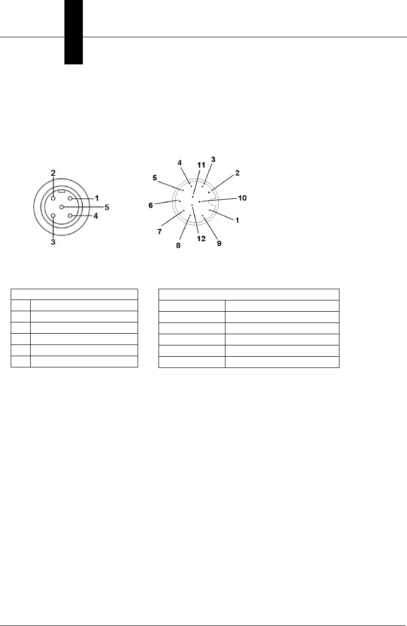
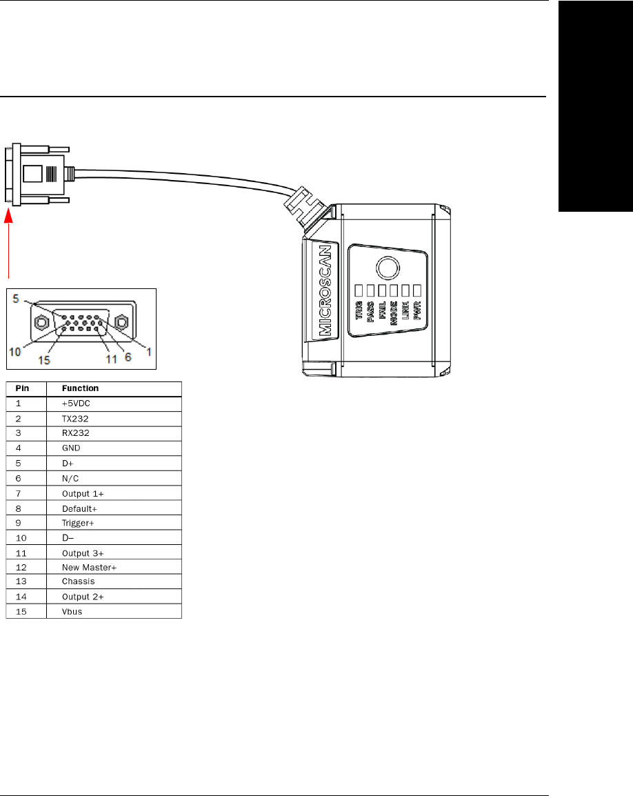
MV-40 Connector
Connector A – M12 12-Pin Plug – Power, I/O, and Serial
Pin Function
1 Trigger
2Power
3Default
4Input 1, New Master
5Output 1
6Output 3
7Ground
8Input Common
9RS-232 (Host RxD)
10 RS-232 (Host TxD)
11 Output 2
12 Output Common

MicroHAWK MV-40 Smart Camera Connector
Connector Pinouts
A
MicroHAWK MV-20 / MV-30 / MV-40 Smart Camera Guide A-5
Connector B – M12 8-Pin Socket – Ethernet
Pin Function
1V+
2V–
3V–
4TX (–)
5RX (+)
6TX (+)
7V+
8RX (–)
Connector Pinouts

Appendix AConnector Pinouts
A-6 MicroHAWK MV-20 / MV-30 / MV-40 Smart Camera Guide
MicroHAWK MV-20 / MV-30 / MV-40 Smart Camera Guide B-1
B
Cable Specifications
B
APPENDIX B Cable Specifications
This section contains information about cables for the MicroHAWK MV-20,
MV-30, and MV-40 Smart Cameras.
Note: Cable specifications are published for information only. Microscan
does not guarantee the performance or quality of cables provided by
other suppliers.
Part Number Description
61-9000034-01 Cable, USB A to Micro B, 6 ft., MV-20
61-9000045-01 Cable, USB A to Micro B, 3 ft., MV-20
61-9000037-01 Cable, DB15 to Ext. Power/RS-232, MV-30
61-9000038-01 Cable, DB15 to Ext. Power/USB, MV-30
61-9000039-01 Cable, DB15 to Ext. Power/USB, I/O, MV-30
61-9000043-01 Cable, DB15 to BUS Power USB, MV-30
61-9000102-01 Cable, DB15 to USB/RS-232 Triggered, MV-30
61-9000054-01 Cable, M12 12-Pin Socket to 9-Pin Socket and M12 Plug
61-9000088-01 Cable, M12 12-Pin Socket to USB Keyboard Wedge and M12 Plug
Appendix BCable Specifications
B-2 MicroHAWK MV-20 / MV-30 / MV-40 Smart Camera Guide
MV-20 Cables
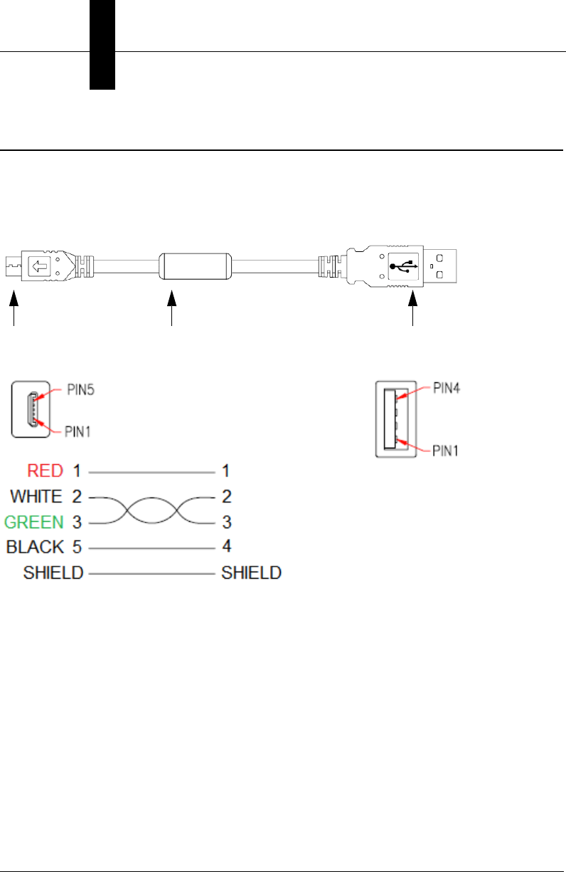
61-9000034-01/61-9000045-01 USB Type A-to-Micro B Cable
The 61-9000034-01/61-9000045-01 Micro-USB Type B plug to USB Type A plug cable is a
double-ended shielded ferrite core USB cable. 61-9000034-01 is 6 feet long, and 61-9000045-01
is 3 feet long. This cable is used for basic communications-only applications.
Micro-USB
Type B
Plug
USB
Type A
Plug
Shown with optional ferrite
core (98-9000035-01, Ferrite
Core Snap-On Kit for USB
Cable – required for Class B
Emissions)
MV-30 Cables
Cable Specifications
B
MicroHAWK MV-20 / MV-30 / MV-40 Smart Camera Guide B-3
MV-30 Cables
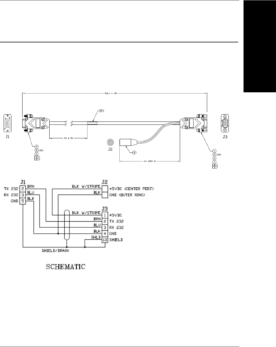
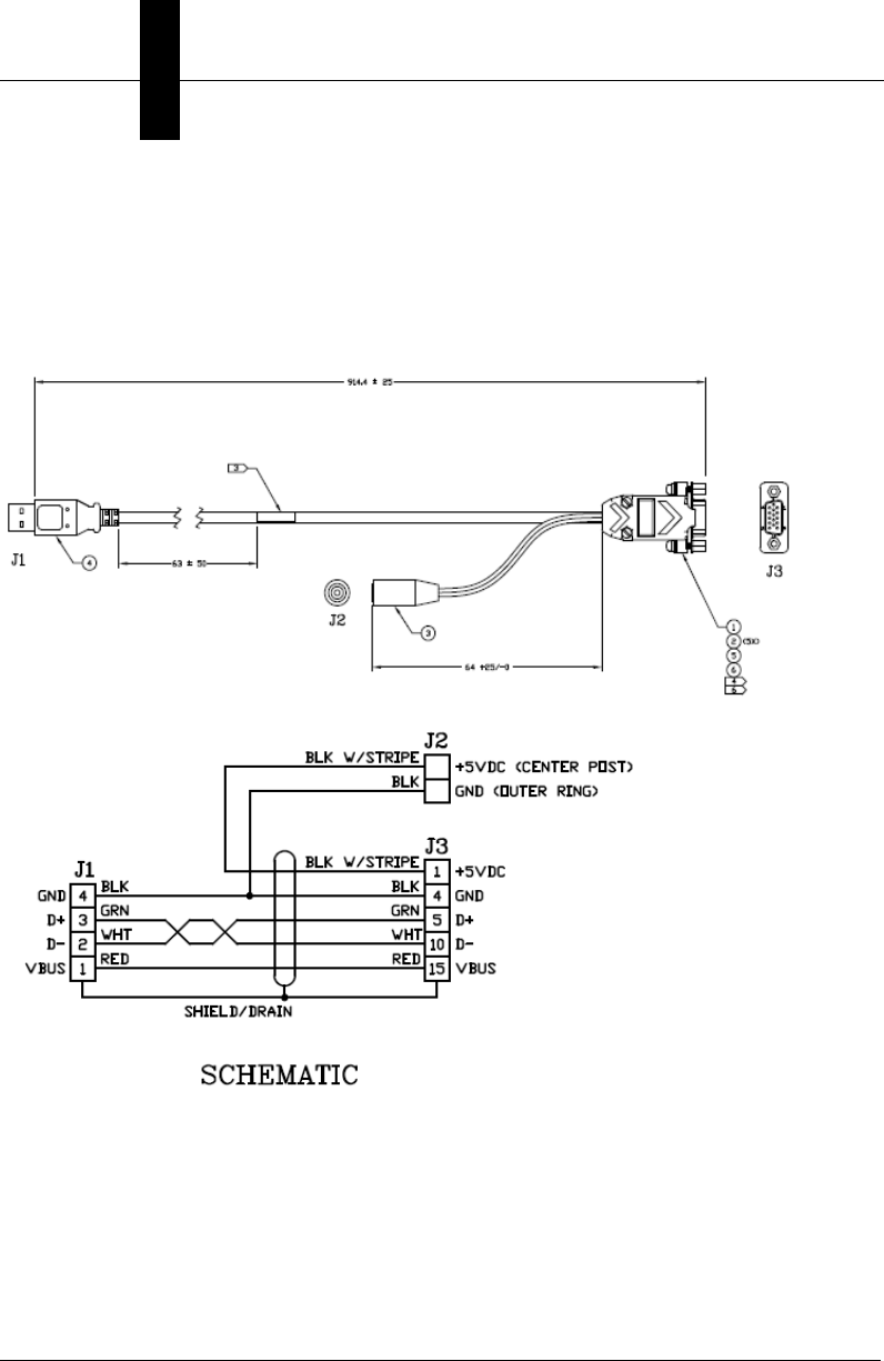
61-9000037-01 DB15 to Ext. Power/RS-232 Cable
The 61-9000037-01 DB15 to Ext. Power/RS-232 cable is cable with one end a 9-pin D-Sub
socket connector (J1) and the other end a DB15 (J3) extended Power/RS-232 (J2). This
cable is used for basic communications applications that require more light or use
higher-speed applications.
Appendix BCable Specifications
B-4 MicroHAWK MV-20 / MV-30 / MV-40 Smart Camera Guide
61-9000038-01 DB15 to Ext. Power/USB Cable
The 61-9000038-01 DB15 to ext. power/USB cable is a cable with one end a USB
connector(J1) and the other end a DB15 (J3) extended power/RS-232 (J2). This cable is
used for basic communications applications that require more light or for higher speed
applications.
MV-30 Cables
Cable Specifications
B
MicroHAWK MV-20 / MV-30 / MV-40 Smart Camera Guide B-5
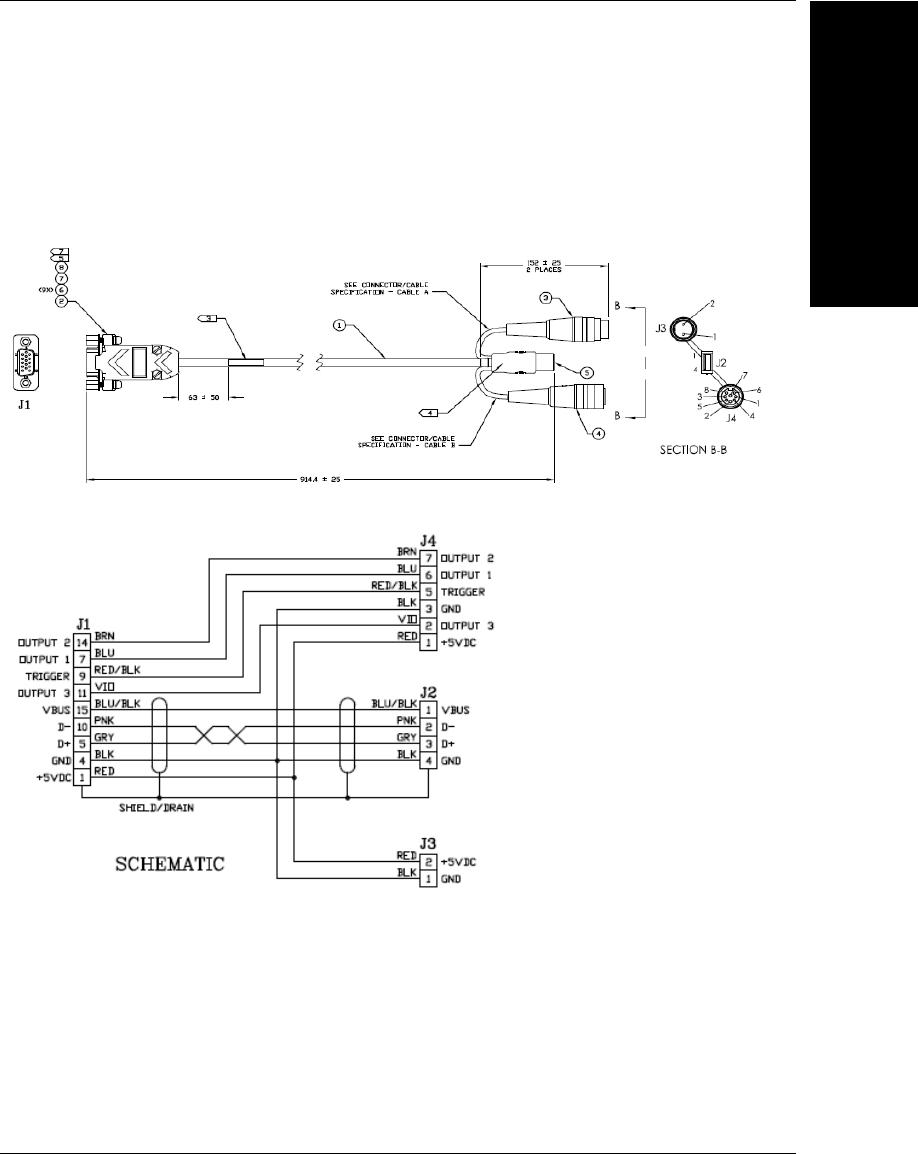
61-9000039-01 DB15 to Ext. Power/USB, I/O Cable
The 61-9000039-01 DB15 to ext. power/USB, I/O cable is a cable with one end a 15-pin
D-Sub socket connector (J1) and the other end a USB (J2) extended with a 2-pin socket
(J3) and an 8-pin socket (J4) connector. This cable is used for virtual LAN or RS-232 with
I/O applications, any speed with line stop or result indication.

Appendix BCable Specifications
B-6 MicroHAWK MV-20 / MV-30 / MV-40 Smart Camera Guide
61-9000043-01 DB15 to BUS Power USB Cable
The 61-9000043-01 DB15 to bus power USB cable is a double-ended cable; one end is
a 15-pin D-Sub socket (J1) and the other end is a USB plug (J2). This cable is used for
basic communications applications that require more light or for higher speed applications.
MV-30 Cables
Cable Specifications
B
MicroHAWK MV-20 / MV-30 / MV-40 Smart Camera Guide B-7
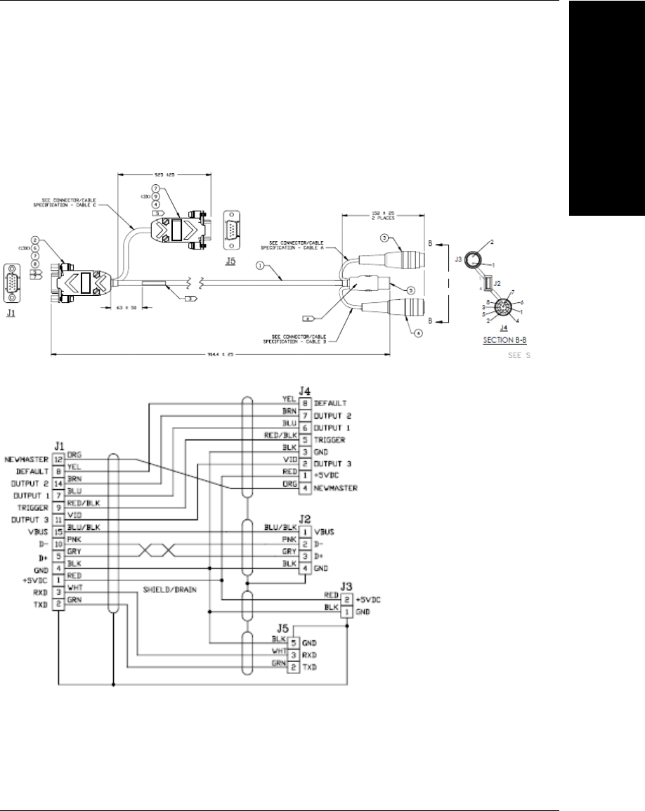
61-9000102-01 DB15 to USB/RS-232 Triggered Cable
The 61-9000102-01 DB15 to USB/RS-232 triggered cable is a cable with one end a 9-pin
(J5) and a 15-pin D-Sub socket connector (J1), and the other end a USB (J2) extended
with a 2-pin socket (J3) and an 8-pin socket (J4) connector. This cable is used for RS-232
applications with I/O for line stop or result indications.
Appendix BCable Specifications
B-8 MicroHAWK MV-20 / MV-30 / MV-40 Smart Camera Guide
MV-40 Cables
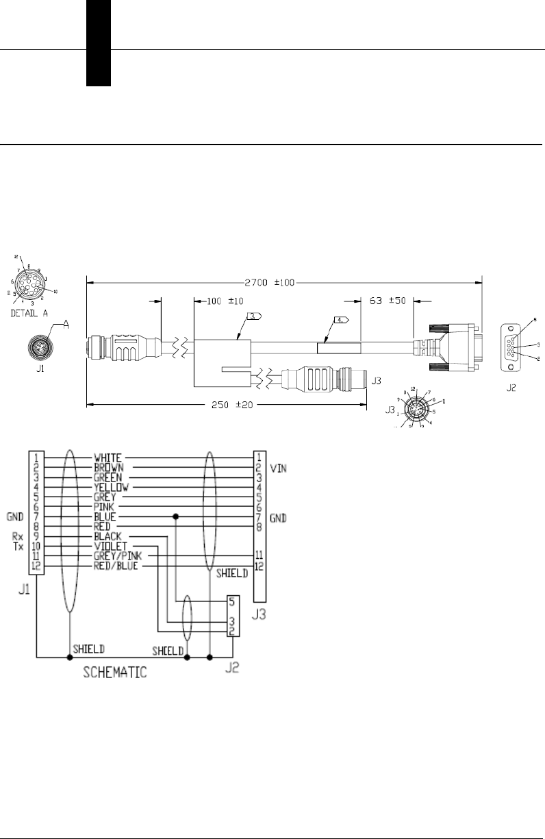
61-9000054-01 M12 12-Pin Socket to 9-Pin Socket and M12 Plug
The 61-9000054-01 M12 12-pin socket to 9-pin socket and M12 plug cable is a cable with
one end a 12-pin socket connector (J1) and the other end a 9-pin socket (J2) and an M12
plug (J3). This cable replaces common cord set, QX-1 and RS-232 cable with a single
cable option. It is used for both RS-232 and WebLink simultaneously.
MV-40 Cables
Cable Specifications
B
MicroHAWK MV-20 / MV-30 / MV-40 Smart Camera Guide B-9
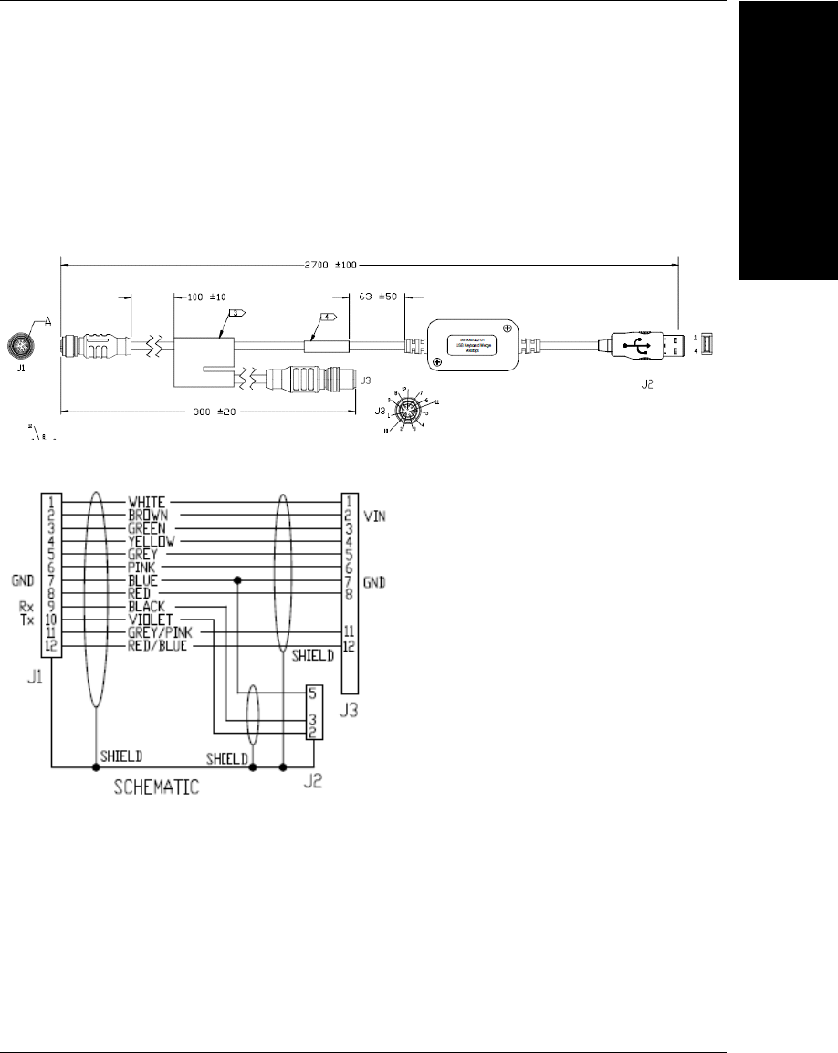
61-9000088-01 M12 12-Pin Socket to USB Keyboard Wedge and
M12 Cable
The 61-9000088-01 M12 12-pin socket to USB keyboard wedge and M12 cable is a cable
with one end a 12-pin socket connector (J1) and the other end a 98-9000022-01 USB
keyboard wedge (9600 bps) (J2) and an M12 plug (J3). This cable is used with
applications requiring keyboard input.
Appendix BCable Specifications
B-10 MicroHAWK MV-20 / MV-30 / MV-40 Smart Camera Guide
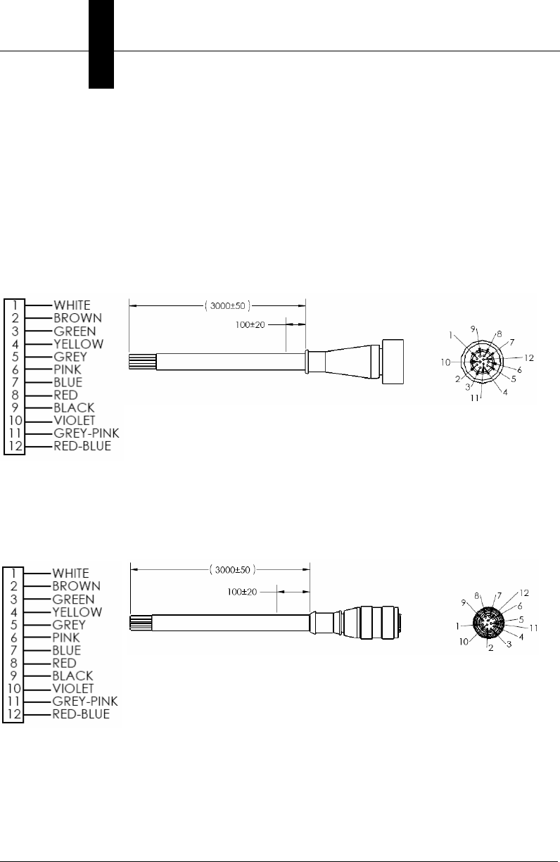
Pinouts for Cordsets with Flying Leads
Microscan offers two flying lead cordsets for use in hardware configurations:
• 61-000166-02 (Plug, Screw-On)
•61-000167-02 (Socket, Screw-On)
The diagrams below show the correspondence of wire colors to pins.
61-000166-02 – M12 12-Pin Plug to Flying Leads
61-000166-02 connects to Connector B (Serial) and QX-1 Connector 2.
61-000167-02 – Cordset, M12 12-Pin Socket to Flying Leads
61-000167-02 connects to Connector A and QX-1 Connectors
1 and 3.

MicroHAWK MV-20 / MV-30 / MV-40 Smart Camera Guide C-1
C
General
Specifications
C
APPENDIX C General Specifications
This section contains specifications for the MicroHAWK MV-20, MV-30,
and MV-40 Smart Cameras.

Appendix CGeneral Specifications
C-2 MicroHAWK MV-20 / MV-30 / MV-40 Smart Camera Guide
MV-20 General Specifications
MV-20 Dimensions, Enclosure
MV-20 Environmental, Emissions
MV-20 Electrical
MV-20 Connector, Communication, Illumination, Indicators
MV-20 Speed, Memory, Software, FTP Image Storage
MV-20 Sensor Options, Exposure Time, Shutter, Frames per Second
MV-20 Optics, Focus
Dimensions Enclosure
Height: 24 mm (0.94”)
Width: 34 mm (1.34”)
Length: 39 mm (1.54”)
Weight: 26 g (0.92 oz.)
IP40
Operating Temperature Storage Temperature Humidity Emissions
0° to 45° C
(32° to 113° F)
-50° to 75° C
(-58° to 167° F)
5% to 95%
(non-condensing) EN 55022:2010 Class A Limits
Electrical
5 VDC ± 5%, 350 mA at 5 VDC (typ.)
Connector Communication Illumination Indicators
Micro-B USB USB 2.0 High Speed,
Ethernet over USB/HID
Inner Red: 4 LEDs, 625 nm nominal
Inner White: 4 LEDs
Light Modes: Off, On, Strobe
Operating Life: 50,000 hours @ 25° C
Power LED, 2 Target Pattern
LEDs, 2 Inspection Passed
(Green Flash) LEDs
Speed Memory Software FTP Image Storage
400 MHz 2 GB Non-Volatile Flash,
256 MB RAM AutoVISION Sensor, AutoVISION, Visionscape Supported
Sensor Options Exposure Time Shutter Frames per Second
WVGA (Mono): CMOS 0.34 MP (752 x 480),
4.51 x 2.88 mm, 6 μm pixel size WVGA: 50 to 66,667 μs
Global
WVGA: Up to 52
SXGA (Mono): CMOS 1.2 MP (1280 x 960),
4.80 x 3.60 mm, 3.75 μm pixel size SXGA: 66 to 58,825 μsSXGA: Up to 40
QSXGA (Color): CMOS 5 MP (2592 x 1944),
4.536 x 3.402 mm, 1.75 μm pixel size QSXGA: 66 to 66,667 μs Rolling QSXGA: Up to 5
Optics Focus
Standard Density (SD): 5.2 mm SD, HD: Factory set to 50, 102, 190, or 300 mm
High Density (HD): 8.0 mm
Ultra-High Density (UHD): 16.0 mm UHD: Factory set to 64 or 400 mm

MicroHAWK MV-30 General Specifications
General
Specifications
C
MicroHAWK MV-20 / MV-30 / MV-40 Smart Camera Guide C-3
MV-30 General Specifications
MV-30 Dimensions, Enclosure
MV-30 Environmental, Emissions
MV-30 Electrical
MV-30 Connector, Communication, Discrete I/O, Illumination, Indicators
MV-30 Memory, Speed, Software, FTP Image Storage
MV-30 Sensor Options, Shutter, Exposure Time, Frames per Second
MV-30 Optics, Focus
Dimensions Enclosure
Height: 25 mm (0.98")
Width: 45 mm (1.77")
Length: 38 mm (1.50")
Weight without Cable: 46 g (1.62 oz.)
IP54, Aluminum
Operating Temperature Storage Temperature Humidity Emissions
0° to 45° C
(32° to 113° F)
-50° to 75° C
(-58° to 167° F)
5% to 95%
(non-condensing) EN 55022:2010 Class A Limits
Electrical
5 VDC ± 5%, 600 mA at 5 VDC (typ.)
Connector Comm. Discrete I/O Illumination Indicators
0.91 m
Cable with
High-Density
15-Pin D-Sub
Socket
RS-232,
USB 2.0
High-Speed,
Ethernet over
USB/HID
2 in/3 out: Trigger Input;
New Master Input: 5-28 V-
rated (0.16 mA @ 5 VDC);
Strobe Output; 2 General
Purpose Outputs: 5V TTL-
compatible, can sink 10 mA
and source 10 mA
Inner Red: 4 LEDs, 625 nm nominal
Inner White: 4 LEDs
Outer Red, White, Blue, or IR: 8 LEDs
Light Modes: Inner or Outer; Off, On, Strobe,
Power Strobe; Power Strobe for Outer LEDs only.
Not available when running under USB power.
Operating Life: 50,000 hours @ 25° C
TRIG, PASS,
FAIL, MODE,
LINK, PWR LEDs,
2 Target Pattern
LEDs, 2
Inspection Passed
(Green Flash)
LEDs
Memory Speed Software FTP Image Storage
2 GB Non-Volatile Flash,
256 MB RAM 800 MHz AutoVISION Sensor, AutoVISION, Visionscape Supported
Sensor Options Shutter Exposure Time Frames per Second
WVGA (Mono): CMOS 0.34 MP (752 x 480),
4.51 x 2.88 mm, 6 μm pixel size Global
WVGA: 50 to 66,667 μsWVGA: Up to 52
SXGA (Mono): CMOS 1.2 MP (1280 x 960),
4.80 x 3.60 mm, 3.75 μm pixel size SXGA: 66 to 58,825 μsSXGA: Up to 40
QSXGA (Color): CMOS 5 MP (2592 x 1944),
4.536 x 3.402 mm, 1.75 μm pixel size Rolling QSXGA: 66 to 66,667 μsQSXGA: Up to 5
Optics Focus
Fixed: Standard Density (5.2 mm); High Density (8.0 mm);
Ultra-High Density (16.0 mm)
Fixed: Factory set to 50, 102, 190, or 300 mm (SD, HD);
64 or 400 mm (UHD)
Autofocus: Standard Density (5.2 mm); High Density (7.7 mm);
Ultra-High Density (16.0 mm)
Autofocus: Software-adjustable 50 to 300 mm (SD, HD);
40 to 150 mm (UHD)
Appendix CGeneral Specifications
C-4 MicroHAWK MV-20 / MV-30 / MV-40 Smart Camera Guide
MV-40 General Specifications
MV-40 Dimensions, Enclosure
MV-40 Environmental, Emissions
MV-40 Electrical
MV-40 Connector, Communication, Discrete I/O, Illumination, Indicators
MV-40 Speed, Memory, Software, FTP Image Storage
MV-40 Sensor Options, Shutter, Exposure Time, Frames per Second
MV-40 Optics, Focus
Dimensions Enclosure
Height: 25 mm (0.98")
Width: 45 mm (1.77")
Length: 45 mm (1.77")
Weight: 68 g (2.40 oz.)
IP65/67, Aluminum
Operating Temperature Storage Temperature Humidity Emissions
0° to 45° C
(32° to 113° F)
-50° to 75° C
(-58° to 167° F)
5% to 95%
(non-condensing) EN 55022:2010 Class A Limits
Electrical
4.75-30 VDC, 200 mV p-p max ripple, 150 mA at 24 VDC (typ.)
Connector Passive PoE Comm. Discrete I/O Illumination Indicators
M12 12-Pin
Power,
M12 8-Pin
Ethernet
24 V Passive
Power over
Ethernet, Type
B; Requires
passive PoE
power supply
RS-232,
Ethernet
TCP/IP,
EtherNet/IP,
PROFINET
I/O
2 in/3 out: Optoisolated
Trigger Input; New Master
Input: Bi-directional,
Optoisolated, 1-28 V-rated
(10 mA @ 28 VDC); Strobe
Output, 2 General Purpose
Outputs: Bi-directional,
Optoisolated, 1-28 V-rated
(ICE < 100 mA @ 24 VDC,
current limited by user)
Inner Red: 4 LEDs, 625 nm
nominal
Inner White: 4 LEDs
Outer Red, White, Blue, or IR:
8 LEDs
Light Modes: Inner or Outer; Off,
On, Strobe, Power Strobe; Power
Strobe for Outer LEDs only
Operating Life: 50,000 hours @
25° C
TRIG, PASS,
FAIL, MODE,
LINK, PWR LEDs,
2 Target Pattern
LEDs, 2
Inspection Passed
(Green Flash)
LEDs
Speed Memory Software FTP Image Storage
800 MHz 2 GB Non-Volatile Flash,
256 MB RAM AutoVISION Sensor, AutoVISION, Visionscape Supported
Sensor Options Shutter Exposure Time Frames per Second
WVGA (Mono): CMOS 0.34 MP (752 x 480),
4.51 x 2.88 mm, 6 μm pixel size Global
WVGA: 50 to 66,667 μsWVGA: Up to 52
SXGA (Mono): CMOS 1.2 MP (1280 x 960),
4.80 x 3.60 mm, 3.75 μm pixel size SXGA: 66 to 58,825 μsSXGA: Up to 40
QSXGA (Color): CMOS 5 MP (2592 x 1944),
4.536 x 3.402 mm, 1.75 μm pixel size Rolling QSXGA: 66 to 66,667 μsQSXGA: Up to 5
Optics Focus
Fixed: Standard Density (5.2 mm); High Density (8.0 mm);
Ultra-High Density (16.0 mm)
Fixed: Factory set to 50, 102, 190, or 300 mm (SD, HD);
64 or 400 mm (UHD)
Autofocus: Standard Density (5.2 mm); High Density (7.7 mm);
Ultra-High Density (16.0 mm)
Autofocus: Software-adjustable 50 to 300 mm (SD, HD);
40 to 150 mm (UHD)

MicroHAWK MV-20 / MV-30 / MV-40 Smart Camera Guide D-1
D
Serial Commands
D
APPENDIX D Serial Commands
This section provides descriptions of the serial commands that can be
sent to the camera via TCP (Telnet) port, AutoVISION Terminal, or
HyperTerminal.

Appendix DSerial Commands
D-2 MicroHAWK MV-20 / MV-30 / MV-40 Smart Camera Guide
Serial Command Syntax
< > = Required argument. Replace appropriately.
For example:
-u <DB_User_name> becomes -u av where av replaces DB_User_name.
| = Mutually exclusive arguments. Choose one from the list.
{ } = Used with | to specify a list of choices for an argument.
[ ] = Optional parameter.
Important: Unless otherwise stated, commands will respond with !OK on success and
!ERROR on failure.
AUTOCAL [-exp={0|1}] [-expval={60-100000}] [-gain={0|1}] [-gainval
={0-100}] [-focus={0|1}] [-focval{0-9999}]
Initiates camera calibration of gain, exposure, and focus. Each parameter is independent.
Ranges are device-dependent.
CHECKSUM {BOOT | KERNEL | BOOTPARAM}
Gets a checksum on an individual part of the system.
DELETE <key>
Deletes a key.
FINDCHILDREN [-parent=clsid] [-child=symname]
Retrieves the children of type clsid for the symbolic parent.
FINDPARENT [-parent=clsid] [-child=symname]
Retrieves the first parent of type clsid for the symbolic child.
FINDSTEPS [-type=clsid]
Retreives a csv step list in symbolic form of the type passed in the current job.
GET {tagname|service|service.tagname}
Gets value of a global tag.
The tagname must correspond to one of the supported tags within the device. Use the
INFO command to get a full list of tags and services, as well as attributes of the tag and list
of subtags.
The command is terminated by a carriage return and/or line feed character.
Include an index to get a single value from an array such as GET int1. If the index is
omitted, the full array of values will be returned in a comma-separated list of values.

Serial Commands
D
MicroHAWK MV-20 / MV-30 / MV-40 Smart Camera Guide D-3
Send Get {tagname|service.tagname|service} to get the value of a tag within the global
data service. To get the value of a tag within another service, prefix the tagname with the
service name. For example, a GET <service.tagname> command such as GET
eip.input for the EIP input assembly.
The AVP service allows retrieval of step and datum information from the job tree using
forward slash ‘/’ in the symbolic name path. GET avp/insp1/snapshot1/status paths are
not case-sensitive and do not need to be fully qualified if unique.
GET avp/snapshot1/status will return the same result if there is only one inspection.
When issued against a step, GET avp/snapshot1 will return the values for all datums.
Success Return: On success will return the value stored in the tag.
For example:
ABCD
Fail Return: On failure will return !ERROR followed by the reason for the failure.
For example:
!ERROR Tag matchstring66 not found
GETIMAGE <-transfer=ymodem> [-format={jpg|png}] [-quality={0-100}]
[-woi=left,top,right,bottom] [-inspection=n]
Initiates serial transfer of inspection image (RS-232 only).
Note: This command always returns the last (most recent) image.
-transfer=ymodem is currentlynot optional - only Ymodem protocol is supported.
-format={jpg|png} specifies the format of the image. If omitted, the image format is JPG.
-quality=n specifies a JPG compression quality of n less than or equal to 100. The default
quality is 80 if not specified.
Note: The PNG format provides lossless image compression. If format is set to PNG, the
quality setting does not apply.
woi=left,top,right,bottom specifies a rectangular area of the image to be included in the
output image. If omitted, the full image buffer is returned.
-inspection=n specifies the inspection from which to retrieve an image. The image will be
from the first snapshot within that inspection. If not specified, the image will be from the
first inspection that does contain a snapshot.
The following example will retrieve an image from the camera with these settings: Protocol:
ymodem; Format: png; Quality: N/A; Inspection: second inspection.
GETIMAGE –transfer=ymodem –format=png –inspection=2
The following example will retrieve an image from the camera with these settings: Protocol:
ymodem; Format: jpg (default); Quality: 50; Inspection: first inspection (default).
GETIMAGE –transfer=ymodem –quality=50

Appendix DSerial Commands
D-4 MicroHAWK MV-20 / MV-30 / MV-40 Smart Camera Guide
HELP
Returns a list of all serial commands showing correct syntax and functionality descriptions.
INFO [tagname|service]
Gets information about a tag or service.
INFO with no arguments gets a list of services.
INFO <service> gets a list of tags in that service.
INFO <service.tagname> gets attributes of the tag as well as a list of subtags.
The AVP service allows retrieval of step and datum information from the job tree using
forward slash ‘/’ in the symbolic name path. INFO avp/insp1/snapshot1/status paths are
not case-sensitive and do not need to be fully qualified if unique.
INFO avp/snapshot1/status will return the same result if there is only one inspection.
When issued against a step, INFO avp/snapshot1 returns properties of the step, a list of
child datums, and a list of child steps. Child steps are indicated by a trailing forward slash.
JOBBOOT [-slot=]<n>
Sets bootup job slot n (RS-232 only).
JOBDELETE {[-slot=]n|-all}
Deletes job in slot n, or all jobs if -all.
Important: Does not delete the current job loaded in camera memory.
JOBDOWNLOAD <-transfer={ymodem|ftp}> [-size=value] [-c]
Downloads a .avz job file via the specified transfer method (ymodem supported only over
RS-232; FTP supported only over network connection).
The ymodem transfer method only requires that the user send the .avz file via the
ymodem protocol over RS-232, and the job will load automatically after the transfer is
complete.
The FTP transfer method requires the user to perform the following steps to load the job:
•JOBDOWNLOAD: -transfer=ftp [-size=avpsizeinbytes]
Pre-creates a fixed-size /streamd0 RAMdisk to receive the .avz over FTP. If size is
omitted, the default RAM disk size is used to create /streamd0. The size of /streamd0 is
limited to (available contiguous RAM – minimum target contiguous RAM) / 2.
• User FTPs the job to /streamd0
•JOBLOAD: -mem -r
Loads .avz from /streamd0 into RAM, deletes the RAMDisk /streamd0, and optionally
starts the job (if -r is specified).

Serial Commands
D
MicroHAWK MV-20 / MV-30 / MV-40 Smart Camera Guide D-5
JOBINFO [[-slot=]n] [-v]
Gets job summary or info about slot n.
JOBINFO with no arguments returns a list of all jobs on the device.
-v = Verbose n. This option shows the amount of space that would be freed if the job were
deleted. It also lists the total disk space and free disk space.
JOBLOAD {[-slot=]<n>|-mem} [-r]
Loads a job from slot n or from memory when used with the JOBDOWNLOAD command
via FTP.
-r = Start inspections.
JOBSAVE [-slot=]<n>
Saves current job to slot n.
MEMAVAIL [-cp]
Returns available memory for device or coprocessor.
MEMCONTIG [-cp]
Returns maximum memory block for device or coprocessor.
MEMFRAGS [-cp]
Returns memory fragments for device or coprocessor.
MEMINFO [-cp] [-v]
Returns memory summary “avail/contig/frags” for device or coprocessor. Verbose.
NETDRIVE [-type=]{RSH|FTP} [-host=n.n.n.n] [-user=user] [-password
=password]
Creates a network drive on the device.
OFFLINE
Stops all inspections.
ONLINE
Starts all inspections.

Appendix DSerial Commands
D-6 MicroHAWK MV-20 / MV-30 / MV-40 Smart Camera Guide
ONLINE?
Queries if the camera is online.
QUERYAUTOCAL
Returns photometry settings: Gain, Exposure, and Focus.
QUERYFOCUSUNITS
Queries the units being used for autofocus, mm (0) or inches (1).
QUERYWHITEBAL
Returns white balance settings: RED gain, BLUE gain, and GREEN gain.
QUICKFOCUS
Performs an autofocus by analyzing the area around the specified point.
READY? [-insp=n]
Queries if inspection is waiting for a trigger. Defaults to first inspection is not specified.
REBOOT [-noload]
Reboots the device.
-noload = do not load BOOT job.
RESTOREWBAL
Restores preset white balance parameters: RED gain, BLUE gain, and GREEN gain.
SET <tagname> <value>
Sets value of a global tag.
The tagname must correspond to one of the supported tags within the device. Use the
INFO command to get a full list of tags and services, as well as attributes of the tag and list
of subtags.
The value can contain spaces.
The command is terminated by a carriage return and/or line feed character.
The value can be a list of comma-separated items to set a sequence of tags:
Send SET int1 1, 2, 3 to set int1 = 1, int2 = 2, int3 = 3.
The AVP service allows setting of step and datum information from the job tree using
forward slash ‘/’ in the symbolic name path. SET avp/insp1/snapshot1/acq1/gain 2.0
paths are not case-sensitive and do not need to be fully qualified if unique.
SET avp/acq1/gain 2.0 will set the same gain value if there is only one acquire.

Serial Commands
D
MicroHAWK MV-20 / MV-30 / MV-40 Smart Camera Guide D-7
Control tags in the AVP service such as START, STOP, and TRIGGER act as momentary
switches. SET avp.start 1 is equivalent to the ONLINE command. avp.start will reset
immediately and always read as 0.
Success Return: On success will return !OK followed by an echo of the command.
For example:
!OK SET matchstring1
Fail Return: On failure will return !ERROR followed by the reason for the failure.
For example:
!ERROR Tag matchstring66 not found
SETFOCUSUNITS
Sets units used for autofocus, mm (0) or inches (1).
TARGET {0|1|off|on}
Turns targeting LEDs On or Off.
target 1 = Turn Target On
target 0 = Turn Target Off
TRIGGER
Triggers an inspection.
VERSION
Returns Visionscape software version.
vt [n]
Triggers an inspection by pulsing a Virtual I/O point.
For example:
vt 1
will return pulse VIO1. The inspection will run if it is configured to use VIO 1 as a trigger.
If specified, the VIO index must be in the allowed range for Virtual I/O points within
Visionscape. The virtual I/O line will be set high then low.
If VIO Index is not specified, VIO1 is assumed.
Fail Return: Return !ERROR followed by the reason for the failure.
For example:
!ERROR No such trigger
when the index specified ‘n’ is out of range of virtual triggers.
WHITEBAL
Performs automatic calibration of white balance settings: RED gain, BLUE gain, and
GREEN gain.

Appendix DSerial Commands
D-8 MicroHAWK MV-20 / MV-30 / MV-40 Smart Camera Guide

MicroHAWK MV-20 / MV-30 / MV-40 Smart Camera Guide E-1
E
USB Power
Management
E
APPENDIX E USB Power Management
(MV-20 and MV-30)
When your PC enters “sleep mode”, the USB ports may shut down and the
camera may be disconnected. This section describes how to keep your PC’s
USB ports active if the PC enters sleep mode or other low-power modes.
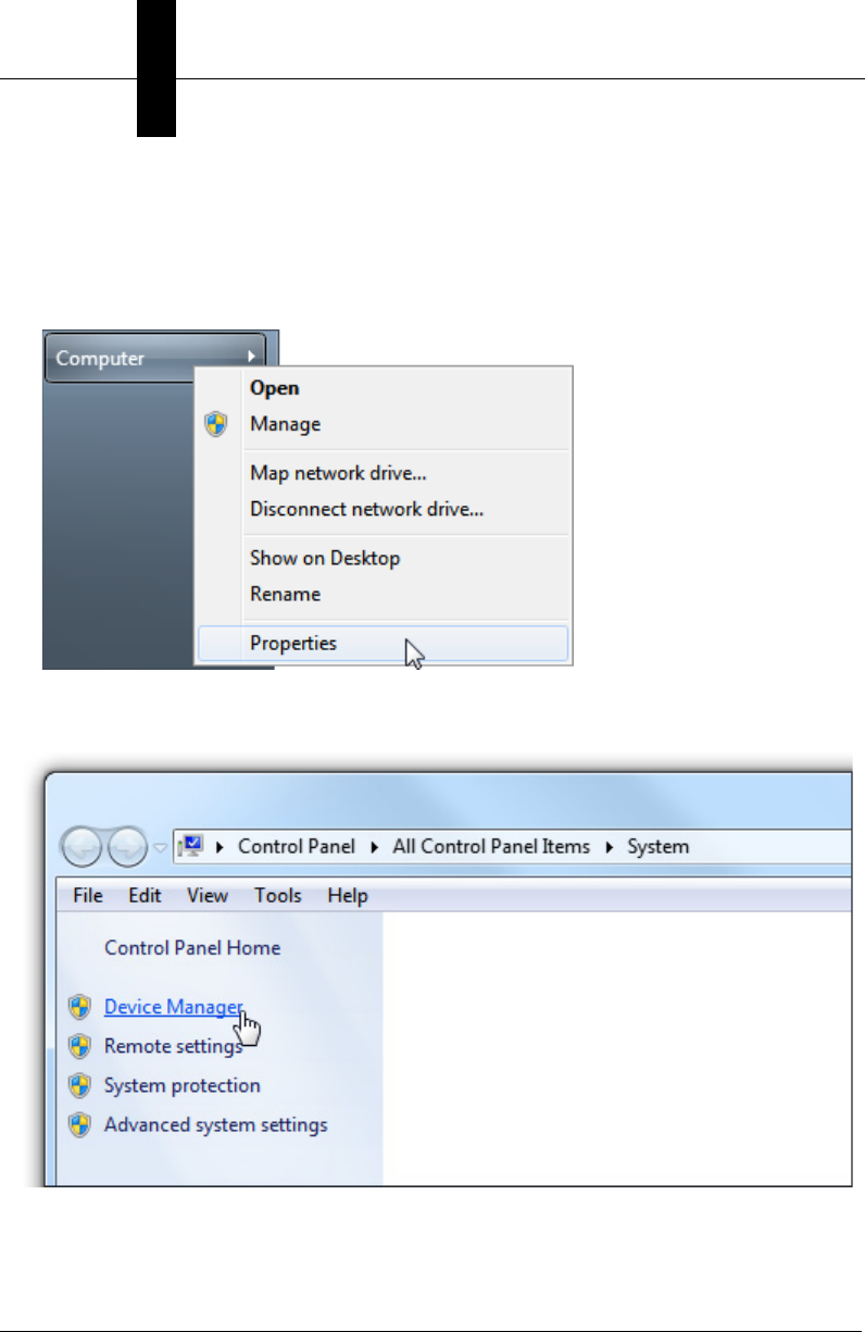
Appendix EUSB Power Management (MV-20 and MV-30)
E-2 MicroHAWK MV-20 / MV-30 / MV-40 Smart Camera Guide
USB Root Hub Power Management
Perform the following procedure to ensure that your PC does not shut down the USB
connection to your MicroHAWK MV-20, MV-30, or MV-40.
1. From the Windows Start menu, right-click on Computer and select Properties.
2. Select Device Manager from the options at the left side of the screen.
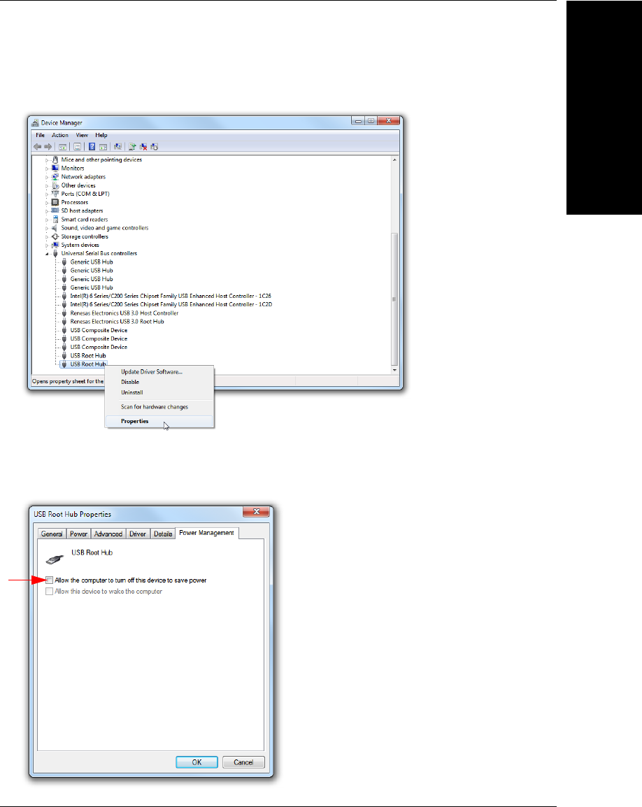
USB Power
Management
E
MicroHAWK MV-20 / MV-30 / MV-40 Smart Camera Guide E-3
3. In the Device Manager, locate and expand the Universal Serial Bus controllers
item. Right-click on USB Root Hub and select Properties.
4.
In the
USB Root Hub Properties
dialog, select the
Power Management
tab. Un-check
the box next to
Allow the computer to turn off this device to save power
. Repeat
steps
3
and
4
for each
USB Root Hub
item in the
Universal Serial Bus controllers
list.

Appendix EUSB Power Management (MV-20 and MV-30)
E-4 MicroHAWK MV-20 / MV-30 / MV-40 Smart Camera Guide

MicroHAWK MV-20 / MV-30 / MV-40 Smart Camera Guide F-1
F
TCP/UDP and General
Port Usage
F
APPENDIX F TCP/UDP and General Port
Usage
This section lists the ports used by MicroHAWK Smart Cameras
for communication.

Appendix FTCP/UDP and General Port Usage
F-2 MicroHAWK MV-20 / MV-30 / MV-40 Smart Camera Guide
MicroHAWK Ports
The following table lists the ports used by MicroHAWK Smart Cameras for communication.
Port Number Protocol Name
49059 TCP RPC
49049 TCP I/O
49050 TCP PIC/LIVE
49200 TCP REPORT
49202 TCP REPORTCONTROL
49201 TCP PARTQ
49079 TCP KEEPALIVE
49211 TCP Serial TCP#1
49212 TCP Serial TCP#2
49213 TCP Serial TCP#3
49214 TCP Serial TCP#4
49497 UDP UDP BROADCAST
49496 UDP UDP COMMAND
21 TCP FTP
23 TCP TELNET
80 TCP HTTP
