Getting Started With Your UID Compliance Verifier Uidverifiermanual
Uidverifiermanual uidverifiermanual uidverifiermanual 7d528818-df33-4025-8f65-74c5da0d78e5 _att microscan :
2009-05-25
: Microscan Uidverifiermanual uidverifiermanual 67f08bcc-a1a0-407c-9598-18a3752a134b _att
Open the PDF directly: View PDF ![]() .
.
Page Count: 148 [warning: Documents this large are best viewed by clicking the View PDF Link!]
- Getting Started With Your UID Compliance Verifier
- Contents
- CHAPTER 1 Getting Started w/UID Compliance Verifier
- Overview of UID Compliance Verifier, LDP (UID-LDP)
- Overview of UID Compliance Verifier, DPM (UID-DPM)
- Components — UID-LDP
- Components — UID-DPM
- UID-LDP & UID-DPM Operating Environment
- Choosing a PC
- Installing Optional Long Feet Spacers
- Powering Up the UID-LDP & UID-DPM
- Loading the Software
- Networking to the UID-LDP & UID-DPM
- Upgrading the UIDChecker™ Software from V2.1
- Lighting for the UID-LDP & UID-DPM
- CHAPTER 2 Quickly Using UID Compliance Verifier
- CHAPTER 3 UIDChecker™ Application Details
- File Naming Scheme
- Secured UID Verifier
- UIDChecker™ User Interface Overview
- UIDChecker™ Buttons Overview
- Main Menu Items
- File
- Reader
- Define Customer Fields
- Results Setup
- Automatically Save the Result with Each Read
- Store Images With Results
- Convert Image to JPG
- Show Verification Details in On-Screen Results View
- Show Decoded Data Above Image
- Store Results in MDB Database and CSV File
- Variance to Override Cell Size Restrictions
- Enable CPN/LBN Support
- Change Results Path
- Clear Log View
- Close
- View Results
- About
- UIDChecker™ UID Mark Validation Error Messages
- UIDChecker™ Data Matrix Verification Error Messages
- CHAPTER 4 UID Read Result Data Details
- APPENDIX A Upgrading to UIDChecker™ V2.1
- APPENDIX B Read And Rotate
- APPENDIX C Attaching UID-DPM to UID-DPM Stand
- APPENDIX D Upgrading UID-DPM001 w/UIDChecker Software V2.3
- Setting Up the UID-DPM Stand
- Attaching the Camera
- Assembling the Lights
- Preparing the Lenses
- Attaching the Lights to the Camera
- Recommended Verifier Setting with 25mm Lens
- Recommended Verifier Setting with 35mm Lens
- Setting Up the Network
- Upgrading the Software
- Configuring the Verifier
- HawkEye Sensor/Lighting Normalization
- Reflectance Calibration
- APPENDIX E Fixing ADO Components Error
- APPENDIX F Data File Formats for UIDChecker Software
- APPENDIX G Certification & Specifications
- Index

Getting Started With Your UID
Compliance Verifier
EM-40266-1V231
v2.3.1, Dec 2008
Copyright and Disclaimer
Copyright ©2008 by Microscan Systems, Inc.
1201 S.W. 7th Street, Renton, WA, U.S.A. 98057
(425) 226-5700 FAX: (425) 226-8682
All rights reserved. The information contained herein is proprietary and is provided solely for the purpose of allowing
customers to operate and/or service Microscan manufactured equipment and is not to be released, reproduced, or used
for any other purpose without written permission of Microscan.
Throughout this manual, trademarked names might be used. Rather than place a trademark (™) symbol at every
occurrence of a trademarked name, we state herein that we are using the names only in an editorial fashion, and to the
benefit of the trademark owner, with no intention of infringement.
Disclaimer
The information and specifications described in this manual are subject to change without notice.
Latest Manual Version
For the latest version of this manual, see the Download Center on our web site at: www.microscan.com.
Technical Support
For technical support, email: helpdesk@microscan.com.
Microscan Systems, Inc.
1201 S.W. 7th Street
Renton, WA 98057
U.S.A.
Tel: 425 226 5700
Fax: 425 226 8250
helpdesk@microscan.com
Microscan Europe
Tel: 31 172 423360
Fax: 31 172 423366
Microscan Asia Pacific
R.O. Tel: 65 6846 1214
Fax: 65 6846 4641
Microscan Limited Warranty Statement and Exclusions
What Is Covered?
Microscan Systems Inc. warrants to the original purchaser that products manufactured by it will be free from defects in
material and workmanship under normal use and service for a period of one year from the date of shipment. This
warranty is specifically limited to, at Microscan’s sole option, repair or replacement with a functionally equivalent unit
and return without charge for service or return freight.
What Is Excluded?
This limited warranty specifically excludes the following: (1) Any products or parts that have been subject to misuse,
neglect, accident, unauthorized repair, improper installation, or abnormal conditions or operations; (2) Any products or
parts that have been transferred by the original purchaser; (3) Customer mis-adjustment of settings contrary to the
procedure described in the Microscan Systems Inc. owners manual; (4) Upgrading software versions at customer request
unless required to meet specifications in effect at the time of purchase; (5) Units returned and found to have no failure
will be excluded; (6) Claims for damage in transit are to be directed to the freight carrier upon receipt. Any use of the
product is at purchaser’s own risk. This limited warranty is the only warranty provided by Microscan Systems Inc.
regarding the product. Except for the limited warranty above, the product is provided “as is.” To the maximum extent
permitted by law, this express warranty excludes all other warranties, express or implied, including but not limited to,
implied warranties of merchantability and. Technical support questions may be directed to: helpdesk@microscan.com
Register your product with Microscan: www.microscan.com/register fitness for a particular purpose. Microscan Systems
Inc. does not warrant that the functions contained in the product will meet any requirements or needs purchaser may
have, or that the product will operate error free, or in an uninterrupted fashion, or that any defects or errors in the product
will be corrected, or that the product is compatible with any particular machinery.
Limitation of Liability
In no event shall Microscan Systems Inc. be liable to you or any third party for any special, incidental, or consequential
damages (including, without limitation, indirect, special, punitive, or exemplary damages for loss of business, loss of
profits, business interruption, or loss of business information), whether in contract, tort, or otherwise, even if Microscan
Systems Inc. has been advised of the possibility of such damages. Microscan Systems Inc.’s aggregate liability with
respect to its obligations under this warranty or otherwise with respect to the product and documentation or otherwise
shall not exceed the amount paid by you for the product and documentation. Some jurisdictions do not allow the
exclusion or limitation of incidental or consequential damages or limitations on an implied warranty, so the above
limitation or exclusion may not apply to you. This warranty gives you specific legal rights, and you may also have other
rights which may vary from state to state.
Tel: 425.226.5700 | Fax: 425.226.8250 | helpdesk@microscan.com

v2.3.1, Dec 2008 Getting Started With Your UID Compliance Verifier v
Contents
PREFACE Welcome! xi
Purpose of This Manual xi
Product Specification xii
UID Standards Compatibility Chart xiii
UID Topics – Where to Learn More on the Web xiii
Manual Conventions xiv
CHAPTER 1 Getting Started w/UID Compliance Verifier 1-1
Overview of UID Compliance Verifier, LDP (UID-LDP) 1-2
Overview of UID Compliance Verifier, DPM (UID-DPM) 1-3
Portable Operation 1-5
Components — UID-LDP 1-6
Components — UID-DPM 1-6
UID-LDP & UID-DPM Operating Environment 1-7
Choosing a PC 1-7
Installing Optional Long Feet Spacers 1-7
Powering Up the UID-LDP & UID-DPM 1-9
Loading the Software 1-9
Networking to the UID-LDP & UID-DPM 1-10
DHCP and Static IP Addresses Explained 1-12
Upgrading the UIDChecker™ Software from V2.1 1-13

Contents
vi Getting Started With Your UID Compliance Verifier v2.3.1, Dec 2008
Lighting for the UID-LDP & UID-DPM 1-15
Light Configurations 1-16
Positioning Data Matrix Mark for Verification 1-17
Light Control 1-17
Triggers 1-18
CHAPTER 2 Quickly Using UID Compliance Verifier 2-1
Using Your UIDChecker™ Software 2-1
First Time Startup 2-1
Subsequent Startups 2-3
Testing the UID Compliance Verifier 2-3
Perform Reflectance Calibration 2-3
Test the Correct Calibration 2-5
Test the Correct Operation 2-8
CHAPTER 3 UIDChecker™ Application Details 3-1
File Naming Scheme 3-1
Secured UID Verifier 3-2
UIDChecker™ User Interface Overview 3-2
UID Read & Graphical Display Details 3-3
Image 3-3
Validation Text Result 3-3
Verification Text Result 3-4
UID Mark Read Result/Status 3-4
Light Indicators 3-4
Text Box for UII Only Validation 3-4
Text Box for CPN/LBN Only Validation 3-5
Text Box for Validating UII & CPN/LBN in a Single Symbol 3-6
UIDChecker™ Buttons Overview 3-7
Live Video 3-7
Read And Rotate 3-8
Read UID Mark 3-8
Analyzing the Results of UID Compliance Check 3-8
View Result 3-9
Print Result 3-9
Save Result 3-9

Contents
v2.3.1, Dec 2008 Getting Started With Your UID Compliance Verifier vii
Main Menu Items 3-10
File 3-10
Exit 3-10
Reader 3-10
Find a Reader 3-10
Turn Laser Off 3-13
Calibrate 3-13
Lighting & Exposure 3-16
Verification Type 3-18
Define Customer Fields 3-21
Results Setup 3-22
Automatically Save the Result with Each Read 3-23
Store Images With Results 3-23
Convert Image to JPG 3-23
Show Verification Details in On-Screen Results View 3-23
Show Decoded Data Above Image 3-23
Store Results in MDB Database and CSV File 3-23
Variance to Override Cell Size Restrictions 3-25
Enable CPN/LBN Support 3-26
Change Results Path 3-27
Clear Log View 3-27
Close 3-28
View Results 3-28
View Tab 3-30
Search Tab 3-32
Archive Tab 3-34
About 3-36
UIDChecker™ UID Mark Validation Error Messages 3-37
UIDChecker™ Data Matrix Verification Error Messages 3-39
CHAPTER 4 UID Read Result Data Details 4-1
Analyzing the Results of UIDChecker™ 4-1
UID Results Data File 4-6
Version 2.3 UIDDataLog_2.3.0.csv File Format 4-7
Version 2.3 DataBase Table Layout 4-7
Understanding UID Mark Quality 4-11
Data Matrix Cell Size 4-11
ECC 200 4-11
Data Matrix Quality Verification Standard 4-11

Contents
viii Getting Started With Your UID Compliance Verifier v2.3.1, Dec 2008
APPENDIX A Upgrading to UIDChecker™ V2.1 A-1
APPENDIX B Read And Rotate B-1
Read And Rotate Usage Details B-1
APPENDIX C Attaching UID-DPM to
UID-DPM Stand C-1
Setting Up the UID-DPM Stand C-1
Attaching the UID-DPM C-2
APPENDIX D Upgrading UID-DPM001 w/UIDChecker Software
V2.3 D-1
Setting Up the UID-DPM Stand D-2
Attaching the Camera D-2
Assembling the Lights D-3
Preparing the Lenses D-3
Attaching the Lights to the Camera D-4
Recommended Verifier Setting with 25mm Lens D-5
Recommended Verifier Setting with 35mm Lens D-7
Setting Up the Network D-9
Upgrading the Software D-9
Configuring the Verifier D-9
HawkEye Sensor/Lighting Normalization D-10
Reflectance Calibration D-12
APPENDIX E Fixing ADO Components Error E-1
APPENDIX F Data File Formats for UIDChecker Software F-1
Version 1.0 UIDDataLog.Dat File Format F-1
Version 2.0 UIDDataLog.Dat File Format F-4
Version 2.1 UIDDataLog.csv File Format F-10

Contents
v2.3.1, Dec 2008 Getting Started With Your UID Compliance Verifier ix
Version 2.1 DataBase Table Layout F-11
Version 2.2 DataBase Table Layout F-14
APPENDIX G Certification & Specifications G-1
CE Compliance G-1
FCC Statement G-2
FDA Statement G-2
Specifications G-3
UID-LDP G-3
Physical Characteristics G-3
Performance Characteristics G-3
User Environment G-3
UID-DPM G-4
Physical Characteristics G-4
Performance Characteristics G-4
User Environment G-4
Index Index-1

Contents
xGetting Started With Your UID Compliance Verifier v2.3.1, Dec 2008

v2.3.1, Dec 2008 Getting Started With Your UID Compliance Verifier xi
Preface
PREFACE Welcome!
Purpose of This Manual
The purpose of this manual is to get you up and running with your UID
Compliance Verifier quickly and confidently. The manual covers the following
two products:
• UID Compliance Verifier, LDP, for labels and data plates (UID-LDP)
• UID Compliance Verifier, DPM, for direct part marks (UID-DPM)
Preface
xii Getting Started With Your UID Compliance Verifier v2.3.1, Dec 2008
Product Specification
The following table is a product specification of the UID Compliance Verifier.
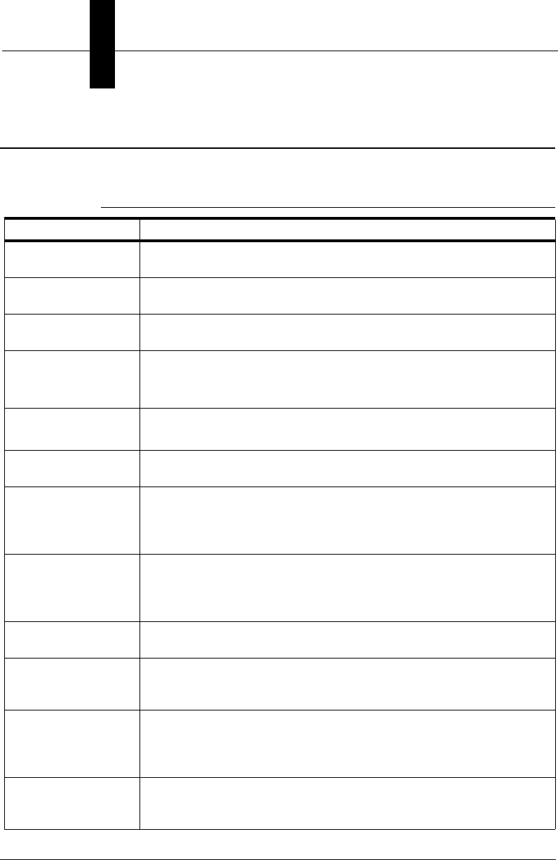
TABLE 1. Product Specification
Item Description as Implemented
Hardware HE1525HDU for UID-LDP, HE1510 for UID-DPM; Customer’s Windows
2000, Windows XP, or Windows Vista Business PC
Target Reading, verifying and validating Unique Identification (UID) marks. UID
Marks are Data Matrix Codes
Symbology Type The UID Compliance Verifier verifies the Data Matrix Symbology type
ECC 200
Measuring apertures
or effective
resolution available
Aperture 05 is used for MIL-STD-130L and MIL-STD-130M
Aperture is determined by the AIM DPM verification algorithm in
MIL-STD-130M/Change 1 and MIL-STD-130N
Overall Sizes of
Symbols UID-LDP:0.075” - 0.6”
UID-DPM:0.075” - 0.8”
Specification of
illumination source 640 +/- 20 nm
Means of
Reflectance
calibration
Two calibration points are used. A calibration sample with NIST
traceable 80% contrast calibrates the high reflectance end of the range.
The sensor’s black level is calibrated to be the low reflectance of the
range.
Means of Reporting
and recording
verification results
A comma-delimited file contains the record data; HTML files contain the
verification results including images; on screen results reported real-
time. An Access database stores information in a format that can be
queried.
Optional Functions
performed Ability to add a customer’s graphics to the reports.
Ability to average
results from repeated
scans
The UID Compliance Verifier averages five scans in different
orientations per MIL-STD-130L (ISO/IEC 15415) when selected.
Interfacing
capabilities The verification results are reported to the PC as html files, which can
be viewed using Internet Explorer. UIDChecker™ supports data
logging, archival and printing. Reports can be created by querying the
results database.
Programming and
Configuration The UID Compliance Verifier is programmed upon hardware startup to
default settings via the PC over ethernet. UIDChecker™ supports data
logging, archival and printing
v2.3.1, Dec 2008 Getting Started With Your UID Compliance Verifier xiii
UID Standards Compatibility Chart
This version of UIDChecker™ software is compliant with the following:
UID Topics – Where to Learn More on the Web
• UID Support Site: http://www.uidsupport.com
From this site, you can find links to:
– Department of Defense Guide
– MIL-STD-130N
– NASA Handbook on Marking Standards
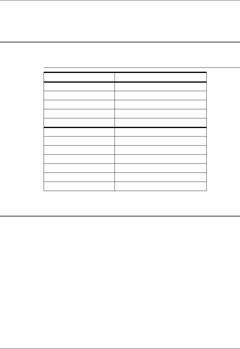
TABLE 2. UID Compatibility Chart
Standard Release Date
DFARS 252.211-7003 April 22, 2005
ISO/IEC 15415 June 15, 2004
ISO/IEC 15418 December 1, 1999
ISO/IEC 15434 October 1, 1999
ISO/IEC 16022 May 1, 2000
MIL-STD-130L Pre- and Post- December 20, 2004
MIL-STD-130L, Change 1 December 21, 2004
MIL-STD-130M December 2, 2005
SAE AS9132 February 15, 2005
AIM DPM-1-2006 December 12, 2006
MIL-STD-130M Change 1 June 15, 2007
MIL-STD-130N December 17, 2007
Preface
xiv Getting Started With Your UID Compliance Verifier v2.3.1, Dec 2008
Manual Conventions
The following typographical conventions are used throughout this manual.
• Items emphasizing important information is bolded.
• Menu selections, menu items and entries in screen images are indicated as:
Run (triggered), Modify..., etc.
Indicates Class II laser radiation.

v2.3.1, Dec 2008 Getting Started With Your UID Compliance Verifier 1-1
1
Getting Started w/UID
Compliance Verifier
1
CHAPTER 1 Getting Started w/UID
Compliance Verifier
This guide provides information you need to quickly set up and use the following
Microscan UID Compliance Verifier products:
• UID Compliance Verifier, LDP, for labels and data plates
• UID Compliance Verifier, DPM, for direct part marks
Full product details can be found in the latter chapters of this manual.
Chapter 1Getting Started w/UID Compliance Verifier
1-2 Getting Started With Your UID Compliance Verifier v2.3.1, Dec 2008
Overview of UID Compliance Verifier, LDP (UID-LDP)
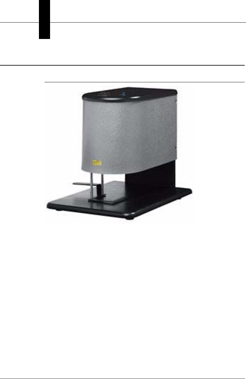
FIGURE 1–1. UID-LDP
The UID Compliance Verifier, LDP (UID-LDP) is designed for labels and data
plates containing UID Data Matrix marks with thicknesses up to 1/8 inches (3.2
mm). The Diffuse Perpendicular (90) lighting allows the bottom of the light to be
more than 1.5 inches from the mark for ease of use. The laser targeting aids in
placing the mark in the center of the camera’s field of view (FOV). The FOV is
1.0 inches x 0.75 inches (25.4 mm x 19.0 mm). The maximum supported Data
Matrix size is 0.6 inches (15 mm). This size allows either a Data Matrix of:
• 24-row by 24-column using X dimension of 25 mil
(0.025 inches) element size
• Higher density using X dimension of 7.5 mil
(0.0075 inches) element size
Overview of UID Compliance Verifier, DPM (UID-DPM)
Getting Started w/UID
Compliance Verifier
1
v2.3.1, Dec 2008 Getting Started With Your UID Compliance Verifier 1-3
Overview of UID Compliance Verifier, DPM (UID-DPM)
FIGURE 1–2. UID-DPM for Label and Data Plate
The UID Compliance Verifier, DPM, (UID-DPM) is designed for UID Data
Matrix direct part marks with varying thicknesses and shapes. It provides all the
lighting options specified in AIM DPM-1-2006:
• Medium Angle Four Direction (45Q)
• Low Angle Four Direction (30Q)
• Low Angle Two Direction (30T)
• Low Angle Single Direction (30S)
• Diffuse Perpendicular (90)
• Diffuse Off Axis (D)
The FOV is 1.19 inches x 0.86 inches (30.2 mm x 21.8 mm). The maximum Data
Matrix size that can be supported is 0.8 inches (20 mm). This size allows a 32-
row by 32-column Data Matrix using X dimension of 25 mil (0.025 inches) or a
Data Matrix of higher density with X dimension as small as .75 mil (0.0075
inches).
Chapter 1Getting Started w/UID Compliance Verifier
1-4 Getting Started With Your UID Compliance Verifier v2.3.1, Dec 2008
To read Data Matrix labels and data plates up to 1/8 inches (3.2mm), the
UID-DPM can be placed on the four standard feet that measure 0.875 inches
(22 mm) long.
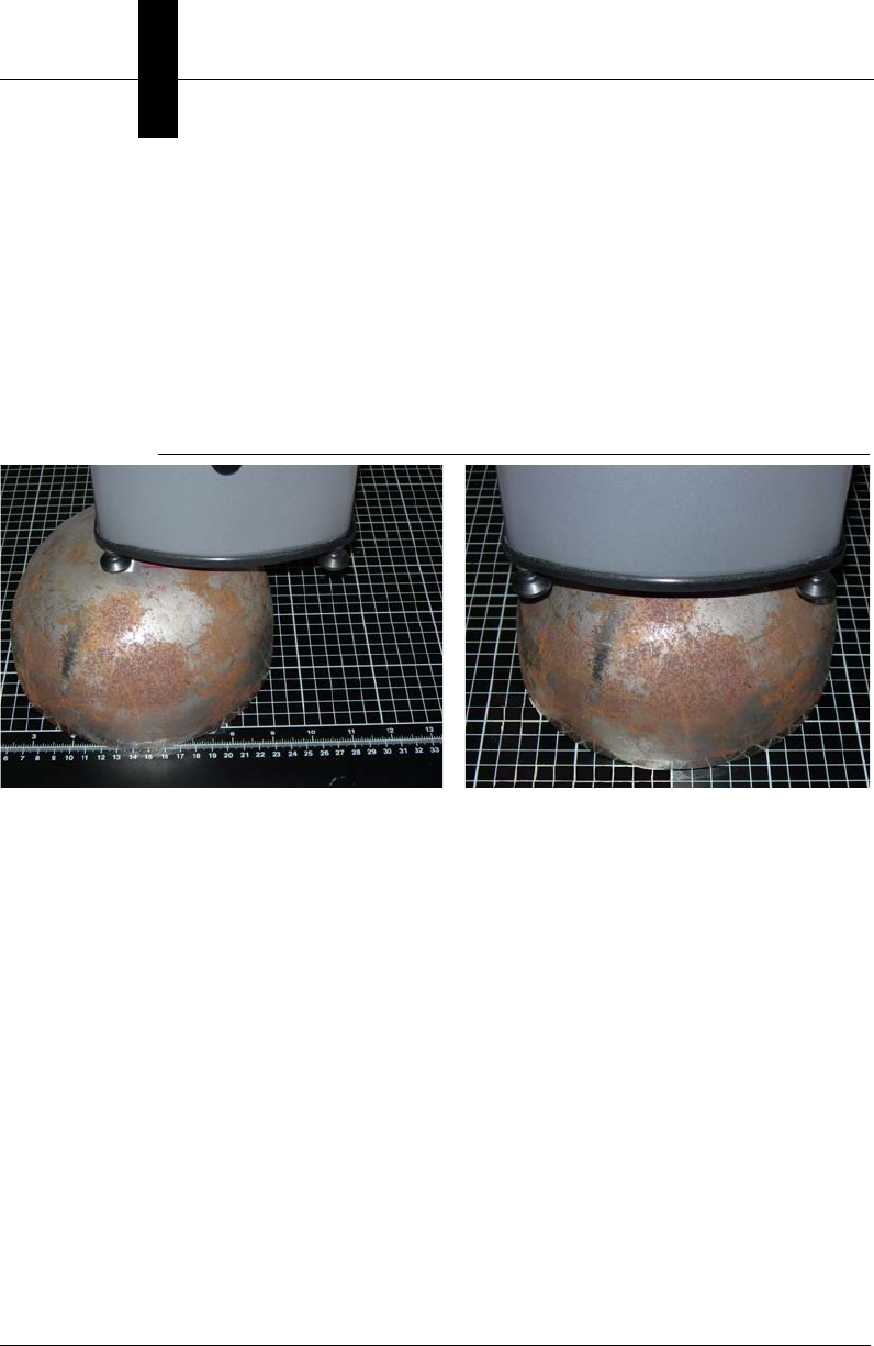
The UID-DPM can be mounted on the UID Verifier stand (see Appendix C,
“Attaching UID-DPM to UID-DPM Stand,”) for reading Data Matrix labels, data
plate, and DPM. The surface of the Data Matrix must be at the correct distance
measurable using one of the standard feet.
FIGURE 1–3. UID-DPM for Verifying DPM
Measuring Distance Using Foot Verifying
Overview of UID Compliance Verifier, DPM (UID-DPM)
Getting Started w/UID
Compliance Verifier
1
v2.3.1, Dec 2008 Getting Started With Your UID Compliance Verifier 1-5
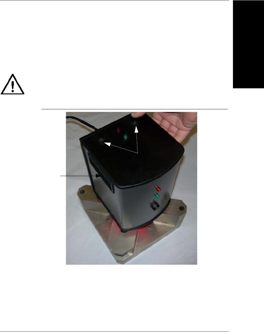
Portable Operation
The UID-DPM supports limited portable operation using the standard feet.
Simply hold it against a large flat part and press any one of the three trigger
buttons, as shown in Figure 1–4.
FIGURE 1–4. UID-DPM for Portable Operation
Caution
Please be very careful when using the unit in this manner, and avoid dropping it.
Buttons
Handle
(1 of 2)

Chapter 1Getting Started w/UID Compliance Verifier
1-6 Getting Started With Your UID Compliance Verifier v2.3.1, Dec 2008
Components — UID-LDP
• UID-LDP Bench Top Verifier (FIS-UD20-0CK1)
• UID-LDP Power Supply (933-0113-1)
• Ethernet network cable (HEENET-007)
• UID Compliance Card to test your UID-LDP (A4-20814-1A)
• UIDChecker™ Software Installation CD (A1-40266-1V230)
• Calibration Test Card (98-UA10-0CC0)
• Ethernet Cross Link Adapter (HEENET-XLA)
• Serial Communications Cable (HESC-006) {Hardware rescue aid only}
• This Getting Started guide
Components — UID-DPM
• UID-DPM Verifier with Multifunction Light (FIS-UD10-0DP1)
• UID-DPM Standard Presentation Feet
• UID-DPM Optional Long Feet Spacers
• UID-DPM Power Supply (A1-40346-1)
• Ethernet network cable (HEENET-007)
• UID Compliance Card to test your UID-DPM (A4-20814-1A)
• UIDChecker™ Software Installation CD (A1-40266-1V230)
• Calibration Card (98-UA10-0CC0)
• Ethernet Cross Link Adapter (HEENET-XLA)
• Serial Communications Cable (HESC-006) {Hardware rescue aid only}
• This Getting Started guide

UID-LDP & UID-DPM Operating Environment
Getting Started w/UID
Compliance Verifier
1
v2.3.1, Dec 2008 Getting Started With Your UID Compliance Verifier 1-7
UID-LDP & UID-DPM Operating Environment
• Operating Temperature: 32°F to 104°F (0°C to 40°C)
• Storage Temperature: 122°F (50°C) Max
Choosing a PC
The UID-LDP and UID-DPM systems require you to supply a PC running
Microsoft Windows 2000, Windows XP, or Windows Vista Business with:
• Administrator privileges
• At least a 2 GHz CPU
• At least 512M RAM
• A CD-ROM drive
• At least 100 Mb of available hard disk space
• A 10/100 Mb Network (Ethernet) Interface
• Display capable of displaying at least 1024 by 768 pixels, true colors
Note: In some installations, you will need two network ports: one for your PC
and one for the UID-LDP or UID-DPM. For more information, see “Networking
to the UID-LDP & UID-DPM” on page 1-10.
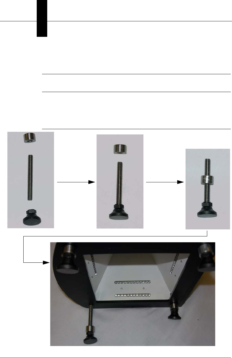
Installing Optional Long Feet Spacers
For UID-DPM, the feet with standard spacers are installed at the factory to
provide the normal stand-off distance of 7/8 inch (22.2 mm). You can lengthen
the feet using the optional spacers.
• For labels and data plates with thicknesses up to 1/8 inches (3.2 mm), use the
standard spacers.
• For DPM parts with thicknesses up to 5/8 inches (15.9 mm), replace the
standard spacers with the optional long spacers.
Chapter 1Getting Started w/UID Compliance Verifier
1-8 Getting Started With Your UID Compliance Verifier v2.3.1, Dec 2008
• For DPM parts with thicknesses up to 15/16 inches (23.8 mm), add the
optional long spacers to the standard spacers.
Note: You need to make sure that the mark surface of the DPM part is
approximately 7/8 inches (22.2 mm) from the bottom of the plate.
To install the optional long feet spacer, or to re-install the standard feet, follow
Figure 1–5.
FIGURE 1–5. Installing the Feet on the UID-DPM (Standard Spacers Shown)
Powering Up the UID-LDP & UID-DPM
Getting Started w/UID
Compliance Verifier
1
v2.3.1, Dec 2008 Getting Started With Your UID Compliance Verifier 1-9
Powering Up the UID-LDP & UID-DPM
1. Connect the power supply to the UID-LDP or UID-DPM, then plug the
power supply into a 120V to 230V outlet.
2. Connect the UID-LDP or UID-DPM to your Ethernet network. See
“Networking to the UID-LDP & UID-DPM” on page 1-10 for details.
Note: There may be a delay of up to 25 seconds while the verifier sets up to
use the default DHCP settings.
Loading the Software
Note: To install the UIDChecker™ software, you must be logged on with
Administrator privileges. Contact your IT department for help getting
Administrator privileges. You do not need to have Administrator privileges to run
the UIDChecker™.
Note: You must remove older versions of the software before upgrading. If beta
versions of this version software have been installed, the results directory must
be moved, renamed, or deleted, as earlier database records are incompatible with
the released version.
Use the following procedure to install the UIDChecker™ software:
1. Insert the UIDChecker™ Software CD into the CD-ROM drive. In a few
moments, the UIDChecker™ software will automatically start the
installation program. If this fails, select the CD-ROM drive in Windows
Explorer and run the Setup.exe program.
2. The installation program installs the UIDChecker™ application and the
HawkEye 1500 Smart Camera firmware. (You will need to install the
firmware to the HawkEye 1500 camera if you are upgrading your UID
Compliance verifier). When the Install program is finished, you may have to
reboot your PC. Just follow the on-screen instructions.
Chapter 1Getting Started w/UID Compliance Verifier
1-10 Getting Started With Your UID Compliance Verifier v2.3.1, Dec 2008
By default, the installation of the UIDChecker™ application installs all the
necessary components in the C:\Program Files\UIDChecker folder. The folder
will be created if it doesn’t already exist. You can change the location of the file
at installation. All subsequent files, data and images, are located under the main
UIDChecker folder on the customer’s hard drive.
Networking to the UID-LDP & UID-DPM
The UID-LDP and UID-DPM communicate to the PC using an Ethernet network.
There are several ways to connect the UID-LDP/UID-DPM and the PC.
Note: This is often the trickiest part of the installation, especially if you are not
familiar with Ethernet and connecting equipment to your network. If this is the
case, please contact your IT department for help or contact Microscan.
1. The easiest way to connect your PC and the UID-LDP or UID-DPM is to
connect them to an existing local area network (LAN) using the Ethernet
cable that is already attached to the verifier. To do this, plug your PC into
your LAN, and plug your verifier into your LAN (you will need two
Ethernet ports).
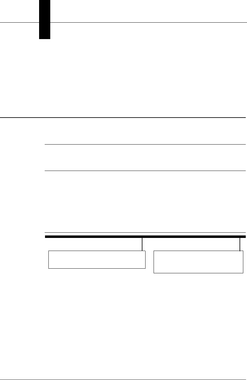
FIGURE 1–6. PC & UID-LDP/UID-DPM on Your Ethernet Network
Your PC - Connect to an Ethernet
Your Ethernet Network
port on your Ethernet network UID Verifier - Connect to
a second Ethernet port on
your Ethernet network
Networking to the UID-LDP & UID-DPM
Getting Started w/UID
Compliance Verifier
1
v2.3.1, Dec 2008 Getting Started With Your UID Compliance Verifier 1-11
2. The second way to connect your PC and the UID-LDP/UID-DPM is to
connect them to each other using an Ethernet hub, switch or router (not
supplied). You may need your IT department to help you select hardware
and set this up.
FIGURE 1–7. Connection Using a Hub, Router or Switch
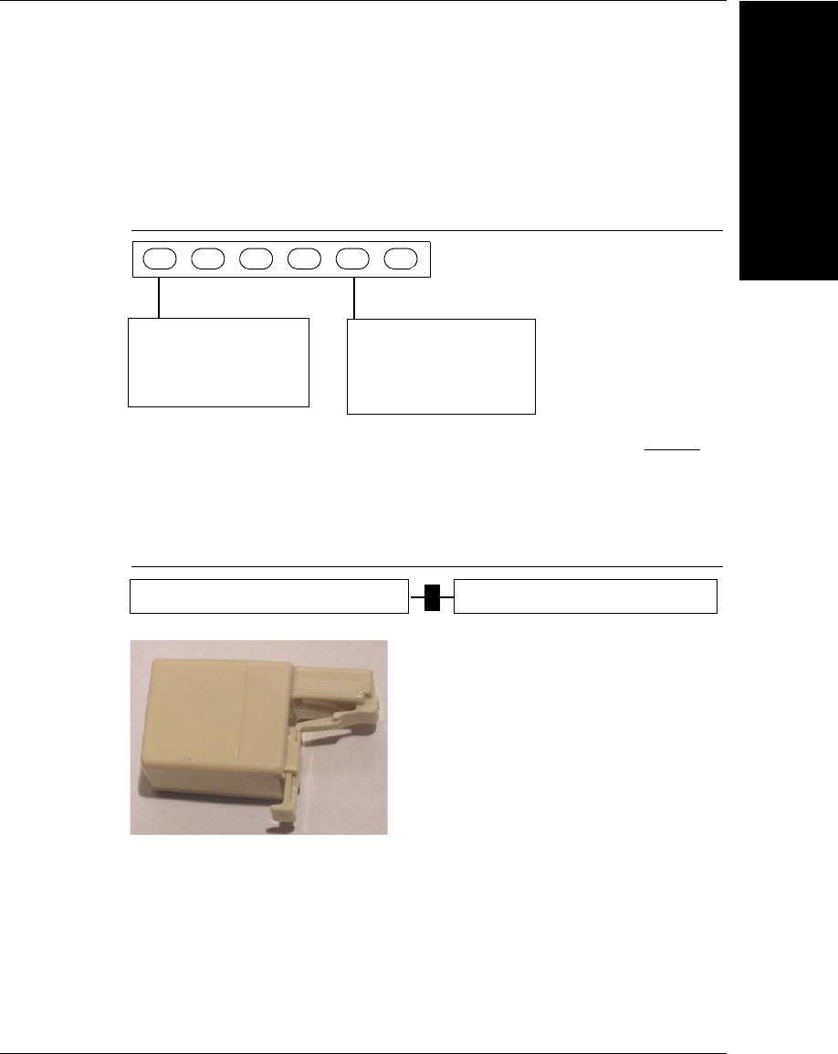
3. The final way to connect the PC and the reader is to connect them directly to
each other on their own private LAN. Do this by adding the supplied
cross-link adapter to the reader’s Ethernet cable and plugging it directly into
the PC’s network card.
FIGURE 1–8. Direct Connect PC & UID-LDP/UID-DPM using Cross-Link Adapter
Your PC - Connect
Hub, Router, or Switch
via a hub, router
or switch to your
to your network
Connect via a hub
router or switch
to your network
UID Verifier -
Your PC - Connect to the UID Verifier UID Verifier - Connect to your PC
Cross-Link Adapter (HEENET-XLA)
Chapter 1Getting Started w/UID Compliance Verifier
1-12 Getting Started With Your UID Compliance Verifier v2.3.1, Dec 2008
DHCP and Static IP Addresses Explained
Note: If this is confusing or if you do not understand the terminology, contact
your IT department for help.
At the Microscan factory, the UID-LDP and UID-DPM are set to use Dynamic
Host Communication Protocol (DHCP). In most cases, this means you simply
have to plug the UID-LDP/UID-DPM into your network and plug your PC into
your network, and the UIDChecker™ software will just find the verifier and
work. This works because your network is set up to automatically assign IP
addresses to the computers on the network.
If there is no automatic assignment of IP addresses (no DHCP), then the PC’s IP
address must be set to communicate with the address of the verifier. To do this,
you must have Administrator privileges on the PC, and must do the following:
1. Right click on Network Places and select Properties.
2. Right click on your Network Card and select Properties.
3. Scroll down in the Connection Components list.
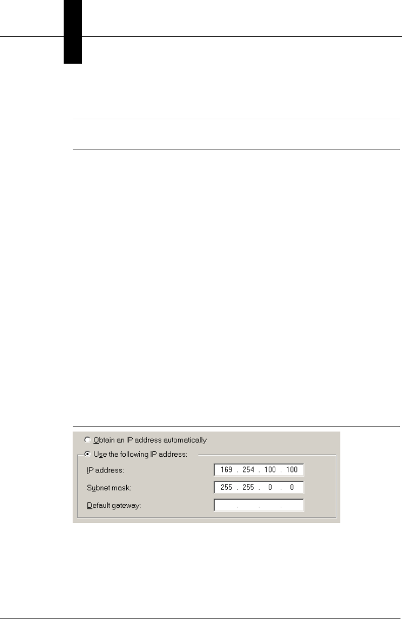
4. Select the Internet Protocol item - and select Properties.
5. Select “Use the following IP address” and enter address 169.254.100.100
and mask 255.255.0.0, as shown in Figure 1–9.
FIGURE 1–9. Entering IP Address and Subnet Mask
6. Click OK.

Upgrading the UIDChecker™ Software from V2.1
Getting Started w/UID
Compliance Verifier
1
v2.3.1, Dec 2008 Getting Started With Your UID Compliance Verifier 1-13
Upgrading the UIDChecker™ Software from V2.1
To upgrade an existing UID-CK reader running UIDChecker™ V2.1 or earlier to
use the new verification type AIM DPM-1-2006 supported in V2.3, you will
need to upgrade the hardware first before upgrading the software.
To upgrade an existing UID-DPM001 running UIDChecker™ V2.1 or earlier to
use the new verification type AIM DPM-1-2006 supported in V2.3, we
recommend that you upgrade the hardware first before upgrading the software. If
you want to use your existing hardware, you can upgrade only the software (see
Appendix D, “Upgrading UID-DPM001 w/UIDChecker Software V2.3,” for
more information).
If your UIDChecker™ version is older than V2.1, first follow Appendix A,
“Upgrading to UIDChecker™ V2.1,” to upgrade your system to running
UIDChecker™ V2.1. Then, install the UIDChecker™ V2.3 software as follows:
Put the software installation disk into your PC’s CD drive and run Setup. The
automated program will prompt you to:
1. Uninstall the older version of UIDChecker™ software. Just follow the
prompts and click OK.
Note: It will not delete your results!
2. Uninstall the older version of HawkEye’s ReadRunner; this is no longer
needed in UIDChecker V2.3. Again, just follow the prompts and click OK.
3. Install the UIDChecker™ software. Just follow the prompts and click OK.
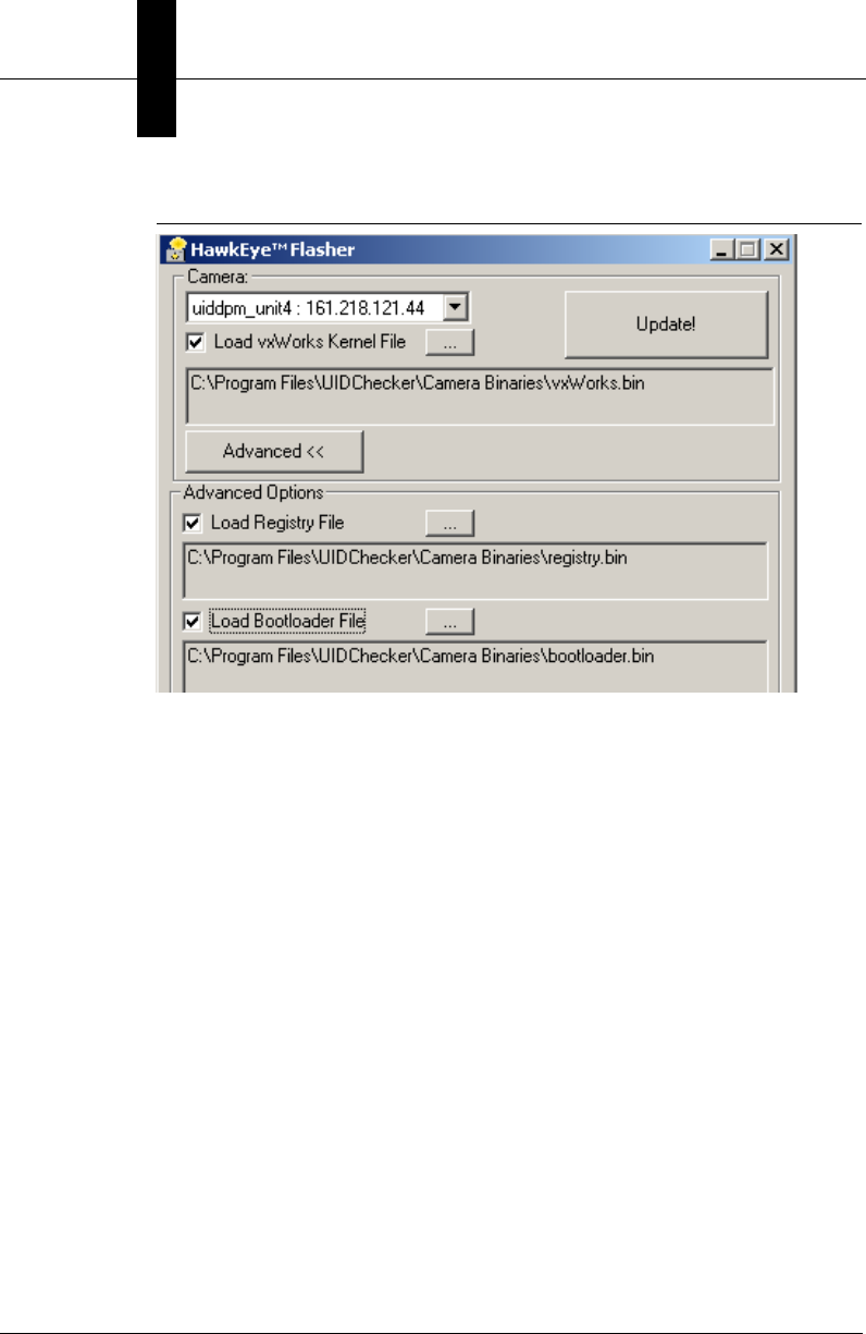
Before using the UIDChecker™ software, you need to upgrade the firmware on
the UID reader unit:
1. From the Start Menu, select Programs > UIDChecker > Utilities >
Hawkeye Flasher.
The HawkEye Flasher dialog box is displayed, as shown in Figure 1–10.
Chapter 1Getting Started w/UID Compliance Verifier
1-14 Getting Started With Your UID Compliance Verifier v2.3.1, Dec 2008
FIGURE 1–10. Upgrade the HawkEye™ Flasher Dialog Box
2. In the Camera drop down list, select your UID Verifier and make sure you
enable (check) all the check boxes for:
– Load VxWorks Kernel
– Load Registry File
– Load Bootloader.
3. Click Update!
When “Done” appears at the bottom of the terminal display, the process is
complete and you can now start the UIDChecker™ software.
Lighting for the UID-LDP & UID-DPM
Getting Started w/UID
Compliance Verifier
1
v2.3.1, Dec 2008 Getting Started With Your UID Compliance Verifier 1-15
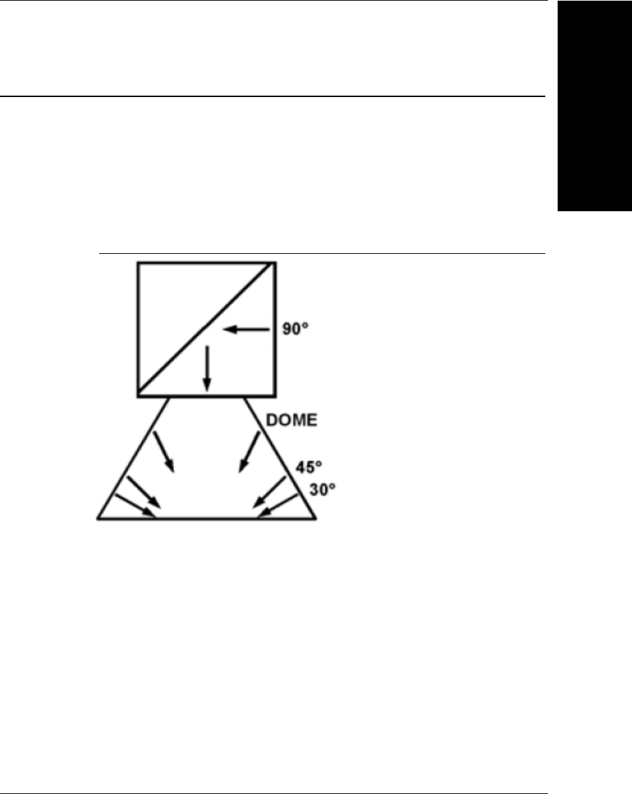
Lighting for the UID-LDP & UID-DPM
Both the UID-LDP and UID-DPM support AIM DPM-1-2006 fully compliant
lighting options. The UID-LDP uses the diffuse perpendicular lighting (90) for
label and data plate applications. The UID-DPM uses the multifunction light that
supports all light configurations required by MIL-STD-130M/Change 1 and
MIL-STD-130N, as shown in Figure 1–11. In both UID-LDP and UID-DPM, the
verification can be triggered from a hardware trigger button and the Read UID
Mark software button on the UIDChecker™ GUI.
FIGURE 1–11. Multifunction Light
For all verification types except AIM-DPM-1-2006, only diffuse perpendicular
lighting (90) is supported in UID-DPM.

Chapter 1Getting Started w/UID Compliance Verifier
1-16 Getting Started With Your UID Compliance Verifier v2.3.1, Dec 2008
Light Configurations
The multifunction light in UID-DPM supports all the light configurations
specified in the AIM DPM-1-2006:
• Diffuse perpendicular (on-axis/bright field) (90) — A flat diffusing material
is oriented such that the plane of the material is parallel to the plane of the
symbol area. The symbol is uniformly illuminated with diffuse light incident
at 90 ±15° relative to the optical axis to the plane of the symbol.
• Diffuse off-axis (D) — A diffusely reflecting dome is illuminated from
below so that the reflected light falls non-directionally on the part and does
not cast defined shadows. This is commonly used for reading curved parts.
• Low angle, four direction (30Q) — Light is aimed at the part at an angle of
30 ±3° from the plane of the surface of the symbol from four sides such that
the lines describing the center of the beams from opposing pairs of lights are
co-planar and the planes at right angles to each other. One lighting plane is
aligned to be parallel to the line formed by a horizontal edge of the image
sensor to within ±5°. The lighting illuminates the entire symbol area with
uniform energy.
• Low angle, two direction (30T) — Light is aimed at the part at an angle of
30 ±3° from two sides. The light may be incident from either of the two
possible orientations with respect to the symbol. The lighting plane is
aligned to be parallel to the line formed by one edge of the image sensor to
within ±5°. The lighting illuminates the entire symbol area with uniform
energy.
90° (+/-15)
30° (+/-3) from all 4 sides (North, East, South, West)
30° (+/-3) from 2 sides (North/South or East/West)

Lighting for the UID-LDP & UID-DPM
Getting Started w/UID
Compliance Verifier
1
v2.3.1, Dec 2008 Getting Started With Your UID Compliance Verifier 1-17
• Low angle, one direction (30S) — Light is aimed at the part at an angle of 30
±3° from one side. The light may be incident from any of the four possible
orientations. The lighting plane is aligned to be parallel to the line formed by
one edge of the image sensor to within ±5°. The lighting illuminates the
entire symbol area with uniform energy.
• Medium angle, four direction (45Q) — Light is aimed at the part at an angle
of 45 ±3° from the plane of the surface of the symbol from four sides such
that the lines describing the center of the beams from opposing pairs of lights
are co-planar and the planes at right angles to each other. One lighting plane
is aligned to be parallel to the line formed by a horizontal edge of the image
sensor to within ±5°. The lighting illuminates the entire symbol area with
uniform energy.
Positioning Data Matrix Mark for Verification
Always ensure the bottom plane of the light in UID-LDP and UID-DPM is
parallel to the plane of the Data Matrix symbol area.
Use Live Video to ensure the Data Matrix mark is centered in the FOV with the
correct orientation.
Light Control
The light in UID-LDP and UID-DPM will be switched on when the
UIDChecker™ program starts up and switched off when the program exits. The
state of the multifunction light is saved so that the program, when restarted, will
use the same light configuration as in the previous operation. The default light
configuration is 90 for the UID-DPM.
30° (+/-3) from 1 side (North, East, South, West)
45° (+/-3) from all 4 sides (North, East, South, West)

Chapter 1Getting Started w/UID Compliance Verifier
1-18 Getting Started With Your UID Compliance Verifier v2.3.1, Dec 2008
Triggers
In UID-LDP and UID-DPM, the verification can be triggered from:
• A hardware trigger button
• The Read UID Mark software button on the UIDChecker™ GUI
Note: The hardware trigger is disabled for the verification type MIL-STD-130L
Change 1 (ISO 15415) in order to support Read and Rotate. See Appendix B,
“Read And Rotate,” for details.
v2.3.1, Dec 2008 Getting Started With Your UID Compliance Verifier 2-1
2
Quickly Using UID
Compliance Verifier
2
CHAPTER 2 Quickly Using UID
Compliance Verifier
After loading the UIDChecker™ application software on your PC and powering
up the UID Compliance Verifier, you are now ready to begin using your UID
Compliance Verifier to read UID marks.
Using Your UIDChecker™ Software
To launch the UIDChecker™ application, select and click on the UIDChecker™
desktop icon, as shown in Figure 2–1.
FIGURE 2–1. UIDChecker™ Icon
First Time Startup
The first time you launch the application, the UIDChecker software will prompt
you for a Reader on the network to connect to. After that, it will attempt to re-
connect to the last reader each time it is launched, as shown in Figure 2–2.
Chapter 2Quickly Using UID Compliance Verifier
2-2 Getting Started With Your UID Compliance Verifier v2.3.1, Dec 2008
FIGURE 2–2. Find a Reader Menu Item
This option displays a list of readers on your network. If you have been
successful in setting up the network connection to the camera, you will find the
reader on the list. The name should begin with “UID”. Select your reader from
the drop down list.
Note: On some networks, there may be a delay of several minutes when you
power on and plug the Ethernet cable into your network. If no readers show up in
the drop down list (see Figure 2–3), then close the UIDChecker™ software, wait
five minutes, and launch the program again.
FIGURE 2–3. Drop Down List of Readers
Testing the UID Compliance Verifier
Quickly Using UID
Compliance Verifier
2
v2.3.1, Dec 2008 Getting Started With Your UID Compliance Verifier 2-3
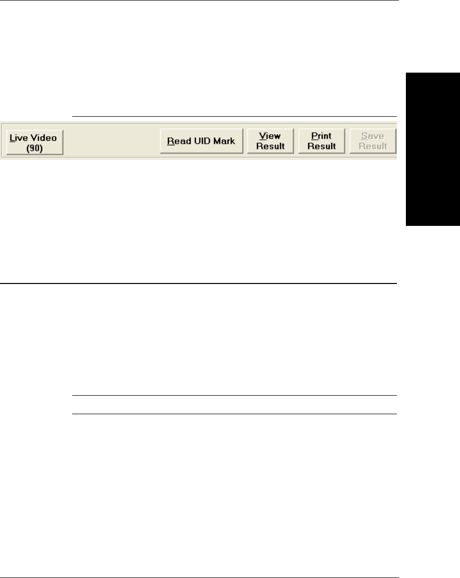
Once this has been done, the system will remember the reader and will connect to
it automatically. The command buttons will become active, as shown in
Figure 2–4:
FIGURE 2–4. Command Buttons Active
Subsequent Startups
As stated above, upon first-time startup, the UIDChecker will prompt for a reader
on the network to connect to. Upon subsequent restarts of UIDChecker™, the
UIDChecker™ will remember its reader and automatically select it, and the UID
Verifier will be ready to run.
Testing the UID Compliance Verifier
After completing all the hardware setup and software loading, you will want to
perform a quick check to ensure that your UID-LDP or UID-DPM verifier is
working properly. You will need the Microscan Calibration Test Card (Microscan
part number 98-UA10-0CC0) and the UID Compliance Card (Microscan part
number A4-20814-1A) to test your UID-LDP or UID-DPM.
Perform Reflectance Calibration
Note: Please refer to Reflectance Calibration in Chapter 3 for more detail.
Once you have positioned your UID-LDP or UID-DPM into your work space,
you need to calibrate the system using this Calibration Target.
1. Ensure UIDChecker™ has connected to your verifier. If you have never
calibrated the verifier from the UIDChecker™, you will see that Last
Calibrated: UNKNOWN displayed in Figure 2–5:

Chapter 2Quickly Using UID Compliance Verifier
2-4 Getting Started With Your UID Compliance Verifier v2.3.1, Dec 2008
FIGURE 2–5. Last Calibrated: UNKNOWN
2. The Reflectance Calibration box should be displayed automatically. If it is
not, click Reader > Reflectance Calibrate to bring up the Calibration
dialog box, as shown in Figure 2–6.
FIGURE 2–6. Reflectance Calibration Dialog Box
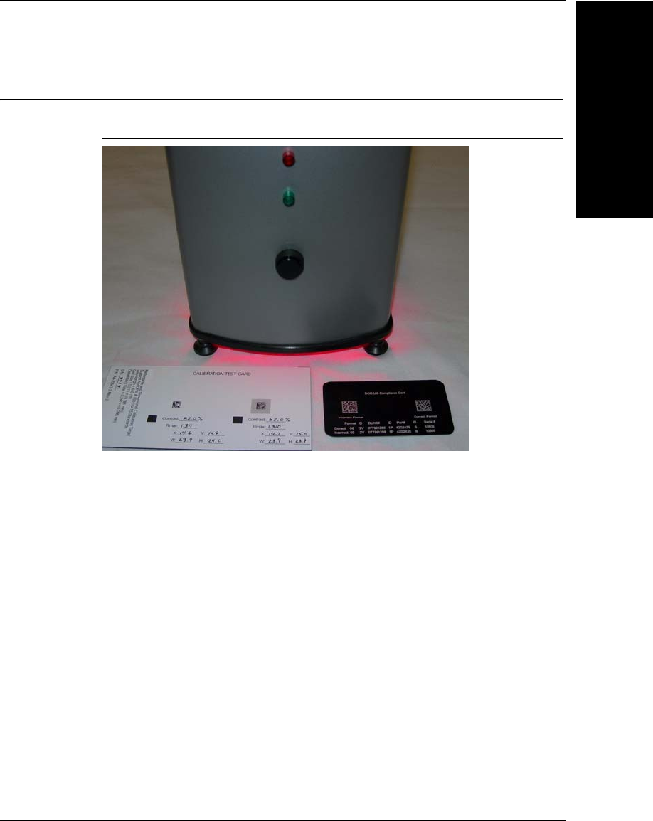
3. In the Calibration Target Contrast text box (see Figure 2–6), enter the
Contrast value shown on the card associated with the Data Matrix (80%
contrast) you are using as the target. For example, if the contrast marked for
the Data Matrix on the Calibration Test Card is 82.6%, you would enter 82.6
or 83.
4. In the Calibration Target Reflectance Max text box (see Figure 2–6), enter
the Rmax value shown on the card associated with the Data Matrix (80%
contrast) you are using as the target. For example, if the R_max marked for
the Data Matrix on the Calibration Test Card is 87.4%, you would enter 87.4
or 87.
Live Video mode is enabled.
5. Position the Data Matrix (around 80% contrast) under the UID-LDP or UID-
DPM. Center the Data Matrix in the camera's FOV, as shown in Figure 2–7.
Testing the UID Compliance Verifier
Quickly Using UID
Compliance Verifier
2
v2.3.1, Dec 2008 Getting Started With Your UID Compliance Verifier 2-5
FIGURE 2–7. Data Matrix Centered in FOV
6. Click Calibrate on the Reflectance Calibration dialog box (Figure 2–6). The
UIDChecker™ will calibrate the verifier in less than 10 seconds, or post
error messages if it can’t. All calibration data are saved to the verifier. Click
Close to exit the dialog box. The top border of the UIDChecker™
application will display the last calibration date. Also, the calibration date
will be posted in the Results display.
Test the Correct Calibration
1. Launch the UIDChecker™ application if it is not already running.
2. Select Reader > Verification Type > MIL-STD-130N (ISO 15415). Note
that the verification type MIL-STD-130N (ISO 15415) is the easiest one to
test the correct calibration.
3. Select Results Setup > Show Verification Details in On-Screen
Results View.

Chapter 2Quickly Using UID Compliance Verifier
2-6 Getting Started With Your UID Compliance Verifier v2.3.1, Dec 2008
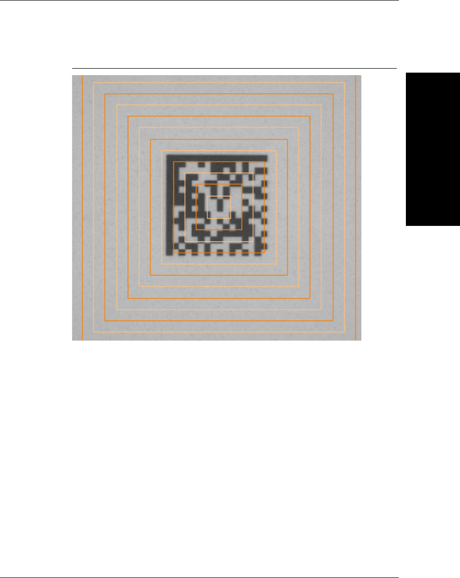
4. Click Live Video. Position the higher contrast (about 80%) Data Matrix on
the Microscan Calibration Test Card under the UID Verifier. Center the Data
Matrix on the screen with correct orientation, as shown in Figure 2–8. (For
UID-LDP, the laser lines are at the middle of the FOV). Note that the Data
Matrix can be rotated but one of the “L” borders must be parallel to one of
the lines in the video overlay.
Testing the UID Compliance Verifier
Quickly Using UID
Compliance Verifier
2
v2.3.1, Dec 2008 Getting Started With Your UID Compliance Verifier 2-7
FIGURE 2–8. Data Matrix in Center with Correct Orientation
5. When you are finished positioning the target, click Live Video again (to exit
Live Video).
Chapter 2Quickly Using UID Compliance Verifier
2-8 Getting Started With Your UID Compliance Verifier v2.3.1, Dec 2008
6. Click Read UID Mark to verify the correct report for contrast and cell size.
The contrast should match the value (with tolerance of +/- 2%) shown on the
Calibration Test Card and the cell size should be reported as
0.015 +/- 0.0001 inches, as shown in Figure 2–9.
FIGURE 2–9. Test Calibration Using Contrast & Cell Size
Test the Correct Operation
Note: Cell Contrast is defined differently than the normal contrast value used in
ISO/IEC 15415 and will not match the value shown on the calibration card.
1. Select Reader > Verification Type > MIL-STD-130N (AIM DPM-1-
2006). Ensure that Report is set to First Passing Overall Grade. Click OK.
Testing the UID Compliance Verifier
Quickly Using UID
Compliance Verifier
2
v2.3.1, Dec 2008 Getting Started With Your UID Compliance Verifier 2-9
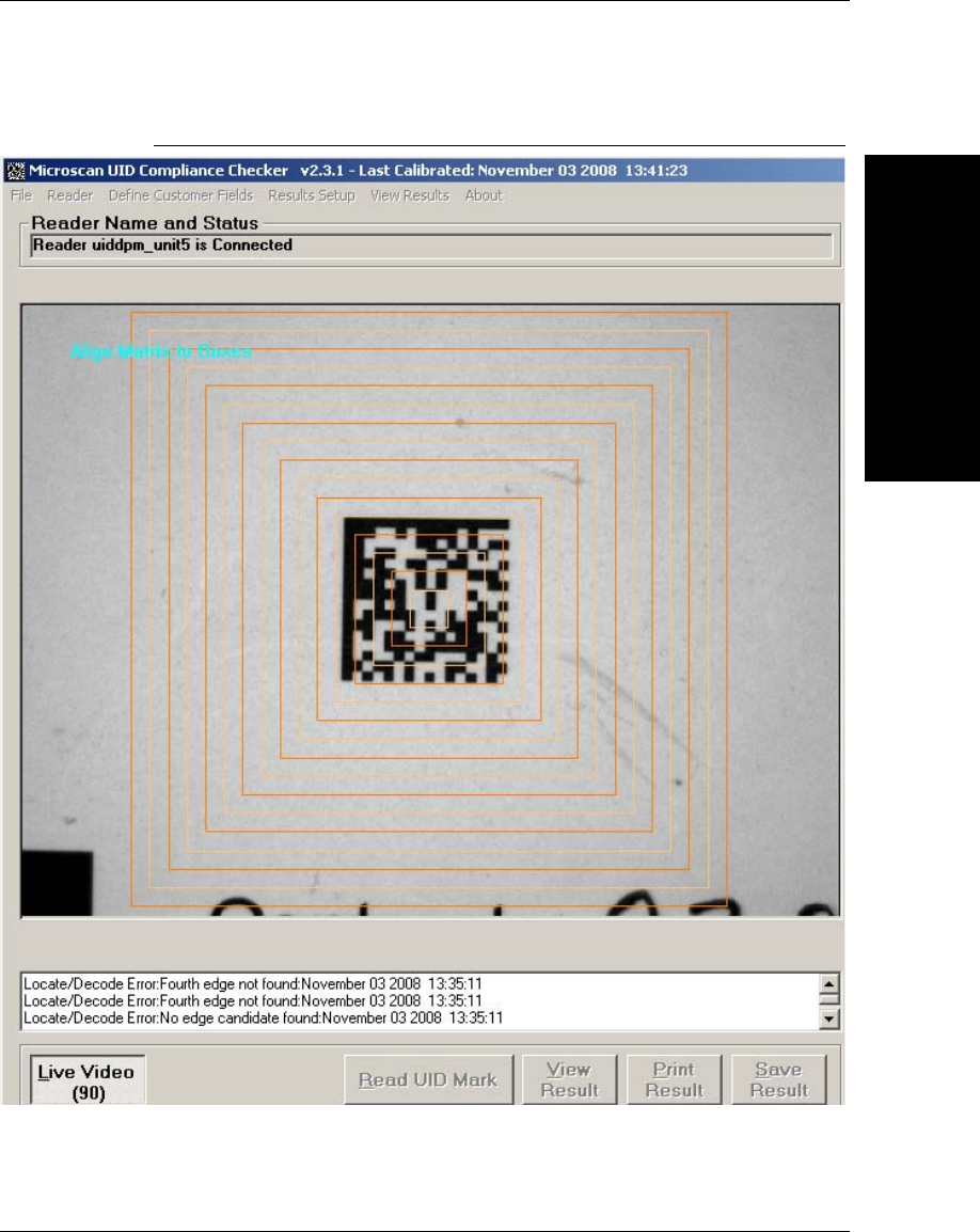
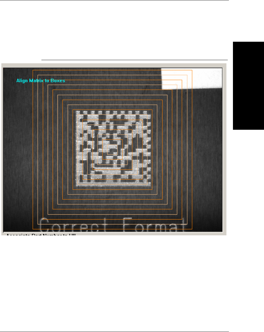
2. Click Live Video and position the UID Compliance Card’s “Correct
Format” Data Matrix in the FOV of the reader, as shown in Figure 2–10.
FIGURE 2–10. Live Video
3. When you are finished positioning the UID Compliance Card's “Correct
Format” Data Matrix, click Live Video again (to exit Live Video).
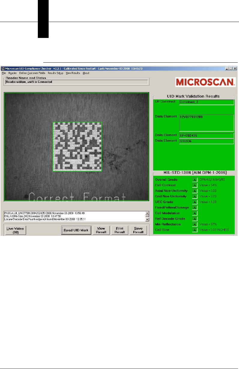
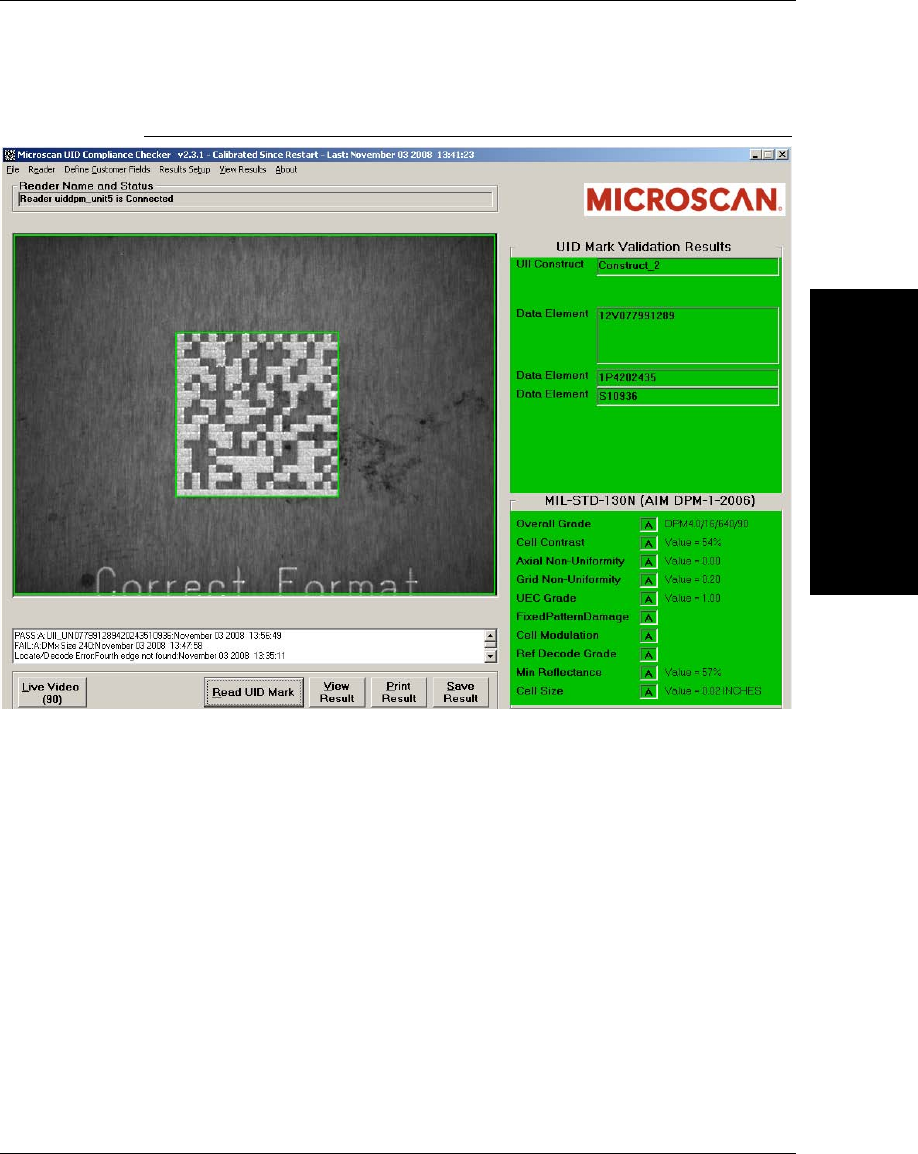
4. Click Read UID Mark and verify that you get a Good read result similar to
the one shown in Figure 2–11. The UID Mark is valid and its contents
correctly formatted.
Chapter 2Quickly Using UID Compliance Verifier
2-10 Getting Started With Your UID Compliance Verifier v2.3.1, Dec 2008
FIGURE 2–11. Good Read Result
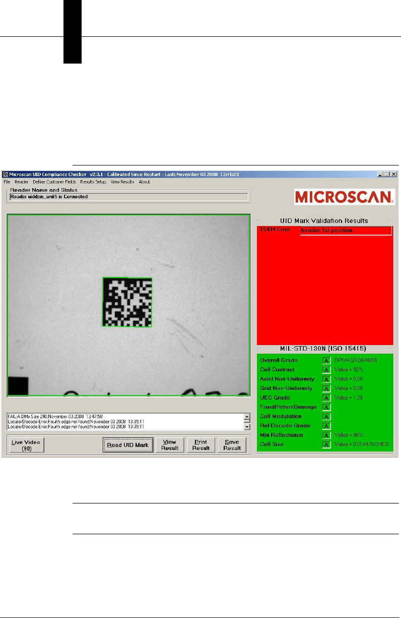
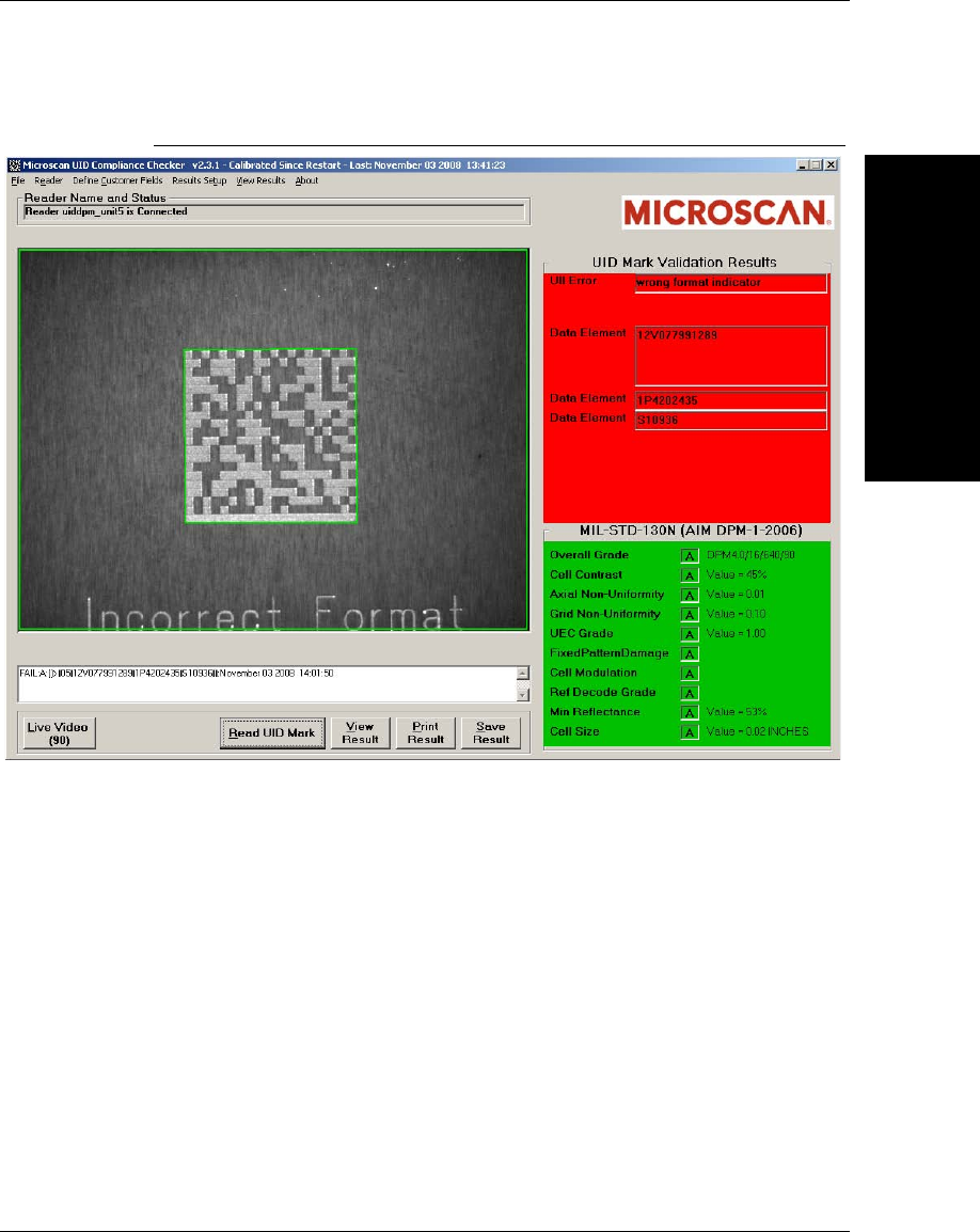
5. Next, repeat the same process using “Incorrect Format” and verify you get a
Fail read result similar to the one shown in Figure 2–12. The UID Mark is
read but the data contents are wrong -- they have an incorrect format -- thus,
the read is trapped as a “Fail”.
Testing the UID Compliance Verifier
Quickly Using UID
Compliance Verifier
2
v2.3.1, Dec 2008 Getting Started With Your UID Compliance Verifier 2-11
FIGURE 2–12. Incorrect Format Read Yields a Failure Result

Chapter 2Quickly Using UID Compliance Verifier
2-12 Getting Started With Your UID Compliance Verifier v2.3.1, Dec 2008

v2.3.1, Dec 2008 Getting Started With Your UID Compliance Verifier 3-1
3
UIDChecker™
Application Details
3
CHAPTER 3 UIDChecker™ Application
Details
In this chapter, we give an overview of UIDChecker™ and then explain each
button, menu item and dialog box.
File Naming Scheme
The UII string is now part of the saved result’s file name:
• In the case of a good read and verification, when you save the results to a
file, the file name consists of the UII String followed by “_Result_” followed
by an auto incrementing result counter. For example:
UN077991289420243510936_Result_00000001.html
• In the case of a bad read, you will get a file name similar to the following:
Not a valid UID Data Matrix_Result_00000050.html
• In the case of Summary reports, for Read And Rotate in the MIL-STD-130L
Change 1 and Overall Grade for All Lights report mode in the MIL-STD-
130M/Change 1 (AIM DPM-1-2006 for DPM) or MIL-STD-130N (AIM
DPM-1-2006), the file name is:
Summary_00000006.html

Chapter 3UIDChecker™ Application Details
3-2 Getting Started With Your UID Compliance Verifier v2.3.1, Dec 2008
Secured UID Verifier
The secured mode in the UID verifier can be enabled by ordering and enabling a
license key from Microscan. Once the verifier is in the secured mode, all image
display features will be disabled. The HawkEye smart camera will not allow a
non-secured firmware version (any version prior to v2.2.0) to be installed that
does not support the secured operation.
UIDChecker™ User Interface Overview
UIDChecker™ will start up and connect automatically to the last reader used and
be ready to read a UID Mark.
While in the UIDChecker™ application, you can “Alt-Tab” to other programs
running on the PC. You can also minimize the UIDChecker™ application.
There are two areas of UID Mark feedback on the display:
• An area to display the image (Figure 3–1)
• An area to display the verification and validation results (Figure 3–1)
UIDChecker™ User Interface Overview
UIDChecker™
Application Details
3
v2.3.1, Dec 2008 Getting Started With Your UID Compliance Verifier 3-3
FIGURE 3–1. UIDChecker™ Main Window
UID Read & Graphical Display Details
Image
A picture box is on the left-hand side of the main display to show the Live Video
display and the last read UID mark image.
Validation Text Result
A color keyed graphical text area is on the upper right-hand side of the main
display. After reading a UID Mark, the background of the text display turns red
or green, depending on the state of the UII string validation. The validation
results are listed clearly in this text display.

Chapter 3UIDChecker™ Application Details
3-4 Getting Started With Your UID Compliance Verifier v2.3.1, Dec 2008
Verification Text Result
A color keyed graphical text area is on the lower right-hand side of the main
display. After reading a UID Mark, the background of the text display turns either
green or red, depending on the state of the UID mark quality verification. The
verification results are listed clearly in this text display.
UID Mark Read Result/Status
The UID Mark Read Result/Status is:
• Pass when both the Validation and Verification are successful, indicated by
green background of the text display
• Fail when at least one of the Validation and Verification is unsuccessful,
indicated by red background of the text display
Light Indicators
UID-LDP has light indicators mounted on the top plate. UID-DPM has light
indicators on both the top and front. The light indicators are illuminated to match
the UID Mark Read Result/Status: red if Fail, green if Pass.
Text Box for UII Only Validation
A text box of the last UID reads appears below the image display. The data to be
displayed is in the following format:
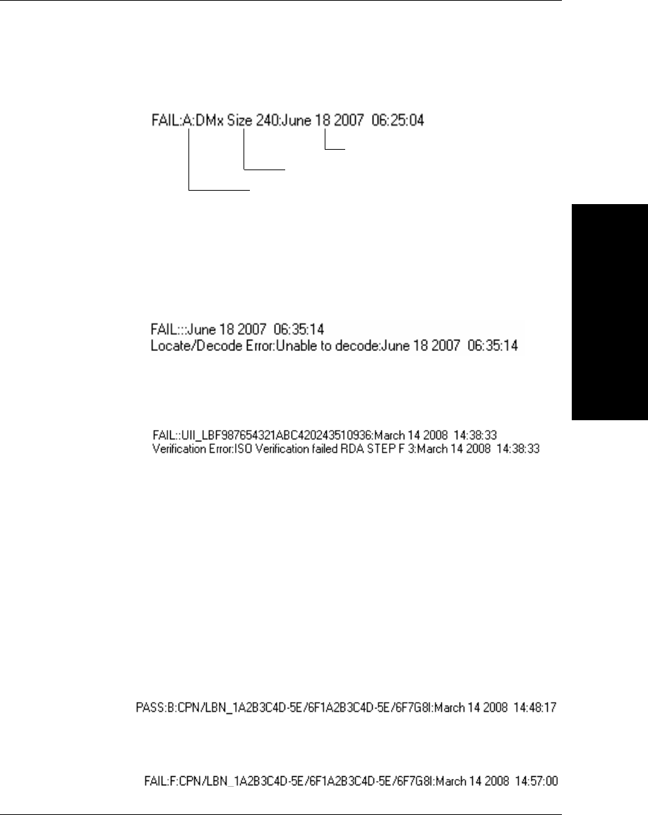
• If the mark:
–Is UII compliant, the line added to the text box will look similar to the
following:
–Has the correct UII format, but the Verification failed, the line added
to the text box will look similar to the following:
Valid UII
Verification Overall Grade
Status
UIDChecker™ User Interface Overview
UIDChecker™
Application Details
3
v2.3.1, Dec 2008 Getting Started With Your UID Compliance Verifier 3-5
–Has an invalid UII format, the line added to the text box will look
similar to the following:
• If an error occurred:
–Locating or decoding the mark, two lines are added to the text box.
The second line begins with “Locate/Decode Error:” followed by the
error code (see Table 3–2, “Data Matrix Locate/Decode Error Codes,”
on page 3-39):
–Verifying the mark, two lines are added to the text box. The second
line begins with “Verification Error:” followed by the error code (see
Table 3–3, “Data Matrix Verification Error Codes,” on page 3-40):
Text Box for CPN/LBN Only Validation
A text box of the last UII reads appears below the image display. By default, a
Current Part Number (CPN) or Lot/Batch Number (LBN) mark will be rejected
as an invalid UII format. To validate a CPN/LBN, select Results Setup >
Enable CPN/LBN Support. The data to be displayed is in the following format:
• If the mark:
–Is validated as PNR, 30P, 240, or 30T, the line added to the text box
will look similar to the following:
Note: The part number is displayed in the CPN/LBN_ text box below
the image display.
–Has the correct CPN/LBN format, but the Verification failed, the
line added to the text box will look similar to the following:
Date & Time of Read
Raw Data (Original Data Matrix Data)
Verification Overall Grade
Chapter 3UIDChecker™ Application Details
3-6 Getting Started With Your UID Compliance Verifier v2.3.1, Dec 2008
–Has an invalid CPN/LBN format, the line is the same as “Has an
invalid UII format” in UID Validation:
•If an error occurred, the result is the same as those in UID Validation.
Text Box for Validating UII & CPN/LBN in a Single Symbol
To validate both UII and CPN/LBN in a single Data Matrix symbol, select
Results Setup > Enable CPN/LBN Support. In addition to the formats
described in “Text Box for UII Only Validation” and “Text Box for CPN/LBN
Only Validation”, you may also see the following cases:
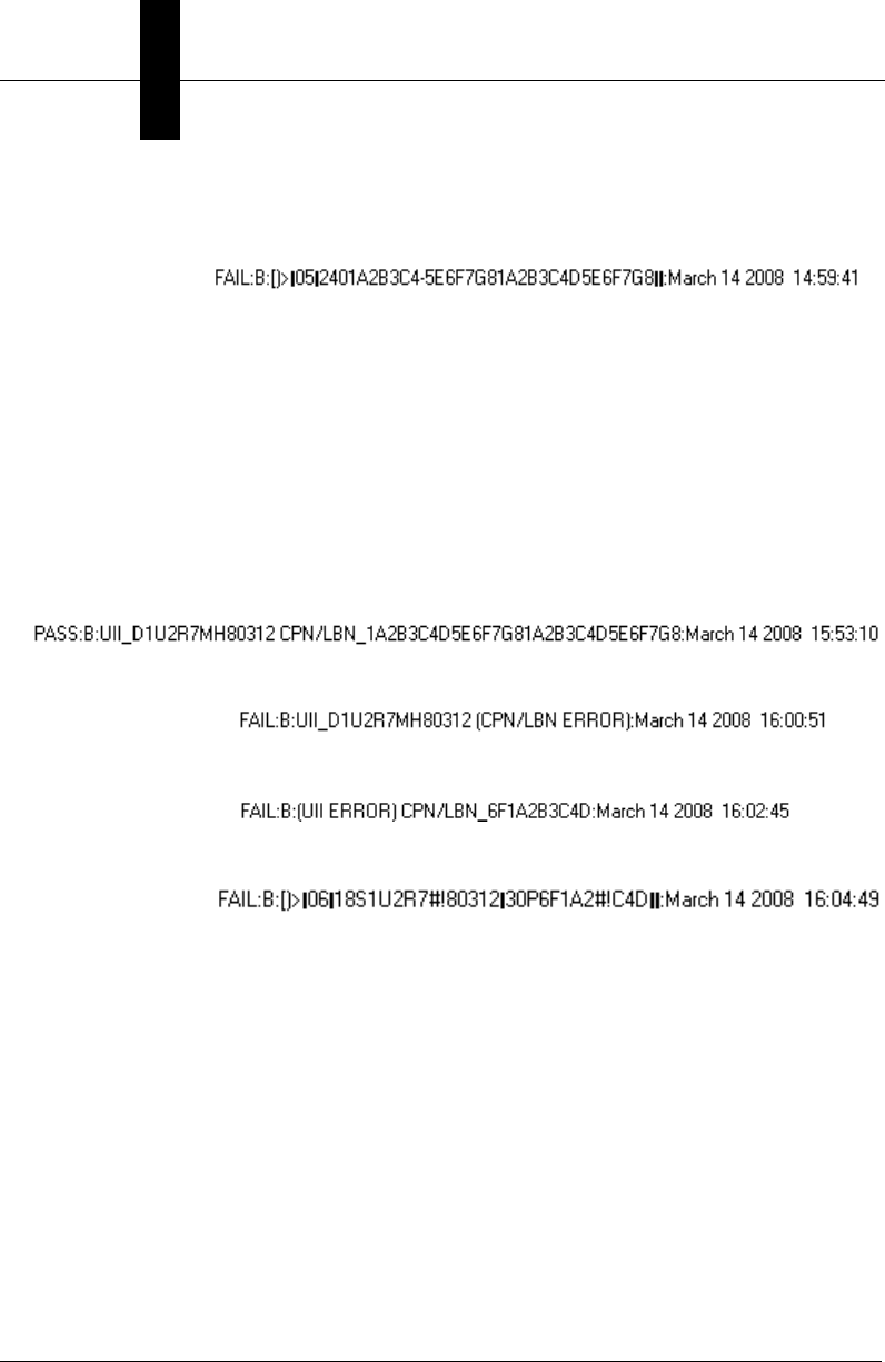
• If the mark has:
–Valid UII and CPN/LBN:
–Valid UII and invalid CPN/LBN:
–Invalid UII and valid CPN/LBN:
–Invalid UII and CPN/LBN:
The text box has scroll bars for scrolling back to previous read results. There is a
limit of 20 UII read results that can be displayed in this region. The Clear Log
button on the “Results Setup Dialog” allows you to clear manually the text box.
Upon restart of this UIDChecker™ application, the text box is cleared
automatically.
UIDChecker™ Buttons Overview
UIDChecker™
Application Details
3
v2.3.1, Dec 2008 Getting Started With Your UID Compliance Verifier 3-7
UIDChecker™ Buttons Overview
Tool tips are available for each of the main buttons shown in Figure 3–2:
FIGURE 3–2. UIDChecker™ Main Buttons
• “Live Video” starting on page 3-7
• “Read And Rotate” starting on page 3-8
• “Read UID Mark” starting on page 3-8
• “View Result” starting on page 3-9
• “Print Result” starting on page 3-9
• “Save Result” starting on page 3-9
Live Video
Use the Live Video button to position a mark in the FOV of the reader. Note that
the Data Matrix must be completely within the screen for a successful read. For
UID-LDP, the laser lines are at the middle of the FOV.
Live Video is enabled once connected to a UID reader. Clicking Live Video
displays the live video from a reader on the user interface. Clicking Live Video a
second time stops the Live Video update. If Live Video is enabled, all other user
interface buttons and drop down menus are disabled until the Live Video update
is complete. When the Live Video update is complete, the result text display is
cleared.
When the verification type is set to MIL-STD-130M/Change 1 (AIM DPM-1-
2006 for DPM) or MIL-STD-130N (AIM DPM-1-2006), Live Video can adjust
automatically the exposure to obtain the proper contrast of the mark. In UID-
DPM, Live Video can be used to display images for each supported light
configuration.

Chapter 3UIDChecker™ Application Details
3-8 Getting Started With Your UID Compliance Verifier v2.3.1, Dec 2008
For a secured UID verifier, LiveVideo displays the outline of the Data Matrix
mark without the image itself. To improve the responsiveness of the live video, it
is recommended that the Data Matrix be centered using fixtures.
Read And Rotate
The Read And Rotate button is visible when you select the MIL-STD-130L
Change 1 (ISO 15415) Verification Type. Refer to Appendix B, “Read And
Rotate,” for details.
Read UID Mark
After you click Read UID Mark, reading and decoding may take up to one
second. Once the mark is read, the PC screen and the light will be updated to
reflect the UID compliance and the mark quality verification status.
Note: If the verification type is set to MIL-STD-130M Change 1 (AIM DPM-1-
2006 for DPM) or MIL-STD-130N (AIM DPM-1-2006) with a report mode of
Overall Grade For All Lights, a sequence of images are taken with different
lights and will take longer than one second.
Note: F8 is the hotkey to read a mark; it simulates a mouse click on the Read
button. Also, the Read button retains the focus of the application, so clicking the
Enter button on the Keyboard will also begin a “Read”. The UIDChecker
application must be in focus for these hotkeys to work.
Analyzing the Results of UID Compliance Check
If the Data Matrix mark is a valid UID mark and is verified to be of good quality,
then both the Validation and Verification panels at the right of the screen will
become green. The light on top of the unit will also show green.
If either the validation or the verification test failed, the appropriate panel will be
red and the light on top of the unit will show red.
If the UID mark is valid, then the validation results panel reports the UID mark
components. As long as the Data Matrix can be decoded and verified, the
verification panel shows the grading on each of the verification parameters
corresponding to the verification type specified.

UIDChecker™ Buttons Overview
UIDChecker™
Application Details
3
v2.3.1, Dec 2008 Getting Started With Your UID Compliance Verifier 3-9
Results
When a mark is decoded, extra buttons appear on the screen: View Results, Print
Results and Save Results. A complete description of the Results can be found on
“View Results” starting on page 3-28.
View Result
Select View Result to see the full UID Mark report including the image. This
will transfer you to the results display. From here, you can manage your UII read
results. This is fully explained in “View Results” starting on page 3-28.
Note: The image will contain only the outline of the Data Matrix for a secured
UID verifier.
Print Result
Select Print Result to send the current UID Read report to the PC’s default
printer. Print Result combines the last UID Mark read image, compliancy results,
and the customer defined fields onto a one sheet 8½ x 11 inch printout. Then, you
can specify your local or network printer.
Note: The button is only enabled when the result text area of the screen contains
data.
These results contain a Microscan logo and uidsupport contact information. This
logo may be replaced with a customer-selected bitmap of appropriate size. See
“Define Customer Fields” on page 3-21.
Save Result
Select Save Result to save the current UID Read results and the image to a file
on the PC’s hard drive. This button is enabled if automatic logging of read results
is OFF. Clicking Save Result appends the read results, including the name of
the image file, to the data file.
Note: The button is only enabled when the result text area of the screen contains
data.

Chapter 3UIDChecker™ Application Details
3-10 Getting Started With Your UID Compliance Verifier v2.3.1, Dec 2008
Main Menu Items
The main menu items are:
• “File” starting on page 3-10
• “Reader” starting on page 3-10
• “Define Customer Fields” starting on page 3-21
• “Results Setup” starting on page 3-22
• “View Results” starting on page 3-28
• “About” starting on page 3-36
File
Exit
This menu item exits the UIDChecker™ application. This button allows a
graceful exit from the UIDChecker™ program. The laser and LEDs are shut off
when the UIDChecker™ program is exited.
Reader
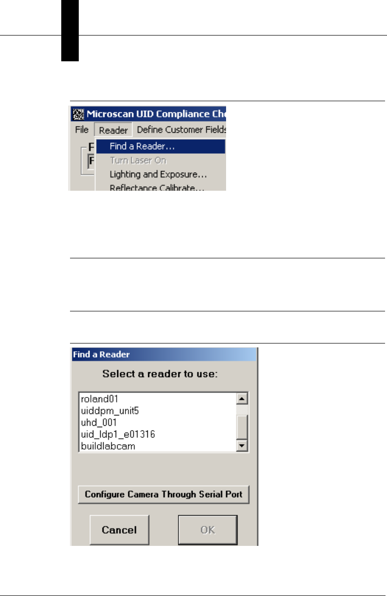
Find a Reader
This menu item launches an applet to show all the readers on the customer’s
network. The customer needs to simply browse the display of readers and, with
his mouse, select his reader from the list.
Main Menu Items
UIDChecker™
Application Details
3
v2.3.1, Dec 2008 Getting Started With Your UID Compliance Verifier 3-11
FIGURE 3–3. Drop Down List of Readers
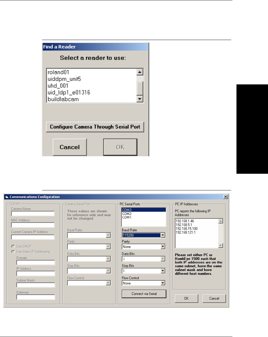
If the reader cannot be found, select the Configure Camera Through Serial
Port button to display the dialog box shown in Figure 3–4:
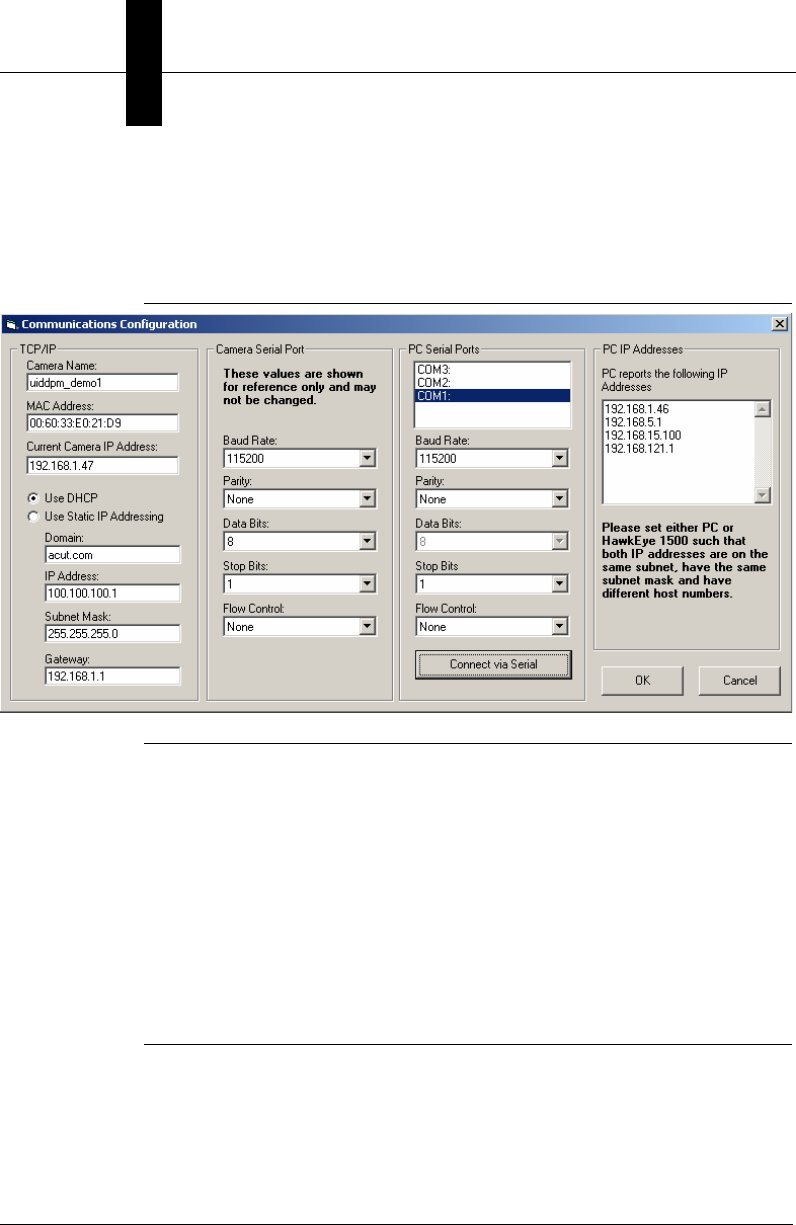
FIGURE 3–4. Communications Configuration
Chapter 3UIDChecker™ Application Details
3-12 Getting Started With Your UID Compliance Verifier v2.3.1, Dec 2008
With the serial cable plugged in to the PC’s COM port and the UID verifier,
select the correct PC Serial Ports then click the Connect via Serial to display the
screen displayed in Figure 3–5:
FIGURE 3–5. Communications Configuration — After Successful Connection
Notes: The camera serial port in the UID verifier is configured at the factory with
the setting: Baud Rate 115200, Parity None, Data Bits 8, Stop Bits 1, Flow
Control None. The serial port setting for PC Serial Ports are locked to be the
same as the camera and cannot be changed.
If your PC has more than one serial port and you select the wrong serial port from
PC Serial Port and click the Connect via Serial button, the software will take a
long time to time out and fail to make the connection. When this happens, it is
possible that you will not be able to connect the PC to the camera even though
you then select the correct serial port. You need to click the Cancel button on
each of the two dialogs and then exit UIDChecker. Restart UIDChecker, select
the correct PC serial port, and click the Connect via Serial button again.
To ensure Ethernet communication, you need to set either PC or the UID verifier
such that both IP addresses are on the same subnet, have the same subnet mask
and have different host names. In the above example, the UID verifier IP address
is 192.168.1.47 and the PC IP address is 192.168.1.46.
Main Menu Items
UIDChecker™
Application Details
3
v2.3.1, Dec 2008 Getting Started With Your UID Compliance Verifier 3-13
Turn Laser Off
When this menu item is clicked, the laser on the UID-LDP verifier can be turned
off and the menu option will be re-captioned to be “Turn Laser On”. Clicking
Turn Laser On will turn the laser on and re-caption this menu option to “Turn
Laser Off”.
Calibrate
You MUST calibrate your UID-LDP and UID-DPM upon first time startup in
your production area and, again, if you move the UID reader or the ambient light
changes. The work environment where you will use your UID reader should be a
stable environment in terms of lighting. For example, if you work in an office
near windows, there might be read considerations when you perform a read at
noontime on a sunny day versus a read performed during 3rd shift at 2AM on a
moonless night. We suggest you position the UID reader in a fairly steady-state
lighting environment where ambient light is consistent and at a low level.
For certain verification types, such as AS9132 Dot Peen, where contrast is not
read or reported, calibration is performed to simply relate pixel size to
dimensional units. In this case, the camera should be calibrated normally using
the supplied calibration target, and then photometry values may be changed to
obtain good images with dark or reflective samples.
The UID-LDP and UID-DPM comes with a Calibration Target (Microscan part
number 98-UA10-0CC0). Once you have positioned your UID-LDP and UID-
DPM into your work space, you need to re-calibrate the system using this
Calibration Target.
1. Position the Data Matrix (around 80% contrast) under the UID-LDP or
UID-DPM.
Caution
If the targeting lasers are activated, do not stare into the beams. The UID-LDP’s
targeting lasers have been rated as Class II lasers by IEC 60825-1.
Warning
DO NOT LOOK DIRECTLY AT THE BEAMS OF THE LASER!
Chapter 3UIDChecker™ Application Details
3-14 Getting Started With Your UID Compliance Verifier v2.3.1, Dec 2008
2. Click Reader -> Reflectance Calibrate to bring up the Calibration dialog
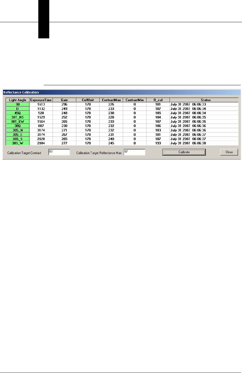
box, as shown in Figure 3–6.
FIGURE 3–6. Calibration Dialog Box
– Light Angle — Displays light configurations (or light angle) available
to the connected UID verifier. For UID-LDP, only 90 is displayed.
– Exposure Time — Displays exposure time for the HawkEye 1500
camera corresponding to each light configuration. These values are
normalized at factory and will not change by the Reflectance
Calibration.
– Gain — Displays camera gain control value for the HawkEye 1500
camera corresponding to each light configuration. These values are
normalized at factory and will not change by the Reflectance
Calibration.
– CellUnit — Displays how the verifier relates pixel values to inches for
each light. All the values displayed should be the same or vary by no
more than +/- 1.
– ContrastMax/ContrastMin — These values are used to calibrated
contrast value for all verification type except MIL-STD-130M/Change
1 (AIM DPM-1-2006 for DPM) or MIL-STD-130N (AIM DPM-1-
2006). These are calibrated by the reflectance calibration.
– R_cal — These values are calibrated for MIL-STD-130M/Change 1
(AIM DPM-1-2006 for DPM) or MIL-STD-130N (AIM DPM-1-2006)
for reporting Minimum Reflectance.
– Status — Displays the date and time when the reflectance calibration
takes place. If unsuccessful, error messages are displayed here.
Main Menu Items
UIDChecker™
Application Details
3
v2.3.1, Dec 2008 Getting Started With Your UID Compliance Verifier 3-15
3. In the Cal. Target Contrast text box, enter the value associated with the Data
Matrix (80% contrast) you are using as the target. For example, if the
contrast marked for the Data Matrix on the Calibration Test Card is 82.6%,
you would enter 82.6 or 83.
4. In the Cal. Target Reflectance Max text box, enter the value associated with
the Data Matrix (80% contrast) you are using as the target. For example, if
the R_max marked for the Data Matrix on the Calibration Test Card is
87.4%, you would enter 87.4 or 87.
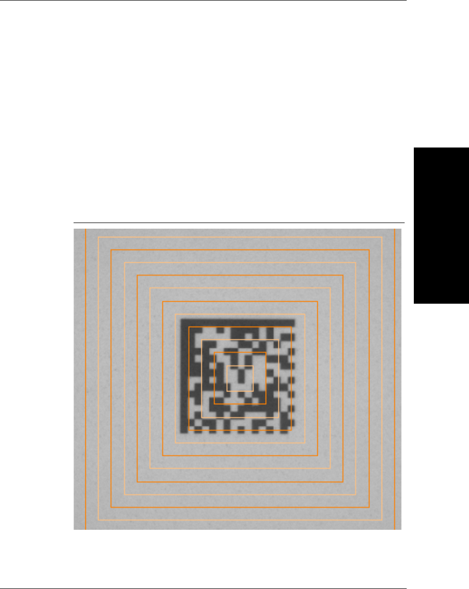
5. The Live Video mode is enabled. Center the Data Matrix (about 80%
contrast) on the Calibration card in the camera’s FOV.
FIGURE 3–7. Data Matrix Centered in FOV
6. Click Calibrate.
Chapter 3UIDChecker™ Application Details
3-16 Getting Started With Your UID Compliance Verifier v2.3.1, Dec 2008
The UIDChecker™ will calibrate the reader in less than 10 seconds or post
error messages if it can’t. All calibration data are saved to the verifier. The
top border of the UIDChecker™ application will show the last calibration
date. Also, the calibration date will be posted in the Results display.
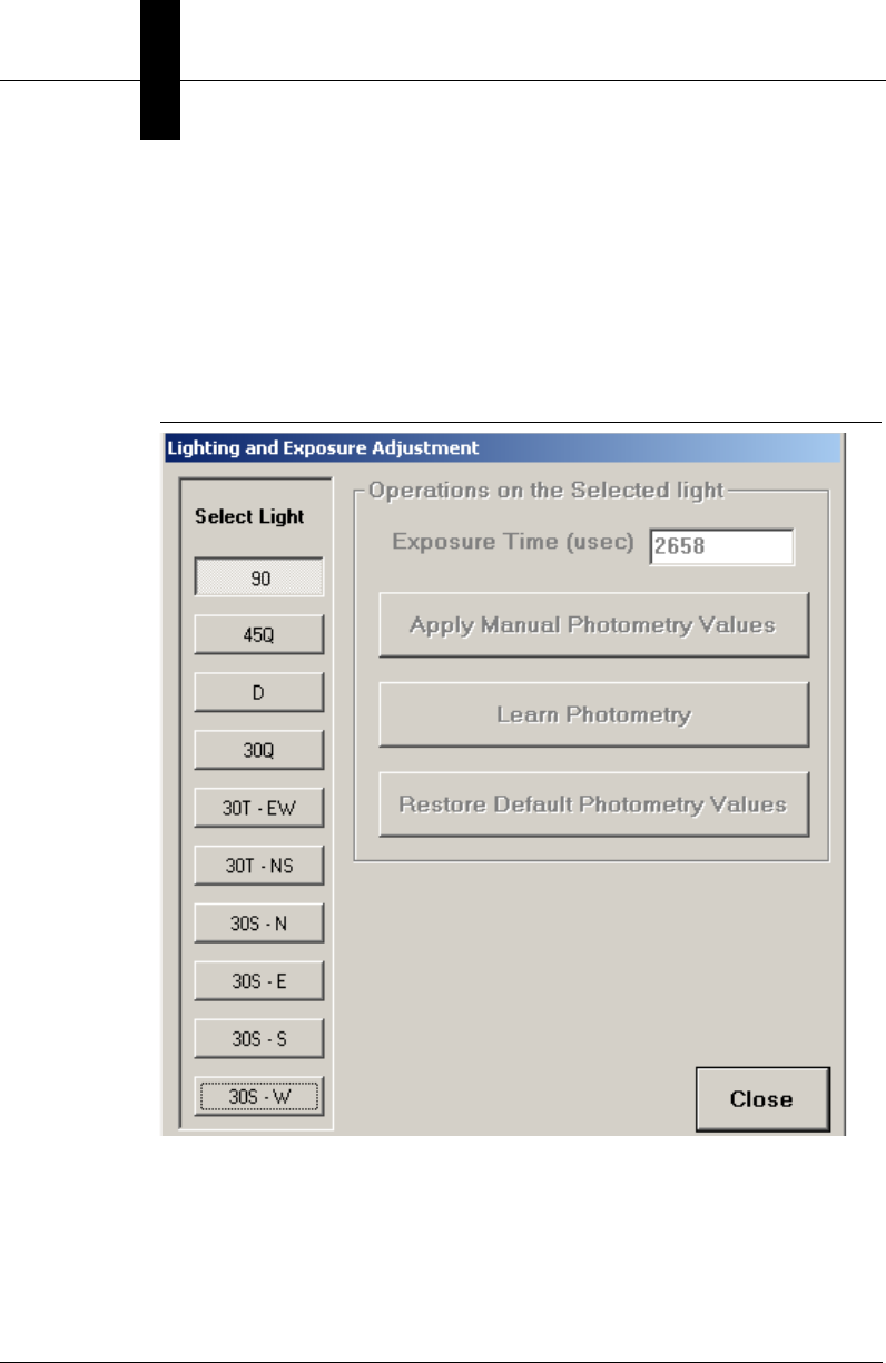
Lighting & Exposure
FIGURE 3–8. Lighting & Exposure Adjustment Dialog Box
• Select Light — In UID-DPM, for the MIL-STD-130M/Change 1 (AIM
DPM-1-2006 for DPM) or MIL-STD-130N (AIM DPM-1-2006)
verification types, all supported light configurations are displayed. You can
select a light configuration and use it for live video display. For other
verification types in UID-DPM, only light configuration 90 is displayed and
enabled. For UID-LDP, only 90 is displayed.
Main Menu Items
UIDChecker™
Application Details
3
v2.3.1, Dec 2008 Getting Started With Your UID Compliance Verifier 3-17
• Operations on the Selected Light — This group is disabled for the MIL-
STD-130M/Change 1 (AIM DPM-1-2006 for DPM) or MIL-STD-130N
(AIM DPM-1-2006) verification type as photometry and exposure control is
done automatically in the software based on the Mean Light requirement in
AIM DPM-1-2006. The Exposure Time box always displays the current
exposure time used in the camera corresponding to the selected light
configuration. Note that the gain values are set at the factory and will never
change.
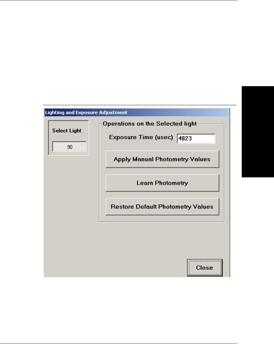
FIGURE 3–9. Lighting & Exposure Adjustment Dialog Box
To adjust the exposure automatically, press the Learn Photometry button to
obtain an image with good intensity and contrast and the new exposure time will
be displayed. If the image needs further adjustment, manually enter the exposure
time then select Apply Manual Photometry Values button. The Default button
resets exposure time to the factory calibrated exposure time for the selected light
configuration.
Chapter 3UIDChecker™ Application Details
3-18 Getting Started With Your UID Compliance Verifier v2.3.1, Dec 2008
For the verification type MIL-STD-130M/Change 1 (AIM DPM-1-2006 for
DPM) or MIL-STD-130N (AIM DPM-1-2006), Live Video automatically adjusts
the exposure to produce images with acceptable contrast that allow you to
correctly position the mark in the FOV. Once a Data Matrix mark is correctly
positioned using one of the light configurations, the software will further adjust
the exposure during the verification and the new exposure values determined by
the verification algorithm for all light configurations will be available to be
displayed in the Exposure Time edit box. For each light configuration, Live
Video will always use the current exposure time and the verification algorithm
will always start with the current exposure time and adjust it when necessary.
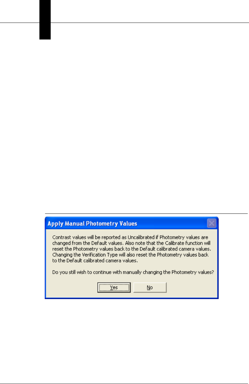
For all other verification types except MIL-STD-130M/Change 1 (AIM DPM-1-
2006 for DPM) or MIL-STD-130N (AIM DPM-1-2006), if the image in Live
Video does not have sufficient intensity or contrast, exit the Live Video and
display the Lighting and Exposure Adjustment dialog box to adjust the exposure
automatically or manually. Adjusting exposure will not invalidate the size
calibration, but contrast will be reported as Uncalibrated until the next calibration
is performed. Figure 3–10 warns you of the consequences of changing
photometry values after calibration.
FIGURE 3–10. Consequences of Changing Photometry
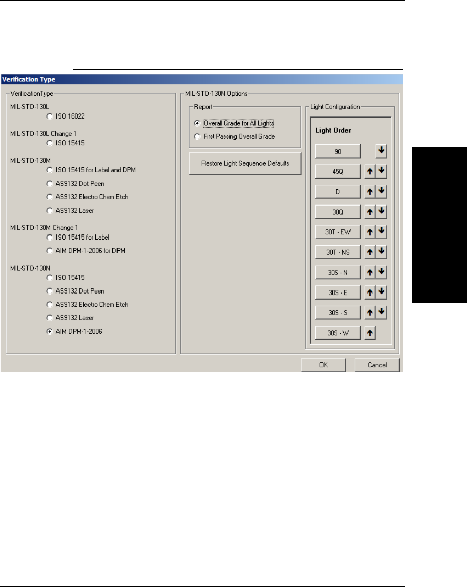
Verification Type
You must set the UIDChecker™ to use the Verification Standard most fitting to
your application by using this drop down menu item. Click on Verification Type
to bring up the Verification Type dialog box, as shown in Figure 3–11. The
default Verification Type is MIL-STD-130N (AIM DPM-1-2006).
Main Menu Items
UIDChecker™
Application Details
3
v2.3.1, Dec 2008 Getting Started With Your UID Compliance Verifier 3-19
FIGURE 3–11. Default Verification Type
The verification types MIL-STD-130M Change 1 (AIM DPM-1-2006 for
DPM) and MIL-STD-130N (AIM DPM-1-2006) have the same implementation
of AIM DPM-1-2006 verification standard.
•For MIL-STD-130M Change 1 (AIM DPM-1-2006 for DPM), the grade
requirement is DPM2.0/7.5-25/640/(45Q|30Q|90|30T|30S) for UID-DPM
and DPM2.0/7.5-25/640/90 for UID-LDP.
•For MIL-STD-130N (AIM DPM-1-2006), the grade requirement is
DPM2.0/7.5-25/640/(45Q|30Q|90|30T|30S|D) for UID-DPM and
DPM2.0/7.5-25/640/90 for UID-LDP.
The difference between these two verification options is that the D (Dome) light
is only available for MIL-STD-130N (AIM DPM-1-2006) for UID-DPM.

Chapter 3UIDChecker™ Application Details
3-20 Getting Started With Your UID Compliance Verifier v2.3.1, Dec 2008
For UID-DPM, the grade requirement of
DPM2.0/7.5-25/640/(45Q|30Q|90|30T|30S|D) means that the overall grade must
be at least 2.0 for X dimension range 7.5-25 and wavelength 640 from at least
one of the light configurations 45Q, 30Q, 90, 30T, 30S, and D.
For UID-LDP, the grade requirement of DPM2.0/7.5-25/640/90 means that the
overall grade must be at least 2.0 for X dimension range 7.5-25 and wavelength
640 from the light configurations 90.
When the verification type MIL-STD-130M Change 1 (AIM DPM-1-2006 for
DPM) or MIL-STD-130N (AIM DPM-1-2006) is selected, the light specified as
the first one in the Light Configuration is turned on if it is not already on. (To
switch to a different light angle, use the Reader > Lighting and Exposure). The
following options will become available:
• Report — Two options are available:
– Overall Grade for All Lights — When this option is selected,
UIDChecker™ performs verification for each enabled light
configuration and reports the result corresponding to each light
configuration in a Summary Report.
– First Passing Overall Grade — This is the default. This option can speed
up the verification process. When this option is selected, UIDChecker™
performs verification for all enabled light configurations according to
the specified light order. As soon as the overall grade from a light
configuration meets the minimum passing grade, UIDChecker™
outputs the result without trying the remaining light configurations.
• Light Configuration — The light configuration option allows 90, 30Q, 30T,
45Q, 30S and D to be re-ordered. The Light order is listed from top to
bottom. Using the “up” and “down” arrows behind each light configuration,
you can adjust the light order such that certain light configurations that are
more likely to produce the higher overall grade are tried first. For UID-LDP,
only light configuration 90 (Diffuse perpendicular) is enabled.
When a verification type other than MIL-STD-130M Change 1 (AIM DPM-1-
2006 for DPM) or MIL-STD-130N (AIM DPM-1-2006) is selected, the light
configuration 90 is turned on if it is not already on for both UID-LDP and UID-
DPM. No other light configurations will be available unless the verification type
is MIL-STD-130M Change 1 (AIM DPM-1-2006 for DPM) or MIL-STD-
130N (AIM DPM-1-2006).
Main Menu Items
UIDChecker™
Application Details
3
v2.3.1, Dec 2008 Getting Started With Your UID Compliance Verifier 3-21
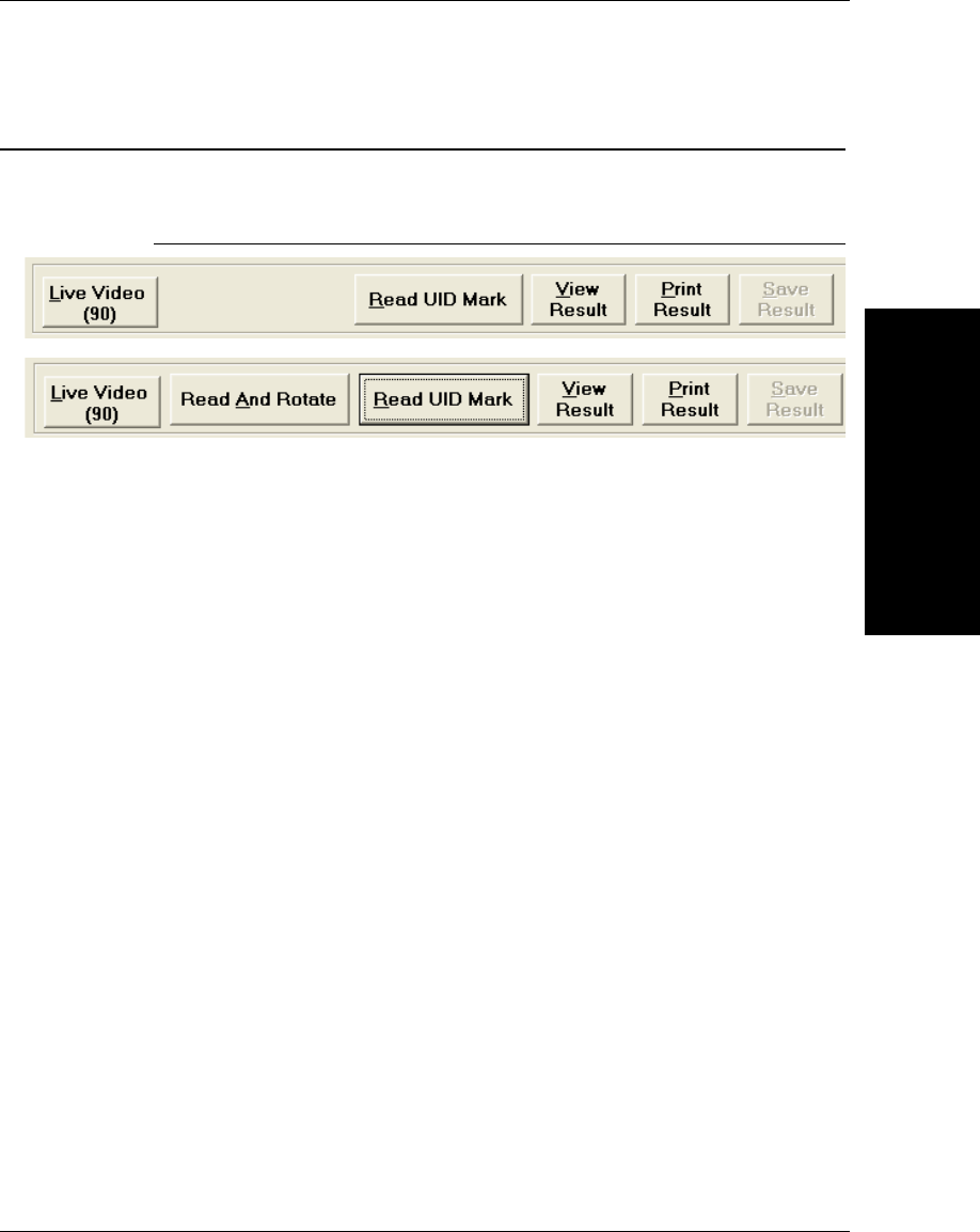
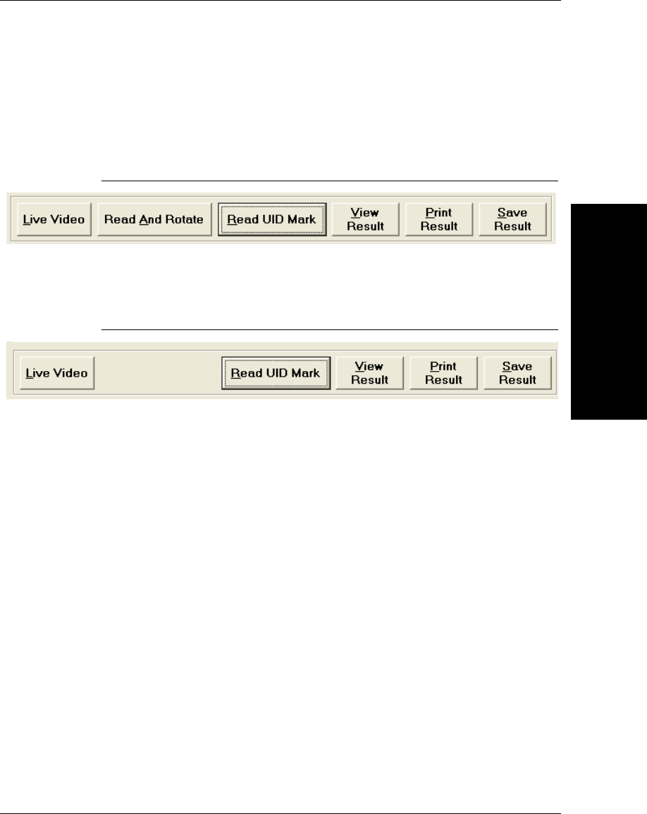
When verification type MIL-STD-130L Change 1 (ISO 15415) is selected, the
main buttons on the UIDChecker™ interface are as shown in Figure 3–12. The
Read And Rotate button appears only when MIL-STD-130L Change 1 (ISO
15415) verification is selected. See Appendix B, “Read And Rotate,” for details.
FIGURE 3–12. Main Buttons — Read And Rotate Visible
Otherwise, the main buttons on the UIDChecker™ interface are as shown in
Figure 3–13.
FIGURE 3–13. Main Buttons
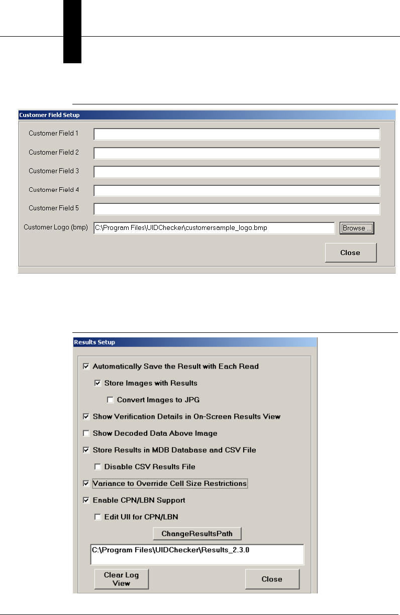
Define Customer Fields
This option allows you to specify up to five lines of 80-character ASCII that will
be included in the printed report and stored with each record in the log file. Also,
it allows you to specify your company’s logo (.bmp file) to be included on the
printed and on-screen reports. The logo should not exceed 300 pixels wide and
70 pixels high.
Chapter 3UIDChecker™ Application Details
3-22 Getting Started With Your UID Compliance Verifier v2.3.1, Dec 2008
FIGURE 3–14. Define Customer Field Settings Dialog Box
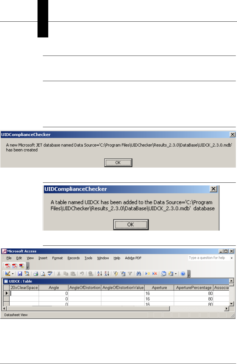
Results Setup
FIGURE 3–15. Results Setup Dialog Box

Main Menu Items
UIDChecker™
Application Details
3
v2.3.1, Dec 2008 Getting Started With Your UID Compliance Verifier 3-23
Automatically Save the Result with Each Read
This checkbox enables/disables the automatic saving of UID mark results. By
default, automatic saving is disabled -- OFF.
If the option is not selected, the user is not allowed to “Store Images With
Results” because there are no results to save them with. And since no images are
being stored, the user is not allowed to “Convert Images to JPG”.
Store Images With Results
This checkbox enables/disables the automatic saving of the UID Mark read
Image with each result. By default, automatic image storing is enabled -- ON.
Convert Image to JPG
This checkbox enables/disables the image format as JPG. When disabled, BMP
image format is used.
Show Verification Details in On-Screen Results View
This checkbox enables/disables the viewing of verification and validation details.
By default, this setting is disabled -- OFF.
Show Decoded Data Above Image
This checkbox enables/disables the viewing of the Decoded Data string. By
default, this setting is disabled -- OFF.
Store Results in MDB Database and CSV File
This checkbox enables/disables the writing of Results to an MDB Database. By
default, this setting is disabled -- OFF.
When this option is enabled, the UIDChecker™ will write the inspection results
into an MDB database. This setting is saved in the registry for the user so that it is
remembered the next time UID Verifier is started. The results may be read by any
application, such as Access, that does not lock out writes to the database.
For customers that prefer to obtain results from an MDB database and not the
CSV, comma-delimited file, an option has been provided to disable CSV Results
File.
When the option Store Results in MDB Database and CSV File is
de-selected, there is no CSV Results File to disable.
Chapter 3UIDChecker™ Application Details
3-24 Getting Started With Your UID Compliance Verifier v2.3.1, Dec 2008
Note: Opening an MDB or Access in Excel locks the database so that new
records can’t be written by UID Verifier. In this case, a copy of the database may
be created and opened.
The first time a reading is taken after enabling the database, the dialogs boxes in
Figure 3–16 through Figure 3–18 are displayed to provide positive feedback that
the database was created and the table within the database was created.
FIGURE 3–16. MDB Database Startup Sequence
FIGURE 3–17. MDB Database Startup Sequence Continued
FIGURE 3–18. Microsoft Access View
Database Table Layout
For detailed database layout, see “Version 2.3 DataBase Table Layout” on
page 4-7.
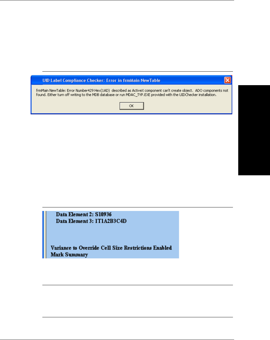
Main Menu Items
UIDChecker™
Application Details
3
v2.3.1, Dec 2008 Getting Started With Your UID Compliance Verifier 3-25
Possible ADO Component Error Messages
If the ADO components on the PC where UIDChecker™ is installed are missing
or a very old version, the message box in Figure 3–19 will appear.
FIGURE 3–19. Possible Error Messages if ADO is Out of Date or Missing
To fix this problem, see Appendix E, “Fixing ADO Components Error,” for more
information.
Variance to Override Cell Size Restrictions
If you have received a variance, you can disable the test for cell size by selecting
the Variance to Override Cell Size Restrictions check box, as shown in
Figure 3–15.
Cell Size is still measured and reported but the results are marked with a
statement that the variance is enabled, as shown in Figure 3–20.
FIGURE 3–20. Variance to Override Cell Size Restrictions Enabled
In addition, the .CSV and .MDB results will have the OverrideCellSize field set
to TRUE.
Note: The variance flag has no effect on the MIL-STD-130M/Change 1 (AIM
DPM-1-2006 for DPM) or MIL-STD-130N (AIM DPM-1-2006) verification
type, as MIL-STD-130M/Change 1 and MIL-STD-130N require the cell size to
be within 0.0075 inches and 0.025 inches.
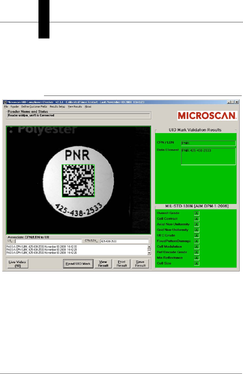
Chapter 3UIDChecker™ Application Details
3-26 Getting Started With Your UID Compliance Verifier v2.3.1, Dec 2008
Enable CPN/LBN Support
When this option is selected, the Associate CPN/LBN to UII frame is displayed
below the image on the user interface of UIDChecker™.
FIGURE 3–21. CPN/LBN Support Selected
If the Enable CPN/LBN Support option is selected, and a UID mark is read, it
is validated and verified the same way as if the Enable CPN/LBN Support
option is de-selected. If a CPN/LBN mark is read after reading a validated UID
mark, it is validated against ISO/IEC 15434 and must be of the type PNR, 30P,
240, or 30T to be considered successful. When validated, the CPN/LBN mark is
reported as PNR, 30P, 240, or 30T and is associated with the last UID mark. The
verification report notes the associated UII string and associated CPN/LBN, the
report filename is a concatenation of UII and CPN/LBN, and the database also
records the association.
If, prior to reading a CPN/LBN mark, a failure to validate a mark occurred, it is
assumed that the UID mark failed to read and the CPN/LBN mark is reported
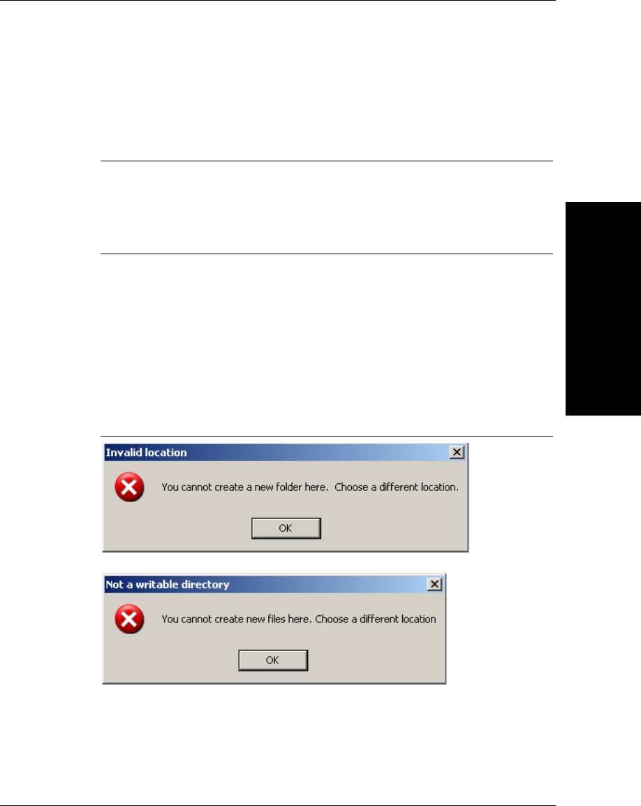
Main Menu Items
UIDChecker™
Application Details
3
v2.3.1, Dec 2008 Getting Started With Your UID Compliance Verifier 3-27
without an association to a UID mark. If the option Edit UII for CPN/LBN is
enabled, the edit box where the UII is normally displayed becomes a writable
field, and a UII may be manually entered to be associated with subsequent reads
of CPN/LBN marks.
Note: It is operator’s responsibility to enter the correct UII when the Edit UII for
CPN/LBN option is used. If an incorrect UII string is entered, it will be used
without validation in the verification report, file name generation, database, and
CSV file. It is recommended that another reader, such as a UII validation enabled
handheld, be used to generate the correct UII string.
Change Results Path
From this text box, you can redirect output files to a network drive for either
backup or disaster management.
UIDChecker™ checks that protections are set correctly so that new directories
can be created and results written to the remote system. If protections are not set
correctly, you will see either of the messages in Figure 3–22.
FIGURE 3–22. Message(s) Displayed When Protections Not Set Correctly
Clear Log View
This button clears or resets the Data Log View on the main screen.

Chapter 3UIDChecker™ Application Details
3-28 Getting Started With Your UID Compliance Verifier v2.3.1, Dec 2008
Close
This button closes the Results Setup dialog.
View Results
View Results allows you to view and manage your UIDChecker™ result records.
This interface can also view, search, archive, print or delete results.
Note: In version 2.3, result records are stored in the
C:\Program Files\UIDChecker\Results_2.3.0 folder.
Note: In version 2.2, result records are stored in the
C:\Program Files\UIDChecker\Results_2.2.0 folder.
Note: In version 2.1, result records are stored in the
C:\Program Files\UIDChecker\Results_2.1.0 folder.
Note: In version 2, result records are stored in the
C:\Program Files\UIDChecker\Results_2.0.0 folder.
Note: In version 1, result records were stored in the
C:\Program Files\UIDChecker\Results folder .
The verification records can be viewed using a standard browser such as
Microsoft Internet Explorer or through the UIDChecker™ viewer, as shown in
Figure 3–23.
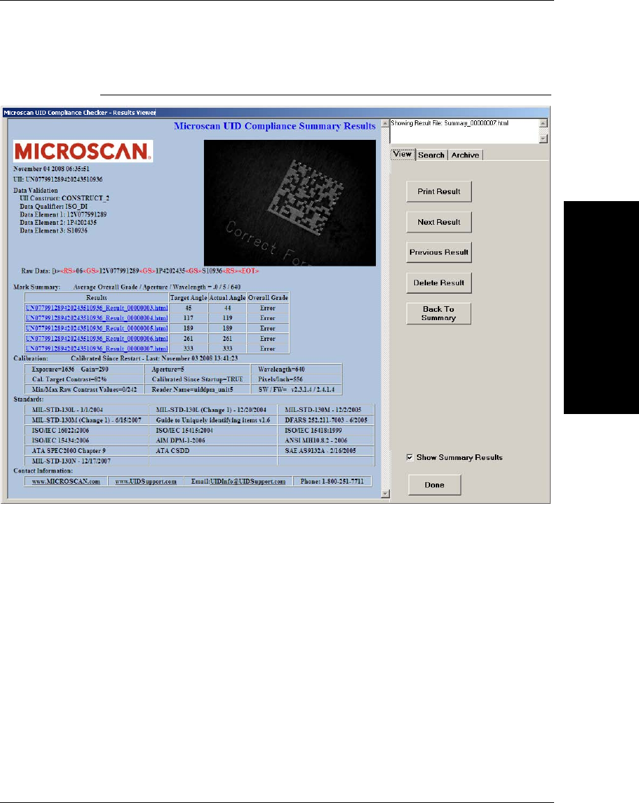
Main Menu Items
UIDChecker™
Application Details
3
v2.3.1, Dec 2008 Getting Started With Your UID Compliance Verifier 3-29
FIGURE 3–23. UID Compliance Verifier Results
The left hand side of this screen is a web browser, which allows viewing of the
saved html files. These results contain a “replaceable” Microscan logo and
uidsupport contact information; the read results Pass/Fail; the UII string, the
detailed read validation and verification results, a picture of the just read UID
mark, the read result number.
The right-hand side of this display has three tabs that allow the user to view the
current results, search through the results for specific strings, and archive the
results.
For the verification type MIL-STD-130M/Change 1 (AIM DPM-1-2006 for
DPM) or MIL-STD-130N (AIM DPM-1-2006) with the Report mode set to
Overall Grade for All Lights, you get a summary report listing the verification
results for each enabled light configurations, as shown in Figure 3–24:
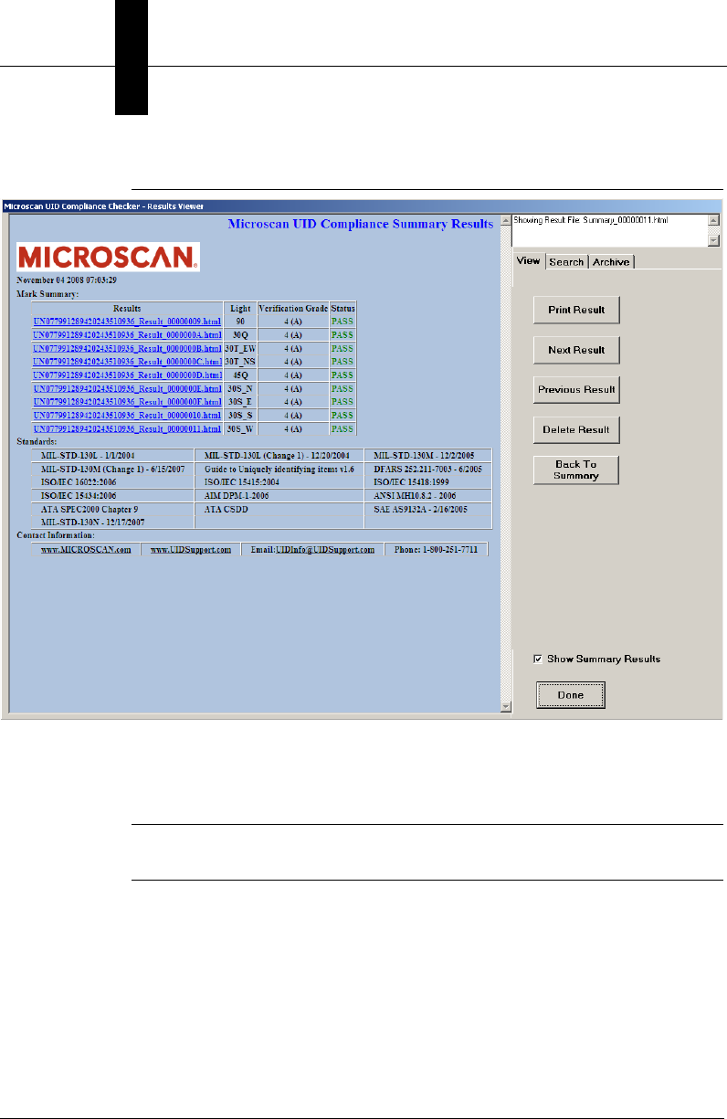
Chapter 3UIDChecker™ Application Details
3-30 Getting Started With Your UID Compliance Verifier v2.3.1, Dec 2008
FIGURE 3–24. Summary Results
You can click on each link to display detailed result record. To go back to the
Summary report from a detailed result record, click the Back to Summary
button.
Note: When in the summary report, the Back to Summary button is still enabled
but clicking on it has no effect.
View Tab
The View Tab allows you to step through and review all of the UIDChecker™
Read results. You can also print and delete these records.
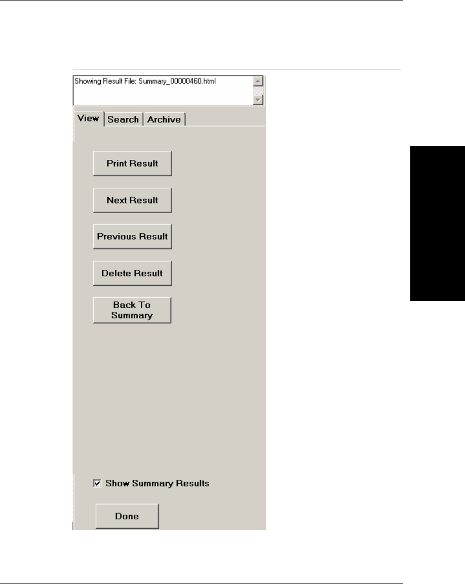
Main Menu Items
UIDChecker™
Application Details
3
v2.3.1, Dec 2008 Getting Started With Your UID Compliance Verifier 3-31
FIGURE 3–25. View Tab

Chapter 3UIDChecker™ Application Details
3-32 Getting Started With Your UID Compliance Verifier v2.3.1, Dec 2008
Print Result
This button allows printing of the current UID Read report to the PC’s default
printer. Print Results couples the last UID Mark read image, compliancy results,
and the customer defined fields on to a one sheet 8 ½” by 11” printout. The user
can then specify his local or network printer. These results contain uidsupport
contact information.
Next Result
This button allows the user to select the next HTML result for viewing. When the
Result Viewer screen is launched, a list of available HTML files is created based
on the files found in the “Results” folder. Clicking Next Result simply opens the
next HTML file in the list.
Previous Result
This button allows the user to select the previous HTML result for viewing.
When the Result Viewer screen is launched, a list of available HTML files is
created based on the files found in the “Results” folder. Clicking Previous
Result simply opens the previous HTML file in the list.
Delete Result
This button allows the user to delete the result currently being viewed. Clicking
this button will cause the HTML file and the image file to be permanently
removed from the system. An “Are You Sure” message box will prompt the user
for confirmation before the result is deleted. When the result is deleted, the
UIDDataLog.Dat file is modified to no longer contain the text for the deleted
result.
Show Summary Results
When checked, Show Summary Results displays the summary results in the
Verification report. When not checked, the verification results for each individual
light configuration is displayed.
Done
This button returns the user to the main screen.
Search Tab
The following information describes the fields and buttons found on the Search
Tab.
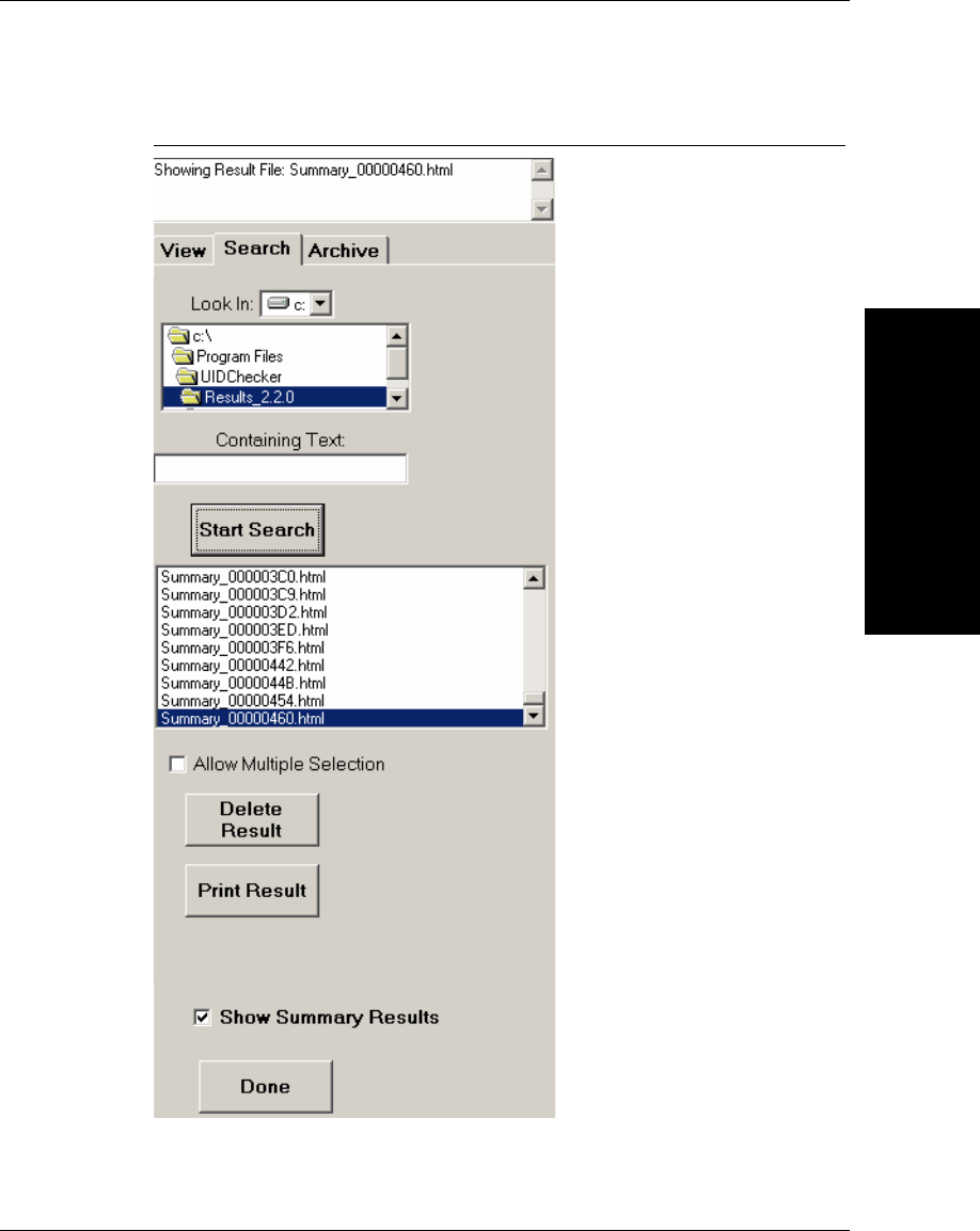
Main Menu Items
UIDChecker™
Application Details
3
v2.3.1, Dec 2008 Getting Started With Your UID Compliance Verifier 3-33
FIGURE 3–26. Search Tab

Chapter 3UIDChecker™ Application Details
3-34 Getting Started With Your UID Compliance Verifier v2.3.1, Dec 2008
Look In
The location for searching can be set using the “Drive” selector and “Path”
selector at the top of the Search Tab.
Containing Text
This text box is where you enter the text that will be searched for. If left blank, all
HTML files in the selected folder will be listed in the result list box. You can use
the wildcard character “*” in your searches.
Start Search
This button initiates the search in the selected folder. Alternately, clicking on a
folder in the “Path” control will initiate a search.
Result List Box
This list displays all of the HTML files that are found in the selected folder.
When the Containing Text field is used, the list contains only those HTML files
that contain the specified text.
Allow Multiple Selection
When this check box is not checked, clicking on a result in the Result List box
causes that result to be displayed. When this box is checked, multiple results may
be selected. Clicking on a result in the Result List box will not cause that result to
be displayed.
Delete Result
When this button is clicked, the selected result or list of results is deleted from
the system.
Print Result
This button allows printing of the result data currently shown.
Archive Tab
The following information describes the fields and buttons found on the Archive
Tab.
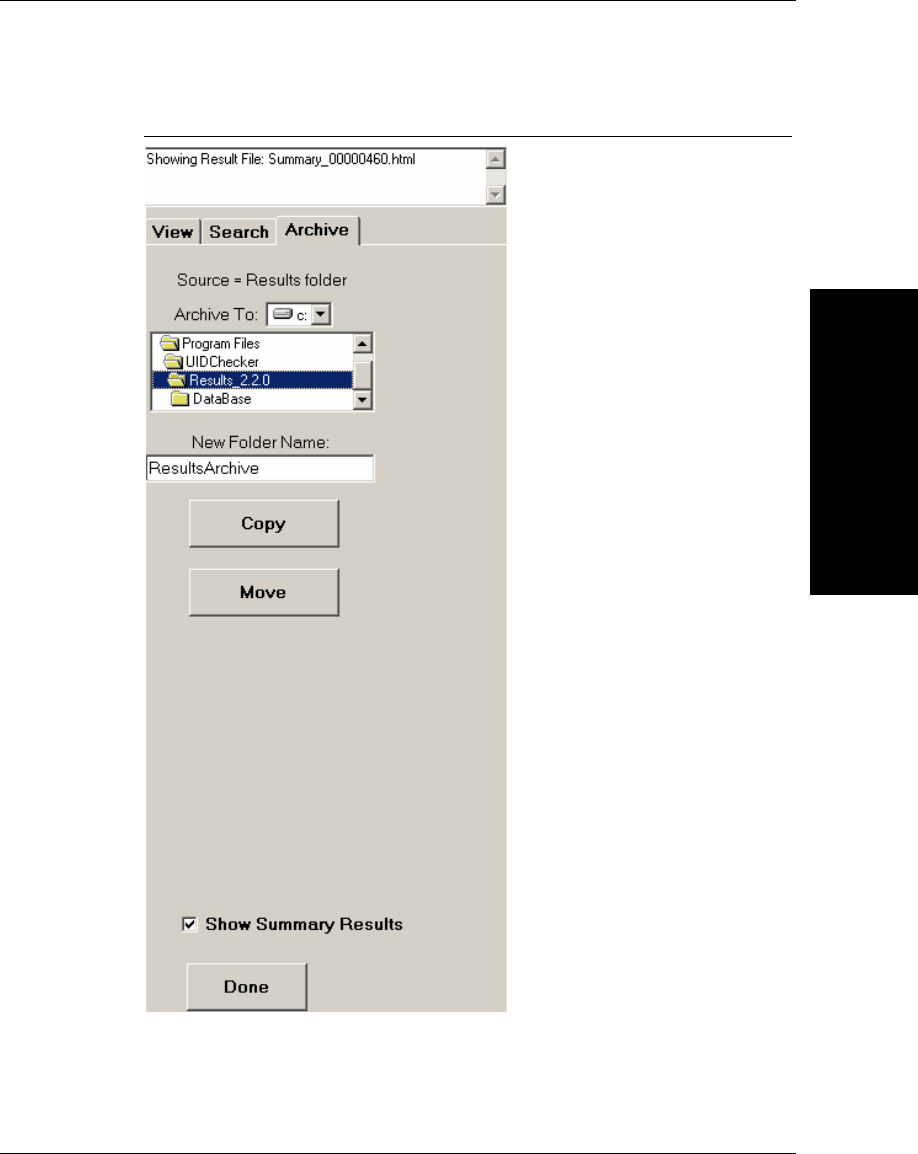
Main Menu Items
UIDChecker™
Application Details
3
v2.3.1, Dec 2008 Getting Started With Your UID Compliance Verifier 3-35
FIGURE 3–27. Archive Tab
Archive To
The location to which result files are to be archived can be set using the “Drive”
selector and “Path” selector at the top of the Search Tab.

Chapter 3UIDChecker™ Application Details
3-36 Getting Started With Your UID Compliance Verifier v2.3.1, Dec 2008
New Folder Name
This text box allows the user to enter a name of a folder to archive into. If left
blank, the UIDChecker™ software uses the name “ResultsArchive” for the folder
name.
Copy
This button allows the user to copy all of the results in the UIDChecker\Results
folder to the folder specified in the Archive To and New Folder Name settings.
When duplicate files exist, the UIDChecker™ software will ask if it is OK to
overwrite existing result files. When this operation is complete, the
UIDChecker\Results folder will still contain the result files.
Move
This button allows the user to move all of the results in the UIDChecker\Results
folder to the folder specified in the Archive To and New Folder Name settings.
When duplicate files exist, the UIDChecker™ software will ask if it is OK to
overwrite existing result files. When this operation is complete, the
UIDChecker\Results folder will no longer contain any files.
About
View details about the UIDChecker™ application program and our contact data.
The About box displays the current software version and build number, as well as
providing the Customer Service phone number, a link to the Microscan website,
and a link to the UIDSupport website. The About box also displays all teh
standards supported by the software.
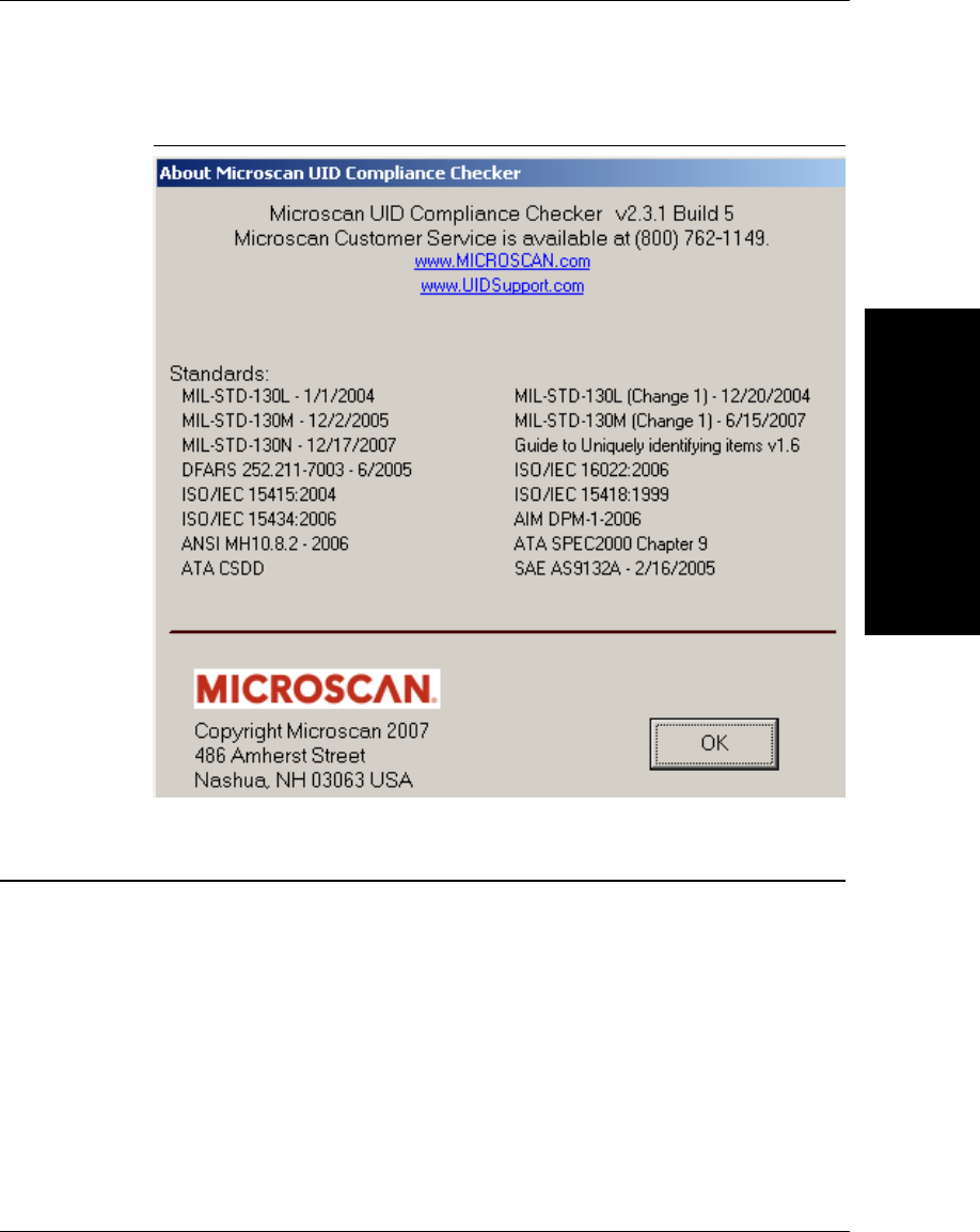
UIDChecker™ UID Mark Validation Error Messages
UIDChecker™
Application Details
3
v2.3.1, Dec 2008 Getting Started With Your UID Compliance Verifier 3-37
FIGURE 3–28. About Box
UIDChecker™ UID Mark Validation Error Messages
UIDChecker™ reports a description of the first error it encountered trying to
decode the UID mark. This should help you debug your marking application.
Table 3–1 is a list of potential errors generated and some suggestions for how to
correct your failing UID mark.
Chapter 3UIDChecker™ Application Details
3-38 Getting Started With Your UID Compliance Verifier v2.3.1, Dec 2008
TABLE 3–1. UII Error Codes
UII Error Code Suggestion to Correct Problem
240 ERROR - CHARACTER The current part number’s data element character
is either missing or has wrong semantics
240 ERROR - TOO LONG The current part number is too long
240 ERROR - TOO SHORT The current part number is too short
30P ERROR - CHARACTER The current part number’s data element character
is either missing or has wrong semantics
30P ERROR - TOO LONG The current part number is too long
30P ERROR - TOO SHORT The current part number is too short
30T ERROR - CHARACTER The lot/batch number’s data element character is
either missing or has wrong semantics
30T ERROR - TOO LONG The lot/batch number is too long
30T ERROR - TOO SHORT The lot/batch number is too short
DATA ELEMENT CHARACTER The data element character is either missing or
wrong semantics
DATA ELEMENT SEPARATOR The data element separator is either missing or
wrong semantics
DATA ELEMENT TOO LONG The data element character is too long
DATA ELEMENT TOO SHORT The data element character is too short
DOUBLE TRAILER Remove one trailer at the end
FORMAT INDICATOR ERROR Correct the Format Indicator (05, 06, DD, or 12)
HEADER 1ST POSITION Correct the error in the 1st position of the header;
The Mark does not appear to be a UID Mark.
HEADER 2ND POSITION Correct the error in the 2nd position of the header
HEADER 3RD POSITION Correct the error in the 3rd position of the header
HEADER 4TH POSITION Correct the error in the 4th position of the header
HEADER GROUP SEPARATOR GS is needed right after the Format Indicator
LOWER CASE CHARACTER A lower case character was found, replace with
an Upper case character.
NEED UII ELEMENT FIRST The UII element is not at beginning of the data
elements
PNR ERROR - CHARACTER The current part number’s data element character
is either missing or has wrong semantics
UIDChecker™ Data Matrix Verification Error Messages
UIDChecker™
Application Details
3
v2.3.1, Dec 2008 Getting Started With Your UID Compliance Verifier 3-39
UIDChecker™ Data Matrix Verification Error Messages
UIDChecker™ reports the following locate/decode, and verification error
messages.
PNR ERROR - TOO LONG The current part number is too long
PNR ERROR - TOO SHORT The current part number is too short
SPACE AFTER TEI DATA QUALIFIER The TEI space is either missing or wrong
semantics
TEI DATA CHARACTER The TEI character is either missing or wrong
semantics
TEI DATA QUALIFIER The TEI data qualifier is either missing or wrong
semantics
TRAILER - END OF TRANSMISSION The trailer EOT is either missing or wrong syntax
TRAILER - RECORD SEPARATOR The trailer RS is either missing or wrong syntax
UII ELEMENT INCOMPLETE There is an incomplete UII element
UII STRING TOO LONG The UII string is over 50-character limit
WRONG FORMAT INDICATOR Correct the Format Indicator (05, 06, DD, or 12)
TABLE 3–2. Data Matrix Locate/Decode Error Codes
Locate/Decode Error Reason
No edge candidate found Cannot find the any acceptable edges
First edge not found Cannot determine the first border
Second edge not found Cannot determine the second border
Third edge not found Cannot determine the third border
Fourth edge not found Cannot determine the fourth border
Four corners not found Cannot determine all four corners
Size varying too much Severe distortion causes size to vary too much
Row/Column test failed Cannot determine rows or columns
Border match test failed Border quality not acceptable
Unable to decode Failed to decode the Data Matrix
Inspection timeout Timed out in decoding Data Matrix
TABLE 3–1. UII Error Codes (continued)
UII Error Code Suggestion to Correct Problem

Chapter 3UIDChecker™ Application Details
3-40 Getting Started With Your UID Compliance Verifier v2.3.1, Dec 2008
TABLE 3–3. Data Matrix Verification Error Codes
Verification Error Reason
ISO Verification aperture too large Data Matrix cell size is too small for the aperture
05 specified for ISO/IEC 15415
ISO Verification aperture too small Data Matrix cell size is too large for the aperture
05 specified for ISO/IEC 15415
ISO Verification cell size greater than Max X Cell size is greater than Max X specified for AIM
DPM-1-2006.
ISO Verification cell size smaller than Min X Cell size is smaller than Min X specified for AIM
DPM-1-2006.
ISO Verification ECC200 required ECC200 is required for ISO/IEC 15415 or AIM
DPM-1-2006
ISO Verification failed RDA error correction Failed error correction in Reference Decode
Algorithm in ISO/IEC 15415 or AIM DPM-1-2006
ISO Verification failed RDA final image
adjustment Failed the final image adjustment step in AIM
DPM-1-2006
ISO Verification failed RDA STEP A E Failed Reference Decode Algorithm in steps A
through E in ISO/IEC 15415 or AIM DPM-1-2006
ISO Verification failed RDA STEP F 1 Failed Reference Decode Algorithm in step F 1 in
ISO/IEC 15415 or AIM DPM-1-2006
ISO Verification failed RDA STEP F 2 Failed Reference Decode Algorithm in step F 2 in
ISO/IEC 15415 or AIM DPM-1-2006
ISO Verification failed RDA STEP F 3 Failed Reference Decode Algorithm in step F 3 in
ISO/IEC 15415 or AIM DPM-1-2006
ISO Verification insufficient space There is insufficient space surrounding the Data
Matrix for ISO/IEC 15415 or AIM DPM-1-2006.
v2.3.1, Dec 2008 Getting Started With Your UID Compliance Verifier 4-1
4
UID Read Result Data
Details
4
CHAPTER 4 UID Read Result Data Details
In this chapter, you will learn more about examining and managing your UID
Read results. First, the on-screen data presentation will be explained, then the
data log file will be explained. Refer to “View Results” starting on page 3-28 for
an overview of the UID Mark Read Results.
Analyzing the Results of UIDChecker™
If the Data Matrix mark is a valid UID mark and is verified to be of good quality,
then both the Validation and Verification panels at the right of the screen will
become green, as shown in Figure 4–1. The light on top of the unit will also show
green.
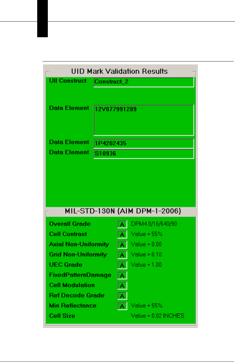
Chapter 4UID Read Result Data Details
4-2 Getting Started With Your UID Compliance Verifier v2.3.1, Dec 2008
FIGURE 4–1. UIDChecker — Passed UII — Good Quality
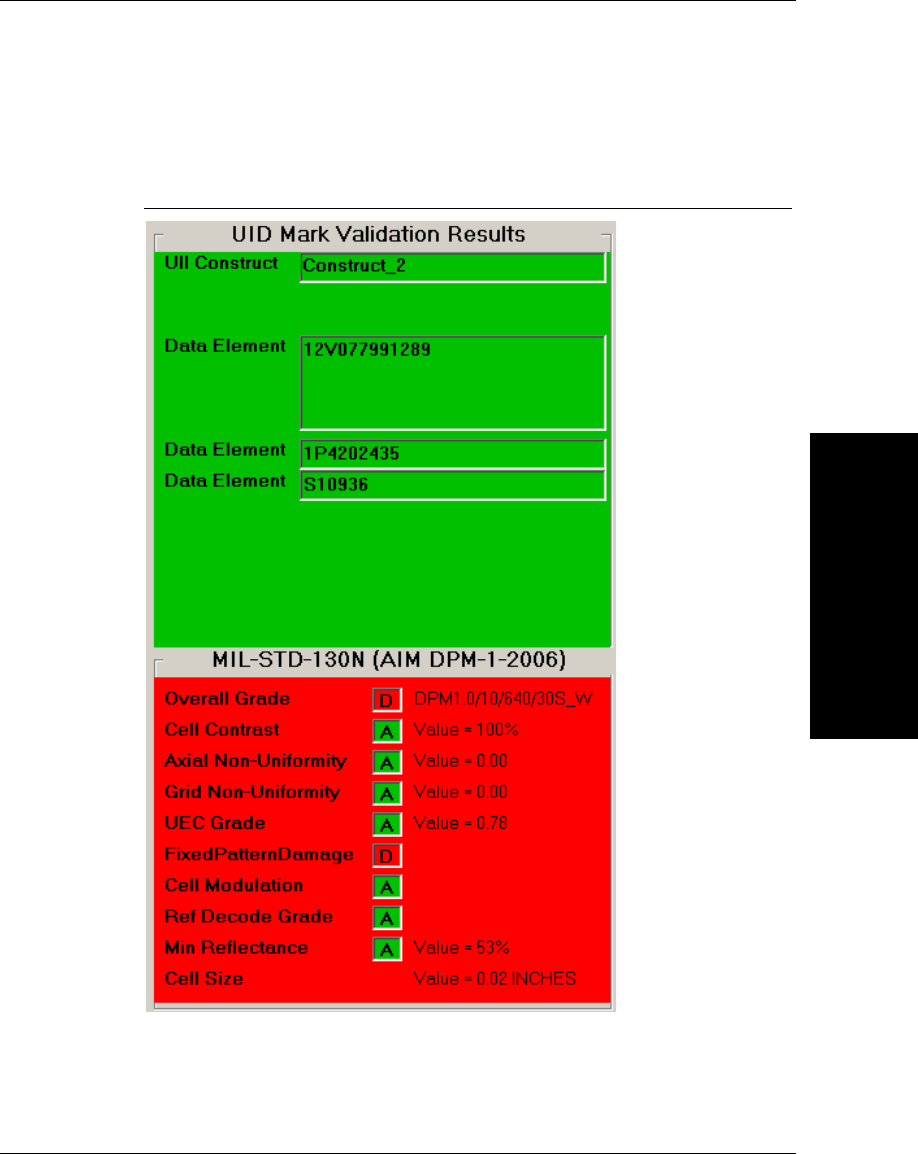
Analyzing the Results of UIDChecker™
UID Read Result Data
Details
4
v2.3.1, Dec 2008 Getting Started With Your UID Compliance Verifier 4-3
If either the validation or the verification test failed, the appropriate panel will be
red, as shown in Figure 4–2. The light on top of the unit will also show red.
FIGURE 4–2. UIDChecker — Passed UII — Bad Quality
If the UID mark is valid, then the validation results panel reports the UID mark
components. As long as the Data Matrix can be decoded and verified, the
verification panel shows the grading on each of the quality tests. The
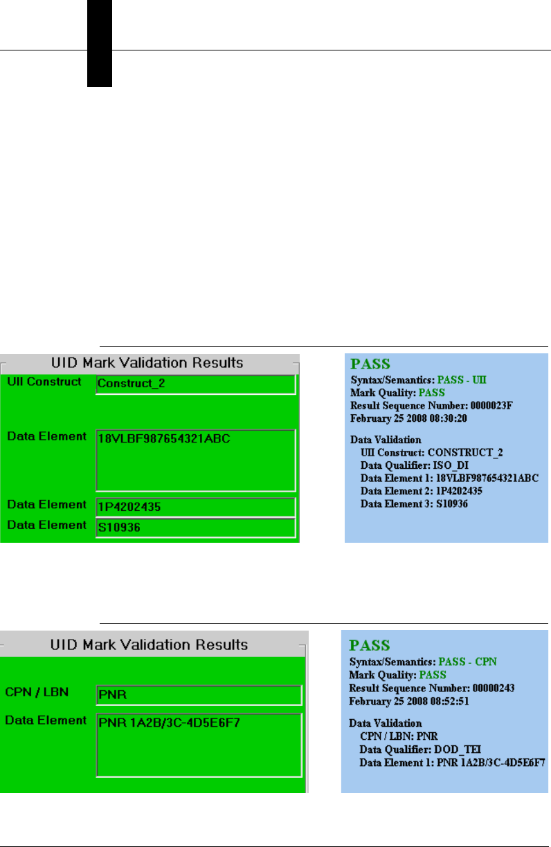
Chapter 4UID Read Result Data Details
4-4 Getting Started With Your UID Compliance Verifier v2.3.1, Dec 2008
UIDChecker™ provides an overall pass/fail using green/red background color
based on the standard you select.
For detailed descriptions of the Data Matrix Verification, please consult the
HawkEye™ 1500 Series Verification Manual.
Figure 4–3 through Figure 4–9 show various possible UII validation results. For
each figure, the on-screen result is shown on the left and the corresponding UID
Read Report is shown on the right.
Figure 4–3 displays the results of a valid UII Data Matrix. Note that the Data
Qualifier is available in the UID Read Report.
FIGURE 4–3. Data Validation — Valid UII
Figure 4–4 displays the results of a valid PNR Data Matrix with the option
“Enable CPN/LBN Support” enabled.
FIGURE 4–4. Data Validation — Valid CPN/LBN
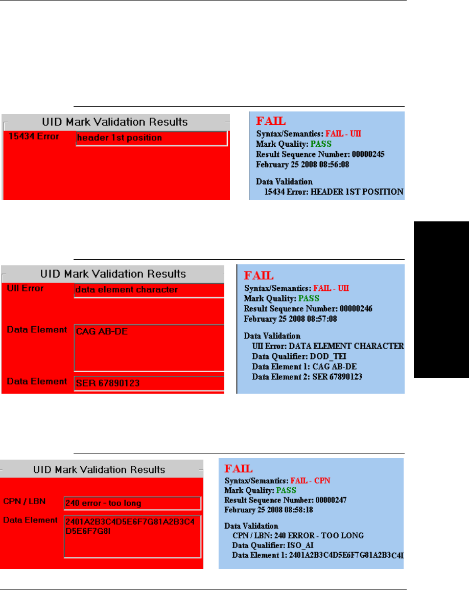
Analyzing the Results of UIDChecker™
UID Read Result Data
Details
4
v2.3.1, Dec 2008 Getting Started With Your UID Compliance Verifier 4-5
Figure 4–5 displays the results of an invalid UII Data Matrix due to an 15434
error.
FIGURE 4–5. Data Validation — 15434 Error in UID Validation
Figure 4–6 displays the results of an invalid UII Data Matrix due to a UII data
element error.
FIGURE 4–6. Data Validation — UII Error in UID Validation
Figure 4–7 displays the results of an invalid 240 Data Matrix with the option
“Enable CPN/LBN Support” checked.
FIGURE 4–7. Data Validation — CPN Error in UID Validation
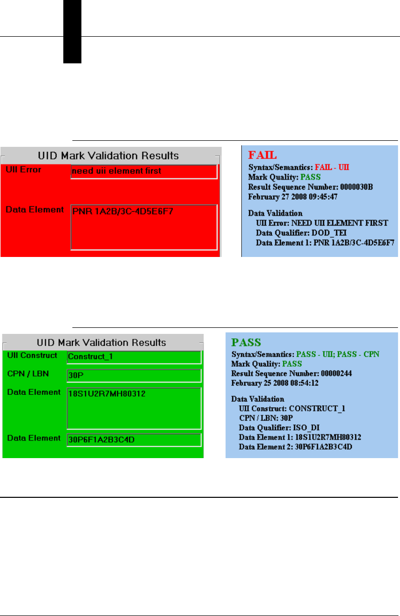
Chapter 4UID Read Result Data Details
4-6 Getting Started With Your UID Compliance Verifier v2.3.1, Dec 2008
Figure 4–8 displays the result of validating a valid PNR Data Matrix without
checking the “Enable CPN/LBN Support” option.
FIGURE 4–8. Data Validation — UII Error for a Valid CPN
Figure 4–9 displays validation results of UII and 30P in the same Data Matrix
when both UII and 30P are valid. Note that “Enable CPN/LBN Support” is
checked.
FIGURE 4–9. Data Validation of UII & 30P in a Single Data Matrix
UID Results Data File
When a read result is saved, the UIDChecker™ software generates a unique
number that gets incorporated into the name of the result and image files. This
number is an 8 digit hexadecimal number starting at the number “00000000”. For
each saved result, this number gets incremented by 1. The last number used gets
stored in the system registry so that, when the UIDChecker™ application is
launched again, the next number to be used can be retrieved from the system
registry.
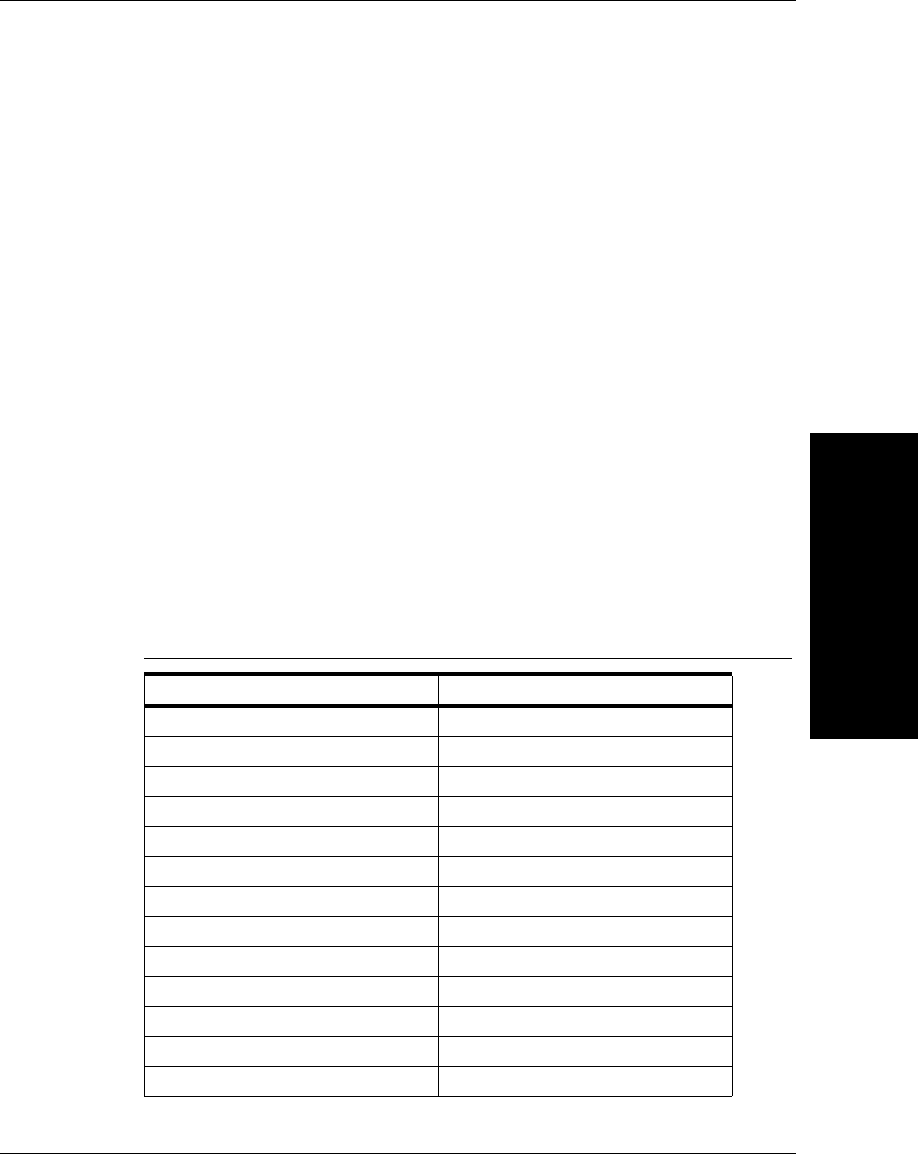
UID Results Data File
UID Read Result Data
Details
4
v2.3.1, Dec 2008 Getting Started With Your UID Compliance Verifier 4-7
Please consult “Store Results in MDB Database and CSV File” on page 3-23 to
enable the writing of UID mark reading results to the CSV file and MDB
database.
Version 2.3 UIDDataLog_2.3.0.csv File Format
The following is a detailed listing of the comma-delimited contents for a version
2.3 data file. Using this description, you should be able to transfer the data into
your local Excel program or a database.
Due to the complexity of parsing rules for the results as presented in the comma-
delimited results file, results are now provided in the same alphabetical order as
in the MDB database record and each field is prefixed with a tag name in the
form “<tag name>,” to make parsing easier. All fields are always written, even if
empty. The following shows the first several fields in the CSV file:
<20xClearSpace>,FALSE,<Angle>,68,<AngleOfDistortionGrade>,,<AngleOfDistortionValue>,,<A
perture>,5,…
Version 2.3 DataBase Table Layout
The database table layout is shown in Table 4–1:
TABLE 4–1. Version 2.3 Database Table Layout
Variable Size
20xClearSpace VarChar(32)
Angle int
AngleOfDistortionGrade VarChar(4)
AngleOfDistortionValue int
Aperture VarChar(8)
AperturePercentage int
AssociatedCpnLbnString VarChar(128)
AssociatedUIIString VarChar(128)
AxialNonUniformityGrade VarChar(4)
AxialNonUniformityValue Double
CalBlackOffset VarChar(16)
CalExposure int
CalGain int
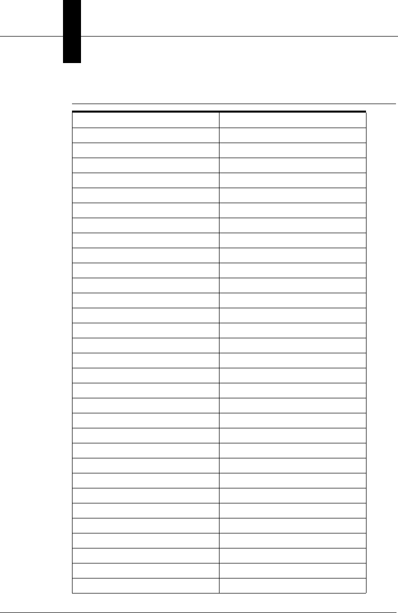
Chapter 4UID Read Result Data Details
4-8 Getting Started With Your UID Compliance Verifier v2.3.1, Dec 2008
Calibrated VarChar(64)
CalibratedSinceStartup VarChar(64)
CalMeanLight int
CalTargetContrast int
CalTargetReflectanceMax int
CellSizeError VarChar(16)
CellSizeGrade VarChar(4)
CellSizeValue Double
CellUnitReportString VarChar(8)
Construct VarChar(32)
ContrastGrade VarChar(4)
ContrastReportString VarChar(32)
ContrastValue int
ConvertImagesToJPG VarChar(8)
CurrentLight VarChar(32)
CurvedPart VarChar(8)
CustomerFields1 VarChar(132)
CustomerFields2 VarChar(132)
CustomerFields3 VarChar(132)
CustomerFields4 VarChar(132)
CustomerFields5 VarChar(132)
DataElement1 VarChar(64)
DataElement2 VarChar(64)
DataElement3 VarChar(64)
DataElement4 VarChar(64)
DataElement5 VarChar(64)
DataElement6 VarChar(64)
DataElement7 VarChar(64)
DataQualifier VarChar(64)
DotCenterOffsetGrade VarChar(4)
DotCenterOffsetValue int
TABLE 4–1. Version 2.3 Database Table Layout (continued)
Variable Size
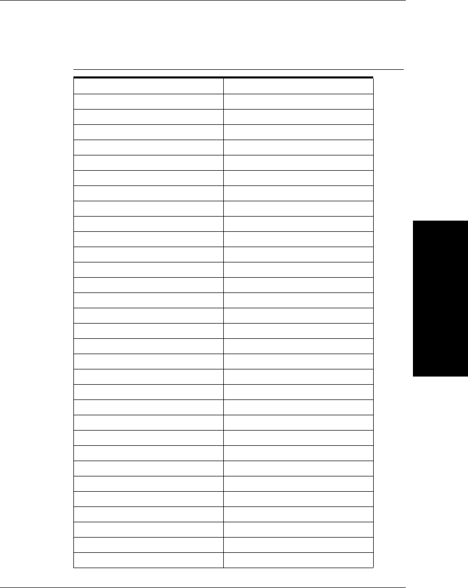
UID Results Data File
UID Read Result Data
Details
4
v2.3.1, Dec 2008 Getting Started With Your UID Compliance Verifier 4-9
DotSizeOffsetGrade VarChar(4)
DotSizeOffsetValue int
ECCLevel VarChar(8)
EditUIIforCpnLbn VarChar(8)
EnableCpnLbnSupport VarChar(8)
Exposure int
FirmwareRev VarChar(12)
FixedPatternDamageGrade VarChar(4)
Gain int
GridNonUniformityGrade VarChar(4)
GridNonUniformityValue Double
HTMLFileName VarChar(255)
ImgFileName VarChar(255)
LastUIIString VarChar(128)
Logo VarChar(255)
MatrixHeightValue Double
MatrixSizeError VarChar(16)
MatrixSizeGrade VarChar(4)
MatrixWidthValue Double
MaxRawContrastValue int
MeanLight int
MinRawContrastValue int
MinReflectanceGrade VarChar(4)
MinReflectanceValue int
ModulationGrade VarChar(4)
ModuleFillGrade VarChar(4)
ModuleFillXValue int
ModuleFillYValue int
NominalModuleSizeGrade VarChar(4)
NominalModuleSizeValue Double
OvalityGrade VarChar(4)
TABLE 4–1. Version 2.3 Database Table Layout (continued)
Variable Size

Chapter 4UID Read Result Data Details
4-10 Getting Started With Your UID Compliance Verifier v2.3.1, Dec 2008
OvalityValue int
OverallGrade VarChar(4)
OverrideCellSize VarChar(8)
PixelsPerInch int
PrintGrowthGrade VarChar(4)
PrintGrowthXValue int
PrintGrowthYValue int
RawData VarChar(255)
ReaderName VarChar(32)
ReferenceDecodeGrade VarChar(4)
SecureCamera VarChar(8)
SequenceNumber VarChar(12)
SoftwareRev VarChar(12)
TimeofLastResult date
UnusedErrorCorrectionGrade VarChar(4)
UnusedErrorCorrectionValue Double
Valid240Pass VarChar(8)
Valid30PPass VarChar(8)
Valid30TPass VarChar(8)
ValidAndVerifPass VarChar(8)
ValidateFailure VarChar(128)
ValidISO15434Pass VarChar(8)
ValidPNRPass VarChar(8)
ValidUIIPass VarChar(8)
VerificationPass VarChar(8)
VerificationType VarChar(64)
VerifyFailure VarChar(128)
VerifyReadPass VarChar(8)
Wavelength int
XDimensionMax int
XDimensionMin int
TABLE 4–1. Version 2.3 Database Table Layout (continued)
Variable Size
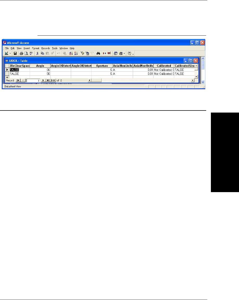
Understanding UID Mark Quality
UID Read Result Data
Details
4
v2.3.1, Dec 2008 Getting Started With Your UID Compliance Verifier 4-11
FIGURE 4–10. Microsoft Access View
Understanding UID Mark Quality
Data Matrix Cell Size
The UIDChecker™ has been configured to read marks of the size range that is
specified by revisions L, L Change 1, M, and M Change 1 of MIL-STD-130.
These marks with cell sizes in the 0.0075 to 0.025 inch range can be decode
reliably and verified by the UIDChecker™ using UID-LDP and UID-DPM.
Microscan can’t guarantee reliable performance of the standard UID-LDP and
UID-DPM on marks with cell sizes outside this range. For applications outside
this range, please contact Microscan for special hardware setup and application
support.
ECC 200
The UIDChecker™ has been configured to read UID marks made with ECC 200.
If a UID mark does not use ECC200, it is not a valid UID mark and the
UIDChecker™ will fail the validation of the UID mark.
Data Matrix Quality Verification Standard
All supported verification standards are explained in detail in the HawkEye™
1500 Series Verification Manual.

Chapter 4UID Read Result Data Details
4-12 Getting Started With Your UID Compliance Verifier v2.3.1, Dec 2008

v2.3.1, Dec 2008 Getting Started With Your UID Compliance Verifier A-1
A
Upgrading to
UIDChecker™ V2.1
A
APPENDIX A Upgrading to UIDChecker™
V2.1
If the version of your UIDChecker is older than Version 2.1, please follow this
appendix to upgrade to Version 2.1 first. Then, you can follow “Upgrading the
UIDChecker™ Software from V2.1” on page 1-13 to upgrade to the latest
UIDChecker™ Version 2.2.
With Version 2.1 of the UIDChecker™, a DPM Verification License and
UID-CK license are required on the UID-CK hardware. A check occurs at
UIDChecker™ startup to ensure that the DPM Verification License and UID-CK
license are present on the camera. If you have version 2.1 or later UID-CK, your
unit has been pre-configured at the factory for these license keys.
If you are a current user of a v2.0 (or previous) UID-CK, you must perform
several steps to upgrade to v2.1. Contact Microscan to get a document with all
the steps for upgrading, including assigning your verification and UID licenses
keys. After confirming you as a customer, Microscan will e-mail you the
software key and instructions to perform the upgrade to V2.1. An overview of the
upgrade instructions are shown below. Refer to the document that accompanies
your software keys for the latest directions.
1. Launch ReadRunner from the Start Menu
(Start > All Programs > ReadRunner 2.2 > ReadRunner).
2. Take control of your UID-CK.
3. Open the terminal window and type:

Appendix AUpgrading to UIDChecker™ V2.1
A-2 Getting Started With Your UID Compliance Verifier v2.3.1, Dec 2008
Set_license {Microscan provided software license Key}
We advise you to “cut & paste” the software key from this e-mail into the
ReadRunner utility to set the license.
After setting the license keys, you can now install the UID-CK software.
Put the software installation disk into your PC’s CD drive and run Setup. The
automated program will prompt you to:
1. Uninstall the older version of UIDChecker™ software. Just follow the
prompts and click OK.
Note: It will not delete your results!
2. Uninstall the older version of HawkEye’s ReadRunner - this is the code that
talks to the UID-CK unit. Again, just follow the prompts and click OK.
3. Install the new version of HawkEye’s ReadRunner. Just follow the prompts
and click OK.
4. Install the UIDChecker™ software. Just follow the prompts and click OK.
Before using the UIDChecker™ software, you need to upgrade the firmware on
the UID-CK unit. Follow these directions to upgrade the UID-CK unit before you
start the UIDChecker™ software:
1. Install the HawkEye™ software as part of the usual installation process - as
directed above.
2. From the Start Menu, select Programs > ReadRunner 2.2 > Utilities >
Hawkeye Flasher.
The HawkEye Flasher dialog box is displayed, as shown in Figure A–1.
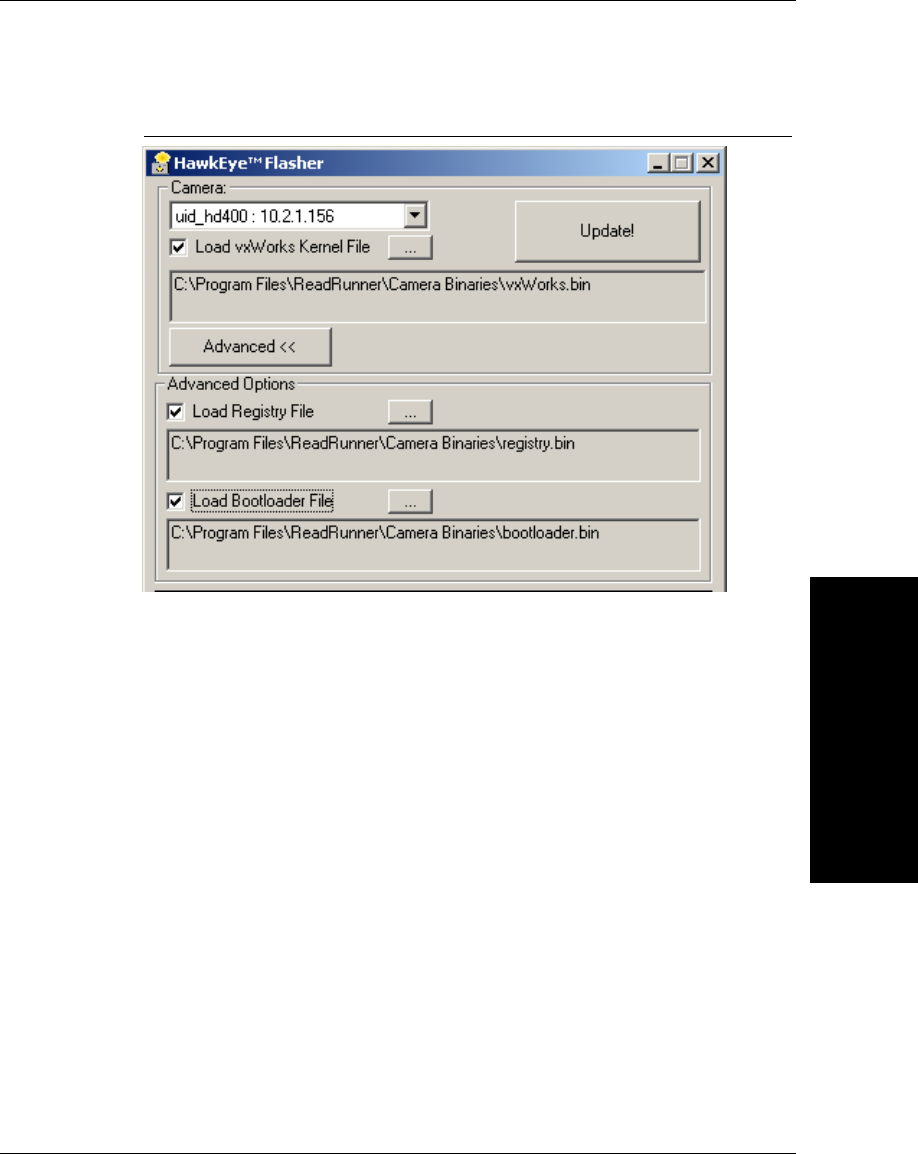
Upgrading to
UIDChecker™ V2.1
A
v2.3.1, Dec 2008 Getting Started With Your UID Compliance Verifier A-3
FIGURE A–1. Upgrade the HawkEye™ Flasher Dialog Box
3. In the drop down list of “Cameras”, select your UID-CK and make sure you
enable (check) all the check boxes for:
– Load VxWorks Kernel
– Load Registry File
– Load Bootloader.
4. Click Update!
When “Done” appears at the bottom of the terminal display, the process is
complete and you can now start the UIDChecker™ software.

Appendix AUpgrading to UIDChecker™ V2.1
A-4 Getting Started With Your UID Compliance Verifier v2.3.1, Dec 2008
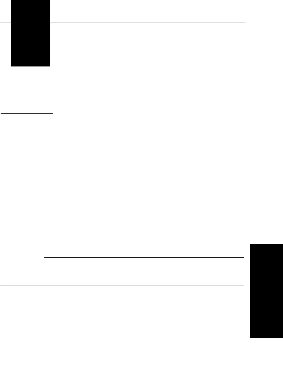
v2.3.1, Dec 2008 Getting Started With Your UID Compliance Verifier B-1
B
Read And Rotate
B
APPENDIX B Read And Rotate
The Read And Rotate button is visible when you select the MIL-STD-130L
Change 1 (ISO/IEC 15415) Verification Type. You use Read And Rotate to
test for rotational consistency of measurements.
Read And Rotate allows you to position your UID Code and read/rotate it five
times at 72° intervals. Use Live Video to position a mark in the FOV of the
reader.
Notes: The Data Matrix must be completely within the screen for a successful
read.
The hardware trigger button is disabled to support Read And Rotate.
Read And Rotate Usage Details
1. Specify the Verification Type to be ISO/IEC 15415 in the Verification
dialog box, as shown Figure B–1.
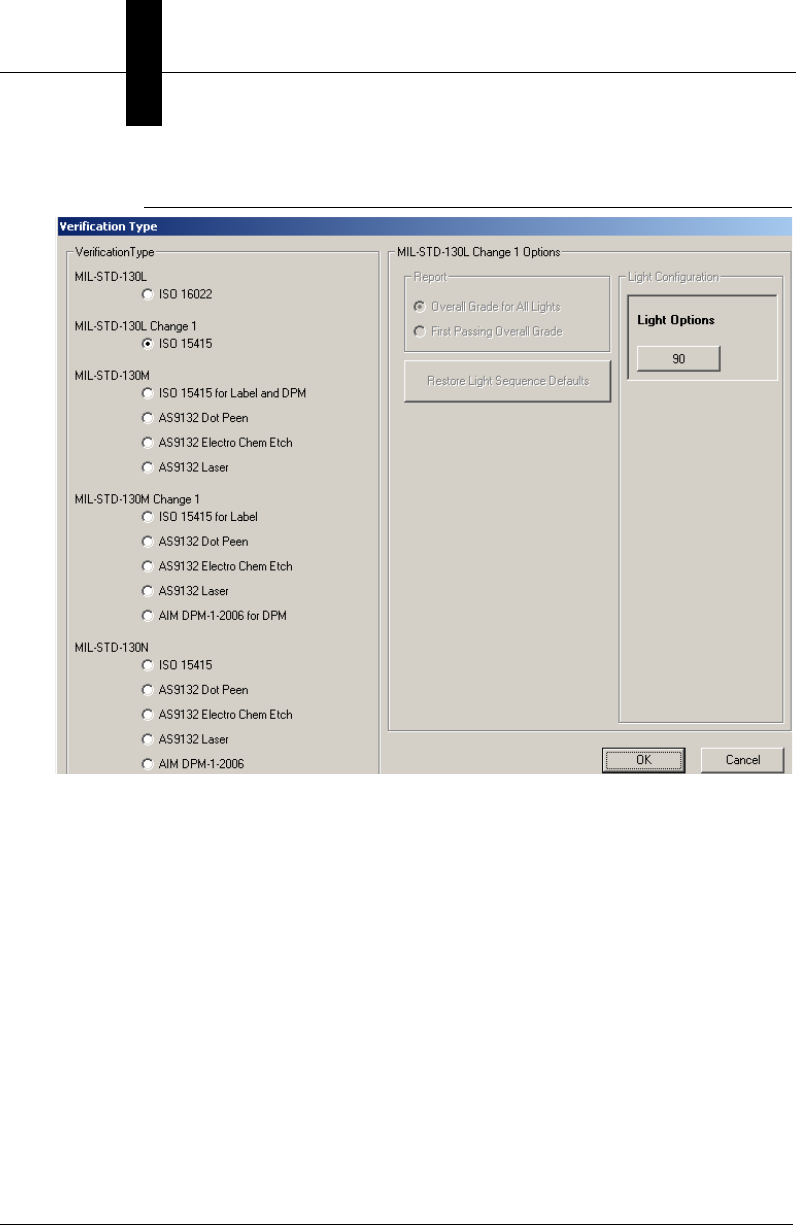
Appendix BRead And Rotate
B-2 Getting Started With Your UID Compliance Verifier v2.3.1, Dec 2008
FIGURE B–1. Setting Verification Type to Invoke Read And Rotate
2. Click OK. The Read And Rotate button will appear on the main interface.
3. Click Read And Rotate. Notice the following:
– The Live Video button is activated.
– The Read And Rotate button becomes the Cancel Read And Rotate
button.
– The chevrons displayed on the main Read And Rotate window
(Figure B–2).
Read And Rotate Usage Details
Read And Rotate
B
v2.3.1, Dec 2008 Getting Started With Your UID Compliance Verifier B-3
FIGURE B–2. Initial Read And Rotate Screen
4. Align the Data Matrix solid edges to the chevron angle. This works best
when you carefully line up the “L” of the Data Matrix as close to the on-
screen “Chevron Angle,” as shown in Figure B–3.
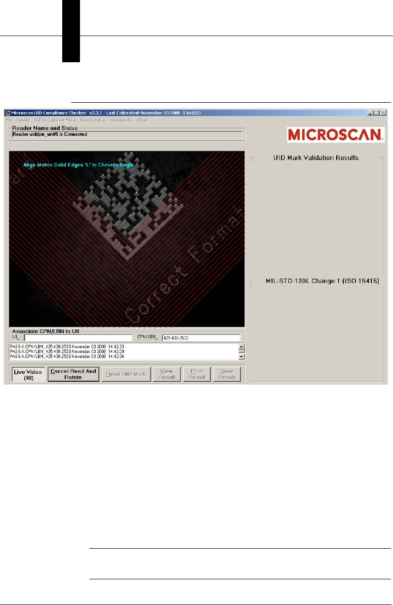
Appendix BRead And Rotate
B-4 Getting Started With Your UID Compliance Verifier v2.3.1, Dec 2008
FIGURE B–3. Read And Rotate First Read
5. After you have the Data Matrix in position, click Live Video.
If the Data Matrix is aligned correctly, the unit beeps and the chevrons are
rotated 72°.
6. Align the Data Matrix solid edges to the new chevron angle.
7. After you have the Data Matrix in position, click Live Video.
8. Continue this process three more times, aligning the Data Matrix solid edges
to the new chevron angle. When you have aligned the Data Matrix a total of
five times, the Live Video button is no longer active (depressed), and a
screen similar to the one in Figure B–4 is displayed.
Note: To cancel out of Read And Rotate, click the Cancel Read And
Rotate button.
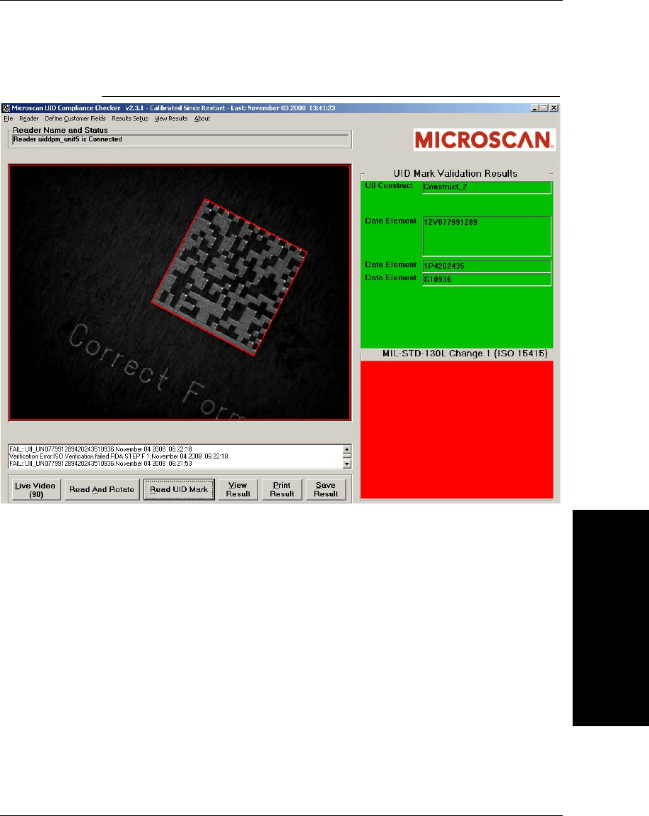
Read And Rotate Usage Details
Read And Rotate
B
v2.3.1, Dec 2008 Getting Started With Your UID Compliance Verifier B-5
FIGURE B–4. Read And Rotate Last Read
9. Save your Results if you have not already done so.
10. Click on View Results to see a Summary Report, if you want to.
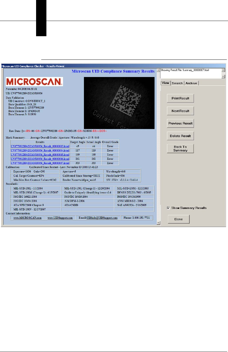
Appendix BRead And Rotate
B-6 Getting Started With Your UID Compliance Verifier v2.3.1, Dec 2008
FIGURE B–5. Read And Rotate Summary Report
Clicking on any of the file names in the table will take you to the individual read
results for the five successful read and verifications.
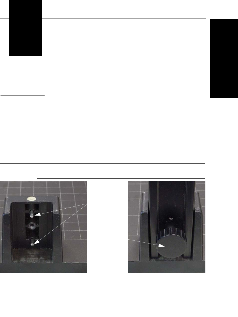
v2.3.1, Dec 2008 Getting Started With Your UID Compliance Verifier C-1
C
Attaching UID-DPM to
UID-DPM Stand
C
APPENDIX C Attaching UID-DPM to
UID-DPM Stand
Setting Up the UID-DPM Stand
FIGURE C–1. Dowel Pins & Thumb Screw
1. Remove the stand base and upright arm from the packaging.
2. Place the base on a level flat surface.
3. Slide the upright arm onto the two dowel pins in the back of the base.
Dowel
Pins
Thumb
Screw
Appendix CAttaching UID-DPM to UID-DPM Stand
C-2 Getting Started With Your UID Compliance Verifier v2.3.1, Dec 2008
4. Fasten the upright arm using the large thumb-screw provided with the kit.
5. Be careful while moving the upright arm. The camera mounting head is
spring-loaded and can move while carrying the arm.
Attaching the UID-DPM
Use the following procedure to attach the UID-DPM to the UID-DPM stand:
1. Rotate the arm so that it is in the position shown in Figure C–2.
FIGURE C–2. Correct Position of Arm
2. Move the bolt on the arm to the correct position before you try to attach the
UID-DPM (see Figure C–3).
Attaching the UID-DPM
Attaching UID-DPM to
UID-DPM Stand
C
v2.3.1, Dec 2008 Getting Started With Your UID Compliance Verifier C-3
FIGURE C–3. Move Bolt to Correct Position
3. Attach the UID-DPM, making sure that all four feet fully contact the base of
the UID-DPM stand.
4. Using one foot of the UID-DPM, set up the correct stand-off distance for the
direct part mark you want to verify, as shown in Figure C–4.
FIGURE C–4. Setting Up Correct Stand-Off Distance
5. Slide the part into the FOV, as shown in Figure C–5.
Move the bolt to this
position before you
attach the UID-DPM

v2.3.1, Dec 2008 Getting Started With Your UID Compliance Verifier D-1
D
Upgrading UID-
DPM001
D
APPENDIX D Upgrading UID-DPM001
w/UIDChecker Software V2.3
Before you upgrade your UID DPM Compliance Kit (UID-DPM001), make sure
you have the following parts.
1. HawkEye 1510 camera with serial cable (FIS-HE15-0CS0)
2. AC power cable for camera (P/N HEPS-1500)
3. DOAL-50 V2, R(660) LED-D
4. AC power cable for light (P/N CPS-12 )
5. DOAL-50 mounting hardware HELTMA-4L (98-LG17-0XX0)
6. C-mount lens 25mm (P/N 928-0057-4) or 35mm (P/N 928-0057-5)
7. Extension ring (P/N C0206)
8. UID stand (98-UA10-0ST0)
9. Ethernet cable (P/N HEENET-007)
10. Thumb screws (4) to attach light mount to the camera (P/N 972-0282-1)
11. Calibration Test Card (98-UA10-0CC0)
12. UID Checker software CD (P/N A1-40266-1V230)
Appendix DUpgrading UID-DPM001 w/UIDChecker Software V2.3
D-2 Getting Started With Your UID Compliance Verifier v2.3.1, Dec 2008
13. Ethernet crossover adapter (P/N HEENET-XLA)
14. Spiral wire wrap (P/N 966-0195-1)
Setting Up the UID-DPM Stand
FIGURE D–1. Dowel Pins and Thumb Screw
1. Remove the stand base and upright arm from the packaging.
2. Place the base on a level flat surface.
3. Slide the upright arm onto the two dowel pins in the back of the base.
4. Fasten the upright arm using the large thumb screw provided with the kit.
5. Be careful while moving the upright arm. The camera mounting head is
spring-loaded and can move while carrying the arm.
Attaching the Camera
1. Attach the HawkEye™ 1510 camera to the stand using the ¼-20 thumb
screw that protrudes from the front of the camera mount head.
2. Connect the HEPS-1500 power cable to the camera.
3. Plug the HEPS-1500 power cable into a 110V outlet.
4. Connect the HEENET-007 network cable to the camera.
Dowel
Pins Thumb
Screw
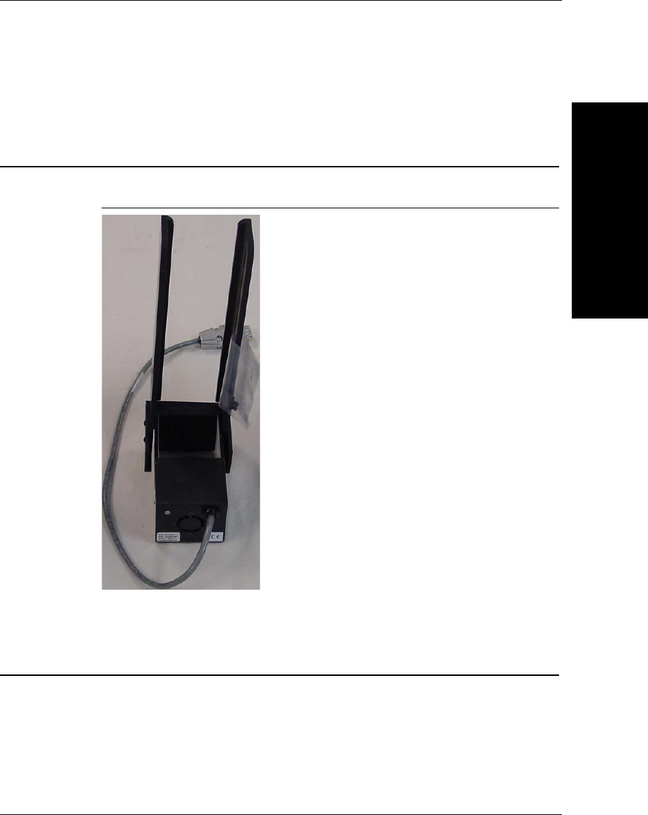
Assembling the Lights
Upgrading UID-
DPM001
D
v2.3.1, Dec 2008 Getting Started With Your UID Compliance Verifier D-3
5. Loop the power and Ethernet cable in the wire hook on the back rear of the
camera mounting head.
Assembling the Lights
FIGURE D–2. HELTMA-4L Bracket
1. Assemble the HELTMA-4L to the DOAL-50 using two M6x10mm screw.
Preparing the Lenses
1. Take the lenses out of their boxes and remove the plastic over-wrap. Store
the lenses with the lens covers on.
2. Remove the extension tubes from the box and remove plastic over-wrap.
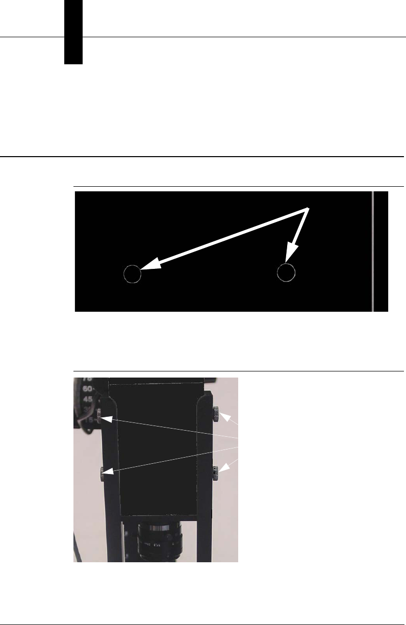
Appendix DUpgrading UID-DPM001 w/UIDChecker Software V2.3
D-4 Getting Started With Your UID Compliance Verifier v2.3.1, Dec 2008
3. Remove the lens protective cap from the bottom of the HawkEye™ 1510
camera.
Attaching the Lights to the Camera
FIGURE D–3. Small Hole Caps
1. Using a small screwdriver, remove the 4 small hole caps (two on each side)
on the sides of the HawkEye™ camera.
FIGURE D–4. Thumb Screws
2. Using the 4 thumb screws provided, attach the HELTMA-4L bracket to the
HawkEye™ camera.
Thumb
Screws

Recommended Verifier Setting with 25mm Lens
Upgrading UID-
DPM001
D
v2.3.1, Dec 2008 Getting Started With Your UID Compliance Verifier D-5
3. Plug the CPS-12 power supply into a 110V outlet and attach the DB-9
connector to the light attached to the HELTMA bracket.
4. Center the light on the camera by loosening the four button head screws on
the side of the HELTMA and centering the light.
Recommended Verifier Setting with 25mm Lens
f-stop = 2
Extension Ring = 6mm
Distance from front of camera to part = 8 inches (203.2 mm)
Distance from bottom of light to part = 2 inches (50.8 mm)
Field of View = 1.19 inches x 0.86 inches (30.2 mm x 21.8 mm)
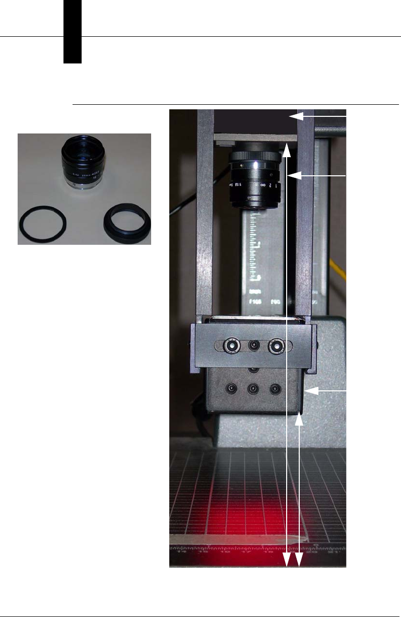
Appendix DUpgrading UID-DPM001 w/UIDChecker Software V2.3
D-6 Getting Started With Your UID Compliance Verifier v2.3.1, Dec 2008
FIGURE D–5. Setting 1 — 25mm Lens with 6mm Extension Ring
DOAL 50
2”8”
HE1510
25mm
1mm 5mm
f-stop=2

Recommended Verifier Setting with 35mm Lens
Upgrading UID-
DPM001
D
v2.3.1, Dec 2008 Getting Started With Your UID Compliance Verifier D-7
Recommended Verifier Setting with 35mm Lens
f-stop = 3
Extension Ring = 10mm
Distance from front of camera to part = 9 inches (228.6 mm)
Distance from bottom of light to part = 2 inches (50.8 mm)
Field of View = 0.89 inches x 0.67 inches (22.6 mm x 17.0 mm)
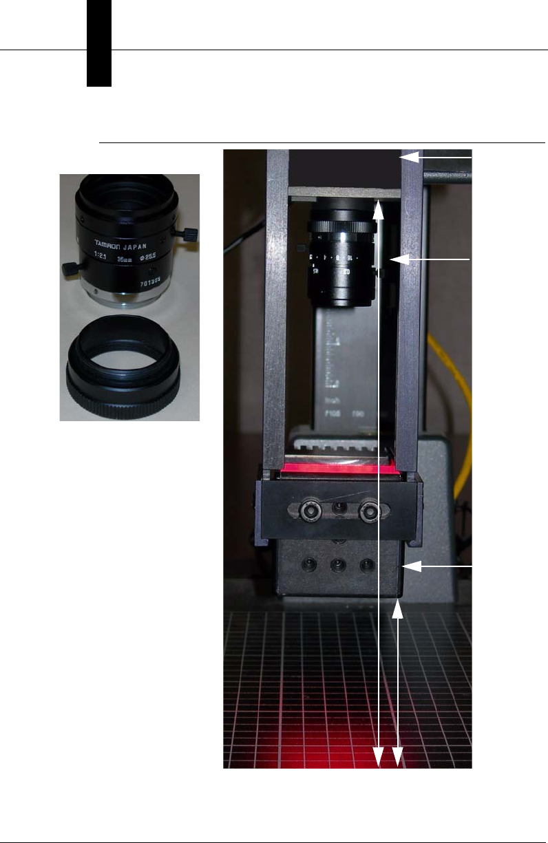
Appendix DUpgrading UID-DPM001 w/UIDChecker Software V2.3
D-8 Getting Started With Your UID Compliance Verifier v2.3.1, Dec 2008
FIGURE D–6. Setting 2 — 35mm Lens with 10mm Extension Ring
2”
9”
DOAL 50
HE1510
35mm
10mm
f-stop=3
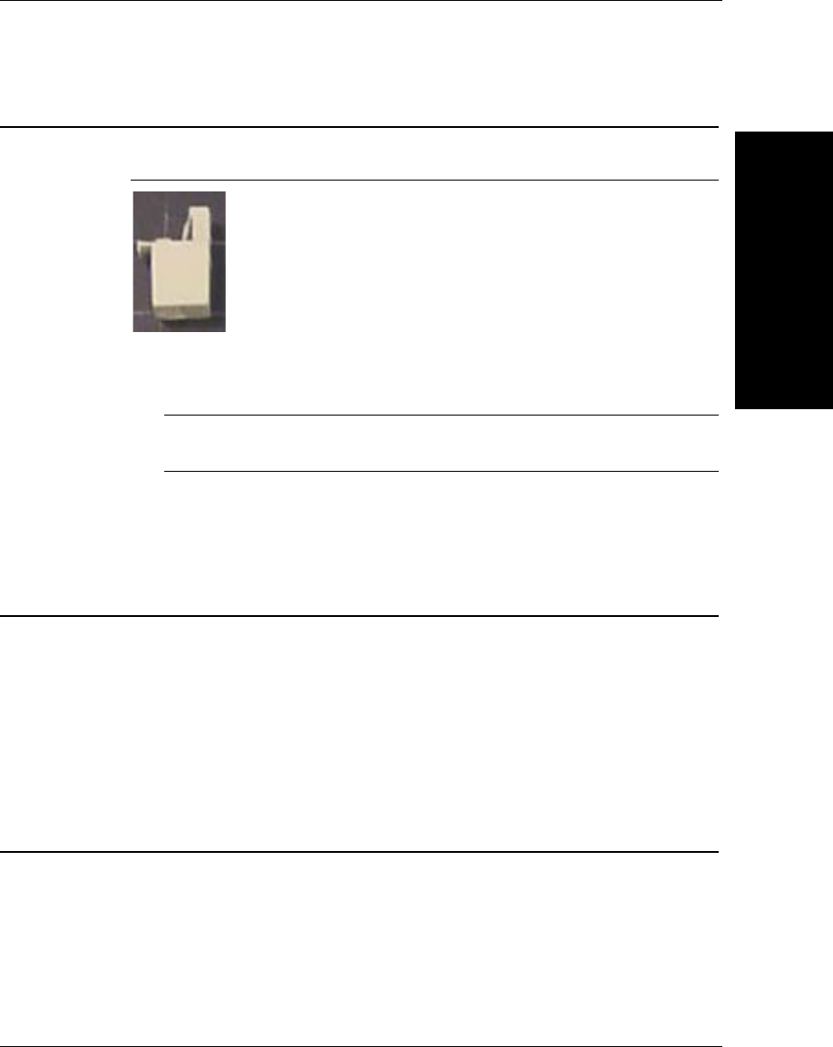
Setting Up the Network
Upgrading UID-
DPM001
D
v2.3.1, Dec 2008 Getting Started With Your UID Compliance Verifier D-9
Setting Up the Network
FIGURE D–7. HEENET-XLA Ethernet Crossover Adapter
1. If you are not using a company LAN or a router between the camera and PC,
you can use the included HEENET-XLA Ethernet crossover adapter.
Note: Do not use the crossover adapter if you are using a router, switch, or
company LAN.
2. Follow “Networking to the UID-LDP & UID-DPM” on page 1-10 for setting
up DHCP or static IP communications between your camera and PC.
Upgrading the Software
1. Configure the hardware to Setting 1 or 2, based on the lens used.
2. Power up the HawkEye 1510 with Ethernet cable and RS-232 serial cable
connected.
3. Install UIDChecker v2.2 to the PC and use the HawkEye_flasher to upgrade
the camera firmware.
Configuring the Verifier
The verifier needs to be configured every time the firmware is updated.
1. Run HyperTerminal and configure the COM port to 115200, 8, Parity None,
Stop bits 1, Flow control None.
2. Select the Connect icon to make the serial connection.

Appendix DUpgrading UID-DPM001 w/UIDChecker Software V2.3
D-10 Getting Started With Your UID Compliance Verifier v2.3.1, Dec 2008
3. Type Ctrl-P to get the prompt >.
4. Type CONTROL.
5. Type XLIGHTCHANNELS 1.
6. For DOAL-50 with wavelength 660nm, type WAVELENGTH 660.
7. Type SAVE BOOT.
8. Type RELEASE.
9. Type Ctrl-P.
10. Click the Disconnect icon to disconnect.
HawkEye Sensor/Lighting Normalization
To normalize the sensor response with respect to the lighting setup, use the
HawkEye Normalization tool:
1. Go to \Program Files\UIDChecker\Utilities.
2. Double click HawkEyeNormalization.exe.
The screen in Figure D–8 is displayed.
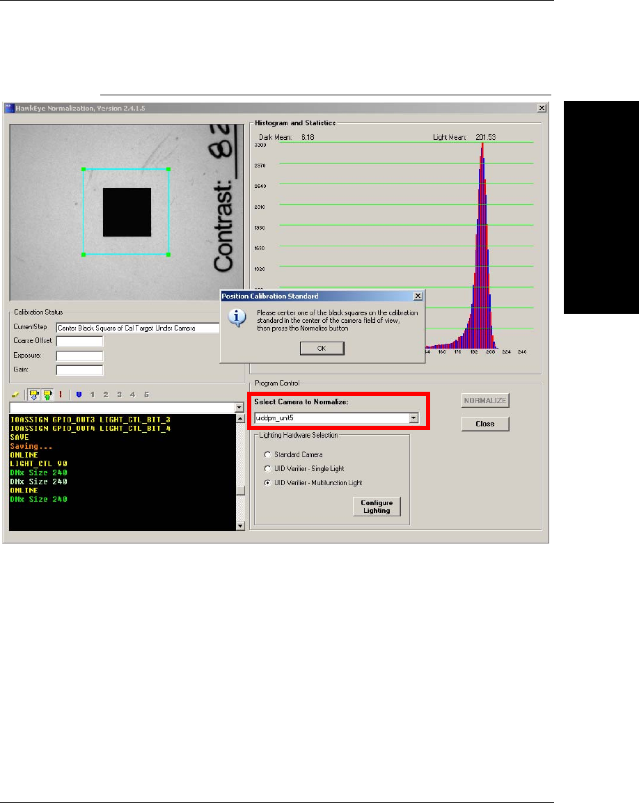
HawkEye Sensor/Lighting Normalization
Upgrading UID-
DPM001
D
v2.3.1, Dec 2008 Getting Started With Your UID Compliance Verifier D-11
FIGURE D–8. HawkEye Normalization Tool
3. In the Select Camera to Normalize drop down list box, select the correct UID
verifier camera or enter the IP address of the camera.
4. Position the Calibration Test Card such that the black square is in the center
of the light blue square. Click OK on the Position Calibration Standard
dialog box. Click NORMALIZE.
For UID Verifier - Multifunction Light, the normalization can take 10
minutes to complete.

Appendix DUpgrading UID-DPM001 w/UIDChecker Software V2.3
D-12 Getting Started With Your UID Compliance Verifier v2.3.1, Dec 2008
Reflectance Calibration
Perform reflectance calibration (see “Perform Reflectance Calibration” on
page 2-3).
You are now ready to use the upgraded verifier system that supports MIL-STD-
130N and AIM DPM-1-2006.
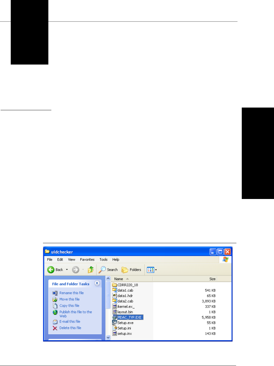
v2.3.1, Dec 2008 Getting Started With Your UID Compliance Verifier E-1
E
Fixing ADO
Components Error
E
APPENDIX E Fixing ADO Components
Error
To fix an ADO components error, the latest version (2.8 sp1) of
MDAC_TYP.EXE from Microsoft has been provided on the UID Compliance
Checker installation disk. Run MDAC_TYP.EXE to update the ADO
components.
These are the components already installed with Windows XP SP2, so it is
unnecessary to update a Windows XP SP2 system.
FIGURE E–1. MDAC_TYP.EXE to Fix ADO Error Under XP
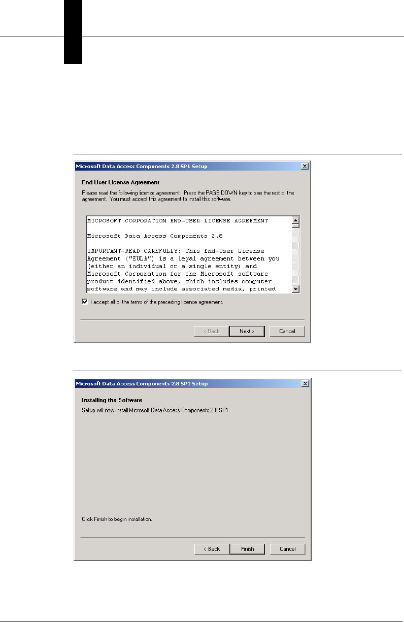
Appendix EFixing ADO Components Error
E-2 Getting Started With Your UID Compliance Verifier v2.3.1, Dec 2008
Under Windows 2000, run the MDAC_TYP.EXE utility to update the ADO
components, and you will see the dialog boxes in Figure E–2, Figure E–3, and
Figure E–4.
FIGURE E–2. Run MDAC_TYP.EXE Under Win2K, Click Next
FIGURE E–3. MDAC_TYP.EXE Fix ADO, Click Finish
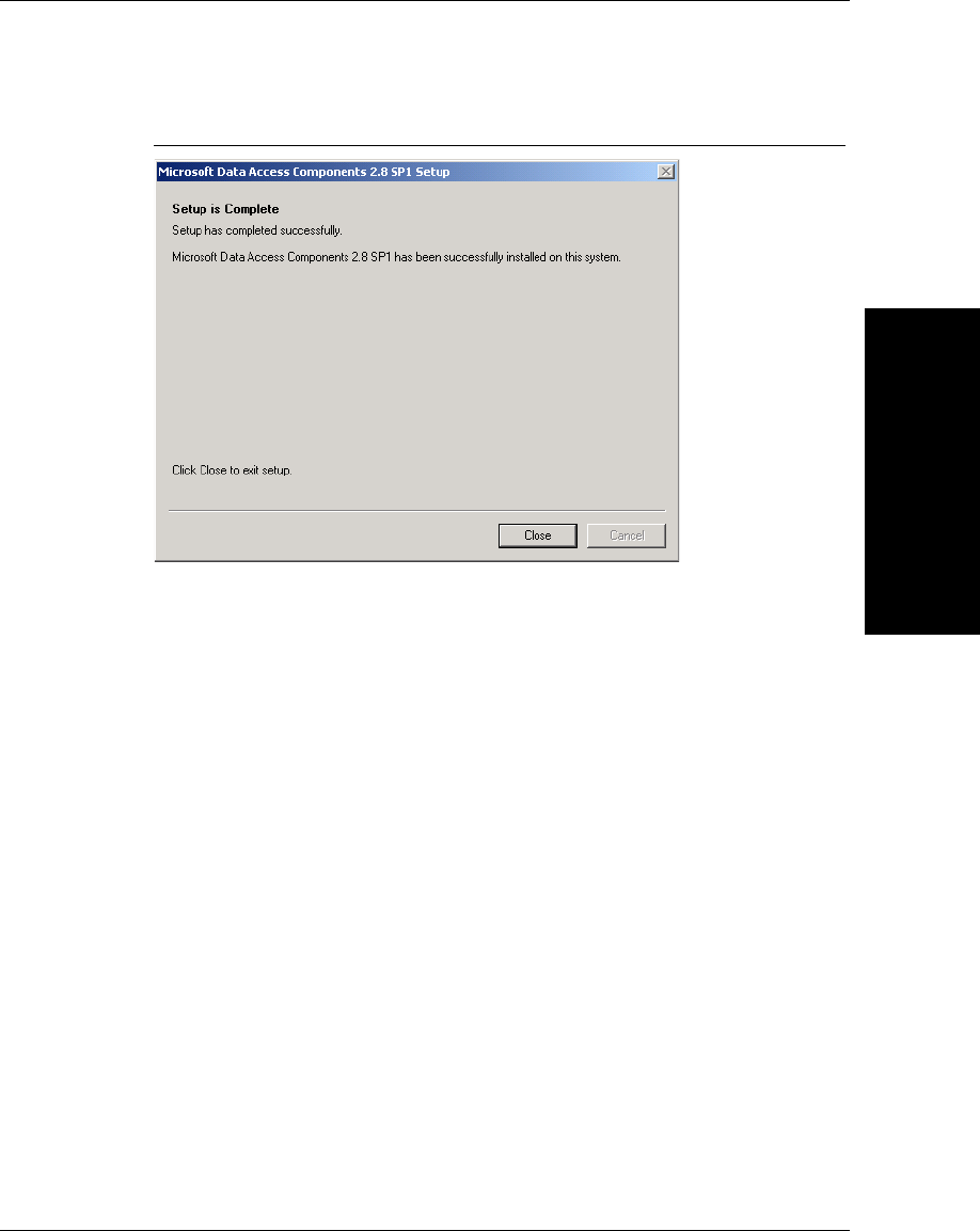
Fixing ADO
Components Error
E
v2.3.1, Dec 2008 Getting Started With Your UID Compliance Verifier E-3
FIGURE E–4. MDAC_TYP.EXE to Fix ADO Error Complete

Appendix EFixing ADO Components Error
E-4 Getting Started With Your UID Compliance Verifier v2.3.1, Dec 2008

v2.3.1, Dec 2008 Getting Started With Your UID Compliance Verifier F-1
F
Data File Formats for
UIDChecker Software
F
APPENDIX F Data File Formats for
UIDChecker Software
For completeness, we will detail the comma-delimited read data log file from
both Version 1 and Version 2 software. In the latest software, with the new
Verifications now supported in the UIDChecker™ software and the enhanced
reporting of the read data, the format of the Results has changed slightly. In
particular, the log file, UIDDataLog.Dat, has changed.
• “Version 1.0 UIDDataLog.Dat File Format” starting on page F-1
• “Version 2.0 UIDDataLog.Dat File Format” starting on page F-4
• “Version 2.1 UIDDataLog.csv File Format” starting on page F-10
• “Version 2.1 DataBase Table Layout” starting on page F-11
• “Version 2.2 DataBase Table Layout” starting on page F-14
Version 1.0 UIDDataLog.Dat File Format
For version 1.0+ users who read this data into a local database, you should
continue to use that format for version 1.0+ files.
The UID Mark data that is read and reported back to the UIDChecker™ user
interface will be saved on the customer’s hard drive in the following format:

Appendix FData File Formats for UIDChecker Software
F-2 Getting Started With Your UID Compliance Verifier v2.3.1, Dec 2008
• HTML files containing the results for a single read. These files contain the
text and image data, allowing for simple viewing in a web browser. HTML
offers a more secure file structure than a typical text file. Editing or changing
data results is more difficult for a novice PC user. HTML file names are the
unique hex number prefixed by “Result_” and suffixed by “.html”.
• Image files are the bitmap image used for the read. Saving image data is a
user-defined option. Image file names are the unique hex number prefixed
by “Image_” and suffixed by “.bmp”.
• The cumulative log file gets appended with the text for each result that is
saved. The log file name is “UIDDataLog.dat”. This file contains the raw
text data in comma-delimited fields. Customers who wish to automate their
UID Mark Reading results using perhaps a database scheme will be able to
use this log file.
Each saved result places a single line of data into the cumulative log file.
The data is comma delimited in the following order:
– Path and Name of Image, if image saving is enabled
Or
Result Number and “:No Image Saved”, if image saving is disabled
– Month and Day (e.g., November 4)
– Year and Time of Result (e.g., “2004 13:24:34”)
– Software Version (e.g., “1.0.0”)
– The string “UII:” followed by the decoded UID string
(e.g., “UII: UN077991289420243510936”)
Or
The string “UII: Not a valid UID Data Matrix” if the mark is invalid
– “PASS”, if UID Compliant
Or
“FAIL”, if not UID Compliant
– “FORMAT INVALID”, if raw data is not a UII format string
Or
UID Construct (e.g., “# 1”), if raw data is a UII format string
– “RAW DATA:” followed by raw data, if raw data is not a UID format
string

Version 1.0 UIDDataLog.Dat File Format
Data File Formats for
UIDChecker Software
F
v2.3.1, Dec 2008 Getting Started With Your UID Compliance Verifier F-3
Or
If raw data is a UII format string:
“Data Qualifier” followed by semantic code
(e.g., “Data Qualifier: Data Identifier (DI)”)
“Data Element 1:” followed by first data element
(e.g., “Data Element 1: 12V077991289”)
“Data Element 2:” followed by second data element
“Data Element 3:” followed by third data element
“Data Element 4:” followed by fourth data element
“Data Element 5:” followed by fifth data element
“Data Element 6:” followed by sixth data element
– “Overall Grade:” followed by the currently displayed overall grade
value
– “Contrast Grade:” followed by the currently displayed contrast grade
value
– If the “Show Verification Details” option was enabled at the time that
the result was saved, the next items will be:
“Value =c%”, where c is the contrast percentage value
“Exposure = e Gain = g” where e is the exposure value and g is the gain
value at the time the result was taken.
– “Print Growth Grade:” followed by the currently displayed print growth
grade value
– If the “Show Verification Details” option was enabled at the time that
the result was saved, the next item will be:
“X Y = x% y%”, where x is the print growth in X percentage value and
y is the print growth in Y percentage value
– “Axial Non-Uniformity Grade” followed by the currently displayed
axial uniformity grade value
– If the “Show Verification Details” option was enabled at the time that
the result was saved, the next item will be:
“Value = a%”, where a is the axial non-uniformity percentage value
– “Unused Error Correction Grade” followed by the currently displayed
unused error correction grade value

Appendix FData File Formats for UIDChecker Software
F-4 Getting Started With Your UID Compliance Verifier v2.3.1, Dec 2008
– If the “Show Verification Details” option was enabled at the time that
the result was saved, the next item will be:
“Value = a%”, where a is the unused error correction percentage value
– User defined Field 1
– User defined Field 2
– User defined Field 3
– User defined Field 4
– User defined Field 5
This scheme allows Microscan to use a standard Microsoft web-browser control
to display, print, and delete all records. Using this scheme, the display of each
record will include both the read results as “text” and the corresponding read
result image coupled together for the user to easily view.
When you start to use this new version 2.0+ software, you will have to change
the read format of the data. The details of each are shown below.
Version 2.0 UIDDataLog.Dat File Format
The following information is a detailed listing of the comma-delimited contents
for a version 2.0 data file. Using this description, you should be able to transfer
the data into your local database.
The UID Mark data that is read and reported back to the UIDChecker™ user
interface will be saved on the customer’s hard drive in the following format:
• HTML files containing the results for a single read. These files contain the
text and image data, allowing for simple viewing in a web browser. HTML
offers a more secure file structure than a typical text file. Editing or changing
data results is more difficult for a novice PC user. HTML file names are the
unique hex number prefixed by “Result_” and suffixed by “.html”.
• Image files are the bitmap image used for the read. Saving image data is a
user-defined option. Image file names are the unique hex number prefixed
by “Image_” and suffixed by “.bmp”.
• The cumulative log file gets appended with the text for each result that is
saved. The log file name is “UIDDataLog.dat”. This file contains the raw
text data in comma-delimited fields. Customers who wish to automate their

Version 2.0 UIDDataLog.Dat File Format
Data File Formats for
UIDChecker Software
F
v2.3.1, Dec 2008 Getting Started With Your UID Compliance Verifier F-5
UID Mark Reading results using perhaps a database scheme will be able to
use this log file.
Each saved result places a single line of data into the cumulative log file.
The data is comma delimited in the following order:
– Path and Name of Image, if image saving is enabled
Or
Result Number and “:No Image Saved”, if image saving is disabled
– Month, Day, Year and Time of Result (e.g., April 20 2005 13:24:34”)
– Software Version (e.g., “2.0.0”)
– Last Calibration Date Month. Day, Year and Time
(e.g., “Calibrated Since Restart - Last: UNKNOWN” or
“Calibrated Since Restart - Last: Not Calibrated Since Restart” or
“Calibrated Since Restart - Last: April 19 2005 13:24:34”)
– The string “UII:” followed by the decoded UID string
(e.g., “UII: UN077991289420243510936”)
Or
The string “UII: Not a valid UID Data Matrix” if the mark is invalid
– “PASS”, if UID Compliant
Or
“FAIL”, if not UID Compliant
– “FORMAT INVALID”, if raw data is not a UII format string
Or
UII Construct (e.g., “# 1”), if raw data is a UII format string
– “RAW DATA:” followed by raw data, if raw data is not a UII format
string
Or
If raw data is a UII format string:
“Data Qualifier” followed by semantic code
(e.g., “Data Qualifier: Data Identifier (DI)”)
“Data Element 1:” followed by first data element
(e.g., “Data Element 1: 12V077991289”)
“Data Element 2:” followed by second data element
“Data Element 3:” followed by third data element
“Data Element 4:” followed by fourth data element
Appendix FData File Formats for UIDChecker Software
F-6 Getting Started With Your UID Compliance Verifier v2.3.1, Dec 2008
“Data Element 5:” followed by fifth data element
“Data Element 6:” followed by sixth data element
– The Verification Standard selected dictates the verification output
reported. Use Table F–1 through Table F–5 as reference; use ONE
verification standard in your data interpretation.
TABLE F–1. ISO/IEC 16022 Option
“ISO/IEC 16022"
“Overall Grade:” followed by the currently displayed overall grade value
(e.g., “A” or “B” or “C” or “D” or “F”)
“Contrast Grade:” followed by the currently displayed contrast grade value (e.g., “A” or “B” or “C”
or “D” or “F”) and its specific value (e.g., “Value = ##%” or “UN_Cal” or “SELF_Cal” or
“REFL_Cal” or “???”)
“Axial Non-Uniformity Grade:” followed by the current grade value
(e.g., “A” or “B” or “C” or “D” or “F”) and its value (e.g., “Value = #.##”)
“Print Growth Grade:” followed by the currently displayed print growth grade value
(e.g., “A” or “B” or “C” or “D” or “F”) and its X and Y values (e.g., “X / Y = ##% / ##%”)
“Unused Error Correction Grade:” followed by the current unused error correction grade value
(e.g., “A” or “B” or “C” or “D” or “F”) and its value (e.g., “Value = #.##”)
“Size: Height / Width =” followed by the current height and width and the units
(e.g., “## / ## PIXELS” or “INCHES” or “???”)
“ECC Level:” followed by the current ECC level (e.g., “ECC200” or “ECC140” or “ECC100” or
“ECC080” or “ECC050” or “ECC000” or “ECC250” or “???”)
TABLE F–2. ISO/IEC 15415 Option
“ISO/IEC 15415"
“Overall Grade:” followed by the currently displayed overall grade value
(e.g., “A” or “B” or “C” or “D” or “F”)
“Contrast Grade:” followed by the currently displayed contrast grade value (e.g., “A” or “B” or “C”
or “D” or “F”) and its specific value (e.g., “Value = ##%” or “UN_Cal” or “SELF_Cal” or
“REFL_Cal” or “???”)
“Axial Non-Uniformity Grade:” followed by the current grade value
(e.g. “A” or “B” or “C” or “D” or “F”) and its value (e.g., “Value = #.##”)
“Grid Non-Uniformity Grade:” followed by the current grade value
(e.g. “A” or “B” or “C” or “D” or “F”) and its value (e.g., “Value = #.##”)
Version 2.0 UIDDataLog.Dat File Format
Data File Formats for
UIDChecker Software
F
v2.3.1, Dec 2008 Getting Started With Your UID Compliance Verifier F-7
“Unused Error Correction Grade:” followed by the current unused error correction grade value
(e.g. “A” or “B” or “C” or “D” or “F”) and its value (e.g., “Value = #.##”)
“Fixed Pattern Damage Grade:” followed by the current unused error correction grade value
(e.g. “A” or “B” or “C” or “D” or “F”)
“Modulation Grade:” followed by the current unused error correction grade value
(e.g. “A” or “B” or “C” or “D” or “F”)
“Reference Decode Grade:” followed by the current unused error correction grade value
(e.g. “A” or “B” or “C” or “D” or “F”)
“Print Growth Grade:” followed by the currently displayed print growth grade value
(e.g. “A” or “B” or “C” or “D” or “F”) and its X and Y values (e.g., “X / Y = ##% / ##%”)
“Cell Size:” followed by the current cell size and the units
(e.g., “## / ## PIXELS” or “INCHES” or “???”)
“Size: Height / Width =” followed by the current height and width and the units
(e.g., “## / ## PIXELS” or “INCHES” or “???”)
“ECC Level:” followed by the current ECC level (e.g., “ECC200” or “ECC140” or “ECC100” or
“ECC080” or “ECC050” or “ECC000” or “ECC250” or “???”)
“20x Clear Space:” followed by True or False
TABLE F–3. Dot Peen Option
“AS9132 Dot Peen”
“Module Fill:” followed by the X and Y values (e.g., “X / Y = ##% / ##%”)
“Nominal Module Size:” followed by Pass or Fail (e.g., “P” or “F”) and the value and units (e.g.,
“Value = ##” and “PIXELS” or “INCHES” or “???”)
“Dot Size Offset:” followed by Pass or Fail (e.g., “P” or “F”) and the value (e.g., “Value = ##”)
“Dot Center Offset:” followed by Pass or Fail (e.g., “P” or “F”) and the value (e.g., “Value = ##”)
TABLE F–2. ISO/IEC 15415 Option (continued)
“ISO/IEC 15415"
Appendix FData File Formats for UIDChecker Software
F-8 Getting Started With Your UID Compliance Verifier v2.3.1, Dec 2008
“Angle of Distortion:” followed by Pass or Fail (e.g., “P” or “F”) and the value
(e.g., “Value = ##”) degrees
“Matrix Size:” followed by Pass or Fail (e.g., “P” or “F”) and followed by COMMA (e.g., “,”)
followed by “< 1.000 INCHES” or “> 1.000 INCHES”
“Size: Height / Width =” followed by the current height and width and the units
(e.g., “## / ## PIXELS” or “INCHES” or “???”)
“ECC Level:” followed by the current ECC level (e.g., “ECC200” or “ECC140” or “ECC100” or
“ECC080” or “ECC050” or “ECC000” or “ECC250: or “???”)
TABLE F–4. AS9132 Option
“AS9132 Electrochemical Etching”
“Module Fill:” followed by the X and Y values (e.g., “X / Y = ##% / ##%”)
“Contrast:” followed by Pass or Fail (e.g., “P” or “F”) and the contrast value (e.g., “Value = ## %”)
and the qualifier (e.g., “UN_Cal” or “SELF_Cal” or “REFL_Cal” or “???”)
“Angle of Distortion:” followed by Pass or Fail (e.g., “P” or “F”) and the value
(e.g., “Value = ##”) degrees
“Matrix Size:” followed by Pass or Fail (e.g., “P” or “F”) and followed by COMMA (e.g., “,”)
followed by “< 1.000 INCHES” or “> 1.000 INCHES”
“Cell Size:” followed by the current cell size and the units
(e.g., “## / ## PIXELS” or “INCHES” or “???”)
“Size: Height / Width =” followed by the current height and width and the units
(e.g., “## / ## PIXELS” or “INCHES” or “???”)
“ECC Level:” followed by the current ECC level (e.g., “ECC200” or “ECC140” or “ECC100” or
“ECC080” or “ECC050” or “ECC000” or “ECC250” or “???”)
TABLE F–3. Dot Peen Option
“AS9132 Dot Peen”
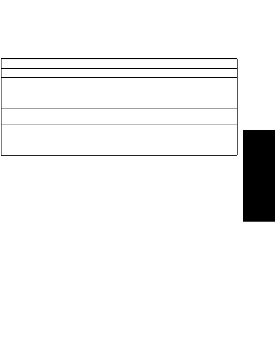
Version 2.0 UIDDataLog.Dat File Format
Data File Formats for
UIDChecker Software
F
v2.3.1, Dec 2008 Getting Started With Your UID Compliance Verifier F-9
– “Exposure:” and the exposure value
– “Gain:” and the gain value
– “Aperture:” and the current aperture value (e.g., AUTO or 4 or 5 or 6 or
7 or 8 or 9 or 10 or 11 or 12 or 13 or 14 or 15 or 16 or 17 or 18 or 19 or
20)
– “Call Target Contrast:” and the Contrast% (e.g., ##%)
– “Calibrated since Startup:” and the state (e.g., True or False)
– “Pixels/(0.1)inch:” and the value
– “Min/Max Raw Contrast Values:” and the values (e.g., ## / ##)
– User defined Field 1
– User defined Field 2
– User defined Field 3
– User defined Field 4
– User defined Field 5
TABLE F–5. AS9132 Laser Option
“AS9132 Laser”
“Module Fill:” followed by the X and Y values (e.g., “X / Y = ##% / ##%”)
“Contrast:” followed by Pass or Fail (e.g., “P” or “F”) and the contrast value (e.g., “Value = ##
“%”) and the qualifier (e.g., “UN_Cal” or “SELF_Cal” or “REFL_Cal” or “???”)
“Angle of Distortion:” followed by Pass or Fail (e.g., “P” or “F”) and the value
(e.g., “Value = ##”) degrees
“Matrix Size:” followed by Pass or Fail (e.g., “P” or “F”) and followed by COMMA (e.g., “,”)
followed by “< 1.000 INCHES” or “> 1.000 INCHES”
“Size: Height / Width =” followed by the current height and width and the units
(e.g., “## / ## PIXELS” or “INCHES” or “???”)
“ECC Level:” followed by the current ECC level (e.g., “ECC200” or “ECC140” or “ECC100” or
“ECC080” or “ECC050” or “ECC000” or “ECC250” or “???”)
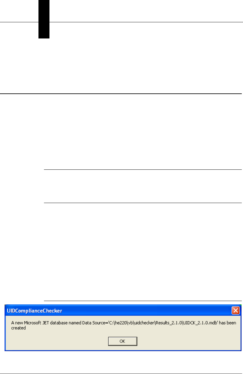
Appendix FData File Formats for UIDChecker Software
F-10 Getting Started With Your UID Compliance Verifier v2.3.1, Dec 2008
– Customer Graphics (e.g., “Logo:” and the Path to the Customer Logo
file)
Version 2.1 UIDDataLog.csv File Format
The following information is a detailed listing of the comma-delimited contents
for a version 2.1 data file. Using this description, you should be able to transfer
the data into your local Excel program or a database.
Due to the complexity of parsing rules for the results as presented in the comma-
delimited results file, results are now provided in the same alphabetical order as
in the MDB database record and each field is prefixed with a tag name in the
form “<tag name>”, to make parsing easier. All fields are always written, even if
empty.
Note: The “Store Results in MDB database” option must be selected to generate a
comma-delimited file output as the fields in the comma-delimited file are taken
from the database record. This also has the advantage of providing the value
without needing to parse it from a text string.
<20xClearSpace>,FALSE,<Angle>,68,<AngleOfDistortionGrade>,,<AngleOfDistortionValue>,,<A
perture>,5,…
Recording to an MDB database may be enabled through the Results Setup dialog
by selecting the Store Results in MDB database and CSV file option. This setting
is saved in the registry for the user so that it is remembered the next time
UIDChecker™ is started.
The first time a reading is taken after enabling the database, the dialogs displayed
in Figure F–1 and Figure F–2 are displayed to provide positive feedback that the
database was created and the table within the database was created.
FIGURE F–1. MDB Database Startup Sequence
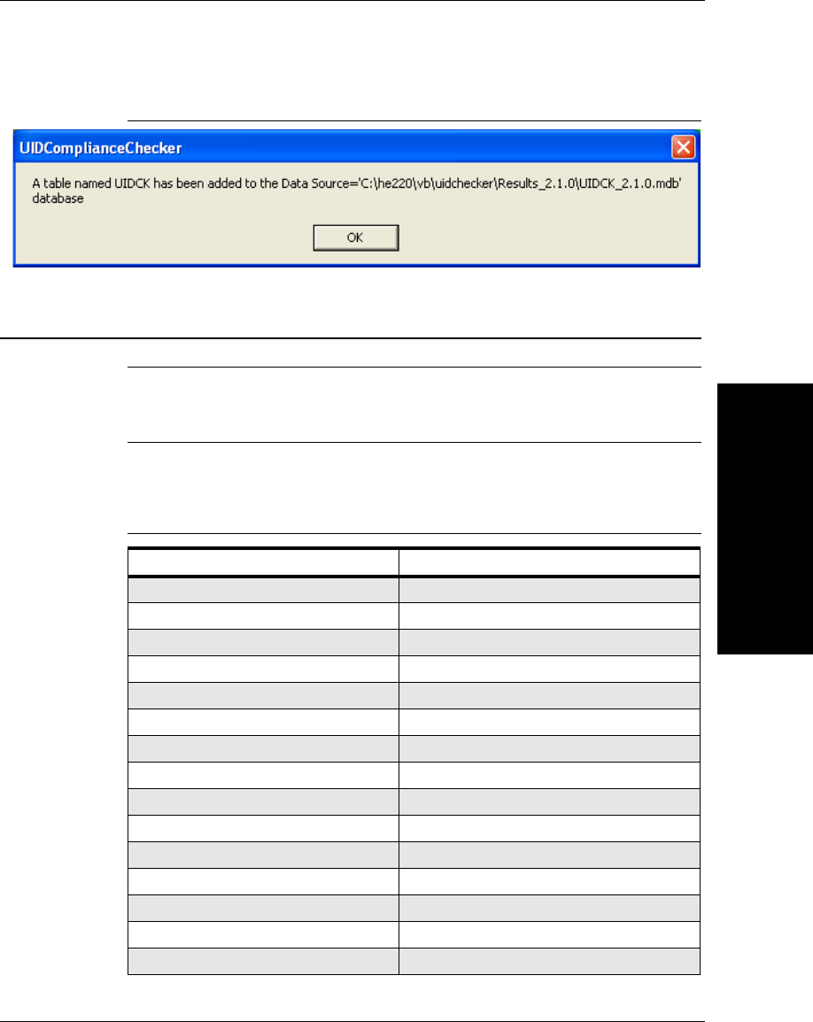
Version 2.1 DataBase Table Layout
Data File Formats for
UIDChecker Software
F
v2.3.1, Dec 2008 Getting Started With Your UID Compliance Verifier F-11
FIGURE F–2. MDB Database Startup Sequence Continued
Version 2.1 DataBase Table Layout
Note: This database is fully described in “Store Results in MDB Database and
CSV File” starting on page 3-23. Please refer to this section for implementation
details.
The database table layout is as follows:
TABLE F–6. Database Table Layout
Variable Size,
20xClearSpace VarChar(32),
Angle int,
AngleOfDistortionGrade VarChar(4),
AngleOfDistortionValue int,
Aperture VarChar(8),
AxialNonUniformityGrade VarChar(4),
AxialNonUniformityValue Double,
Calibrated VarChar(64),
CalibratedSinceStartup VarChar(64),
CalTargetContrast int,
CellSizeError VarChar(16),
CellSizeGrade VarChar(4),
CellSizeValue Double,
CellUnitReportString VarChar(8),
Construct VarChar(32),
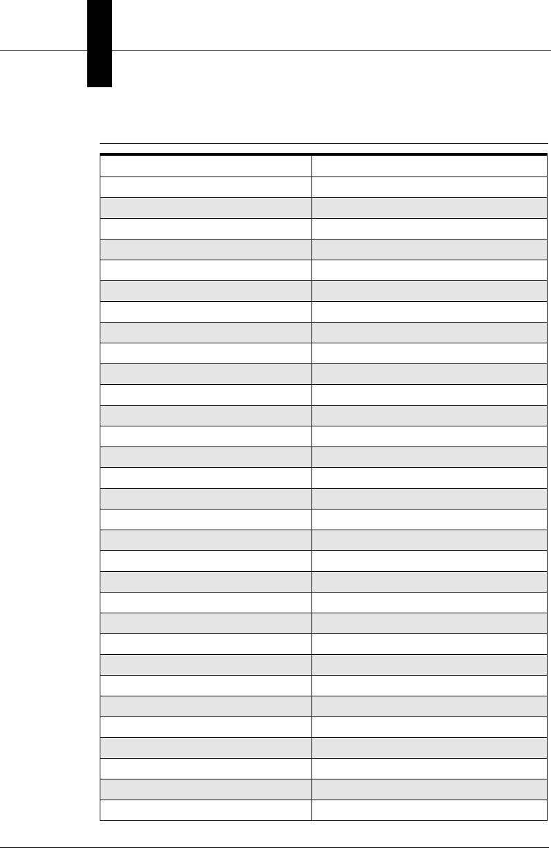
Appendix FData File Formats for UIDChecker Software
F-12 Getting Started With Your UID Compliance Verifier v2.3.1, Dec 2008
ContrastGrade VarChar(4),
ContrastReportString VarChar(32),
ContrastValue int,
CustomerFields1 VarChar(132),
CustomerFields2 VarChar(132),
CustomerFields3 VarChar(132),
CustomerFields4 VarChar(132),
CustomerFields5 VarChar(132),
DataElement1 VarChar(64),
DataElement2 VarChar(64),
DataElement3 VarChar(64),
DataElement4 VarChar(64),
DataElement5 VarChar(64),
DataElement6 VarChar(64),
DataQualifier VarChar(64),
DotCenterOffsetGrade VarChar(4),
DotCenterOffsetValue int,
DotSizeOffsetGrade VarChar(4),
DotSizeOffsetValue int,
ECCLevel VarChar(8),
Exposure int,
FixedPatternDamageGrade VarChar(4),
Gain int,
GridNonUniformityGrade VarChar(4),
GridNonUniformityValue Double,
HTMLFileName VarChar(255),
ImgFileName VarChar(255),
LastUIDString VarChar(128),
Logo VarChar(255),
MatrixHeightValue Double,
MatrixSizeError VarChar(16),
TABLE F–6. Database Table Layout (continued)
Variable Size,
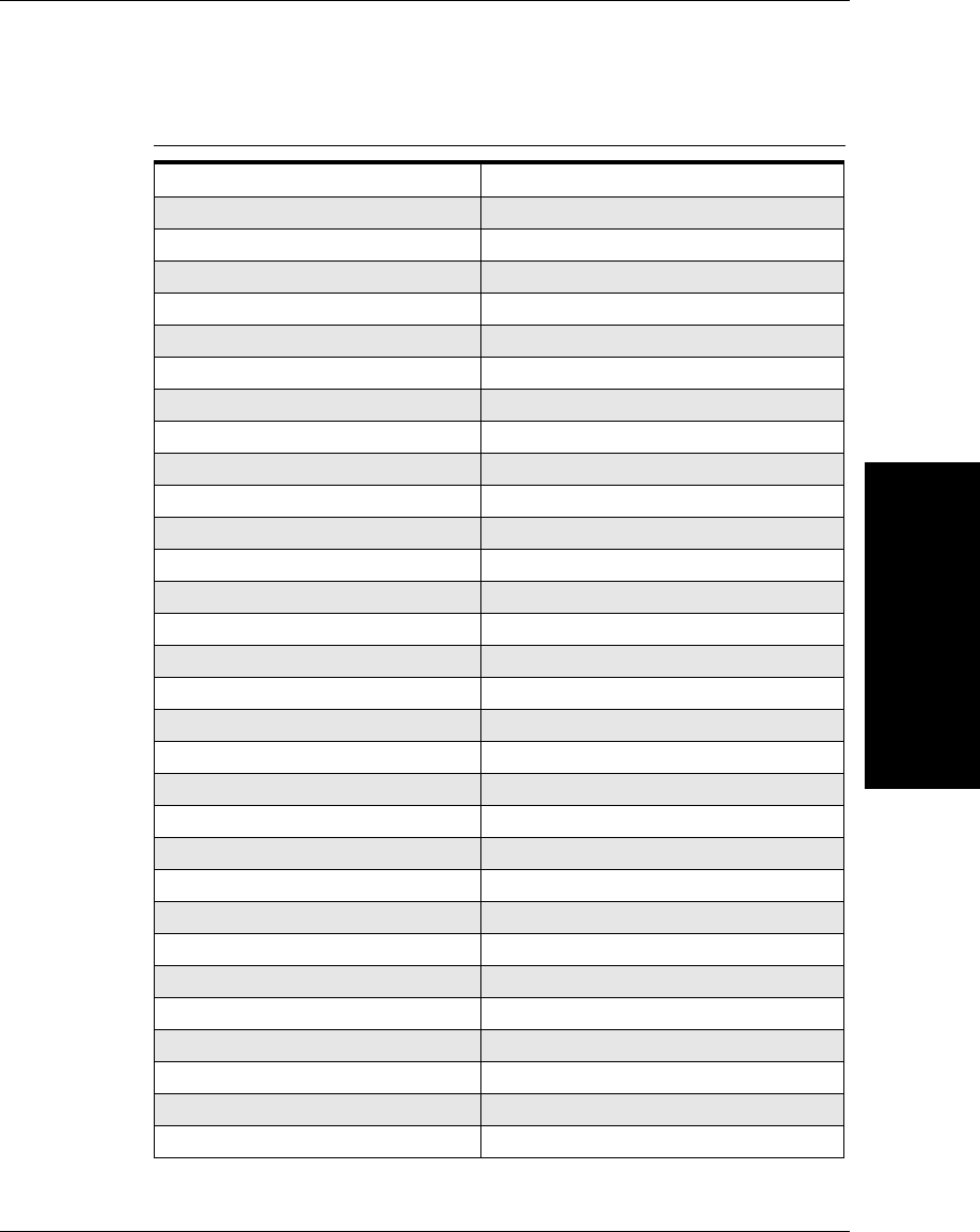
Version 2.1 DataBase Table Layout
Data File Formats for
UIDChecker Software
F
v2.3.1, Dec 2008 Getting Started With Your UID Compliance Verifier F-13
MatrixSizeGrade VarChar(4),
MatrixWidthValue Double,
MaxRawContrastValue int,
MinRawContrastValue int,
ModulationGrade VarChar(4),
ModuleFillGrade VarChar(4),
ModuleFillXValue int,
ModuleFillYValue int,
NominalModuleSizeGrade VarChar(4),
NominalModuleSizeValue Double,
OverrideCellSize VarChar(8),
OvalityGrade VarChar(4),
OvalityValue int,
OverallGrade VarChar(4),
PixelsPerInch int,
PrintGrowthGrade VarChar(4),
PrintGrowthXValue int,
PrintGrowthYValue int,
RawData VarChar(255),
ReaderName VarChar(32),
ReferenceDecodeGrade VarChar(4),
SequenceNumber VarChar(12),
SoftwareRev VarChar(8),
TimeofLastResult date,
UnusedErrorCorrectionGrade VarChar(4),
UnusedErrorCorrectionValue Double,
ValidAndVerifPass VarChar(8),
ValidateFailure VarChar(128),
ValidISO15434Pass VarChar(8),
ValidUIDPass VarChar(8),
TABLE F–6. Database Table Layout (continued)
Variable Size,
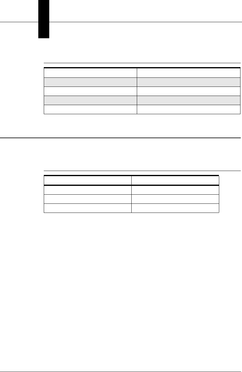
Appendix FData File Formats for UIDChecker Software
F-14 Getting Started With Your UID Compliance Verifier v2.3.1, Dec 2008
Version 2.2 DataBase Table Layout
The Version 2.2 database table layout is identical to the Version 2.3 database
table layout except for the following:
VerificationPass VarChar(8),
VerificationType VarChar(32),
VerifyFailure VarChar(128),
VerifyReadPass VarChar(8),
TABLE F–7. Database Table Layout Differences Between V2.3 & V2.2
V2.3 V2.2
AssociatedCpnLbnString AssociatedPartNumberString
EditUIIforCpnLbn EditUIIforPartNumber
EnableCpnLbnSupport EnablePNRSupport
TABLE F–6. Database Table Layout (continued)
Variable Size,

v2.3.1, Dec 2008 Getting Started With Your UID Compliance Verifier G-1
G
Certification &
Specifications
G
APPENDIX G Certification & Specifications
CE Compliance
The UID-LDP and UID-DPM have been certified to conform to the requirements
of Council Directives 2004/108/EC, 73/23/EEC, and 93/68/EEC to comply with
the following European Standards:
• EN61326:1997 A3:2003 Class A
• EN61010-1:2001-02
• EN60825-1:1993 A2 2001-01
• EM61000-6-2:2001
• EM61000-6-4:2001
This is a Class A product; in a domestic environment, this product may cause
radio interference, in which case, the user may be required to make adequate
measures.
All Microscan products bearing the CE mark have been declared to be in
conformance with the applicable EEC Council Directives. However, certain
factory installed options or customer requested modifications may compromise
electromagnetic compatibility and prohibit use of the CE mark. Note that the use
of interconnect cables that are not properly grounded and shielded may affect CE
compliance.
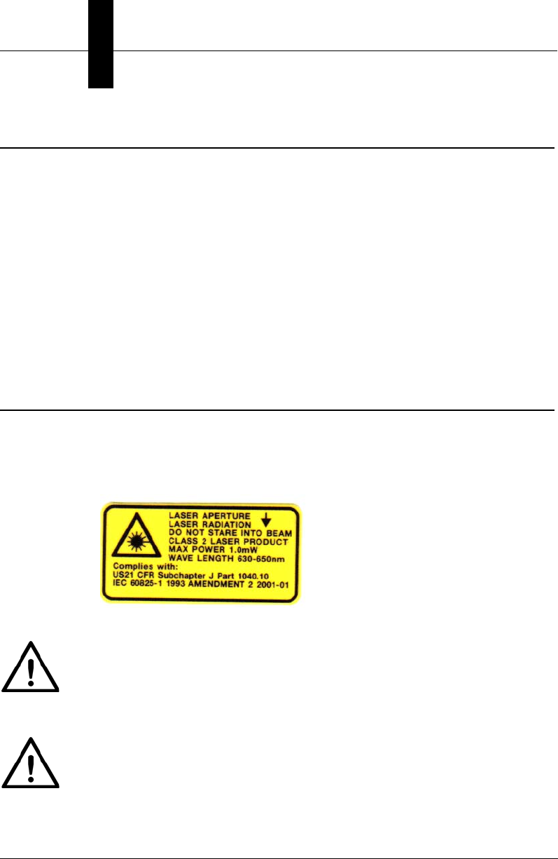
Appendix GCertification & Specifications
G-2 Getting Started With Your UID Compliance Verifier v2.3.1, Dec 2008
FCC Statement
This equipment has been tested and found to comply with the limits for a Class A
digital device, pursuant to Part 15 of the FCC Rules. These limits are designed to
provide reasonable protection against harmful interference when the equipment
is operated in a commercial environment. This equipment generates, uses, and
can radiate radio frequency energy and, if not installed and used in accordance
with the instruction manual, may cause harmful interference to radio
communications. Operation of this equipment in a residential area is likely to
cause harmful interference, in which case, you will be required to correct the
interference at your own expense.
Changes or modifications not expressly approved by the party responsible for
compliance could void your authority to operate the equipment.
FDA Statement
This equipment complies with:
US21 CFR Subchapter J Part 1040.10
IEC 60825-1:1993 Amendment 2 2001-01
Caution
The UID-LDP can be set to use targeting lasers. If the targeting lasers are
activated, do not stare into the beams. The UID-LDP’s targeting lasers have been
rated as Class II lasers by IEC 60825-1.
Warning
DO NOT LOOK DIRECTLY AT THE BEAMS OF THE LASER!

Specifications
Certification &
Specifications
G
v2.3.1, Dec 2008 Getting Started With Your UID Compliance Verifier G-3
Specifications
UID-LDP
Physical Characteristics
Dimensions: 13” L x 10” W x 11.6” H
(33.0 cm L x 25.4 cm W x 29.4 cm H)
Power Requirements: AC Adapter 100-250 VAC, 0.5A
50/60 Hz input, 24V at 500 mA output
Illumination: Embedded Class 1 LED
Red LED: 640 nm
Targeting Lasers: Class II
Weight: 17.2 lb (7.5 kg)
Performance Characteristics
Interfaces: Ethernet for normal operation,
RS-232 baud rates 115.2 Kbps for debugging
Field of View: 1.0” x 0.75” (25.4 mm x 19 mm)
Depth of Field: 0.125” (3.175 mm)
Minimum Element Size: 0.0075” (0.19 mm)
Optical Resolution: 660 x 494 Pixels
Light Configurations: 90
Programming: Windows 2000 / XP / Vista Business
Decode Capability: Data Matrix, ECC200
User Environment
Operating Temperature: 32° F to 104° F (0° C to 40° C)
Storage Temperature: 122° F (50° C) Max

Appendix GCertification & Specifications
G-4 Getting Started With Your UID Compliance Verifier v2.3.1, Dec 2008
UID-DPM
Physical Characteristics
Dimensions: 6.7” L x 6.1” W x 8.3” H
(17.0 cm L x 15.5 cm W x 21.1 cm H)
Power Requirements: AC Adapter 100-240 VAC, 1.6A
50/60 Hz input, 24V at 1.5A output
Illumination: Embedded Class 1 LED
Red LED: 640 nm
Weight: 5.95 lb (2.7 kg)
Performance Characteristics
Interfaces: Ethernet for normal operation,
RS-232 baud rates 115.2 Kbps for debugging
Field of View: 1.19” x 0.86” (30.2 mm x 21.8 mm)
Depth of Field: Up to 0.125” (3.175 mm)
Minimum Element Size: 0.0075” (0.19 mm)
Optical Resolution: 660 x 494 Pixels
Light Configurations: 90, D, 45Q, 30Q,
30T (North/South, East/West),
30S (North, East, South, West)
Programming: Windows 2000 / XP / Vista Business
Decode Capability: Data Matrix, ECC200
User Environment
Operating Temperature: 32° F to 104° F (0° C to 40° C)
Storage Temperature: 122° F (50° C) Max

v2.3.1, Dec 2008 Getting Started With Your UID Compliance Verifier Index-1
Index
A
ADO Components
error messages 3-25
fixing error E-1
Allow Multiple Selection 3-34
Analyzing Results 4-1
UID compliance check 4-1
Apply Manual Photometry Values Button 3-17
Archive
tab 3-34
to 3-35
Assembling Lights D-3
Attaching
camera D-2
lights to camera D-4
Automatically Save the Result with Each
Read 3-23
B
Back to Summary Button 3-30
Buttons
apply manual photometry values 3-17
back to summary 3-30
cancel read and rotate B-4
clear
log 3-6
log view 3-27
configure camera through serial port 3-11
connect via serial 3-12
copy 3-36
default 3-17
delete
result 3-32
result(s) 3-34
learn photometry 3-17
live video 2-7, 2-9, 3-7, B-1, B-4
move 3-36
next result 3-32
normalize D-11
previous result 3-32
print result 3-9, 3-32, 3-34
read 3-8
and rotate 3-8, 3-21, B-1, B-2
uid mark 3-8
save result 3-9
show summary results 3-32
start search 3-34
turn laser
off 3-13
on 3-13
view result 3-9
C
Calibrate 3-13, 3-15
Calibration
reflectance 2-3, D-12
testing 2-5
Camera
attaching to uid-dpm stand D-2
Cancel Read And Rotate Button B-4
Cell Size Restrictions
variance to override 3-25
Certification G-1
Change Results Path 3-27
Clear
log button 3-6
log view button 3-27

Index
Index-2 Getting Started With Your UID Compliance Verifier v2.3.1, Dec 2008
Company Logo
specifying your 3-21
Components 1-6
Configurations for the multifunction light 1-16
Configure Camera Through Serial Port
Button 3-11
Configuring the Verifier D-9
Connect via Serial Button 3-12
Containing Text 3-34
Control the Lighting 1-17
Copy Button 3-36
Customer Fields
defining 3-21
D
Data File Formats
uidchecker software F-1
Data Matrix
cell size 4-11
quality verification standard 4-11
Database
mdb 3-23
table layout 3-24
Default Button 3-17
Define Customer Fields 3-21
Delete
result button 3-32
result(s) button 3-34
DHCP Explained 1-12
Diffuse
off-axis lighting 1-16
perpendicular lighting 1-16
E
ECC 200 4-11
Error Messages
ADO components 3-25
validation 3-37
verification 3-39
Exit 3-10
Exposure 3-16
F
F8hotkey to read a mark 3-8
File
menu 3-10
naming scheme 3-1
Files
redirect output 3-27
Find Reader Menu Item 3-10
First Time Startup 2-1
FOV
uid-dpm 1-3
uid-ldp 1-2
H
HawkEye Sensor Lighting Normalization D-10
I
Images
store with results 3-23
Indicators
light 3-4
Installing Long Feet Spacers 1-7
L
Layout of the Database Table 3-24
Learn Photometry Button 3-17
Lenses
preparing D-3
Lighting 1-15, 3-16
configurations 1-16
control 1-17
diffuse
off-axis 1-16
perpendicular 1-16
indicators 3-4
low angle
four direction 1-16
one direction 1-17
two direction 1-16
medium angle four direction 1-17
Lights
assembling D-3
attaching to camera D-4
Live 3-7
Live Video Button 1-17, 2-6, 2-7, 2-9, 3-7, B-1,
B-4
Loading Software 1-9
Long Feet Spacers
installing 1-7
Look In 3-34

Index
v2.3.1, Dec 2008 Getting Started With Your UID Compliance Verifier Index-3
Low Angle
four direction lighting 1-16
one direction lighting 1-17
two direction lighting 1-16
M
Mark Quality
understanding 4-11
MDB
database 3-23
Measurements
rotational consistency of B-1
Medium Angle Four Direction Lighting 1-17
Menus
file 3-10
reader 3-10
Mode
secured 3-2
Move Button 3-36
N
Network
setting up D-9
Networking to the Reader 1-10
New Folder Name 3-36
Next Result Button 3-32
Normalization
sensor lighting D-10
NORMALIZE Button D-11
O
Operating Temperature 1-7
Operation
testing 2-8
Output Files
redirect 3-27
Overview
uidchecker
buttons 3-7
user interface 3-2
P
PC
requirements 1-7
Portable Operation
uid-dpm 1-5
Positioning Data Matrix for Verification 1-17
Powering Up 1-9
Previous Result Button 3-32
Print Result Button 3-9, 3-32, 3-34
R
Read
and rotate button 3-8, 3-21, B-1, B-2
when it appears 3-21
button 3-8
menu
turn laser off 3-13
uid mark button 3-8
Reader Menu 3-10
calibrate 3-13
find reader 3-10
Redirect Output Files 3-27
Reflectance Calibration 2-3, D-12
Requirements
pc 1-7
Result List Box 3-34
Results
analyzing 4-1
automatically save with each read 3-23
data file 4-6
path
changing 3-27
setup 3-22
stored in mbd database 3-23
view 3-28
Rotational Consistency of Measurements B-1
S
Save
result button 3-9
uid read result 3-23
Scheme
file naming 3-1
Search Tab 3-32
Secured Mode 3-2
Setting Up
network D-9
uid-dpm stand C-1
Setup
results 3-22
Show
summary results button 3-32

Index
Index-4 Getting Started With Your UID Compliance Verifier v2.3.1, Dec 2008
uid details above image 3-23
verification details in on-screen results
view 3-23
Software
loading 1-9
upgrading D-9
Specifications G-1
Standards 3-36
Start Search Button 3-34
Startup 2-3
first time 2-1
Static IP Explained 1-12
Storage Temperature 1-7
Store
images with results 3-23
results in mbd database 3-23
Summary Report B-6
T
Tabs
archive 3-34
search 3-32
view 3-30
Testing
calibration 2-5
operation 2-8
the uid compliance verifier 2-3
Triggers 1-18
Turn Laser
off button 3-13
on button 3-13
U
UID
compliance check
analyzing results 4-1
compliance verifier
testing 2-3
details
show above image 3-23
graphical display details 3-3
read details 3-3
results data file 4-6
UIDChecker
buttons
overview 3-7
data file formats F-1
upgrading A-1
user interface
overview 3-2
UID-DPM
field of view 1-3
portable operation 1-5
setting up stand C-1
UID-LDP Field of View 1-2
Understanding Mark Quality 4-11
Upgrading
from a previous version 1-13
software D-9
uidchecker A-1
V
Variance to Override Cell Size Restrictions
3-25
Verification
details
show in on-screen results view 3-23
positioning data matrix 1-17
type 3-18
Verifier
configuring D-9
Verifier Setting
recommended
25mm lens D-5
35mm lens D-7
View
result button 3-9
results 3-28
tab 3-30
W
Windows
2000 1-7
Vista Business 1-7
xp 1-7
