Vision HAWK Smart Camera Guide Visionhawkguide
2013-01-15
: Microscan Visionhawkguide visionhawkguide Q12013 LaunchCentral PartnerSite
Open the PDF directly: View PDF ![]() .
.
Page Count: 177 [warning: Documents this large are best viewed by clicking the View PDF Link!]
- Vision HAWK Smart Camera Guide
- Contents
- PREFACE Welcome!
- CHAPTER 1 Introduction
- CHAPTER 2 System Components
- CHAPTER 3 Optics and Lighting
- CHAPTER 4 Using EtherNet/IP
- APPENDIX A Connector Pinouts
- APPENDIX B Cable Specifications
- APPENDIX C General Specifications
- APPENDIX D Web HMI
- APPENDIX E Allen-Bradley PLC Setup via EDS
- APPENDIX F Allen-Bradley PLC Setup via Generic Ethernet Module
- APPENDIX G Demo PLC Code
- APPENDIX H Serial Commands
- APPENDIX I Vision HAWK Boot Modes
Vision HAWK Smart Camera Guide
84-016800-02 Rev A
Copyright ©2013
Microscan Systems, Inc.
Tel: +1.425.226.5700 / 800.762.1149
Fax: +1.425.226.8250
ISO 9001 Certified
Issued by TüV USA
All rights reserved. The information contained herein is proprietary and is provided solely for the purpose of
allowing customers to operate and/or service Microscan manufactured equipment and is not to be released,
reproduced, or used for any other purpose without written permission of Microscan.
Throughout this manual, trademarked names might be used. We state herein that we are using the names to the
benefit of the trademark owner, with no intention of infringement.
Disclaimer
The information and specifications described in this manual are subject to change without notice.
Latest Manual Version
For the latest version of this manual, see the Download Center on our web site at:
www.microscan.com.
Technical Support
For technical support, e-mail: helpdesk@microscan.com.
Warranty and Terms of Sale
For Standard Warranty information, see: www.microscan.com/warranty.
Microscan Systems, Inc.
United States Corporate Headquarters
+1.425.226.5700 / 800.762.1149
United States Northeast Technology Center
+1.603.598.8400 / 800.468.9503
European Headquarters
+31.172.423360
Asia Pacific Headquarters
+65.6846.1214
Statement of RoHS Compliance
All Microscan readers with a ‘G’ suffix in the FIS number are RoHS-Compliant. All compliant readers
were converted prior to March 1, 2007. All standard accessories in the Microscan Product Pricing Catalog
are RoHS-Compliant except 20-500013-01 and 98-000039-02. These products meet all the requirements
of “Directive 2002/95/EC” European Parliament and the Council of the European Union for RoHS compliance.
In accordance with the latest requirements, our RoHS-Compliant products and packaging do not contain
intentionally added Deca-BDE, Perfluorooctanes (PFOS), or Perfluorooctanic Acid (PFOA) compounds
above the maximum trace levels. To view the document stating these requirements, please visit:
http://eur-lex.europa.eu/LexUriServ/LexUriServ.do?uri=CELEX:32002L0095:EN:HTML
and
http://eur-lex.europa.eu/LexUriServ/LexUriServ.do?uri=OJ:L:2006:372:0032:0034:EN:PDF
Please contact your sales manager for a complete list of Microscan’s RoHS-Compliant products.
This declaration is based upon information obtained from sources which Microscan believes to be reliable, and from
random sample testing; however, the information is provided without any representation of warranty, expressed or
implied, regarding accuracy or correctness. Microscan does not specifically run any analysis on our raw materials or end
product to measure for these substances.
The information provided in this certification notice is correct to the best of Microscan’s knowledge at the date of publication.
This notice is not to be considered a warranty or quality specification. Users are responsible for determining the applicability
of any RoHS legislation or regulations based on their individual use of the product.
Regarding “RoHS Directive 2011_65_EU” Microscan produces Monitoring and Control Instruments as well as Industrial
Monitoring and Control Instruments as defined within the directive. Microscan has developed and is implementing a
RoHS2 compliance plan with the intention of bringing all active products listed in our current marketing literature within
full compliance as per the directive deadlines.
Key milestones for the transition plan are as follows:
• Complete internal product audit and supplier transition by July 2013.
• Initial “Monitoring and Control Instruments” RoHS2-compliant products available by July 2014.
• Initial “Industrial Monitoring and Control Instruments” RoHS2-compliant products available by July 2015.
• All new products introduced in 2014 are expected to be WEEE and RoHS2 compliant.
Microscan will mark the products with the ‘CE’ marking that complies with the RoHS2 process to acquire ‘CE’ certification
per the example given: Example 1 >> Machinery directive + EMC directive + RoHS2 = Declaration of Conformity.

Vision HAWK Smart Camera Guide Lv
Contents
PREFACE Welcome! viii
Purpose of This Manual viii
Manual Conventions viii
CHAPTER 1 Introduction 1-1
Product Summary 1-2
Features and Benefits 1-2
Applications 1-3
Package Contents 1-3
Vision HAWK Smart Camera Models 1-4
Part Number Structure 1-5
CHAPTER 2 System Components 2-1
Hardware Components 2-1
Important Label Information 2-8
Mounting and Wiring the Vision HAWK Smart Camera 2-9
Input/Output Wiring 2-16
Ground and Shield Considerations 2-17
Power Requirements 2-19
Status Indicators 2-20
AutoVISION Button 2-21
Setting Up a Job in AutoVISION 2-22
Trigger Debounce 2-27

Contents
vVision HAWK Smart Camera Guide
CHAPTER 3 Optics and Lighting 3-1
Optics 3-2
Lens Substitution 3-3
Illumination 3-5
CHAPTER 4 Using EtherNet/IP 4-1
Vision HAWK EtherNet/IP 4-2
Assembly Layout 4-4
Connection Properties: Class 3 Explicit Messaging: 4-14
EIP Control/Status Signal Operation 4-17
Data Type Descriptions and Equivalents in PLC and EDS/CIP Environments 4-18
PLC Tags and Serial Command Names 4-19
APPENDIX A Connector Pinouts A-1
Vision HAWK Smart Camera Connectors A-2
APPENDIX B Cable Specifications B-1
61-000160-01 Cable, Host, Ethernet, M12 8-pin Plug to RJ45, 1 m B-2
61-000162-01 Cable, Common, M12 12-pin Plug to M12 12-pin Socket, 1 m B-3
97-000003-01 Power Supply, M12 12-pin Socket, 1.3 m B-4
99-000020-02 Trigger, M12 4-pin Plug, NPN, Dark On, 2 m B-5
APPENDIX C General Specifications C-1
Dimensions C-8
Field of View and Working Distance C-10
APPENDIX D Web HMI D-1
Adding Options to the Base URL D-4
Basic Options D-4
Layout Options D-5
Settings Pages D-7
Style D-14
Additional Notes D-15
APPENDIX E Allen-Bradley PLC Setup via EDS E-1
AB Rockwell RSLogix 5000 v20 PLC Integration with EDS E-2
APPENDIX F Allen-Bradley PLC setup via Generic Ethernet Module F-1
Prepare the PLC: Integrate the Camera into a PLC Environment F-2

Contents
Vision HAWK Smart Camera Guide vi
APPENDIX G Demo PLC Code G-1
Glossary of Terms G-2
Demo Setup G-3
Description of PLC Tags G-5
Run the Camera: Runtime Operation of EtherNet/IP Demo G-15
APPENDIX H Serial Commands H-1
APPENDIX I Vision HAWK Boot Modes I-1

Vision HAWK Smart Camera Guide vii
Preface
PREFACE Welcome!
Purpose of This Manual
This manual contains detailed information about the Vision HAWK Smart
Camera.
Manual Conventions
The following typographical conventions are used throughout this manual.
• Items emphasizing important information are bolded.
• Menu selections, menu items and entries in screen images are
indicated as: Run (triggered), Modify..., etc.

Preface
YLLL Vision HAWK Smart Camera Guide

Vision HAWK Smart Camera Guide 1-1
1
Introduction
1
CHAPTER 1 Introduction
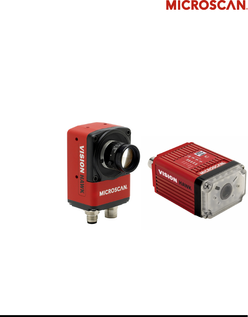
FIGURE 1–1. Vision HAWK Smart Camera, C-Mount and Standard Models

Chapter 1Introduction
1-2 Vision HAWK Smart Camera Guide
Product Summary
The Vision HAWK Smart Camera is a compact industrial smart camera
that provides powerful machine vision capabilities with a small form factor
and intuitive software interface. The Vision HAWK is designed for
industrial environments where IP65/67 enclosure and rugged M12
connectivity are required.
Fully-integrated I/O and communications make the Vision HAWK easy to
incorporate in virtually any machine vision application. Patented liquid
lens autofocus and modular optical zoom enables the Vision HAWK to
inspect objects at distances from 33 mm to 2 m and beyond.
Pressing the AutoVISION button at the back of the Vision HAWK enables
real time dynamic autofocus. When an object is centered in the field of
view and the AutoVISION button is pressed, the camera automatically
adjusts focal distance and sets internal parameters to optimize image
captures.
AutoVISION software, designed for use with the Vision HAWK, provides
an intuitive interface, step-by-step configuration, and a library of presets
that allow easy setup and deployment. For more complex vision
applications, the system can be upgraded from AutoVISION to
Visionscape.
Features and Benefits
• Standard and C-Mount models available
• SXGA (1280 x 960), WVGA (752 x 480), and WUXGA (2048 x 1088,
C-Mount model only) resolutions available
• World’s first vision system with liquid lens autofocus (standard models)
• Integrated lighting (standard models)
• Integrated Ethernet
• Flexible programming options for custom applications
• AutoVISION button for automatic targeting, calibration, and triggering
• Simplified configuration with AutoVISION software
• Fully scalable with Visionscape
• Applications can be ported to Visionscape PC-based machine vision

Applications
Introduction
1
Vision HAWK Smart Camera Guide 1-3
Applications
• Automotive assembly verification
• Part identification
• Label positioning
• Contents verification
• Electronics assembly verification and identification
• Semiconductor packaging and component inspection
• Auto ID (Data Matrix and other 2D symbologies, 1D, OCR)
Package Contents
Before you install AutoVISION software and connect your Vision HAWK
Smart Camera, please take a moment to confirm that the following items
are available:
• Vision HAWK Smart Camera — Your package contains one of the
available models listed in Table 1–1
• Microscan Tools Drive — USB flash drive containing AutoVISION software
• Required accessories such as a power supply or power cable

Chapter 1Introduction
1-4 Vision HAWK Smart Camera Guide
Vision HAWK Smart Camera Models
Table 1–1 lists and describes the Vision HAWK Smart Camera models.
TABLE 1–1. Vision HAWK Smart Camera Models
Part Number Vision HAWK Smart Camera Model
GMV-6800-1000G Vision HAWK, 1.3MP SXGA, AutoVISION, C-Mount
GMV-6800-1002G Vision HAWK, 1.3MP SXGA, AutoVISION+Visionscape, C-Mount
GMV-6800-1004G Vision HAWK, 1.3MP SXGA, AutoVISION+Verification/OCV, C-Mount
GMV-6800-1006G Vision HAWK, 1.3MP SXGA, AutoVISION+Visionscape+Verification/OCV, C-Mount
GMV-6800-1010G Vision HAWK, 0.4MP WVGA, AutoVISION, C-Mount
GMV-6800-1012G Vision HAWK, 0.4MP WVGA, AutoVISION+Visionscape, C-Mount
GMV-6800-1014G Vision HAWK, 0.4MP WVGA, AutoVISION+Verification/OCV, C-Mount
GMV-6800-1016G Vision HAWK, 0.4MP WVGA, AutoVISION+Visionscape+Verification/OCV, C-Mount
GMV-6800-1030G Vision HAWK, WUXGA, Mono, AutoVISION, C-Mount
GMV-6800-1032G Vision HAWK, WUXGA, Mono, AutoVISION+Visionscape, C-Mount
GMV-6800-1034G Vision HAWK, WUXGA, Mono, AutoVISION+Verification/OCV, C-Mount
GMV-6800-1036G Vision HAWK, WUXGA, Mono, AutoVISION+Visionscape+Verification/OCV, C-Mount
GMV-6800-1100G Vision HAWK, SXGA, Built-In Lighting, AutoVISION, 15° Lens
GMV-6800-1102G
Vision HAWK, SXGA, Built-In Lighting, AutoVISION+Visionscape, 15° Lens
GMV-6800-1104G
Vision HAWK, SXGA, Built-In Lighting, AutoVISION+Verification/OCV, 15° Lens
GMV-6800-1106G
Vision HAWK, SXGA, Built-In Lighting, AutoVISION+Visionscape +Verification/OCV, 15° Lens
GMV-6800-1110G Vision HAWK, WVGA, Built-In Lighting, AutoVISION, 15° Lens
GMV-6800-1112G
Vision HAWK, WVGA, Built-In Lighting, AutoVISION+Visionscape, 15° Lens
GMV-6800-1114G
Vision HAWK, WVGA, Built-In Lighting, AutoVISION+Verification/OCV, 15° Lens
GMV-6800-1116G
Vision HAWK, WVGA, Built-In Lighting, AutoVISION+Visionscape +Verification/OCV, 15° Lens
GMV-6800-1200G Vision HAWK, SXGA, Built-In Lighting, AutoVISION, 30° Lens
GMV-6800-1202G
Vision HAWK, SXGA, Built-In Lighting, AutoVISION+Visionscape, 30° Lens
GMV-6800-1204G
Vision HAWK, SXGA, Built-In Lighting, AutoVISION+Verification/OCV, 30° Lens
GMV-6800-1206G
Vision HAWK, SXGA, Built-In Lighting, AutoVISION+Visionscape +Verification/OCV, 30° Lens
GMV-6800-1210G Vision HAWK, WVGA, Built-In Lighting, AutoVISION, 30° Lens
GMV-6800-1212G
Vision HAWK, WVGA, Built-In Lighting, AutoVISION+Visionscape, 30° Lens
GMV-6800-1214G
Vision HAWK, WVGA, Built-In Lighting, AutoVISION+Verification/OCV, 30° Lens
GMV-6800-1216G
Vision HAWK, WVGA, Built-In Lighting, AutoVISION+Visionscape+Verification/OCV, 30° Lens
GMV-6800-1300G Vision HAWK, SXGA, Built-In Lighting, AutoVISION, 45° Lens
GMV-6800-1302G
Vision HAWK, SXGA, Built-In Lighting, AutoVISION+Visionscape, 45° Lens
GMV-6800-1304G
Vision HAWK, SXGA, Built-In Lighting, AutoVISION+ Visionscape +Verification/OCV, 45° Lens
GMV-6800-1306G
Vision HAWK, SXGA, Built-In Lighting, AutoVISION+Visionscape+Verification/OCV, 45° Lens
Part Number Structure
Introduction
1
Vision HAWK Smart Camera Guide 1-5
Part Number Structure
GMV-6800-1310G Vision HAWK, WVGA, Built-In Lighting, AutoVISION, 45° Lens
GMV-6800-1312G
Vision HAWK, WVGA, Built-In Lighting, AutoVISION+Visionscape, 45° Lens
GMV-6800-1314G
Vision HAWK, WVGA, Built-In Lighting, AutoVISION+Verification/OCV, 45° Lens
GMV-6800-1316G
Vision HAWK, WVGA, Built-In Lighting, AutoVISION+Visionscape+Verification/OCV, 45° Lens
GMV 6800
General
Machine
Vision
Vision
HAWK
Comm Lens Sensor Options RoHS
1 = Ethernet
0 = C-Mount 0 = CCD
(SXGA) 0 = AutoVISION
G = RoHS
compliant
1 = 15° Optics 1 = CMOS
(WVGA)
2 = AutoVISION +
Visionscape
2 = 30° Optics
3 = CMOS
(WUXGA)
4 = AutoVISION +
Verification/OCV
3 = 45° Optics
6 = AutoVISION +
Visionscape +
Verification/OCV
TABLE 1–1. Vision HAWK Smart Camera Models
Part Number Vision HAWK Smart Camera Model

Chapter 1Introduction
1-6 Vision HAWK Smart Camera Guide

Vision HAWK Smart Camera Guide 2-1
2
System Components
2
CHAPTER 2 System Components
This section contains information about system components as well as
information to help you connect the Vision HAWK Smart Camera. Specific
information describes connectors, adapters, cables, pinouts, and signals.
Note: There are no user-serviceable parts inside.
Hardware Components
Table 2-1 lists Vision HAWK Smart Camera hardware components.
TABLE 2–1. Vision HAWK Smart Camera Hardware Components
Part Number Description
Demo Kit
98-000215-01 Demo Kit (Power Supply, Camera Stand, Ethernet Host Cable, Carrying Case, Documentation)
Power Supplies
97-000003-01 Power Supply, M12 12-pin Socket, 1.3 m
97-000003-02 Power Supply, M12 12 pin Plug, 1.3m
Communication Devices and Cables
98-000103-01 QX-1 Interface Device
61-000148-01 Cordset, Common, M12 12 Pin, Socket (Ultralock) to M12 12 Pin, Plug (Ultralock), 3M
61-000148-02 Cordset, Common, M12 12 Pin, Socket (Screw-on) to M12 12 Pin Plug (Screw-on), 3M
61-000162-01 Cordset, Common, M12 12 Pin, Socket (Ultralock) to M12 12 Pin, Plug (Ultralock), 1M
61-000162-02 Cordset, Common, M12 12 Pin, Socket (Screw-on) to M12 12 Pin Plug (Screw-on), 1M
61-000153-01 Cordset, Host, Serial, M12 12 Pin Socket (Ultralock) to DB9 Socket, 1M

Chapter 2System Components
2-2 Vision HAWK Smart Camera Guide
61-000153-02 Cordset, Host, Serial M12 12 pin Socket (Screw-on) to DB9 Socket, 1M
61-000164-01 Cordset, Host, Serial, M12 12 pin Socket (Ultralock) to DB9 Socket, 3M
61-000164-02 Cordset, Host, Serial, M12 12 pin Socket (Screw-on) to DB9 Socket, 3M
61-000152-01 Cordset, Host, Serial M12 12 pin Plug (Ultralock) to DB9 Socket, 1M
61-000152-02 Cordset, Host, Serial, M12 12 pin Plug (Screw-down) to DB9 Socket, 1M
61-000165-01 Cordset, Host, Serial M12 12 pin Plug (Ultralock) to DB9 Socket, 3M
61-000165-02 Cordset, Host, Serial M12 12 pin Plug (Screw-on) to DB9 Socket, 3M
61-000163-01 Cordset, Host, Ethernet, M12 8 pin Plug (Ultralock) to RJ45, 3M
61-000163-02 Cordset, Host, Ethernet, M12 8 pin Plug(Screw-on) to RJ45, 3M
61-000160-01 Cordset, Host, Ethernet, M12 8 pin Plug (Ultralock) to RJ45, 1M
61-000160-02 Cordset, Host, Ethernet, M12 8 pin Plug (Screw-on) to RJ45, 1M
61-000161-01 Cordset, M12 12 pin Plug (Ultralock) to MS-5100, 3M
61-000161-02 Cordset, M12 12 pin Plug (Screw-on) to MS-5100, 3M
61-000172-01 Cordset, M12 12 pin Plug (Ultralock) to M12 12 pin Socket (Ultralock) to DB25 Plug
61-000158-03 Cordset, M12 12 Pin Plug & Socket (Ultralock) to MS-Connect 210, RS-232, 2M
61-000158-04 Cordset, M12 12 Pin Plug & Socket (Ultralock) to MS-Connect 210, RS-422/485, 2M
61-000166-01 Cordset, M12 12 Pin Plug (Ultralock) to Flying Leads, 3M
61-000166-02 Cordset, M12 12 Pin Plug (Screw-on) to Flying Leads, 3M
61-000167-01 Cordset, M12 12 Pin Socket (Ultralock) to Flying Leads, 3M
61-000167-02 Cordset, M12 12 Pin Socket (Screw-on) to Flying Leads, 3M
61-000207-01 Cordset, C-Mount-to-Smart Series Light
FIS-0210-0001G MS-Connect 210, Connectivity Box with Display
FIS-0210-0002G MS-Connect 210, Connectivity Box
FIS-0210-0003G MS-Connect 210, Connectivity Box with Display and Ethernet
FIS-0210-0004G MS-Connect 210, Connectivity Box with Ethernet
98-000013-04 Relay Module, 120VAC, 3 Amp Output, Series 70, Type SM, for MS-Connect 210
98-000013-05 Relay Module, 240VAC, 3 Amp Output, Series 70, Type SM for MS-Connect 210
98-000013-06 Relay Module, 24VDC, 3 Amp Output, Series 70, Type SM for MS-Connect 210
Accessories
98-000143-01 Adapter Plate Kit
98-000148-01 L-Bracket Kit
98-000144-01 Right Angle Mirror Kit
98-000146-01 Window Replacement Kit
98-000147-01 15° Lens Kit
98-000147-02 30° Lens Kit
98-000147-03 45° Lens Kit
98-000205-01 Glass WIndow Kit with Infrared (IR) Filter
98-000206-01 Glass Window Kit
98-500006-01 Mounting Plate Kit, Flat, Custom Surfaces
TABLE 2–1. Vision HAWK Smart Camera Hardware Components (Continued)
Part Number Description
Hardware Components
System Components
2
Vision HAWK Smart Camera Guide 2-3
20-610024-01 Trigger Connector, 4-pin Plug (screw terminal and field-wireable) (for self-wiring)
98-000037-01 Extension Kit, All Cameras, 6 inch
98-000054-01 Kit, Mounting Stand Base Plate, Small
98-000016-01 Mounting Arm/Adapter Kit, 6 inch
99-000056-01 Accessory, Bracket, DOAL 50 to Vision HAWK
99-000058-01 Accessory, Bracket, DOAL 75 to Vision HAWK
99-000060-01 Accessory, Bracket, DOAL 100 to Vision HAWK
99-000061-01 Accessory, Bracket, DOAL to C-MOUNT Vision HAWK
99-000050-01 Accessory, Bracket,R-100 to Vision HAWK
99-000052-01 Accessory, Bracket,R-60/70 to Vision HAWK
99-000049-01 Accessory, Bracket,R-100 to C-MOUNT Vision HAWK
99-000051-01 Accessory, Bracket,R-60/70 to C-MOUNT Vision HAWK
98-92800471 5MM Extension Tube for C-Mount Lenses
98-CO206 Lens Extension Tube Set 0.5, 1, 5, 10, 20, 40mm
98-92800571 Lens 8mm F/1.4-16, FT 25.5mm P 0.5mm, 2/3" C-MNT
98-92800572 Lens 12mm F/1.8-16, FT 25.5mm P 0.5mm, 2/3" C-MNT
98-92800573 Lens 16mm F/1.4-16, FT 25.5mm P 0.5mm, 2/3" C-MNT
98-92800574 Lens 25mm F/1.6-16, FT 25.5mm P 0.5mm, 2/3" C-MNT
98-92800575 Lens 35mm F/2.1-22, FT 25.5mm P 0.5mm, 2/3" C-MNT
98-92800576 Lens 50mm F/2.8-22, FT 25.5mm P 0.5mm, 2/3" C-MNT
98-92800577 Lens 75mm F/3.9-32, FT 25.5mm P 0.5mm, 2/3" C-MNT
98-92800311 Lens, Skylight UV Filter 25.5mm Thread
98-92800371 Polarizing Filter 25.5mm Thread
98-000218-01 Lens Protection Housing, Standard Length (up to 48mm)
98-000226-01 Lens Protection Housing, Long (up to 72mm)
Object Detectors
99-000020-01 Photo Sensor, M12 4pin Plug, NPN, Dark Off, 2m
99-000020-02 Photo Sensor, M12 4-pin Plug, NPN, Dark On, 2 m
Documentation
37-000010-01 Microscan Tools Drive (Software, User’s Manuals, Quick Start Guides, Configuration Guides, links to
other documents on Microscan website)
Note: Additional hardware components are available in the Microscan Product Pricing Catalog.
TABLE 2–1. Vision HAWK Smart Camera Hardware Components (Continued)
Part Number Description
Chapter 2System Components
2-4 Vision HAWK Smart Camera Guide
Standard Vision HAWK Front
Figure 2-1 shows the front of the Vision HAWK Smart Camera.
FIGURE 2–1. Front
Standard Vision HAWK Base
Figure 2–2 shows the base of the Vision HAWK Smart Camera.
FIGURE 2–2. Base
Hardware Components
System Components
2
Vision HAWK Smart Camera Guide 2-5
Standard Vision HAWK Side
Figure 2-3 shows the side of the Vision HAWK Smart Camera.
FIGURE 2–3. Side
Standard Vision HAWK Back
Figure 2-4 shows the back of the Vision HAWK Smart Camera.
FIGURE 2–4. Back

Chapter 2System Components
2-6 Vision HAWK Smart Camera Guide
Vision HAWK C-Mount Front
Figure 2-5 shows the front of the Vision HAWK C-Mount Smart Camera.
FIGURE 2–5. Front
Vision HAWK C-Mount Base
Figure 2–6 shows the top of the Vision HAWK C-Mount Smart Camera.
FIGURE 2–6. Top

Hardware Components
System Components
2
Vision HAWK Smart Camera Guide 2-7
Vision HAWK C-Mount Side
Figure 2-7 shows the side of the Vision HAWK C-Mount Smart Camera.
FIGURE 2–7. Side
Vision HAWK C-Mount Back
Figure 2-8 shows the back of the Vision HAWK C-Mount Smart Camera.
FIGURE 2–8. Back

Chapter 2System Components
2-8 Vision HAWK Smart Camera Guide
Important Label Information
Each Vision HAWK Smart Camera has its own label, which contains
important information about that camera.
• P/N – The Microscan part number of your Vision HAWK Smart
Camera.
• S/N — The serial number of your Vision HAWK Smart Camera.
• MAC — The MAC address of your Vision HAWK Smart Camera.
Mounting and Wiring the Vision HAWK Smart Camera
System Components
2
Vision HAWK Smart Camera Guide 2-9
Mounting and Wiring the Vision HAWK Smart Camera
• Mount the camera (1) securely as required by the application.
• Connect the Ethernet cable (2) from “B” on the camera (1) to the
network.
• Connect the power supply cable (3) to “3” on the QX-1 (4).
• Connect the trigger (5) to “T” on the QX-1 (4).
• Connect the “Common” cable (6) from “A” on the camera (1) to “2” on
the QX-1 (4).
• Plug in the power supply (3).
Mounting
holes
1
3
2
1
4
5
6
3
2
1
4
5
6
Standard Vision HAWK Vision HAWK C-Mount
Chapter 2System Components
2-10 Vision HAWK Smart Camera Guide
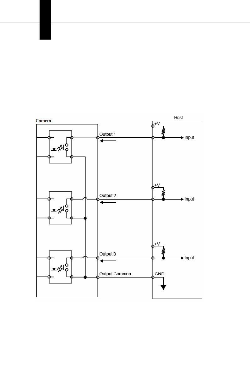
Optoisolated Outputs
The reader has optoisolated outputs that can transfer signals from the
camera to peripherals. Outputs can be configured as either NPN or PNP,
but NPN and PNP cannot be mixed in a system, because the output
common is shared by all outputs.
NPN Output for Host Input

Mounting and Wiring the Vision HAWK Smart Camera
System Components
2
Vision HAWK Smart Camera Guide 2-11
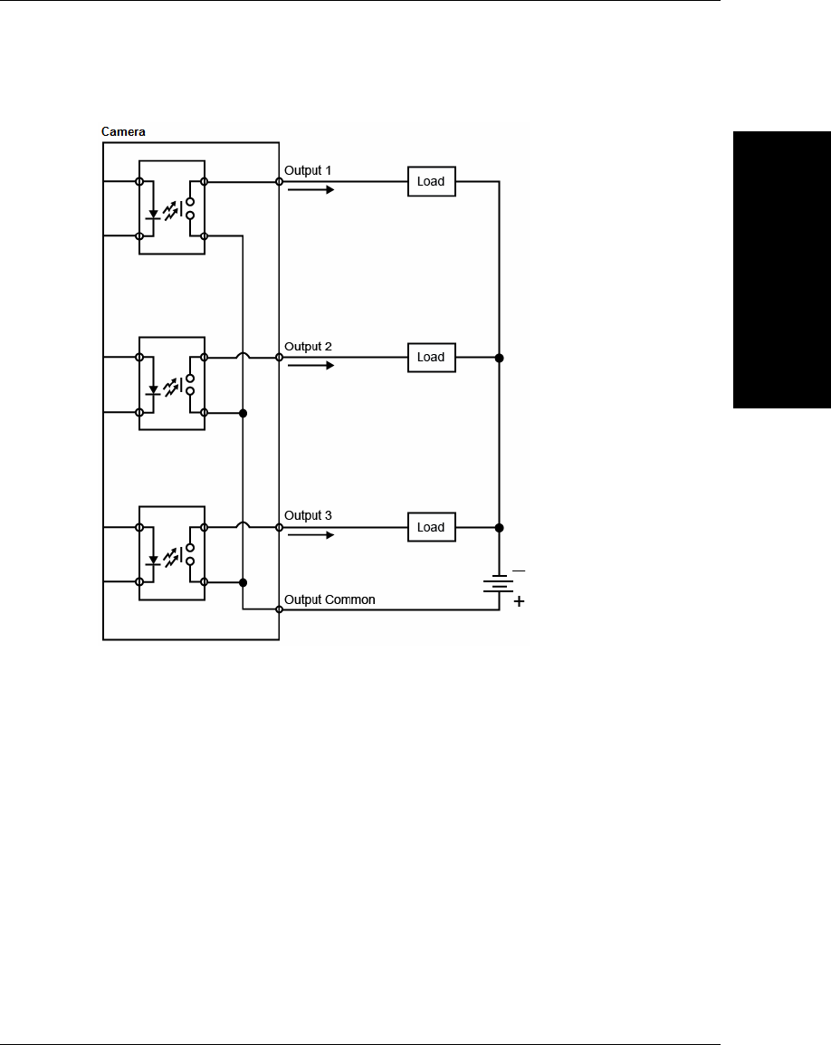
NPN Output for External Load

Chapter 2System Components
2-12 Vision HAWK Smart Camera Guide
PNP Output for Host Input
Mounting and Wiring the Vision HAWK Smart Camera
System Components
2
Vision HAWK Smart Camera Guide 2-13
PNP Output for External Load
Chapter 2System Components
2-14 Vision HAWK Smart Camera Guide
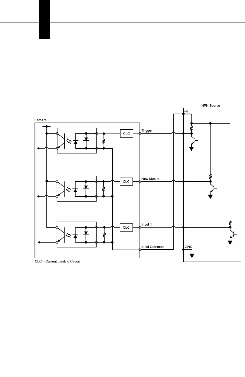
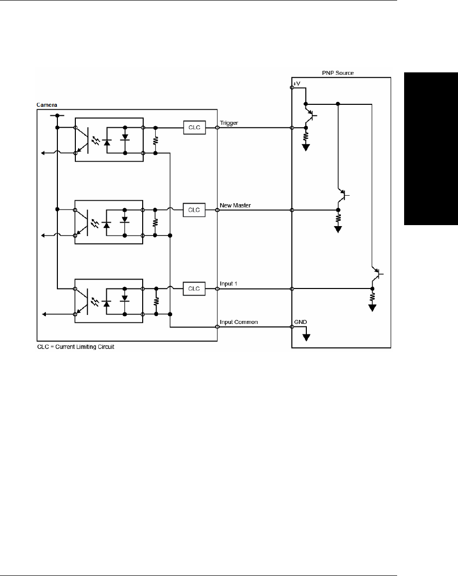
Optoisolated Inputs
All discrete inputs are optoisolated. Inputs can be configured as either
NPN or PNP, but NPN and PNP cannot be mixed in a system, because
the input common is shared by all inputs.
NPN
Mounting and Wiring the Vision HAWK Smart Camera
System Components
2
Vision HAWK Smart Camera Guide 2-15
PNP
Chapter 2System Components
2-16 Vision HAWK Smart Camera Guide
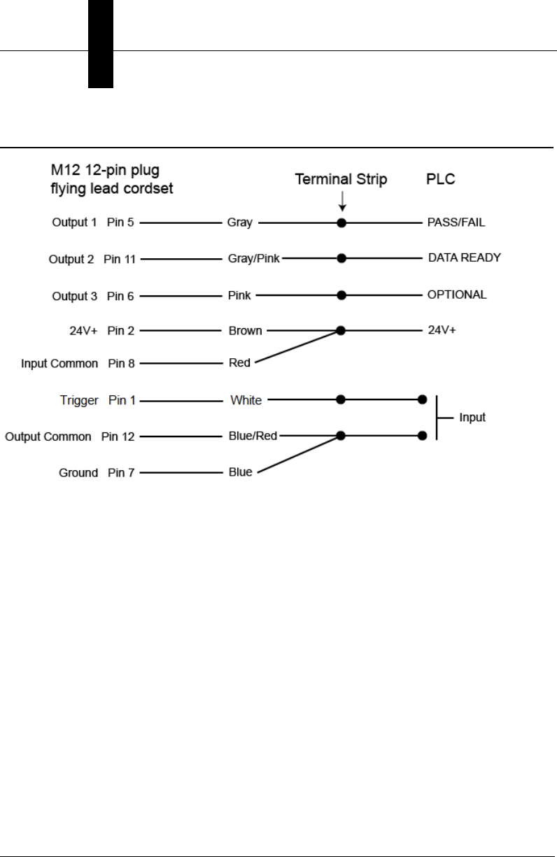
Input/Output Wiring
Ground and Shield Considerations
System Components
2
Vision HAWK Smart Camera Guide 2-17
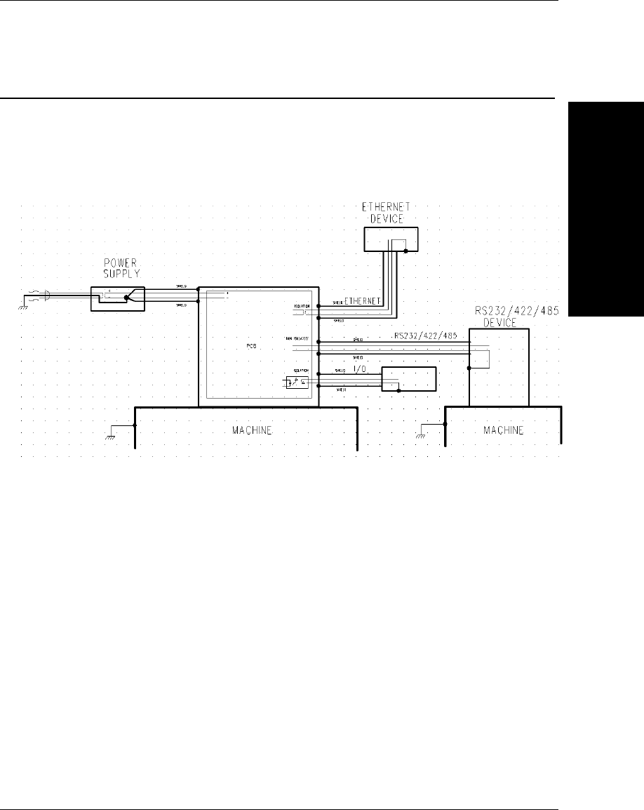
Ground and Shield Considerations
Proper grounding is necessary for operator safety, noise reduction, and
the protection of equipment from voltage transients. Buildings, including
any steelwork, all circuits, and all junction boxes must be grounded
directly to an earth ground in compliance with local and national electrical
codes.
Ground Loops
Ground loops (signal degradation due to different ground potentials in
communicating devices) can be eliminated or minimized by ensuring that
both the host, imager, and their power supplies are connected to a
common earth ground.
An earth ground is provided through the cable shields and chassis of the imager.
Vision HAWK

Chapter 2System Components
2-18 Vision HAWK Smart Camera Guide
Expected Power and Ground Connections for Proper Operation
Grounding Notes:
• Ensure that mounting bracket “Earth” is at the same potential as
power source “Earth”.
• Supply “Return” and “Earth” ground must be stable, low-impedance
reference points.
• “2-Terminal Power Supply” must still provide an “Earth” connection to
the imager.
• “Signal Ground” can be used for communications and/or discrete signal
ground reference. It must not be used as Power Ground or Earth
Ground.
Power Requirements
System Components
2
Vision HAWK Smart Camera Guide 2-19
Power Requirements
Refer to Table 2-3 when determining the power supply requirements for
your camera.
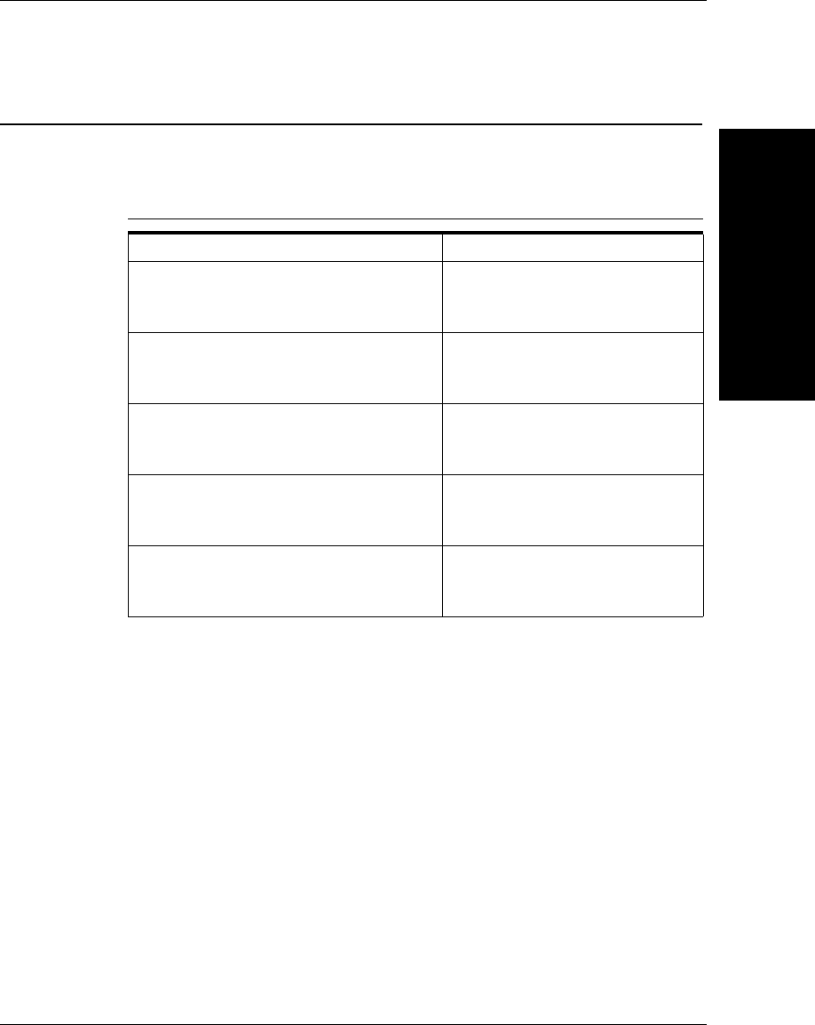
TABLE 2–3. Camera Power Requirements
Component
Vision HAWK Smart Camera, CCD,
SXGA
5-28VDC, 200mV p-p max ripple,
170mA at 24VDC (typ.)
15.5 watts (max.)
Vision HAWK Smart Camera, CMOS,
SXGA
5-28VDC, 200mV p-p max ripple,
135mA at 24VDC (typ.)
13 watts (max.)
Vision HAWK C-Mount Smart Camera,
CCD, SXGA
5-28VDC, 200mV p-p max ripple,
130mA at 24VDC (typ.)
7 watts (max.)
Vision HAWK C-Mount Smart Camera,
CMOS, WVGA
5-28VDC, 200mV p-p max ripple,
105mA at 24VDC (typ.)
4 watts (max.)
Vision HAWK C-Mount Smart Camera,
CMOS, WUXGA
5-28VDC, 200mV p-p max ripple,
140mA at 24VDC (typ.)
5.7 watts (max.)
Chapter 2System Components
2-20 Vision HAWK Smart Camera Guide
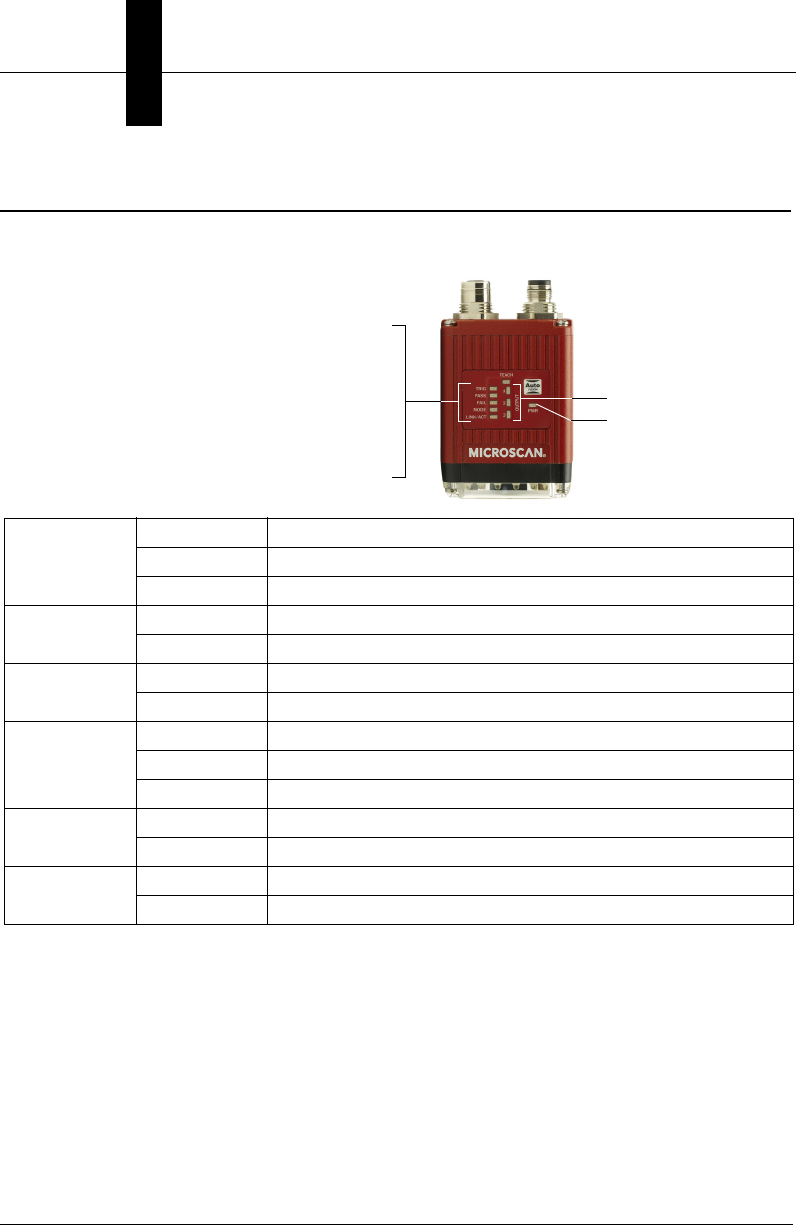
Status Indicators
The top of the Vision HAWK Smart Camera has multiple LEDs that indicate
different trigger, inspection, camera, communication, and power states.
Additional User Feedback
• Green Flash – A green flash from the front of the unit indicates a Good Read.
• Red X Targeting Pattern – The red X targeting pattern from the front of
the unit allows the user to center an object in the camera’s field of view.
• Beeper – The beeper is an audible verification that either a Pass or a
Fail has occurred.
TRIG
On Steady Continuous Trigger
Off Waiting for Trigger Event
On Flashing Trigger Event
PASS/FAIL On Active State
Off Inactive State
MODE On Steady Unit Ready
Off Unit Not Ready
LINK/ACT
On Steady Link Established
Off No Link/Activity
On Flashing Link Established and Activity on Link
PWR On Power On
Off No Power Applied to Unit
OUTPUTS On Signal Sent to External Output
Off No Signal Sent to External Output
TRIG = Trigger Status
PASS/FAIL = Inspection Status
MODE = Camera Status
LINK/ACT = Link Activity Status
Power Status
Outputs 1, 2, 3
AutoVISION Button
System Components
2
Vision HAWK Smart Camera Guide 2-21
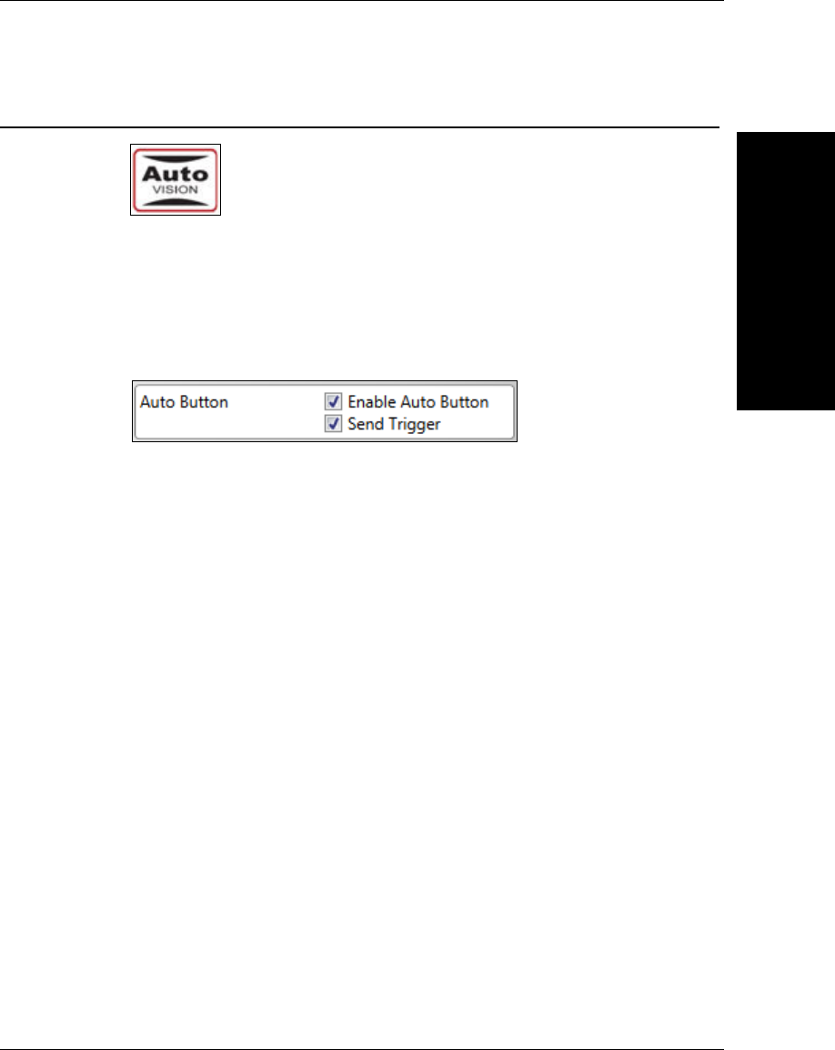
AutoVISION Button
The AutoVISION Button has three positions, selectable by the length of
time the button is held down, and indicated by one, two, or three beeps
and LED flashes in succession. It can also be used to send a trigger
signal when Send Trigger is checked in AutoVISION software’s Connect
view. When the trigger functionality is enabled, pushing the AutoVISION
Button triggers the camera to capture an image.
1st Position: Red Targeting Pattern
The first AutoVISION Button position turns the targeting system on.
This overrides any other targeting modes that have been configured.
2nd Position: Auto Calibration
The second AutoVISION Button position starts the Auto Calibration
process, which selects the appropriate photometry and focus settings
for the camera. The selected values are then saved for power-on.
3rd Position: Teach
The third AutoVISION Button position sets the Match String to the
next OCR string or symbol data that is decoded.
Chapter 2System Components
2-22 Vision HAWK Smart Camera Guide
Setting Up a Job in AutoVISION
AutoVISION is a critical component of the Vision HAWK’s functionality.
Designed for use with the Vision HAWK, AutoVISION provides an intuitive
interface, step-by-step configuration, and a library of presets that allow
easy setup and deployment. For more complex vision applications, the
system can be upgraded from AutoVISION to Visionscape.
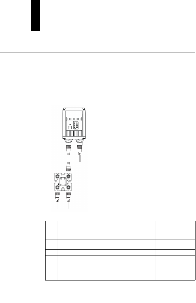
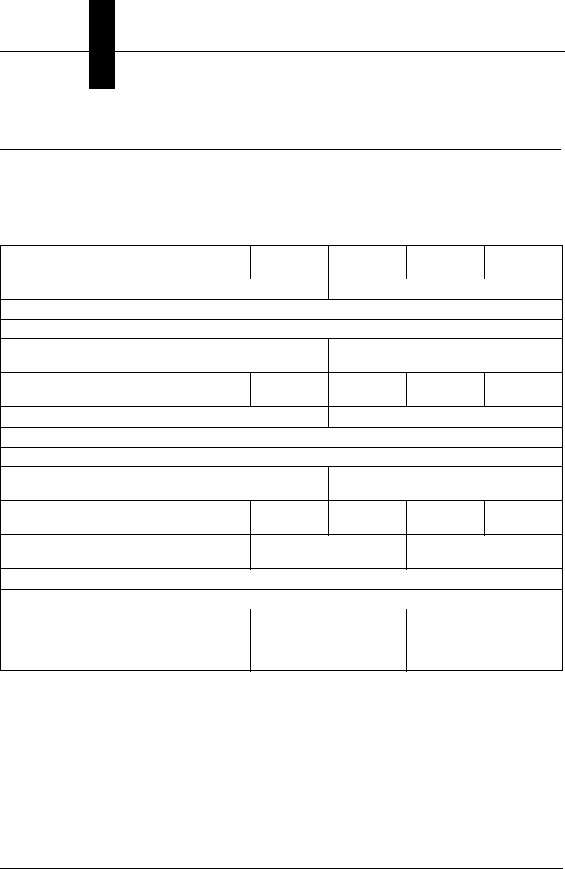
1. Configure Vision HAWK hardware.
Item Description Part Number
1Vision HAWK Smart Camera GMV-6800-XXXXG
2QX-1 Interface Device 98-000103-02
3Cordset, Common, M12 12-pin Plug to M12 12-pin
Socket, 1 m 61-000162-01
4Cordset, Host, Serial, M12 12-pin Plug to DB9, 1 m 61-000152-01
5Cordset, Host, Serial, M12 12-pin Socket to DB9, 1 m 61-000153-01
6Power Supply, M12 12-pin Socket, 1.3 m 97-000003-01
7Cordset, Host, Ethernet, M12 8-pin Plug to RJ45, 1 m 61-000160-01
8Trigger, M12 4-pin Plug, NPN, Dark On, 2 m 99-000020-02
Note: Additional cables available in the Microscan Product Pricing Catalog.
1
3
8
6
7
2
See Appendix A, Connector Pinouts, for
Vision HAWK pin assignments.
Setting Up a Job in AutoVISION
System Components
2
Vision HAWK Smart Camera Guide 2-23
– Mount the camera as required by the application.
– Connect the Ethernet cable from "B" on the camera to the
network.
– Connect the power supply to "3" on the QX-1.
– Connect the photo sensor to "T" on the QX-1.
– Connect the "Common" cable to "2" on the QX-1 and "A" on the
camera.
– Plug in the power supply.
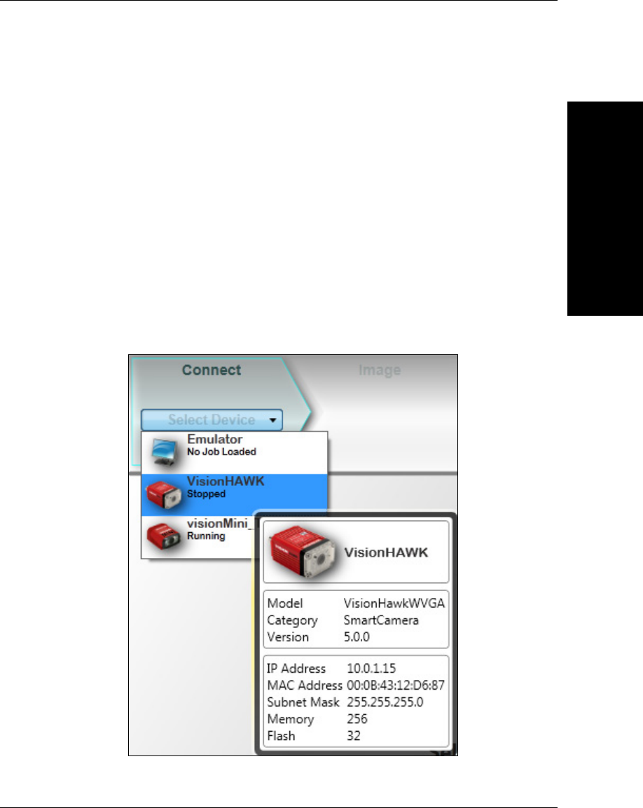
2. Select your Vision HAWK in the AutoVISION Connect view, create a
job, and adjust camera settings.
AutoVISION's Connect view allows you to select your device and
configure its settings, and to create a new job. The Select Device
dropdown menu provides a list of available devices. Hover the mouse
over a device to see its details.
Chapter 2System Components
2-24 Vision HAWK Smart Camera Guide
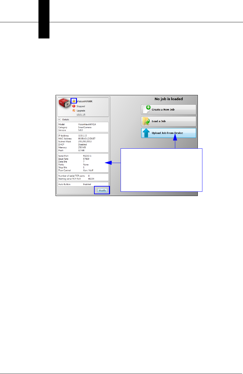
Click the lock icon to take control of the camera. When you have
control of the camera, the Modify button will appear beneath the
camera settings. Click the Modify button to adjust camera settings.
Note: The default IP address of the camera is: 192.168.0.10. Be sure
your PC is on the same subnet (192.168.0.100, for example).
Important: When modifying camera settings, you will need to enter a
username and password for the camera if a password has been defined.
Modify camera settings in the
Details area at the left of the
Connect view.
Create, Load, or Upload a job
using the buttons in the center
of the Connect view.

Setting Up a Job in AutoVISION
System Components
2
Vision HAWK Smart Camera Guide 2-25
Once you have selected your camera, adjusted its settings, and
created a new job, you will move to the Image view. This view allows
you to Auto Calibrate the camera, and to manually adjust the
camera's Exposure, Gain, and Focus, and also to set the Lighting
Mode (On, Off, or Strobe).
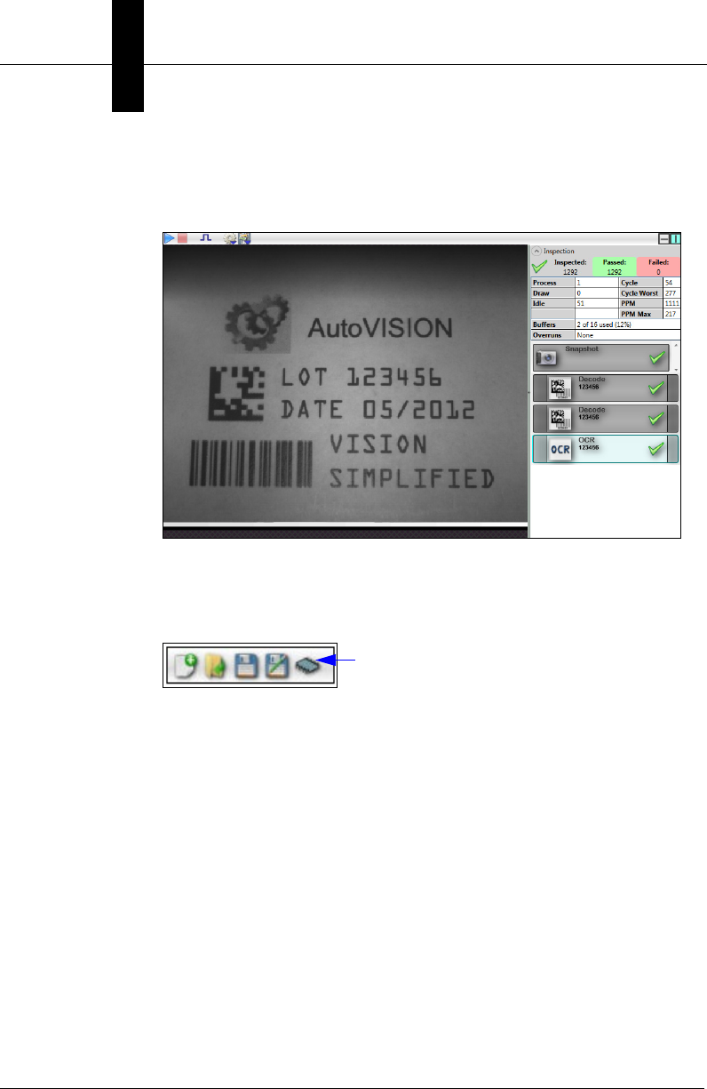
3. Edit the Job in AutoVISION.
After you have created a new job, loaded a job from your PC, or
uploaded a job from the camera, you will proceed to the Edit view to
refine your machine vision job. The Camera parameters below the
captured image allow you to set Gain, Exposure, Focus, Trigger, and
Lighting. Inspection Outputs options allow you to connect your job to
the outside world. This is also the view where you can add multiple
tools to the job. The tool icons are located above the main view area.
Chapter 2System Components
2-26 Vision HAWK Smart Camera Guide
4. Run the Job in AutoVISION.
Going to the Run view will automatically download your job to the
camera and start it running.
5. Save the Job.
Click the Save to Camera icon on the File menu bar to save the job
to the Vision HAWK.

Trigger Debounce
System Components
2
Vision HAWK Smart Camera Guide 2-27
Trigger Debounce
Trigger Debounce
is the ability of the system to accomodate switching noise on a trigger state
change – a common issue with relays that have some intermittent contact while engaging.
Trigger overruns (when the vision system is triggered faster than the device can process)
can be avoided by increasing the “debounce” time in the camera definition file located in
the C:\Microscan\Vscape\Drivers\CamDefs directory.
The IO Line Debounce High Time and IO Line Debounce Low Time can be added to the
file as in the example below. The default debounce time is 1 ms (1,000 μs).
// Camera Definition File
// Version: 1.10
Camera Name VisionHAWK 752x480 CMOS // Name Displayed
in Camdef Selection Dialog
Digitizer Type 4000 // Number
associated with VisionHawk CMOS Camera
Stride 752 // Image Width
Rows 480 // Image Height
X Offset 0 // Image X Offset
Y Offset 0 // Image Y Offset
Bits Per Pixel 8 // Bits that represent Pixel Value
Pixel Type 0 // Type of Pixel: MONOCHROME=0,
COLOR_RGB=1, COLOR_BGR=2, COLOR_BAYGR8=3, COLOR_BAYRG8=4, COLOR_BAYGB8=5,
COLOR_BAYBG8=6, COLOR_HSI=7
Image Structure 1 // Pixel Organization: Packed=1, TwoPlanes =
2, ThreePlanes = 3
Async Control 1 // Controllable shutter time. Usually
using a pulse width specified in usecs
Usecs Per Frame 16667 // Fastest time to acquire a frame: 60 FPS
for VisionHawk CMOS Camera // -1 Disables timeout feature
// IO Configuration
GPIO Edit Mask 0x0000
GPIO Defaults 0x0001 // 1 General Purpose Input 3 General Purpose
Outputs
GPIO Count 4
GPIO Inputs 1
GPIO Outputs 3
Sensors 1 // One input dedicated
to Trigger signal
Strobes 0
Virtual IO 2048
IO Line Debounce High Time 2000 //usecs
IO Line Debounce Low Time 2000 //usecs
// Focus & Photometry Ranges
Gain Dflt 20
Gain Min 0
Gain Max 100 // 0 to 100%
Exp Dflt 400
Exp Min 25
Exp Max 100000 // 1/10 to 1/40,000
Focus Dflt 400
Focus Min 100
Focus Max 4000 // 1 to 40 inches
// Lens Configuration
C-Mount 0 // 0 = false, 1 = true

Chapter 2System Components
2-28 Vision HAWK Smart Camera Guide

Vision HAWK Smart Camera Guide 3-1
3
Optics and Lighting
3
CHAPTER 3 Optics and Lighting
This section describes the optical and illumination characteristics of the
Vision HAWK Smart Camera.
Chapter 3Optics and Lighting
3-2 Vision HAWK Smart Camera Guide
Optics
The Vision HAWK Smart Camera is available with a built-in CMOS sensor
or CCD sensor.
Optics Specifications
Part Number GMV-6800-
1100G
GMV-6800-
1200G
GMV-6800-
1300G
GMV-6800-
1110G
GMV-6800-
1210G
GMV-6800-
1310G
Sensor
1/3”, SXGA (1280 x 960) CCD, up to 20 fps 1/3”, WVGA (752 x 480) CMOS, up to 60 fps
Sensor Color
Monochrome
Focal Range
1” (33 mm) to ∞ (liquid lens autofocus)
Shutter
Global Shutter; Exposure: 6µs to 100ms
(1/150,000 to 1/10) Default = 666µs (1/1,500)
Global Shutter; Exposure: 25µs to 100ms
(1/40,000 to 1/10) Default = 400µs (1/2,500)
Part Number GMV-6800-
1102G
GMV-6800-
1202G
GMV-6800-
1302G
GMV-6800-
1112G
GMV-6800-
1212G
GMV-6800-
1312G
Sensor
1/3”, SXGA (1280 x 960) CCD, up to 20 fps 1/3”, WVGA (752 x 480) CMOS, up to 60 fps
Sensor Color
Monochrome
Focal Range
1” (33 mm) to ∞ (liquid lens autofocus)
Shutter
Global Shutter; Exposure: 6µs to 100ms
(1/150,000 to 1/10) Default = 666µs (1/1,500)
Global Shutter; Exposure: 25µs to 100ms
(1/40,000 to 1/10) Default = 400µs (1/2,500)
Part Number GMV-6800-
1000G
GMV-6800-
1002G
GMV-6800-
1010G
GMV-6800-
1012G
GMV-6800-
1030G
GMV-6800-
1032G
Sensor
1/3”, SXGA (1280 x 960)
CCD, up to 20 fps
1/3”, WVGA (752 x 480)
CMOS, up to 60 fps
2/3”, WUXGA (2048 x 1088)
CMOS, up to 48 fps
Sensor Color
Monochrome
Focal Range
Depends on lens
Shutter
Global Shutter; Exposure:
6µs to 100ms (1/150,000 to
1/10) Default = 666µs
(1/1,500)
Global Shutter; Exposure:
25µs to 100ms (1/40,000 to
1/10) Default = 400µs
(1/2,500)
Global Shutter; Exposure:
25µs to 100ms (1/40,000 to
1/10) Default = 400µs
(1/2,500)

Lens Substitution
Optics and Lighting
3
Vision HAWK Smart Camera Guide 3-3
Lens Substitution
The following procedure will change the appropriate settings in the Vision
HAWK to allow the camera to focus properly after the lens has been
changed. Please note that the Vision HAWK camera will use default
lookup tables for the focus when the lens selection is changed, so the
actual focus distances may not be as accurate as the lens that was
shipped with the unit that was factory calibrated. Since default lookup
tables are used, the Vision HAWK may not focus over the full focus range
that is normally seen when using the factory calibrated lens.
After the lens has been changed via the parameters below, the new
values will take effect the next time that the lens focus is modified.
1. Boot the Vision HAWK Smart Camera.
2. Connect to the Vision HAWK via Telnet using the IP address of the
camera.
3. Send the following command after the Vision HAWK has booted:
stopAll
The response should be "value = 1 = 0x1".
4. Send the following command:
GetCurrentLense()
One of these 3 responses will be seen:
1 = 15deg
2 = 30deg
3 = 45deg
5. After camera has booted, send the following command (choose the
appropriate command based on the lens):
SetCurrentLense(1)(to change to 15 degree lens)
The response should be:
"Now Set to 1 = 15deg"

Chapter 3Optics and Lighting
3-4 Vision HAWK Smart Camera Guide
"value = 0 = 0x0"
SetCurrentLense(2)(to change to 30 degree lens)
The response should be:
"Now Set to 2 = 30deg"
"value = 0 = 0x0"
SetCurrentLense(3)(to change to 45 degree lens)
The response should be:
"Now Set to 3 = 45deg"
"value = 0 = 0x0"
6. Send the following command:
startAll
The response should be "value = 1 = 0x1"
Illumination
Optics and Lighting
3
Vision HAWK Smart Camera Guide 3-5
Illumination
The standard version of the Vision HAWK Smart Camera has built-in
lighting (red LEDs for SXGA models and white LEDs for QXGA models).
The LEDs can be configured to operate in multiple modes – Continuous,
Strobe, and Off.
Warning: Running a red LED board on a camera with a white LED color
profile will damage both the board and the camera.
Important:
The Vision HAWK C-Mount (GMV-6800-1000G, GMV-6800-1002G,
GMV-6800-1010G, GMV-6800-1012G, GMV-6800-1030G, GMV-6800-1032G)
does not have built-in lighting. The Machine Vision Lighting Principles on
the following page provide some suggestions for how to determine the
appropriate external lighting for your application.
Lighting Specifications
Part Number GMV-6800-
1100G
GMV-6800-
1200G
GMV-6800-
1300G
GMV-6800-
1110G
GMV-6800-
1210G
GMV-6800-
1310G
GMV-6800-
1102G
GMV-6800-
1202G
GMV-6800-
1302G
GMV-6800-
1112G
GMV-6800-
1212G
GMV-6800-
1312G
Illumination Red @ 617nm
Part Number
GMV-6800-
1000G
GMV-6800-
1002G
GMV-6800-
1010G
GMV-6800-
1012G
GMV-6800-
1030G
GMV-6800-
1032G
Illumination External Illumination Required

Chapter 3Optics and Lighting
3-6 Vision HAWK Smart Camera Guide
Machine Vision Lighting Principles
Proper lighting is critical to the success of a machine vision
application. Depending on the requirements of your application, you
may also need to add external lighting from Microscan’s NERLITE
family of machine vision lighting products.
Consider the following when setting up your application:
– Is the surface of the object flat, slightly bumpy, or very bumpy?
– Is the surface matte or shiny?
– Is the object curved or flat?
– What is the color of the object or area being inspected?
– Is the object moving or stationary?
Machine vision lighting should maximize contrast of the areas or features
being inspected while minimizing the contrast of everything else.
Before correct lighting After correct lighting with
a NERLITE CDI Illuminator
Illumination
Optics and Lighting
3
Vision HAWK Smart Camera Guide 3-7
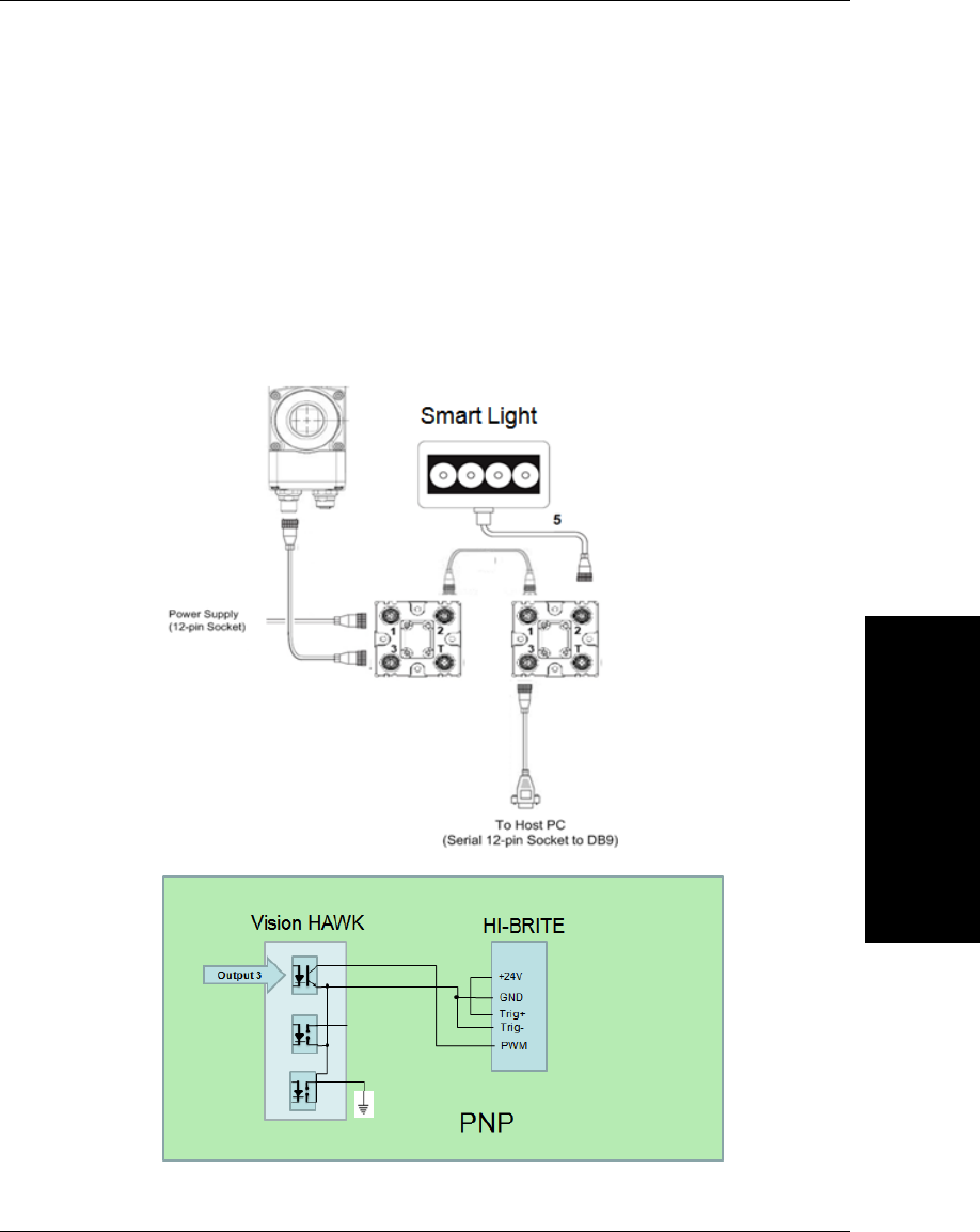
External Illumination Control
The Vision HAWK C-Mount Smart Camera supports external lighting with
Microscan’s NERLITE Smart Series lights. The diagram below
demonstrates how the camera and light can be configured with two QX-1
interface devices. The light is controlled using the Lighting control in the
Camera configuration settings of AutoVISION software.
The camera’s trigger is synchronized with the light to create a strobe
effect for reliable image acquisition.

Chapter 3Optics and Lighting
3-8 Vision HAWK Smart Camera Guide

Vision HAWK Smart Camera Guide 4-1
4
Using EtherNet/IP
4
CHAPTER 4 Using EtherNet/IP
This section provides information necessary for using the Vision HAWK in
an EtherNet/IP environment.

Chapter 4Using EtherNet/IP
4-2 Vision HAWK Smart Camera Guide
Vision HAWK EtherNet/IP
Throughout this document, EtherNet/IP may be referred to as “EIP”, and
Vision HAWK may be abbreviated “VH”. The EIP interface version
described here is 1.1. This version number is associated with the EIP
interface for Microscan’s Device Type of 100, Machine Vision Smart
Cameras. It is not the software version of AutoVISION, Visionscape, or
Vision HAWK firmware.
Overview
The EIP interface will be identified as Vendor Specific (100). The interface
is designed to support Class 1 Implicit IO data exchange, and Class 3
Explicit messages for serial commands not accessible with Implicit
messaging.
Necessary Tools
The following tools are helpful for configuring the EIP:
• AutoVISION and FrontRunner
• EtherNet/IP Messaging Tool – can be a PLC or Software Tool, must
be capable ofsending explicit messages and establishing Class 1
connections. EIPScan from Pyramid Solutions is an example of such
a tool.
• Terminal emulation or serial communication tool that can connect to
serial uart and TCP socket, such as HyperTerminal or Putty.
EtherNet/IP Terms of Use
EtherNet/IP Technology is governed by the Open DeviceNet Vendor
Association, Inc (ODVA). Any person or entity that makes and sells
products that implement EtherNet/IP Technology must agree to the Terms
of Usage Agreement issued by ODVA. See www.odva.org for details.

Vision HAWK EtherNet/IP
Using EtherNet/IP
4
Vision HAWK Smart Camera Guide 4-3
EtherNet/IP Object Model
Vision HAWK uses Class 1 connected messaging to communicate most
of its data and services in a single connection.
EIP Identity
Device Type
Device type is 100, Vendor Specific, Machine Vision Smart Camera.
Vendor ID
Microscan’s ODVA Vendor ID is 1095.
Product Code
The Product Code is 6899.
Interface Revision
Major.Minor = 1.1
Connection Properties: Class 1 Implicit Messaging
Input Assembly Instance (to PLC/client): 102
Output Assembly Instance (to Vision HAWK): 114
Size: Fixed, 320 bytes in both directions
Input Trigger/Trigger Mode: Cyclic
RPI (Requested Packet Interval): Greater than 20 ms recommended. 10
ms to 3.2 s allowed.
Input Type/Connection Type:
• Point-to-Point (PLC OUT, O->T)
• Point-to-Point and Multicast (PLC IN, T->O)
Connection Priority: Scheduled
Chapter 4Using EtherNet/IP
4-4 Vision HAWK Smart Camera Guide
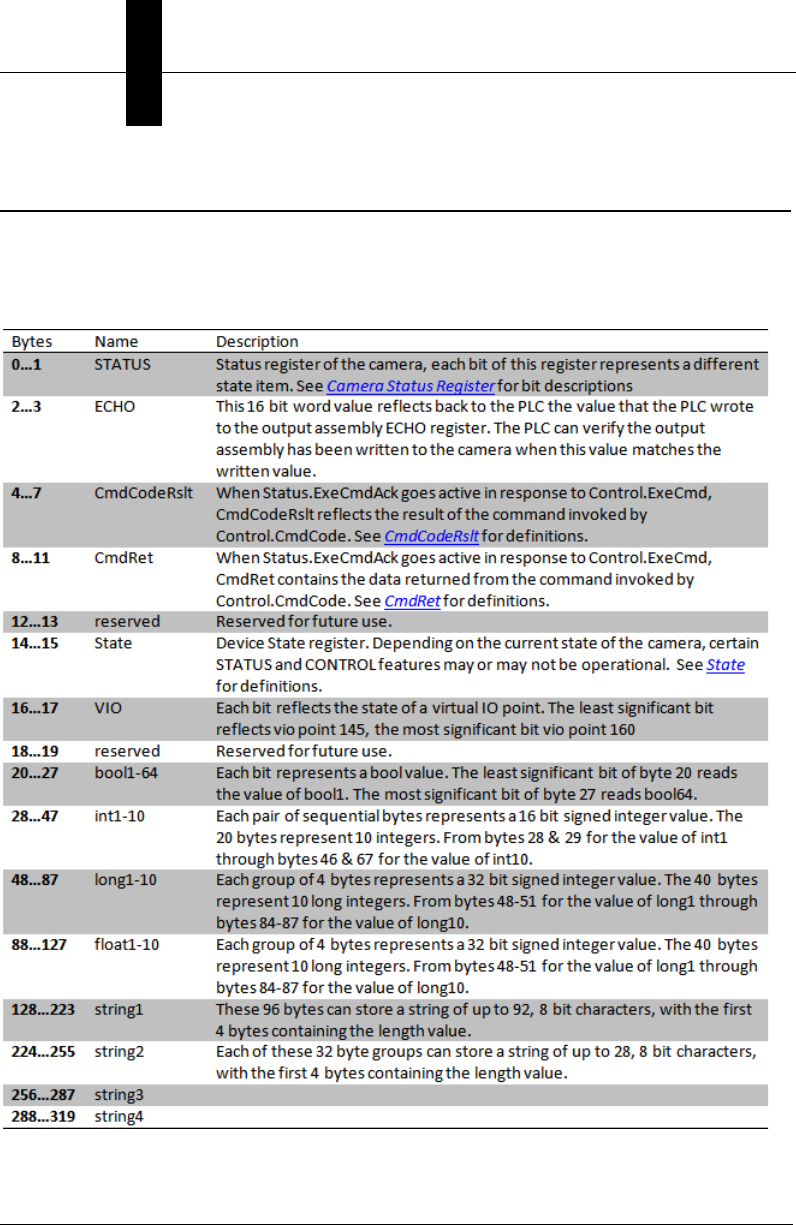
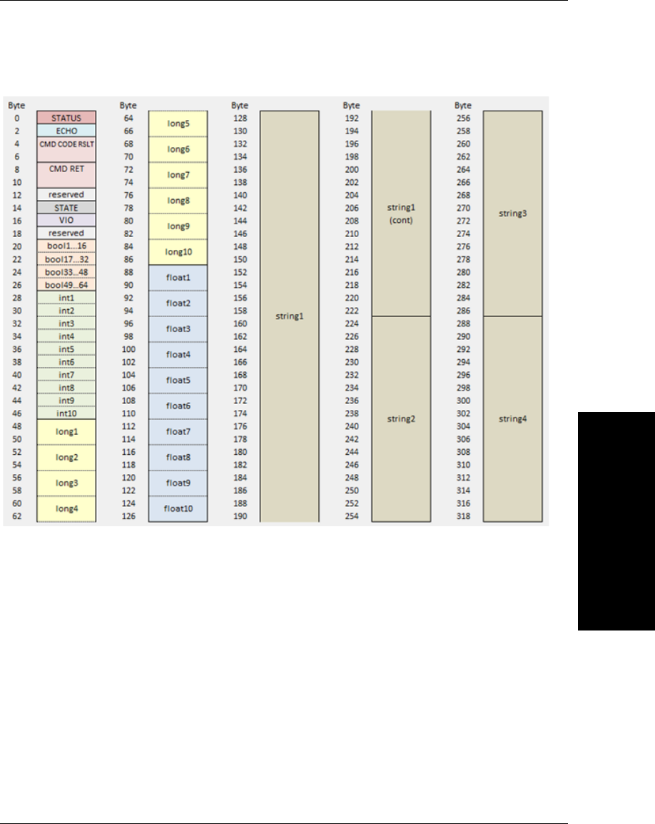
Assembly Layout
Input Assembly
The input assembly layout is described below and shown in the following diagram.
Assembly Layout
Using EtherNet/IP
4
Vision HAWK Smart Camera Guide 4-5
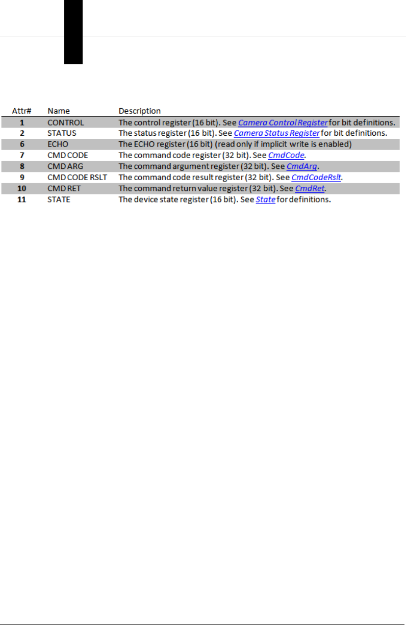
The input assembly layout is shown here:
Chapter 4Using EtherNet/IP
4-6 Vision HAWK Smart Camera Guide
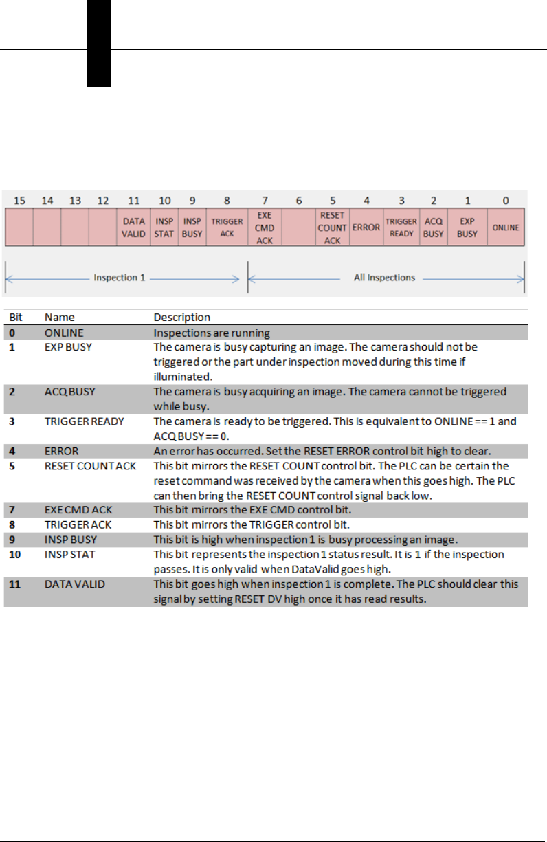
Status: Camera Status Register (16 bit)
Each bit of this register represents a different state of the camera’s operation. A high value
of 1 indicates that state is active (true).
Assembly Layout
Using EtherNet/IP
4
Vision HAWK Smart Camera Guide 4-7
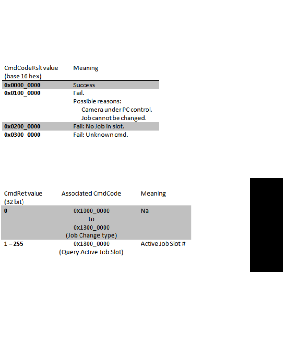
CmdCodeRslt (32 bit)
The value of CmdCodeRslt is only valid when ExeCmdAck is active (1), in response to
ExeCmd being active.
CmdRet (32 bit)
The value of CmdRet is only valid when ExeCmdAck is active (1), in response to ExeCmd
being active, and CmdCodeRslt is 0 (Success). The following chart shows which
CmdCodes return data in the CmdRet register.
Chapter 4Using EtherNet/IP
4-8 Vision HAWK Smart Camera Guide
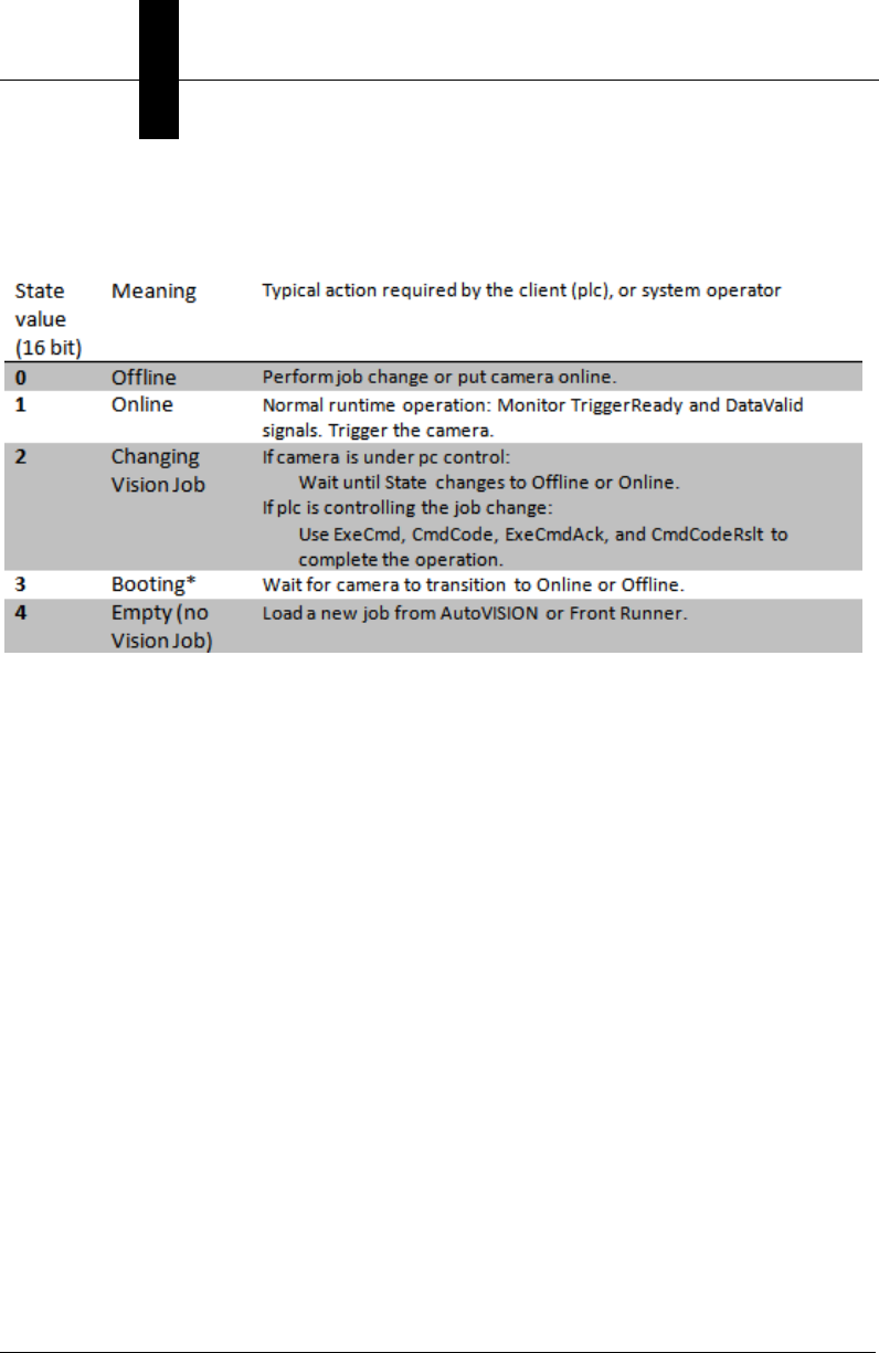
State (16 bit)
State reflects the following operational condition of the camera:
*Booting (3) State: This will rarely be seen by the plc.
Assembly Layout
Using EtherNet/IP
4
Vision HAWK Smart Camera Guide 4-9
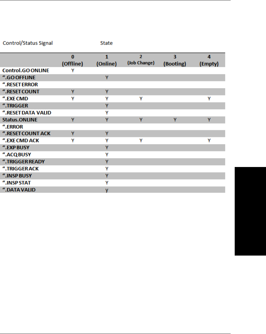
The value of State determines which Control and Status signals are available:
Where:
Y = Signal is valid for this State
Empty cell = Signal is not valid for this State
Chapter 4Using EtherNet/IP
4-10 Vision HAWK Smart Camera Guide
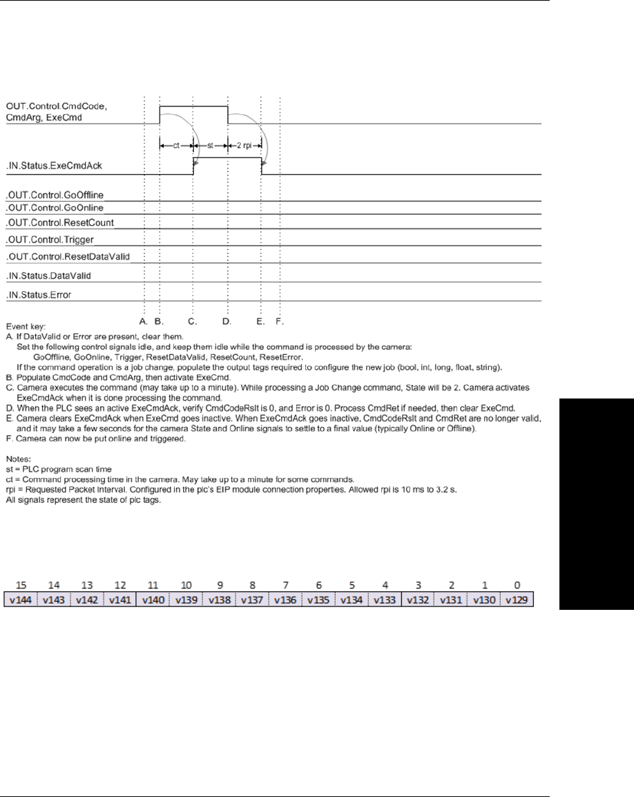
VIO Register Bits
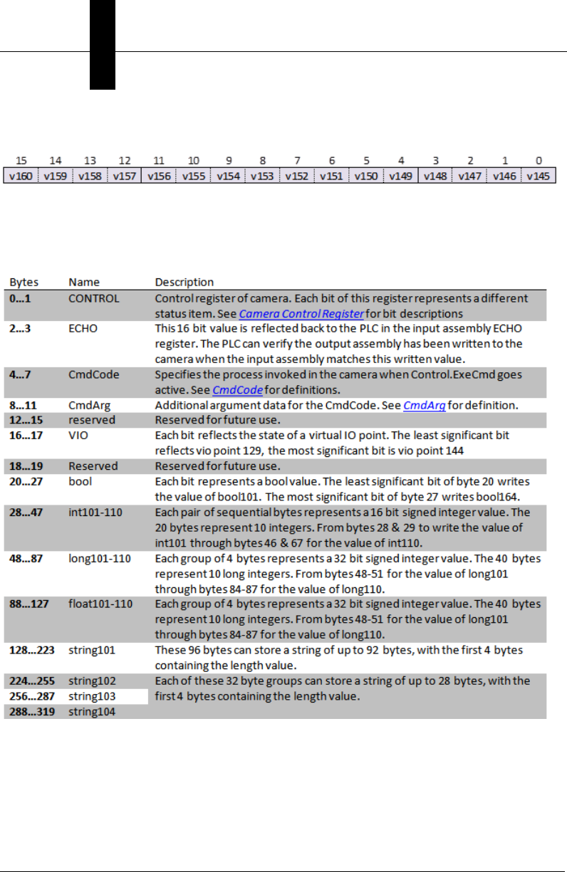
Output Assembly
The output assembly layout is described below and shown in the following diagram.
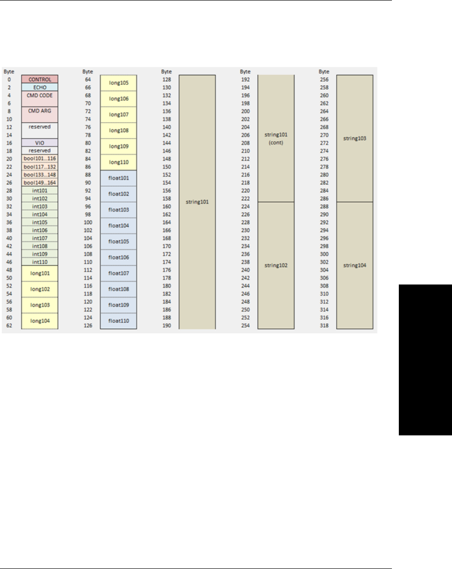
Assembly Layout
Using EtherNet/IP
4
Vision HAWK Smart Camera Guide 4-11
The output assembly layout is shown here:
Chapter 4Using EtherNet/IP
4-12 Vision HAWK Smart Camera Guide
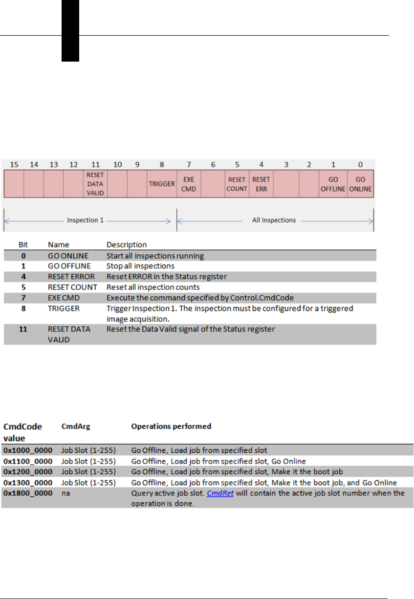
Control: Camera Control Register (16 bit)
Each bit of this register controls a function on the camera. Transitions from a low state of 0, to a
high state of 1, initiates the associate operation. The PLC should return the state of the control
bit back to 0 after it has acknowledged the camera has processed the control. Unused bits
should remain 0.
CmdCode and CmdArg (32 bit)
Specifies the process invoked in the camera when Control.ExeCmd goes active.
List of available CmdCodes, and associated CmdArg
Assembly Layout
Using EtherNet/IP
4
Vision HAWK Smart Camera Guide 4-13
CmdCode and ExeCmd Operation
VIO Register Bits

Chapter 4Using EtherNet/IP
4-14 Vision HAWK Smart Camera Guide
Connection Properties: Class 3 Explicit Messaging
All Class 1 IO assembly data and additional data are accessible via Explicit message.
Input data (Vision HAWK to PLC/Client) occupies attributes 1 to 100 of the classes. Output
data (PLC/Client to Vision HAWK) occupies attributes 101 to 200.
Service:
• Get Attribute Single (0xE)
• Set Attribute Single (0x10)
Classes:
• bool = 104 (0x68)
• int = 105 (0x69)
• long = 106 (0x6A)
• float = 107 (0x6B)
• string = 108 (0x6C)
• control/status (mixed data types) = 109 (0x6D)
Instance: 1
Attribute:
• 1 to 100 = In to PLC/Client
• 101 to 200 = Out to VH

Connection Properties: Class 3 Explicit Messaging
Using EtherNet/IP
4
Vision HAWK Smart Camera Guide 4-15
Attribute Layout
When using explicit EIP messaging, all global data objects can be read or written. Each
data type is stored in its own class object and an instance of 1 to read the global data. For
example to read float2 the EIP request would be for Service Code 14 (0xE), Class 107
(0x6B), Instance 1, Attribute 2.
The value received in response to Get Attribute Single depends on the type:
• bool will return a 16 bit word with 0 for false or 1 for true
• Ints will return a 16 bit signed integer
• longs will return a 32 bit signed integer
• floats will return a 32 bit floating point number
• strings will return a counted string. Total size of a string data item is 2048 bytes. This
includes a 4 byte “length” field followed by 2044 eight bit characters. When accessing
strings explicitly, they are not limited to the size in the IO assemblies. Eg. string3 is
limited to 28 bytes in the input assembly. If the actual string is longer than 28 bytes, it
will be truncated when reading via the assembly, but not truncated when reading the
same string via an attribute explicitly.
Chapter 4Using EtherNet/IP
4-16 Vision HAWK Smart Camera Guide
Assembly Class 109 can be used to read and write special EIP specific registers.
EIP Control/Status Signal Operation
Using EtherNet/IP
4
Vision HAWK Smart Camera Guide 4-17
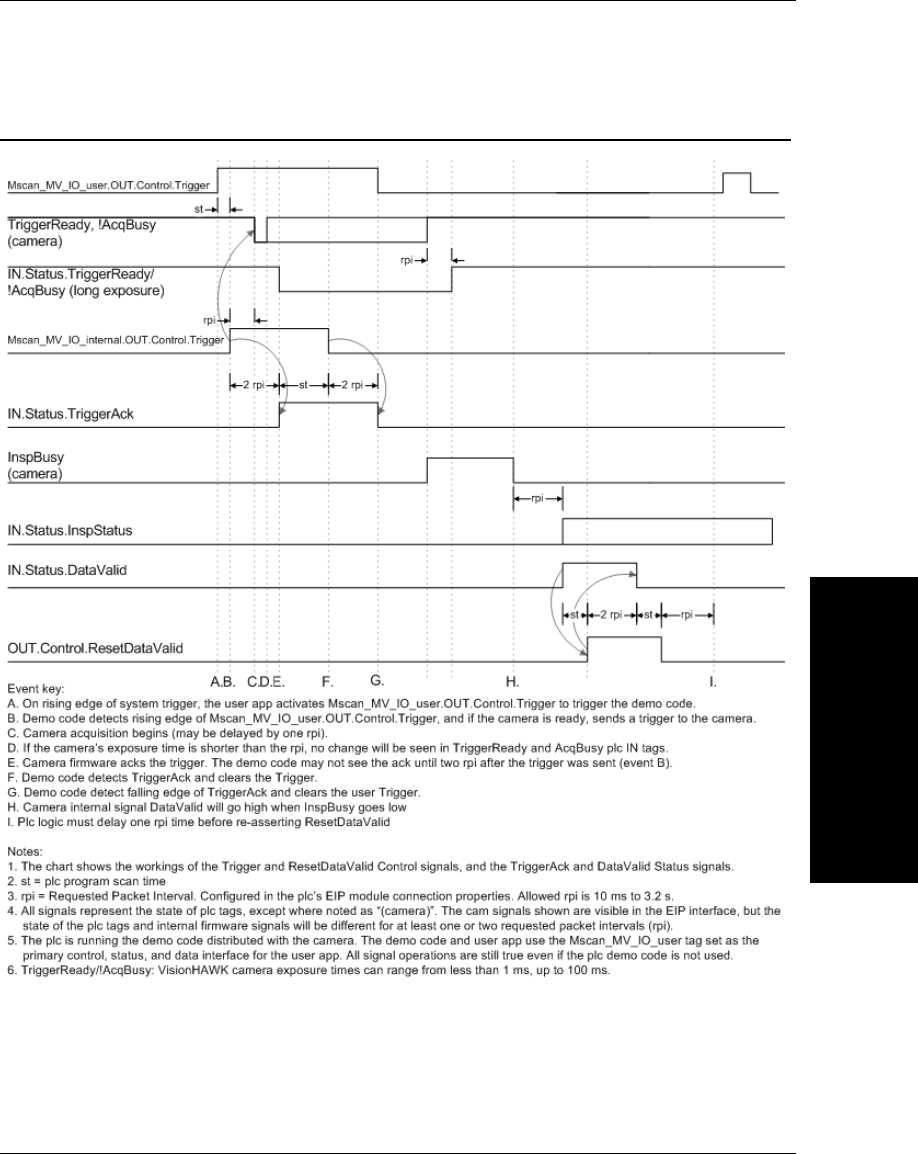
EIP Control/Status Signal Operation
Chapter 4Using EtherNet/IP
4-18 Vision HAWK Smart Camera Guide
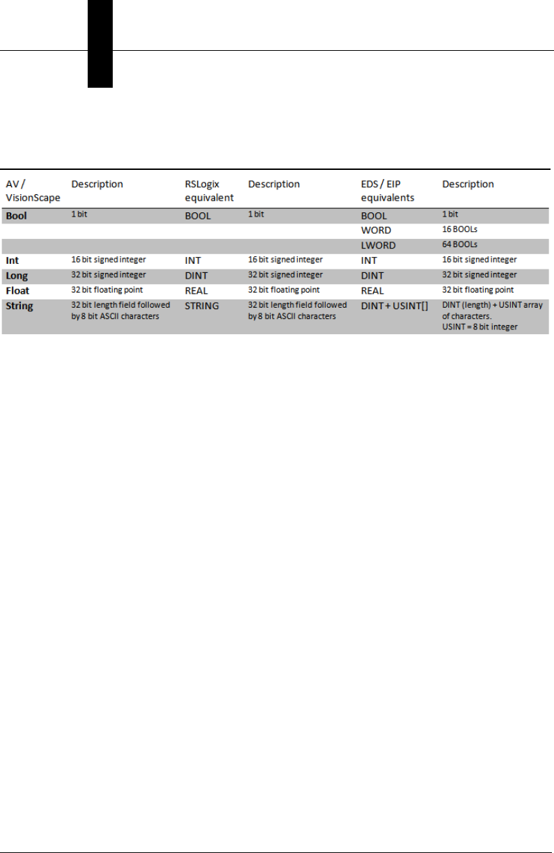
Data Type Descriptions and Equivalents in PLC and
EDS/CIP Environments
PLC Tags and Serial Command Names
Using EtherNet/IP
4
Vision HAWK Smart Camera Guide 4-19
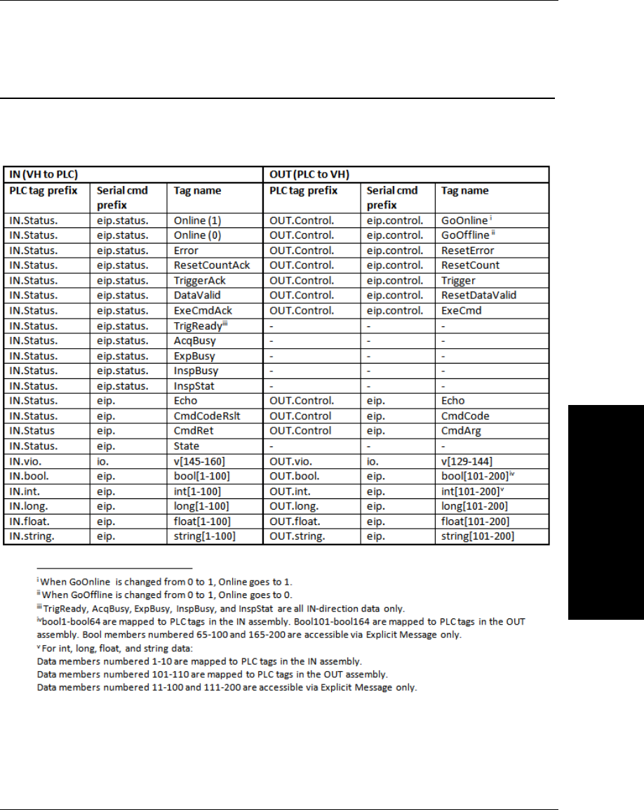
PLC Tags and Serial Command Names
PLC tags are separated into IN and OUT for data direction. Within the IN and OUT groups,
the tags are sub-divided into fixed “Status” and “Control” fields, plus user-defined linked
data fields. This table shows how PLC tag names correspond to serial commands.

Chapter 4Using EtherNet/IP
4-20 Vision HAWK Smart Camera Guide

Vision HAWK Smart Camera Guide A-1
A
Connector Pinouts
A
APPENDIX A Connector Pinouts
This section contains information about Vision HAWK Smart Camera
connectors:
• M12 12-Pin Plug on page A-2
• M12 8-Pin Socket on page A-3
Appendix AConnector Pinouts
A-2 Vision HAWK Smart Camera Guide
Vision HAWK Smart Camera Connectors
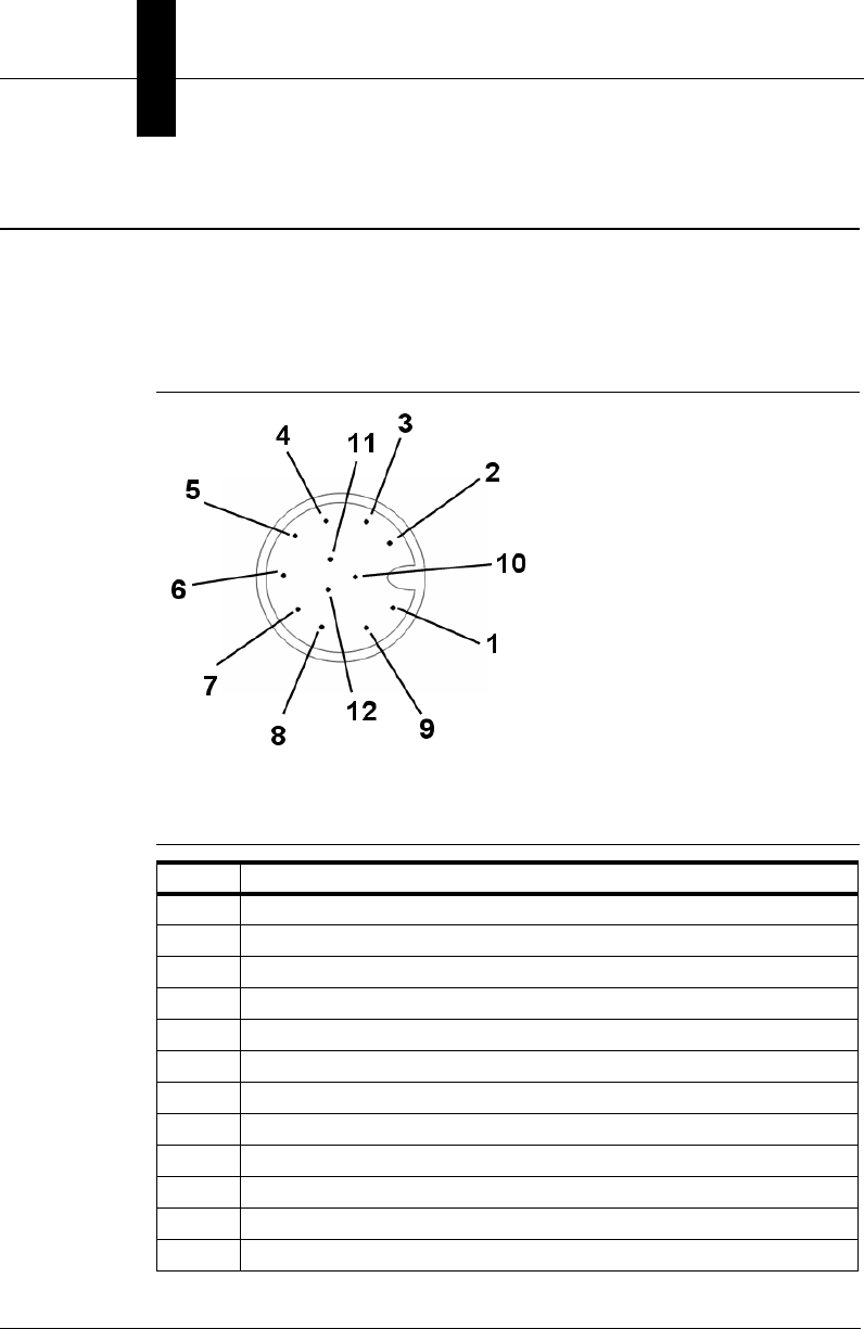
Connector A – M12 12-Pin Plug – Power, I/O, and Serial
Figure A–1 shows the M12 12-pin plug at connector A.
FIGURE A–1. Connector A – M12 12-Pin Plug
Table A–1 describes the M12 12-pin plug signals.
TABLE A–1. Connector A –
M12 12-Pin Plug
Pin Function
1 Trigger
2Power
3Default
4Input 1
5Output 1
6Output 3
7Ground
8Input Common
9Host RxD
10 Host TxD
11 Output 2
12 Output Common
Vision HAWK Smart Camera Connectors
Connector Pinouts
A
Vision HAWK Smart Camera Guide A-3
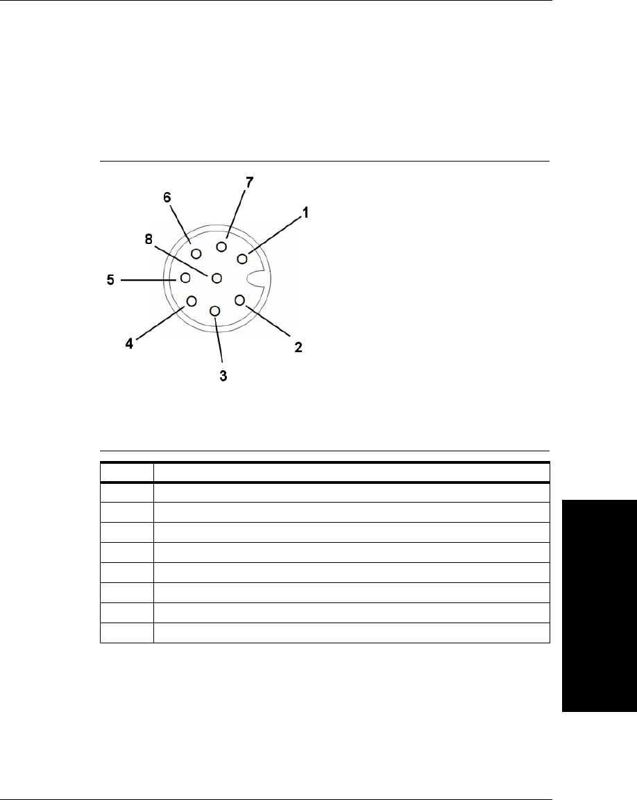
Connector B – M12 8-Pin Socket – Ethernet
Figure A-2 shows the M12 8-pin socket at connector B.
FIGURE A–2. Connector B – M12 8-Pin Socket
Table A-2 describes the M12 8-pin socket signals.
TABLE A–2. Connector B – M12 8-Pin Socket
Pin Function
1 Terminated
2Terminated
3Terminated
4TX (–)
5RX (+)
6TX (+)
7Terminated
8RX (–)

Appendix AConnector Pinouts
A-4 Vision HAWK Smart Camera Guide
Vision HAWK Smart Camera Guide B-1
B
Cable Specifications
B
APPENDIX B Cable Specifications
This section contains information about Vision HAWK Smart Camera
cables.
Note: Cable specifications are published for information only. Microscan
does not guarantee the performance or quality of cables provided by
other suppliers.
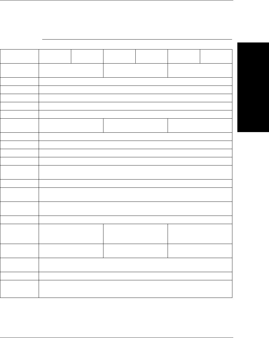
TABLE B–1. Cable Part Numbers and Descriptions
Part Number Descriptions
61-000160-01 Cable, Host, Ethernet, M12 8-pin Plug to RJ45, 1 m
61-000162-01 Cable, Common, M12 12-pin Plug to M12 12-pin
Socket, 1 m
97-000003-01 Power Supply, M12 12-pin Socket, 1.3 m
99-000020-02 Trigger, M12 4-pin Plug, NPN, Dark On, 2 m
Appendix BCable Specifications
B-2 Vision HAWK Smart Camera Guide
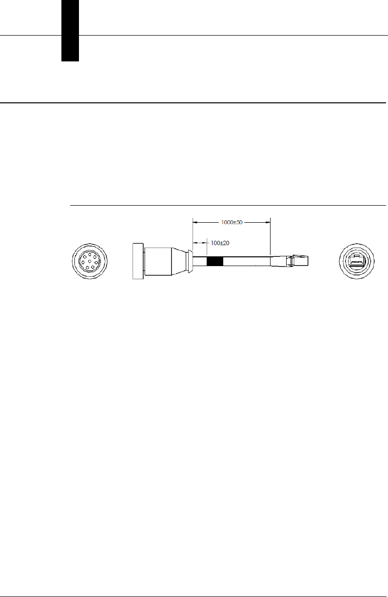
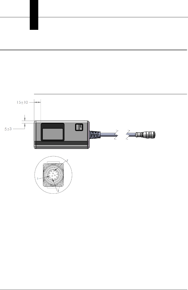
61-000160-01 Cable, Host, Ethernet, M12 8-pin Plug to RJ45, 1 m
The 61-000160-01 Cable, Host, Ethernet, M12 8-pin Plug to RJ45, 1 m is
a 1 meter cable with an 8-pin M12 Ultra-Lock connector on one end and a
standard RJ45 connector on the other end.
Figure B-1 shows the 61-000160-01 Cable, Host, Ethernet, M12 8-pin Plug
to RJ45, 1 m.
FIGURE B–1. Cable, Host, Ethernet, M12 8-pin Plug to RJ45, 1 m
Important: Be sure that the retaining clip on the RJ45 connector has
locked into place in the Ethernet receptacle on the PC and is not being
impeded by the rubber housing.
Note: A screw-down version of this cable is also available (61-000160-02).
M12 8-Pin Plug RJ45
61-000162-01 Cable, Common, M12 12-pin Plug to M12 12-pin Socket, 1 m
Cable Specifications
B
Vision HAWK Smart Camera Guide B-3
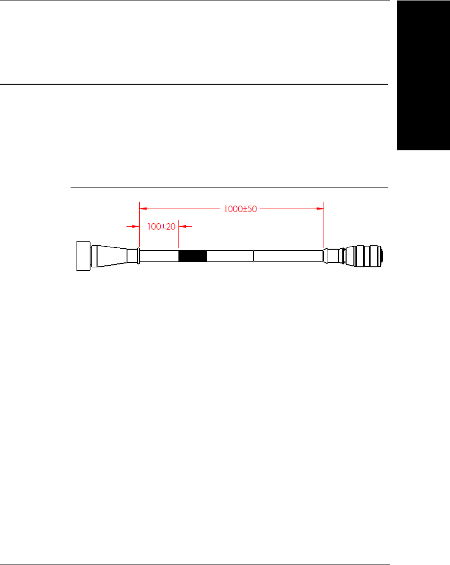
61-000162-01 Cable, Common, M12 12-pin Plug to M12 12-pin
Socket, 1 m
The 61-000162-01 Cable, Common, M12 12-pin Plug to M12 12-pin
Socket, 1 m is a 1 meter cable with a 12-pin M12 plug on one end and a
12-pin M12 socket on the other end.
Figure B-2 shows the 61-000162-01 Cable, Common, M12 12-pin Plug to
M12 12-pin Socket, 1 m.
FIGURE B–2. Cable, Common, M12 12-pin Plug to M12 12-pin Socket, 1 m
Note: A screw-down version of this cable is also available (61-000162-02).
Appendix BCable Specifications
B-4 Vision HAWK Smart Camera Guide
97-000003-01 Power Supply, M12 12-pin Socket, 1.3 m
The 97-000003-01 Power Supply, M12 12-pin Socket, 1.3 m is a 90-254
VAC, +24VDC power supply.
Figure B-3 shows the 97-000003-01 Power Supply, M12 12-pin Socket,
1.3 m.
FIGURE B–3. Power Supply, M12 12-pin Socket, 1.3 m
M12 12-Pin Socket
99-000020-02 Trigger, M12 4-pin Plug, NPN, Dark On, 2 m
Cable Specifications
B
Vision HAWK Smart Camera Guide B-5
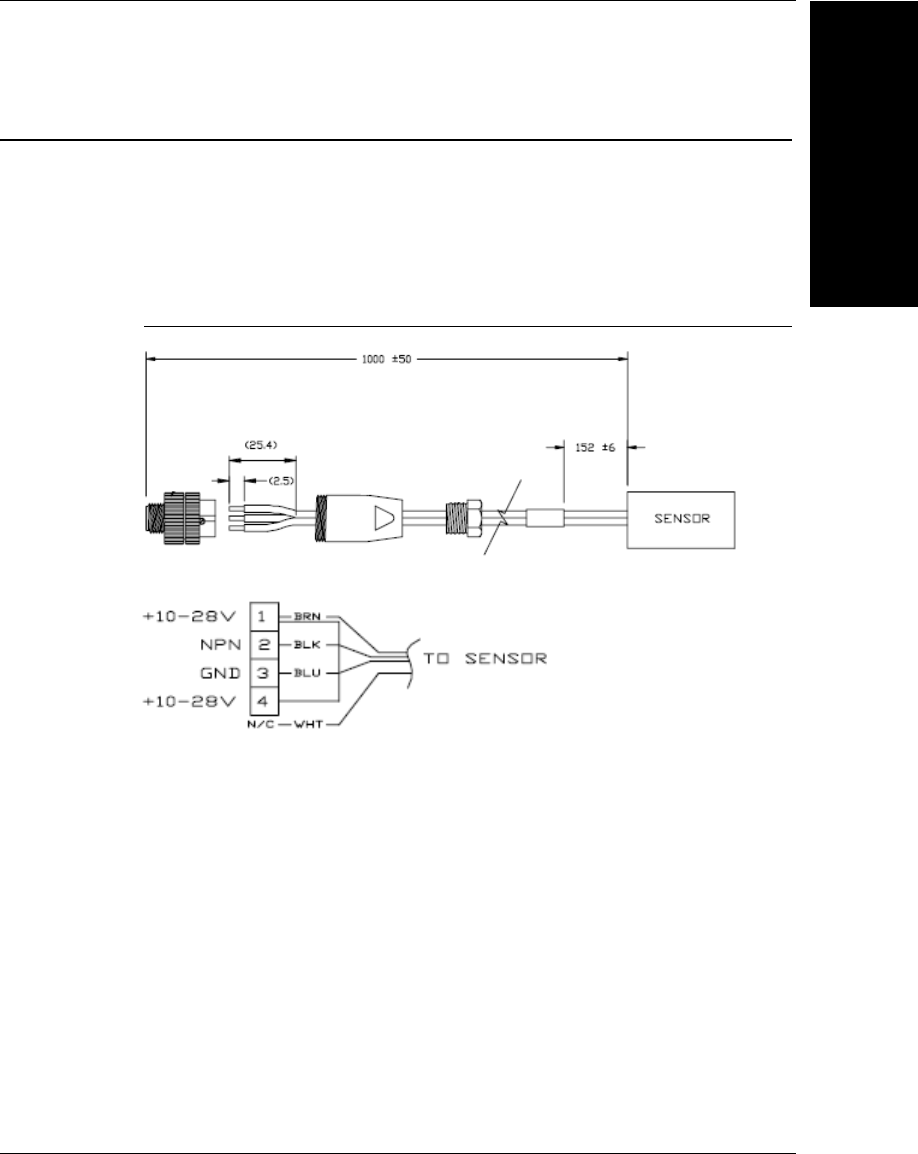
99-000020-02 Trigger, M12 4-pin Plug, NPN, Dark On, 2 m
The 99-000020-02 Trigger, M12 4-pin Plug, NPN, Dark On, 2 m is a photo
sensor with a 4-pin M12 connector.
Figure B-4 shows the 99-000020-02 Trigger, M12 4-pin Plug, NPN, Dark
On, 2 m.
FIGURE B–4. Trigger, M12 4-pin Plug, NPN, Dark On, 2 m
99-000020-02 Schematic

Appendix BCable Specifications
B-6 Vision HAWK Smart Camera Guide

Vision HAWK Smart Camera Guide C-1
C
General
Specifications
C
APPENDIX C General Specifications
This section contains specifications and dimensions for the Vision HAWK
Smart Camera and Vision HAWK C-Mount Smart Camera.

Appendix CGeneral Specifications
C-2 Vision HAWK Smart Camera Guide
TABLE C–1. General Specifications
Part Number GMV-6800-
1100G
GMV-6800-
1200G
GMV-6800-
1300G
GMV-6800-
1110G
GMV-6800-
1210G
GMV-6800-
1310G
Sensor
1/3”, SXGA (1280 x 960) CCD, up to 20 fps 1/3”, WVGA (752 x 480) CMOS, up to 60 fps
Sensor Color
Monochrome
Height
1.59” (40.5 mm)
Width
2.27” (57.6 mm)
Depth
3.79” (96.3 mm)
Weight
10 oz. (280 g)
Power
5-28VDC, 200mV p-p max ripple, 170mA at
24VDC (typ.)
5-28VDC, 200mV p-p max ripple, 135mA at
24VDC (typ.)
Connector
M12 12-pin Ultra-Lock (Connector A) and M12 8-pin Ultra-Lock (Connector B)
Lens Type
Built-In Liquid Lens (standard Vision HAWK only)
Communications
Ethernet
Illumination
High Output LEDs: .564mW, 470, 525, 617nm
Laser Output
5.0mW max.; Type: Laser diode; Output Wavelength: 655nm nominal; Operating Life:
50,000 hours @ 25° C; Safety Class: Class 1 Visible Laser
Indicators
LEDs: Trigger, Pass, Fail, Mode, Power, Network Activity, I/O; Green Flash: Pass; Red X:
Target
Discrete I/O
Learn/Trigger: Bi-directional, optoisolated, 4.5–28V rated, (13mA at 24VDC); Outputs (1, 2,
3): Bi-directional, optoisolated, 1–28V rated, (ICE <100mA at 24VDC, current limited by user)
Image
Acquisition
Progressive scan, square pixel
Focal Range
1” (33 mm) to ∞ (liquid lens autofocus - standard Vision HAWK only)
Shutter
6µs to 100ms (1/150,000 to 1/10) Default =
666µs (1/1,500)
25µs to 100ms (1/40,000 to 1/10) Default =
400µs (1/2,500)
Operating
Temperature
0° to 45° C (32° to 113° F) 0° to 50° C (32° to 122° F)
Storage
Temperature
–29° to 70° C (–20° to 158° F)
Humidity
Up to 90% (non-condensing)
Compliance
CDRH, FCC, UL/cUL, CE (General Immunity for Light Industry: EN 55024:1998 ITE
Immunity Standard; Radiated and Conducted Emissions of ITE Equipment: EN 55022:98
ITE Disturbances), CB, BSMI

General
Specifications
C
Vision HAWK Smart Camera Guide C-3
TABLE C–1. Specifications (Continued)
Part Number GMV-6800-
1102G
GMV-6800-
1202G
GMV-6800-
1302G
GMV-6800-
1112G
GMV-6800-
1212G
GMV-6800-
1312G
Sensor
1/3”, SXGA (1280 x 960) CCD, up to 20 fps 1/3”, WVGA (752 x 480) CMOS, up to 60 fps
Sensor Color
Monochrome
Height
1.59” (40.5 mm)
Width
2.27” (57.6 mm)
Depth
3.79” (96.3 mm)
Weight
10 oz. (280 g)
Power
5-28VDC, 200mV p-p max ripple, 170mA at
24VDC (typ.)
5-28VDC, 200mV p-p max ripple, 135mA at
24VDC (typ.)
Connector
M12 12-pin Ultra-Lock (Connector A) and M12 8-pin Ultra-Lock (Connector B)
Lens Type
Built-In Liquid Lens (standard Vision HAWK only)
Communications
Ethernet
Illumination
High Output LEDs: .564mW, 470, 525, 617nm
Laser Output
5.0mW max.; Type: Laser diode; Output Wavelength: 655nm nominal; Operating Life:
50,000 hours @ 25° C; Safety Class: Class 1 Visible Laser
Indicators
LEDs: Trigger, Pass, Fail, Mode, Power, Network Activity, I/O; Green Flash: Pass; Red X:
Target
Discrete I/O
Learn/Trigger: Bi-directional, optoisolated, 4.5–28V rated, (13mA at 24VDC); Outputs (1, 2,
3): Bi-directional, optoisolated, 1–28V rated, (ICE <100mA at 24VDC, current limited by user)
Image
Acquisition
Progressive scan, square pixel
Focal Range
1” (33 mm) to ∞ (liquid lens autofocus - standard Vision HAWK only)
Shutter
6µs to 100ms (1/150,000 to 1/10) Default =
666µs (1/1,500)
25µs to 100ms (1/40,000 to 1/10) Default =
400µs (1/2,500)
Operating
Temperature
0° to 45° C (32° to 113° F) 0° to 50° C (32° to 122° F)
Storage
Temperature
–29° to 70° C (–20° to 158° F)
Humidity
Up to 90% (non-condensing)
Compliance
CDRH, FCC, UL/cUL, CE (General Immunity for Light Industry: EN 55024:1998 ITE
Immunity Standard; Radiated and Conducted Emissions of ITE Equipment: EN 55022:98
ITE Disturbances), CB, BSMI

Appendix CGeneral Specifications
C-4 Vision HAWK Smart Camera Guide
TABLE C–1. Specifications (Continued)
Part Number GMV-6800-
1000G
GMV-6800-
1002G
GMV-6800-
1010G
GMV-6800-
1012G
GMV-6800-
1030G
GMV-6800-
1032G
Sensor
1/3”, SXGA (1280 x 960)
CCD, up to 20 fps
1/3”, WVGA (752 x 480)
CMOS, up to 60 fps
2/3”, WUXGA (2048 x 1088)
CMOS, up to 48 fps
Sensor Color
Monochrome
Height
4.03” (102.3 mm)
Width
2.27” (57.6 mm)
Depth
1.59” (40.5 mm)
Weight
11 oz. (320 g)
Power
5-28VDC, 200mV p-p max
ripple, 170mA at 24VDC (typ.)
5-28VDC, 200mV p-p max
ripple, 135mA at 24VDC (typ.)
5-28VDC, 200mV p-p max
ripple, 140mA at 24VDC (typ.)
Connector
M12 12-pin Ultra-Lock (Connector A) and M12 8-pin Ultra-Lock (Connector B)
Lens Type
C-Mount Lens
Communications
Ethernet
Illumination
External Illumination Required
Laser Output
N/A
Indicators
LEDs: Trigger, Pass, Fail, Mode, Power, Network Activity, I/O
Discrete I/O
Learn/Trigger: Bi-directional, optoisolated, 4.5–28V rated, (13mA at 24VDC); Outputs (1, 2,
3): Bi-directional, optoisolated, 1–28V rated, (ICE <100mA at 24VDC, current limited by user)
Image
Acquisition
Progressive scan, square pixel
Focal Range
Depends on lens
Shutter
6µs to 100ms (1/150,000 to
1/10) Default = 666µs
(1/1,500)
25µs to 100ms (1/40,000 to
1/10) Default = 400µs
(1/2,500)
25µs to 100ms (1/40,000 to
1/10) Default = 400µs
(1/2,500)
Operating
Temperature
0° to 45° C (32° to 113° F) 0° to 50° C (32° to 122° F)
Storage
Temperature
–29° to 70° C (–20° to 158° F)
Humidity
Up to 90% (non-condensing)
Compliance
CDRH, FCC, UL/cUL, CE (General Immunity for Light Industry: EN 55024:1998 ITE
Immunity Standard; Radiated and Conducted Emissions of ITE Equipment: EN 55022:98
ITE Disturbances), CB, BSMI
General
Specifications
C
Vision HAWK Smart Camera Guide C-5
TABLE C–1. Specifications (Continued)
Part Number GMV-6800-
1104G
GMV-6800-
1106G
GMV-6800-
1114G
GMV-6800-
1116G
GMV-6800-
1204G
GMV-6800-
1206G
Sensor
1/3”, SXGA (1280 x 960)
CCD, up to 20 fps
1/3”, WVGA (752 x 480)
CMOS, up to 60 fps
1/3”, SXGA (1280 x 960)
CCD, up to 20 fps
Sensor Color
Monochrome
Height
1.59” (40.5 mm)
Width
2.27” (57.6 mm)
Depth
3.79” (96.3 mm)
Weight
10 oz. (280 g)
Power
5-28VDC, 200mV p-p max
ripple, 170mA at 24VDC (typ.)
5-28VDC, 200mV p-p max
ripple, 135mA at 24VDC (typ.)
5-28VDC, 200mV p-p max
ripple, 170mA at 24VDC (typ.)
Connector
M12 12-pin Ultra-Lock (Connector A) and M12 8-pin Ultra-Lock (Connector B)
Lens Type
Built-In Liquid Lens (standard Vision HAWK only)
Communications
Ethernet
Illumination
High Output LEDs: .564mW, 470, 525, 617nm
Laser Output
5.0mW max.; Type: Laser diode; Output Wavelength: 655nm nominal; Operating Life:
50,000 hours @ 25° C; Safety Class: Class 1 Visible Laser
Indicators
LEDs: Trigger, Pass, Fail, Mode, Power, Network Activity, I/O
Discrete I/O
Learn/Trigger: Bi-directional, optoisolated, 4.5–28V rated, (13mA at 24VDC); Outputs (1, 2,
3): Bi-directional, optoisolated, 1–28V rated, (ICE <100mA at 24VDC, current limited by user)
Image
Acquisition
Progressive scan, square pixel
Focal Range
1” (33 mm) to ∞ (liquid lens autofocus - standard Vision HAWK only)
Shutter
6µs to 100ms (1/150,000 to
1/10) Default = 666µs
(1/1,500)
25µs to 100ms (1/40,000 to
1/10) Default = 400µs
(1/2,500)
6µs to 100ms (1/150,000 to
1/10) Default = 666µs
(1/1,500)
Operating
Temperature
0° to 45° C (32° to 113° F) 0° to 50° C (32° to 122° F) 0° to 45° C (32° to 113° F)
Storage
Temperature
–29° to 70° C (–20° to 158° F)
Humidity
Up to 90% (non-condensing)
Compliance
CDRH, FCC, UL/cUL, CE (General Immunity for Light Industry: EN 55024:1998 ITE
Immunity Standard; Radiated and Conducted Emissions of ITE Equipment: EN 55022:98
ITE Disturbances), CB, BSMI

Appendix CGeneral Specifications
C-6 Vision HAWK Smart Camera Guide
TABLE C–1. Specifications (Continued)
Part Number GMV-6800-
1214G
GMV-6800-
1216G
GMV-6800-
1304G
GMV-6800-
1306G
GMV-6800-
1314G
GMV-6800-
1316G
Sensor
1/3”, WVGA (752 x 480)
CMOS, up to 60 fps
1/3”, SXGA (1280 x 960)
CCD, up to 20 fps
1/3”, WVGA (752 x 480)
CMOS, up to 60 fps
Sensor Color
Monochrome
Height
1.59” (40.5 mm)
Width
2.27” (57.6 mm)
Depth
3.79” (96.3 mm)
Weight
10 oz. (280 g)
Power
5-28VDC, 200mV p-p max
ripple, 135mA at 24VDC (typ.)
5-28VDC, 200mV p-p max
ripple, 170mA at 24VDC (typ.)
5-28VDC, 200mV p-p max
ripple, 135mA at 24VDC (typ.)
Connector
M12 12-pin Ultra-Lock (Connector A) and M12 8-pin Ultra-Lock (Connector B)
Lens Type
Built-In Liquid Lens (standard Vision HAWK only)
Communications
Ethernet
Illumination
High Output LEDs: .564mW, 470, 525, 617nm
Laser Output
5.0mW max.; Type: Laser diode; Output Wavelength: 655nm nominal; Operating Life:
50,000 hours @ 25° C; Safety Class: Class 1 Visible Laser
Indicators
LEDs: Trigger, Pass, Fail, Mode, Power, Network Activity, I/O
Discrete I/O
Learn/Trigger: Bi-directional, optoisolated, 4.5–28V rated, (13mA at 24VDC); Outputs (1, 2,
3): Bi-directional, optoisolated, 1–28V rated, (ICE <100mA at 24VDC, current limited by user)
Image
Acquisition
Progressive scan, square pixel
Focal Range
1” (33 mm) to ∞ (liquid lens autofocus - standard Vision HAWK only)
Shutter
25µs to 100ms (1/40,000 to
1/10) Default = 400µs
(1/2,500)
6µs to 100ms (1/150,000 to
1/10) Default = 666µs
(1/1,500)
25µs to 100ms (1/40,000 to
1/10) Default = 400µs
(1/2,500)
Operating
Temperature
0° to 50° C (32° to 122° F) 0° to 45° C (32° to 113° F) 0° to 50° C (32° to 122° F)
Storage
Temperature
–29° to 70° C (–20° to 158° F)
Humidity
Up to 90% (non-condensing)
Compliance
CDRH, FCC, UL/cUL, CE (General Immunity for Light Industry: EN 55024:1998 ITE
Immunity Standard; Radiated and Conducted Emissions of ITE Equipment: EN 55022:98
ITE Disturbances), CB, BSMI

General
Specifications
C
Vision HAWK Smart Camera Guide C-7
TABLE C–1. Specifications (Continued)
Part Number GMV-6800-
1004G
GMV-6800-
1006G
GMV-6800-
1014G
GMV-6800-
1016G
GMV-6800-
1034G
GMV-6800-
1036G
Sensor
1/3”, SXGA (1280 x 960)
CCD, up to 20 fps
1/3”, WVGA (752 x 480)
CMOS, up to 60 fps
2/3”, WUXGA (2048 x 1088)
CMOS, up to 48 fps
Sensor Color
Monochrome
Height
4.03” (102.3 mm)
Width
2.27” (57.6 mm)
Depth
1.59” (40.5 mm)
Weight
11 oz. (320 g)
Power
5-28VDC, 200mV p-p max
ripple, 170mA at 24VDC (typ.)
5-28VDC, 200mV p-p max
ripple, 135mA at 24VDC (typ.)
5-28VDC, 200mV p-p max
ripple, 140mA at 24VDC (typ.)
Connector
M12 12-pin Ultra-Lock (Connector A) and M12 8-pin Ultra-Lock (Connector B)
Lens Type
C-Mount Lens
Communications
Ethernet
Illumination
External Illumination Required
Laser Output
N/A
Indicators
LEDs: Trigger, Pass, Fail, Mode, Power, Network Activity, I/O
Discrete I/O
Learn/Trigger: Bi-directional, optoisolated, 4.5–28V rated, (13mA at 24VDC); Outputs (1, 2,
3): Bi-directional, optoisolated, 1–28V rated, (ICE <100mA at 24VDC, current limited by user)
Image
Acquisition
Progressive scan, square pixel
Focal Range
Depends on lens
Shutter
6µs to 100ms (1/150,000 to
1/10) Default = 666µs
(1/1,500)
25µs to 100ms (1/40,000 to
1/10) Default = 400µs
(1/2,500)
25µs to 100ms (1/40,000 to
1/10) Default = 400µs
(1/2,500)
Operating
Temperature
0° to 45° C (32° to 113° F) 0° to 50° C (32° to 122° F)
Storage
Temperature
–29° to 70° C (–20° to 158° F)
Humidity
Up to 90% (non-condensing)
Compliance
CDRH, FCC, UL/cUL, CE (General Immunity for Light Industry: EN 55024:1998 ITE
Immunity Standard; Radiated and Conducted Emissions of ITE Equipment: EN 55022:98
ITE Disturbances), CB, BSMI
Appendix CGeneral Specifications
C-8 Vision HAWK Smart Camera Guide
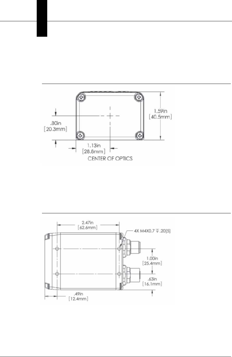
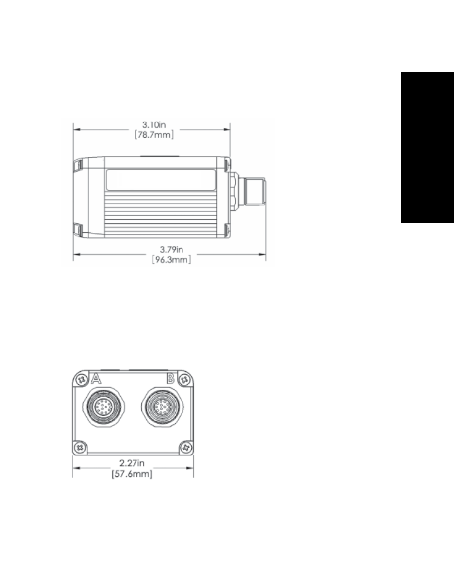
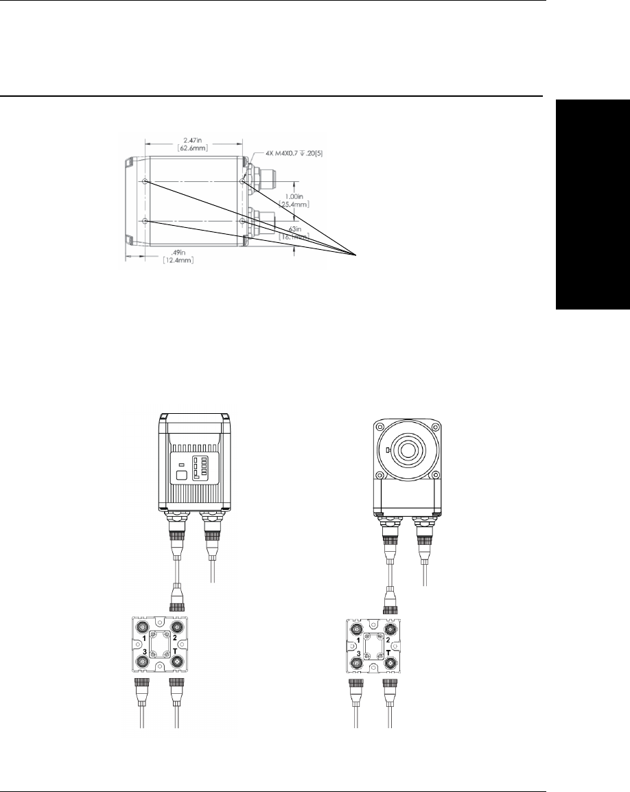
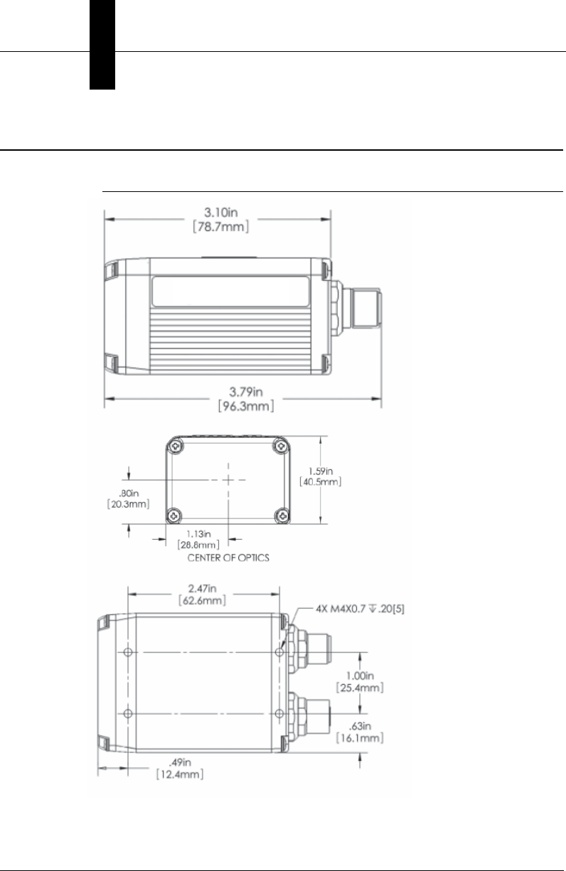
Dimensions
FIGURE C–1. Vision HAWK Smart Camera Dimensions
Note:
Nominal dimensions shown. Typical tolerances apply.
Dimensions
General
Specifications
C
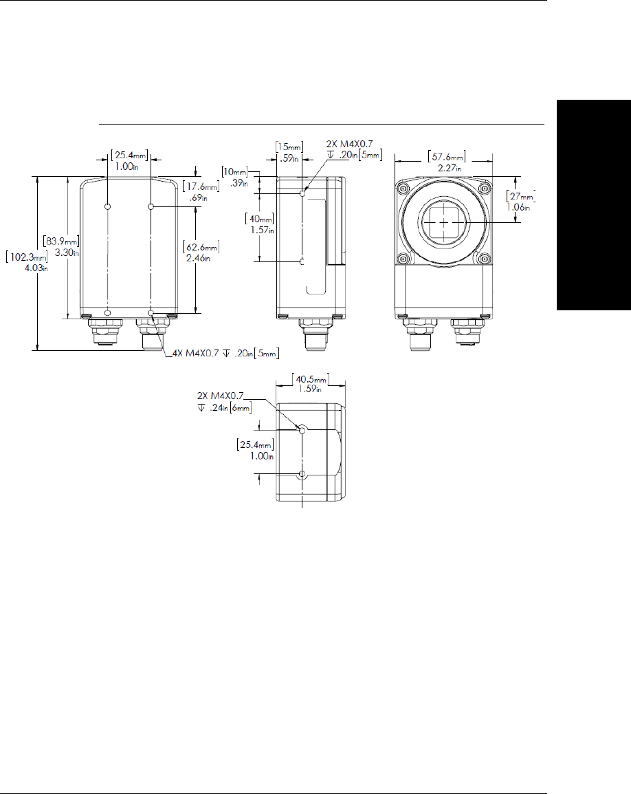
Vision HAWK Smart Camera Guide C-9
FIGURE C–2. Vision HAWK C-Mount Smart Camera Dimensions
Note:
Nominal dimensions shown. Typical tolerances apply.
Appendix CGeneral Specifications
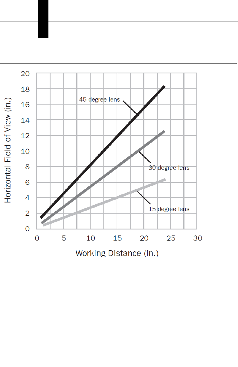
C-10 Vision HAWK Smart Camera Guide
Field of View and Working Distance

Vision HAWK Smart Camera Guide D-1
D
Web HMI
D
APPENDIX D Web HMI
This appendix contains information about Vision HAWK support for
Visualization HMIs.The Vision HAWK features a built in runtime
monitoring web page that can be viewed from any supported browser on
the same network. Supported browsers include:
• Internet Explorer 5.0 or later
• Firefox 3.0 or later
Appendix DWeb HMI
D-2 Vision HAWK Smart Camera Guide
A built-in runtime HTML monitoring page suitable for HMI Panels that
support Internet Explorer 5.0 or later browser such as the SIMATIC M277
Panel is available on the Vision HAWK. Note that the runtime page can
also be displayed with the Firefox or Safari web browsers.
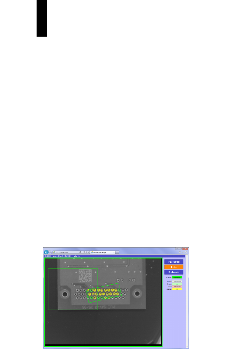
The Runtime Page shows an image from the Vision HAWK, along with
inspection counters and buttons to control certain aspects of the display.
A title bar displays the camera name, ip address and resolution. Options
are available to change if and where the counters, buttons, and titlebar
are displayed. Additionally, up to 10 results values from the job can be
displayed along with each image. These values can either be overlayed
over the image, or shown as a tabular report underneath the image.
All settings and options are set by the user via a series of option pages
which can appear over the main display. All parameters are saved as
cookies in the web browser environment, so that the next time the
Runtime Page is loaded for that device, the layout and settings are
retained.
The Runtime Image Page is accessed via a URL which contains the IP
address of the camera, and optional parameters. The default page is
accessed by simply specifying the IP address of the camera in a web
browser, for example:
http:// 161.218.121.58 (example only, actual IP address of the Vision
HAWK should be used)
If no previous settings have been set by the user, the display will be
similar to the following:
Web HMI
D
Vision HAWK Smart Camera Guide D-3
The default behavior is:
• Images and counters are for the first inspection in the job
• All images (pass & fail) are shown
• The display is automatically refreshed at regular intervals (auto=on)
• Graphics are overlaid on the image (note: not all graphics are
available)
• A border is drawn around the image signifying the status of the
inspection: green=pass, red=fail
The web page includes the following elements:
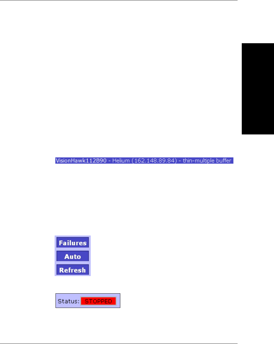
•Title Bar specifying the name of the camera, IP address, and job
(avp) filename. Note that the file extension (.avp) is removed from the
displayed filename.
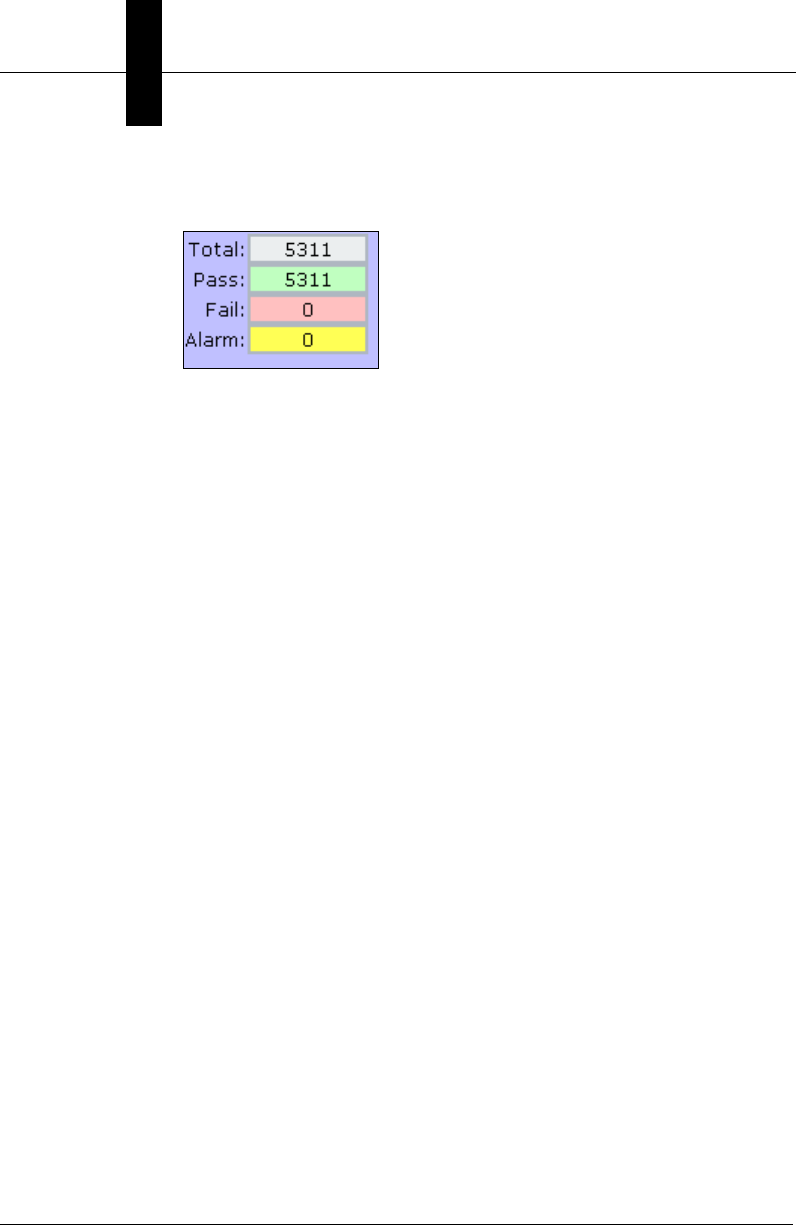
•Failures Push Button – when this button is selected, only images
related to failed inspections are displayed
•Auto Push Button – when this button is selected, the image and
counters are updated automatically. If the button is not selected, both
the image and counters are frozen.
•Refresh Push Button – pushing this button manually updates the
image and counters
•Status – the run status of the inspection – RUNNING or STOPPED
Appendix DWeb HMI
D-4 Vision HAWK Smart Camera Guide
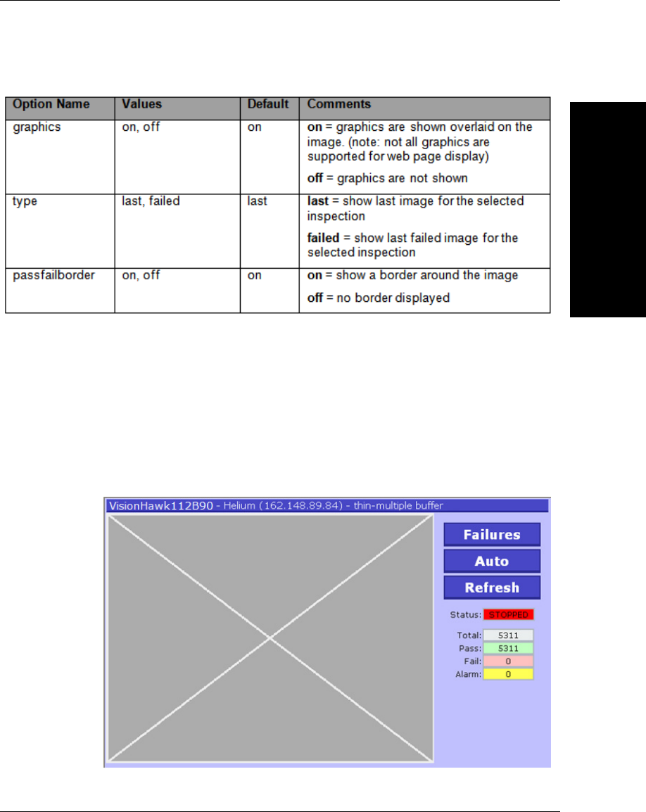
•Counters – the Total, Pass, Fail and Alarm counters are shown for
the selected inspection
Adding Options to the Base URL
An option can be specified by adding it to the end of the URL as follows:
http://ip_address/?option=value
Note the question mark “?” separating the URL from the optional
parameter(s).
Additional options are specified by separating them with the ampersand
“&” character.
http://ip_address/?option1=value1&option2=value2&option3=value3
Basic Options
NOTE: Some basic options can be changed by specifying optional values
at the end of the URL. A much richer superset of these options can be
configured by using the Settings Pages described below. It is possible to
completely control the behavior of the Runtime Page without the use of
optional parameters in the URL.
The graphics overlay can be turned on or off by using the “graphics” URL
option. This is a setting that can have the value “on” or “off”. As an
example, to turn the display of graphics off, the web page can be
launched with the following URL:
http:// 161.218.121.58/?graphics=off
Web HMI
D
Vision HAWK Smart Camera Guide D-5
Note: ROI graphics are not produced by applications created by
AutoVISION. They are displayed for applications created in Visionscape
FrontRunner.
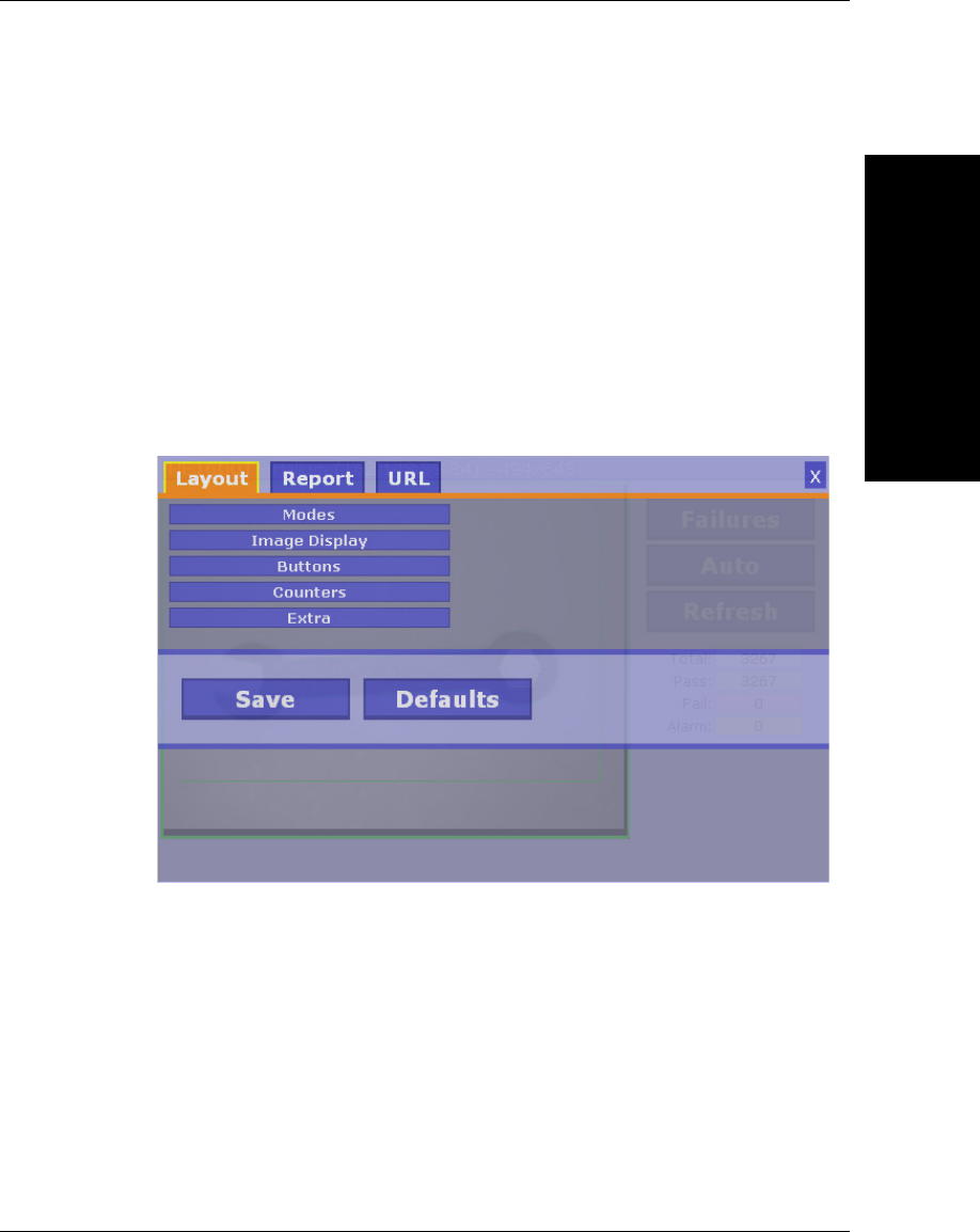
Layout Options
The overall layout of the Runtime Page can be configured. To change the
layout, use the Settings screens as described in the next section. The
following shows a default configuration:
Appendix DWeb HMI
D-6 Vision HAWK Smart Camera Guide
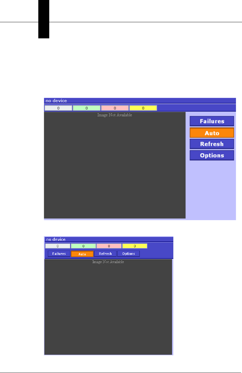
Buttons, status, and counters appear to the right of the image area. The
buttons are size for use via a touch screen.
The following illustrates that the layout has been changed to position the
counters at the top, shown without titles to save room. Additionally, an
Options button now appears in the right side area.
Another example with buttons and counters at the top:
Web HMI
D
Vision HAWK Smart Camera Guide D-7
It is also possible to hide all elements except the image.
Settings Pages
All of the options and settings can be configured by using the settings
pages. By default, there is no “Settings” button, so to show the settings
pages, the URL should be specified with the “setopt=1” parameter as
follows:
http://ip_address/?setopt=1
This will display the Runtime Page overlayed with the Options Setup page
as follows:
The tabs at the top of the screen can be used to navigate between the
several setup pages. To close the setup screens and return to the main
display, use the close button (“X”) at the upper right corner.
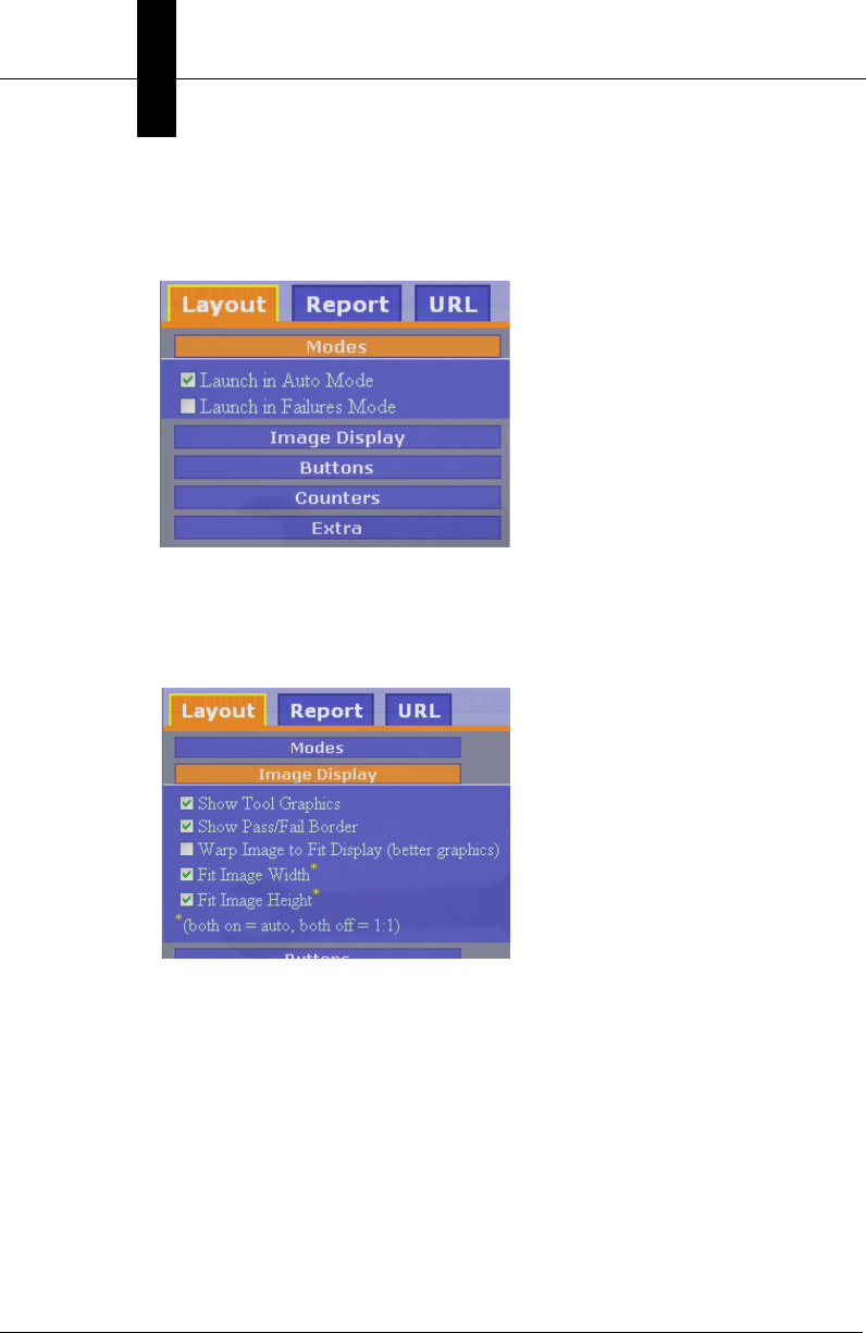
Appendix DWeb HMI
D-8 Vision HAWK Smart Camera Guide
The Layout page controls many layout features, which are organized into
groups. Selecting the Modes group results in the following options being
displayed:
Refer to the table below for a description of the various settings. The
other groups of settings appear as follows:
Image Display:
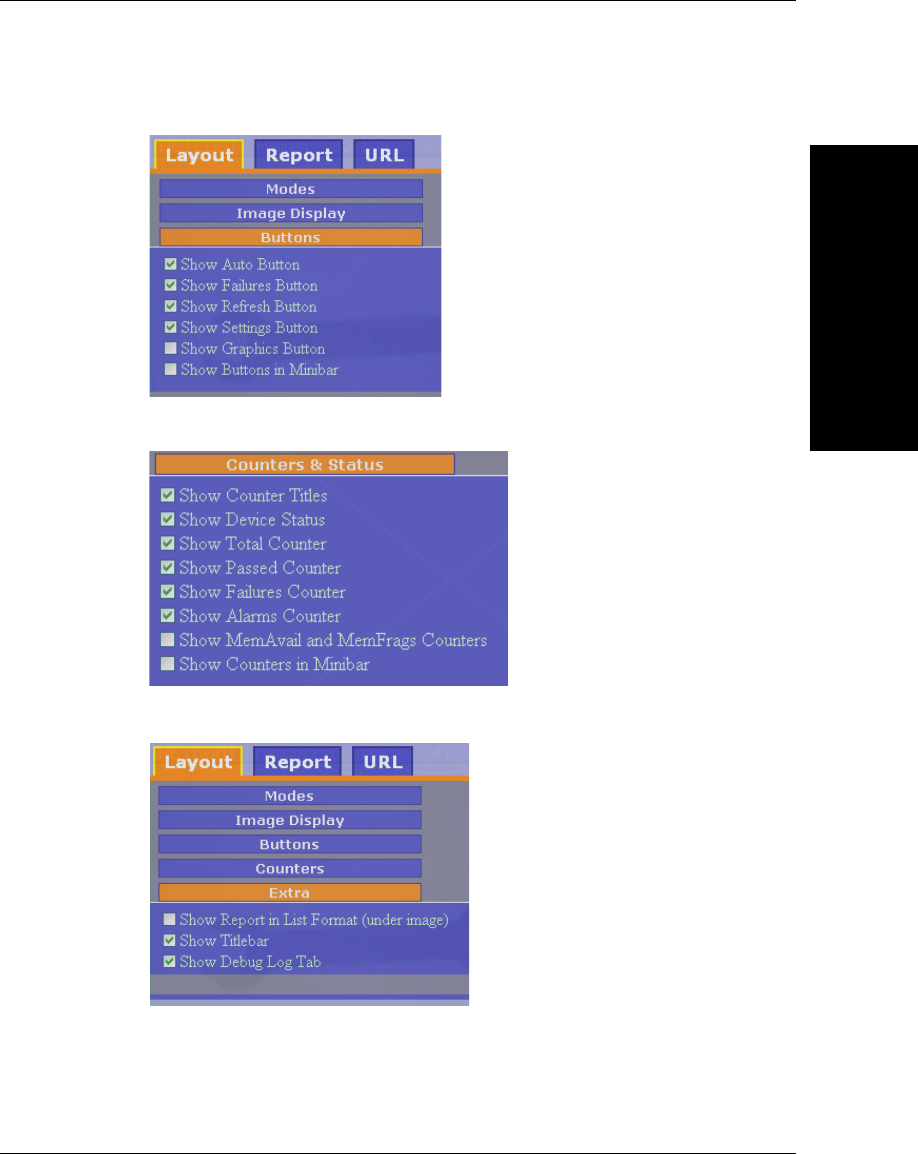
Web HMI
D
Vision HAWK Smart Camera Guide D-9
Buttons:
Counters and Status:
Extra Settings:
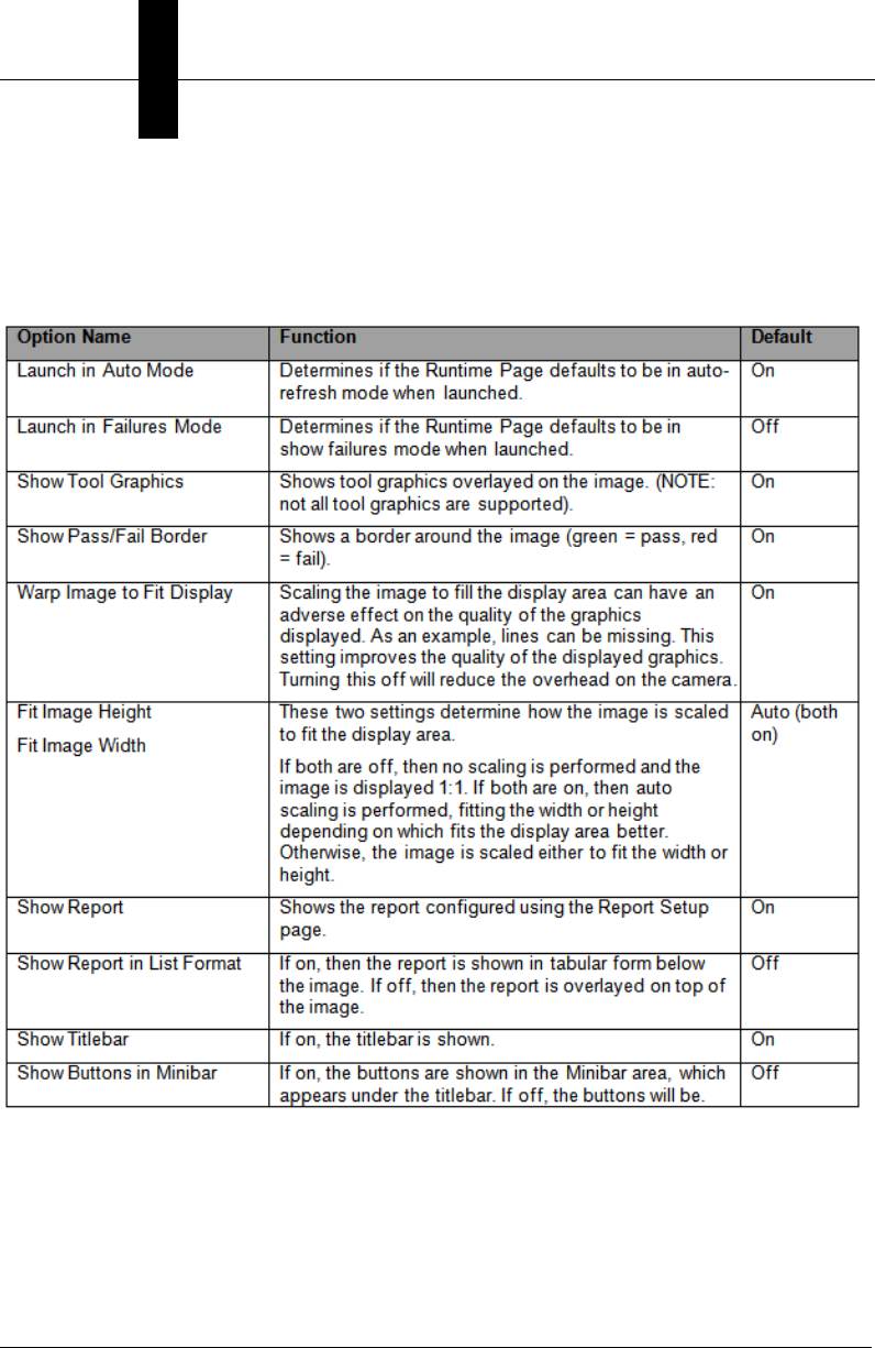
Appendix DWeb HMI
D-10 Vision HAWK Smart Camera Guide
As each option is checked or unchecked, the effect can be seen
immediately by observing the layout of the Runtime Page shown behind
the Options Setup Page.
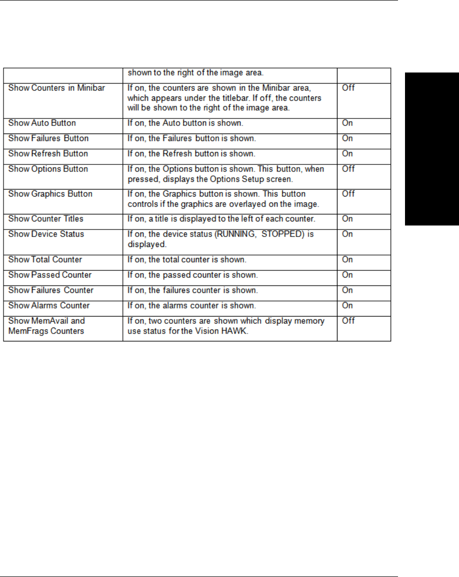
Web HMI
D
Vision HAWK Smart Camera Guide D-11
Pressing the Save button will save these settings so that they become the
default behavior the next time the page is launched.
Pressing the Defaults button will reset the stored settings to the original
defaults the next time the page is launched.
The Close button (“X” in upper right corner) will return to the main
Runtime Page.
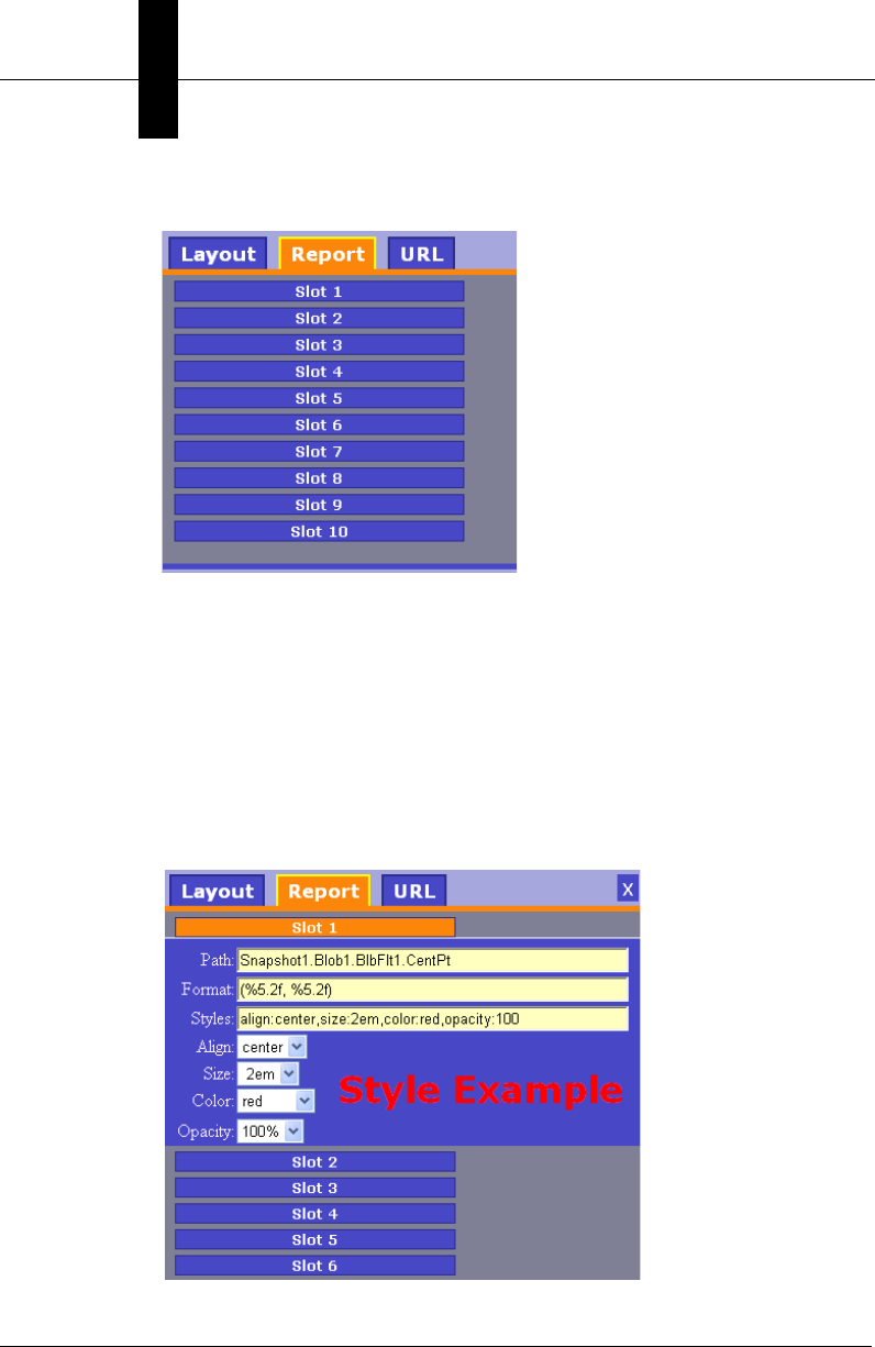
Appendix DWeb HMI
D-12 Vision HAWK Smart Camera Guide
The Report Tab brings up the following Report Setup screen:
Data Values from datums in the selected inspection can be formatted and
overlaid on the displayed image or shown in a table below the image. This
is specified by assigning one of 10 data report slots. If overlayed on the
image, each of these slots will represent a row in the display area, which
is evenly split into 10 equal sized rows. The spacing will depend on the
overall size of the display area, which in turn is dependant on the
dimensions of the browser window. If the report is shown in list form, each
slot corresponds to one of 10 rows.
Selecting a slot to configure results in the following display:

Web HMI
D
Vision HAWK Smart Camera Guide D-13
At a minimum the path to a datum must be specified. The inspection is
implied, so it is not in the path. In the example above, the path
Snapshot1.Blob1.BlbFlt1.CentPt is specified in the first slot.
This would display the value overlaid over the image near the top of the
image display area. If D5 had been used instead, it would appear closer
to the center.
By default, the displayed format will be appropriate for the datum type
requested. However the format can be changed by specifying a printf
style format string.
The format codes must be consistent with the expected data types. If the
result is an integer, then a %d format is expected, floating point numbers
require %f type formats. The list of format codes is not documented here,
refer to printf documentation.
For array values, each element of the array will be passed in turn to the
format string. For example, if a PointDm is being used, there are four
expected array values corresponding to X, Y, angle, scale. (The order is
the same as for variant access via VB). An example of using a format for
PointDm:
(%.2f,%.2f) angle=%.1f scale=%.1f
This will display a result similar to:
(23.23,45.10) angle=3.2 scale=1.0
The later array values can be considered optional and can be omitted if
desired. For example, to display just the x and y values of a PointDm, use
the format string:
center = (%6.2f, %6.2f)
This will display a result similar to:
center = (134.22, 452.12)
If no format string is specified, an appropriate default format is used. For
example, for a LineDm, by default the datum value will be displayed as:
A = value, B = value, C = value
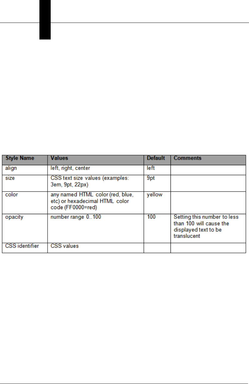
Appendix DWeb HMI
D-14 Vision HAWK Smart Camera Guide
Style
The default display of a report value is left justified, and uses a default
font and color. If desired, all visual aspects of the displayed report value
can be modified. If the Style field is used, it has the format:
style:value,style:value,…
For example, set the text size to 9pt, and align to the right, the following
can be specified:
size:9pt,align:right
Possible style values:
It is permitted to use CSS identifiers to alter other display aspects. For
example, the following will show a red background color for the text:
backgroundColor:red
To set some of the more common styles, the combo boxes for Style, Size,
Color, and Opacity can be used. The styles field will automatically be
updated.
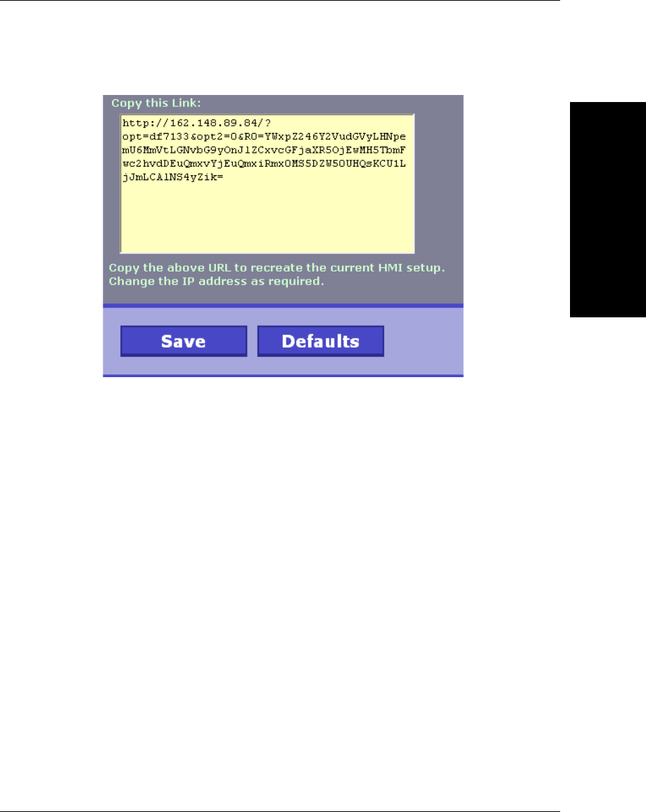
Web HMI
D
Vision HAWK Smart Camera Guide D-15
Selecting the URL tab brings up the following display:
The displayed URL can be copied and then used in a browser window to
completely replicate the current setup.
Additional Notes:
• Line breaks can be inserted into format strings by using embedded
HTML codes. To introduce a line break, use “<br />”
• Commands and options are case sensitive. This is a limitation of
javascript and CSS.
• A new Frontrunner feature allows copying a path of a datum to the
clipboard. Right-click the Datum name in the DatumGrid display, and
select the “Copy path to clipboard” option.

Vision HAWK Smart Camera Guide E-1
E
Allen-Bradley PLC
Setup via EDS
E
APPENDIX E Allen-Bradley PLC Setup
via EDS
This section describes how to set up an Allen-Bradley PLC via EDS file
for use with the Vision HAWK.
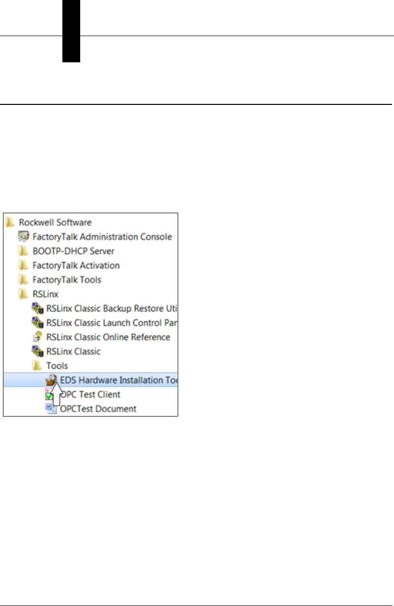
Appendix EAllen-Bradley PLC Setup via EDS
E-2 Vision HAWK Smart Camera Guide
AB Rockwell RSLogix 5000 v20 PLC Integration with EDS
This section was created and run on the following Allen Bradley/Rockwell components:
• RSLogix 5000 Version 20.00.00 (CPR 9 SR 5)
• 756-L61 ControlLogix5561 Controller, firmware rev 20.11
• 1756-ENBT/A EtherNet/IP interface card, firmware rev 4.1
Run the Rockwell “EDS Hardware Installation Tool”.
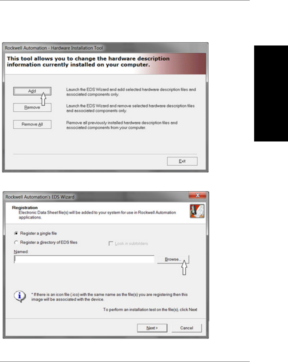
AB Rockwell RSLogix 5000 v20 PLC Integration with EDS
Allen-Bradley PLC
Setup via EDS
E
Vision HAWK Smart Camera Guide E-3
Select Add:
Select Browse:
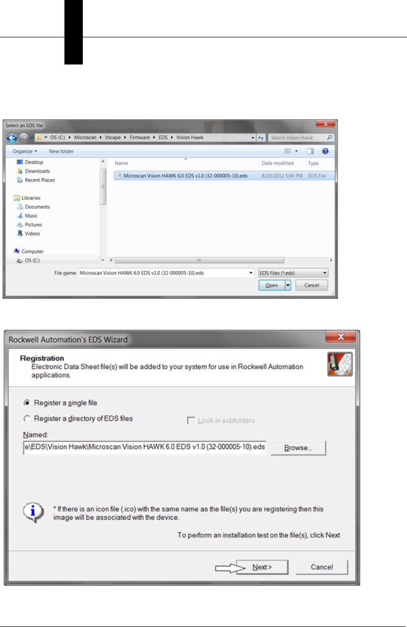
Appendix EAllen-Bradley PLC Setup via EDS
E-4 Vision HAWK Smart Camera Guide
Navigate to the VisionHAWK EDS file, then Open it. The default install location is
C:\Microscan\Vscape\Firmware\EDS\Vision Hawk.
Keep clicking Next > until the Finish button is displayed:
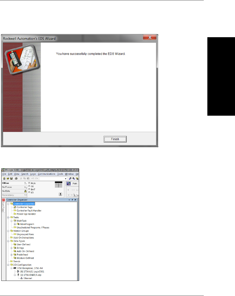
AB Rockwell RSLogix 5000 v20 PLC Integration with EDS
Allen-Bradley PLC
Setup via EDS
E
Vision HAWK Smart Camera Guide E-5
Click Finish:
Open RSLogix 5000 v20 and create the I/O Configuration for the base system, including
the system’s Ethernet interface:
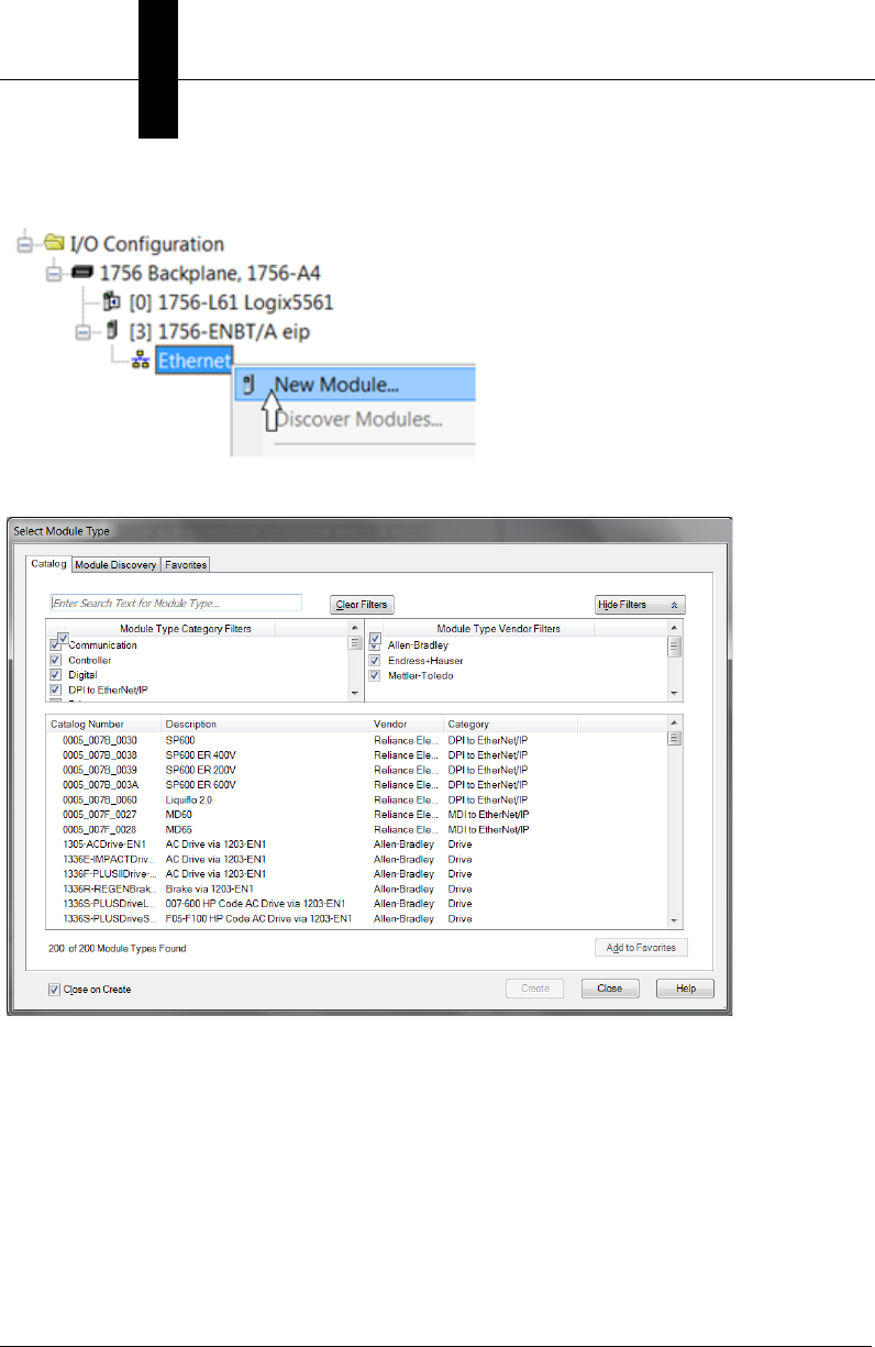
Appendix EAllen-Bradley PLC Setup via EDS
E-6 Vision HAWK Smart Camera Guide
Right click on Ethernet and select New Module:
The Select Module Type dialog is displayed:
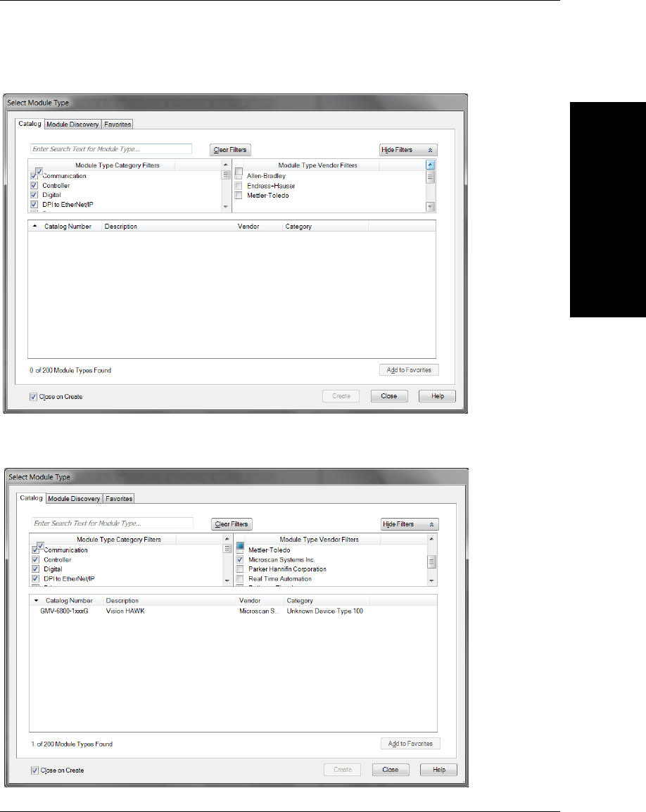
AB Rockwell RSLogix 5000 v20 PLC Integration with EDS
Allen-Bradley PLC
Setup via EDS
E
Vision HAWK Smart Camera Guide E-7
Clear the Module Type Vendor Filters:
Scroll down the Module Type Vendor Filters until Microscan comes into view, then select
Microscan:
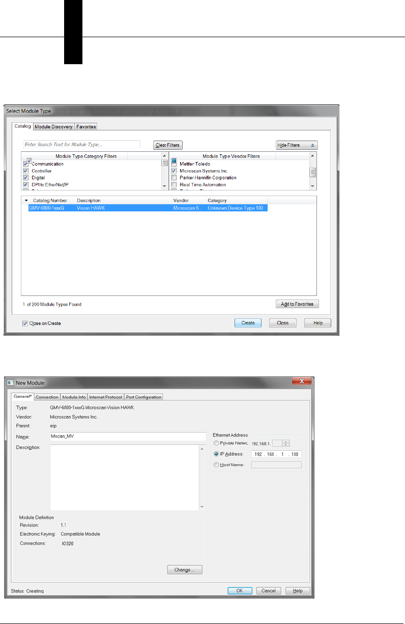
Appendix EAllen-Bradley PLC Setup via EDS
E-8 Vision HAWK Smart Camera Guide
Click the required camera and select Create:
The New Module dialog is displayed. Type a unique name for this camera and its IP
address:
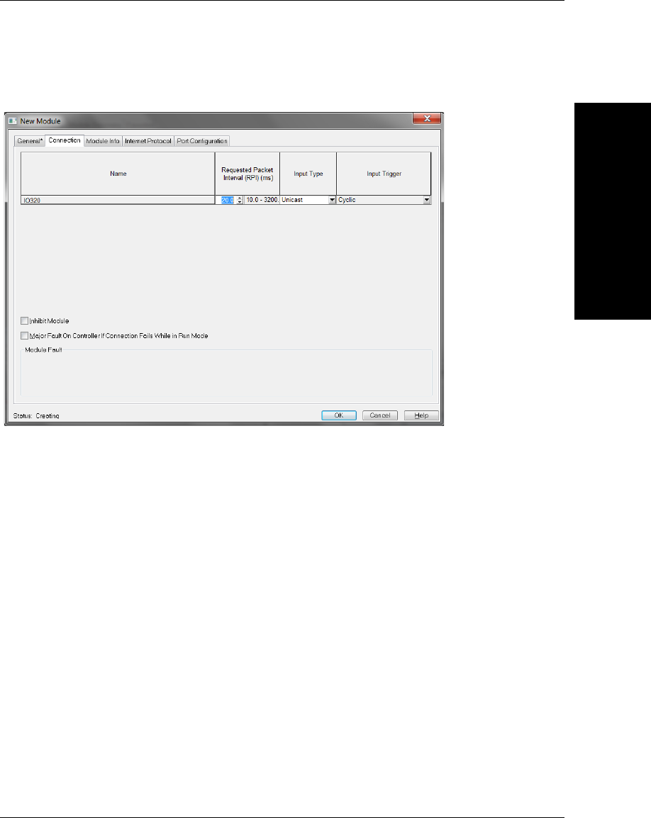
AB Rockwell RSLogix 5000 v20 PLC Integration with EDS
Allen-Bradley PLC
Setup via EDS
E
Vision HAWK Smart Camera Guide E-9
Go to the Connection tab and set the Requested Packet Interval required for the
application:
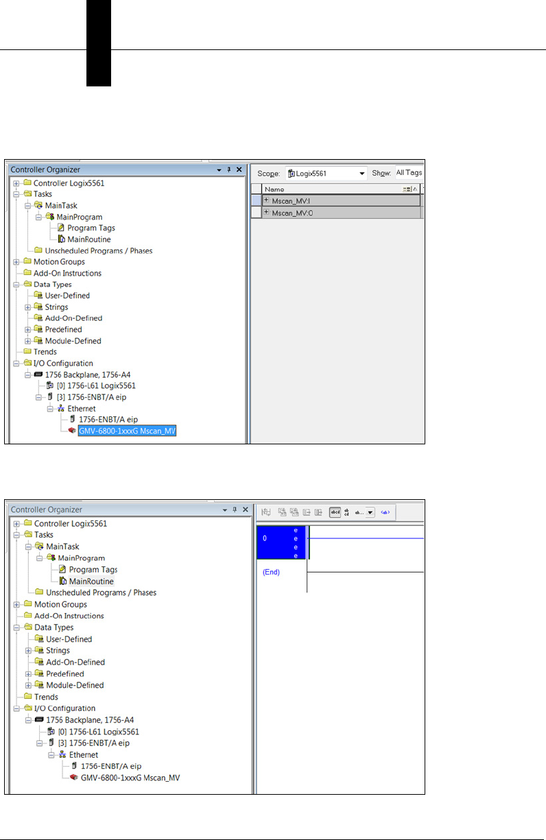
Appendix EAllen-Bradley PLC Setup via EDS
E-10 Vision HAWK Smart Camera Guide
Click OK, verify the camera was added to the Ethernet network, then open the Controller
Tags to verify that :I and :O tag set were created:
Open the Main Routine:

AB Rockwell RSLogix 5000 v20 PLC Integration with EDS
Allen-Bradley PLC
Setup via EDS
E
Vision HAWK Smart Camera Guide E-11
Right click on rung 0, and select Import Rungs:
Navigate to the VisionHAWK 32-000003-lx.L5X file and select Import. The default install
directory is C:\Microscan\Vscape\Tutorials and Samples\Vision Hawk\EIP demo.
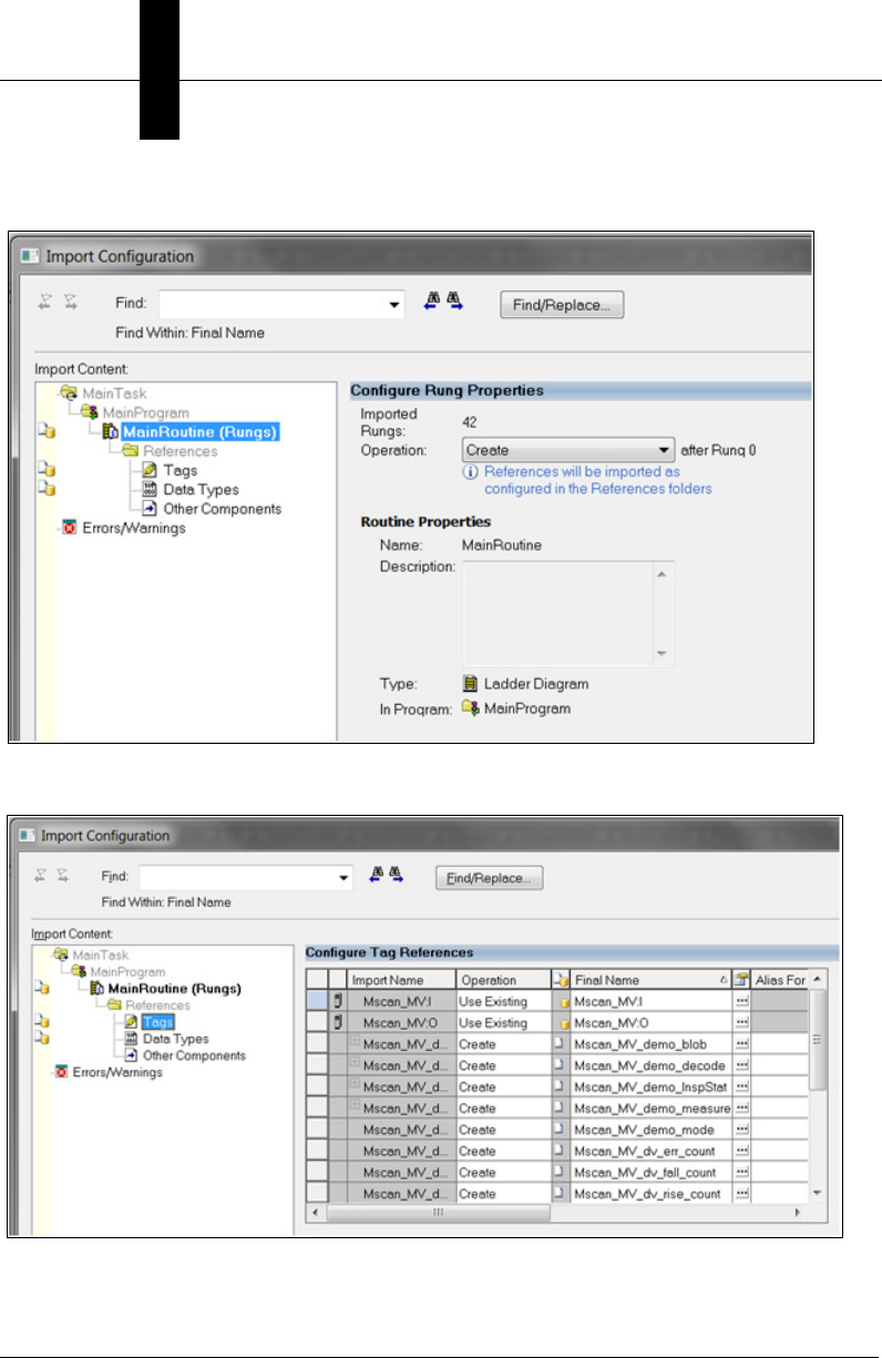
Appendix EAllen-Bradley PLC Setup via EDS
E-12 Vision HAWK Smart Camera Guide
The Import Configuration dialog is displayed:
Select Tags:
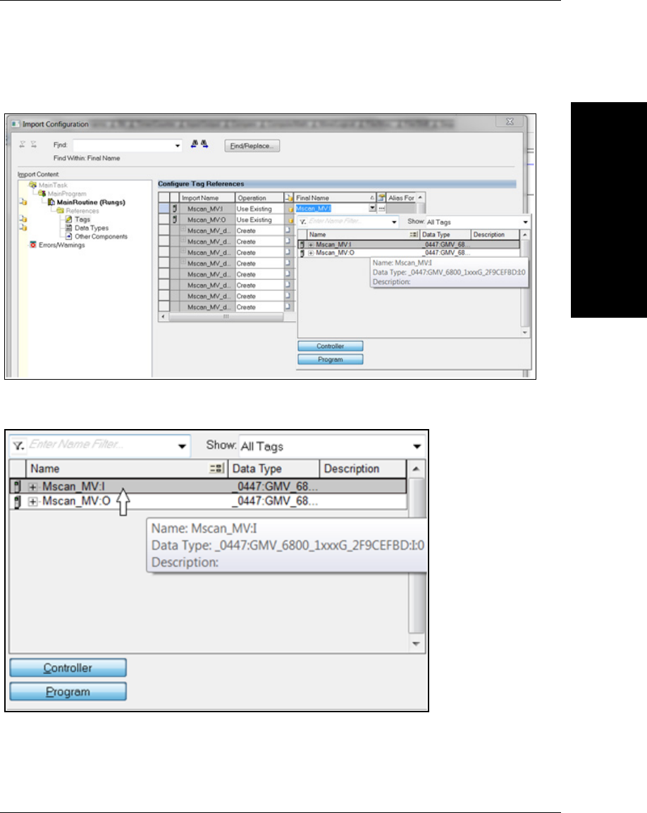
AB Rockwell RSLogix 5000 v20 PLC Integration with EDS
Allen-Bradley PLC
Setup via EDS
E
Vision HAWK Smart Camera Guide E-13
In the Final Name column, click on VisionHAWK:I, then click on the down arrow that
shows up on the right:
Double-click on the Mscan MV:I (or whatever name that was assigned to the device) tag:
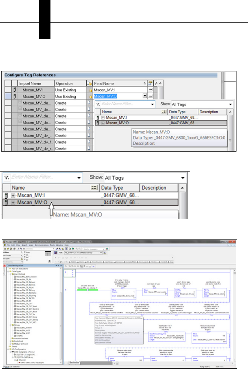
Appendix EAllen-Bradley PLC Setup via EDS
E-14 Vision HAWK Smart Camera Guide
In the “Final Name” column, click on Mscan_MV:O, then click on the down arrow that
shows up on the right:
Double click on the Mscan_MV:O (or whatever name that was assigned to the device) tag:
Click OK and the Main Routine and User Defined tags will be populated:
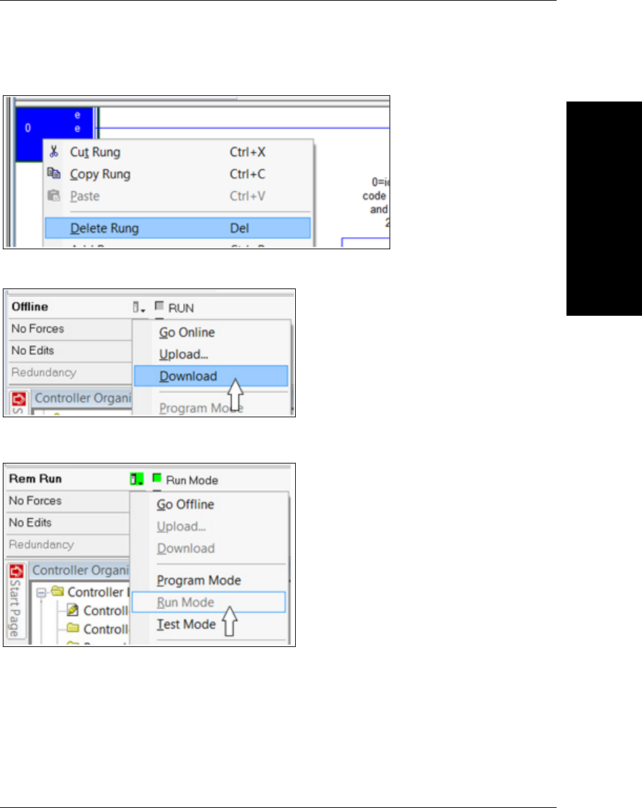
AB Rockwell RSLogix 5000 v20 PLC Integration with EDS
Allen-Bradley PLC
Setup via EDS
E
Vision HAWK Smart Camera Guide E-15
Delete any empty rungs (check rung 0):
Download the project to the PLC:
Put the PLC into Run Mode:
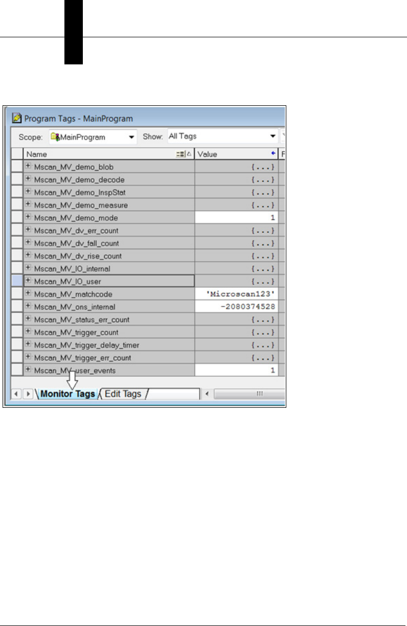
Appendix EAllen-Bradley PLC Setup via EDS
E-16 Vision HAWK Smart Camera Guide
Open the Program Tag window and select “Monitor Tags”:
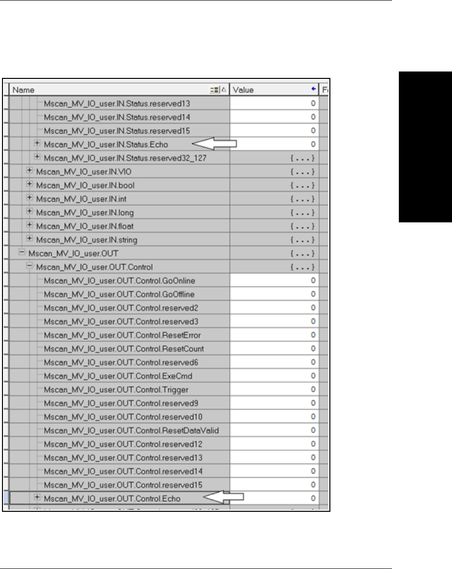
AB Rockwell RSLogix 5000 v20 PLC Integration with EDS
Allen-Bradley PLC
Setup via EDS
E
Vision HAWK Smart Camera Guide E-17
Expand Mscan_MV_IO_user so that the Echo in the .IN.Status and .OUT.Control
structures are visible:
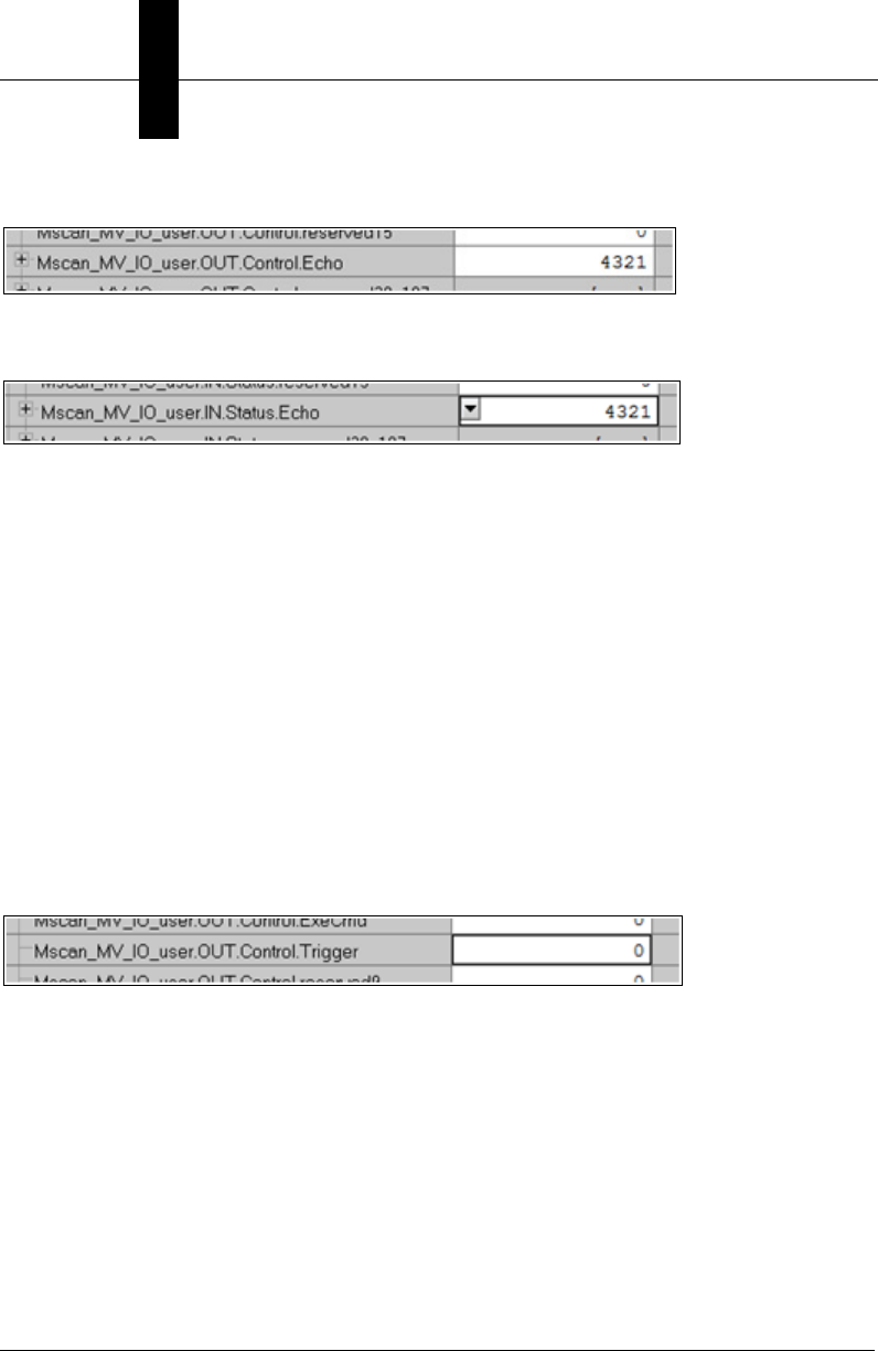
Appendix EAllen-Bradley PLC Setup via EDS
E-18 Vision HAWK Smart Camera Guide
Change .OUT.Control.Echo to non-zero:
Verify Mscan_MV_IO_user.IO.IN.Status.Echo is the same value as the
.OUT.Control.Echo:
This confirms that the PLC and camera have successful two-way communication.
The demo code expects a demo vision job to be loaded on the camera, which populates
the following input tags (camera to PLC) with vision tool results:
• .IN.bool.bool1, bool2, and bool3
• .IN.long.long1
• .IN.float.float1
• .IN.string.string1
The demo code will operate the Control and Status signals of the camera regardless of
whatever vision job is loaded. For a more detailed overview of the demo code and vision
job, please see the associated appendix Demo PLC Code.
To send a trigger to the camera, scroll to Mscan_MV_IO_user.Control.Trigger:
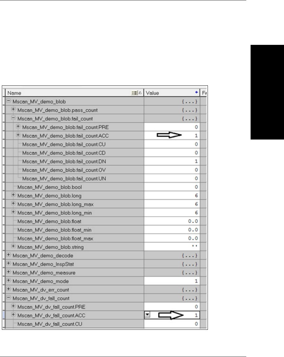
AB Rockwell RSLogix 5000 v20 PLC Integration with EDS
Allen-Bradley PLC
Setup via EDS
E
Vision HAWK Smart Camera Guide E-19
Set the Trigger to 1. This causes the demo code to trigger the camera, process the new
inspection data, record the results in the Mscan_MV_demo_xxxx tags, and clear the
DataValid status signal.
The user of the demo code can know that the camera was triggered when the Trigger
control changes to 0. All processing is done when the counter Mscan_MV_dv_fall_count
increments, along with the pass/fail counters in the Mscan_MV_demo_xxxx tags. For example:

Appendix EAllen-Bradley PLC Setup via EDS
E-20 Vision HAWK Smart Camera Guide

Vision HAWK Smart Camera Guide F-1
F
Allen-Bradley PLC
Setup via Generic
F
APPENDIX F Allen-Bradley PLC Setup
via Generic Ethernet
Module
This section describes how to set up an Allen-Bradley PLC via Generic
Ethernet Module for use with the Vision HAWK.
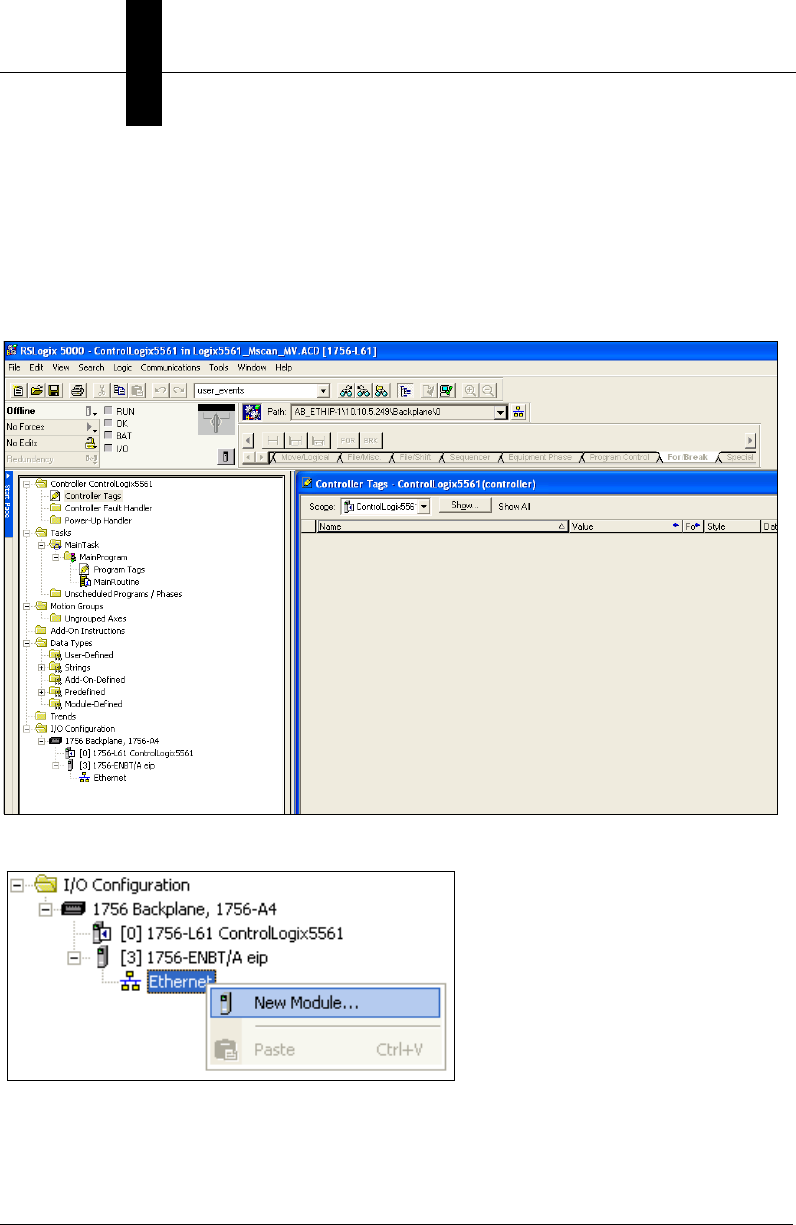
Appendix FAllen-Bradley PLC Setup via Generic Ethernet Module
F-2 Vision HAWK Smart Camera Guide
Prepare the PLC: Integrate the Camera into a PLC Environment
This section assumes you are using an Allen Bradley PLC with Rockwell RSLogix 5000 v16
or newer. RSLogix v19 and v20 may look slightly different than the screen shots shown, but
the integration process is still valid.
Create the I/O Configuration for the base system, including the system’s Ethernet interface:
Add the camera by right-clicking on the Ethernet interface, and select “New Module”:
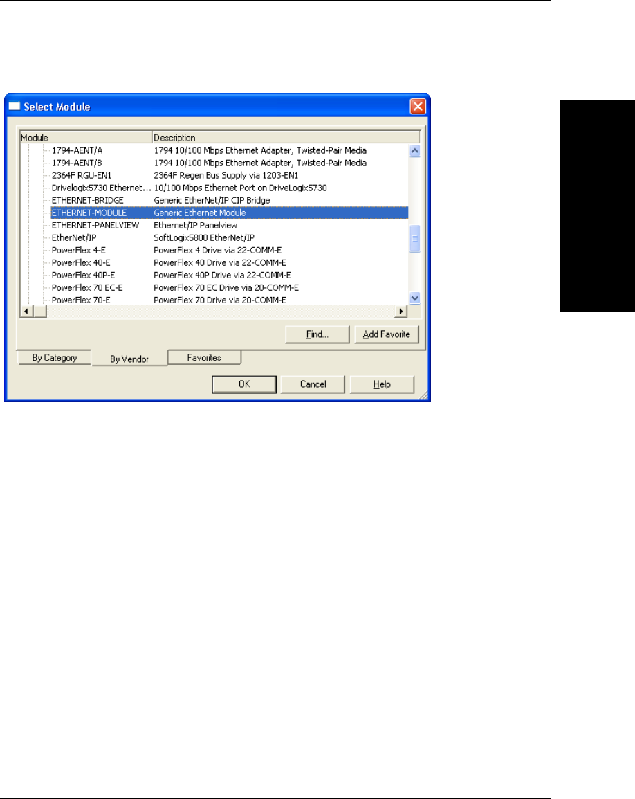
Allen-Bradley PLC
Setup via Generic
F
Vision HAWK Smart Camera Guide F-3
Select “ETHERNET-MODULE Generic Ethernet Module”, and click OK:
Configure the following fields:
“Name” = A useful name to remember the unit. The example here is “Mscan_MV”.
“IP Address” = The IP Address of the camera
“Comm Format” = “Data – DINT”
“Input” “Assembly Instance” = 102
“Input” “Size” = 80
“Output” “Assembly Instance” = 114
“Output” “Size” = 80
“Configuration” “Assembly Instance” = 1
“Configuration” “Size” = 0 (none)
Click OK when done.
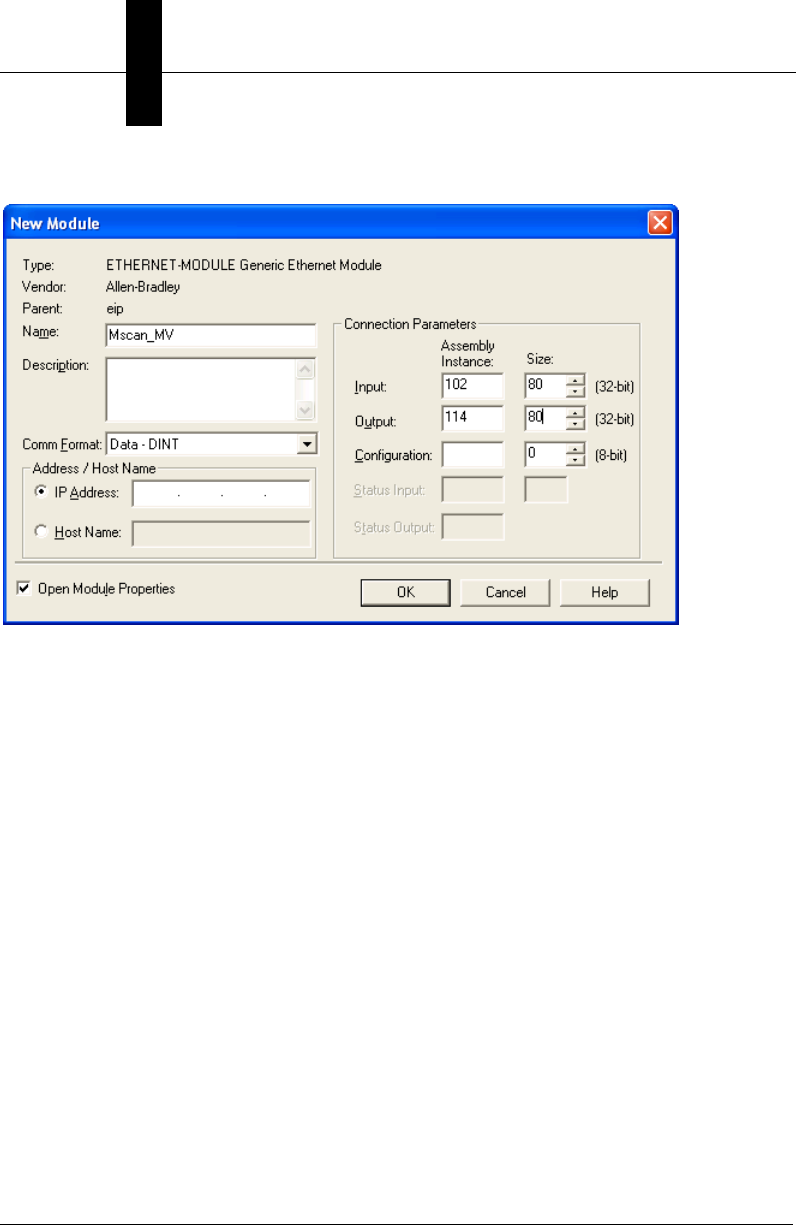
Appendix FAllen-Bradley PLC Setup via Generic Ethernet Module
F-4 Vision HAWK Smart Camera Guide
Example:
Configure the “Required Packet Interval (RPI)” and click OK.
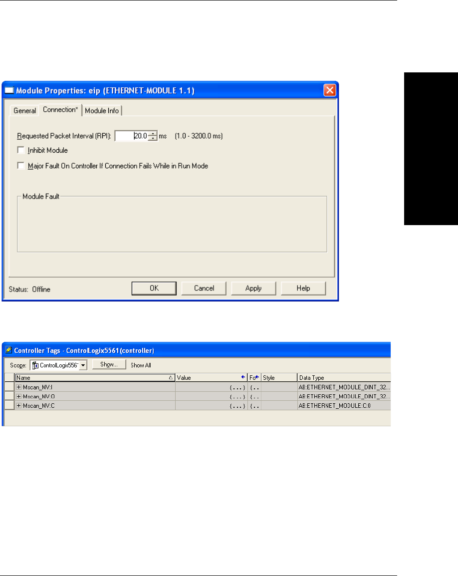
Allen-Bradley PLC
Setup via Generic
F
Vision HAWK Smart Camera Guide F-5
10 ms is the minimum allowed by the camera, 20 ms or higher is recommend, as required
by the application:
Double-click on the “Controller Tags” item, and verify VH’s :I and :O tags appear in the
Controller Tags window:

Appendix FAllen-Bradley PLC Setup via Generic Ethernet Module
F-6 Vision HAWK Smart Camera Guide
Open the “Main Routine”:
Right-click on the top rung and select “Import Rung”:
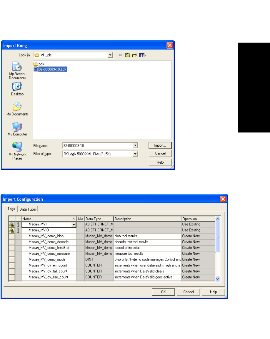
Allen-Bradley PLC
Setup via Generic
F
Vision HAWK Smart Camera Guide F-7
Navigate to the “32-000003-lx.L5X” file and click “Import”:
At the “Import Configuration” window, find the Module Name that was assigned to the
Generic Module. Here the module name is “Mscan_MV”:

Appendix FAllen-Bradley PLC Setup via Generic Ethernet Module
F-8 Vision HAWK Smart Camera Guide
Click on Mscan_MV:I, then click on the down-arrow, then double click on the
“Mscan_MV:I” that appears below it:
Note the “*” that appears on the far left of the dialog box for the Mscan_MV:I line:
Click on Mscan_MV:O, then click on the down-arrow, then double click on the
“Mscan_MV:O” that appears below it:

Allen-Bradley PLC
Setup via Generic
F
Vision HAWK Smart Camera Guide F-9
Note the “*” that appears on the far left of the dialog box for the Mscan_MV:O line:
Click OK.
Delete any empty rungs (rung 0 may be empty):
The tags and main program are now configured sufficiently to test communication with the
camera.
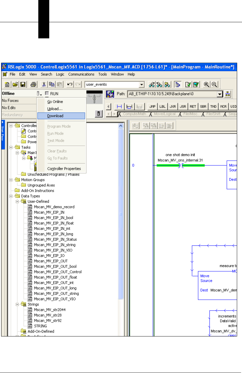
Appendix FAllen-Bradley PLC Setup via Generic Ethernet Module
F-10 Vision HAWK Smart Camera Guide
Select the control button next to “Offline”, and select “Download”:
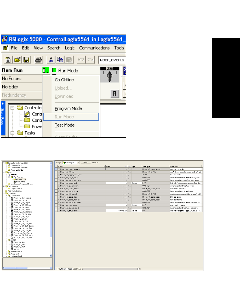
Allen-Bradley PLC
Setup via Generic
F
Vision HAWK Smart Camera Guide F-11
Once the program has downloaded, make sure the PLC is in Run Mode:
To open the Program Tags, double-click on “Program Tags”, then select the “Monitor Tags”
tab at the bottom of the tag window:
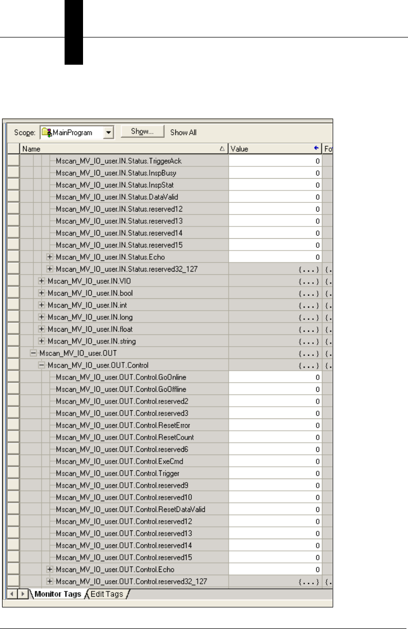
Appendix FAllen-Bradley PLC Setup via Generic Ethernet Module
F-12 Vision HAWK Smart Camera Guide
Expand Mscan_MV_IO_user so that the .IN.Status and .OUT.Control structures are
visible, then scroll the window so Mscan_MV_IO_user.OUT.Control.Echo is visible:
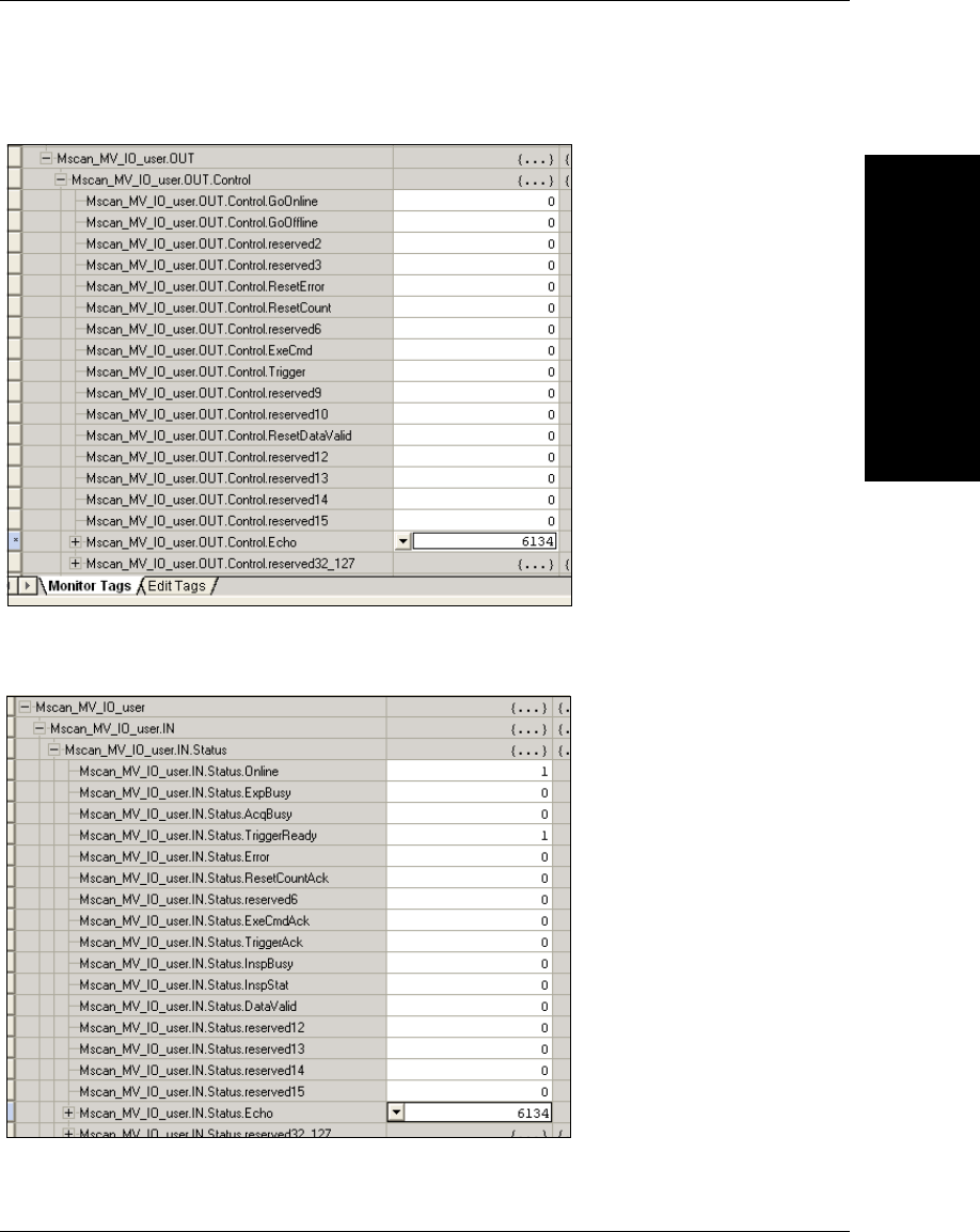
Allen-Bradley PLC
Setup via Generic
F
Vision HAWK Smart Camera Guide F-13
Change .OUT.Control.Echo to non-zero:
Scroll the window so Mscan_MV_IO_user.IO.IN.Status.Echo is visible, and verify it is the
same value as the .OUT.Control.Echo:
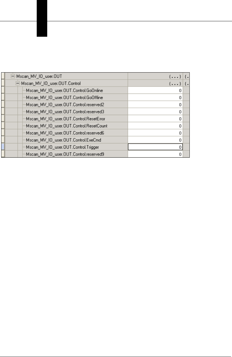
Appendix FAllen-Bradley PLC Setup via Generic Ethernet Module
F-14 Vision HAWK Smart Camera Guide
This confirms that the PLC and camera have successful two-way communication.
To send a trigger to the camera, scroll to Mscan_MV_IO_user.Control.Trigger:
Set the Trigger to 1. This causes the demo code to trigger the camera, process the new
inspection data, record the results in the Mscan_MV_demo_xxxx tags, and clear the
DataValid status signal. The user can know that the camera was triggered when the
Trigger control changes to 0. The user can know that all processing is done when the
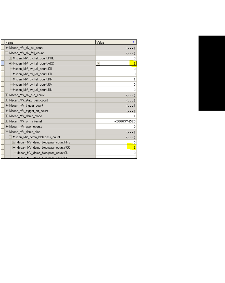
Allen-Bradley PLC
Setup via Generic
F
Vision HAWK Smart Camera Guide F-15
counter Mscan_MV_dv_fall_count increments, along with the pass/fail counters in the
Mscan_MV_demo_xxxx tags. For example:
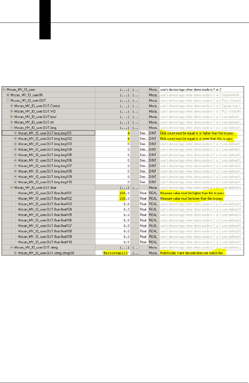
Appendix FAllen-Bradley PLC Setup via Generic Ethernet Module
F-16 Vision HAWK Smart Camera Guide
Parameterize the Camera
Open the Mscan_MV_IO_user.OUT.long, float, and string tags and verify they are
configured as follows:
This configures the Measure (float101 and float102), Decode (string101) and Count Blob
(long101 and long102) tools in the same way they were configured in AutoVISION during
Try Out.
Note the Description column. It offers a hint for what each linked tag does for the vision job.
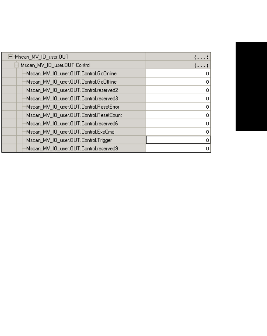
Allen-Bradley PLC
Setup via Generic
F
Vision HAWK Smart Camera Guide F-17
Trigger the Camera
To send a trigger to the camera, scroll to Mscan_MV_IO_user.Control.Trigger:
Set the Trigger to 1. When the Trigger returns to a value of 0, the camera may be
retriggered.
If you connect to the camera with AutoVISION, it will display a new Inspection result each
time the camera is triggered. Recall that the vision job was created with pre-defined
images to produce predictable “Passed” and “Failed” results. The camera’s illumination
lights will not flash when triggered.
The Inspection results can be seen in the PLCs’s IN tags, and well as in AutoVISION.
Open the RSLogix tag window so Mscan_MV_IO_user.IN.Status and bool are visible.
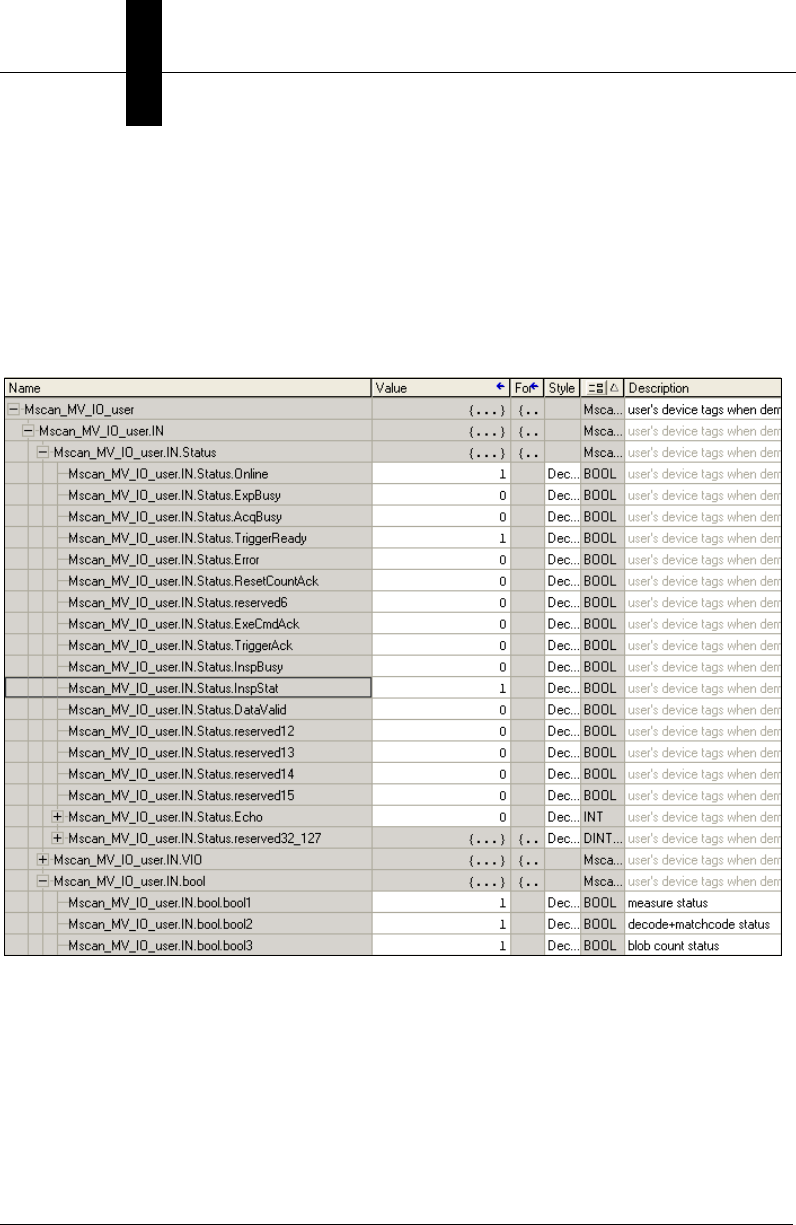
Appendix FAllen-Bradley PLC Setup via Generic Ethernet Module
F-18 Vision HAWK Smart Camera Guide
This example shows a “Passed” inspection, where the following tags are all 1:
IN.Status.InspStat
IN.bool.bool1 (Measure status)
IN.bool.bool2 (decode+matchcode status)
IN.bool.bool3 (count blob status)

Allen-Bradley PLC
Setup via Generic
F
Vision HAWK Smart Camera Guide F-19
If you scroll down to the IN.long, float and string values, you will see the literal results of
the vision tools:

Appendix FAllen-Bradley PLC Setup via Generic Ethernet Module
F-20 Vision HAWK Smart Camera Guide
This is equivalent to the AutoVISION inspection result:
This example shows a “Failed” inspection, where every tool reports a fail:
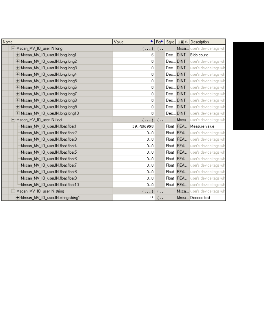
Allen-Bradley PLC
Setup via Generic
F
Vision HAWK Smart Camera Guide F-21
This is the Failed inspection’s literal data:
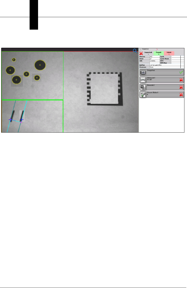
Appendix FAllen-Bradley PLC Setup via Generic Ethernet Module
F-22 Vision HAWK Smart Camera Guide
This is equivalent to the AutoVISION inspection report:
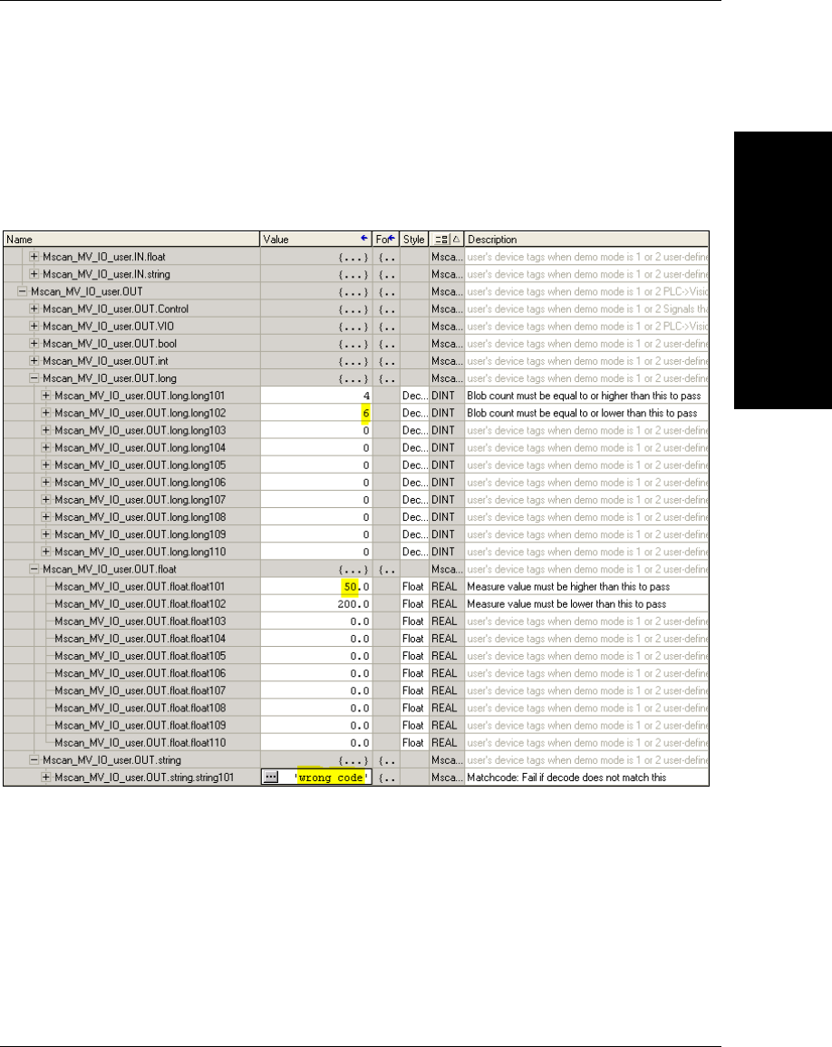
Allen-Bradley PLC
Setup via Generic
F
Vision HAWK Smart Camera Guide F-23
Parameterize the Camera Again
The Measure and Count Blob tools can be parameterized by the PLC so they always
pass. The Decode tool can be parameterized so it always fails, either due to no decode, or
a matchcode mismatch. Scroll the tag window so OUT.long, float and string are visible,
then change them as shown here:
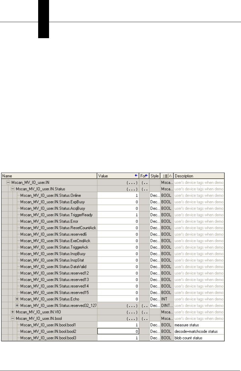
Appendix FAllen-Bradley PLC Setup via Generic Ethernet Module
F-24 Vision HAWK Smart Camera Guide
Trigger the Camera Again
Trigger the camera twice, and you will see the Status results stay the same for all triggers:
bool2 (decode+matchcode status) = 0
Why: Decode+Matchcode status always fails because the matchcode has been changed
to “wrong code”, or there is no decode.
bool1 (Measure status) and bool3 (count blob status) = 1
Why: The inspected values are now in tolerance.
InspStat = 0
Why: The Decode tool fails, so the overall Inspection result is a Fail.
PLC tags:
This concludes the EtherNet/IP demo.

Vision HAWK Smart Camera Guide G-1
G
Demo PLC Code
G
APPENDIX G Demo PLC Code
This section describes how to use Microscan demo PLC code with a
vision job and camera target.
The EIP demo files can be found where AutoVISION is installed, in the
folder C:\Microscan\Vscape\Tutorials and Samples\Vision Hawk\EIP demo.
Open the EIP_demo.avp with AutoVISION and download it to the camera.
During PLC integration, import the 32-000003-lx.L5X file to create the
camera’s demo tags and ladder logic.

Appendix GDemo PLC Code
G-2 Vision HAWK Smart Camera Guide
Glossary of Terms
The following terms are used in the description of Microscan’s demo PLC
program.
Camera
The Microscan Smart Camera used in this application, which has an
EtherNet/IP communication interface.
User App
The PLC logic code written by the end user or system integrator.
Demo Code
The PLC logic code distributed by Microscan that can be imported into the
PLC’s ladder logic area. It encapsulates most of the device Control and
Status management.
The demo code expects a demo vision job loaded on the camera.
However, the demo code will operate whether or not the demo vision job
is loaded on the camera.
Activate / Set High
Writing a 1 value to a single Control bit, or any other bool bit.
Active
A Control, Status, bool, or PLC logic “contact” in a 1 state.
Clear
A Control, Status, bool, or PLC logic “contact” in a 0 state.
One Shot
PLC tag write operation that is performed once, typically in reaction to an
event. After a one shot operation, the PLC logic does not write to the
same tag again unless another event occurs.
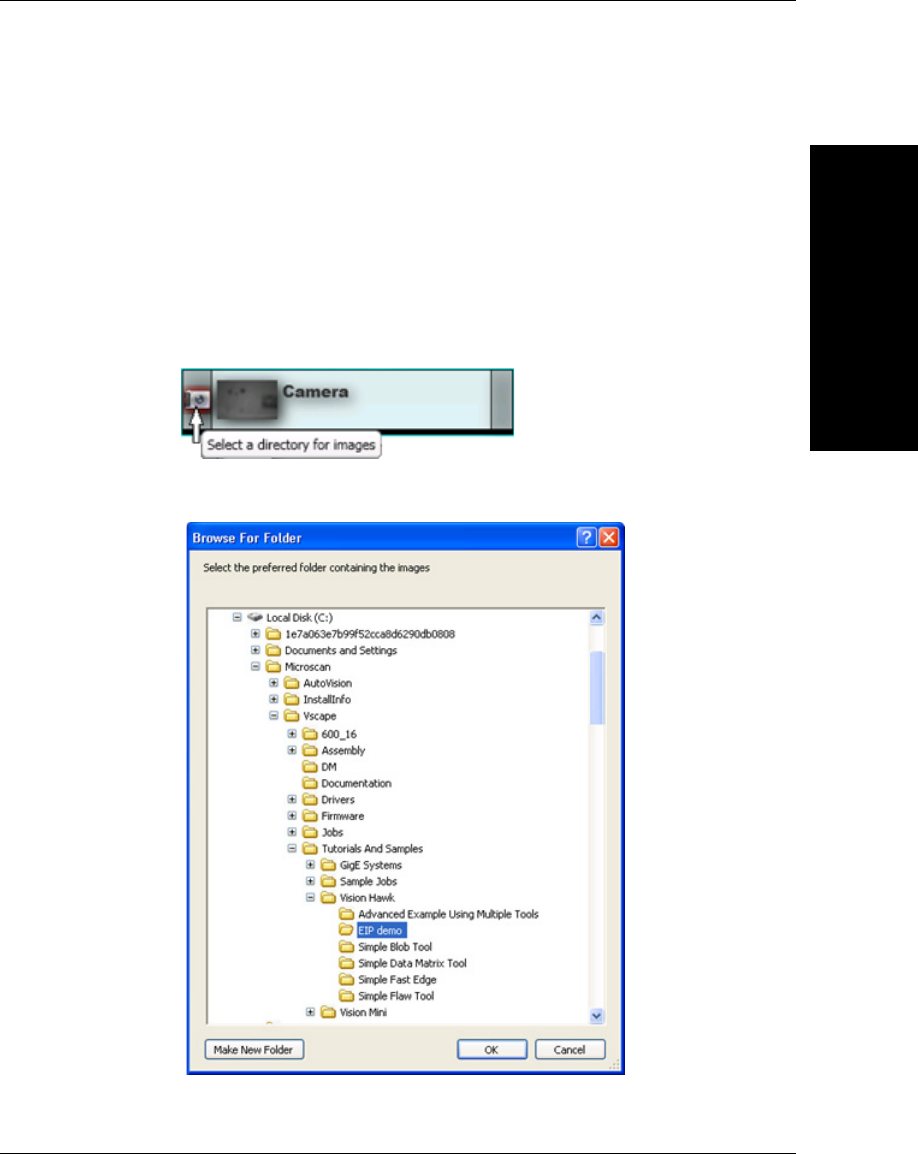
Demo PLC Code
G
Vision HAWK Smart Camera Guide G-3
Demo Setup
Vision Job Setup
The EIP demo files can be found where AutoVISION is installed, where
the default folder is C:\Microscan\Vscape\Tutorials and Samples\Vision
Hawk\EIP demo.
1. Open EIP_demo.avp with AutoVISION.
2. To use pre-defined images, select the camera icon on the Camera tool.
3. Browse to the EIP demo folder, select it, and click OK.
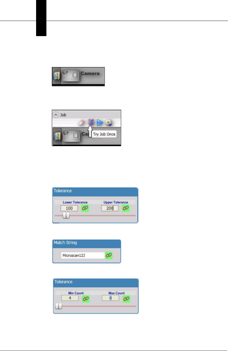
Appendix GDemo PLC Code
G-4 Vision HAWK Smart Camera Guide
After the EIP demo folder has been enabled for image load, the
camera icon will change to a folder:
4. While in Edit mode, Try Out can be used to get an understanding of
what to expect after the job is sent to the camera.
Before Try Out can be effective, the Measure, Decode, and Count
Tool parameters must be specified. After job download, the tool
parameters will be supplied by the PLC.
Measure Tolerance:
Decode Matchstring:
Count Tolerance:
With these tool parameter configured as shown, Try Out will show the
following Pass/Fail results.
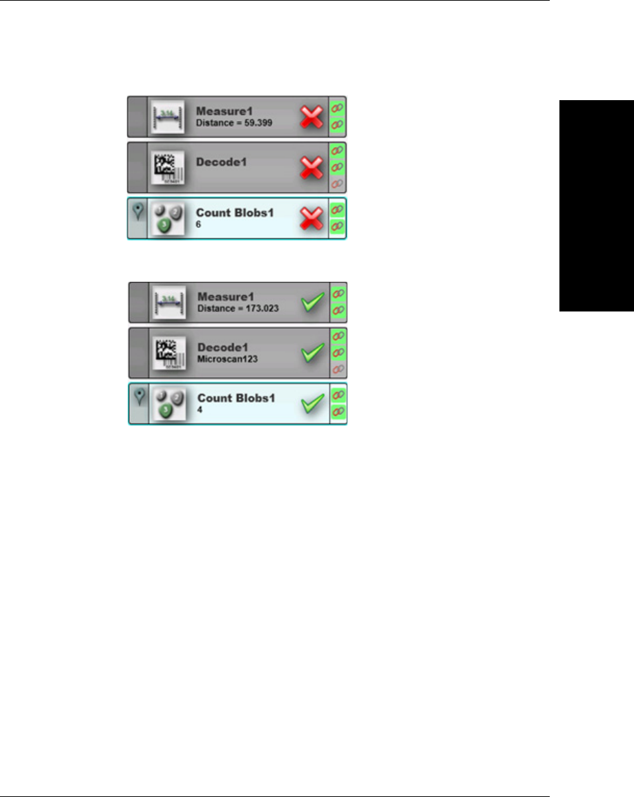
Demo PLC Code
G
Vision HAWK Smart Camera Guide G-5
Fail:
Pass:
5. Download the job to the camera.
6. Add the camera and demo code to the PLC environment (see the
next section).
PLC Demo Code Setup
During PLC integration, import the 32-000003-lx.L5X file, found in the EIP
demo folder, to create the camera’s demo tags and ladder logic. Please
refer to Allen-Bradley PLC Setup via EDS.
Description of PLC Tags
Mscan_MV_demo_mode
Purpose
This is intended for demonstration purposes only, to modify the operation
of the demo code. It allows the first-time user to control the device directly

Appendix GDemo PLC Code
G-6 Vision HAWK Smart Camera Guide
with no assistance from the demo code, or allow the demo code to
manage the Control and Status signals fully.
The demo mode tag takes three different values, putting the demo code
into one of three modes of operation:
• Exchange IO data only
• Actively operate device controls, status, and demo data
• Automatically trigger the device after one second of idle time
User App Method
User app can set the demo mode with one of three values to define the
demo code’s mode of operation.
0=Exchange IO data only
In this mode, the user directly accesses the Mscan_MV_IO_internal tag
set. The demo code only exchanges data with the camera, doing nothing
to control the device or respond to events from it.
1=Operate device controls and respond to device events
This is the default mode of the demo code. In this mode, the user app
accesses the Mscan_MV_IO_user tag to control and monitor the camera.
The user app must not access the Mscan_MV_IO_internal tag set.
In this mode, the user activates the controls in
Mscan_MV_IO_user.OUT.Control (Trigger, ResetCount, GoOnline,
GoOffline, ResetError, ExeCmd), and the demo code handles the rest.
2=Auto-trigger
In this mode, the demo code fully manages the Control and Status
signals, the same as when the mode is set to 1. It also activates the
camera’s trigger after one second of idle time. The timer used to drive the
trigger is Mscan_MV_trigger_delay_timer.
Demo Code Usage
Depending on the mode, the demo code will run the appropriate level of code.
• In mode 0, only the IO exchange rungs are executed. All others are
bypassed (ladder jmp).

Demo PLC Code
G
Vision HAWK Smart Camera Guide G-7
• In mode 1, the auto-trigger rungs are bypassed. This is the default
mode of the demo code.
• In mode 2, all rungs are executed.
Mscan_MV_IO_user
Purpose
User-accessible IO data for the camera. The user app reads and writes
these IO tags, and the demo code handles the actual on-the-wire control
of the camera.
User App Method
Activate a Control by setting its value to 1.
The user app can determine that the Control is done when the Control is
clear (demo code changes the Control to a bit/bool value of 0). Do not
attempt to activate a Control unless it is clear.
The user app should activate the Controls using one-shot writes. The use
app should not continuously hold a Control in an active state. Holding a
Control in an active state will prevent the demo code from notifying the
user app that the Control operation is complete by clearing the Control.
Usually, when a Control is clear (0), the camera is ready for the Control to
be activated again. Please see the Specific Control Guidelines and
Specific Status Guidelines below for qualifications.
Demo Code Usage
The demo code waits for the user app to activate a Control. When the
user app activates a Control, the demo code handles all handshaking and
confirmation that the Control operation is performed by the camera. When
the operation is complete, the demo code clears the Control back to 0.
Specific Control Guidelines
GoOnline and GoOffline
In order to take the camera Online and Offline, only one of these Controls
can go active (change from 0 to 1), and be active, at any given time.

Appendix GDemo PLC Code
G-8 Vision HAWK Smart Camera Guide
ResetCount
After the user app activates ResetCount, the demo code will clear
ResetCount when the operation is complete. The next Inspection output
will be #1 (as can be seen if AutoVISION is connected to the camera in
run mode).
Trigger
Do not trigger the camera unless the TriggerReady Status is active. If the
Trigger goes active when TriggerReady is not active, the demo code
increments the counter Mscan_MV_trigger_err_count, and immediately
clears the Trigger Control, without attempting to trigger the camera.
After the user app activates the Trigger, the demo code will clear the
Trigger when the camera indicates it has accepted the Trigger.
Do not re-trigger the camera until DataValid in the Status register goes
active, all Inspection data has been processed, and the DataValid is
cleared using the ResetDataValid Control.
ResetDataValid
When the user app sees DataValid go active, it should process the
Inspection data, then clear DataValid by activating ResetDataValid.
See Data Valid for more details.
ResetError
To clear the Error Status, activate ResetError.
ExeCmd, CmdCode, CmdArg
These Controls can be used to perform a job change, and query the
active job slot. Refer to the CmdCode section of the EIP chapter for
available command codes, command result codes, and a diagram of
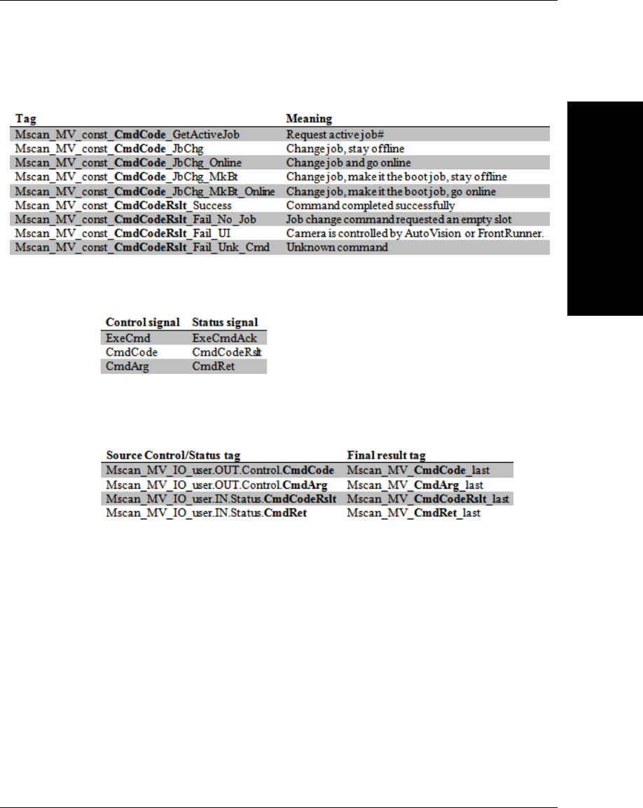
Demo PLC Code
G
Vision HAWK Smart Camera Guide G-9
command execution. The demo code includes tags with pre-defined
CmdCode and CmdCodeRslt definitions:
The ExeCmd, CmdCode, and CmdArg controls are used in combination
with these Status signals:
The demo code records the final result of the command operation by
copying CmdCode, CmdArg, CmdCodeRslt and CmdRet to the
following tags:
The demo code will automate the command process when
Mscan_MV_demo_mode is 1, which is the default value at program
startup, similar to how it assists the Triggering and DataValid Controls.
The PLC integrator can initiate command operation by accessing the
demo code’s Mscan_MV_IO_user tag set for Control and Status signals.
While a command operation is active, the demo code forces all Control
signals to an inactive state, except for the Echo. No Controls can be
activated until the command operation is completed. To verify the camera
is still “alive” during command execution, the Control.Echo can be
incremented, and the Status.Echo will update accordingly.
When the demo code automates the command process, the PLC
integrator is responsible for the following steps:

Appendix GDemo PLC Code
G-10 Vision HAWK Smart Camera Guide
1. Deactivate all Controls and clear DataValid and Error status signals.
This is a “best practice” measure, to ensure that the PLC has
transitioned from a state of triggering and processing inspections, to
issuing a command.
2. If a job change command is to be issued, populate the output tags
required to configure the new job (bool, int, long, float, string).
3. Write the required CmdCode (see
Mscan_MV_const_CmdCode_xxxx tags) and CmdArg, then activate
ExeCmd.
4. Wait for ExeCmd to go inactive (per typical demo mode 1 operation).
Note that job changes can take up to a minute. While a job change
command is being executed, the Status.State tag will be 2.
5. When ExeCmd goes inactive, verify the following:
Mscan_MV_CmdCodeRslt_last is 0 (Success)
Mscan_MV_CmdRest_last contains the returned data from the
command (if any)
Status.State has changed to 0 (Offline) or 1 (Online)
ExeCmdAck is inactive (0)
Status.Error is inactive (0)
6. Put the camera online (if necessary), and continue with normal
runtime operation.

Demo PLC Code
G
Vision HAWK Smart Camera Guide G-11
Specific Status Guidelines
Online
The camera cannot be Triggered or generate Inspection data unless
Online is active. See the GoOnline Control.
TriggerReady
Do not attempt to trigger the camera unless TriggerReady is active.
See the description of the Trigger for more details.
TriggerAck and ResetCountAck
Used by the demo code to complete the respective operations.
DataValid
When DataValid goes active, the user app should process the Inspection
data, then clear DataValid using the ResetDataValid control. This is
handled, by the demo code in mode 1 and 2, as a demonstration for the
user app.
If the camera’s DataValid goes active, but the user app has not cleared a
previous DataValid event, the demo code does not overwrite
Mscan_MV_IO_user with new Inspection data. Instead, the demo code
increments the counter Mscan_MV_dv_err_count. The new Inspection
data remains stranded in the Mscan_MV_internal tag set, and is
effectively lost.
Mscan_MV_trigger_count
Incremented by the demo code when a new trigger is issued to the
camera over the EtherNet/IP interface (Trigger Control activated).
Mscan_MV_trigger_err_count
Incremented by the demo code if the user app attempts to trigger the
camera when TriggerReady is not active.

Appendix GDemo PLC Code
G-12 Vision HAWK Smart Camera Guide
Mscan_MV_dv_err_count
Incremented by the demo code when new Inspection data is received
from the camera, but the user app has not cleared the previous DataValid.
Mscan_MV_status_err_count
Incremented by the demo code whenever the Error Status goes active.
Mscan_MV_demo_blob, Mscan_MV_demo_decode,
Mscan_MV_demo_InspStat, Mscan_MV_demo_measure
Purpose
These tags record counts and min and max values of several EIP IN data
members.
The demo code expects a demo vision job to be loaded on the camera,
and a demo target to be in the camera’s field of view. The demo PLC code
will operate without the demo vision job being loaded on the camera.
However, the data records will not be valid.
The demo vision job has the following data members linked to certain job
tools:
IN
Bool1 = Measure status (pass/fail)
Bool2 = Decode+Matchcode status (pass/fail)
Bool3 = Blob count status (pass fail)
Long1 = Blob count
Float1 = Measure value
String1 = Decode text
OUT
Long101 = Blob count minimum count tolerance
Long102 = Blob count maximum count tolerance
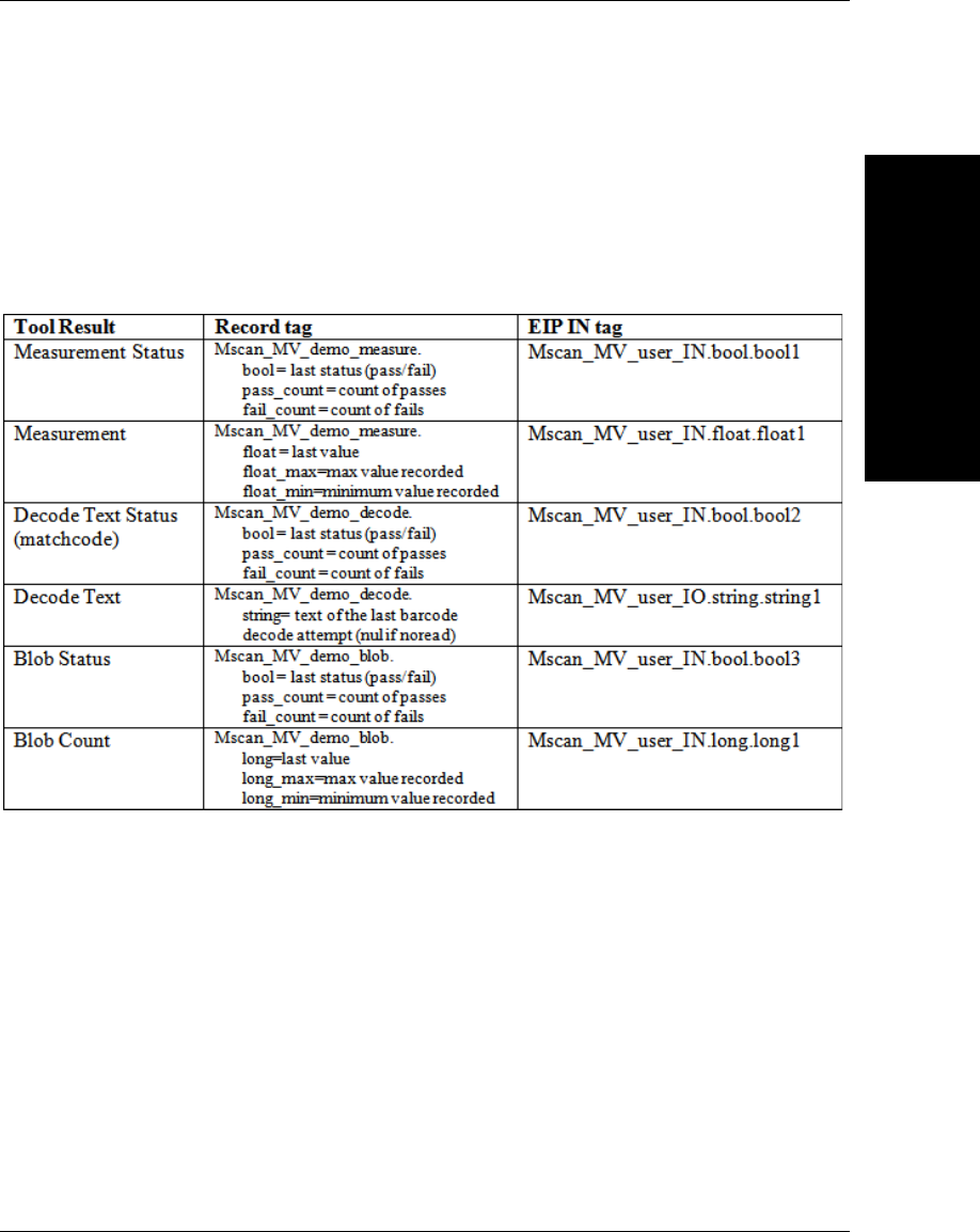
Demo PLC Code
G
Vision HAWK Smart Camera Guide G-13
Float101 = Measure lower tolerance
Float102 = Measure upper tolerance
String101 = Matchcode
Each tag set records the following data for each vision job tool result received in the
Inspection report:
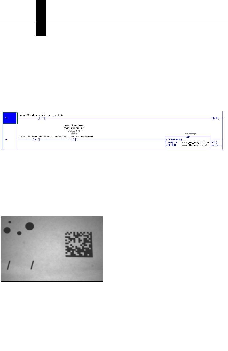
Appendix GDemo PLC Code
G-14 Vision HAWK Smart Camera Guide
User App Method
The user app can follow the demo code’s usage of these tags for further application logic
development.
During runtime, the user app can change the OUT data members, and observe the
change in tool status after a new trigger.
Specifically, the PLC integrator would typically modify the logic beginning at the following rungs:
Demo Target
The demo vision job uses predefined images. It is unnecessary to have the camera aimed
at any specific target. If preferred, the job can be changed to enable the camera’s image
sensor. In this case, the demo targets should be printed approximately 2.5 inches (63 mm)
wide by 1.6 inches (40 mm) tall, centered on white paper larger than the camera’s field of
view, and presented to the camera with the Data Matrix symbol on the right:
“Pass” Image
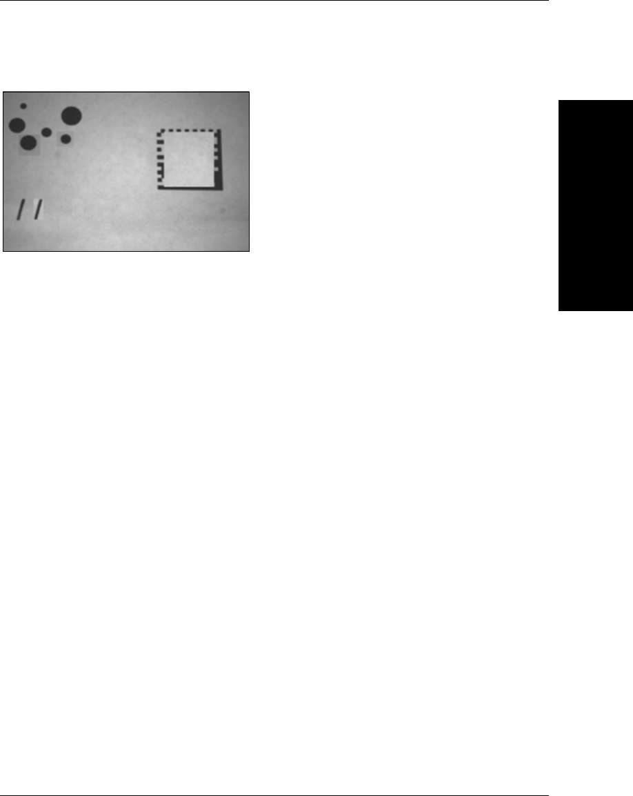
Demo PLC Code
G
Vision HAWK Smart Camera Guide G-15
“Fail” Image
Demo Code Usage
The user app example of the demo code watches for Data Valid. When it goes active, the
user app example processes the user IO data, updates each demo record with the results,
then uses ResetDataValid to clear DataValid.
Mscan_MV_IO_internal, Mscan_MV_ons_internal
Purpose
Used by the demo code to manage the camera.
User App Method
None. The user app must not attempt to read or write to this tag set.
Demo Code Usage
The demo code uses this tag set to abstract the on-the-wire control of the camera from the
user app.
Run the Camera: Runtime Operation of EtherNet/IP Demo
At this point in the evaluation, it is assumed that you have downloaded the demo vision job
to the camera, your PLC is running the EIP demo code and is exchanging data with the
camera. The PLC can now parameterize, trigger and monitor the camera over
EtherNet/IP.

Appendix GDemo PLC Code
G-16 Vision HAWK Smart Camera Guide

Vision HAWK Smart Camera Guide H-1
H
Serial Commands
H
APPENDIX H Serial Commands
This section provides descriptions of the serial commands that can be
sent to the camera via TCP (Telnet) port, AutoVISION Terminal, or
HyperTerminal.

Appendix HSerial Commands
H-2 Vision HAWK Smart Camera Guide
SET {tagname}{value}
Sets value of a global tag.
The tagname must correspond to one of the supported tags within the
device.
The value can contain spaces.
The command is terminated by a carriage return and/or line feed
character.
The value can be a list of comma-separated items to set a sequence of tags:
Send SET int1 1, 2, 3 to set int1 = 1, int2 = 2, int3 = 3.
The AVP service allows setting of step and datum information from the job
tree using forward slash ‘/’ in the symbolic name path. SET
avp/insp1/snapshot1/acq1/gain 2.0 paths are not case-sensitive and do
not need to be fully qualified if unique.
SET avp/acq1/gain 2.0 will set the same gain value if there is only one
acquire.
Control tags in the AVP service such as START, STOP, and TRIGGER act
as momentary switches. SET avp.start 1 is equivalent to the ONLINE
command. avp.start will reset immediately and always read as 0.
Success Return: On success will return !OK followed by an echo of the
command. For example:
!OK SET matchstring1 ABCD
Fail Return: On failure will return !ERROR followed by the reason for the
failure. For example:
!ERROR Tag matchstring66 not found
GET {tagname}
Gets value of a global tag.
The tagname must correspond to one of the supported tags within the
device.

Serial Commands
H
Vision HAWK Smart Camera Guide H-3
The command is terminated by a carriage return and/or line feed
character.
Include an index to get a single value from an array such as GET int1. If
the index is omitted, the full array of values will be returned in a comma-
separated list of values.
Send Get {tagname} to get the value of a tag within the global data
service. To get the value of a tag within another service, prefix the
tagname with the service name. For example, a GET {service.tagname}
command such as GET eip.input for the EIP input assembly.
The AVP service allows retrieval of step and datum information from the
job tree using forward slash ‘/’ in the symbolic name path. GET
avp/insp1/snapshot1/status paths are not case-sensitive and do not
need to be fully qualified if unique.
GET avp/snapshot1/status will return the same result if there is only one
inspection.
When issued against a step, GET avp/snapshot1 will return the values
for all datums.
Success Return: On success will return the value stored in the tag. For
example:
ABCD
Fail Return: On failure will return !ERROR followed by the reason for the
failure. For example:
!ERROR Tag matchstring66 not found
INFO {service.tagname or service}
Gets information about a tag or service.
INFO with no arguments gets a list of services.
INFO {service} gets a list of tags in that service.
INFO {service.tagname} gets attributes of the tag as well as a list of
subtags.

Appendix HSerial Commands
H-4 Vision HAWK Smart Camera Guide
The AVP service allows retrieval of step and datum information from the
job tree using forward slash ‘/’ in the symbolic name path.
INFOavp/insp1/snapshot1/status paths are not case-sensitive and do
not need to be fully qualified if unique.
INFO avp/snapshot1/status will return the same result if there is only
one inspection.
When issued against a step, INFO avp/snapshot1 returns properties of
the step, a list of child datums, and a list of child steps. Child steps are
indicated by a trailing forward slash.
GETIMAGE {-transfer=ymodem} {-type=failed}{-format=[jpg|png]}
{-quality=n} {-inspection=n} {woi=l,t,r,b}
Initiates serial transfer of inspection image.
-transfer=ymodem is not currently optional - only Ymodem protocol is
supported.
-type=failed to retrieve the last failed image. If omitted, the current image
is returned.
-format=[jpg|png] specifies the format of the image. If omitted, the image
format is JPG.
-quality=n specifies a JPG compression quality of n less than or equal to
100. The default quality is 80 if not specified.
-inspection=n specifies the inspection from which to retrieve an image.
The image will be from the first snapshot within that inspection. If not
specified, the image will be from the first inspection that does contain a
snapshot.
woi=left,top,right,bottom specifies a rectangular area of the image to be
included in the output image. If omitted, the full image buffer is returned.
ONLINE
Starts all inspections.

Serial Commands
H
Vision HAWK Smart Camera Guide H-5
OFFLINE
Stops all inspections.
TRIGGER {inspection index}
Triggers inspection. If {inspection index} is omitted, inspection 1 is
triggered.
VT (Virtual Trigger) Command
Triggers an inspection by pulsing a Virtual I/O point. For example:
VT 1
will return pulse VIO1. The inspection will run if it is configured to use VIO
1 as a trigger.
Syntax: VT [VIO Index]
• If specified, the VIO index must be in the allowed range for Virtual I/O
points within Visionscape. The virtual I/O line will be set high then low.
• If VIO Index is not specified, VIO1 is assumed
Success Return: Nothing is echoed on success of the VT command.
Fail Return: Return !ERROR followed by the reason for the failure. For
example:
!ERROR No such trigger
JOBSAVE [-slot=]n
Save job to slot n.
JOBLOAD [-slot=n][-r]
Load job from slot n.
-r = Start inspections.

Appendix HSerial Commands
H-6 Vision HAWK Smart Camera Guide
JOBDELETE [-slot=n]
Delete job in slot n.
JOBINFO [[-slot=]n][-v]
Get job summary or info about slot n.
-v = Verbose. This option shows the amount of space that would be freed
if the job were deleted. It also lists the total disk space and free disk
space.
JOBBOOT {-slot=n}
Set bootup job slot n.
JOBDOWNLOAD [-transfer=]{YMODEM}
Download .avz job packaged via transfer method.
JOBDELETE -all
Delete all jobs in job slots.
Important: Does not delete the current job loaded in camera memory.
GET SYSTEM.JOBSLOT
Retrieve the slot of the current job. Note that the current job in the camera
can be loaded from a job slot or the PC. If it isn’t loaded from a job slot
then this command will return -1.
ASSIGN [-automap] [-u] [-name=avp] [-range=n] [-count=n]
{tagname}
Assign marks a tag or range of tags as in use by an application. Once
marked as in use, the application will avoid those tags when attempting to
auto-assign another tag range.

Serial Commands
H
Vision HAWK Smart Camera Guide H-7
-automap = find the first unused set of 'n' tag indices
-u = un-assign tag
-name = name of application that is taking assignment
-range = maximum number of indices to search when -automap is used
-count = number of consecutive tag indices to assign
-tagname = tag to perform assignment on
For example, ASSIGN -automap -name=avp -range=10 -count=2 int101
will find the first set of 2 unassigned integers starting from int101 up to
int110 and mark them as assigned by 'avp'. The index value is returned.

Appendix HSerial Commands
H-8 Vision HAWK Smart Camera Guide

Vision HAWK Smart Camera Guide I-1
I
Vision HAWK Boot
Modes
I
APPENDIX I Vision HAWK Boot Modes
This section describes the Vision HAWK’s Diagnostic Boot Mode and
Boot Error Mode.

Appendix IVision HAWK Boot Modes
I-2 Vision HAWK Smart Camera Guide
Diagnostic Boot Mode
The Vision HAWK supports a special boot mode used for diagnostics and
recovery. There are two ways in which the camera can be put into this mode:
1. This method requires an Ethernet connection between the host PC
and Vision HAWK. Power-on the unit and hold the AutoVISION button
down until the green flash illuminates once. For C-Mount versions,
hold the button down for approximately 30 seconds. The unit is now
configured for IP address 192.168.0.10 with subnet mask
255.255.255.0. Establish a telnet connection between the host PC
and Vision HAWK. The [SAFE-KERNEL] prompt is displayed.
2. This method requires a QX-1 and a serial connection between the
host PC running a terminal emulator and Vision HAWK camera.
Power-on the unit and hold down the Tab key down for several
seconds. The unit will boot to a [SAFE-KERNEL] prompt with
communication settings of 115200, N, 8, 1 (baud, parity, data bits,
stop bits).
Once the unit is booted, there are many possible actions the user can
take. However, the most useful actions are listed below.
In rare situations, the boot job executed at camera startup can cause
unexpected behavior. If this is the suspected case, it is possible to disable
loading and running of the boot job at startup using the following
command.
[SAFE-KERNEL] BP_UpdateStartupOptions(0, 0)
Note that the loading and running of the boot job is automatically re-enabled
the next time a job is saved to camera flash from AutoVISION or
FrontRunner.
At boot time, the system configures itself using a set of information known
as boot parameters. To obtain a list of the current configuration’s boot
parameters, issue the following command:
[SAFE-KERNEL] BP_Dump()
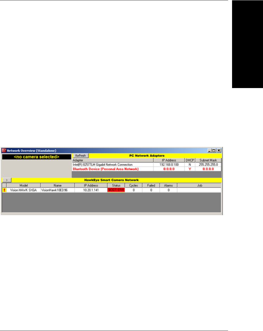
Vision HAWK Boot
Modes
I
Vision HAWK Smart Camera Guide I-3
Should your device need to be configured with different IP information, follow the example
below and substitute the appropriate settings for IP address, subnet mask, and gateway
address, respectively.
[SAFE-KERNEL] BP_UpdateIP(“192.168.0.10”, “255.255.255.0”, “192.168.0.100”)
It is possible to configure the system to acquire its IP address via DHCP or to use a static
IP address. Issue the following command with a ‘0’ for static IP or a ‘1’ for DHCP.
[SAFE-KERNEL] BP_UpdateDHCP(0)
Boot Error Mode
The Vision HAWK enters an error mode on boot if it’s unable to fully load Visionscape.
This mode is visually displayed to the user by flashing the Error LED along with the
OUTPUT 1, OUTPUT 2, and OUTPUT 3 LEDs on the front of the unit. Additionally, this
mode is represented as a “BOOT_ERR” in the Network Overview tool.
If you encounter this error condition, you will need to reload the firmware using the Smart
Camera Firmware Update Tool.

Appendix IVision HAWK Boot Modes
I-4 Vision HAWK Smart Camera Guide
