Visionscape Programmer's Kit (VSKit) Manual Visionscapevskitmanual
2016-08-18
: Microscan Visionscapevskitmanual visionscapevskitmanual center
Open the PDF directly: View PDF ![]() .
.
Page Count: 364 [warning: Documents this large are best viewed by clicking the View PDF Link!]
- Visionscape® Programmer’s Kit (VSKit) Manual
- Contents
- PREFACE Welcome
- CHAPTER 1 Introduction
- CHAPTER 2 Jobs, Steps and Datums
- Jobs and Job Files
- Steps
- Datums
- Steplib and The Step Object
- Using StepBrowser to Look Up Symbolic Names
- The JobStep Object
- The VisionSystemStep Object
- Step Object Properties
- Step Object Methods
- Datum Object Properties
- Datum Object Methods
- Step Handles: Converting to Step Objects
- CHAPTER 3 Talking to Visionscape Hardware: VsCoordinator and VsDevice
- Introduction to Visionscape® Device Objects (VSOBJ.DLL)
- Connecting Jobs to Visionscape® Devices
- What Else Can I Do With Device Objects?
- A Detailed Look at VsDevice
- Obtaining Device Information
- Namespace Information
- VsNameNode
- A Detailed Look at VsCoordinator
- Device Collection
- DeviceFocusSet
- Grouping Controls Using GroupID
- Device Focus Property
- DeviceFocusSetOnDiscovery
- Finding a Device by Name or IP
- OnDeviceDiscovered Event
- Using Message Broadcasting to Simplify Application Design
- Global Strings
- UpdateUI Method
- LogMessage and the Debug Window
- Using VsFunctions to Synchronize UI Elements
- Getting Information About Local Network Interface Controllers
- VsCoordinator Reference
- VsDevice Reference
- CHAPTER 4 Viewing Images and Results with VSRunView Control
- CHAPTER 5 Using VsKit Components
- CHAPTER 6 Using Report Connections
- CHAPTER 7 I/O Capabilities
- CHAPTER 8 Display and Setup Components
- APPENDIX A Examples
- Example 1 — Load and Run
- Example 2 — Monitor a Smart Camera
- Discover, Connect to, and Monitor a Running Smart Camera
- Add References and Components to your project
- Name Your Project and Form
- Drop the VsRunView Control on Your Main Form
- Add Global Variables to frmMain
- Add Code to the Form_Load Event
- Attach VsRunView in the OnDeviceFocus Event
- Size the VsRunView Control in Form_Resize
- Compile and Run
- Extras
- APPENDIX B Legacy Controls
- APPENDIX C Advanced Datums
- APPENDIX D Installed Sample Applications

Visionscape® Programmer’s Kit
(VSKit) Manual
84-100027-02 Rev D
v7.0.1, June 2014
Copyright ©2014
Microscan Systems, Inc.
Tel: +1.425.226.5700 / 800.762.1149
Fax: +1.425.226.8250
ISO 9001 Certified
Issued by TüV USA
All rights reserved. The information contained herein is proprietary and is provided solely for the purpose of
allowing customers to operate and/or service Microscan manufactured equipment and is not to be released,
reproduced, or used for any other purpose without written permission of Microscan.
Throughout this manual, trademarked names might be used. We state herein that we are using the names to the
benefit of the trademark owner, with no intention of infringement.
Disclaimer
The information and specifications described in this manual are subject to change without notice.
Latest Manual Version
For the latest version of this manual, see the Download Center on our web site at:
www.microscan.com.
Technical Support
For technical support, e-mail: helpdesk@microscan.com.
Warranty
For current warranty information, see: www.microscan.com/warranty.
Microscan Systems, Inc.
United States Corporate Headquarters
+1.425.226.5700 / 800.762.1149
United States Northeast Technology Center
+1.603.598.8400 / 800.468.9503
European Headquarters
+31.172.423360
Asia Pacific Headquarters
+65.6846.1214

Visionscape Programmer’s Kit (VSKit) Manual iii
Contents
PREFACE Welcome vii
Purpose of This Manual vii
Manual Conventions vii
Related Publications vii
CHAPTER 1 Introduction 1-1
Visionscape Architecture 1-1
Visionscape Devices 1-3
Programming Language Considerations 1-4
Common User Interface Scenarios 1-4
CHAPTER 2 Jobs, Steps and Datums 2-1
Jobs and Job Files 2-1
Steps 2-1
Datums 2-2
Steplib and The Step Object 2-2
Using StepBrowser to Look Up Symbolic Names 2-30
The JobStep Object 2-31
The VisionSystemStep Object 2-34
Step Object Properties 2-36
Step Object Methods 2-39
Datum Object Properties 2-43

Contents
iv Visionscape Programmer’s Kit (VSKit) Manual
Datum Object Methods 2-47
Step Handles: Converting to Step Objects 2-48
CHAPTER 3 Talking to Visionscape Hardware: VsCoordinator
and VsDevice 3-1
Introduction to Visionscape Device Objects (VSOBJ.DLL) 3-1
Connecting Jobs to Visionscape Devices 3-6
What Else Can I Do With Device Objects? 3-9
A Detailed Look at VsDevice 3-13
Obtaining Device Information 3-17
Namespace Information 3-21
VsNameNode 3-23
A Detailed Look at VsCoordinator 3-28
VsCoordinator Reference 3-37
VsDevice Reference 3-43
CHAPTER 4 Viewing Images and Results with VSRunView
Control 4-1
Visionscape Runtime Toolkit 4-1
A Simple Application 4-7
Other Features of VsRunKit 4-10
CHAPTER 5 Using VsKit Components 5-1
Visionscape Control Toolkit 5-1
CHAPTER 6 Using Report Connections 6-1
The AvpReportConnection Object 6-1
Handling Inspection Reports: The AvpInspReport Object 6-11
Inspection Report Details 6-17
CHAPTER 7 I/O Capabilities 7-1
The AVP I/O Library ActiveX Control 7-1

Contents
Visionscape Programmer’s Kit (VSKit) Manual v
CHAPTER 8 Display and Setup Components 8-1
Buffer Manager ActiveX Control 8-2
Setup Manager ActiveX Control 8-14
Job Manager ActiveX Control 8-40
Datum Grid Active X Control 8-51
StepTreeView ActiveX Control 8-54
APPENDIX A Examples A-1
Example 1 — Load and Run A-1
Example 2 — Monitor a Smart Camera A-8
APPENDIX B Legacy Controls B-1
Calibration Manager ActiveX Control B-1
Datum Manager ActiveX Control B-11
Message Scroll Window ActiveX Control B-14
Runtime Manager ActiveX Control B-18
Converting Runtime Manager Applications to New Components B-18
Runtime/Target Manager ActiveX Control B-19
APPENDIX C Advanced Datums C-1
The DMR Tool’s VerifyDetails Datum C-1
Changing the OCV Tool Layout String Using the “LayoutInfo” Datum C-7
Changing the Camera Selection with the CamDefDm Datum C-10
APPENDIX D Installed Sample Applications D-1
Installing the Samples D-1
AppRunner Source Code D-1
VSRUNKIT Sample D-2
VSKIT Samples D-2
Extras D-3

Contents
vi Visionscape Programmer’s Kit (VSKit) Manual

Visionscape Programmer’s Kit (VSKit) Manual vii
Preface
PREFACE Welcome
Purpose of This Manual
This manual describes how to use VSKit, which is a collection of libraries
that aid in the development of user interface applications for Visionscape
products.
Manual Conventions
The following typographical conventions are used throughout this manual:
• Items emphasizing important information are bolded.
• Menu selections, menu items and entries in screen images are
indicated as: Run (triggered), Modify..., etc.
Related Publications
This guide provides details on programming the Visionscape application.
However, for additional information, refer to the following resources:
• Core Visual Basic 5
by Cornell and Jezak
© 1998 Prentice Hall
ISBN #0-13-748328-7

Preface
viii Visionscape Programmer’s Kit (VSKit) Manual
• Mastering Visual Basic 5
by Evangelos Petroutsos
© 1997 Sybex
ISBN #0-78-211984-0
• Microsoft Visual Basic 5.0 Programmer’s Guide
© 1997 Microsoft Press
ISBN #1-57-231604-7
• Learning DCOM
by Thuuan L. Thai
© 1999 O'Reilly and Associates
ISBN #1565925815
Prerequisite Reading for C++ Programming
The following publications provide supplemental guidance in C++
programming. The first two are critical to your understanding, and the
second two are useful:
• ATL COM Programmer's Reference
by Dr. Richard Grimes
© 1998 Wrox Press
• Beginning ATL COM Programming
by Grimes and Stockton et al
© 1998 Wrox Press
ISBN# 1-861000-11-1
• Professional ATL COM Programming
by Dr. Richard Grimes
© 1998 Wrox Press
ISBN #1-861001-40-1

Visionscape Programmers Kit (VSKit) Manual 1-1
1
Introduction
1
CHAPTER 1 Introduction
Visionscape® is a comprehensive environment for developing and
deploying a wide variety of machine vision applications using
Visionscape® Vision Processing hardware.
Visionscape® Architecture
The Visionscape® architecture is open, allowing multi-level access to a
wide variety of users ranging from factory-floor operators who monitor
vision operation, to engineers who set up, install, and/or modify vision
applications, to system integrators and low-level software developers who
develop custom vision applications.
After you install Visionscape®, you have a library of components that
allow programming access to the AVP files you’ve created in FrontRunner
or AppFactory as well as to Visionscape® hardware components. With
these powerful components, you can develop complete custom
applications in Visual Basic (typically) or any other language that supports
ActiveX (COM) components.
As a Visionscape® programmer, you may customize access to underlying
components and provide specific end-user access, such as training and
running pre-configured jobs. Programmers can also utilize the
components to access specific features, such as live video, calibration,
job creation, training, and inspection execution.
Chapter 1Introduction
1-2 Visionscape Programmers Kit (VSKit) Manual
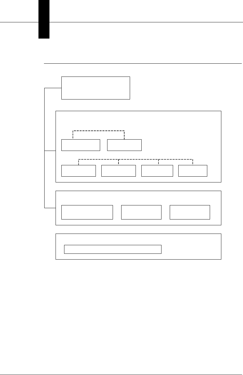
FIGURE 1–1. Layered Architecture
Figure 1–1 shows a basic diagram of the Visionscape® component
hierarchy. At the topmost level (Visionscape® User Interface) are the end-
user applications running on a host PC using Windows® 2000 or
Windows® XP. Typically, these applications are written in Visual Basic.
These environments allow programmers to quickly develop and deploy
vision applications in a point-and-click fashion.
The next level down shows the Visionscape® Components layer. These
high-level software components (ActiveX Controls) have a user interface
to them, and can be dropped onto a Visual Basic form to provide high
level functionality such as watching images at runtime, allowing a user to
grab and move tools in the image, adjust their parameters, etc.
FrontRunner / AppRunner
Custom GUIs
Visionscape Components (ActiveX Controls )
VsRunKit VsKit
Buffer Manager Setup Manager Job Mgr Runtime
Manager
High Level components
Visionscape Libraries (ActiveX DLLs)
Visionscape Step Vision
Library (steplib.dll)
Visionscape Device
Objects (vsobj.dll)
Visionscape IO
access (avpiolib.dll)
Visionscape Hardware Layer
Visionscape Vision Processor Hardware and Drivers
Visionscape User Interfaces

Visionscape® Devices
Introduction
1
Visionscape Programmers Kit (VSKit) Manual 1-3
Table 1–1 lists classifications and other information pertaining to these
controls.
The next level shows the Visionscape® Libraries layer. These are
software libraries (ActiveX DLLs) that encapsulate the core vision system
functionality required to develop and deploy vision applications. These
libraries have no user interface associated with them. This layer includes
the actual tools, such as image acquisition, image pre-processing, feature
extraction, measurement computation, expression evaluation, control,
and I/O. These tools can run either directly on AVP hardware (smart
cameras) or on the host PC with Visionscape® GigE Cameras.
Finally, at the lowest level is the Hardware Driver layer. No direct
programming access is required (or allowed) at this level. Our higher level
libraries deal with the hardware for you, insulating you from the
complexities of low level device drivers.
Visionscape® Devices
When we refer to a Visionscape® Device in this manual, we are referring
to the actual vision hardware you purchased from us. Visionscape®
Devices fall into two categories:
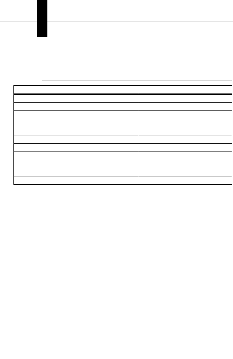
TABLE 1–1. ActiveX Component Classifications
ActiveX
Controls Function Reference
VsRunView A flexible control to handle displaying multiple snapshots
and multiple sets of results at Runtime
Chapter 4
VsKit A flexible set of UI controls. Chapter 5
Avp I/O Library Manipulates I/O. Chapter 7
Buffer Manager Used primarily for image display. Chapter 8
Datum Manager Used for editing step parameters. Appendix B
Job Manager Edits jobs, inserts/deletes steps, and edits step
parameters.
Chapter 8
Runtime Manager Controls inspections at runtime, I/O, results, and runtime
image display.
Appendix B
Setup Manager Trains and tries out inspections in the job. Chapter 8

Chapter 1Introduction
1-4 Visionscape Programmers Kit (VSKit) Manual
• Smart Cameras — These devices are cameras with the Vision
Processing smarts built right in. You will generally be making a
network connection to the smart camera and using it to download
your AVP, as well as to upload images and results. Jobs run on the
smart camera independent of the PC. In fact, once you’ve
downloaded a job to a smart camera and started it running, you can
disconnect your PC and the smart camera will continue to run.
• GigE Cameras — With GigE cameras, the PC becomes the Vision
Processor. Your Jobs will run under Windows; they do not run on the
cameras themselves. These cameras acquire images and provide
I/O.
Programming Language Considerations
Visual Basic 6, Service Pack 6
This manual describes how to use Visionscape® software components
with Visual Basic 6, service pack 6. This is the only software supported by
Visionscape®. The objects in these libraries use the Component Object
Model (COM), and Visual Basic’s support for COM is unequaled among
programming languages. C++ and .NET are not supported.
Common User Interface Scenarios
What Visionscape® components do you need to learn about in order to
create your user interface? The answer to this question depends on
several factors:
• What does your user interface need to do? Just display images?
Display images and gather inspection result data? Allow you to
change between different Jobs? Allow you to modify the Job
parameters?
• What type of Visionscape® hardware does your UI need to support?
The following are some common user interface scenarios, and a “big
picture” overview of the components and tasks required to implement
them.

Common User Interface Scenarios
Introduction
1
Visionscape Programmers Kit (VSKit) Manual 1-5
Scenario 1 — Simple GigE Camera Runtime User Interface
This has historically been the most common user interface scenario. You
have a Visionscape® GigE Camera connected to your PC, and you simply
want to load an AVP that you’ve created and tested in FrontRunner, start
it running, and then display the images and perhaps do some special
handling of the uploaded results. This scenario generally applies to GigE
Cameras but it also works with smart cameras; the code would be
identical. This is what you’ll need to do:
1. Use the VsCoordinator object to query the Visionscape® hardware in
your PC, and find your camera in its Devices collection (see “Device
Collection” on page 3-28). This will return a reference to a VsDevice
object, which represents your camera.
2. Call the VsDevice object’s DownloadAVP method (see “Downloading
a Job” on page 3-14 and “Download / Upload Job” on page 3-44),
passing in the path to your AVP file. This will load the Job into
memory and connect it to your hardware in one step.
3. Use the VsRunView control to view all of the images and results in
your Job (Chapter 4, “Viewing Images and Results w/VSRunView
Control”). Simply drop this control onto your application’s main form,
and call its AttachDevice method, passing in the name of the device
you are using. This control will automatically add a button to its
toolbar for every snapshot in your Job, and you can then choose to
watch one or multiple snapshots at the runtime. All inspection
counters and uploaded results are also displayed in a collapsible
panel at the bottom of the control. All of this with just one line of code.
4. If your UI needs to collect and/or process the uploaded inspection
results (measurement data, tool statuses, flaw data, decoded strings,
etc.), then you can receive that via VsRunViews OnNewReport event.
You simply need to set the ReportEventEnabled property to True
(Chapter 4).
Hardware Visionscape GigE Camera
Language Visual Basic 6.
Goal To create a runtime only user interface that loads a vision
Job, gets it running, and then displays images and handles
inspection results for one or more cameras.

Chapter 1Introduction
1-6 Visionscape Programmers Kit (VSKit) Manual
5. Start all the inspections running by calling VsDevice’s StartInspection
method (Chapter 3).
Scenario 2 — Smart Camera Runtime Monitoring
Application
This is the typical style of user interface when dealing with smart
cameras. You will use FrontRunner to build your Job, download it and
flash it to your smart camera, and then start it running. At that point, your
smart camera is ready to run independently of the PC. For this reason,
your UI will generally not need to load an AVP and download it at startup
time, as there will already be a job running. You will simply want to
connect to the camera, and start uploading images and results in order to
monitor its performance. This requires even less code than scenario #1.
Here’s what you’ll need to do:
1. Use the VsCoordinator object to discover your smart camera on your
network. This may take a few seconds (refer to Chapter 3, “Talking to
Visionscape Hardware: VsCoordinator and VsDevice”), so call the
DeviceFocusSetOnDiscovery method, passing in the name of your
smart camera.
You will receive the OnDeviceDiscovered event from VsCoordinator when
your camera is discovered. This event will pass you a VsDevice object,
this object represents your smart camera.
Use the VsRunView control to view your images and results. Simply call
its AttachDevice method, passing in the name of your smart camera
(Chapter 4). You can also set the ReportEventEnabled property to True,
and then you will receive the OnNewReport event for every new
inspection report received, allowing you to process the inspection results,
if need be.
Hardware Smart Camera
Language Visual Basic 6.
Goal To create a runtime only user interface that monitors
the results and images of an already running smart
camera.

Common User Interface Scenarios
Introduction
1
Visionscape Programmers Kit (VSKit) Manual 1-7
That’s all you need to do. If you want your UI to provide the ability to
change the running AVP on the smart camera, then you can do this by
simply calling the VsDevice object’s DownloadAVP method.
Scenario 3 — A Runtime User Interface w/Job Analysis
Capability
The only difference between this scenario and scenario #1 is the desire to
have the AVP loaded in your application so that you can scan the Job in
order to verify certain key settings, or the presence of certain Steps.
1. Create an instance of a JobStep object, and call its Load method to
load in your AVP file (Chapter 2).
2. With the AVP loaded, your JobStep will contain a collection of
VisionSystem Steps (Chapter 2); get a reference to the first.
3. Use the VsCoordinator’s Devices collection to select the Device you
will be connecting to. This will return you a reference to a VsDevice
object, which represents your hardware (Chapter 3).
4. Call the Download method of VsDevice, passing it the reference to
the VisionSystemStep from your Job. This is similar to the
DownloadAVP method, but it takes in a reference to a
VisionSystemStep from an already loaded Job, rather than the path
to the AVP file (Chapter 3).
5. Use the VsRunView control (see “The VsRunView Control” on
page 4-1) to view your images and results. Simply call its
AttachDevice method, passing in the name of your smart camera.
You can also set the ReportEventEnabled property to True, and then
you will receive the OnNewReport event for every new inspection
report received, allowing you to process the inspection results if need
be.
Hardware Any
Language Visual Basic 6.
Goal To create a runtime only user interface that loads an AVP
file, has the ability to scan that AVP for certain Steps or
Datum settings, downloads and starts all inspections on a
particular device, and then monitors the results and
images.

Chapter 1Introduction
1-8 Visionscape Programmers Kit (VSKit) Manual
6. Start all inspections by calling the StartInspection method of
VsDevice (Chapter 3).
Scenario 4 — A More Complex Runtime User Interface
w/Maximum Control Over Image and Results Upload
In the previous scenarios, we recommended that you use the VsRunView
control to display your images and results. You may decide that this
component doesn't give you enough control over the look and feel of your
UI, or perhaps you just prefer to do it yourself. In each of these cases, you
will not want to use the VsRunView control. Instead, you can create what
we call Report Connections to the device, and handle receiving images
and results yourself. Then, you would use the Buffer Manager control to
display the images, and any controls you wish to display the results. The
following is the most likely series of steps to follow in order to implement
this type of UI:
1. Either load your AVP from disk using the JobStep (see “JobStep” on
page 2-2), or use the VsDevice’s DownloadAVP method and specify
the path to your AVP file (see “Downloading a Job” on page 3-14). For
maximum flexibility, we recommend you load the job into a JobStep,
and then connect it to your hardware by passing the VisionSystem
step to the Download method of VsDevice.
2. Create a Report Connection for every inspection in your Job by
creating instances of the AvpReportConnection object (see “The
AvpReportConnection Object” on page 6-1). You will connect the
object by calling its Connect method, passing the name of the device
and the index of the inspection you are connecting to.
3. Scan the inspections in your Job to determine how many Snapshots
are present in each, and then add the image buffers of each snap to
Hardware Any
Language Visual Basic 6.
Goal To create a runtime only user interface that loads an AVP
file and prepares it to run on a particular Visionscape®
device. This user interface would have very specific goals
regarding how images should be displayed, what images
should be displayed, and how the inspection results should
be handled and/or displayed.

Common User Interface Scenarios
Introduction
1
Visionscape Programmers Kit (VSKit) Manual 1-9
its corresponding report connection. Report connections do not
include the images from the inspection by default, so you must add
them (see “Adding Images to your Report” on page 6-7).
4. Add a Buffer Manager control to display a snapshot image, or multiple
Buffer Manager controls to display multiple snapshots simultaneously.
Chapter 6 demonstrates how to display images with Buffer Manager,
Chapter 8 describes the Buffer Manager in more detail.
5. Start your inspections running using the StartInspection method of
VsDevice (Chapter 3).
6. To display images at runtime, you will handle the OnNewReport
event from each ReportConnection (Chapter 6). This will pass you an
AvpInspReport object, which will contain a collection of the images
you requested in step 3. These images take the form of our BufferDm
object, and they can be displayed by simply passing the Handle
property to the Buffer Manager’s Edit method. You will also perform
any processing on the uploaded results in this event.
Using the above approach requires a little more work than using the
VsRunView control, but it gives you maximum control over how to display
your images, as you can choose how to layout the Buffer Manager
controls on your form, and it also allows you to control where and how
your inspection results are displayed.
Application Extras
The previous scenarios describe basic applications. But what about other
capabilities:
• IO Capabilities — “I need to be able to get/set IO values, and/or be
notified of transitions on certain key IO points, physical or virtual”.
Refer to “The AVP I/O Library ActiveX Control” on page 7-1 for a
description of the AvpIOClient object.
• Setup Capabilities — My UI must allow the user to make adjustments
to the inspections, acquire Live Video, move ROIs, retrain Steps,
and/or change parameters. Refer to Chapter 8, “Display and Setup
Components” for a description of the Setup Manager and Job
Manager components.

Chapter 1Introduction
1-10 Visionscape Programmers Kit (VSKit) Manual

Visionscape Programmer’s Kit (VSKit) Manual 2-1
2
Jobs, Steps and
Datums
2
CHAPTER 2 Jobs, Steps and Datums
In this chapter, we’ll discuss Jobs, and the Steps and Datums that
construct them. We’ll explain how to load a Job from disk, how you can
then access each of the Steps within that Job, and how you can get and
set any of the parameters (what we call “Datums”) of those steps. We’ll
describe the Step and Datum interfaces, and how to use them to find
Steps, add or remove Steps, and how to get and set Datum values within
a Step.
Jobs and Job Files
We use the term “Job” to refer to any Visionscape vision inspection
program that you have created from our FrontRunner or AppFactory
engineering interfaces, or from code (more about that later). When saved
to file, a Job will always have the AVP file extension. For that reason, we
also refer to Job files as AVPs. A Job is essentially a collection of Steps in
a tree structure.
Steps
A Step is a single “tool” in a Vision Program. A user inserts Steps into his
or her Job in order to add functionality. A Step may run a vision algorithm
like the Blob Step or Fast Edge Step, it may perform measurements like
the Pt to Line Distance Step, or it may perform logical operations like the
IF Step or the VarAssign Step. Each Step contains a collection of Datums
that configure its specific functionality.
Chapter 2Jobs, Steps and Datums
2-2 Visionscape Programmer’s Kit (VSKit) Manual
Datums
A Datum is a generic representation of a Step parameter. It encapsulates
all types of data, such as integers, floating point values, arrays, etc. The
“High Threshold” parameter of the Blob Step is an example of a Datum.
FIGURE 2–1. Example of a Job and the Steps and Datums Within It
Steplib and The Step Object
Accessing Jobs and Steps in your Visual Basic program requires you to
add a Reference to the ActiveX DLL Steplib.dll. In your Visual Basic 6
project, you go to the Project menu, select “References” and check the
following item:
+Visionscape Steps: Step Vision Library
JobStep
We’ll start by talking about the JobStep object. As we said above, a Job is
your vision program, and it contains all of the Steps and Datums that
make up your vision program. So, you use the JobStep object to load and
save Jobs from disk. Here’s an example of how you would load the
sample “example_datamatrix.avp” file (installed with Visionscape) in your
Form Load event:
Private m_Job as JobStep 'declare a variable of type JobStep
Private Sub Form_Load()
'CREATE THE JOB STEP OBJECT
{
The Job Tree
Steps
Datums for the
FastEdge_Left Step

Steplib and The Step Object
Jobs, Steps and
Datums
2
Visionscape Programmer’s Kit (VSKit) Manual 2-3
Set m_Job = New JobStep
'load the job file
m_Job.Load "C:\Vscape\Tutorials and
Samples\Sample Jobs\Data
Matrix\example_datamatrix.avp"
End Sub
In this example, we simply called the Load method of JobStep, and
passed in the path to our AVP file. The AVP file is now loaded in memory,
contained within our JobStep variable, m_Job. Using methods and
properties of the JobStep object, we can access any of the Steps within
the loaded Job, and any of their Datums. The JobStep object is a
specialized form of the more generic Step object. To use C++
terminology, you would say that JobStep is derived from the Step Object.
This means that the JobStep contains all of the methods and properties of
the Step object, but also adds a few of its own, like the Load method
shown in our example. Over the course of this chapter, we’ll talk about
several other custom Step objects (like the VisionSystemStep), but you
should understand that all of these objects are built on top of the generic
Step object and, therefore, contain all of its capabilities.
The Step Object
As we just described, the Step Object is the generic object (the base
class if you will) upon which all Steps are built. You should understand the
following key concepts about Steps.
Steps Are Collections
Each Step is a collection, just like the Visual Basic collection object. It
holds a collection of the child steps that were inserted inside of it when the
Job was built. So, you can enumerate the Steps of your Job just as you
would the elements of any collection object. Consider the example Job
tree in Figure 2–2, and the parent-child relationships of each step:
Chapter 2Jobs, Steps and Datums
2-4 Visionscape Programmer’s Kit (VSKit) Manual
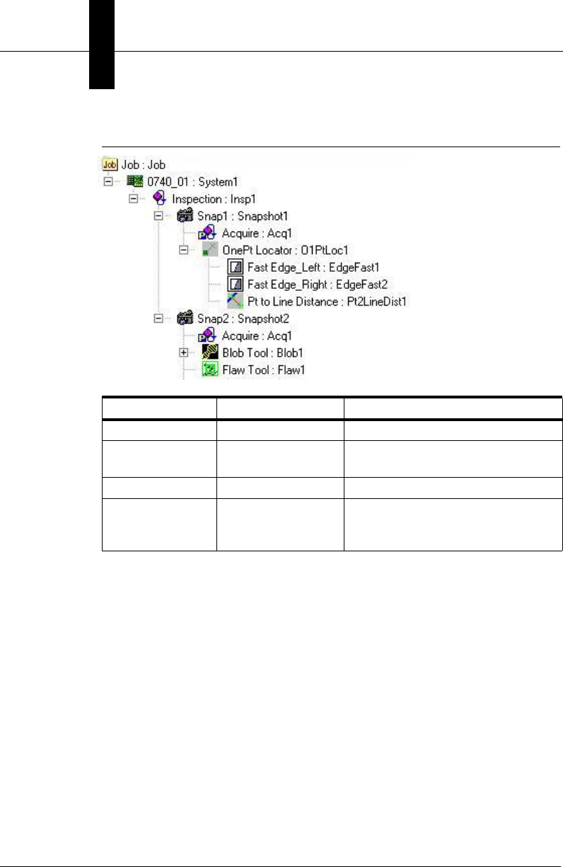
FIGURE 2–2. A Job Tree is a Collection of Collections
So, let’s assume that the Job we loaded from disk matches the Job
tree shown in Figure 2–2. As you can see, the Job Step is always the
top-most Step in the tree. The Job will always contain one or more
VisionSystem steps in its collection. So, if we wanted to access the
first VisionSystem step in the Job, we could simply do the following:
Dim vs as Step
Set vs = m_Job(1) ‘collections are 1 based
And, if we wanted to iterate through all the VisionSystem steps, we
could do the following:
Parent Step Child Count Child Steps in the Collection
0740_01 1 Inspection:Insp1
Inspection 2 Snap1:Snapshot1
Snap2:Snapshot2
Snap1 ‘ OnePtLocator:O1PtLoc1
OnePtLocator 3 Fast Edge_Left:EdgeFast1
Fast Edge_Right:EdgeFast2
Pt to Line Distance:Pt2LineDist

Steplib and The Step Object
Jobs, Steps and
Datums
2
Visionscape Programmer’s Kit (VSKit) Manual 2-5
Dim vs as Step
For each vs in m_Job
Debug.print “The name of the step is “ and vs.name
next
The Step Object Provides Many Properties That Describe
the Step
These include the Step’s Name, Symbolic Name, the type of Step (Blob,
Snapshot, Flaw, etc.), what category it falls under, is it trainable, is it
trained, etc. For more information, see “The Major Properties That
Describe A Step” on page 2-5 and “Step Object Properties” on page 2-36.
The Step Object Has Many Methods for Finding Child Steps
It’s possible to find any step within a Job tree by simply using the
collection methods of the Step Object, but this can sometimes require a
fair amount of code. You may want to simply find all the Snapshots in your
Job, or find the first Step named “My Fast Edge Tool”. Fortunately, the
Step Object provides several flexible methods that locate Steps quickly.
We will cover this in more detail later in this chapter.
Use Step Object to Add and Remove Steps From Your Job
The Step Object provides methods that allow you to create new steps and
delete existing ones. It’s actually possible to create an entire Job from
code if you wish (though this is not generally recommended). Refer to
“Adding and Removing Steps” on page 2-10 for more information.
Every Step Contains a Collection of Datums
The Datums property of Step Object is a collection that contains a list of
all of the Datums for that Step. You can get and set any of the values of
any Step parameter via the Datum interface. More on that later.
Now, let’s cover each of these topics in more detail.
The Major Properties That Describe A Step
The Step Object has many properties and methods, but the following
properties are the most commonly used, and the ones that provide the
most valuable information to describe a Step.
Chapter 2Jobs, Steps and Datums
2-6 Visionscape Programmer’s Kit (VSKit) Manual
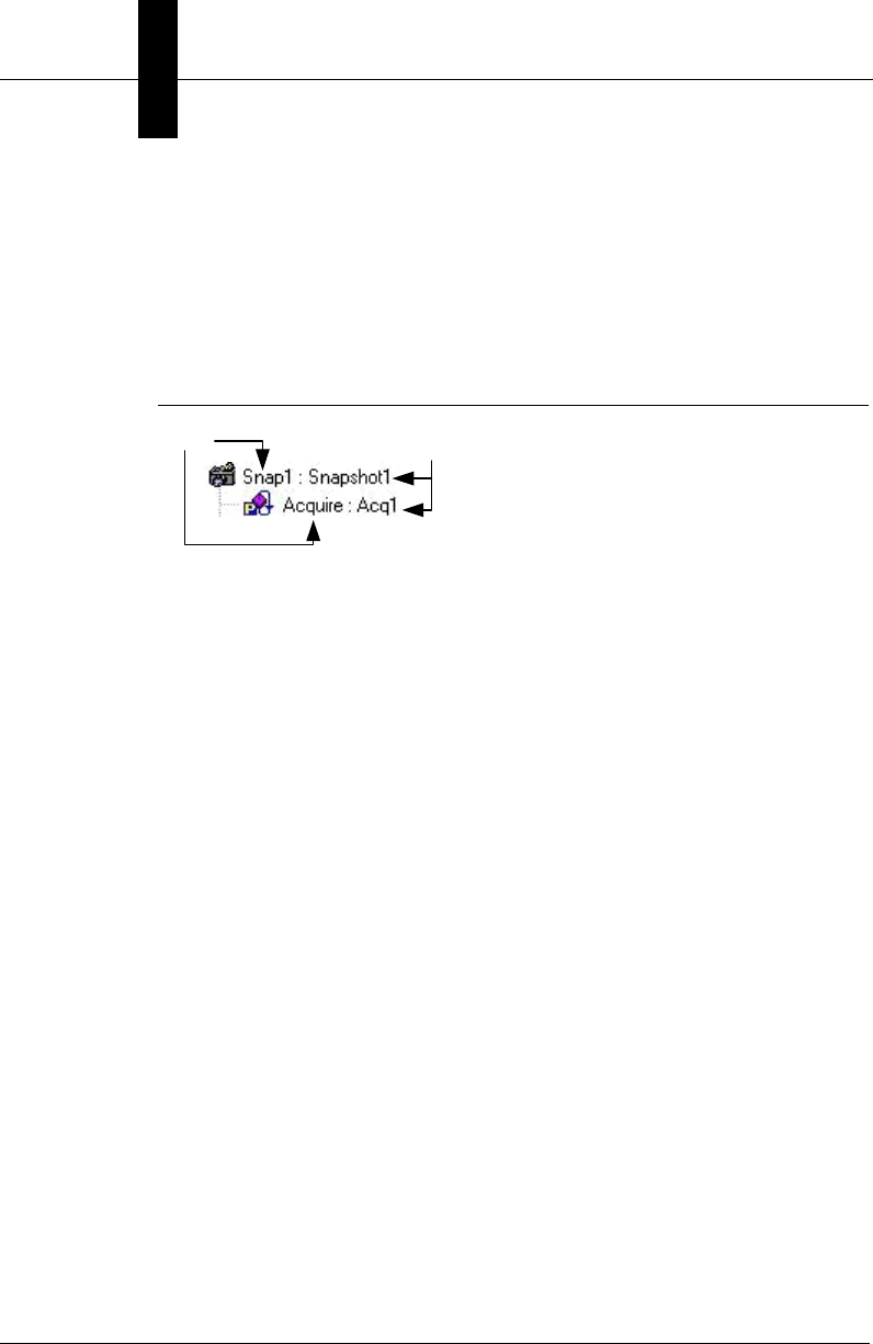
• Name — Holds the name the user assigned to the step. You can
change this name via your Visual Basic code, and/or the user may
change it while in FrontRunner.
• NameSym — The symbolic name that Visionscape assigned to the
Step. This name is fixed and cannot be changed.
FIGURE 2–3. Name and Symbolic Name
• Trainable — Returns True if this Step is Trainable. Most Steps in
Visionscape do not need to be trained and will return False for this
property. Examples of Trainable steps are the Template Find Step,
the OCV tools, DMR and IntelliFind®.
• Trained — Returns True for steps that are Trainable and are currently
trained.
• Type — Returns a string that identifies the type of the Step. This will
always come in the format:
Step.<type>.1
Where “<type>” would be replaced by the actual type of the Step.
Some examples:
Snapshot Step = “Step.Snapshot.1”
Inspection Step = “Step.Inspection.1”
Fast Edge Step = “Step.Edgefast.1”
Refer to the StepBrowser.exe utility provided with Visionscape for a
complete list of all Step types. You can use this property to verify that
a Step is of the proper type before you perform some specific
operation. For example, perhaps you are looping through all the
children of an Inspection step, looking for Snapshot Steps. You might
write the following code:
Dim insp As Step, child As Step
'find the first Inspection step under the Job
Set insp = m_Job.Find("Step.Inspection", FIND_BY_TYPE)
NameSymName

Steplib and The Step Object
Jobs, Steps and
Datums
2
Visionscape Programmer’s Kit (VSKit) Manual 2-7
'loop through all the children of the inspection step
For Each child In insp
If child.Type = "Step.Snapshot.1" Then
Debug.Print "found a Snapshot"
End If
Next
• Category — Returns a value of type EnumAvpStepCategory that
identifies the category of the step. The available categories are:
– PostProc — This stands for Post Processing Step, and most
Steps fall into this category. This means that the Step will run
AFTER the processing of its parent. In other words, the
Visionscape framework will run the parent first, then it will run this
step.
– PreProc — This stands for Pre Processing Step. A Step that is in
this category will be run by the Visionscape framework before its
parent step. An example of this would be the Acquire Step that is
built into the Snapshot Step. The TwoPt Locator Step built into
the OCV Fontless Step is another example. You may not delete
Steps in this category, it’s only deleted when its parent is deleted.
– Private — This is a Step that was created by its parent Step, and
is private to that Step. The owner of a Private Step is responsible
for running it. You are not permitted to delete the step. Examples
of this category are the AutoThreshold step in Blob, and the
OutputValid step in the Inspection step.
– Setup — A Step in this category was created by its Parent Step
for the sole purpose of being used at Setup time. This category of
Step does nothing at runtime. An example would be the Template
Setup Step, which is built into the Template Find and One Pt
Locator steps. This step provides you with an ROI to place
around the template you wish to train on, but provides no
functionality at runtime. This Step is only deleted when its parent
is deleted.
– Part — This category designates Steps that are used for
Calibration. Currently, this applies only to the Blob step that is
added by the Calibration Manager when you attempt to Calibrate
your Job. You may not delete a Part Step.

Chapter 2Jobs, Steps and Datums
2-8 Visionscape Programmer’s Kit (VSKit) Manual
Finding Steps in the Step Tree
Several methods are provided in the Step object to make locating
particular Steps or groups of Steps quick and easy.
• Function Find(nameOrType As String, option As
EnumAvpFindOption, [whichCategory As EnumAvpStepCategory =
S_ALL]) As Composite
– nameOrType — A string that specifies either the user name,
symbolic name or step type that you are searching for.
– Option — Specifies how you want to search.
• FIND_BY_SYMNAME — Searches for the first Step with a
Symbolic name that matches the string specified in the
nameOrType parameter.
• FIND_BY_TYPE — Searches for the first Step that matches
the type specified in the nameOrType parameter.
• FIND_BY_USERNAME — Searches for the first Step with a
user name that matches the string specified in the
nameOrType parameter.
– whichCategory — Optional. Use this parameter when you want to
search only for Steps within a given Step category. The default is
S_ALL.
When a Step calls this method, it will search only its child Steps
for the first one that matches the search criteria. You can search
for Steps by user name, symbolic name or by step Type. If
successful, a reference to the located Step is returned. An
exception is thrown if the Step cannot be found.
Examples:
Dim insp as Step, onept as Step, blob as Step
‘find the first Inspection step under the Job
Set insp = m_Job.Find("Step.Inspection", FIND_BY_TYPE)
'find Step named "OnePt Locator" under the inspection
Set onept=insp.Find("OnePt Locator",FIND_BY_USERNAME)
'find step with Symbolic Name "Blob1" under locator
Set blob = onept.Find("Blob1", FIND_BY_SYMNAME)

Steplib and The Step Object
Jobs, Steps and
Datums
2
Visionscape Programmer’s Kit (VSKit) Manual 2-9
Note: You may notice that when searching for the first Inspection
step, we used the string “Step.Inspection” and not
“Step.Inspection.1”. Either string will work, however, all of the find
methods are smart enough to not require the “.1” at the end.
• Function FindByType(stepType As String, [findInAllChildren As Long
= 1]) As AvpCollection
– stepType — A string that specifies the type of Step you want to
search for. This is in the form “Step.type” where “type” is the type
of Step. You do not need to include the “.1” at the end of the type
string, but it will cause no harm if you do.
– findInAllChildren — Optional.
• 1 — (Default) Searches all levels of child steps
• 0 — Only searches the immediate children of the Step
Note: You’ll need to add the following Library to your project in
order to access the AvpCollection object:
+Visionscape Library: AvpRuntime (avpruntime.dll)
This method searches the children of the Step for ALL Steps that
match the type specified in the stepType parameter. All of the Steps
found are returned in an *AvpCollection object. This is a specialized
version of the Collection object that contains only Steps (in this case).
If no Steps are found, an empty collection is returned. The following is
an example of how you might find all of the Inspection Steps in your
Job, and then find all of the Snapshots under each Inspection.
Dim insp as step, snap as step
Dim allinsp as AvpCollection, allsnaps as AvpCollection
‘find all the inspection steps in our Job Step
Set allinsp = m_Job.FindByType("Step.Inspection")
‘loop through all the inspection steps in the collection
For Each insp In allinsp
'find all the snapshots under this inspection
Set allsnaps = insp.FindByType("Step.Snapshot")
‘loop through all the snapshot steps
For Each snap In allsnaps
Debug.Print "Name = " and insp.NameSym and "." and
_ snap.NameSym

Chapter 2Jobs, Steps and Datums
2-10 Visionscape Programmer’s Kit (VSKit) Manual
Next
Next
• Function FindParent(stepType As String) As Composite
– stepType — A string that specifies the type of Step you want to
search for. This is in the form “Step.type” where “type” is the type
of Step. You are not required to include the “.1” at the end of the
find string.
This method walks up through the Job tree, searching the parents of
the Step for the type specified in the stepType parameter. Typically,
you would use this method when you want to find the parent
Snapshot or Inspection of a given Step.
Examples:
‘find the first fast edge step in the Job0191
Set s = m_Job.Find("Step.EdgeFast", FIND_BY_TYPE)
‘find the parent Snapshot and Inspection steps of the ‘FastEdge step
Set snap = s.FindParent("Step.Snapshot")
Set insp = s.FindParent("Step.Inspection")
• Property ParentInspection as Composite
Property ParentVisionSystem as Composite
Use these properties as a quick and easy way to access the parent
Inspection Step or parent Vision System Step of a given Step object.
Dim insp as Step, vs as Step
Set insp = s.ParentInspection
Set vs = s.ParentVisionSystem
Adding and Removing Steps
The Step object provides methods that allow you to add and remove
Steps (with some limitations) from its collection of child steps. You use the
AddStep method when you want to add a child step.
• Function AddStep(stepOrType, [whichCategory As
EnumAvpStepCategory = S_POSTPROC], [relative As Step], [option
As EAvpCAddOption]) As Step

Steplib and The Step Object
Jobs, Steps and
Datums
2
Visionscape Programmer’s Kit (VSKit) Manual 2-11
– stepOrType — A string that specifies the type of Step you want to
add. This is in the form “Step.type” where “type” is the type of
Step, like “Step.Blob”.
– whichCategory — Optional. Allows you to specify the category of
the Step you are adding. Defaults to S_POSTPROC, and in
virtually all cases you should use the default. Refer to the
description of the Category property for an explanation of the
various step categories.
– relative — Optional. If you want your new Step to be added into
the tree “relative” to some other Step, say just before or just after,
then you must use this parameter to pass in a reference to that
“relative” Step. The value you specify in the option parameter
determines where it’s inserted relative to this Step.
– option — Optional. Specifies where in the tree the new Step
should be added. This parameter works together with the relative
parameter. The available settings are:
• ADD_AFTER — The new Step will be added immediately
after the Step specified in the relative parameter.
• ADD_BEFORE — The new Step will be added immediately
before the Step specified in the relative parameter.
A reference to the newly added Step is returned if the function is
successful. An exception will be thrown if unsuccessful. The default
behavior of AddStep is to add the new Step at the end of the child list. If
this is not the behavior you desire, then you use the relative and option
parameters to change where the new Step will be inserted. A Step object
can only add steps to its own child list. Therefore, for example, if you want
to add a Step directly under a Snapshot step in your Job, you must first
find the Snapshot Step in the tree, and then call AddStep using that Step
reference. The following are some examples.
Examples
Assume we’ve loaded a Job that initially looks like this:
Chapter 2Jobs, Steps and Datums
2-12 Visionscape Programmer’s Kit (VSKit) Manual
FIGURE 2–4. Initial Job
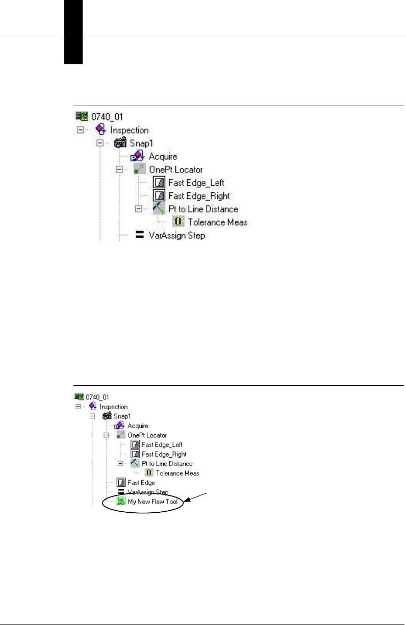
And we run the following code:
Dim onept As Step, snap As Step, newstep as step
'find the first Snapshot Step
Set snap = m_Job.Find("Step.Snapshot", FIND_BY_TYPE)
'add a Flaw Tool at the end of the snapshot’s child list
Set newstep = snap.AddStep "Step.FlawTool"
newstep.name = “My New Flaw Tool” ‘change the step name
Now, the Step Tree would look like this:
FIGURE 2–5. Job with Flaw Tool Added
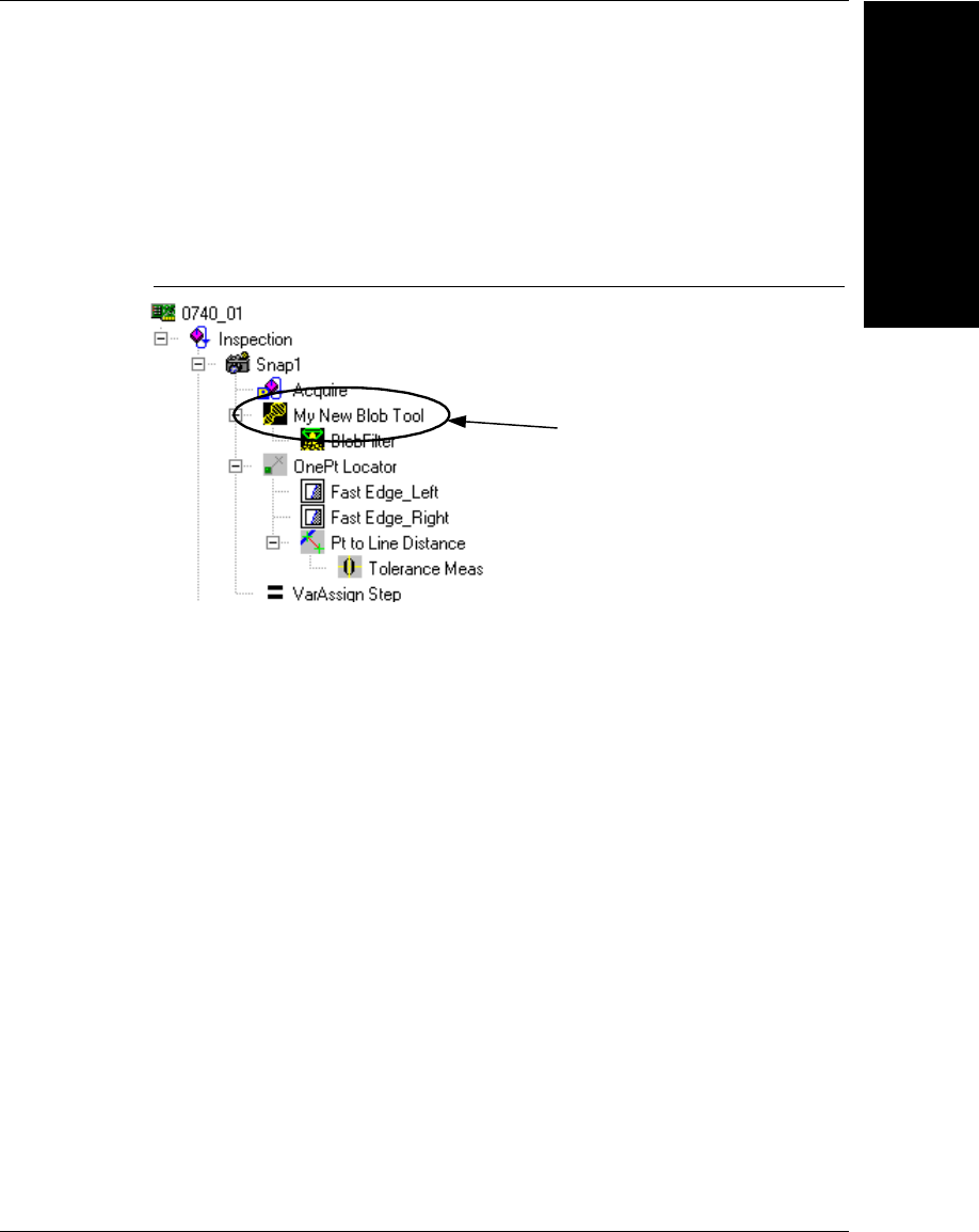
What if you wanted to add a new Blob tool under the Snapshot step, but
we wanted it to be inserted before the One Pt Locator? Then, we could do
the following:
'find the One Pt locator step under the snapshot
Set onept = snap.Find("OnePt Locator", FIND_BY_USERNAME)
‘add a blob tool to the snap, but before the one pt locator
New Step added at
the end of Snap1's
Child list
Steplib and The Step Object
Jobs, Steps and
Datums
2
Visionscape Programmer’s Kit (VSKit) Manual 2-13
Set newstep = snap.AddStep("Step.Blob", S_POSTPROC, _
onept, ADD_BEFORE)
newstep.Name = "My New Blob Tool"
Now, the Step Tree would look like this:
FIGURE 2–6. Job with Blob Tool Added
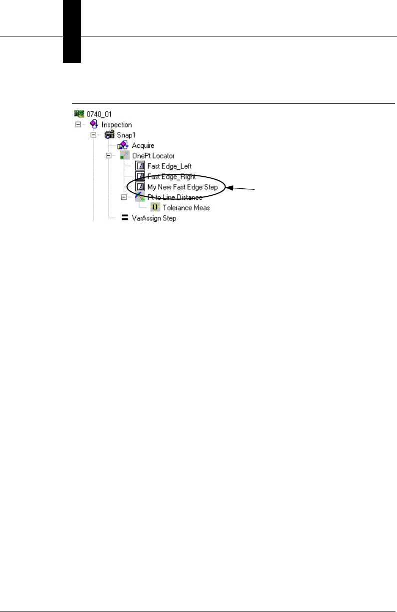
What if we wanted to add a new Fast Edge Step to the OnePt Locator
step, but we wanted it to come immediately after the Fast Edge_Right
Step? Then, we would do the following:
Dim fedge as Step
‘find the Step named “Fast Edge_Right” under onept Step
Set fedge = onept.Find("Fast Edge_Right", FIND_BY_USERNAME)
‘add a new step under onept, after the fedge Step
Set newstep = onept.AddStep("Step.EdgeFast", S_POSTPROC, _
fedge, ADD_AFTER)
newstep.Name = "My New Fast Edge Step"
Now, the Step Tree would look like this:
New Step added
inside Snap1 before
the OnePt Locator
Step
Chapter 2Jobs, Steps and Datums
2-14 Visionscape Programmer’s Kit (VSKit) Manual
FIGURE 2–7. Job with Fast Edge Added
To remove a Step, you use either the Remove or RemoveStep methods.
• Sub Remove(Index As Long)
– index — This is the 1 based index of the Step you wish to remove
from the Step’s collection.
Example:
Continuing the example code from above, if we wanted to remove the
Fast Edge Step we just added, we could simply do this:
onept.remove(3) ‘remove the 3rd child step
If we wanted to remove the Step named “Pt to Line Distance” from
our AddStep example, but didn’t know what its index was, we could
locate it, and then use its index property:
Dim ptlinedist As Step
‘Find the step named “Pt to Line Distance” (under onept)
Set ptlinedist = onept.Find("Pt to Line Distance",_
FIND_BY_USERNAME)
‘use the index from the step itself to remove it
onept.Remove ptlinedist.Index
• Sub RemoveStep(Index As Long, [delChildStep As Long = 1])
– index — This is the 1 based index of the Step you wish to remove
from the Step’s collection.
– delChildStep — Optional.
New Step added
inside OnePt
Locator,
immediately after
the Step named
Fast Edge_Right

Steplib and The Step Object
Jobs, Steps and
Datums
2
Visionscape Programmer’s Kit (VSKit) Manual 2-15
• 1 — (Default) Remove the step from the collection AND
delete it
• 0 — The Step is removed from the collection but is not
deleted
The only difference between Remove and RemoveStep is the optional
delChildStep parameter of RemoveStep. Other than that they are
functionally identical.
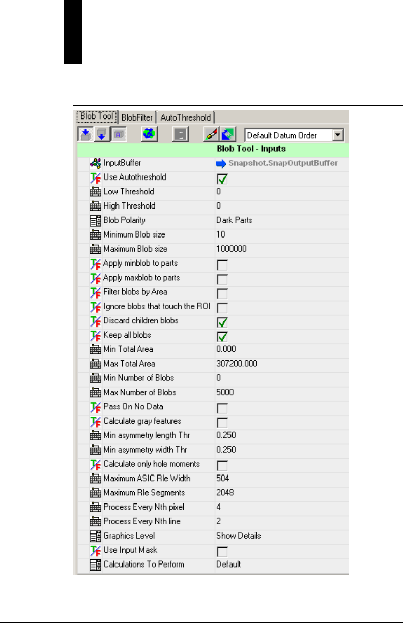
Accessing a Step’s Datum Values
Every Step contains a collection of Datum objects. There is one Datum
object for each of the Step’s parameters, both input and output.
Figure 2–8 shows the Datums for the Blob tool.
Chapter 2Jobs, Steps and Datums
2-16 Visionscape Programmer’s Kit (VSKit) Manual
FIGURE 2–8. Blob Tool Datums

Steplib and The Step Object
Jobs, Steps and
Datums
2
Visionscape Programmer’s Kit (VSKit) Manual 2-17
You can access a Step’s Datums via the following properties:
• Property Datum(symName As String) As Datum
symName: A string that represents the symbolic name of the Datum
you want to access.
You pass the symbolic name of the datum you want to access, and a
reference to the Datum object is returned if found. An exception is
thrown if not found. You can use the StepBrowser utility to look up the
Symbolic Names of every Datum for every Step. You will use this
property when you want to access an individual Datum within a Step.
For more information, see “Using StepBrowser to Look Up Symbolic
Names” on page 2-30.
Example:
In this example, we find a Blob Step, then find its AutoTheshold and
High Threshold Datums, and modify them.
Dim s As Step
Dim datAT As Datum, datHiThresh As Datum
'find a Blob Step
Set s = onept.Find("Step.Blob", FIND_BY_TYPE)
'find the Blob's "Use Autothrehold" datum
Set datAT = s.Datum("UseAutoThr")
'find the Blob's "High Threshold" datum
Set datHiThresh = s.Datum("HiThr")
'turn off AutoThreshold
datAT.Value = False
'set High Threshold to 150
datHiThresh.Value = 150
• Property Datums As AvpCollection
This property returns a reference to the collection of Datum objects
within the Step. You would use this property whenever you want to
iterate through all of a Step’s Datums.
Example:
Dim dm As Datum
‘iterate through all the datums of the step object ‘s’
For Each dm In s.Datums
Debug.Print dm.Name
Next

Chapter 2Jobs, Steps and Datums
2-18 Visionscape Programmer’s Kit (VSKit) Manual
• Property DatumList(cat As EnumAvpDatumCategory)As
AvpCollection
Cat: Specifies a datum category. Available options are:
– D_INPUT: Return only input datums
– D_OUTPUT: Return only output datums
– D_RESOURCE: Return only Resource datums
– D_ALL: Return all datums
This property allows you to specify a Datum category, and it will then
only return a collection of the Datums that are within that category.
Generally, you would use this property in instances where you wanted
to analyze only a Step’s Output or Input Datums.
Example:
Dim colOutputDatums As AvpCollection
Dim dm As Datum
'get a list of only output datums
Set colOutputDatums = s.DatumList(D_OUTPUT)
'loop through the collection
For Each dm In colOutputDatums
Debug.Print dm.Name
Next
Modifying Datum Values
The Datum object has a value property that you use to both get and set its
value. The value property will return a Variant. The Variant is used
because it can hold any kind of data, and the Datum object needs to wrap
many different data types, such as integers, floating point values, strings,
and also array data like points, lines, etc.
Example of getting a Blob tool’s High Threshold value:
‘assume s is a reference to a Blob Step
Dim dat as Datum, vData as Variant
‘get the blob’s High Threshold datum
Set dat = s.Datum("HiThr")
‘the value is scalar, so we can dump it easily
vData = dat.value
Debug.Print “High Threshold Value = “ and vData

Steplib and The Step Object
Jobs, Steps and
Datums
2
Visionscape Programmer’s Kit (VSKit) Manual 2-19
Example of getting the ROI datum:
'get the ROI datum
Set dat = s.Datum("ROI")
'the value property returns an Array in this case
vData = dat.Value
'verify an array was returned
If IsArray(vData) Then
'dump out the ROI parameters
Debug.Print "ROI X = " and vData(0)
Debug.Print "ROI Y = " and vData(1)
Debug.Print "ROI Width = " and vData(2)
Debug.Print "ROI Height = " and vData(3)
Debug.Print "ROI Angle = " and vData(4)
End If
Setting Datum values is just as easy. You simply assign your new value to
the value property.
Example of setting the Blob tool’s High Threshold value:
‘assume s is a reference to a Blob Step
Dim dat as Datum, vData as Variant
‘get the blob’s High Threshold datum
Set dat = s.Datum("HiThr")
‘set High Threshold to 150
dat.value = 150
Example of modifying the Blob tool’s ROI Position:
'get the current ROI data
vData = dat.Value
'move and resize the ROI...
vData(0) = vData(0) + 20 ‘center x
vData(1) = vData(1) – 50 ‘center y
vData(2) = 140 ‘width
vData(3) = 100 ‘height
'now set it back into the Datum
dat.Value = vData
In the above example, we moved the Blob’s ROI 20 pixels to the right and
50 pixels up, and we set the width to 140 and the height to 100 pixels. The
easiest way to modify a Datum that takes an array is to get its current
value, modify it, and set it back into the value property. This insures that
the dimensions of your array will be correct. As mentioned previously, the
Datum object holds many different types of data. You can check the type
Chapter 2Jobs, Steps and Datums
2-20 Visionscape Programmer’s Kit (VSKit) Manual
of any Datum object by querying the read-only Type property. This returns
a string with a similar format to the Step Object’s Type property.
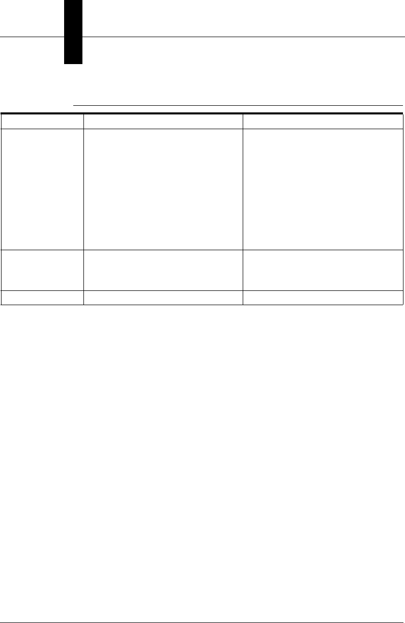
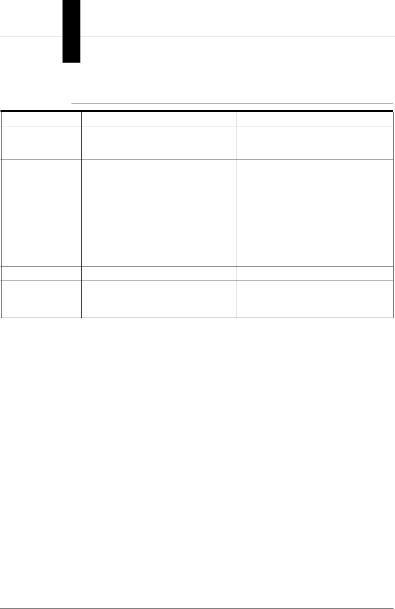
There are many other specialized types of Datums, but those listed in
Table 2–1 are the most common. In Table 2–2, we list each Datum Type,
and the format of the data returned by the value property, as well as the
format expected when you try to set the value property.
TABLE 2–1. Common Datum Types
Data Type Corresponding Datum Type String
Angle Datum.Angle.1
Area Datum.Area.1
Boolean/Status Datum.Status.1
Distance (A Double that can be calibrated) Datum.Distance.1
Enumerated types (Datums displayed in a Combo Box) Datum.Enum.1
Floating Point Datum.Double.1
Integer Datum.Int.1
Line Datum.Line.1
Point Datum.Point.1
ROI (region of interest) Shape.Rect.1
String Datum.String.1

Steplib and The Step Object
Jobs, Steps and
Datums
2
Visionscape Programmer’s Kit (VSKit) Manual 2-21
TABLE 2–2. Datum Types, Get Values, and Set Values
Datum Type Get Value Returns Set Value Returns
Datum.Angle Double Double, Long, or Integer
Datum.Area Double Double, Long, or Integer
Datum.Blob Variant array of requested features for
this blob. The returned array is of size
(x), where x is the number of features
requested. This is based on the value set
in the “Calculations to Perform” Datum in
your Blob tool. The possible values are:
Default - Xcent, Ycent, Area, Color.
Basic - Default results plus Angle,
Nholes, Xmin, YatXmin, Xmax,
YatXMax, YatYmin, Ymin, XatYmax,
Ymax, Xdiff, Ydiff, Major, Minor,
Arearatio, Minora, Minorb, Minorc,
Majora, Majorb, Majorc.
Area - Basic results plus Totarea,
Holearea, Holeratio, Boxarea,
Boxarearatio, Axratio.
All - Area results plus PEround, Length,
Width, Lenratio, Avgrad, Rmin, Rmax,
Radratio, Rminang, Rmaxang, X3sign,
Y3sign, Perimeter, Ppda, Rminx, Rminy,
Rmaxx, Rmaxy.
Set no supported
Datum.BlobTree Variant array of requested features for a
specific blob or all blobs. The returned
array is of size (n,x), where n is the index
of the blob, and x is the index of the
feature requested. Refer to Datum.Blob
for definition of each possible feature.
Set not supported

Chapter 2Jobs, Steps and Datums
2-22 Visionscape Programmer’s Kit (VSKit) Manual
Datum.CalResult Double array of size (3, 16).
Contains both the forward and inverse
linear transforms used for calibration as
well as the calibration stats.
(0,0) = Angle of cal target
(0,1) (0,2) (0,3)
(1,1) (1,2) (1,3)
(2,1) (1,2) (2,3) = forward matrix
(0,4) (0,5) (0,6)
(1,4) (1,5) (1,6)
(2,4) (1,5) (2,6) = inverse matrix
(0,7) = Max Cal Residue
(0,8) = Avg Cal Residue
(0,9) = Pixels per unit X
(0,10) = Pixels per unit Y
(0,11) = Units per Pixel X
(0,12) = Units per Pixel Y
(0,13) = Camera angle
(0,14) = Pix perspective error
(0,15) = World perspective error
Double array of size (3,17).
Array contents are the same as for Get
Value. The 17th element should be set to
0.0.
Datum.CompList Array of handles and names for all items
in the list. Each item could be a Step or a
Datum. Array is (x,2), where x is number
of entries in the list.
(x,0) = Handle to a Step. If the item in the
list is a Step, the handle belongs to the
Step. If the item is a Datum, the handle is
to the owning Step of the datum.
(x,1) = Symbolic name of the Step or
Datum.
(x,2) array where x is the number of
entries in this list
(x,0) = Either the handle of the item (Step
or Datum) or its complete symbolic name
path (Step or Step.Datum) unique to the
Datum.CompList search root (set by the
owner of the datum)
(x,1) = True or False to Add or Remove
the entry from the list.
Datum.DblDmList Array of double values Set not supported
Datum.DblList Array of double values Array of double values
Datum.Distance Double Double
TABLE 2–2. Datum Types, Get Values, and Set Values (continued)
Datum Type Get Value Returns Set Value Returns

Steplib and The Step Object
Jobs, Steps and
Datums
2
Visionscape Programmer’s Kit (VSKit) Manual 2-23
Datum.DMRResult
s
Array sized (n, 38), where n is the
number of Matrices found + 1.
The first row of the array is always
populated with text labels that identify the
data in each column, the actual matrix
data then follows in each successive
row.
(n,0) = Decoded String
(n,1) = Decoded? (boolean)
(n,2) = Linked (boolean)
(n,3) = found symbol type (int)
(n,4) = num rows
(n,5) = num cols
(n,6) = ecc type
(n,7) = format ID
(n,8) = crc expected
(n,9) = crc actual
(n,10) = matrix angle
(n,11) = error code
(n,12) = total num linked
(n,13) = Linked Position
(n,14) = Pixels per Cell
(n,15) = Symbol Height
(n,16) = Symbol Width
(n,17) = X1
(n,18) = Y1
(n,19) = X2
(n,20) = Y2
(n,21) = X3
(n,22) = Y3
(n,23) = X4
(n,24) = Y4
(n,25) = Locate Time
(n,26) = Extent Time
(n,27) = Size Time
(n,28) = Warp Time
(n,29) = Sample Time
(n,30) = Decode Time
(n,31) = Contrast
(n,32) = Error Bits
(n,33) = Damage %
(n,34) = Border Match %
(n,35) = Threshold Value
(n,36) = Symbol Polarity
(n,37) = Img Style
Set not supported
TABLE 2–2. Datum Types, Get Values, and Set Values (continued)
Datum Type Get Value Returns Set Value Returns

Chapter 2Jobs, Steps and Datums
2-24 Visionscape Programmer’s Kit (VSKit) Manual
Datum.Double Double Double, Long, or Integer
Datum.Enum Array containing the current selection in
the first item (long) and the set of
available selections (string) in the
following items.
Example: The Acquire Step's
“CameraNumber” Datum, in which
“Camera 2” was selected, would return
an array that looks like this:
(0) = 1 '0 based index of cur sel
(1) = “Camera 1”
(2) = “Camera 2”
(3) = “Camera 3”
(4) = “Camera 4”
Long/Integer value containing index of
current selection or the string identifying
the new selection
Example: To change the CameraNumber
selection to Camera 3, you could say:
.value = 2 'select 3rd item
OR
.value = “Camera 3”.
Datum.Expression Via the generic Datum interface, the
Value property returns a Double that
contains the last value of the evaluated
expression.
In order to retrieve the expression itself.
You must use the ExpressionDm:
Dim expr as ExpressionDm
Dim strExpr as string
'get Inspection Step's 'criteria for
inspection 'pass datum
Set expr = insp.Datum(“PassCrit”)
strExpr = expr.Expression
String value that contains the new
expression.
Datum.FileSpec String array containing a list of file
names, or if the list is < 1, a single string
variant.
String value containing a file name or
wildcard, or an array of strings containing
files to add to the list. The value(s) you
send are always added to the list, they
do not replace the current list. To clear
the list, pass an empty string ("").
TABLE 2–2. Datum Types, Get Values, and Set Values (continued)
Datum Type Get Value Returns Set Value Returns

Steplib and The Step Object
Jobs, Steps and
Datums
2
Visionscape Programmer’s Kit (VSKit) Manual 2-25
Datum.FlexArray Array sized (x,4) where x is the number
of datums stored in the FlexArray plus 1.
(0,0) contains the number of pages
stored for each datum. Each of the
remaining rows correspond to one
variable: (x,0) is the handle of the datum,
(x,1) is the symbolic name, (x,2) is the
user name, and (x,3) is the category of
the datum (output or resource).
Array sized (x,2) where x is the number
of datums stored in the FlexArray plus 1.
(0,0) contains the number of pages
stored for each datum. Each of the
remaining rows correspond to one
variable: (x,0) is the handle of the datum
and (x,1) is a boolean indicating Add or
Remove.
Datum.InspectionR
esults
Array sized (x,3) where x is the number
of ALL possible results, not just those
selected for upload.
(x,0) = Handle of the Datum that is
available for upload (not the Step)
(x,1) = Symbolic Name of the datum.
(x,2) = True if the datum is to be
uploaded, False if not.
To determine which results are selected
for upload, you must iterate through the
array, checking for those entries where
(x,2) = True.
Array sized (x,3). Where x is the number
of results you are adding to the upload
list. The contents are different then for
Get:
(x,0) = Handle of the Step
(x,1) = Symbolic Name of the Datum
(x,2) = True if you want to upload this
datum, False if you are removing it from
upload list.
Datum.Int Long Long/Integer
Datum.IOList Long, where upper word is the IO Type,
Lower word is the 0 based IO index.
Constants for the various IO types are:
PHYSICAL = 1
VIRTUAL = 2
SENSOR = 3
STROBE = 4
ANALOGOUT = 5
SLAVESENSOR = 6
SERIAL TRIGGER = 11
Note: These values are also represented
by the enumerated type AvpIOType,
which is a member of AvpIOLib.dll.
Two options:
1) Long, where upper word is IO type,
lower word is index.
NOTE: When setting a Serial Trigger,
you will also need to specify the Trigger
string. Use the IoListDm object, and call
the SetTriggerString() method.
Dim trig as IoListDm
Set Trig =
acqstep.Datum("Trigger")
' use serial trigger, 2nd 'port
Trig.value =(11 * andH10000)+1
Trig.SetTriggerString("123")
2) String that lists type and index.
Supported only for sensor, physical and
virtual IO. Format for each is:
“Trigger 1”
“Digital IO 3”
“Virtual IO 22”
TABLE 2–2. Datum Types, Get Values, and Set Values (continued)
Datum Type Get Value Returns Set Value Returns
Chapter 2Jobs, Steps and Datums
2-26 Visionscape Programmer’s Kit (VSKit) Manual
Datum.LayoutInfo Array sized (x, 6) where x is the number
of symbols in the layout, (x, 0) = symbol
ID
(x, 1) = x location of the symbol
(x, 2) = y location of the symbol
(x, 3) = correlation score for the symbol
that was calculated when the layout was
trained
(x, 4) = width of the symbol in pixels
(x, 5) = height of the symbol in pixels.
Same format as Get Value. The input
data replaces the current LayoutData.
For complete information, refer to
Appendix C.
Datum.Line Array of Doubles containing A,B,C.
This is from the line equation
Ax + By + C = 0
Array of Doubles containing A,B,C.
Datum.Matrix Array of Doubles sized (x,y) Array of Doubles sized (x,y)
TABLE 2–2. Datum Types, Get Values, and Set Values (continued)
Datum Type Get Value Returns Set Value Returns

Steplib and The Step Object
Jobs, Steps and
Datums
2
Visionscape Programmer’s Kit (VSKit) Manual 2-27
Datum.OCVResult
s
Array of inspection result data sized (x,
18), where x is the number of symbols in
the layout + 1. The first row of data
contains text labels that identify the
contents of each column. The actual data
for each symbol starts in the 2nd row:
(x, 0)-Passfail-Whether the symbol
passed or failed the inspection
(x, 1)-X location
(x, 2)-Y location
(x, 3)-X offset from the trained position
(x, 4)-Y offset from the trained position
(x, 5)-Correlation score
(x, 6)-Sharpness value calculated
(x, 7)-Sharpness value as a percentage
of the trained sharpness value
(x, 8)-Contrast value calculated
(x, 9)-Contrast value as a percentage of
the trained contrast value
(x, 10)-Number of breaks found
(x, 11)-Initial residue value
(x, 12)-Initial residue value as a
percentage of the symbol's trained area
(x, 13)-Final residue value
(x, 14)-Final residue value as a
percentage of the symbol's trained area
(x, 15)-The area of the largest blob found
in the residue image
(x, 16)-The area of the largest blob as a
percentage of the symbol's trained area
(x, 17)-The trained area
Set not supported
Datum.Point Array of four floats.
(0) = x
(1) = y
(2) = Angle in radians
(3) = scale
Note: Most tools will return data for just
the X and Y values, and the angle and
scale will default to 0 and 1 respectively.
Array of either 2 floats or 4 floats. Specify
just X,Y if you want, or specify all 4
values. Format of the array should be the
same as for Get Value.
Datum.PtList Array of double point values (x,2) where
x is the number of points, (x,0) is the
point-x value, and (x,1) is the point-y
value.
Array of double point values (x,2) where
x is the number of points, (x,0) is the
point-x value, and (x,1) is the point-y
value.
TABLE 2–2. Datum Types, Get Values, and Set Values (continued)
Datum Type Get Value Returns Set Value Returns
Chapter 2Jobs, Steps and Datums
2-28 Visionscape Programmer’s Kit (VSKit) Manual
Datum.Rect Array of four Floats containing left, top,
right, and bottom values.
Array of four Floats/Double/Long/Integer
values containing left, top, right, and
bottom values.
Datum.Statistics Single dimensional array with the
following members:
0 - Owner Step Status (pass/fail)
1 - Measured value
2 - Nominal value
3 - Minimum value
4 - Average value
5 - Maximum value
6 - Standard Deviation
7 - Count
Single dimensional array with the
following members:
0 - Owner Step Status (pass/fail)
1 - Measured value
2 - Nominal value
3 - Minimum value
4 - Average value
5 - Maximum value
6 - Standard Deviation
7 - Count
Datum.Status Boolean Boolean
Datum.Strelem Array of size (x,y) containing a set of
Boolean values.
Array of size (x,y) containing a set of
Boolean values.
Datum.String String String
TABLE 2–2. Datum Types, Get Values, and Set Values (continued)
Datum Type Get Value Returns Set Value Returns

Steplib and The Step Object
Jobs, Steps and
Datums
2
Visionscape Programmer’s Kit (VSKit) Manual 2-29
Datum.Struct Array sized (x,2) where x is the number
of datum elements in the struct. (x,0) is
the error code associated with datum x.
(x,1) contains the data from datum x and
can be of any type.
Array sized (x,2) where x is the number
of datums elements in the struct. (x,0) is
the handle of the datum and (x,1) is a
boolean indicating Add or Remove.
Datum.VerifyResult
s
A 1 dimensional array, the contents of
which depends upon the type of
Verification you have chosen in the DMR
Step's “Print Verification” datum. Refer to
Appendix C for details.
Set not supported
Shape.Rect (ROI) Variant Array of 13 items
(0) = center X
(1) = center Y
(2) = width
(3) = height
(4) = angle (in radians)
(5) = Pt1 X (top-left pt)
(6) = Pt1 Y (top-left pt)
(7) = Pt2 X (top-right)
(8) = Pt2 Y (top-right)
(9) = Pt3 X (bottom-right)
(10) = Pt3 Y (bottom-right)
(11) = Pt4 X (bottom-left)
(12) = Pt4 Y (bottom-left)
Note: 5-12 are expressed as offsets from
the ROI's anchor point.
Variant Array of 5 OR 13 items
Array elements are the same as those
listed to the left.
You can pass a 5 element array if you
just want to modify the location, width,
height and angle
The full 13 element array is only required
in the rare instances when you want to
modify the control points as well
Although index 4 in the array takes an
Angle, many Steps in Visionscape
cannot be rotated. So, those Steps will
ignore any angle you pass in.
Shape.Rhombus Array of (4,2) double values containing
the four points that describe the
rhombus. (x,0) is the point-x and (x,1) is
the point-y.
Array of (4,2) double values containing
the four points that describe the
rhombus. (x,0) is the point-x and (x,1) is
the point-y.
TABLE 2–2. Datum Types, Get Values, and Set Values (continued)
Datum Type Get Value Returns Set Value Returns
Chapter 2Jobs, Steps and Datums
2-30 Visionscape Programmer’s Kit (VSKit) Manual
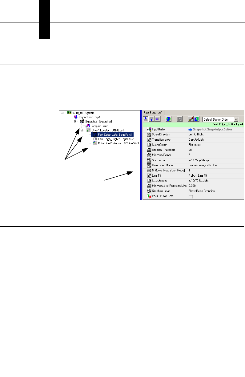
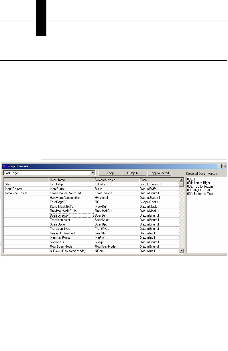
Using StepBrowser to Look Up Symbolic Names
The StepBrowser utility is very useful for looking up information on the
various Steps available in Visionscape. Specifically, it allows you to select
a type of step from a drop-down list, and then see the string that
represents its Step.type, its symbolic name, and most importantly, a list of
all of its Datums, listing the standard name, symbolic name and datum
type of each. StepBrowser is not installed with the standard Visionscape
installation, it is installed with the “Programming Samples and
Programming Manuals”. Once installed, StepBrowser can be found in
Start > Programs > Microscan Visionscape > VSKit > Visionscape Step
Browser.
Once launched, StepBrowser looks like this:
FIGURE 2–9. StepBrowser
Using the combo box at the top left of the window, you can select any type
of Visionscape Step. In the example in Figure 2–9, we've selected the
Fast Edge Step. Once selected, StepBrowser shows you the default user
name, the symbolic name, and the type in the first row of the grid for the
selected Step. All subsequent rows contain a list of every Datum for the
selected Step. This list also provides the default user name, symbolic
name and Datum Type for each. This information is very useful when you
are writing code to find and/or modify the values of many different Datums
in many different Steps.

The JobStep Object
Jobs, Steps and
Datums
2
Visionscape Programmer’s Kit (VSKit) Manual 2-31
The JobStep Object
Up to now, we have only talked about the generic Step object. You should
understand that there are specialized Step types for most of the major
Steps, like the InspectionStep object, SnapshotStep, and
VisionSystemStep. All of these types are derived from the generic Step
object and, therefore, all of these types contain all of the properties and
methods of the Step object. Most of the specialized types don't add any
significant functionality. For example, the InspectionStep object doesn’t
add anything significant to the standard Step interface and, therefore,
there is no reason to use it. In most cases, you will simply use a reference
to a Step object when trying to access the Steps in your Job. The JobStep
and the VisionSystemStep are exceptions to this rule, however. These
objects provide important behavior that goes beyond the standard Step
interface. In this section, we will cover the properties and methods
provided by JobStep, refer to the next section for coverage of the
VisionSystemStep.
As our previous examples have already demonstrated, the JobStep loads
an AVP file, or “Job” from disk. The JobStep can also save the Job after
you have modified it, and it also provides some useful utility functions:
• Sub Load(fileName As String)
– filename — A string that specifies the path to the AVP file you
wish to load. All of the VisionSystemSteps in the specified AVP
will be added to this JobStep. So, if you already have an AVP file
loaded, and you now want to replace that AVP with a new one,
you must remember to delete all the existing VisionSystemSteps
in your Job (using the Remove method) before calling Load.
'keep removing VisionSystemSteps until all are gone
While m_Job.Count > 0
m_Job.Remove 1
Wend
'now load the avp file
m_Job.Load strAvpPath
• Function LoadInspection(pSystem As VisionSystemStep, fileName
As String, [replaceObj As InspectionStep]) As InspectionStep
– pSystem — The VisionSystemStep into which the Inspection
should be loaded

Chapter 2Jobs, Steps and Datums
2-32 Visionscape Programmer’s Kit (VSKit) Manual
– filename — The file path to the InspectionStep AVP file.
– replaceObj — Optional. A reference to an existing InspectionStep
that should be replaced by this inspection.
Loads an InspectionStep AVP file into the given VisionSystemStep.
Optionally, you can specify an existing InspectionStep that you want
to replace with the newly loaded InspectionStep. This method returns
a reference to the newly loaded InspectionStep.
• Sub SaveAll(fileName As String)
Saves an AVP Job to disk at fileName, saving all Vision Systems in
one file.
• Sub SaveSystem(fileName As String, [whichSystem As
VisionSystemStep])
Saves a particular Vision System to the file specified by fileName.
• Sub SaveInspection(pInsp As InspectionStep, fileName As String)
Saves a given InspectionStep to disk at filename
• Function HandleToComposite(hnd As Long) As Composite
Converts a Datum handle or Step handle into an actual Datum object
or Step object. The function returns a reference to a Composite
object, which is the base class for both Step and Datum objects.
Typically, the Setup Manager, Job Manager and Runtime Manager
controls deal with Step and Datum handles, rather than actual Step
and Datum objects. This very useful utility function can be used to
convert those handles into actual objects when needed.
• Function AVPFileInfoGet(fileName As String)
Pass this function the name of an AVP file, and it will read the header
of that file, and return you an 8 element variant array with the
following information:
The first 2 elements provide information on the version of
Visionscape that this AVP was saved under. Typically, a Visionscape
version would be presented as such: 3.6.0 build 91.

The JobStep Object
Jobs, Steps and
Datums
2
Visionscape Programmer’s Kit (VSKit) Manual 2-33
vInfo(0) = Long. Upper word = minor version number (0 in
example)
Lower word = build number (91 in example
above)
vInfo(1) = Long. Upper word = Major version number (3 in
example)
Lower word = middle version number (6 in
example)
vInfo(2) = Long. Total objects contained in the file.
vInfo(3) = Long. Total size of the file.
vInfo(4) = Long. Total number of Steps in the Job.
vInfo(5) = Long. Total Step size
vInfo(6) = String. Identifies the AVP type. There are 3 possible
values.
– “SYSTEMSTEP” File contains just one VisionSystem Step
– “JOBSTEP” File contains multiple VisionSystem Steps
– “INSPSTEP” File contains a single Inspection Step
vInfo(7) = Long. Digitizer type.
• Property PCPriorityRuntime As EnumPCPriority
This utility function provides an easy way to modify the process
priority of your user interface. Options are:
– PP_CLASS_NORMAL Normal Process Priority
– PP_CLASS_HIGH High Process Priority
– PP_CLASS_REALTIME Realtime Process Priority (Default)
When you are running with Visionscape GigE Cameras, you should
always run your process at Realtime in order to prevent timing spikes.
If, however, you are not concerned about timing spikes, and you
would rather not run your user interface as a Realtime process, then
use this property to lower the process priority to either High or
Normal.
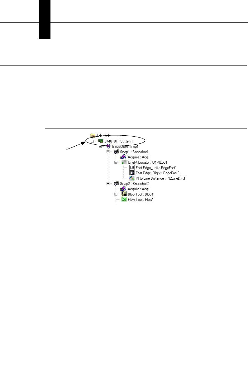
Chapter 2Jobs, Steps and Datums
2-34 Visionscape Programmer’s Kit (VSKit) Manual
The VisionSystemStep Object
Just as the JobStep provides custom functionality on top of the standard
Step properties and methods, so, too, does the VisionSystemStep.
Therefore, you should declare a variable of type VisionSystemStep when
trying to access one:
Dim vs As VisionSystemStep
FIGURE 2–10. VisionSystemStep
The VisionSystemStep represents your Visionscape hardware. When you
load a Job into your JobStep, the immediate children of the JobStep will
always be VisionSystemSteps. A Job constructed in FrontRunner will
always contain one and only one VisionSystemStep. A Job constructed in
AppFactory, or from code, could, however, contain more than one. After
loading a Job, it’s not ready to run until all of the VisionSystemSteps have
been connected to a Visionscape Device (refer to “Visionscape Devices”
on page 1-3 for more information on Devices). The VisionSystemStep
provides special methods that connect to a Visionscape Device, and to
query the current and past Device connection names. A list of these
methods follows.
• Function SelectSystem(systemName As String) As Long
systemName — A string that specifies the name of the Visionscape
device you will be running on.
Refer to “Connecting Jobs to Visionscape Devices” on page 3-6 for
examples of how to use the SelectSystem method. In general, you
are better off using the Download method of the VsDevice object to
connect your hardware, as this works for all devices. However, when
VisionSystem
Step

The VisionSystemStep Object
Jobs, Steps and
Datums
2
Visionscape Programmer’s Kit (VSKit) Manual 2-35
using Visionscape GigE Cameras, you may call SelectSystem
directly if you wish.

Chapter 2Jobs, Steps and Datums
2-36 Visionscape Programmer’s Kit (VSKit) Manual
• Property SelectedVisionSystem As String
This property allows you to query the name of the system/device that
the VisionSystemStep is currently connected to.
• Property SystemLastSavedAs As String
This read-only property returns the name of the Device that was
selected the last time this Job was saved. Typically, you would use
this property to tell your application which Device it should connect to
after you have loaded a Job from disk, since it’s likely that your Job
will always run on the same Device.
Step Object Properties
This section documents all of the properties of the Step Object.
• Property BufferInput As BufferDm
Read-only. Returns the input buffer Datum (if any) in the form of a
BufferDm object.
• Property BufferOutput As BufferDm
Read-only. Returns the output buffer Datum (if any) in the form of a
BufferDm object.
• Property CanRunUntrained As Long
Read-only. Returns True if the Step can run untrained. For example,
the Data Matrix step is a trainable step, but it can run untrained.
• Property Category As EnumAvpStepCategory
Read-only. Returns the category of this Step in relation to its Parent.
• Property Cookie As String
Allows you to attach custom string data to a Step. This data is not
saved with the Step when you save your Job to disk. Use the Tag
property if you need your string to be saved to disk.
• Property Count As Long
Returns the number of child steps under this step.

Step Object Properties
Jobs, Steps and
Datums
2
Visionscape Programmer’s Kit (VSKit) Manual 2-37
• Property Datum(symName As String) As Datum
Read-only. Returns the Datum with the specified symbolic name. An
exception will be thrown if the name is invalid.
• Property DatumList(cat As EnumAvpDatumCategory) As
IAvpCollection
Read-only. Returns the list of Datums for this Step for a specific
category.
• Property Datums As IAvpCollection
Read-only. Returns the list of all Datums for this Step. Refer to
“Accessing a Step’s Datum Values” on page 2-15 for more
information on the Datum, DatumList and Datums properties.
• Property Editability As EnumEditabilityFlags
Returns/sets the Editability Flags. You can combine the available
options to get/set how the Step is handled in the Setup environment.
This property is available for both the Step and Datum objects. Not all
of the available flags apply to the Step object; the following are those
that do:
– EF_CANMASK — Step can be masked
– EF_CANROTATE — Step is rotatable
• Property Handle As Long
Read-only. Returns the Handle of the Step. This is important because
many of the Visionscape Components (Runtime Manager, Setup
Manager…) work with Step handles, rather than references to Step
objects.
• Property HardwareDatum As Composite
Read-only. Returns the VisionDescDm from the VisionSystemStep
that represents the hardware.
• Property Index As Long
Read-only. Returns the index of this Step in the collection of its
Parent.

Chapter 2Jobs, Steps and Datums
2-38 Visionscape Programmer’s Kit (VSKit) Manual
• Property LastError As Long
Read-only. Returns the error code from the last time the Step ran.
This will be 0 when there is no error.
• Property Name As String
Returns/sets the Name of the Step. This is also referred to as the
user name, as the user is free to change this name at will.
• Property NameSym As String
Read-only. Returns the symbolic name of this Step. This name is
assigned by the Visionscape Framework when the Step is created,
and it will never change.
• Property Next As Step
Read-only. Returns the next sibling in the currently selected Step
category.
• Property Parent As Composite
Read-only. Returns the Parent of this Step. Returns a Composite, but
understand that this can be assigned to a Step object, as Composite
is the base class of the Step and Datum classes.
• Property ParentInspection As Composite
Read-only. Returns the parent Inspection Step of this Step.
• Property ParentVisionSystem As Composite
Read-only. Returns the parent VisionSystem Step of this Step.
• Property Prev As Step
Read-only. Member of STEPLIBLib.Step. Returns the previous sibling
in the current Step category.
• Property Rotatable As Long
Read-only. Returns True if this Step can be rotated.
• Property Tag As String

Step Object Methods
Jobs, Steps and
Datums
2
Visionscape Programmer’s Kit (VSKit) Manual 2-39
Returns/sets custom string data for this Step. Similar to the Cookie
property, only this data will be saved to disk with the Step when you
save your Job.
• Property Trainable As Long
Read-only. Returns True if the Step is trainable.
• Property Trained As Long
Read-only. Returns True if the Step has been trained.
• Property TrainInfo As String
Read-only. Gets train information for this step.
• Property Type As String
Read-only. Returns the Type of Step. This will be in the form
“Step.type.1”. Examples:
– Inspection step — “Step.Inspection.1”
– Snapshot step — “Step.Snapshot.1”
– Fast Edge Step — “Step.Edgefast.1”
• Property Untrainable As Long
Read-only. Returns True if the Step is untrainable.
Step Object Methods
This section documents all of the methods of the Step Object:
• Function AddStep(stepOrType, [whichCategory As
EnumAvpStepCategory = S_POSTPROC], [relative As Step], [option
As EAvpCAddOption]) As Step
Adds step to this step in a specific category and optionally in a
specific order in the tree. Refer to “Adding and Removing Steps” on
page 2-10 for a more detailed description.
• Sub ApplyChanges([doingPaste As Boolean = False])

Chapter 2Jobs, Steps and Datums
2-40 Visionscape Programmer’s Kit (VSKit) Manual
Call to apply the set of changed data to the Step. When you are
modifying a Step’s Datum values from code, it’s a good idea to call
this method after you are done. This method tells the Step that it's
datums have been changed, and it should update it's internal data
accordingly.
• Function CanBeContainedBy(Step As Step) As Long
Returns True if the Step can be contained by another specific Step.
• Function CanContain(Step As Step) As Long
Returns True if the Step can contain another specific Step.
• Function ChildCount(Category As EnumAvpStepCategory) As Long
Returns count of children in a specific category.
• Function Find(nameOrType As String, option As
EnumAvpFindOption, [whichCategory As EnumAvpStepCategory =
S_ALL]) As Composite
Finds and returns one object by user name, symbolic name, or type,
optionally in a particular child step category. Please refer to “Finding
Steps in the Step Tree” on page 2-8 for a more detailed description.
• Function FindByType(stepType As String, [findInAllChildren As Long
= 1]) As IAvpCollection
Returns an AvpCollection of all children that match the given type.
Please refer to “Finding Steps in the Step Tree” on page 2-8 for a
more detailed description.
• Function FindParent(stepType As String) As Composite
Finds the Parent Step that matches the specified type. The stepType
parameter is in the form “Step.Type”. Please refer to “Finding Steps in
the Step Tree” on page 2-8 for a more detailed description.
• Function FirstChild(Category As EnumAvpStepCategory) As Step
Returns first child Step in a given category.
• Function GetChildList(cat As EnumAvpStepCategory) As
IAvpCollection

Step Object Methods
Jobs, Steps and
Datums
2
Visionscape Programmer’s Kit (VSKit) Manual 2-41
Creates an AvpCollection for the set of children steps in the specified
category.
• Function IsTimingEnabled() As Long
Returns True if timing is enabled.

Chapter 2Jobs, Steps and Datums
2-42 Visionscape Programmer’s Kit (VSKit) Manual
• Sub Remove(Index As Long)
Removes the child Step at the specified index from this Steps
collection. The removed Step is always deleted. Please refer to
“Adding and Removing Steps” on page 2-10 for more information.
• Sub RemoveStep(Index As Long, [delChildStep As Long = 1])
Removes a Step from the set of children, optionally delete it. Please
refer to “Adding and Removing Steps” on page 2-10 for more
information.
• Function RunWithPreRun(pChangedDatum As Datum) As Long
PreRun, UIAction, then Runs the step, returns True if step executed
(not necessarily passed). Typically, you would call this method when
you have changed a datum value, and then want to run the Step to
see the effect. Pass in a reference to the modified datum, or pass in
Nothing if you simply want to run the Step.
• Function TagForUpload(datumName As String, [bAdd As Long = 1])
As Long
Either adds or removes the specified datum to/from the Inspection’s
“Results to Upload” list. Default behavior is to Add the datum to the
list, if the bAdd parameter is 0, the datum is removed from the list.
• Function Train() As Long
Trains the step, returns True if passed.
• Sub UIAction_Apply(pChangedDatum As Datum)
Sends UIAction 'Apply' notification to the step for the given datum.
• Function Untrain() As Long
Untrains the step.

Datum Object Properties
Jobs, Steps and
Datums
2
Visionscape Programmer’s Kit (VSKit) Manual 2-43
Datum Object Properties
This section documents all of the properties of the Datum Object:
• Property Category As EnumAvpDatumCategory
Read-only. Returns the category of this Datum. Typically, this is used
to check whether a datum is an output or input datum. Categories are
defined by the EnumAvpDatumCategory constants.
– D_All — Signifies all datum types.
– D_INPUT — An input datum that references another datum.
– D_OUTPUT — Indicates an output datum.
– D_PRIVATE — Indicates a private datum.
– D_RESOURCE — An input datum that requires user input to
provide the value.
• Property Cookie As String
Allows you to store custom string data in this datum. This data will
NOT be saved to disk. Use the Tag property if you want to save
custom data along with the datum or Step.
• Property Editability As EnumEditabilityFlags
You will query the bits of this property to determine the editability
settings for the datum. The values defined by EnumEditabilityFlags
indicate the meaning of each bit. The following options are available
for datums:
– EF_ALWAYSUPLOAD — When set, this datum’s value will
always be included in the list of uploaded results.
– EF_CAN_MODIFY_AT_RUNTIME — When set, this flag
indicates that this datum can be modified at runtime. YOU
SHOULD NEVER CHANGE THE STATE OF THIS FLAG.
– EF_ASK_MODIFY_AT_RUNTIME — When set, this flag
indicates that the datum will ask its parent if its OK to modify its
value at runtime. YOU SHOULD NEVER CHANGE THE STATE
OF THIS FLAG.

Chapter 2Jobs, Steps and Datums
2-44 Visionscape Programmer’s Kit (VSKit) Manual
–EF_CANMOVE
EF_CANROTATE
EF_CANSCALE
EF_CANSIZE
EF_CANSTRETCH
These options all apply to shapes only (e.g. the ROI), and
indicate whether the shape can be moved, rotated, scaled, sized
or stretched. YOU SHOULD NEVER CHANGE THE STATE OF
THIS FLAG.
– EF_ENABLEREFEDIT — Indicates that this datum uses a
reference editor, and that it’s enabled.
– EF_NOUSERUPLOAD — When set, indicates that the user
cannot select this datum for upload, but it WILL be included
automatically in the list of uploaded results.
– EF_REFDATUM — Indicates that this datum can be set to
reference other datums.
• Property Handle As Long
Read-only. Returns the Handle of the Datum.
• Property IsReference As Long
Read-only. Returns True if the Datum is referencing another Datum.
• Property LastError As Long
Read-only. Returns the error code from the last time the parent step
ran.
• Property Name As String
Member of STEPLIBLib.Datum. Returns/sets the Name of this object.
• Property NameSym As String
Read-only. Member of STEPLIBLib.Datum. Returns the symbolic
name of this object.
• Property NumScalars As Long

Datum Object Properties
Jobs, Steps and
Datums
2
Visionscape Programmer’s Kit (VSKit) Manual 2-45
Read-only. Member of STEPLIBLib.Datum. If Datum holds array data,
returns size of array. Returns 1 for simple types(int, double, string,
etc.).

Chapter 2Jobs, Steps and Datums
2-46 Visionscape Programmer’s Kit (VSKit) Manual
• Property Owner As Composite
Read-only. Member of STEPLIBLib.Datum. Returns the owner of this
object.
• Property Parent As Composite
Read-only. Member of STEPLIBLib.Datum. Returns the Parent of this
object.
• Property ParentInspection As Composite
Read-only. Member of STEPLIBLib.Datum. Returns the parent
Inspection.
• Property ParentVisionSystem As Composite
Read-only. Member of STEPLIBLib.Datum. Returns the parent
VisionSystemStep.
• Property Reference([followRefLinks As Long]) As Datum
Member of STEPLIBLib.Datum. Returns/sets the reference object for
this object (INPUT datums only).
• Property TaggedForUpload As Long
Member of STEPLIBLib.Datum. Returns True if datum is tagged for
upload in Results.
• Property Type As String
Read-only. Member of STEPLIBLib.Datum. Returns the Type of this
object.
• Property Value As Variant
Gets/Sets the value of this datum. Refer to “Modifying Datum Values”
on page 2-18 for a detailed description.
• Property ValueAsString As String
Allows you to get/set the value of the datum as a string. Some of the
complex datum types do not implement this property and may return
an empty string.

Datum Object Methods
Jobs, Steps and
Datums
2
Visionscape Programmer’s Kit (VSKit) Manual 2-47
• Property ValueCalibrated As Variant
Use this property when you want to retrieve a datums value in
calibrated units. The Job must have been calibrated first. If the Job
has not been calibrated, then this property returns the same data as
the Value property.
• Property Visibility As EnumVisiblityFlags
Returns/sets Visibility Flags. Use this datum to hide/show datums.
There are several valid options defined by the EnumVisibilityFlags
type, but the only ones that really matter are those that follow:
– VF_NEVER — The datum is not visible. This means that the
datum will not show up in the Datum page of the Setup Manager
control. When applied to ROIs, this means that the ROI will not
show up in the buffer and, therefore, cannot be moved by the
user.
– VF_ALWAYS — The datum is always visible.
– VF_ADVANCED — The datum is advanced, and will only be
shown in the DatumGrid control if the “Advanced” button on the
toolbar is pressed.
• Property Visible As Long
Returns True if visibility flag of datum is set.
Datum Object Methods
This section documents all of the methods of the Step Object:
• Function FindParent(stepType As String) As Composite
Finds the Parent Step that matches the specified type. The stepType
parameter is in the form “Step.Type”. Please refer to “Finding Steps in
the Step Tree” on page 2-8 for a more detailed description.
• Sub Regen([bDoPicture As Long = 1])
Regenerates the datum, and optionally takes a picture while doing so.
“Regenerate” means to PreRun and then Run every Step that this
datum is dependent upon.

Chapter 2Jobs, Steps and Datums
2-48 Visionscape Programmer’s Kit (VSKit) Manual
• Function TagForUpload([bAdd As Long = 1]) As Long
Add (True) or remove (False) this datum to/from the Inspection's
“Results to Upload” list.
Step Handles: Converting to Step Objects
A Step Handle is a long integer that represents the address in memory (a
pointer) of an underlying Step object that the Visionscape framework
knows how to deal with. Several of the Visionscape components deal
primarily with Step Handles, rather than with Step Objects. Those
components are the Runtime Manager, Setup Manager, Job Manager
and Datum Manager. Each of these components have properties and
methods that take Step Handles as inputs, and that will also return Step
Handles to you. This leads to two questions:
• How do I pass a step handle to a method or property?
The Step Object provides a Handle property, so simply reference this
property whenever you need to pass a Step Handle.
• How do I work with a step handle that is returned to me by a property
or method?
Steplib provides the AvpHandleConverter object that can be used to
convert Step Handles to Step Objects. In the following example, we
demonstrate how the step handle returned by Setup Manager's
GetCurrentStep function could be converted to a Step Object:
Dim hc As New AvpHandleConverter
Dim selStep As Step, hStep As Long
'this function returns a step handle
hStep = ctlSetup.GetCurrentStep
If hStep <> 0 Then
'convert the handle to a Step Object
Set selStep = hc.AvpObject(hStep)
Debug.Print "Selected Step is " and selStep.Name
End If

Visionscape Programmer’s Kit (VSKit) Manual 3-1
3
Talking to Visionscape
Hardware:
3
CHAPTER 3 Talking to Visionscape
Hardware: VsCoordinator
and VsDevice
Introduction to Visionscape Device Objects (VSOBJ.DLL)
In this chapter, we will talk about the Visionscape Device Objects. You will
use these objects to query your PC and/or your network for Visionscape
hardware Devices. These objects live in VSOBJ.dll, so to access them,
add a reference to the following library:
+Visionscape Library: Device Objects
This section introduces important concepts; it’s highly recommended that
you read through it.
VsCoordinator
The primary purpose of the VsCoordinator object is to discover the
available Visionscape hardware that is installed in your PC or connected
to your network (such as smart cameras), and to maintain a list of these
Devices. VsCoordinator has a very special property in that there will only
ever be one instance of this object in a given process (EXE), regardless
of how many times you instantiate the object in your project. For example,
if you declare a new VsCoordinator in two different forms, both will
actually be the same instance of the object. This unusual feature makes it
possible for the VsKit controls to talk to each other almost magically (refer

Chapter 3Talking to Visionscape Hardware: VsCoordinator and VsDevice
3-2 Visionscape Programmer’s Kit (VSKit) Manual
to Chapter 5, “Using VsKit Components” for more information on the VsKit
components). You will most likely use the VsCoordinator object in every
Visionscape user interface you create because, as we said,
VsCoordinator is the object that provides you with access to Visionscape
Devices. You access the available Visionscape hardware via the Devices
collection property of VsCoordinator. Each item in the collection is a
VsDevice object.
VsDevice
The VsDevice object is a programmer’s interface to any Visionscape
device. Its API includes methods to start, stop, upload, download, take
control, query status, and configure a device. It also contains properties
that describe the device, such as the device type (GigE Camera, smart
cameras, etc.), the digitizer type, etc. Therefore, the VsDevice object is
central to writing your own Visionscape UI. You will almost certainly use
the VsDevice and VsCoordinator objects in every project.
VsCoordinator and Device Discovery
When you instantiate a VsCoordinator object for the first time, it will
immediately try to detect all of the Visionscape devices that you have
installed in your PC. This includes any Software Systems that you may
have created. Cameras and Software Systems will always be added to
the Devices collection first. So, after you’ve instantiated a VsCoordinator,
you can immediately iterate through its Devices collection and access
your cameras and Software Systems. The following example iterates
through each device and outputs its name to the debug output window:
' Required Project References:
'+Visionscape Library: Device Objects (vsobj.dll)
Dim coord as VsCoordinator
Dim dev as VsDevice
'instantiate our VsCoordinator
Set coord = new VsCoordinator
'iterate through all devices in the .Devices collection
For each dev in coord.Devices
Debug.Print dev.Name
Next dev
Introduction to Visionscape Device Objects (VSOBJ.DLL)
Talking to Visionscape
Hardware:
3
Visionscape Programmer’s Kit (VSKit) Manual 3-3
To find a particular device in the list by name, you can use the
FindDeviceByName method.
Note: To see the names of Software Systems in your PC, double-click on
the Visionscape Backplane icon in the Windows System Tray. This will
open the AvpBackplane window, which will provide you with a list of all
available Software Systems.
Networked Devices (such as smart cameras) are handled differently,
however. Because they live on the network, they cannot be discovered
immediately. The next section explains how Networked Devices are
discovered.
Networked Device Discovery and UDPInfo
There is a special consideration for devices that are connected via a
network, including the smart cameras. Networked devices periodically
announce their state on the network, allowing them to be monitored to
some extent without requiring a point to point connection. This is
accomplished by broadcasting a short network message approximately
every five seconds. This message is sent using UDP, which is a network
protocol similar to TCP but much lighter weight and without the extensive
error checking. This UDP message, or “packet”, contains identification
and other useful information such as inspection counters and timing data.
Visionscape knows which cameras are on the network by listening on a
network port for these special UDP messages. So, when you instantiate a
VsCoordinator for the first time, like when your application first starts, your
Networked Devices won’t be added to the Devices collection until a UDP
message has been received from each of them. So, it may take up to 10
seconds for them to be discovered. If you have previously instantiated
VsCoordinators in your application, then it’s very likely that all the
Networked Devices will have already been discovered, and already
added to the list. This wait will also not be necessary if the Visionscape
Backplane process is already running (you’ll see the following icon in the
Windows System Tray):
Networked Devices are always added to the end of the Devices collection
when they are discovered. The information in the UDP packet is available

Chapter 3Talking to Visionscape Hardware: VsCoordinator and VsDevice
3-4 Visionscape Programmer’s Kit (VSKit) Manual
to a programmer by accessing the fields of the UDPInfo property of
VsDevice.
Consider the following Visual Basic example, which simply searches
through the Devices collection of VsCoordinator for a network device
called “MyCameraName” and then prints the IP address and inspection
cycle count of the first inspection to the debug window. Notice that the
inspection cycle count is accessed via UDPInfo.
' Required Project References:
'+Visionscape Library: Device Objects (vsobj.dll)
Dim coord as VsCoordinator
Dim dev as VsDevice
'instantiate our VsCoordinator
Set coord = new VsCoordinator
'iterate through all devices in the .Devices collection
For each dev in coord.Devices
If dev.Name = "MyCameraName" then
Debug.Print dev.IPAddress
Debug.Print dev.UDPInfo.CountCycles1
Exit For
End If
Next dev
The previous example did not even require a connection to be made to
obtain the inspection cycle count. This would be an ideal way to report
information about multiple devices on a network at once, and with almost
no overhead. The only caveat is that new info is only received every five
seconds, so by no means is this a real time approach.
Note: The example as shown simply creates a VsCoordinator and then
immediately iterates over the Devices list looking for a particular camera.
But, as we noted previously, this wouldn’t work if this was the first time
you created a VsCoordinator object, as the device “MyCameraName”
would most likely not have been discovered yet. The following section will
describe the recommended strategy for finding and connecting to devices
without being concerned about this potential delay.

Introduction to Visionscape Device Objects (VSOBJ.DLL)
Talking to Visionscape
Hardware:
3
Visionscape Programmer’s Kit (VSKit) Manual 3-5
Device Focus
The term “Focus” in this context is not related to focusing a camera.
Instead, it refers to the idea that, in a typical user interface, each GUI
element is synchronized to reflect the status of a single chosen device.
The device that is the center of attention is referred to as the Focus
Device, and you can configure all of the VsKit controls to automatically
switch to the Focus Device without any user coding. It’s also possible to
have more than one Focus Device in an application, but we will start out
with the assumption that there is just one.
As previously mentioned, there may be a delay before all devices have
been discovered and placed in the Devices list of VsCoordinator. The
following example shows a typical way to select a device the moment it
becomes ready to use. This is done by using the
DeviceFocusSetOnDiscovery method of VsCoordinator.
This time, the VsCoordinator and VsDevice objects are declared
WithEvents. Both objects have many useful events that are used in
practically every application. In Form_Load, the VsCoordinator is created,
and then the method DeviceFocusSetOnDiscovery is called with the
name of the desired smart camera. When the named device is available
and in the Devices list, VsCoordinator raises the OnDeviceFocus event.
At that point, you can access its corresponding VsDevice object.
' Required Project References:
'+Visionscape Library: Device Objects (vsobj.dll)
Dim WithEvents coord As VsCoordinator
Dim WithEvents dev As VsDevice
Private Sub Form_Load()
Set coord = New VsCoordinator
coord.DeviceFocusSetOnDiscovery "MyCameraName"
End Sub
Private Sub Form_Unload(Cancel As Integer)
Set coord = Nothing
Set dev = Nothing
End Sub
Private Sub coord_OnDeviceFocus(ByVal objDevice As VSOBJLib.IVsDevice)
Set dev = objDevice
End Sub

Chapter 3Talking to Visionscape Hardware: VsCoordinator and VsDevice
3-6 Visionscape Programmer’s Kit (VSKit) Manual
Note that this example does not make any sort of connection; it simply
selects a device. If your UI were using the VsRunView control (Chapter
4), this would be the logical time to call its AttachDevice method, which
connects that control to the Device and allows it to begin displaying its
images and results. If your UI were using the VsKit controls (Chapter 5),
many have an AutoConnect property that will automatically create a
connection when the OnDeviceFocus event occurs.
Connecting Jobs to Visionscape Devices
At this point, you should understand that the VsDevice object represents
a piece of Visionscape Hardware, and that the VsCoordinator is intended
to provide you with a list of all available Devices. In the previous chapter,
we explained Jobs and Steps, and how to load AVP files from disk. Once
a Job is loaded, however, you must select the Device that it will run on
before it can actually function. In the following example, we demonstrate
how to use the VisionSystem Step’s SelectSystem method to connect the
VisionSystem Step to the first device in the PC.
Dim m_coord As VsCoordinator
Dim m_dev As VsDevice
Dim m_Job As JobStep
Private Sub Form_Load()
Dim vs As VisionSystemStep
'find our device
Set m_coord = New VsCoordinator
Set m_dev = m_coord.FindDeviceByName("0740_01")
'load our AVP from disk
Set m_Job = New JobStep
m_Job.Load App.Path & "\SampleJob.avp"
'get the first vision system step
Set vs = m_Job(1)
'Connect VisionSystem Step to the Device
vs.SelectSystem m_dev.Name
'because the 0740 is a host board, we are now
'ready to run,so start all inspections running
m_dev.StartInspection 'starts all inspections by default
End Sub
'when running on a Host Board or Software System,
' always stop the inspections before exiting

Connecting Jobs to Visionscape Devices
Talking to Visionscape
Hardware:
3
Visionscape Programmer’s Kit (VSKit) Manual 3-7
Private Sub Form_Unload(Cancel As Integer)
m_dev.StopInspection
End Sub
The previous example loads a Job from disk, selects the hardware, and
starts it running. We also make sure to call StopInspection in the
Form_Unload event to stop all inspections before the application exits.
This is important when running with Software Systems. Your application
may crash if it attempts to shut down while inspections are still running
with a Software System. You do not need to worry about stopping
inspections on exit when dealing with smart cameras. For these devices,
it’s not enough to simply select the hardware; you must also download
your Job to the Device. In that case, the following code could be used.
Assume we want to load a Job onto a smart camera named
“MySmartCam”.
Dim m_coord As VsCoordinator
Dim m_dev As VsDevice
Dim m_Job As JobStep
Private Sub Form_Load()
Dim vs As VisionSystemStep
'find our device
Set m_coord = New VsCoordinator
Set m_dev = m_coord.FindDeviceByName("MySmartCam")
'load our AVP from disk
Set m_Job = New JobStep
m_Job.Load App.Path & "\SampleJob.avp"
'get the first vision system step
Set vs = m_Job(1)
'download the vision system step to the device
m_dev.Download vs
'loop for as long as the transfer is in progress
While m_dev.CheckXferStatus(100) = XFER_IN_PROGRESS
DoEvents ' so VB does not appear to hang
Wend
'ready to run,so start all inspections running
m_dev.StartInspection 'starts all inspections by default
End Sub
If you compare this example to the previous one, you’ll see that the only
difference is that we replaced the call vs.SelectSystem dev.Name with the
code to handle downloading the VisionSystem Step. It’s important to
understand that the second example works for all devices. Although

Chapter 3Talking to Visionscape Hardware: VsCoordinator and VsDevice
3-8 Visionscape Programmer’s Kit (VSKit) Manual
nothing needs to actually be downloaded (since the job is running locally
on the PC), this call:
dev.Download vs
is functionally equivalent to this call:
vs.SelectSystem dev.Name
In other words, the Download method will call the SelectSystem method
for you, so you don’t need to do both.
Note: Thus, if you are trying to write a generic UI that will work with all
Visionscape Devices, we recommend that you use the call to Download
rather than SelectSystem.
Also, you must remember that you need to stop all inspections from
running when you exit your application if you are running a Software
System.
The previous examples showed, with a small amount of code, how to get
a Visionscape Job loaded into memory and running. We haven’t showed
you how to view the images and results yet, that's coming in the next
chapter. But, how about an even easier way to get a Job loaded and
running? Consider this example:
Dim m_coord As VsCoordinator
Dim m_dev As VsDevice
Private Sub Form_Load()
'find our device
Set m_coord = New VsCoordinator
Set m_dev = m_coord.FindDeviceByName("0740_01")
m_dev.DownloadAVP App.Path & "\SampleJob.avp"
While m_dev.CheckXferStatus(100) = XFER_IN_PROGRESS
DoEvents ' so VB does not appear to hang
Wend
m_dev.StartInspection
End Sub
'if running on a Host Board or Software System,
' always stop the inspections before exiting
Private Sub Form_Unload(Cancel As Integer)

What Else Can I Do With Device Objects?
Talking to Visionscape
Hardware:
3
Visionscape Programmer’s Kit (VSKit) Manual 3-9
m_dev.StopInspection
End Sub
In this example, we used the VsDevice object's DownloadAVP method,
and directly specified the AVP file we wanted to load. This handles
loading the AVP for us, and will download the first VisionSystem step in
the Job. This method also works with all Visionscape Devices. With this
method, you don’t need to use the JobStep object at all. If the goal of your
UI is to very simply load an AVP from disk and get it running, the above
sample is the simplest way to do it. If your goal is to write a more complex
UI that provides the user with access to the Steps and Datums of the AVP,
or if you need to scan the Steps of the Job to gather information about it
before you start running, then you will want to load the Job into a JobStep
first, as demonstrated in our previous example.
What Else Can I Do With Device Objects?
Table 3–1 contains example code for common situations. For important
additional details, please refer to the detailed documentation later on in
this chapter.

Chapter 3Talking to Visionscape Hardware: VsCoordinator and VsDevice
3-10 Visionscape Programmer’s Kit (VSKit) Manual
TABLE 3–1. How Do I...
How Do I... Example
Enumerate Devices 1. Declare and create a VsCoordinator
Dim coord as new VsCoordinator
2. Iterate over the Devices collection
Dim dev as new VsDevice
For each dev in coord.Devices
Debug.Print dev.Name
Next dev
Connect to a Smart Camera 1. Declare a VsCoordinator (WithEvents) and VsDevice
Dim WithEvents coord As VsCoordinator
Dim WithEvents dev As VsDevice
2. Create the VsCoordinator
Set coord = New VsCoordinator
3. Use the DeviceFocusSetOnDiscovery method
coord.DeviceFocusSetOnDiscovery "Camera Name"
4. Handle the OnDeviceFocus event and set the VsDevice
Private Sub coord_OnDeviceFocus(ByVal
objDevice As VSOBJLib.IVsDevice)
Set dev = objDevice
End Sub
Control a Device 1. Use the TakeControl method of a connected VsDevice
bGotControl = dev.TakeControl("username", "pwd")
2. Check the return value to see if it succeeded
If bGotControl Then
' now we can start / stop, etc…
End If
Start/Stop Inspections dev.StartInspection ' start all inspections
dev.StartInspection N ' start inspection N
dev.StartInspection N, 2 ' start inspection
N and run for 2 cycles
dev.StopInspection ' stop all inspections
dev.StopInspection N ' stop inspection N

What Else Can I Do With Device Objects?
Talking to Visionscape
Hardware:
3
Visionscape Programmer’s Kit (VSKit) Manual 3-11
Download an AVP file 1. Get a VsDevice reference for the Visionscape
Device you wish to download to.
2. Use the DownloadAVP method of the VsDevice
dev.DownloadAVP "path to avp file"
3. Check the transfer status in a loop while
calling DoEvents to allow other UI events to
continue while waiting for the download to finish
While dev.CheckXferStatus(100)
= XFER_IN_PROGRESS
DoEvents ' so VB does not appear to hang
Wend
4. For more information about downloading a Job,
see “Downloading a Job” on page 3-14
TABLE 3–1. How Do I... (continued)
How Do I... Example

Chapter 3Talking to Visionscape Hardware: VsCoordinator and VsDevice
3-12 Visionscape Programmer’s Kit (VSKit) Manual
Download an already loaded Job 1. Get a VsDevice reference for the Visionscape
Device you wish to download to.
2. Get a reference to the VisionSystem Step in your Job
Dim vs as VisionSystemStep
Set vs = m_Job(1) 'first visionsystem step in the job
3. Use the Download method of VsDevice, and pass it
the VisionSystem Step
dev.Download vs 'reference to VisionSystem Step
4. Check the transfer status in a loop while calling DoEvents
to allow other UI events to continue while waiting for
the download to finish
While dev.CheckXferStatus(100) = XFER_IN_PROGRESS
DoEvents ' so VB does not appear to hang
Wend
5. For more information about downloading a Job,
see “Downloading a Job” on page 3-14
Get information on the running Job 1. Tell Device to update its Namespace information
by calling QueryNamespace.
m_dev.QueryNamespace
2. Reference the NameSpace property, which is
a VsNameNode object with child VsNameNode
objects arranged in a tree structure that is identical
to the Loaded Job.
Dim nnJob as VsNameNode
Set nnJob = m_dev.Namespace
Getting information on a Device's IO
capabilities
1. Tell device to update its IO information by calling
the QueryIOCaps method.
m_dev.QueryIOCaps
2. Access the IOCaps property. This is a VsIOCaps object,
the properties of which describe the IO capabilities of the device.
Dim iocaps as VsIOCaps
Set iocaps = m_dev.IOCaps
Determine a Device's Type 1. Query the DeviceClass property.
2. If you wanted to make sure a VsDevice object was referencing
a smart camera, do the following:
If m_dev.DeviceClass
= DEVCLASS_SMART_CAMERA Then
3. If you wanted to make sure a VsDevice object was referencing
a Host Board…
If m_dev.DeviceClass =
DEVCLASS_HOST_BOARD Then
TABLE 3–1. How Do I... (continued)
How Do I... Example

A Detailed Look at VsDevice
Talking to Visionscape
Hardware:
3
Visionscape Programmer’s Kit (VSKit) Manual 3-13
A Detailed Look at VsDevice
VsDevice is the primary interface when communicating to any
Visionscape device, regardless of the type. In fact, one of the primary
features of this object is to provide a common programming interface,
regardless of whether the target device is a smart camera, a GigE
Camera, or software emulated. You should never create a “new”
VsDevice object; instead, you would retrieve a reference to a VsDevice
through one of the VsCoordinator methods described above.
Device Control Functions
VsDevice provides several methods to control the state of your device:
Taking Control / Releasing Control of a Smart Camera
When dealing with smart cameras, your user interface should “Take
Control” of these devices before you perform any operation that may
affect their behavior. Although it’s not required that you take control of a
device before downloading to it or starting and stopping inspections, we
strongly recommended that you do. This insures that your application
does not conflict with another user on another PC who may currently be
connected to the smart camera (via FrontRunner or AppRunner,
perhaps). The TakeControl method requires a user id and password:
(NOTE: The TakeControl method is relevant only to smart cameras).
Dim bGotControl As Boolean
bGotControl = dev.TakeControl("hawkeye", "vision")
If bGotControl Then
' now we can start / stop, download, etc…
End If
You can also check whether you have control by using the VsDevice
HaveControl property:
If dev.HaveControl Then
' now we can start / stop, etc…
End If
Release Control by using the ReleaseControl method of VsDevice:
dev.ReleaseControl

Chapter 3Talking to Visionscape Hardware: VsCoordinator and VsDevice
3-14 Visionscape Programmer’s Kit (VSKit) Manual
Start / Stop Inspections
It’s easy to start and stop some or all of the inspections on a given
Device. Simply use the StartInspection and StopInspection methods:
dev.StartInspection ' start all inspections
dev.StartInspection N ' where N=0 based index of the inspection
dev.StartInspection N, 2 ' start inspection N and run for 2 cycles
dev.StopInspection ' stop all inspections
dev.StopInspection N ' stop inspection N (0 based index)
Downloading a Job
To download a job file, you can use the DownloadAVP function that takes
the file name of an .AVP file. Although you can do a download
synchronously - a call that would not return until the download is complete
- this is not recommended, as it will hang your application for the duration.
The preferred method is illustrated in the following example:
dev.DownloadAVP "C:/vscape/jobs/myjob.avp"
The second parameter to the DownloadAVP call is left at its default value
of 1, which signifies an asynchronous transfer; a 0 value would download
synchronously (again, this is not recommended). After this call, we need
to wait until the download is finished, but we will allow events in the
meantime.
' hang out here while downloading, but allow events
' allow CheckXferStatus to sleep for 100 ms
While dev.CheckXferStatus(100) = XFER_IN_PROGRESS
DoEvents ' so VB does not appear to hang
Wend
The parameter to CheckXferStatus is the number of milliseconds to sleep
(and, therefore, not tie up CPU resources) while waiting to see if the
download is complete. The possible return values for CheckXferStatus
are:
• XFER_IN_PROGRESS — Still transferring the job
• XFER_DONE — Finished with the transfer
• XFER_ERROR — Transfer was unsuccessful
As the transfer progresses, the OnXferProgress event is raised by the
VsDevice object to report progress messages and state or error

A Detailed Look at VsDevice
Talking to Visionscape
Hardware:
3
Visionscape Programmer’s Kit (VSKit) Manual 3-15
information. You can use this information to either update a progress bar,
or you can simply display the messages for the user:
Private Sub dev_OnXferProgress(ByVal nState As Long, ByVal nStatus As Long, ByVal
msg As String)
' in the middle of a download, display the progress messages
Debug.print msg
End Sub
The parameters passed along with the OnXferProgress event are:
• nState — This Long value represents the overall state of the transfer.
The following values are possible:
– -1 — Transfer error
– 0 — Transfer started
– 1 — Transfer complete
– 3 — Transfer message
• nStatus — Provides data relative to the current nState value. If nState
indicates an error condition, then this Long value holds the error
code. For all other states, nStatus holds a value from 1 to 100 that
indicates the current completion percentage of the download. So, this
value can be used to update a progress bar.
• msg — This string value describes the current status of the download.
You may prefer to simply printout these messages for your user
rather than implementing a progress bar.
Uploading a Job
Using the Upload method of VsDevice is slightly more involved, as we will
be receiving a new VisionSystemStep, and must prepare the job to
receive it. You will get the new VisionSystemStep from the
OnUploadComplete event, as shown in the following example:
' declare a global VisionSystemStep because we will receive this Step
' in an event and need to stash it somewhere
Private m_UploadedVS As VisionSystemStep
' this is the event that will give us the new VisionSystemStep
Private Sub m_device_OnUploadComplete(ByVal nStatus As Long, ByVal pVS As
STEPLIBLib.IVisionSystemStep)
Set m_UploadedVS = pVS

Chapter 3Talking to Visionscape Hardware: VsCoordinator and VsDevice
3-16 Visionscape Programmer’s Kit (VSKit) Manual
End Sub
Private Sub UploadProgram()
' here we get the device from the Coordinator, and
' exit early if there are no inspections or this is
' a host based situation that does not require an upload
Set dev = m_coord.DeviceFocus
If dev Is Nothing Then Exit Sub
If dev.NumInspections = 0 Or dev.IsHostBased Then Exit Sub
If Not dev.ProgramController Is Nothing Then
' first blow away current program
ReleaseProgram
End IF
Dim Job as JobStep
If dev.ProgramController Is Nothing Then
' make a new job if we don't have one already
If m_coord.Job Is Nothing Then
Set Job = New JobStep
m_coord.Job = Job
End If
Set Job = m_coord.Job
dev.Upload Job, vs
While dev.CheckXferStatus(150) = XFER_IN_PROGRESS
DoEvents
Wend
If (dev.CheckXferStatus(0) = XFER_ERROR) Then
MsgBox "Upload failed", vbExclamation,
"File Transfer Error"
Set vs = Nothing
Set m_UploadedVS = Nothing
Else
' we have a successful upload, take the VisionSystemStep
' we received in the OnUploadComplete event
Set vs = m_UploadedVS
Set m_UploadedVS = Nothing
End If
dev.ProgramController = vs
End If
End Sub

Obtaining Device Information
Talking to Visionscape
Hardware:
3
Visionscape Programmer’s Kit (VSKit) Manual 3-17
Obtaining Device Information
VsDevice has many properties and methods that provide valuable
information about the current device.
Basic Device Information
One of the basic uses of VsDevice is to identify the device in question and
gain access to some current information about it. For example, this code
lists basic information about all devices in the VsCoordinator devices list:
Dim dev As VsDevice
For Each dev In coord.Devices
Debug.Print "Name = " & dev.Name
Debug.Print "Class = " & dev.DeviceClass
Debug.Print "Controlled by = " & dev.NameOfController
Debug.Print "Model = " & dev.DeviceModel
Debug.Print "Digitizer = " & dev.DigitizerModel
Debug.Print "IP Address = " & dev.IPAddress
Debug.Print "MAC Address = " & dev.MACAddress
Debug.Print "Software Rev. = " & dev.SoftwareVersion
Debug.Print "# Inspections = " & dev.NumInspections
Debug.Print "# Snaps = " & dev.NumSnapshots(0)
Next dev
DeviceClass Property
The DeviceClass field is a very useful way of determining which type of
device it is; the enumeration is:
Public Enum tagDEVCLASS
DEVCLASS_UNKNOWN=0
DEVCLASS_SOFTWARE_EMULATED=1
DEVCLASS_HOST_BOARD=2
DEVCLASS_PROCESSOR_BOARD=3
DEVCLASS_SMART_CAMERA=4
DEVCLASS_SMART_CAMERA_OLDER=5
DEVCLASS_SMART_CAMERA_UNREACHABLE=6
DEVCLASS_CAMERA=7
End Enum
The most important values are:
• DEVCLASS_SMART_CAMERA — A smart camera, for example.

Chapter 3Talking to Visionscape Hardware: VsCoordinator and VsDevice
3-18 Visionscape Programmer’s Kit (VSKit) Manual
• DEVCLASS_HOST_BOARD — A vision device without a built in CPU
(requiring execution using the PC).
• DEVCLASS_SOFTWARE_EMULATED — A software system with no
hardware.
• DEVCLASS_SMART_CAMERA_UNREACHABLE — A smart
camera that, due to network topology, cannot be connected to via a
TCP connection. Perhaps it’s on a different subnet or has an
incompatible IP address.
• DEVCLASS_PROCESSOR_BOARD — A vision accelerator device
with a built in CPU. Not supported by Visionscape V4.1.0.
IsHostBased Property
You can use the IsHostBased property to determine if there is no target
processor for the device; in other words, if the device is host-based or
softwar-emulated.
Determining if any Inspections are Running
This is easily accomplished via the IsInspectionRunning method.
• Function IsInspectionRunning([nInsp As Long = -1]) As Boolean
nInsp — Optional 0 based index of the inspection. The default is -1,
which means check all inspections to see if ANY are running.
Device States
It’s usually important to know what state a device is in. This information is
obtained via the DeviceState property of VsDevice. The enumeration for
the possible values is:
Public Enum tagDEVSTATE
DEVSTATE_UNKNOWN=0
DEVSTATE_RUNNING=1
DEVSTATE_STOPPED=2
DEVSTATE_NOJOB=3
DEVSTATE_NOCOMM=4
DEVSTATE_ERROR=100
DEVSTATE_FILE_XFER=101
DEVSTATE_TRYOUT=102

Obtaining Device Information
Talking to Visionscape
Hardware:
3
Visionscape Programmer’s Kit (VSKit) Manual 3-19
DEVSTATE_EDIT=103
DEVSTATE_LIVE=104
DEVSTATE_FUNCTION=105
DEVSTATE_ACQUIRE=106
End Enum
The most important of these are:
• DEVSTATE_NOJOB — No job has yet been loaded on the device
• DEVSTATE_RUNNING — If any inspection is running
• DEVSTATE_STOPPED — All inspections are stopped
• DEVSTATE_NOCOMM — No UDP info has been received for a long
time, so it’s assumed communications have been lost.
Special Device States
The other states are not commonly used in most user applications, but
may be useful in certain situations. There are some shorthand properties
of VsDevice that reflect states that may be useful:
dev.IsInLive - the device is acquiring live images
dev.IsInTryout - the program associated with the device is in tryout mode on the PC
dev.IsInAcquire - the device is acquiring a single image
Whenever the device state changes, the OnDeviceStateChanged event is
raised by VsDevice. Normally, you would handle this event to be notified if
the device has been stopped/started or entered an error condition. There
is also the OnDeviceStateChanging event that is raised before the device
state is actually changed.
Determining the IO Capabilities of a Device
You can determine the IO capabilities of a device by calling the
QueyIOCaps method, which returns an object of type VsIOCaps. The
properties of VsIOCaps describe the hardware configuration:
Dim iocaps As VsIOCaps
Set iocaps = dev.QueryIOCaps()
If Not iocaps Is Nothing Then
Debug.Print "# Physical = " & iocaps.CountPhysical
Debug.Print "# AnalogOut = " & iocaps.CountAnalogOut
Debug.Print "# PhysicalIn = " & iocaps.CountPhysicalIn
Debug.Print "# PhysicalOut = " & iocaps.CountPhysicalOut

Chapter 3Talking to Visionscape Hardware: VsCoordinator and VsDevice
3-20 Visionscape Programmer’s Kit (VSKit) Manual
Debug.Print "# RS422Input = " & iocaps.CountRS422Input
Debug.Print "# RS422Output = " & iocaps.CountRS422Output
Debug.Print "# Sensor = " & iocaps.CountSensor
Debug.Print "# SlaveSensor = " & iocaps.CountSlaveSensor
Debug.Print "# Strobe = " & iocaps.CountStrobe
Debug.Print "# TTLInput = " & iocaps.CountTTLInput
Debug.Print "# TTLOutput = " & iocaps.CountTTLOutput
Debug.Print "# Virtual = " & iocaps.CountVirtual
Debug.Print "Mask Current= " & iocaps.MaskCurrent
Debug.Print "Mask GPIO = " & iocaps.MaskGPIO
Debug.Print "MAX NER Axis = " & miocaps.MaxNERLightAxis
End If
UDPInfo Available for Networked Devices
For networked devices such as a smart camera, we recommend that you
first read the section on UDPInfo (see “Networked Device Discovery and
UDPInfo” on page 3-3). As mentioned, networked devices transmit a
packet via the UDP network protocol about every five seconds. This
packet contains much useful information and can be used to great
advantage by a programmer. Its information is accessed via the UDPInfo
property of VsDevice.
Note: To use the UDPInfo object, you must include VsDirectoryAccess
(VsDirAccess.dll) as a reference in your project settings.
Because UDPInfo is only available for networked devices, it’s a good idea
to always check if the object exists before using it:
Dim info As VsUDPInfo
Set info = dev.UDPInfo
If (Not info Is Nothing) Then
Debug.Print "Seconds Since Last Updated " & dev.TimeSinceLastRefresh
Debug.Print "Cycle Count 1st inspection " & info.CountCycles1
Debug.Print "Cycle Count 2st inspection " & info.CountCycles2
Debug.Print "Passed Count 1st inspection " & info.CountPassed1
Debug.Print "Passed Count 2st inspection " & info.CountPassed2
Debug.Print "Name of First Inspection " & info.FirstInspectionName
Debug.Print "Use DHCP " & info.NetDHCP
Debug.Print "Net Mask " & info.NetMask
Debug.Print "Controlling PC " & info.IPAddressOfController
Debug.Print "AVP Name of loaded program " & info.ProgramName
Debug.Print "Software Version " & info.SoftwareVersion
Debug.Print "Number of Inspections " & info.NumInspections
Debug.Print "Number of Network Connections " & info.NumConnections
End If
In the preceding example, notice that the first Debug.Print statement
prints the number of seconds since this data has last been updated with

Namespace Information
Talking to Visionscape
Hardware:
3
Visionscape Programmer’s Kit (VSKit) Manual 3-21
new UDP packet info from the device. This is done using the VsDevice
TimeSinceLastRefresh property. You can also declare the VsDevice
object WithEvents and handle the OnUDPInfoChanged event, which will
be raised whenever new UDP info has been received for that device.
Retrieving Real Time Device Information
There is much useful information you can access via the VsDevice object,
but some of the most important ones are illustrated in the following
example:
Debug.Print "Number of inspections loaded " & dev.NumInspections
Debug.Print "Number of Snapshots in Nth inspection" & dev.NumSnapshots(N)
Debug.Print "Are any inspections running? " & dev.IsAnyInspectionRunning
Debug.Print "Is Nth Inspection running? " & dev.IsInspectionRunning(N)
These methods should not be called unnecessarily, since they could involve a network transaction with the device
and, therefore, may impact performance. This is not the case with the information obtained via UDPInfo described
above.
Namespace Information
VsDevice allows you to query the namespace of a device in order to
extract information about the Job that it’s currently running. This is
particularly useful when dealing with smart cameras in a user interface
where you do not have the Job loaded locally. By calling the
QueryNamespace method of VsDevice, you will cause a command to be
sent to the device, which will cause it to construct a description of every
Step in the Job. This description will be sent back to the VsDevice object,
and it will construct a tree of VsNameNode objects that mimics the Job on
the Device.
dev.QueryNamespace
After this call, you can use various methods and properties to access the
namespace data. As we mentioned above, this functionality is primarily
used in applications that will deal with smart cameras, but it works with
ALL devices. If you already have the Job loaded in memory (in a
JobStep), it’s more efficient to analyze the actual Job rather than dealing
with Namespaces. The following are the methods and properties used to
access the Namespace.
• Function ListInspections() As VsNameNodeCollection
Provides you with a list of the running inspections on the device. This
is in the form of a VsNameNodeCollection object, which is a collection

Chapter 3Talking to Visionscape Hardware: VsCoordinator and VsDevice
3-22 Visionscape Programmer’s Kit (VSKit) Manual
of VsNameNodes. There will be one VsNameNode for each
inspection step in the Job. The VsNameNodes will provide you with
useful information that describes the Inspection Steps. Refer to the
following section for more info on the VsNameNode object.
• Function ListSnapshots(nnInsp As VsNameNode) As
VsNameNodeCollection
Provides a list of Snapshots that live under the specified Inspection.
You must pass in a VsNameNode object that represents an
Inspection Step, and it will return you a list of VsNameNodes, one for
every Snapshot Step under the specified Inspection. The following is
an example of how you might walk through all of the Inspections and
Snapshots of a remote device:
Private Sub cmdUtil_Click()
Dim nnAllInspections As VsNameNodeCollection
Dim nnInsp As VsNameNode
Dim nnAllSnaps As VsNameNodeCollection
Dim nnSnap As VsNameNode
'gather the namespace info from the device
mDev.QueryNamespace
'get a list of all inspections
Set nnAllInspections = mDev.ListInspections
'loop through each inspection
For Each nnInsp In nnAllInspections
'get a list of all snapshots under this inspection
Set nnAllSnaps = mDev.ListSnapshots(nnInsp)
For Each nnSnap In nnAllSnaps
Debug.Print nnSnap.UserName 'the Step User Name
Debug.Print nnSnap.SymbolicName 'the step's
'symbolic name
Debug.Print nnSnap.ProgId 'the Step.Type
Next
Next
End Sub
• Property Namespace As VsNameNode
This property returns you a reference to the VsNameNode that
represents the VisionSystem Step that is running on the Device. A
VsNameNode object, just like a Step object, is a collection. Each
VsNameNode holds a list of all the child Steps and Datums that live
under the actual Step that it represents. This means that you can
walk through the children of the VsNameNode returned by the
Namespace property, and analyze it in much the same way you
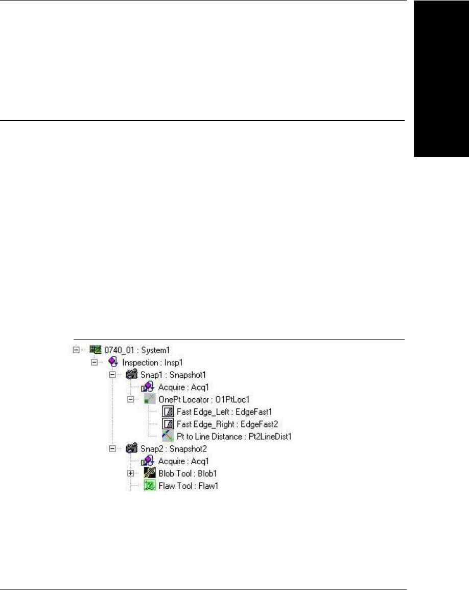
VsNameNode
Talking to Visionscape
Hardware:
3
Visionscape Programmer’s Kit (VSKit) Manual 3-23
would an actual loaded Job. Refer to the following section on the
VsNameNode object for more information.
VsNameNode
The VsNameNode object represents either a Step or Datum object. It’s
the object used to provide Namespace information for a Device, typically
a remote Device like a smart camera. When we say Namespace
information, we are primarily talking about the Job that is loaded on the
Device. You will access a Device’s Namespace via the VsDevice object’s
Namespace property, or the ListInspections and ListSnapshots functions
(refer to the previous section for more information). The following
example shows how you would access the Namespace of a given Device:
Dim nnNamespace As VsNameNode
m_Dev.QueryNamespace
Set nnNamespace = m_Dev.Namespace
VsDevice’s Namespace property returns a VsNameNode object that
represents the VisionSystem Step of the Job on the Device. Assume the
Namespace of a Device (the loaded Job) looks like this:
FIGURE 3–1. Namespace of the Device
Then, our sample code above would return a VsNameNode object that
represented the Step named “0740_01” (symbolic name = System1).
When we say it “represents” the Step, we mean it’s an object that
contains information that describes that Step, it’s not the actual Step.
Every VsNameNode object is also a collection. It holds a collection of all

Chapter 3Talking to Visionscape Hardware: VsCoordinator and VsDevice
3-24 Visionscape Programmer’s Kit (VSKit) Manual
of the child Steps AND Datums of the Step that it represents. This means
that you can walk through the elements of the VsNameNode object, just
as you can walk through the elements of a Job tree. The following is some
sample code that demonstrates how you might walk through every
element of the VsNameNode tree. We will accomplish this task using a
recursive function:
Private sub AnalyzeNamespace(dev as VsDevice)
dev.QueryNamespace
WalkNameNodes dev.Namespace
End Sub
Private Sub WalkNameNodes(parentNode As VsNameNode)
Dim node As VsNameNode
'loop through all the child nodes
For Each node In parentNode
'DUMP INFO ON THIS NODE
'is it a Step or a Datum?
If node.NameType = NAMETYPE_DATUM Then
Debug.Print "Datum Name = " & node.UserName
Debug.Print "Datum SymName = " &
node.SymbolicName
Debug.Print "Datum Type = " & node.ProgId
Select Case node.NameCat
Case VS_INPUT_DATUM
Debug.Print "Datum Category = INPUT"
Case VS_OUTPUT_DATUM
Debug.Print "Datum Category = OUTPUT"
Case VS_RESOURCE_DATUM
Debug.Print "Datum Category = RESOURCE"
End Select
ElseIf node.NameType = NAMETYPE_STEP Then
Debug.Print "Step Name = " & node.UserName
Debug.Print "Step SymName = " &
node.SymbolicName
Debug.Print "Step Type = " & node.ProgId
Select Case node.NameCat
Case VS_POSTPROC_STEP
Debug.Print "Step Category = PostProc"
Case VS_PREPROC_STEP
Debug.Print "Step Category = PreProc"
Case VS_PRIVATE_STEP
Debug.Print "Step Category = Private"

VsNameNode
Talking to Visionscape
Hardware:
3
Visionscape Programmer’s Kit (VSKit) Manual 3-25
Case VS_SETUP_STEP
Debug.Print "Step Category = Setup"
End Select
End If
'does this node have any children?
If node.Count > 0 Then
'yes, so walk them as well
WalkNameNodes node
End If
Next
End Sub
Using an approach like the example above, you can walk through an
entire Job and examine its contents. Now that you now how to access any
VsNameNode in the Namespace tree, your next question would be, what
information does VsNameNode provide me?
VsNameNode Properties
As we've already said, a VsNameNode represents either a Step or a
Datum. Therefore, the properties are intended to describe that Step or
Datum.
• Property NameType As tagNAMENODE_TYPE
This property returns a value that identifies the type of object
represented by the NameNode. Possible values are:
– NAMETYPE_DATUM — The NameNode represents a Datum
object.
– NAMETYPE_STEP — The NameNode represents a Step object.
– NAMETYPE_FIELD — The NameNode represents a field.
• Property NameCat As tagNAMENODE_CAT
Returns a value that indicates the category of the Step or Datum. This
is roughly equivalent to the Category property of Step and Datum.
Possible values for Datums:
– VS_INPUT_DATUM
– VS_OUTPUT_DATUM

Chapter 3Talking to Visionscape Hardware: VsCoordinator and VsDevice
3-26 Visionscape Programmer’s Kit (VSKit) Manual
– VS_RESOURCE_DATUM
Possible values for Steps:
– VS_POSTPROC_STEP
– VS_PREPROC_STEP
– VS_PRIVATE_STEP
– VS_SETUP_STEP
– VS_PART_STEP
• Property ProgID As String
Returns a string that is equivalent to the Step and Datum object’s
Type property. This is in the form “Step.type.1” or “Datum.type.1”
where “type” would represent the actual type of the Step or Datum.
• Function SymbolicName As String
The symbolic name of the Step or Datum. This is equivalent to the
NameSym property of Step and Datum. Return value is a string.
• Property TaggedForUpload As Long
Only applies to Datums. Returns 1 if this Datum has been selected for
upload, 0 if not. In other words, this Datum was added to the
Inspection Step’s “Select Results to Upload” list and will, therefore,
show up in the list of results in each inspection report.
• Property UserName As String
The user assigned name of the Step or Datum. This is equivalent to
the Name property of Step and Datum. Return value is a string.
• Property GUID As String
A string that represents the actual GUID of the object
• Property Handle As Long
This is functionally equivalent to the Handle property of the Step and
Datum objects.

VsNameNode
Talking to Visionscape
Hardware:
3
Visionscape Programmer’s Kit (VSKit) Manual 3-27
• Property Inspection As IVsNameNode
Returns a reference to a VsNameNode that represents the parent
Inspection Step.
• Property Parent As IVsNameNode
Returns a reference to the parent VsNameNode.
• Property Count as Long
Returns a count of how many child VsNameNodes are in your
collection.
• Property Device As IVsDevice
Returns a reference to the VsDevice object that produced this
VsNameNode.
VsNameNode Methods
• Property SearchForType (ByVal bstrType As String) As
IVsNameNodeCollection
Allows you to search for all of the child nodes that are of the type
specified by the bstrType parameter. A VsNameNodeCollection is
returned that contains all of the nodes found.
Dim nnAllFastEdge as VsNameNodeCollection
'Find all the child Fast Edge steps of this name node
Set nnAllFastEdge = ThisNameNode.SearchForType("Step.Edgefast.1")
'loop through them all
Dim nnFastEdge
For Each nnFastEdge in nnAllFastEdge
Debug.Print nnFastEdge.UserName
Next
• Property FindParentOfType (ByVal ProgID As String) As
IVsNameNode
Allows you to search for a parent Step or Datum that is of the type
specified by the ProgId parameter. A VsNameNode reference is
returned.

Chapter 3Talking to Visionscape Hardware: VsCoordinator and VsDevice
3-28 Visionscape Programmer’s Kit (VSKit) Manual
Dim nnParentSnap as VsNameNode
'Find the parent snapshot step of this name node
Set nnParentSnap = ThisNameNode.FindParentOfType("Step.Snapshot.1")
• Property MakePath ([ByVal StopAtType As
String"Step.Inspection.1"]) As String
Builds a path string from the current node up to the first parent node
that is of the type specified by the optional StopAtType parameter.
StopAtType defaults to the Inspection step.
• Property SearchForTagged ([ByVal bstrTypeIn As String]) As
IVsNameNodeCollection
Returns a collection of name nodes that are selected for upload. This
only applies to Datums, so only VsNameNodes that represent
Datums will be in the list. The optional bstrTypeIn parameter can be
used when you only want your list to include datums of a certain type.
'get a list of all Datums selected for upload
Set uploadList = nnNamespace.SearchForTagged
'get a list of just Point Lists that are
'selected for upload
Set uploadList = nnNamespace.SearchForTagged("Datum.PtList.1")
A Detailed Look at VsCoordinator
In general, you will use VsCoordinator to provide access to the list of
available Devices. VsCoordinator does have other advanced uses,
however. In this section, we will take a detailed look at all of
VsCoordinator’s capabilities.
Device Collection
All devices are accessible via the Devices collection property of
VsCoordinator. You can iterate over accessible devices using code such
as:
Dim coord as new VsCoordinator
Dim dev as VsDevice
For each dev in coord.Devices
' do something with device
Next dev

A Detailed Look at VsCoordinator
Talking to Visionscape
Hardware:
3
Visionscape Programmer’s Kit (VSKit) Manual 3-29
DeviceFocusSet
Most controls in VsKit get a reference to the VsDevice object they’ll be
connecting to by handling the OnDeviceFocus event from VsCoordinator.
There are two ways to manually set the device focus.
• If you already have the VsDevice object and want to send the
OnDeviceFocus event to all other controls, then you can use the
DeviceFocusSet method. For example:
' dev is a VsDevice object obtained somehow, we want all controls to "focus" on this
device
Coord.DeviceFocusSet dev
This will cause the OnDeviceFocus event to be sent to by all other
“instances” of VsCoordinator, and for some VsKit controls (if in
AutoConnect mode), this could create a connection to the device to
perhaps get results, charts, etc.
• There is also a OnDeviceFocusChanging event that is fired before
the actual OnDeviceFocusChanged event, which is useful if there is
some processing to do before any other control handles the
OnDeviceFocus event.
To clear the device focus, use the Nothing keyword to signify that no
device is selected:
Coord.DeviceFocusSet Nothing
You can retrieve the device with the focus at any time by calling the
DeviceFocusGet method. Be sure to always check if the device is valid,
by always writing code such as:
dev = Coord.DeviceFocusGet
If (not dev is Nothing) then
' do something
End if
Grouping Controls Using GroupID
We recommend you use DeviceFocusSet, since there is a second default
parameter to this method, which is called GroupID. For applications
where only one device is used at a time, leave GroupID at its default
value of -1. However, this is a way to have more than one device selected
at a time; simply assign each DeviceFocusSet a different GroupID. The

Chapter 3Talking to Visionscape Hardware: VsCoordinator and VsDevice
3-30 Visionscape Programmer’s Kit (VSKit) Manual
OnDeviceFocus event will indicate which group the device belongs to.
This same optional GroupID parameter appears in many of the methods
of VsCoordinator, and GroupID is a property of many of the VsKit
controls.
Device Focus Property
It’s also possible to use a shorthand method to set and get the device
focus in situations where a GroupID is not necessary. You can simply use
the DeviceFocus property of VsCoordinator:
Set dev = coord.DeviceFocus
or
Set coord.DeviceFocus = dev
DeviceFocusSetOnDiscovery
There is another way of manually setting the device focus when you don’t
have the device object, but know the name of the device you are
interested in. In this event, you would use the
DeviceFocusSetOnDiscovery method. For example, to set the device
focus to “MyCamera”:
Coord.DeviceFocusSetOnDiscovery "MyCamera"
This will cause the OnDeviceFocus event to be sent when MyCamera is
discovered (either immediately or after a five second delay if no UDP
packets have yet been received).
Finding a Device by Name or IP
You can also look up a device in the coord.Devices list quickly by using
the FindDeviceByName method. For example:
Set dev = coord.FindDeviceByName ("MyCamera")
If (Not dev is nothing) then
' do something
End If
If you do not know the name of the device, but know the IP Address, use
the FindDeviceByIP method. For example:

A Detailed Look at VsCoordinator
Talking to Visionscape
Hardware:
3
Visionscape Programmer’s Kit (VSKit) Manual 3-31
Set dev = coord.FindDeviceByIP ("10.2.1.198")
If (Not dev is nothing) then
' do something
End If
You can also get the name of the device with a given IP address by using
the LookupIPAddress function.
Dim devname as String
devname = coord.LookupIPAddress ("10.2.1.198")
OnDeviceDiscovered Event
The OnDeviceDiscovered event is fired whenever a new device has been
found, and sometimes this is useful but, for the most part, the approaches
described above are preferred to connect to a new device.
Using Message Broadcasting to Simplify Application
Design
There are some functions of VsCoordinator that help with organizing a
project in which information needs to be shared between different
components. The most useful of these is the Broadcast mechanism. By
using the methods BroadcastMessage or BroadcastObj, you can cause
the OnBroadcastMessage or OnBroadcastObj events to be raised for all
other VsCoordinators. For example, let’s say you have a button on a form,
and when you press it you want all other forms to receive an event. You
can do this as follows:
Private Sub Command1_Click()
Coord.BroadcastMessage Me.Name, "MyPrivateMessage", "param"
End Sub
•The first parameter is a name that identifies the originator of the
message. In this example, we are using the form name that is
accessed using Me.Name. If this code was in a user control, you
would use UserControl.Name instead. You will see why the name is
important in a moment.
•The second parameter is a string that represents the actual message
to be broadcast.
•The third parameter is optional; you can use it to add additional
parameters to the message.

Chapter 3Talking to Visionscape Hardware: VsCoordinator and VsDevice
3-32 Visionscape Programmer’s Kit (VSKit) Manual
The BroadcastMessage function will cause the OnBroadcastMessage
event to fire for every VsCoordinator in the application. For example, if
another form was interested in this message, you would implement the
OnBroadcastMessage event as follows:
Dim WithEvents coord As VsCoordinator
Set coord = new VsCoordinator
Private Sub coord_OnBroadcastMessage(ByVal bstrSender As String, _
ByVal bstrMsg As String, ByVal bstrParam As String)
If (bstrSender = Me.Name) Then Exit Sub
Select Case bstrMsg
Case "MyPrivateMessage"
' do something
End Select
End Sub
Notice the first statement that exits if the bstrSender parameter is the
same as the name of the form. This is simply a way of checking if the
broadcast came from this form or from somewhere else. Is may not be
necessary depending on what you are doing, but it’s often the case that
the originator of a message does not want to handle the message
themselves.
Then, the Select Case statement can key on the text of the sent message
to suit your particular purpose.
A variation of the broadcast message allows you to send an object as the
parameter. For example:
Dim MyObj as new SomeObject
Private Sub Command1_Click()
Coord.BroadcastMessage Me.Name, "MyPrivateMessage", MyObj
End Sub
And the event handler:
Private Sub coord_OnBroadcastObj(ByVal bstrSender As String,
ByVal bstrMsg As String, ByVal obj As Object)
If (bstrSender = Me.Name) Then Exit Sub
Select Case bstrMsg
Case "MyPrivateMessage"
Dim MyObj as SomeObject
Set MyObj = obj
If (Not MyObj is Nothing) then
' Do Something

A Detailed Look at VsCoordinator
Talking to Visionscape
Hardware:
3
Visionscape Programmer’s Kit (VSKit) Manual 3-33
End If
End Select
End Sub
Global Strings
Another useful way of sharing information between components is to use
the SetGlobalString and LookupGlobalString functions. For example, let’s
say you want every component to have access to the current file name.
You can accomplish this as follows:
Dim Filename as String
Filename = "foo.bar"
Coord.SetGlobalString "MyFileName", Filename
The first parameter is a key that you can use later to retrieve the string.
Now, any other component can use VsCoordinator to obtain the file name
by using the “MyFileName” key:
Dim Filename as String
Filename = Coord.LookupGlobalString("MyFileName")
UpdateUI Method
Calling the UpdateUI of VsCoordinator causes the OnUpdateUI event to
be raised for every VsCoordinator reference. You can use this method as
a way to inform every form or control that something has changed that
requires a display update. For more complex projects, the
BroadcastMessage approach is preferred because you can define your
own messages.
LogMessage and the Debug Window
As an aid to debugging, you can use the Visionscape debug window
(which is accessed via the AvpSvr taskbar application) to log messages, if
desired, by using the LogMesssage method:
Coord.LogMessage "Something important happened!", False
The second parameter should be set to True if you are reporting an error
condition (and will appear red in the display), and False if the message is
for information purposes only.

Chapter 3Talking to Visionscape Hardware: VsCoordinator and VsDevice
3-34 Visionscape Programmer’s Kit (VSKit) Manual
You can show or hide the debug window using the function
ShowLogWindow:
Coord.ShowLogWindow True ' to show the display
Coord.ShowLogWindow False ' to hide the display
Using VsFunctions to Synchronize UI Elements
A common user interface design issue is maintaining the enabled vs.
disabled or selected vs. unselected state of various UI elements. For
example, you might want to have a Download button, but it must be
disabled whenever a download is not permitted, and there may be many
conditions to check. The VsCoordinator provides a mechanism called
VsFunctions to simplify the synchronization of these UI components,
even across forms or controls. A VsFunction associates a symbolic name
for a particular function and an object to handle the function when it’s
evoked. The VsFunction object maintains information about enabled or
selected status, and can also optionally contain a value and a list of
strings representing an enumerated type. Creating a VsFunction requires
that you first create an object that implements the IVsFunctionHandler
interface. For example, let’s create a function called “DoMyThing” that
can be invoked from anywhere, including other forms or controls. Any
button that might invoke this function also needs to be enabled or
disabled from anywhere.
First, the VsFunction needs to have a handler defined; this is
accomplished by implementing the IVsFunctionHandler interface in a
control or form. The following is the relevant code to create a new
VsFunction:
Implements IVsFunctionHandler
Private fnDoMyThing as VsFunction
' in the initialization code
Set fnDoMyThing = coord.AddFunction("DoMyThing", Me)
' in the termination code
fnDoMyThing.Remove
Set fnDoMyThing = Nothing
' implementation of IVsFunctionHandler
Private Sub IVsFunctionHandler_DoFunction(ByVal objFn As VSOBJLib.IVsFunction,
ByVal bstrParam As String)

A Detailed Look at VsCoordinator
Talking to Visionscape
Hardware:
3
Visionscape Programmer’s Kit (VSKit) Manual 3-35
Select Case objFn.Name
Case "DoMyThing"
' do your thing
End Select
End Sub
You can invoke the DoMyThing function from anywhere else within the
same process:
Dim fn as VsFunction
Set fn = coord.GetFunction("DoMyThing")
If (Not fn is Nothing) then
fn.Invoke "optional string parameter"
End If
It’s also possible to store a value in the VsFunction, or to change highlight
or selected status:
fn.Value = 3
fn.Enabled = True
fn.Highlight = True
You can assign text names to go with the values using a semicolon
delimited string starting with the first item representing the text for value 0:
fn.Enum = "Item 0;Item 1;Item 2;Item 3"
Any time one of the fields of a VsFunction changes, the VsCoordinator
object will raise the OnFunctionEvent event:
Private Sub coord_OnFunctionEvent(ByVal ev As VSOBJLib.tagFNEVENTS, ByVal
objFn As VSOBJLib.IVsFunction)
' can handle a particular event for a function here
End Sub
The first parameter describes what has changed about the function;
possible values are:
• FN_ADD — The function has just been added.
• FN_CHANGED — The function has been changed.
• FN_ENUM_LIST_CHANGED — The list of enumerated strings has
changed.
• FN_PRE_INVOKE — The function is about to be invoked.

Chapter 3Talking to Visionscape Hardware: VsCoordinator and VsDevice
3-36 Visionscape Programmer’s Kit (VSKit) Manual
• FN_POST_INVOKE — The function was invoked.
• FN_REMOVE — The function is about to be removed.
• FN_VALUE_CHANGED — The function value field has changed.
• FN_VALUE_REFRESH — The function Refresh function has been
called.
If you have a DoMyThing button that you want to reflect the state of the
function, you need to handle OnFunctionEvent as follows:
Private Sub coord_OnFunctionEvent(ByVal ev As VSOBJLib.tagFNEVENTS, ByVal
objFn As VSOBJLib.IVsFunction)
If (objFn.Name = "DoMyThing") then
btnDoMyThing.Enabled = objFn.Enabled
End If
End Sub
You would do something similar using the Highlight property to show a
depressed button or checkbox.
Getting Information About Local Network Interface
Controllers
You can retrieve the state of any local Network Interface Controller
devices using the NetworkAdapters property of VsCoordinator. You can
use a VsNetworkAdapter to traverse this collection:
Dim nic As VsNetworkAdapter
For Each nic In coord.NetworkAdapters
Debug.Print "Description = " & nic.Caption
Debug.Print "Gateway = " & nic.DefaultIPGateway
Debug.Print "DHCP = " & nic.DHCPEnabled
Debug.Print "DHCP Server = " & nic.DHCPServer
Debug.Print "IP Address = " & nic.IPAddress
Debug.Print "Subnet Mask = " & nic.IPSubnet
Debug.Print "MAC Address = " & nic.MACAddress
Next nic
You can check for changes to the network adapters by calling the
RefreshNetworkAdapters method. If the list of network adapters has
changed since your application started, or since the last time you called
RefreshNetworkAdapters, then the OnNICChange event will be raised.

VsCoordinator Reference
Talking to Visionscape
Hardware:
3
Visionscape Programmer’s Kit (VSKit) Manual 3-37
For example, if a wireless connection has been made or dropped, or a
change has been made to the network configuration via the control panel.
VsCoordinator Reference
Device Enumeration and Device Focus
• Property Get Devices() As IVsDeviceCollection
This property is a collection of all vision devices that can be
connected to.
• Function FindDeviceByName(ByVal strName As String) As
IVsDevice
This function looks up a device by specifying its name. This function
returns a VsDevice object if found, and returns Nothing if not found.
• Property Get DeviceFocus() As IVsDevice
This property returns the device that currently has the focus (set with
DeviceFocusSet). The assumption is that GroupID has not been
used. If GroupID has been used, then use DeviceFocusGet instead.
• Property Let DeviceFocus(dev As IVsDevice)
This property sets the focus device by specifying a VsDevice object.
• Function LookupIPAddress(ByVal Name As String) As String
Use this function to look up a device by specifying its name. It returns
the device's IP address if found, and an empty string if not found.
• Sub DeviceFocusSet(ByVal pDevice As IVsDevice, ByVal nGroupID
As Long)
This method sets the focus device by specifying a VsDevice object.
Use the optional GroupID parameter in situations where multiple
focus devices are required.
• Function DeviceFocusGet(ByVal nGroupID As Long) As IVsDevice

Chapter 3Talking to Visionscape Hardware: VsCoordinator and VsDevice
3-38 Visionscape Programmer’s Kit (VSKit) Manual
This function returns the current focus device. Use the optional
GroupID parameter if multiple focus devices have been specified.
• Function FindDeviceByIP(ByVal strIP As String) As IVsDevice
This function searches the Device collection by the supplied IP
Address string. It returns a VsDevice if found, and Nothing if not
found.
• Sub DeviceFocusSetOnDiscovery(ByVal bstrName As String, ByVal
GroupID As Long)
This method sends a OnDeviceFocus event when the specified
device name is available for use. For network devices (i.e., smart
cameras) this is the preferred method for connecting.

VsCoordinator Reference
Talking to Visionscape
Hardware:
3
Visionscape Programmer’s Kit (VSKit) Manual 3-39
• Public Event OnDeviceDiscovered(ByVal newDevice As IVsDevice)
This event occurs when a new network device (i.e., smart camera) is
discovered.
• Public Event OnDeviceFocus(ByVal objDevice As IVsDevice)
This event occurs when a focus device is selected via the
DeviceFocusSet method.
• Public Event OnDeviceLost(ByVal dev As IVsDevice)
This event occurs when a device can no longer be communicated
with; for example, if it has been physically disconnected.
• Public Event OnDeviceFocusChanging(ByVal objDevice As
IVsDevice, ByVal nGroupID As Long)
method OnDeviceFocusChanging.
• Public Event OnDeviceFocusEx(ByVal objDevice As IVsDevice,
ByVal nGroupID As Long)
This event is similar to the OnDeviceFocus event, except it provides
the GroupID. This is primarily useful if there are multiple focus
devices.
UI Coordination
• Sub UpdateUI
This method sends the OnUpdateUI event from all VsCoordinators.
Use this to force various controls to refresh.
• Sub BroadcastMessage(ByVal bstrSender As String, ByVal bstrMsg
As String, ByVal bstrParam As String)
This method sends the OnBroadcastMessage from all
VsCoordinators. Use this to send coordinating messages between
controls. The bstrMsg parameter is a user defined string that
identifies the action to be taken. Use the bstrParam to supply
additional information.

Chapter 3Talking to Visionscape Hardware: VsCoordinator and VsDevice
3-40 Visionscape Programmer’s Kit (VSKit) Manual
• Sub BroadcastObj(ByVal bstrSender As String, ByVal bstrMsg As
String, ByVal obj As Object)
This method sends the OnBroadcastMessage from all
VsCoordinators. Similar in function to the BroadcastMessage
function, except that an object can be passed as a parameter.
• Sub SetGlobalString(ByVal bstrKey As String, ByVal bstrString As
String)
This method associates a string with a symbolic name so that it can
be retrieved later, even from a different form or module.
• Function LookupGlobalString(ByVal bstrKey As String) As String
This function retrieves a Global String that was set via the
SetGlobalString function.
• Property Get Functions() As IVsFunctionCollection
This property returns the collection of VsFunctions that have been
defined. Please refer to the documentation for more information on
VsFunctions. For more information, see “Using VsFunctions to
Synchronize UI Elements” on page 3-34.
• Function GetFunction(ByVal Name As String) As IVsFunction
This function retrieves a VsFunction by name. Please refer to the
documentation for more information on VsFunctions. For more
information, see “Using VsFunctions to Synchronize UI Elements” on
page 3-34.
• Function AddFunction(ByVal Name As String, ByVal objHandler As
IVsFunctionHandler) As IVsFunction
This function adds a new VsFunction. Please refer to the
documentation for more information on VsFunctions. For more
information, see “Using VsFunctions to Synchronize UI Elements” on
page 3-34.
• Sub RemoveFunction(ByVal Name As String)
This method removes an existing VsFunction by name. Alternatively,
you can call the Remove method of the VsFunction object. Please
refer to the documentation for more information on VsFunctions. For

VsCoordinator Reference
Talking to Visionscape
Hardware:
3
Visionscape Programmer’s Kit (VSKit) Manual 3-41
more information, see “Using VsFunctions to Synchronize UI
Elements” on page 3-34.
• Sub InvokeFunction(ByVal bstrName As String, ByVal bstrParam As
String)
This method invokes a previously defined VsFunction by name and
passes an optional string parameter. Please refer to the
documentation for more information on VsFunctions. For more
information, see “Using VsFunctions to Synchronize UI Elements” on
page 3-34.
• Public Event OnFunctionEvent(ByVal ev As tagFNEVENTS, ByVal
objFn As IVsFunction)
This event occurs when a VsFunction value has changed.
• Public Event OnUpdateUI
This event occurs as a result of calling the UpdateUI method.
• Public Event OnBroadcastMessage(ByVal bstrSender As String,
ByVal bstrMsg As String, ByVal bstrParam As String)
This event occurs as a result of calling the BroadcastMessage
method.
• Public Event OnBroadcastObj(ByVal bstrSender As String, ByVal
bstrMsg As String, ByVal obj As Object)
This event occurs as a result of calling the BroadcastObj method.
• Public Event OnNICChange
This event occurs if a change has been made to any Network
Interface Controller settings (for example, the host PC's IP address or
Net Mask).
Miscellaneous
• Sub ShowLogWindow(ByVal bShow As Boolean)
This method shows or hides the Visionscape debugging window.
• Sub LogMessage(ByVal strMsg As String, ByVal bError As Boolean)

Chapter 3Talking to Visionscape Hardware: VsCoordinator and VsDevice
3-42 Visionscape Programmer’s Kit (VSKit) Manual
This method displays a message to the Visionscape debugging
window. If bError is True, then the message is displayed in red.
• Property Get Job() As Unknown
This property returns the currently loaded Job. Please refer to the
detailed documentation for further information about the Job property.
For more information, see “Connecting Jobs to Visionscape Devices”
on page 3-6.
• Property Let Job(jobin As Unknown)
This property sets the current Job. Please refer to the detailed
documentation for further information about the Job property. For
more information, see “Connecting Jobs to Visionscape Devices” on
page 3-6.
• Property Get NetworkAdapters() As IVsNetworkAdapterCollection
This property returns a collection of VsNetworkAdapter objects,
containing information about the Network Interface Controllers on the
PC.
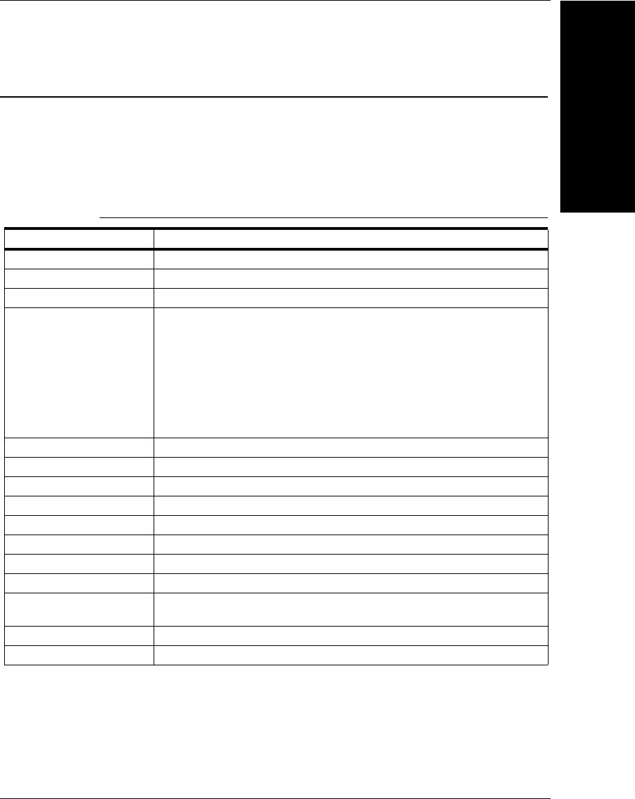
VsDevice Reference
Talking to Visionscape
Hardware:
3
Visionscape Programmer’s Kit (VSKit) Manual 3-43
VsDevice Reference
Identification and Information
Table 3–2 summarizes the identification and informational properties of
VsDevice.
TABLE 3–2. Identification Properties of VsDevice
Property Name Description
Name The name of the Device. For smart cameras, this name is user assigned.
Key A unique key string identifying the device.
DirectoryID An ID that identifies the device in the VsDirectory structure.
DeviceClass The class of device. The value can be one of the following:
DEVCLASS_UNKNOWN=0
DEVCLASS_SOFTWARE_EMULATED=1
DEVCLASS_HOST_BOARD=2
DEVCLASS_PROCESSOR_BOARD=3
DEVCLASS_SMART_CAMERA=4
DEVCLASS_SMART_CAMERA_OLDER=5
DEVCLASS_SMART_CAMERA_UNREACHABLE=6
DEVCLASS_CAMERA=7
DeviceModel The device model number
DigitizerModel The digitizer model number
IsHostBased True if the host PC's CPU is used to run the inspections.
SoftwareVersion A string representing the software revision loaded on the device
IPAddress The IP address of the device.
MACAddress The MAC address of the device
NetMask The Network Mask of the device
NetworkConnectable True if the device is on the same subnet as the host PC
TimeSinceLastRefresh The time in milliseconds since the last UDP info message has been received
from the device.
NameOfController The name or IP address of the PC that has control of the device
IsInTryout True if the device is in Tryout mode

Chapter 3Talking to Visionscape Hardware: VsCoordinator and VsDevice
3-44 Visionscape Programmer’s Kit (VSKit) Manual
Download / Upload Job
• Function Download(ByVal objVS As IVisionSystemStep, ByVal
bAsync As Long) As Long
This function downloads a Job to the device by specifying a
VisionsSystemStep. Set the bAsync parameter to True to avoid
hanging the user interface for the duration of the download.
• Function DownloadAVP(ByVal filename As String, ByVal bAsync As
Long) As Long
This function downloads a Job to the device by specifying an AVP file
name path. Set the bAsync parameter to True to avoid hanging the
user interface for the duration of the download.
• Function Upload(ByVal pJob As IJobStep, ByVal objVS As
IVisionSystemStep, ByVal bAsync As Long) As Long
This function uploads a Job from a device. Refer to the detailed
documentation for further information on uploading. For more
information, see “Uploading a Job” on page 3-15.
IsInLive True if the device is in acquire live mode
IsInAcquire True if the device is acquiring an image for setup
HaveControl True if the current process has taken control of the device by using the
TakeControl method
DeviceState The current state of the device. Can be one of the following values:
DEVSTATE_UNKNOWN=0
DEVSTATE_RUNNING=1
DEVSTATE_STOPPED=2
DEVSTATE_NOJOB=3
DEVSTATE_NOCOMM=4
DEVSTATE_ERROR=100
DEVSTATE_FILE_XFER=101
DEVSTATE_TRYOUT=102
DEVSTATE_EDIT=103
DEVSTATE_LIVE=104
DEVSTATE_FUNCTION=105
DEVSTATE_ACQUIRE=106
TABLE 3–2. Identification Properties of VsDevice (continued)
Property Name Description

VsDevice Reference
Talking to Visionscape
Hardware:
3
Visionscape Programmer’s Kit (VSKit) Manual 3-45
• Function CheckXferStatus(ByVal sleep_ms As Long) As
tagXFERSTATUS
After initiating an upload or download in asynchronous mode, call the
CheckXferStatus function in a loop until the transfer is complete. The
sleep_ms parameter specifies the number of milliseconds to sleep if
the transfer is not complete. It’s recommended that the loop contain a
DoEvents call so that the user interface remains responsive.
Control
• Function TakeControl(ByVal bstrUID As String, ByVal bstrPWD As
String) As Boolean
This function allows you to TakeControl of the smart camera by
logging in with a User ID and Password.
• Property Get HaveControl() As Boolean
This property returns True if you currently have control.
• Sub ReleaseControl
This method releases control of a smart camera.
• Sub StartInspection(ByVal nInsp As Long, ByVal nCycles As Long)
This method starts an inspection on the device. It will fail if you do not
have control. If no parameters are specified, then all inspections are
started. You can use the nInsp parameter to identify an inspection
index. You can use the nCycles parameter to specify the number of
cycles to run.
dev.StartInspection ' start all inspections
dev.StartInspection N ' start inspection N
dev.StartInspection N, 2 ' start inspection N and run for 2 cycles
• Sub StopInspection(ByVal nInsp As Long)
This method stops an inspection on the device. It will fail if you do not
have control. By default, all inspections are stopped. You can use the
nInsp parameter to identify an inspection index.
dev.StopInspection ' stop all inspections
dev.StopInspection N ' stop inspection N

Chapter 3Talking to Visionscape Hardware: VsCoordinator and VsDevice
3-46 Visionscape Programmer’s Kit (VSKit) Manual
• Function IsInspectionRunning(ByVal nInsp As Long) As Boolean
This function returns True if the specified inspection is running on the
device.
• Property Get IsAnyInspectionRunning() As Boolean
This property returns True if any inspection is running on the device.
• Property Get NumInspections() As Long
This property returns the number of inspections on the device.
• Property Get NumSnapshots(ByVal nInsp As Long) As Long
This property returns the number of Snapshot Steps contained in the
specified inspection.
• Sub ResetCounters(ByVal nInsp As Long)
This method resets the inspection counters for the specified
inspection.
• Function ResetDevice(ByVal bstrUser As String, ByVal bstrPassword
As String) As Long
This function resets the Network Device. It requires that you specify a
username and password. The device will reboot.
Advanced
• Function QueryIOCaps() As IVsIOCaps
This function queries the device for a structure that describes the I/O
capabilities, such as the number of each type of I/O supported.
• Property Get UDPInfo() As IVsUDPInfo
This property returns a structure with all the information contained in
the UDP info packet sent by smart camera network devices.

VsDevice Reference
Talking to Visionscape
Hardware:
3
Visionscape Programmer’s Kit (VSKit) Manual 3-47
• Property Get ProgramController() As Unknown
If a Job is loaded into host memory, each VisionSystemStep can be
accessed via its “Program Controller” interface. This property
provides the means to access that interface.
• Sub GetDeviceBufferDm(ByVal bstrPath As String, ByVal objBufDm
As IBufferDm)
Use this method to directly read a buffer out of a device and copy the
data into the supplied BufferDm. The bstrPath parameter should be
the symbolic name path of the Buffer desired.

Chapter 3Talking to Visionscape Hardware: VsCoordinator and VsDevice
3-48 Visionscape Programmer’s Kit (VSKit) Manual

Visionscape Programmer’s Kit (VSKit) Manual 4-1
4
Viewing Images and
Results w/VSRunView
4
CHAPTER 4 Viewing Images and
Results wLWKVSRunView
Control
Visionscape Runtime Toolkit
The Visionscape Runtime Toolkit (VsRunKit) provides one very powerful
control called VsRunView. This control provides a very easy way to watch
images and results from any number of inspections and snapshots
running on a given Visionscape Device. To add this component to your
Visual Basic 6 Project, go to the Project menu, select “Components”, and
in the Components dialog, select the following library:
+Visionscape Controls: VsRunKit
The VsRunView Control
VsRunView is a very powerful and easy to use control. It makes it very
easy to view all the images from every snapshot on a given device, and
also to view all of the runtime statistics and uploaded results from every
inspection running on that Device. Consider the Job shown in Figure 4–1:
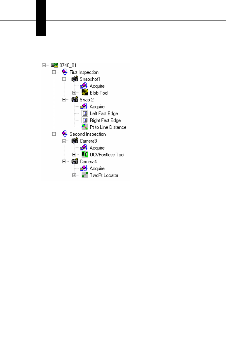
Chapter 4Viewing Images and Results w/VSRunView Control
4-2 Visionscape Programmer’s Kit (VSKit) Manual
FIGURE 4–1. Job to Consider
As you can see, this Job contains two inspections named “First
Inspection” and “Second Inspection”. Each of these Inspection Steps
contains two Snapshots, for a total of 4 Snapshots in the Job. In your UI,
you would want the user to be able to view the images of all 4 snapshots,
and you may also want them to be able to view the uploaded results from
the 2 inspections. If you’ve already added the code we demonstrated in
previous chapters to load this AVP and download it to your Device, then
the only remaining step is to drag a VsRunView control onto your
application’s main form, and then call its AttachDevice method.
• Sub AttachDevice(dev As VsDevice)
The dev parameter is a reference to the VsDevice whose images and
results you want to view. The VsRunView control will figure out how
many snapshots are present in the Job that is currently loaded on the
Device, it will then automatically generate an image view for each,
and it will put a button on a toolbar for each. These are called the
Snapshot buttons. The Snapshot buttons allow the user to select the
images they want to view. VsRunView will also figure out how many
Inspections are in the loaded Job, and an Inspection bar will be
added for each one at the bottom of the control. This bar shows the
inspection counts (inspected, passed, rejected); it can be expanded
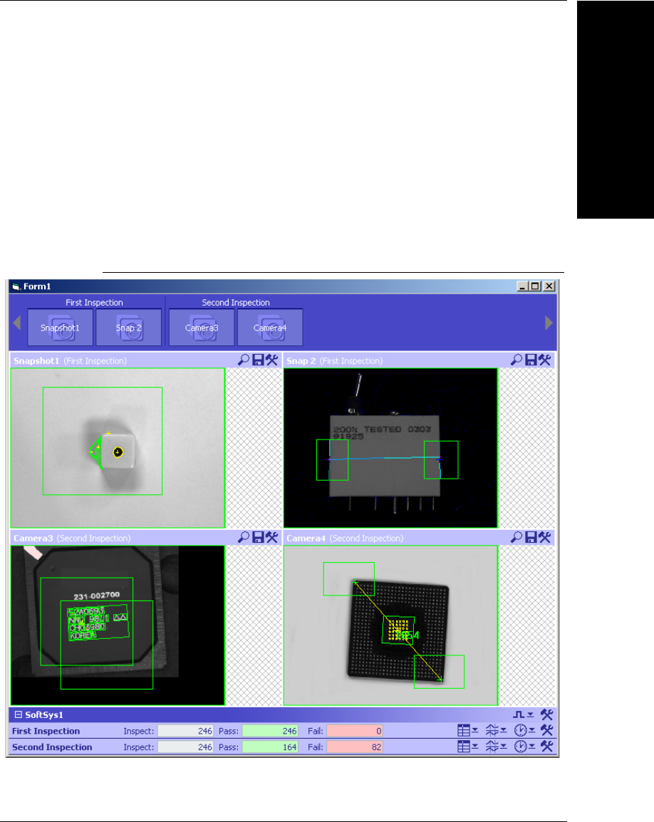
Visionscape Runtime Toolkit
Viewing Images and
Results w/VSRunView
4
Visionscape Programmer’s Kit (VSKit) Manual 4-3
to show all the uploaded results, timing stats, and timing graphs. If we
added the following two lines of code to our sample code from the
previous chapter, (right before calling StartInspection), and we were
running the above job, then we would produce a user interface that
looks something like Figure 4–2:
'assume our VsRunView control is named ctlRunView
ctlRunView.AttachDevice(m_dev) 'm_dev is our VsDevice
'tell VsRunview to display all snapshots
ctlRunView.OpenAllSnaps
FIGURE 4–2. VsRunView Displaying Our 2 Inspection 4 Snapshot Job
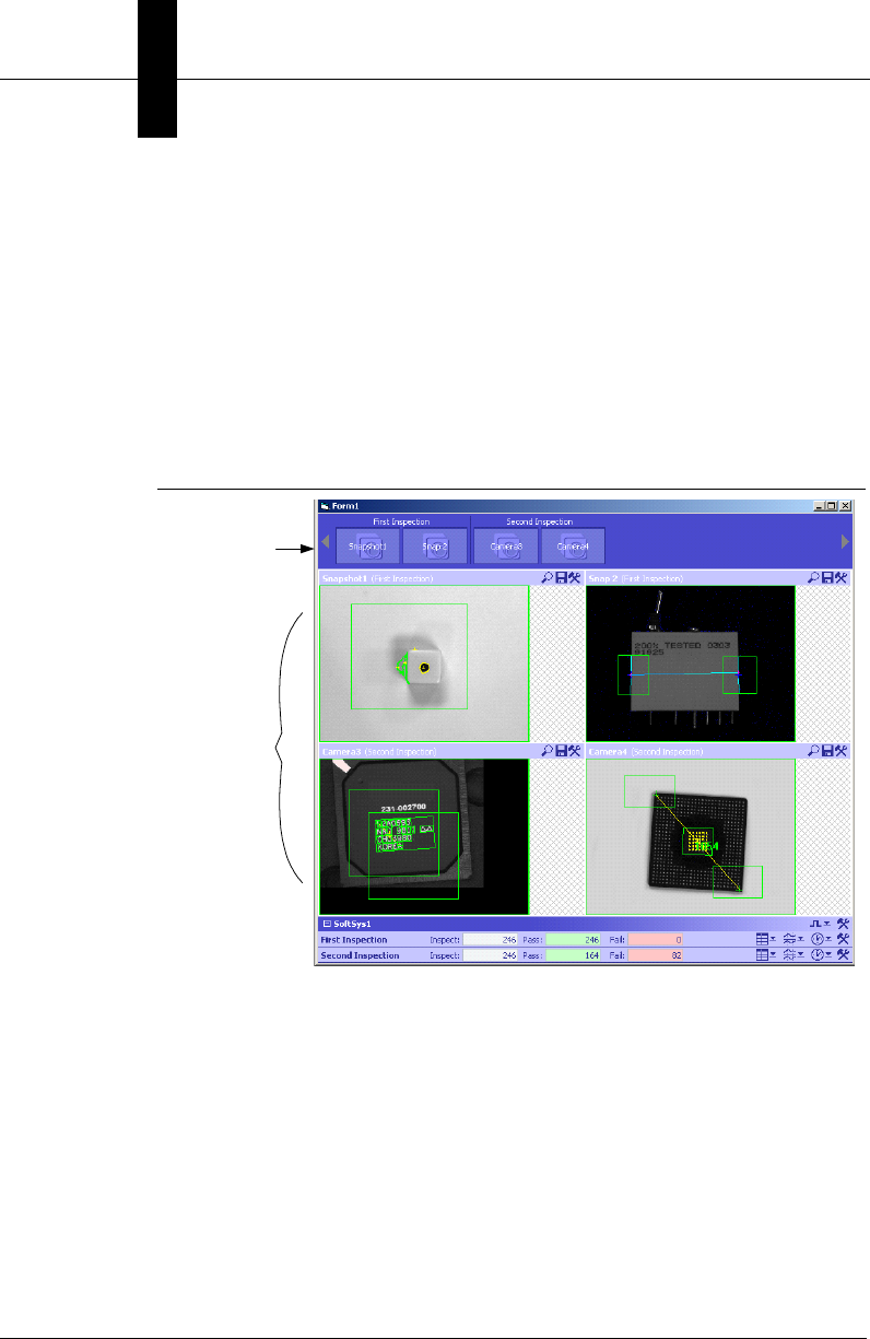
Chapter 4Viewing Images and Results w/VSRunView Control
4-4 Visionscape Programmer’s Kit (VSKit) Manual
You may notice that this screen looks very similar to FrontRunner's
runtime screen and AppRunner's main screen. That is because both
FrontRunner and AppRunner use the VsRunView control. Let’s discuss
the various areas of the control.
Snap Buttons and Snap Views
One Snap Button and One Snap View will be added to the VsRunView
control for every Snapshot found on the Device you attach to.
FIGURE 4–3. Snap Buttons and Snap Views
Snap Buttons
As Figure 4–3 shows, VsRunView added one Snap Button to the Snap
Buttons toolbar for all four of the Snapshots in our Job. The buttons are
grouped by their parent Inspection, and the name of the Inspection is
printed above. The name that you assign to each Snapshot Step is also
used as the text for each button. Clicking on one of the snap buttons will
cause VsRunView to display just that snapshot. If you hold down the Ctrl
key and click the snap buttons, you can view multiple snapshots at the
same time. Once a Snap Button has been pressed, clicking it again will
deselect it, and that Snapshot View will be removed.
Snap Buttons
Snap Views
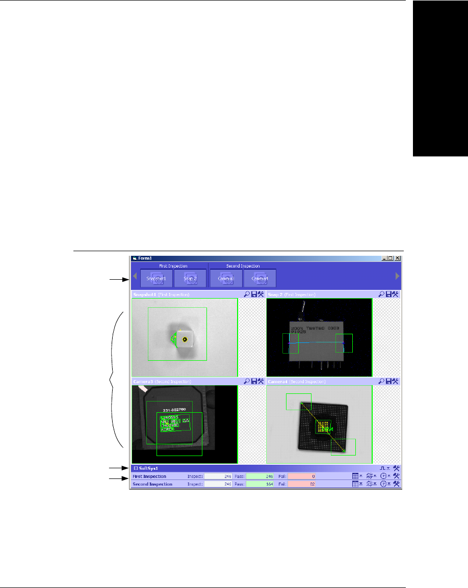
Visionscape Runtime Toolkit
Viewing Images and
Results w/VSRunView
4
Visionscape Programmer’s Kit (VSKit) Manual 4-5
Snap Views
The Snap View area is where your Snapshots are displayed. The title bar
of each view lists the name you assigned to the Snapshot Step and the
name of its parent Inspection step in parentheses. At the far right edge of
the title bar is a small toolbar that provides you with zooming options,
image saving options, and image display options (show all, show only
failures, etc.). Refer to the Visionscape FrontRunner User’s Manual for a
complete description of all options.
Device Views and Report Views
The Device View is a bar at the bottom of the VsRunView control that
groups together all of the Report Views for that Device. You will get one
Report View for each Inspection running on the device.
FIGURE 4–4. Device Views and Report Views
It’s possible to call VsRunView’s AttachDevice method for multiple
Devices and, in that case, you would have multiple Device Views at the
bottom of the control.
Snap Buttons
Snap Views
Device View
Report Views
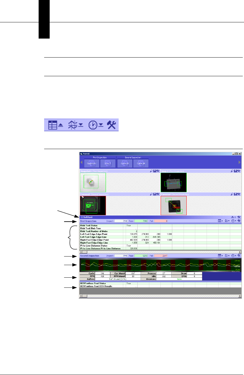
Chapter 4Viewing Images and Results w/VSRunView Control
4-6 Visionscape Programmer’s Kit (VSKit) Manual
Note: The support for multiple Devices has not been fully tested. Use this
feature at your own risk.
By default, each Result View will be collapsed and only show you the
inspection counts. By using the toolbar at the right end of the bar your
user can choose to display the uploaded results, a graph of your
inspections timing, and the inspections timing statistics.
FIGURE 4–5. Graph, Time, and Timing Statistics
So, as you can see, VsRunView provides a lot of capability while not
requiring you to write a large amount of code.
First Inspection’s Counts
First Inspection’s
Uploaded Results
Second Inspection’s Counts
Second Inspection’s Timing
Graph
Second Inspection’s
Uploaded Results
Second Inspection’s Stats
Device Bar

A Simple Application
Viewing Images and
Results w/VSRunView
4
Visionscape Programmer’s Kit (VSKit) Manual 4-7
A Simple Application
In the previous two chapters, we demonstrated how to load AVP files from
disk, and then how to discover and select your Visionscape Device for the
Job to run on. Now we’ll add a VsRunView control. Let's build upon the
sample code we demonstrated in the previous chapter, and make a
complete application that loads the sample job
“ProgSample_MultiCam.avp” included with the Development installation
of Visionscape. This AVP should be located in your \Vscape\Tutorials &
Samples\Sample Jobs folder.
1. In Visual Basic 6, create a new project, and select “Standard EXE” as
the type.
2. Go to the Project menu, select “References…”, and add the following
reference to your project:
+Visionscape Library: Device Objects
3. Go back to the Project menu, but this time select “Components…”,
and add the VsRunkit component to your project:
+Visionscape Controls: VsRunKit
4. VsRunkit should now show up in the Visual Basic 6 toolbox. The Icon
should look like this:
Open your project’s Form, select VsRunkit in the toolbox, and then
click on the form and drag in order to add the VsRunkit control. It
should look something like this:
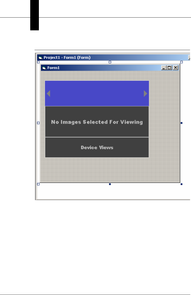
Chapter 4Viewing Images and Results w/VSRunView Control
4-8 Visionscape Programmer’s Kit (VSKit) Manual
FIGURE 4–6. Your Form Should Look Like This
5. In the Properties view, change the name of the control to ctlRunView.
6. Now, add the following code to Form1’s code window:
Private m_coord As VsCoordinator
Private m_dev As VsDevice
Private Sub Form_Load()
'instantiate our VsCoordinator
Set m_coord = New VsCoordinator
'now select the first available device
Set m_dev = m_coord.Devices(1)
'open and download our example AVP
m_dev.DownloadAVP "C:\vscape\Tutorials &

A Simple Application
Viewing Images and
Results w/VSRunView
4
Visionscape Programmer’s Kit (VSKit) Manual 4-9
Samples\Sample Jobs\ProgSample_MultiCam.avp"
While m_dev.CheckXferStatus(100) = XFER_IN_PROGRESS
DoEvents 'so VB does not appear to hang
Wend
'connect VsRunkit to the device
ctlRunView.AttachDevice m_dev
'tell VsRunView to display all snapshot views
ctlRunView.OpenAllSnaps
'Start all inspections
m_dev.StartInspection
End Sub
Private Sub Form_Resize()
'size our control to fill the form
ctlRunView.Move 0, 0, Me.ScaleWidth, Me.ScaleHeight
End Sub
Private Sub Form_Unload(Cancel As Integer)
'if running on a host board or software system,
' be sure to stop inspections before exiting
'if a Smart Camera, you can leave this line out
m_dev.StopInspection
'disconnect our control
ctlRunView.DetachDevice m_dev
End Sub
7. Compile and run this project; you should see something like this:
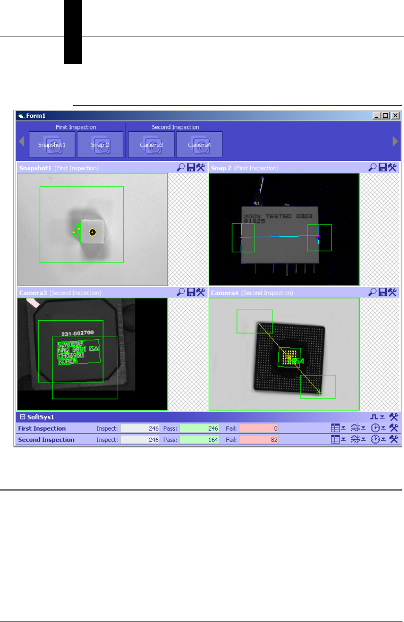
Chapter 4Viewing Images and Results w/VSRunView Control
4-10 Visionscape Programmer’s Kit (VSKit) Manual
FIGURE 4–7. After Compile and Run
Other Features of VsRunKit
In its simplest form, VsRunKit can be used with just one line of code (the
AttachDevice call). But, there are various other properties and methods of
the control that you can use to customize its appearance and behavior to
better suit your needs.

Other Features of VsRunKit
Viewing Images and
Results w/VSRunView
4
Visionscape Programmer’s Kit (VSKit) Manual 4-11
Showing and Hiding the Various Control Areas
You may decide that you only want to use VsRunView to display images,
and nothing else. You might decide to use the OpenAllSnaps method to
show all the snapshots and, therefore, you want to hide the Snap Buttons
so that the user can’t turn off the display of any of them. You may decide
that you want to display only the uploaded results. All of this is possible
because VsRunView allows you to show or hide the various control areas
using the following properties.
Property ShowDeviceViews As Boolean
Default = TRUE, set to False to hide the Device views at
the bottom of the control. This hides all reports and
counter information.
Property ShowSnapButtons As Boolean
Default = TRUE, set to False to hide the Snap Button toolbar
at the top of the control
Property ShowSnapViews As Boolean
Default = TRUE, set to False to hide the Snap View area
Property ShowConnectionInfo As Boolean
Default = FALSE, set to True to show a grid which
provides information on the various report connections
created by VsRunView
Handling Reports Yourself
Although VsRunView is capable of receiving and displaying the reports
from each of the running inspections, there are many instances in which a
programmer would want to have access to those reports. You can
configure VsRunView to raise an event whenever a report is received,
and to pass that report to your application. You must set the
ReportEventEnabled property to True in order to receive this event.
Property ReportEventEnabled As Boolean
With the ReportEventEnabled property set to True, you will now receive
the following event whenever reports are received:
Event OnNewReport(nInspIndex As Integer, rptObj As AvpInspReport, InspNameNode
As VsNameNode)
nInspIndex: This is the 1 based index of the inspection that generated the event.
rptObj: This is the uploaded AvpInspReport object which contains the inspection statistics

Chapter 4Viewing Images and Results w/VSRunView Control
4-12 Visionscape Programmer’s Kit (VSKit) Manual
(in the Stats property) and the uploaded results (in the Results property).
InspNameNode: A VsNameNode object which describes the inspection step that
generated the report.
The following is an example of how you might handle the OnNewReport
event in your code. Let's assume we modified our Simple Sample code to
set the ReportEventEnabled property to True in Form_Load:
'assume our VsRunView control is named ctlRunView
Private Sub ctlRunView_OnNewReport(nInspIndex As Integer,_ rptObj As
AVPREPORTLib.IAvpInspReport, InspNameNode As _ VSOBJLib.IVsNameNode)
Dim value As Variant
Dim res As AvpInspDataRecord
'VsNameNode provides the name of the inspection
Debug.Print "Name of this Inspection is " & _
InspNameNode.UserName
'if first inspection, get the number of blobs
If nInspIndex = 1 Then
'loop through all the results...
For Each res In rptObj.Results
'check the symbolic name for the
'one containing the Number of Blobs
If res.NameSym = "Snapshot1.Blob1.NumBlobs" Then
If res.value >= 2 Then
Debug.Print "Insp 1: Good Part"
Else
Debug.Print "Insp 1: Bad Part"
End If
Exit For 'found it, exit loop
End If
Next
ElseIf nInspIndex = 2 Then '2nd inspection
'search for the first 'Status' result
For Each res In rptObj.Results
If res.Type = "Datum.Status.1" Then
'found it, check value for Pass or Fail
If res.value = True Then
Debug.Print "Insp 2: Good Part"
Else
Debug.Print "Insp 2: Bad Part"
End If
Exit For
End If
Next

Other Features of VsRunKit
Viewing Images and
Results w/VSRunView
4
Visionscape Programmer’s Kit (VSKit) Manual 4-13
End If
End Sub
For more information on the AvpInspReport object, refer to Chapter 6,
“ Using Report Connections”.
Opening all the Snapshot Views
We covered this in our example. You would call the OpenAllSnaps
method to accomplish this. There is also a CloseAllSnaps method.
• Sub OpenAllSnaps()
Opens a snap view for every snapshot found on the device. This
should be called after you call AttachDevice.
• Sub CloseAllSnaps()
Closes all the currently open snapshot views.
Modifying the Image Layout
By default, all snapshots will be displayed in a grid. You can change this
however, with the following property:
• Property SnapViewLayout As SNAPVIEW_LAYOUT_STYLES
This property specifies how the various snapshot views will be
positioned when you are displaying more than one. The options are:
– SNAPVIEW_HORIZONTAL — Line up the images horizontally
– SNAPVIEW_VERTICAL — Line up the images vertically.
– SNAPVIEW_TILE — Arrange the images in a grid.
Using our earlier example, if we added the following line of code to
Form_Load():
ctlRunView.SnapViewLayout = SNAPVIEW_VERTICAL
then, our four images would be lined up vertically from top to bottom.

Chapter 4Viewing Images and Results w/VSRunView Control
4-14 Visionscape Programmer’s Kit (VSKit) Manual
Automatically Saving and Restoring the Control Settings
When creating a user interface, a common programming task is to insure
that the user’s configuration is saved when the application is shut down,
and then restored the next time it’s started. This can often be a tedious
task. VsRunView can take care of this for you by automatically saving and
restoring its state. To enable this feature, simply call the
EnableSaveSettings method:
Sub EnableSaveSettings(strAppName As String, [bUseXml As Boolean = False])
strAppName: This specifies the registry path to the key your application is currently using
to save its settings.
bUseXml: Currently not supported, should be left at the default setting of False.
This method will create a key in HKEY_CURRENT_USER named
VsRunView, under the key you specified in the strAppName parameter.
VsRunView will then save all of its settings under this key. The following
example shows how FrontRunner uses this parameter:
'm_run is the name of the VsRunView control
m_run.EnableSaveSettings
“Software\Visionscape\FrontRunner”
The above line of code causes VsRunView to create a VsRunView key in
the registry under HKCU\Software\Visionscape\FrontRunner. All settings
are saved and restored from this key. You must make sure to call
EnableSaveSettings before you call AttachDevice. Settings are saved
when DetachDevice is called, and read when AttachDevice is called.
Logging Results to File
VsRunView makes it easy to log your results to a text file. Simply call
either the LogStart method, or the LogStartAll method, with the proper
parameters, and your results will be logged to disk for you. Call either
LogStop or LogStopAll when you wish to shut logging off.
• Function LogStartAll(strBasePath As String, LogOpts As
AvpLogOptions) As Boolean
– strBasePath — The full path, including the base file name, you
want your results to be saved to.

Other Features of VsRunKit
Viewing Images and
Results w/VSRunView
4
Visionscape Programmer’s Kit (VSKit) Manual 4-15
– LogOpts — A reference to an AvpLogOptions object that
specifies how you want your results to be formatted.
This method turns on result logging for all inspections currently
running. The set of results that were selected for upload for each
inspection will be logged to separate files. If there is only one
inspection, then the exact file name specified by the strBasePath
parameter is used. If there is more than one inspection, then the
device name and the symbolic name of the inspection are appended
to the file name to insure uniqueness. For example, if you specified
the following path:
C:\Vscape\Jobs\Logfile.txt
and you were running two inspections (symbolic names “Insp1” and
“Insp2”) on the device name “0740_01”, then you would get two
separate log files named:
C:\Vscape\Jobs\Logfile_0740_01_Insp1.txt
C:\Vscape\Jobs\Logfile_0740_01_Insp2.txt
The LogOpts parameter is of type AvpLogOptions, which is a special
object that specifies the formatting options that will be applied when
writing your results to the text file. The properties of this object follow.
AvpLogOptions
• Property AppendToFile As Boolean
If the specified log file already exists, and this property is set to True,
then new data will be appended to the file. The default is False, which
means the existing file will be overwritten.
• Property Delimiter As String
The string that separates data in the file. This is set to the TAB
character by default, but you may specify any character or string of
characters you wish.
• Property IncludeNames As Boolean
– True — The result names are logged to disk along with the data
– False — (Default) Only the data will be logged

Chapter 4Viewing Images and Results w/VSRunView Control
4-16 Visionscape Programmer’s Kit (VSKit) Manual
• Property PrefixOptions As tagLOG_ADDIN_OPTIONS
Property SuffixOptions As tagLOG_ADDIN_OPTIONS
Use these options to specify different types of data you want included
in the Prefix or the Suffix of each cycle’s data. The enum values may
be added together so that you can include more than one value. The
options are:
– ADDIN_DATE — Includes the current date.
– ADDIN_TIME — Includes the time when each value is written.
– ADDIN_COUNT_INSPECTED — Includes the inspected count.
– ADDIN_COUNT_PASSED — Includes the passed count.
– ADDIN_COUNT_REJECTED — Includes the rejected count.
– ADDIN_INSPECTION_STATUS — Includes the Inspection's
Pass/Fail status
– ADDIN_INSPECTION_STEP_NAME — Includes the Inspections
user assigned name.
– ADDIN_NONE — Default. Include no data.
• Property PrefixString As String
Property SuffixString As String
A user assigned string that will be added to the prefix or suffix of each
cycle’s data.
• Property SaveMode As tagLOG_SAVE_MODE
– LOG_SAVE_ALL — Save all reports to disk.
– LOG_SAVE_FAILED — Save only data from failed inspections.
– LOG_SAVE_PASSED — Save only data from passed
inspections.
• Property TerminateOption As tagLOG_TERMINATE_OPT
Determines when the Terminator string (CRLF by default) is
appended to the result string each cycle. The options are:

Other Features of VsRunKit
Viewing Images and
Results w/VSRunView
4
Visionscape Programmer’s Kit (VSKit) Manual 4-17
– TERMINATE_AFTER_EACH_RESULT — (Default) Append the
terminator after each result. The data from each cycle is easier to
view in the text file with this option, but will be harder to analyze in
a spreadsheet if that is your goal.
– TERMINATE_AT_END_OF_ALL_RESULTS — Terminator is only
appended at the end of all results. If you are logging data with the
plan of importing that data into a spread sheet for analysis, this is
generally the option you would want to choose.
• Property Terminator As String
By default, CR & LF is used as the terminator. Where the terminator is
appended within the string depends on the setting in
TerminateOption. You may enter any character or combination of
characters to use as the Terminator string.
Look and Feel Features
The following are a few other useful properties and methods of
VsRunView:
• Property ZoomMode As SNAPVIEW_ZOOM_MODES
VsRunView will always automatically zoom the images to fit into their
respective snapshot views. The user does have options to allow them
to zoom in or out on any one of the images however. This property
controls how zooming is handled:
– SNAPVIEW_ZOOM_MAXIMIZE — This is the default. When the
user selects the zoom option on the toolbar for a particular image,
that image is maximized to fill the snap view area of the control.
Then, you can zoom in or out as you wish for that image.
– SNAPVIEW_ZOOM_INPLACE — Allows the user to zoom in or
out on any of the snapshot views in place. In other words, with
this option selected, the snapshot view will not become
maximized when zooming.
– SNAPVIEW_ZOOM_DISABLED — Prevents the user from
zooming entirely.
• Property ResultUseWorld As Boolean

Chapter 4Viewing Images and Results w/VSRunView Control
4-18 Visionscape Programmer’s Kit (VSKit) Manual
If you have calibrated your inspections, and want VsRunView to
display uploaded results in world units (inches, mm, etc), then set this
property to True.
• Sub ResultPrecisionSet(nNumDecimalPlaces As Integer)
Specifies the number of decimal places used when displaying floating
point values in the report.
• Property ReportViewSizePerCent As Long
Specifies the percentage of the control area that should be used to
display the report view. Note that this only applies when the report
view is opened, and not when the user has collapsed it.
• Sub OpenSnapView(nnSnap As VsNameNode, [hIndex As Integer =
1])
Public Sub CloseSnapView(nnSnap As VsNameNode)
These methods open or close a specific snapshot view. In each case,
you must specify the VsNameNode of the snapshot whose view you
want to open/close. Typically, you will use the VsDevice object's
ListSnapshots method (along with its ListInspections method) to get a
list of available snapshots as VsNameNode references. Refer to
“Namespace Information” on page 3-21 for more information on the
Namespace and VsNameNodes.
• Property MaxSnapViews As Long
Allows you to specify the maximum number of snapshot views that
can be displayed at one time. If you set this to 2, and the user has 2
snap views selected, and then tries to select a third, the new
snapshot selection will be added, and the oldest selection will be
removed.

Visionscape Programmer’s Kit (VSKit) Manual 5-1
5
Using VsKit
Components
5
CHAPTER 5 Using VsKit Components
Visionscape Control Toolkit
The Visionscape Control Toolkit (VsKit.ocx) was introduced with Version
3.6, and its purpose is to allow the creation of simple user interfaces with
very little programming. Most user interfaces are created to provide
custom runtime functionality, and that’s why we created the VsRunView
control for Version 3.7. VsRunView is generally more powerful and the
better choice for most applications, but there are many instances in which
the VsKit components can provide you with the functionality you are
looking for. By way of introduction, we will start with a simple application;
it will take only a few minutes to try and will serve to illustrate just how
powerful the VsKit framework is.
A Simple Application
There are many ways in which you can select a focus device; there are a
couple of VsKit controls that make this very straightforward. Because of
the concept of device focus, controls will automatically coordinate with
each other without much additional work on the part of the programmer
The following example demonstrates how to make a simple monitoring
application using the controls in VsKit. You don’t even have to write ANY
code to make this work!
Start by creating a new Visual Basic project, go to the Project menu, and
select “Components…”, and then select the following library:
+Visionscape Controls: VsKit
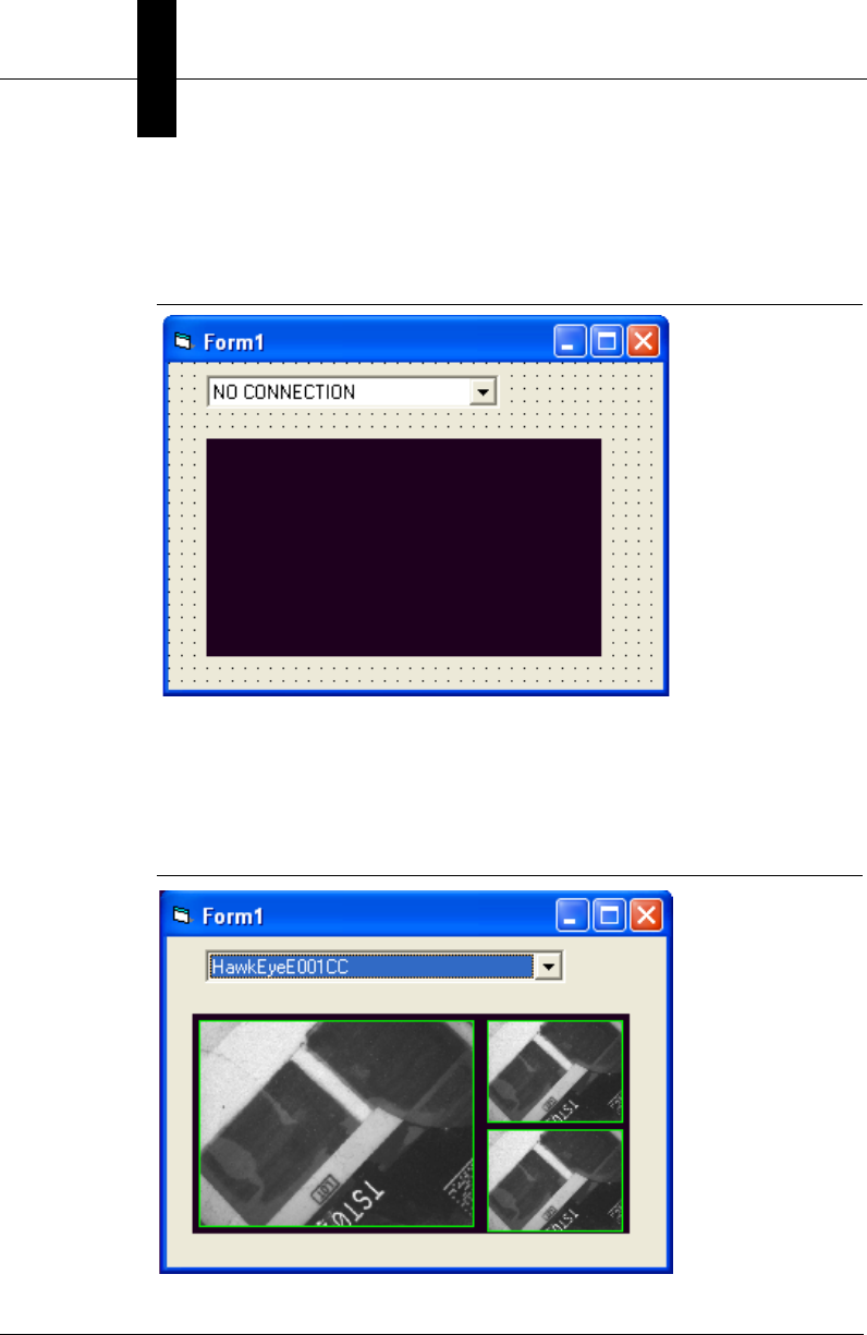
Chapter 5Using VsKit Components
5-2 Visionscape Programmer’s Kit (VSKit) Manual
On your applications main form, place a VsDeviceDropdown control and
a VSFilmstrip control. Your form should look like this:
FIGURE 5–1. Your Form Should Look Like This
Believe it or not, that’s all it takes to make a functioning application. Now,
if you run the project, you can select a device from the
VsDeviceDropdown control (be sure to select a device that is running),
and you will see an image display from that camera in the VsFilmstrip.
FIGURE 5–2. Image Display

Visionscape Control Toolkit
Using VsKit
Components
5
Visionscape Programmer’s Kit (VSKit) Manual 5-3
VsCoordinator is the magic that makes this work. The
VsDeviceDropdown uses the VsCoordinator to fill its list, and when one is
selected, the DeviceFocusSet method is called. In turn, this causes the
OnDeviceFocus event to be fired for all “instances” of the VsCoordinator,
including the one in VsFilmstrip. The default behavior of VsFilmstrip is to
make an image connection and display images in filmstrip style. There
are options that allow you to change this behavior, if desired (see
“VsFilmstrip” on page 5-6).
VsDeviceDropdown
The VsDeviceDropdown control is a very easy way to select a device. By
default, the drop-down list will contain all known devices and will update if
any new ones are discovered on the network. When a device is selected
from the drop-down list, the default behavior is to call SetDeviceFocus on
the selected device, which will, in turn, cause the OnDeviceFocus event
to be raised for every “instance” of a VsCoordinator. Most of the controls
in the Control Toolkit handle the OnDeviceFocus event and then
automatically perform their function on the selected device. In the
previous simple example, the selection of a device automatically allowed
the VsFilmstrip control to create an image connection and begin to
display the received images.
OnFilterDevice Event
You can filter the devices shown in the drop-down list by handling the
OnFilterDevice event. For example, a useful improvement to the previous
example would be to filter the list of devices that are displayed in the
VsDeviceDropdown control so that only running network devices are
shown. You can easily accomplish this by handling the OnFilterDevice
event from the VsDeviceDropdown control:
Private Sub VsDeviceDropdown1_OnFilterDevice(dev As VSOBJLib.IVsDevice, bShow
As Boolean)
bShow = (dev.DeviceClass = DEVCLASS_SMART_CAMERA) _
And (dev.DeviceState = DEVSTATE_RUNNING)
End Sub
The OnFilterDevice event is sent for each item before it’s put into the
drop-down list. Set the bShow Boolean to True if you want the device to
show in the list; set it to False otherwise. The sample above filters out all
devices that are not smart cameras and are not running.

Chapter 5Using VsKit Components
5-4 Visionscape Programmer’s Kit (VSKit) Manual
OnDeviceSelected Event
Whenever a device is selected in the VsDeviceDropdown control, the
OnDeviceSelected event is raised. Normally, it would not be necessary to
handle this event, because OnDeviceFocus would also be raised and any
logic relevant to the device selection would go there. However, setting
AutoConnect to False disables the call to SetDeviceFocus, so your only
event would be OnDeviceSelected.
OnSelectedDeviceLost Event
If the device currently selected in the VsDeviceDropdown control
becomes uncommunicative, the OnSelectedDeviceLost event is raised
and the drop-down control will reflect that no device is currently selected.
AutoConnect Property
You can override the default Device Focus behavior by setting the
AutoConnect property of VsDeviceDropdown to False. This is a persistent
property so, if you want to turn it off, we recommend you do so using the
Properties Window from Visual Basic rather than using explicit code.
Once AutoConnect is set to False, the Device Focus will not change when
you select a new device and, therefore, you will need to handle the
OnDeviceSelected Event yourself.
Device Property
The currently selected device is available by using the Device property.
Be sure to check against the case where nothing is selected, as in the
following code:
Dim dev As VsDevice
Set dev = VsDeviceDropdown1.Device
If (Not dev Is Nothing) Then
' do something with dev
End If
GroupID Property
The GroupID comes into play in situations where you need more than one
Focus Device. For example, let’s expand the simple application example
by allowing two different devices to be viewed at once.
Just as in the previous example, start by creating a new Visual Basic
project and add the Visionscape Control Toolkit as a component. This
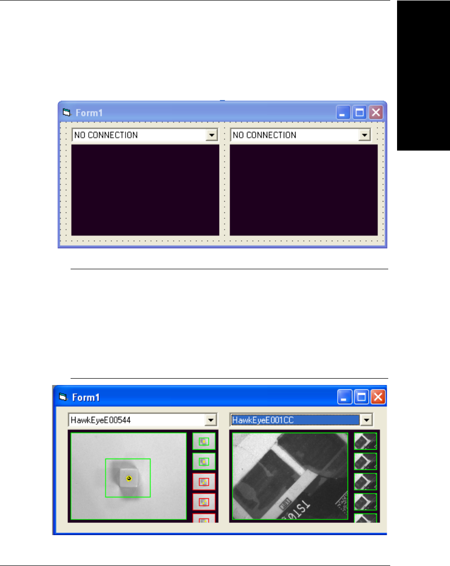
Visionscape Control Toolkit
Using VsKit
Components
5
Visionscape Programmer’s Kit (VSKit) Manual 5-5
time, place two VsDeviceDropdown controls and two VSFilmstrip controls
on the form. Your form should look like this:
FIGURE 5–3. 2 VsDeviceDropdown Controls and 2 VSFilmstrip
Controls
Now, change the GroupID property of both the VsDeviceDropdown and
VsFilmstrip controls on the left hand side to 1, and the GroupID properties
for the right hand controls to 2. The value you use for GroupID doesn’t
matter, except that they must agree and the value -1 is reserved for the
default case. Running the application now shows that the control sets
work independently:
FIGURE 5–4. Controls Sets Work Independently
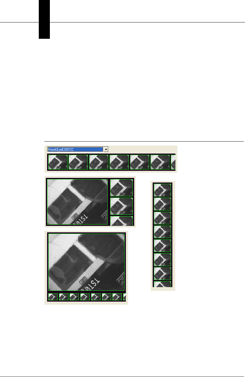
Chapter 5Using VsKit Components
5-6 Visionscape Programmer’s Kit (VSKit) Manual
VsFilmstrip
The VsFilmstrip control allows the display of images with graphics, and
can include an optional bounding rectangle representing pass/fall status.
As was demonstrated in the previous examples, by default, it handles the
OnDeviceFocus event and makes a report connection requesting and
displaying the output images from the first inspection. Also by default, it
displays a history of images in filmstrip style. The arrangement of the
filmstrip depends on the dimensions of the control; the images are
automatically arranged for optimum fit. Some examples:
FIGURE 5–5. VSFilmStrip Arrangement for Optimum Fit
FilmstripMode Property
By setting FilmstripMode to False, the VsFilmstrip control will only display
the most current image and not attempt to show previous images in the
filmstrip style:
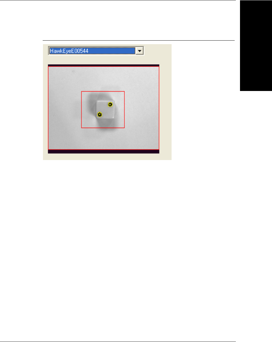
Visionscape Control Toolkit
Using VsKit
Components
5
Visionscape Programmer’s Kit (VSKit) Manual 5-7
FIGURE 5–6. Most Current Image
AutoConnectInspection and AutoConnectBuffer Properties
By default, VsFilmstrip is in AutoConnect mode and will attempt to
connect and display images from the first snapshot in the first inspection.
Using symbolic names, this is referred to in the step framework as
Insp1.Snapshot1.BufOut. You can select a different inspection or buffer to
display by changing the AutoConnectInspection and AutoConnectBuffer
properties. For example, to auto connect to the second snapshot of
inspection 2:
VsFilmstrip1.AutoConnectInspection = "Insp2"
VsFilmstrip1.AutoConnectBuffer = "Snapshot2.BufOut"
AutoConnect Property
You can turn off the AutoConnect behavior by setting AutoConnect to
False. This will disable any automatic behavior of VsFilmstrip, allowing
you to use the control to display any set of buffers you wish by using the
NewBufferDm method described next.
NewBufferDm Method
If AutoConnect is set to False, you must manually tell the VsFilmstrip
control which buffers to display by calling the NewBufferDm method. The
API is:

Chapter 5Using VsKit Components
5-8 Visionscape Programmer’s Kit (VSKit) Manual
Public Sub NewBufferDm(ByVal buf As IBufferDm, ByVal bPassed As Boolean)
There are a number of ways to obtain a BufferDm, either from a file or
from an inspection report, but assuming you have a BufferDm named buf,
you would add it to the VsFilmstrip display:
VsFilmstrip1.NewBufferDm buf, bInspectionPassed
The second parameter determines whether to draw a Red (Failed) or
Green (Passed) rectangle around the image.
Clear Method
To clear all of the displayed images in the VsFilmstrip control, call the
Clear method:
VsFilmstrip1.Clear
GroupID Property
The VsFilmstrip supports the GroupID property, as do most controls in
VsKit. Refer to the GroupID section (see “Grouping Controls Using
GroupID” on page 3-29) for VsDeviceDropdown for a more detailed
description.
OnNewReport Event — Sharing the AutoConnect Report
Connection
If you use VsFilmstrip in its AutoConnect default manner, it will make a
report connection. You can use this already made connection if you want,
because every time a new report comes in, the VsFilmstrip will raises the
OnNewReport event. Therefore, you can use this event to retrieve any
other information from the inspection report.
VsReportConnection
The Visionscape AvpReport Type Library contains objects to make report
connections to a device and interpret the InspectionReports that result.
VsKit contains an object called VsReportConnection that simplifies the
use of connections to a large extent, without sacrificing much in the way
of capability.
Note: Even if you use VsReportConnection instead of the lower level
objects, you will still have to add the AvpReport Type Library as a

Visionscape Control Toolkit
Using VsKit
Components
5
Visionscape Programmer’s Kit (VSKit) Manual 5-9
reference to your project to gain access to the data type definitions
contained there.
The following simple example will illustrate the basic method of using
VsReportConnection. Starting with a new Standard EXE, make sure the
following are included in the Project settings:
Components:
Acuity Visionscape Control Toolkit (VSKIT.OCX)
References:
Acuity Visionscape Device Objects (VSOBJ.DLL)
Acuity Visionscape AvpReport Library (AVPREPORT.DLL)
We will use a VsDeviceDropdown as a way of selecting a device, so the
following code assumes that one has been placed on the main form.
Instead of using Device Focus, we will simply handle the
OnDeviceSelected event from VsDeviceDropdown1 to make a
connection when a device is selected using the drop-down. The
VsConnectionObject is declared WithEvents, so we can handle the
OnNewReport event to retrieve the InspectionReports. The example
simply prints the CycleCount to the Visual Basic debug window:
Dim WithEvents m_conn As VsReportConnection
Private Sub Form_Load()
Set m_conn = New VsReportConnection
End Sub
Private Sub m_conn_OnNewReport(ByVal rptObj As AVPREPORTLib.IAvpInspReport)
Debug.Print rptObj.Stats.CycleCount
End Sub
Private Sub VsDeviceDropdown1_OnDeviceSelected(dev As VSOBJLib.IVsDevice)
m_conn.Connect dev
End Sub
As you can see, the basic mechanism is quite easy to use. The call to
m_conn.Connect in the OnDeviceSelected event is being used with all
other parameters defaulted. The default behavior is to connect to the first
inspection, and to only retrieve the basic statistics. If the device passed to
Connect is Nothing, then the call functions as a Disconnect, so no explicit
logic is necessary to handle the case where NO CONNECTION is
selected in the VsDropdown control.

Chapter 5Using VsKit Components
5-10 Visionscape Programmer’s Kit (VSKit) Manual
Connect Method
To establish a connection, simply call the Connect method. The API for
this call is:
Function Connect(Device As VsDevice, _
[bIncludeFullReport As Boolean = False], _
[inspPath As String = "Insp1"], _
[imgPath As String]) As Boolean
• Device — (Required) The VsDevice you want to connect to. If this
parameter is Nothing, a Disconnect will occur.
• bIncludeFullReport — By default, only retrieve inspection statistics. If
you want the compete inspection report, including all results tagged
for upload, then set this parameter to True
• inspPath — The symbolic name of the inspection to connect to. By
default, this will be the first inspection.
• imgPath — The symbolic name of an image to add to the report. Set
this to the path of the BufferDm representing the output of the
inspection. See the following example for more detail.
IsConnected Property
You can check if the VsConnection object has an active connection by
checking the IsConnected property:
If m_conn.IsConnected then
' Do Something
End If
Disconnect Method
You can disconnect simply by calling the Disconnect method. This will not
cause an error if you are already disconnected. Alternatively, you can call
Connect with Nothing specified for the device; this will be treated as the
equivalent to Disconnect:
' two ways of disconnecting
m_conn.Disconnect
m_conn.Connect Nothing

Visionscape Control Toolkit
Using VsKit
Components
5
Visionscape Programmer’s Kit (VSKit) Manual 5-11
Image Connections
It’s important to understand that in the current Visionscape programming
framework, there is no distinction between an Image connection and a
normal Report connection. Earlier versions of the framework had this
distinction. To create the equivalent of an Image connection, you must
add the desired image buffer path to the report. The following Connect
call creates a typical image connection:
m_iconn.Connect m_device, False, "Insp1", "Snapshot1.BufOut"
This example retrieves the output buffer of the first snapshot of the first
inspection. Because the second parameter is set to False, only the image
is received, leaving out any other data that might have been tagged for
upload in the inspection. (The Inspection Stats are ALWAYS sent,
regardless, so the resulting report will always have those fields available.)
DropWhenBusy Property
By default, a VsReportConnection will drop (not send) a report if the PC is
busy. This behavior prevents the target vision system from waiting for the
PC to process each record before a new one is sent. This can cause a
significant performance impact depending on the application. However,
there are situations where every report is required, and the PC inspection
report processing time is acceptable. To retrieve every inspection report,
set the DropWhenBusy property to False:
' make a lossless connection
m_conn.DropWhenBusy = False
GraphicsOn Property
By default, when images are received, graphics are not included with the
image. To enable graphics, set the GraphicsOn property to True:
' get graphics
m_conn.GraphicsOn = True
Chapter 5Using VsKit Components
5-12 Visionscape Programmer’s Kit (VSKit) Manual
MaxRate Property
When a connection is in the DropWhenBusy mode, the MaxRate can be
set to limit the number of records sent. The value can be one of the
following:
ExcludeImages Property
Although the most common scenario is to establish an image connect as
described above, it’s possible to have images also included with an
inspection report if the job has been configured to do so. In this event, it
may be desired to exclude the images already tagged for upload, but still
get the rest of the result data. To exclude from the report any images that
are tagged for upload in the job, set the ExcludeImages property to True:
' don't bother sending images tagged for upload in the Job
m_conn.ExcludeImages = True
FreezeMode Property
By default, a connection will send all reports (perhaps dropping some if
DropWhenBusy is True). The FreezeMode property allows some filtering
on the reports returned. The values for FreezeMode are defined in
Table 5–2:
Note: REQUIRES reference to Visionscape Basic Report Type Library
(VSREPORT.DLL).
TABLE 5–1. MaxRate Value
Value Meaning
-1 Every report will be sent. This setting may affect the inspection rate.
0 Maximum Rate without slowing down inspection. If necessary
reports will be dropped.
N>0 Maximum rate specified in reports per second. For example, if the
value is 2, then you will at most receive 2 reports every second. All
other reports will be dropped.

Visionscape Control Toolkit
Using VsKit
Components
5
Visionscape Programmer’s Kit (VSKit) Manual 5-13
DataRecordAdd Method
It’s possible to add any datum to an inspection report, even if that datum
has not been tagged for upload in the inspection. In fact, this is how
image connections are made; the snapshot output buffer is simply added
to the inspection report. For example, the image connection discussed
previously could have been accomplished by the following, but this time
we'll ask for two buffers to be added:
' an alternate way of making an image connection
m_iconn.Connect m_device, False, "Insp1"
m_conn.DataRecordAdd "Snapshot1.BufOut"
m_conn.DataRecordAdd "Snapshot2.BufOut"
Notice that the symbolic paths used are relative to the inspection
specified in the Connect call.
This mechanism is not limited to image buffers, so any Datum value can
be explicitly requested even if the Inspection was not originally set up to
have the Datum in the Tagged for Upload list.
VsFileUtilities
The VsFileUtilities control performs many useful functions; they include,
but are not limited to, opening and saving job files. Unlike other VsKit
controls, there is no user interface element to this control; it will not be
visible on a form during runtime. There are great benefits to using this
TABLE 5–2. FreezeMode Values
RFRZ_SHOW_ALL 0 Get All Reports
RFRZ_SHOW_FAILED 1 Only Reports that represent Inspection Failures
RFRZ_FREEZE_THIS 2 Freeze the Current Report until a new FreezeMode is
set
RFRZ_FREEZE_NEXT_FAILED 3 Send a report on the next failed inspection, and then
Freeze
RFRZ_FREEZE_LAST_FAILED 4 Send the Last Inspection that Failed, then Freeze,
even if new failures come along
RFRZ_FREEZE_NEXT_QUAL 5 Freeze on next report that matches Qualifier set in the
inspection step.

Chapter 5Using VsKit Components
5-14 Visionscape Programmer’s Kit (VSKit) Manual
control vs. trying to write the entire equivalent functionally yourself, but,
there is one very important caveat:
Note: There must only be a single VsFileUtilities object in your project. If
you have multiple forms or controls that use it, place the control on ONE
FORM ONLY. The only exception is if you have different GroupIDs
assigned to each one. Even with a single control, you can still use the
functionality of VSFileUtilities from anywhere in your project.
Unlike most controls, you do not call specific APIs to perform the
functions in VsFileUtilities. Instead, the calls are made using symbolic
names representing the function to perform. This enables you to connect
a toolbar or buttons very easily. For example, you can use the Key or Tag
fields of each button on a toolbar to hold the function name representing
that button. Then, a short generic piece of code can link your toolbar to all
the functions in VsFileUtilities. The functions are implemented using the
VsFunctions mechanism (see “Using VsFunctions to Synchronize UI
Elements” on page 3-34), so you may want to review that section if you
want to manually invoke any of these functions or do something a bit out
of the ordinary. Table 5–3 contains all the functions defined in
VsFileUtilities:
TABLE 5–3. VSFunctions Implemented by VSFileUtilities
VsFunction Name Action
Close Close the current Job
DumpAsText Dump the current Job as a text file
Flash Write the Job on the current device to Non-Volatile Memory
JobInfo Show a Dialog with information about the current Job
New Create a new Job for the selected device (Focus Device).
Open Open an existing job for the selected device. If the job requires changes
to run on the selected device, a dialog will be shown to assist.
OpenAll Open a job that was created for multiple targets. If the job requires
changes to run on the selected devices, a dialog will be shown to assist.
OpenInsp Open a job consisting of a single inspection and merge it with the exiting
job.
ReleaseControl Release control of the selected device.
Save Save the current Job, ask for a file name if necessary.
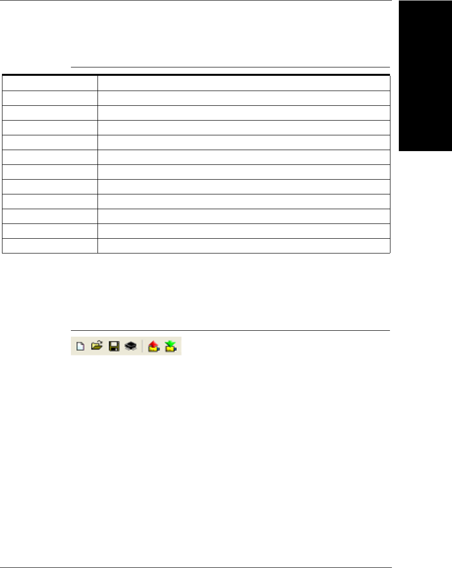
Visionscape Control Toolkit
Using VsKit
Components
5
Visionscape Programmer’s Kit (VSKit) Manual 5-15
Toolbar Example
As an example, let’s connect a toolbar to some of these functions. A
toolbar might have the following buttons:
FIGURE 5–7. Toolbar Buttons
From left to right, we will connect the buttons to the functions “New”,
“Open”, “Save”, “Flash”, “ToPC” and “ToDevice”.
The goal is to connect each button to the corresponding function, and
disable the button when it’s not appropriate for it to be enabled.
We start by using the Key field of each toolbar button to define the
function to call. For example, the first button (“New”) in the toolbar:
SaveAll Save the current Job.
SaveAs Save the current Job, always ask for a file name.
SaveInsp Save a single Inspection
Start Start all inspections on the selected device
StartAllBackplane Start all inspections on all vision accelerators (not smart cameras)
Stop Stop all inspections on the selected device
StopAllBackplane Stop all inspections on all vision accelerators (not smart cameras)
TakeControl Take control of the selected device. A login dialog will be displayed.
ToDevice Download a Job to the current device
ToDeviceAll Download a Job that includes multiple targets
ToPC Upload a Job from the current device
TABLE 5–3. VSFunctions Implemented by VSFileUtilities (continued)
VsFunction Name Action
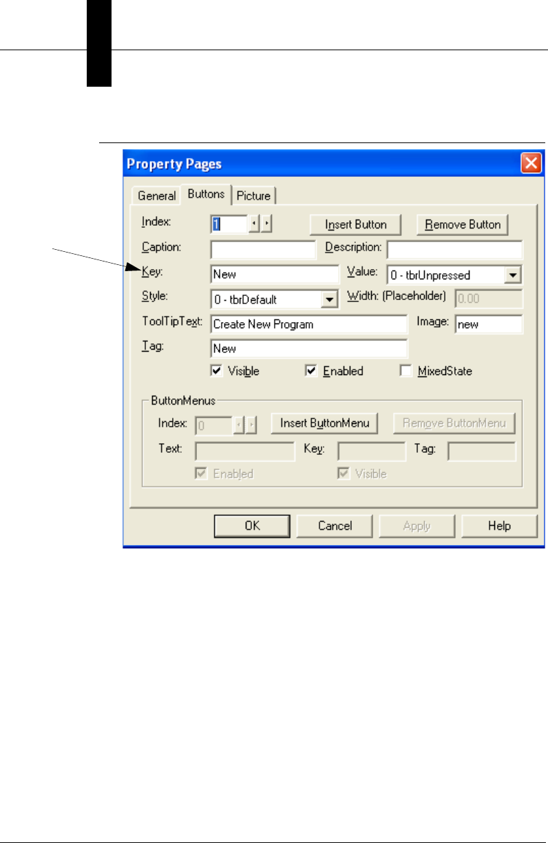
Chapter 5Using VsKit Components
5-16 Visionscape Programmer’s Kit (VSKit) Manual
FIGURE 5–8. New Button Defined
The entire button handler for the toolbar is:
Private Sub m_toolbar_ButtonClick(ByVal Button As MSComctlLib.Button)
m_coord.InvokeFunction Button.key
End Sub
Admit it - that was almost too easy.
Now, we have to write some code to enable or disable the buttons, as
appropriate. To do so, we need to handle the OnFunctionEvent event
from VsCoordinator. We will separate the code to enable the toolbar
buttons into a separate EnableToolbarButtons subroutine so that we can
also call it from Form_Load:
' We get this event whenever any of the VsFunctions change state.
Private Sub m_coord_OnFunctionEvent(ByVal ev As VSOBJLib.tagFNEVENTS, ByVal objFn As
VSOBJLib.IVsFunction)
If ev = FN_CHANGED Then
Key corresponds
to the VSFunction
Name

Visionscape Control Toolkit
Using VsKit
Components
5
Visionscape Programmer’s Kit (VSKit) Manual 5-17
EnableToolbarButtons
End If
End Sub
' This subroutine walks the list of buttons in the toolbar
' and uses the Key property of each button to determine
' whether to make visible, enable, or show as depressed.
Private Sub EnableToolbarButtons()
Dim fn As VsFunction
Dim but As MSComctlLib.Button
For Each but In m_toolbar.Buttons
If (but.Style <> tbrPlaceholder) Then
Set fn = m_coord.GetFunction(but.Key)
If Not fn Is Nothing Then
but.Visible = fn.Visible
but.Enabled = fn.Enabled
but.Value = IIf(fn.Highlight,
vbChecked, vbUnchecked)
Else
but.Visible = False
End If
End If
Next but
End Sub
Notice that the Visible, Enabled, and Value fields are set for each toolbar
button, making the button reflect the correct state of the function at all
times.
VsView
VsView is a very powerful control that contains much of the runtime and
editing functionality contained in FrontRunner. It should not be used for
applications that simply want to display an image, as the VsFilmstrip
control is designed for that purpose. However, if your goal is to create an
editing environment much like FrontRunner, the VsView control is
available for your use. In the same manner previously described for
VsFileUtilities, the VsView control implements most of its functionality
using the VsFunction mechanism, which makes it very straightforward to
connect toolbars and have them reflect the current operational state of
the selected device.
VsView automatically switches its view between editing and runtime
environments, depending on the device state. When there is job currently
being edited and the device is stopped, the view will appear similar to the
following:
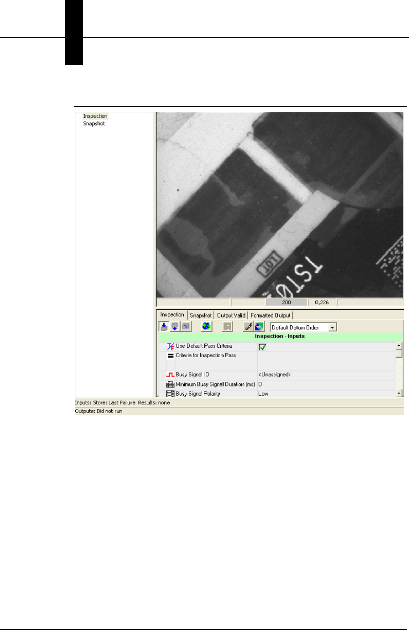
Chapter 5Using VsKit Components
5-18 Visionscape Programmer’s Kit (VSKit) Manual
FIGURE 5–9. VsView Editing Environment
When the device is running, VsView will automatically switch to the
runtime view:
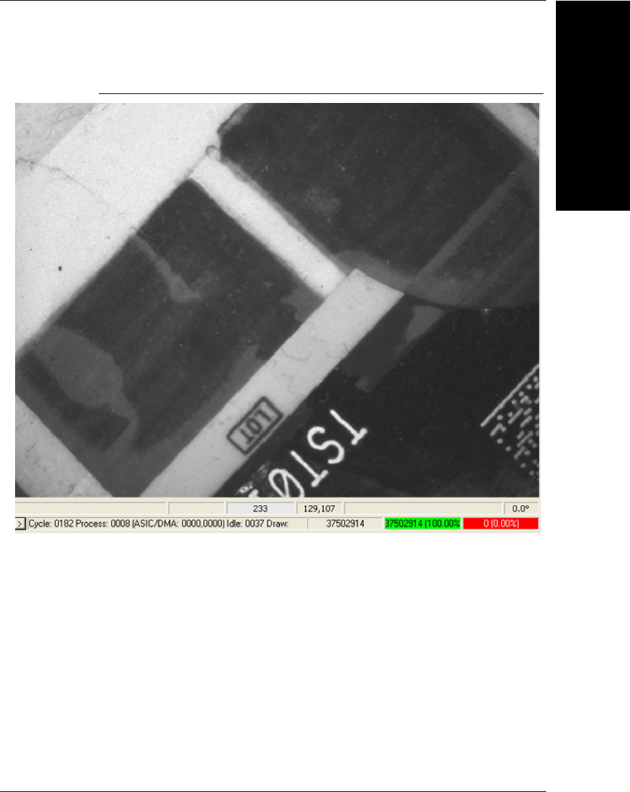
Visionscape Control Toolkit
Using VsKit
Components
5
Visionscape Programmer’s Kit (VSKit) Manual 5-19
FIGURE 5–10. VSView Runtime Environment
If you have used previous versions of the Visionscape framework, you will
recognize these views as representing SetupMgr and RuntimeMgr. Those
controls are still available if you need to use them directly; however, their
direct use is no longer recommended.

Chapter 5Using VsKit Components
5-20 Visionscape Programmer’s Kit (VSKit) Manual
TABLE 5–4. VSFunctions Implemented by VSView
VsFunction Name Action
Acquire Acquire a single image
AutoRun Automatically run tools when changed. Setting the function to 0
will disable AutoRun while setting to 1 will enable it.
AutoTrain Automatically train tools when relevant. Setting the function to
0 will disable AutoTrain while setting to 1 will enable it.
FreezeMode Enumerated Type: Images; Failed Images; Freeze This;
Freeze Next Failed; Freeze Last Failed
ImageRate The current Image Rate
LiveVideo Enter / Exit Live Video mode
OnStepInserted A special function that is invoked when a new step has been
inserted
Pause Pause Tryout (only valid in tryout mode).
PropertiesOption
ReportLogDirectory
ReportLogFilter
ReportLogFormat
ReportLogGraphics
SaveCurrentImage Save the currently displayed image to disk.
SelectInsp The index of the currently selected Inspection
SelectSnap The index of the currently selected Snapshot
SelectStep Stores the handle to the selected step
ShowMaskTools Display the Masking Tools Dialog
ShowRuntimeDeviceGraphics Relevant only for vision accelerators with built in VGA displays.
Enable / Disable graphics display on the device's VGA display.
Setting the function to 0 will show no graphics while setting to 1
will display graphics.
ShowRuntimeDeviceImage Relevant only for vision accelerators with built in VGA displays.
Enable / Disable image display on the device's VGA display.
Setting the function to 0 will show no images while setting to 1
will display images.

Visionscape Control Toolkit
Using VsKit
Components
5
Visionscape Programmer’s Kit (VSKit) Manual 5-21
ShowRuntimeDeviceReport Relevant only for vision accelerators with built in VGA displays.
Enable / Disable report display on the device's VGA display.
Setting the function to 0 will show no report while setting to 1
will display the report
ShowRuntimePCGraphics Enable / Disable graphics display within VsView. Setting the
function to 0 will show no graphics while setting to 1 will display
graphics.
ShowRuntimePCImage Enable / Disable image display within VsView. Setting the
function to 0 will show no images while setting to 1 will display
images.
ShowSettings Display the settings dialog
ShowThreshDlg Display the Threshold Setting Dialog
StartAll Start All Inspections on the selected device
StopAll Stop All Inspections on the selected device
TimingEnable
TimingReset
Train Train the current step (if Trainable)
TrainNeed Reflects the train status - a button tied to this VsFunction will
be visible only if a trainable tool has not been trained.
Tryout Enter Tryout Mode
TryoutAcquire Acquire images while in tryout. Setting the function to 0 will
disable TryoutAcquire while setting to 1 will enable it.
TryoutCurrent Tryout the Current Step
TryoutOnce Tryout Once
TryoutUseDelay Enables a small delay between steps during tryout. Setting the
function to 0 will disable TryoutUseDelay while setting to 1 will
enable it.
TryoutUseIO Use IO while in tryout. Setting the function to 0 will disable
TryoutUseIO while setting to 1 will enable it.
TryoutUseTrigger Obey triggers while in tryout. Setting the function to 0 will
disable TryoutUseTrigger while setting to 1 will enable it.
Untrain Untrain the current step (if Untrainable)
WizDown Step to the next step in the setup list
WizUp Step to the previous step in the setup list
TABLE 5–4. VSFunctions Implemented by VSView (continued)
VsFunction Name Action
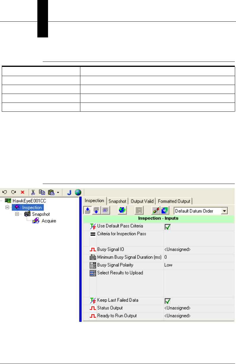
Chapter 5Using VsKit Components
5-22 Visionscape Programmer’s Kit (VSKit) Manual
VsTreeBrowser
The VsTreeBrowser is the same control used by FrontRunner to allow
editing of the Job step tree. It will automatically function if the
VsCoordinator.Job and VsDevice.ProgramController properties are set
correctly, as described in the detailed sections describing those objects.
You can use it in your own application simply by including it on a form.
FIGURE 5–11. VsTreeBrowser — Editing of Job Tree
ZoomAuto Scale the displayed image to best fit the display area.
ZoomIn Zoom In on the displayed image
ZoomOne Set the Zoom Magnification to 1:1
ZoomOut Zoom Out on the displayed image
TABLE 5–4. VSFunctions Implemented by VSView (continued)
VsFunction Name Action
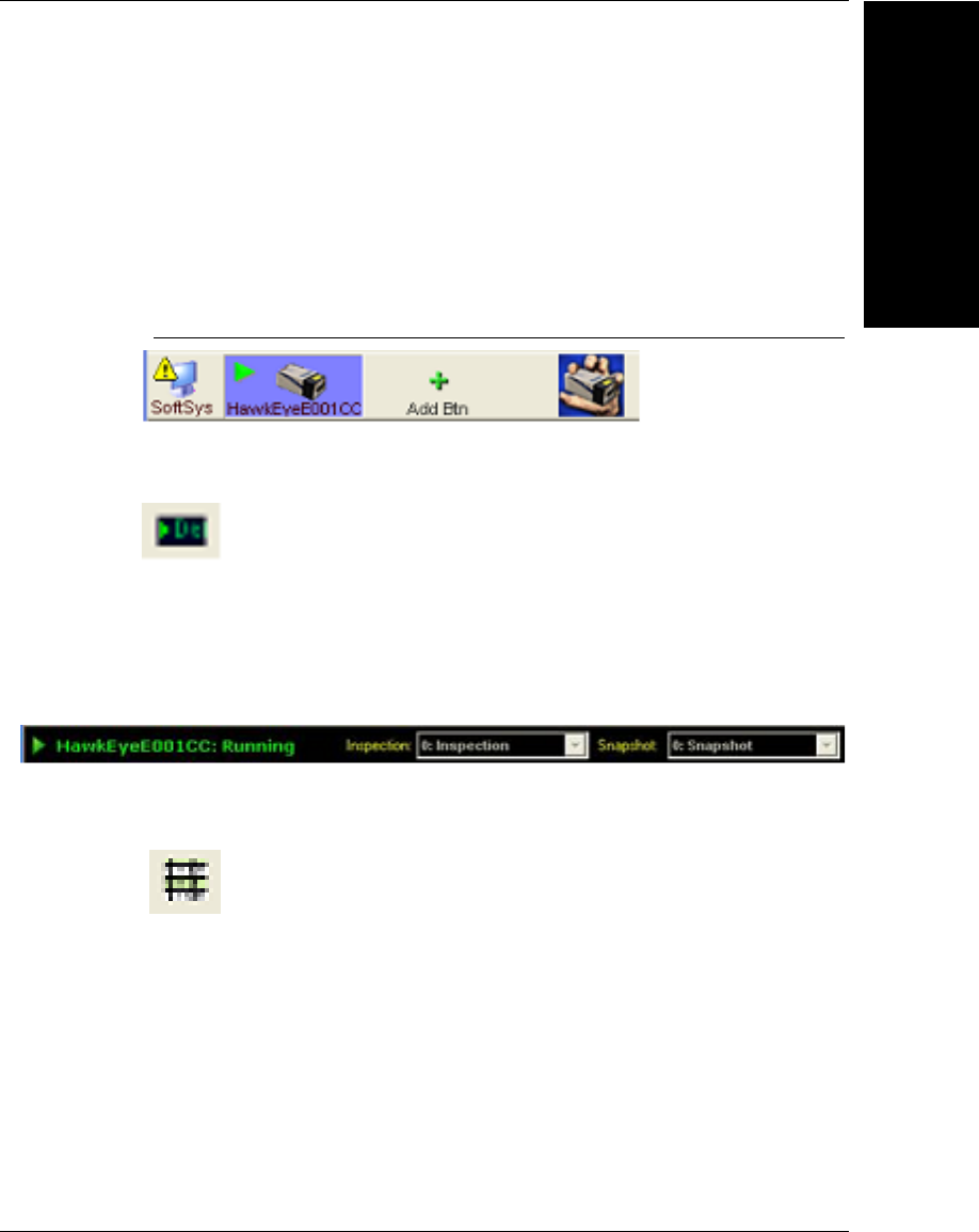
Visionscape Control Toolkit
Using VsKit
Components
5
Visionscape Programmer’s Kit (VSKit) Manual 5-23
VsDeviceButtons
You can use the VsDeviceButtons control as an alternative method to
selecting a device. It’s the same control used by FrontRunner to select a
device, along with the ability to add new device buttons (Add Btn) and
take control of a device. You can use it in your own application simply by
including it on a form.
FIGURE 5–12. VsDeviceButtons
VsDeviceBar
The VsDeviceBar control displays information about the currently
selected device and, when used along with the VsView control, allows
selection of the current Inspection and Snapshot. It’s the same control
used by FrontRunner. You can use it in your own application simply by
including it on a form.
VsReport
The VsReport control is the same control used by FrontRunner to display
an inspection report. You can use it in your own application simply by
including it on a form.
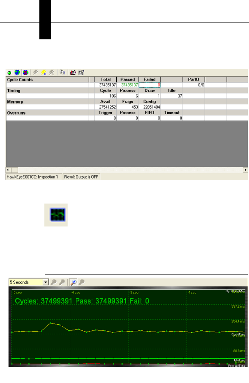
Chapter 5Using VsKit Components
5-24 Visionscape Programmer’s Kit (VSKit) Manual
FIGURE 5–13. VsReport Inspection Report
VsChart
The VsChart control is the same control used by FrontRunner to display
timing information for the current inspection. You can use it in your own
application simply by including it on a form.
FIGURE 5–14. VsChart Display
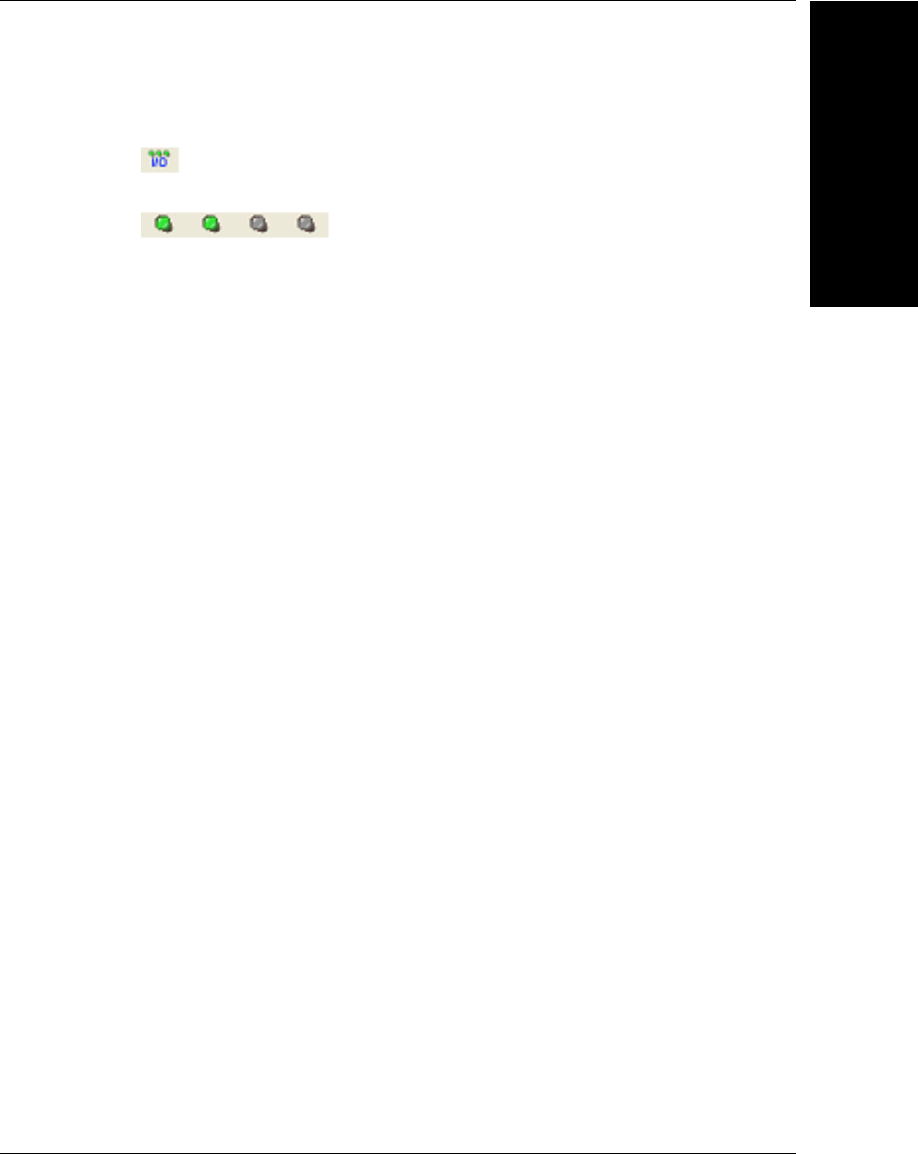
Visionscape Control Toolkit
Using VsKit
Components
5
Visionscape Programmer’s Kit (VSKit) Manual 5-25
VsIOButtons
The VsIOButtons control is a very convenient way of including access to
I/O in your application. Each LED displays the state of an IO point, and
pushing the LED button will toggle the state (of an input). To use this
control, simply place it on a form, and set the following properties (using
the Visual Basic Properties Window).
• IoType — The type of IO to monitor / control. The possible values are:
– IOTYPE_ANALOGOUT
– IOTYPE_PHYSICAL
– IOTYPE_RS422INPUT
– IOTYPE_RS422OUTPUT
– IOTYPE_SENSOR
– IOTYPE_SLAVESENSOR
– IOTYPE_STROBE
– IOTYPE_TTLINPUT
– IOTYPE_TTLOUTPUT
– IOTYPE_VIRTUAL
• IOPointFirst — The first IO Point of the selected type to be displayed
(representing the leftmost LED)
• IOPointLast — The last IO Point of the selected type to be displayed
(representing the rightmost LED)

Chapter 5Using VsKit Components
5-26 Visionscape Programmer’s Kit (VSKit) Manual
VsToolbar
The VsToolbar control is the same control that FrontRunner uses to
display a toolbar. You can use it in your own applications.
FIGURE 5–15. Toolbar

Visionscape Programmer’s Kit (VSKit) Manual 6-1
6
Using Report
Connections
6
CHAPTER 6 Using Report Connections
The AvpReportConnection Object
The AvpReportConnection object allows you to connect to an Inspection
on any Visionscape Device, and to receive uploaded results and/or
images across that connection. Results are returned to you via the
OnNewReport event, which passes you an AvpInspReport object. Then,
you can display the results and/or images contained in the report however
you wish, so this method provides you with the maximum amount of
control and flexibility. The AvpInspReport object will contain the inspection
stats (in the form of an AvpInspStats object) the uploaded results (in the
form of an AvpInspDataRecordCollection object) and potentially a
collection of images that you requested for upload (in a collection of
BufferDm objects). It does take more code to implement report
connections than it would to simply implement the VsRunView control, but
this approach gives you the maximum amount of control over the
performance of your application and also how your interface will look and
behave. Although VsRunView and the VsKit controls are much easier to
use, some advanced UIs with very specific goals regarding look, feel and
performance may be better off implementing report connections.
Creating a Report Connection
The AvpReportConnection object is contained within avpreport.dll. You’ll
need to add a reference to the following library:
+Visionscape Library: Reporting Objects

Chapter 6Using Report Connections
6-2 Visionscape Programmer’s Kit (VSKit) Manual
The following sample code demonstrates how to create a report
connection:
'declare a global variable using 'WithEvents'
Private WithEvents m_conn As AvpReportConnection
Private Sub Form_Load()
….
'create a connection to the first inspection on the
' device named "0740_01"
Set m_conn = New AvpReportConnection
m_conn.Connect "0740_01", 1
End Sub
'you will now receive the following event whenever a new
' report is available
Private Sub m_conn_OnNewReport(ByVal rptObj As _
AvpInspReport, ByVal bGoingToFreeze As Boolean)
'handle the elements of rptObj here
' rptObj.Stats holds inspections counts, times, etc
' rptObj.Results is a collection of uploaded results
End Sub
Pretty easy right? You simply declare a variable to be of type
AvpReportConnection using the WithEvents keyword. Then, you
instantiate the object, and call the Connect method, passing in the name
of the device, and the 1 based index of the inspection you want to receive
reports from. After establishing your connection, you will start to receive
the OnNewReport event at runtime whenever a new report is generated
(new reports are always generated at the end of an inspection cycle). The
event will pass you an inspection report in the form of the AvpInspReport
object. This object contains all of your inspection counts, timing, uploaded
results, and it can even contain images if you choose to add them to the
report (more on that later). We will cover the contents of the
AvpInspReport object in more detail later on in this chapter.
Connection Details
As we just demonstrated, the Connect method of AvpReportConnection
establishes a report connection to one of the inspections on a running
device:

The AvpReportConnection Object
Using Report
Connections
6
Visionscape Programmer’s Kit (VSKit) Manual 6-3
Sub Connect(sysNameorObj, inspNameOrIndex,_
[categoryFlags As Long = 3])
• sysNameorObj — This is generally a string that specifies the name of
the Device you are trying to connect to. You can also pass an object
of type AvpSystem, but this is not common.
• inspNameOrIndex — Either the 1 based index of the inspection you
want to receive reports from, or a string containing its symbolic name.
• categoryFlags — Optional. The bits of this integer value specify what
type of data should be automatically included or excluded from the
report:
– Bit 1 — Include inspection stats (counts, timing etc).
– Bit 2 — Include the results selected for upload.
– Bit 3 — Always exclude images from the report. This is the
default, which means bits 1 and 2 are on, so the default includes
the inspection stats and the results selected for upload.
– Bit 4 — Ignore the Inspection Step's “Results Upload Qualified
Condition” expression and always include the results selected for
upload.
So, once you’ve connected, by default, you will receive the inspection
stats and the results selected for upload, but you will not receive any
images unless you explicitly add them to the report via the
DataRecordAdd method (more on this later), or add them to the list of
uploaded results in your inspection (using FrontRunner).
There are several other important properties of the AvpReportConnection
object that allow you to tweak the performance of your report connection.
• Property DropWhenBusy As Boolean
Note: The default for this property is True (reports will be
dropped if the connection is too busy to send them). This means
your connection will be lossy. If you require a lossless
connection (you don’t want any reports to be dropped), then you
must set this property to False. A lossless connection may
impact the performance of your inspection. If your inspection
completes a cycle, and it tries to send a report, but your report

Chapter 6Using Report Connections
6-4 Visionscape Programmer’s Kit (VSKit) Manual
connection is still busy trying to send the report from the
previous cycle, then the inspection will block until it can send
the new report. This could cause problems for high-speed, time-
critical inspections. If this property is set to True, the Inspection
would not block; it would simply drop the report and continue on
to the next cycle.
• Property MaxRate As Long
Use this property to set the maximum number of reports that can be
sent per second. The default is 0, which means to send the maximum
number of reports possible, no limit. A setting of 2 would mean no
more than 2 per second. Using 2 as an example, the connection
would translate this setting into a number of milliseconds (1000ms / 2
= 500ms). Whenever the connection sends a report, it will start
timing, and if another report is ready for transfer in less than 500ms,
then it will be thrown away. In other words, you would only be allowed
to send one report every 500ms.
• Property FreezeMode As tagRPT_FREEZE_MODE
By default, your report connection will send a report after every
inspection cycle. You can use this property to change that behavior
by specifying one of the following values:
– RFRZ_SHOW_ALL — Default, send all reports.
– RFRZ_SHOW_FAILED — Send only reports for failed
inspections
– RFRZ_FREEZE_THIS — Freezes the report connection, which
means no more reports will be sent.
– RFRZ_FREEZE_NEXT_FAILED — Freezes the report
connection on the next failed inspection. Not to be confused with
the SHOW_FAILED option, reports will be sent continuously
while in this mode until there is an inspection failure, at which
time it will freeze.
– RFRZ_FREEZE_LAST_FAILED — Switching to this mode will
cause a report to be sent from the last failed inspection cycle, and
then the connection will be frozen.

The AvpReportConnection Object
Using Report
Connections
6
Visionscape Programmer’s Kit (VSKit) Manual 6-5
– RFRZ_FREEZE_NEXT_QUAL — This option only applies if you
are using the “Freeze Qualified Condition” datum in the
Inspection Step. This datum allows you to specify an inspection
condition which, if evaluated as True, will freeze the connection.
Without this setting, the datum in the inspection step has no effect
on your report connection.
Note: The tag RPT_FREEZE_MODE enum is actually defined in
a different dll. It’s defined in vsreport.dll. Add the following
reference to your project to access it:
+Visionscape Library: VsReport
• Property ExcludeImages As Boolean
The default is False. When set to True, any images buffers that have
been added to the list of results to upload will be excluded from the
report. This property has the same effect as bit 3 in the categoryFlags
parameter of the Connect method.
• Property IgnoreUploadQualifier As Boolean
The default is False. When set to True, ignore the Inspection Step’s
“Results Upload Qualified Condition” datum and always send the
report. This property has the same effect as bit 4 of the categoryFlags
parameter of the Connect method.
• Property GraphicsOn As Boolean
The default is True. When set to False, any images included in the
report will not include graphics.
Adding Records to Your Report Programmatically
When you establish a report connection, you will typically receive just the
results that you selected for upload when you were building your Job in
FrontRunner. You have the option of adding other datums to the report
however, and you do this by calling the DataRecordAdd method:
• Sub DataRecordAdd(dataRecName As String)
dataRecName — A string that specifies the symbolic name of the
datum that you want to add to the report. This must be the full path to
the datum, up to its parent Snapshot Step.
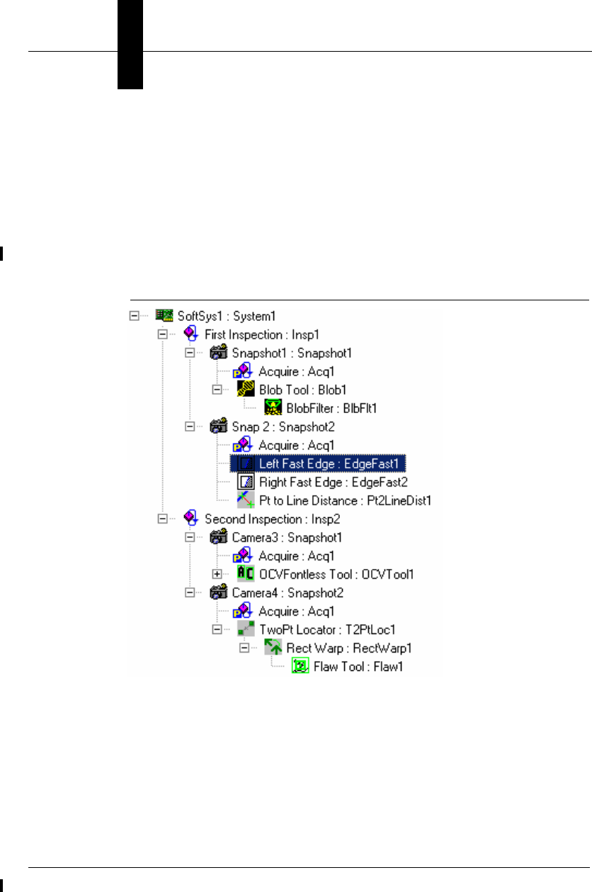
Chapter 6Using Report Connections
6-6 Visionscape Programmer’s Kit (VSKit) Manual
This method can add ANY datum to the report. That means integer
values, floating point values, distances, points, lines, and even image
buffers. You must establish your connection first (using the Connect
method) before trying to call DataRecordAdd. You pass in the
symbolic name of the datum you want to add (this must be the full
path to the datum, up to its parent Snapshot Step). Consider the Job
tree shown below; this is from the ProgSample_MultiCam.avp file
installed with the Visionscape VSKit Programmers Toolkit:
FIGURE 6–1. Job Tree
The Job Tree shown here is displaying the symbolic names for each Step.
The first Fast Edge Step under the second Snapshot Step is highlighted.
Let’s say we wanted to add the output edge point from this Fast Edge
Step to our list of uploaded results. The symbolic name for the “Edge
Point” datum is EdgePt (remember, you can look up the symbolic name of
any datum using the StepBrowser utility, refer to “Using StepBrowser to
Look Up Symbolic Names” on page 2-30 for details). The symbolic name
of the step is EdgeFast1, and its parent Snapshot Step’s symbolic name
is Snapshot2. So, we would make the following call to DataRecordAdd:

The AvpReportConnection Object
Using Report
Connections
6
Visionscape Programmer’s Kit (VSKit) Manual 6-7
m_conn.DataRecordAdd "Snapshot2.EdgeFast1.EdgePt"
The string specifies the complete path through the tree from the parent
Snapshot Step to the datum you are adding. As another example, let’s
say our report connection was connected to the second inspection in our
example Job above (user name = “Second Inspection”). Now, let’s say we
wanted to add the “Output Value” datum (symbolic name “Val”) of the
Flaw tool that lives under the second snapshot. Again, we need to specify
the full path to the datum, so the call would look like this:
m_conn.DataRecordAdd _
"Snapshot2.T2PtLoc1.RectWarp1.Flaw1.Val"
This is a more complex path, and hopefully it illustrates how the full path
of your datum must be specified. The Flaw tool’s parent is the Rect Warp
step, its parent is the Two Pt Locator step, and its parent is the Snapshot,
so the symbolic names of each must be included in the path. The
AvpReportConnection object uses this string to walk the tree and find
your datum so, if the path is incorrect, the DataRecordAdd call will fail. If
you have your Job loaded in memory, you can use the various techniques
described in Chapter 2 to walk through the tree and build a string like this
programmatically, if needed. If you do not have the Job loaded locally,
such as when you are simply monitoring a smart camera, you can query
the namespace of the device, using the VsDevice object. Then, you could
build your string programmatically using the tree of VsNameNode objects
contained in the Namespace property of VsDevice (refer to “Namespace
Information” on page 3-21 for details).
Adding Images to your Report
As we mentioned previously, there are two ways to include images in your
inspection report.
• When programming your Job in FrontRunner, go to the Inspection
Step(s) and add the output buffer of the snapshot(s) you want to
upload to the “Select Results to Upload” list. Then, these buffers will
be added to the Images collection of the AvpInspReport object you
receive in the OnNewReport event.
• Add them programmatically using the DataRecordAdd method.
The first option should be self explanatory, so let’s focus on the second
option. In the previous section, we explained how to add datums to your

Chapter 6Using Report Connections
6-8 Visionscape Programmer’s Kit (VSKit) Manual
inspection report using the DataRecordAdd method. You should
understand that the images in your Job are contained within Buffer Datum
objects and are, therefore, added to the inspection report just like any
other datum. Each Snapshot Step has an output Datum named
“SnapOutputBuffer”, symbolic name “BufOut”. This datum always holds
the most recent image acquired by the Snapshot. So, the call to include
the image from a Snapshot would look something like this:
m_conn.DataRecordAdd "Snapshot1.BufOut"
Our assumption here is that the symbolic name of the Snapshot is
“Snapshot1”. But, what if you don’t know what the symbolic name of the
Snapshot is? What if you have multiple Snapshots and want to add all of
their images to your report? Then you’ll want to write a little code to
examine the Job and dynamically figure out how many snapshots are
present, get the symbolic name of each, and build the correct string to
pass to DataRecordAdd.
Adding All Snapshot Images by Analyzing the Job
If you are using a JobStep to load the AVP file into memory, it’s very easy
to scan the Job and automatically add all the Snapshot images to your
report. You would simply find the Inspection step that you are establishing
your report connection to, and then find all of the Snapshot Steps under it.
Once you've found all the Snapshot Steps, you simply loop through them,
build a string for each using its symbolic name with the string “.BufOut”
appended, and pass this string to DataRecordAdd. The following example
demonstrates how you might load the example job
“ProgSample_MultiCam.avp”, download it to the first device in your
system, create a report connection to the first inspection in the Job, and
then add the images from every snapshot under that inspection to the
report:
Private m_Job As JobStep
Private m_Coord As VsCoordinator
Private m_Dev As VsDevice
Private WithEvents m_conn As AvpReportConnection
Private Sub Form_Load()
Set m_Coord = New VsCoordinator
'get the first available device
Set m_Dev = m_Coord(1)
'create a job step and load our sample job

The AvpReportConnection Object
Using Report
Connections
6
Visionscape Programmer’s Kit (VSKit) Manual 6-9
Set m_Job = New JobStep
m_Job.Load "C:\Vscape\Tutorials &
Samples\Sample Jobs\ProgSample_MultiCam.avp"
'get the first vision system step in the job
Dim vs As VisionSystemStep
Set vs = m_Job(1)
'prepare the device to run this job
m_Dev.Download vs, 0
'create our report connection
Set m_conn = New AvpReportConnection
'connect to the first inspection on our device
m_conn.Connect m_Dev.Name, 1
'if connection was successful....
If m_conn.Connected Then
'find all the snapshots under the first inspection
Dim insp As Step
Dim allsnaps As AvpCollection, snap As Step
'find the first inspection step under
' the VisionSystem Step
Set insp = vs.Find("Step.Inspection", FIND_BY_TYPE)
'find all the snapshots under this inspection
Set allsnaps = insp.FindByType("Step.Snapshot")
For Each snap In allsnaps
'add this snapshot's image to our report
m_conn.DataRecordAdd snap.NameSym & ".BufOut"
Next
End If
'now start the inspections
m_Dev.StartInspection
End Sub
Adding All Snapshot Images by Analyzing the Namespace
The previous example works well when your application is loading the
AVP file. But the typical smart camera application will simply connect to
the device when it’s already running, and will then simply begin
monitoring the images and results without ever needing to load an AVP
file. You may also decide to use the VsDevice DownloadAVP method,
rather than using a JobStep to load the Job yourself. In these cases, you
will not have the AVP loaded locally and will, therefore, need to analyze

Chapter 6Using Report Connections
6-10 Visionscape Programmer’s Kit (VSKit) Manual
the Namespace on the Device in order to discover how many Inspections
and Snapshots are present. The following is example code that
demonstrates how to do this. Just as in our last example, we will once
again find the first Inspection in the Job, and then find all of the Snapshots
underneath it. The only difference is that we're working with
VsNameNodes instead of the actual Steps (refer to “Namespace
Information” on page 3-21 for more information on Namespaces and the
VsNameNode object):
'create our report connection
Set m_conn = New AvpReportConnection
'connect to the first inspection
m_conn.Connect m_Dev.Name, 1
'if connection was successful....
If m_conn.Connected Then
Dim colInsp As VsNameNodeCollection
Dim nnInsp As VsNameNode
Dim colSnap As VsNameNodeCollection
Dim nnSnap As VsNameNode
'tell device to update its namespace information
m_Dev.QueryNamespace
'Get the list of inspections
Set colInsp = m_Dev.ListInspections
'if any inspections were found…
If colInsp.Count > 0 Then
'get the first inspection name node
Set nnInsp = colInsp(1)
'get all the snapshots under this inspection
Set colSnap = nnInsp.SearchForType(
"Step.Snapshot.1")
For Each nnSnap In colSnap
m_conn.DataRecordAdd nnSnap.SymbolicName & _
".BufOut"
Next
End If
End If
Now That I Have Images, How Do I Display Them?
See “Handling Images” starting on page 6-14.

Handling Inspection Reports: The AvpInspReport Object
Using Report
Connections
6
Visionscape Programmer’s Kit (VSKit) Manual 6-11
Handling Inspection Reports: The AvpInspReport Object
At the end of each inspection cycle, the Inspection Step will create an
AvpInspReport object that contains the cycle data you requested from
your AvpReportConnection object. This report is then passed to you via
the AvpReportConnection's OnNewReport event. So think of the
AvpInspReport object as a report on one inspection cycle. In this section
we will provide some sample code that demonstrates how to handle
inspection data, stats, and images. For comprehensive descriptions of all
of the objects mentioned in this section, please refer to “Inspection Report
Details” starting on page 6-17.
Handling Inspection Results
Here we will demonstrate how to access the uploaded result data from
your inspection report. What data is included in the inspection report?
That is entirely up to you, you select what values you want to be included.
You select your results in one of three ways:
• If you created your Job in FrontRunner, any data that you selected in
the Inspection Step's “Select Results To Upload” datum will be
included in your report. (See Note below.)
• If you created your Job programmatically, any data that you selected
in the Inspection Step's “ResToUpld” datum, or any datums for which
you set the TagForUpload property to True will be included in your
report. (See Note below.)
• You can add any value to the report programmatically using the
AvpReportConnection's DataRecordAdd method.
Note: This assumes that when you call the Connect method of your
AvpReportConnection object, you do not specify a value for the
CategoryFlags parameter. If you do pass a value for CategoryFlags, then
you must make sure that Bit 2 is on in the value. Refer to the “Connect
Details” section for more information.
Inspection results will be collected within the Results property of the
AvpInspReport object. The Results property is a collection of
AvpInspDataRecord objects. The AvpInspDataRecord object represents
a single inspection result, and it can hold both scalar and array data.
Refer to the next section for a complete description of the

Chapter 6Using Report Connections
6-12 Visionscape Programmer’s Kit (VSKit) Manual
AvpInspDataRecord object. So let's look at an example of how you might
handle the inspection results in the OnNewReport event. We will cycle
through each of the results and format the value of each into a string:
Private Sub mConn_OnNewReport(ByVal rptObj As AVPREPORTLib.IAvpInspReport, ByVal bGoingToFreeze
As Boolean)
Dim record As AvpInspDataRecord, strResult As String
' the 'results' collection holds our inspection data,
'cycle through each result like this...
For Each record In rptObj.results
'check the error code of the result,
' to insure it ran successfully
If record.Error = 0 Then '0 means no errors
'The 'value' property returns a variant that
' holds the data for the result.
' The example FormatResult function will
' format the variant data into a string,
' separating array values with a ",", and
' showing 3 decimal places for floating point
' values.
strResult = FormatResult(record.value, ",", 3)
Else
strResult = "Error: " & record.Error
End If
'dump the name and the value of each result
Debug.Print record.Name & " = " & strResult
'Do you want to perform special processing on
' certain Datum types?
' You could check for specific types like this...
Select Case record.Type
Case "Datum.Point.1"
Debug.Print "I found a Point Datum!!"
Case "Datum.Int.1"
Debug.Print "I found an integer datum!!"
Case "Datum.Line.1"
Debug.Print "I found a Line Datum!!"
Case "Datum.Double.1"
Debug.Print "I found a Double precision floating point datum!!"
Case "Datum.Distance.1"
Debug.Print "I found a Distance Datum!!"
Case Else
Debug.Print "I wasn't expecting this type: " & record.Type
End Select
Next
'you can access a specific record like this:
Set record = rptObj.results(3) 'get the 3rd result
strResult = FormatResult(record.value, ",", 3)
Debug.Print "Value of Result 3 = " & strResult
End Sub
'''''''''''''''''''''''''
' FormatResult:
'An example of formatting Variant data into a string
Private Function FormatResult(vRes As Variant, strSeparator
As String, intPrecision As Integer) As String
Dim strPrec As String, i As Integer, j As Integer
Dim strOutput As String, strTemp As String

Handling Inspection Reports: The AvpInspReport Object
Using Report
Connections
6
Visionscape Programmer’s Kit (VSKit) Manual 6-13
Dim SecBound As Integer
On Error Resume Next
If IsEmpty(vRes) Then
strOutput = ""
ElseIf IsArray(vRes) Then
'This variant holds array data,
' is it 1 dimensional or 2 dimensional?
SecBound = -1
SecBound = UBound(vRes, 2) 'SecBound stays -1 if 1D
For i = 0 To UBound(vRes)
'IF 2 DIMENSIONAL
If SecBound > -1 Then '
For j = 0 To SecBound
strTemp = FormatResult(vRes(i, j),
strSeparator, intPrecision)
If strOutput = "" Then
strOutput = strTemp
Else
strOutput = strOutput &
strSeparator & strTemp
End If
Next j
Else 'IF ONE DIMENSIONAL
strTemp = FormatResult(vRes(i),
strSeparator, intPrecision)
If strOutput = "" Then
strOutput = strTemp
Else
strOutput = strOutput &
strSeparator & strTemp
End If
End If
Next i
Else 'NOT AN ARRAY
Select Case VarType(vRes)
'if floating point, only show
' the specified number of decimal places
Case vbDouble, vbSingle
strPrec = String(intPrecision, "0")
strPrec = "0." & strPrec
strOutput = Format(vRes, strPrec)
Case Else
strOutput = vRes
End Select
End If
FormatResult = strOutput
End Function
Handling Inspection Statistics
When we use the term “Inspection Statistics”, we mean data like the
Inspection counts (total inspected, passed, rejected), timing information
like process time and cycle time, as well as overrun information. The
Inspection Statistics are contained within the Stats property of the

Chapter 6Using Report Connections
6-14 Visionscape Programmer’s Kit (VSKit) Manual
AvpInspReport object. The Stats property returns a reference to an
AvpInspStats object. Refer to the next section for a complete description
of this object. Following is an example of how to access this data in the
OnNewReport event:
Private Sub mConn_OnNewReport(ByVal rptObj As AVPREPORTLib.IAvpInspReport, ByVal
bGoingToFreeze As Boolean)
'Inspection Stats are in the Stats object
Dim InspStats As AvpInspStats
Set InspStats = rptObj.stats
'you can check the overall pass/fail
' status of the inspection like this
If InspStats.Passed Then
Debug.Print "Inspection Passed"
Else
Debug.Print "Inspection Failed"
End If
'The inspection counts...
Debug.Print InspStats.CycleCount 'total inspected
Debug.Print InspStats.PassedCount 'total passed
Debug.Print InspStats.FailedCount 'total failed
'common timing information...
Debug.Print InspStats.ProcessTime
Debug.Print InspStats.DrawTime
Debug.Print InspStats.CycleTime
Debug.Print InspStats.RatePPM
'check if you've had any overruns
If InspStats.ProcessOverruns > 0 Or _
InspStats.TriggerOverruns > 0 Or _
InspStats.FifoOverruns > 0 Then
Debug.Print "Woops, We've had an Overrun"
End If
End Sub
Handling Images
If you are uploading Images in your report connection, you probably want
to do one of two things with them:
• Display them
• Save them to disk

Handling Inspection Reports: The AvpInspReport Object
Using Report
Connections
6
Visionscape Programmer’s Kit (VSKit) Manual 6-15
Fortunately, it is very easy to do both of these things.
Displaying Images
The easiest and most powerful Visionscape control for displaying images
is the Buffer Manager control. Add the following Component to your
project in order to access Buffer Manager:
+Visionscape Controls: Buffer Manager
When you receive the OnNewReport event, the Images collection of your
AvpInspReport object will contain the images from every snapshot you
added to the report. The Images property is a collection of BufferDm
objects. Visionscape always uses the BufferDm object to represent an
image buffer. The Buffer Manager control displays BufferDms, you simply
need to call its Edit method, and pass it the handle of the BufferDm you
wish to display. So to display the first image in your report, drop a Buffer
Manager control on to your form, change its name to ctlBufMgr, and do
the following in OnNewReport:
Private Sub m_conn_OnNewReport(ByVal rptObj As
AVPREPORTLib.IAvpInspReport,
ByVal bGoingToFreeze As Boolean)
Dim buf As BufferDm
'make sure we have images
If rptObj.Images.Count > 0 Then
'get the 1st buffer datum from the Images collection
Set buf = rptObj.Images(1)
'display the buffer in our buffer manager control
ctlBufMgr.Edit buf.Handle, 0 'last param always 0
End If
End Sub
You could also use the VsFilmStrip control to display your images. This is
documented in chapter 5. To display an image in a VsFilmStrip named
ctlFStrip, simply replace the call to ctlBufMgr1.Edit in our example above
with the following line:
ctlFStrip.NewBufferDm rptObj.Images(1), rptObj.stats.Passed
Saving Images to Disk
Saving images to disk is very easy. The BufferDm object has a built in
SaveImage method to handle this for you. When you call SaveImage, you
specify the path and file name where you want the image to be saved,
and you specify what type of image file you want. Your options are TIFF

Chapter 6Using Report Connections
6-16 Visionscape Programmer’s Kit (VSKit) Manual
and BMP. The following example shows how you might save failed
images to disk in the TIFF format.
Private Sub mConn_OnNewReport(ByVal rptObj As AVPREPORTLib.IAvpInspReport, ByVal
bGoingToFreeze As Boolean)
Dim buf As BufferDm
Static FailCount As Long
'make sure we have images
If rptObj.Images.Count > 0 Then
'get the 1st BufferDM from the Images collection
Set buf = rptObj.Images(1)
'save only failed images
If rptObj.stats.Passed Then
FailCount = FailCount + 1
buf.SaveImage App.Path & "\FailedImage" & _
FailCount & ".tif", ftTIF
End If
End If
End Sub
In this example, we saved images as TIFFs. If your goal is to be able to
reload the failed images into FrontRunner and run your inspection on
them in order to determine why your inspection is failing ( a common
debugging technique ), then you should always save them as TIFFs
without graphics. If your goal is to be able to simply display the failed
images at a later date, then you may want the images to be saved with
their overlay graphics. If that is the case, then your call to SaveImage
would look like this:
buf.SaveImage "C:\Imgs\MyImage.bmp", ftBMP + ftWithGraphics
Performance Concerns?
A common concern expressed about using report connections to display
images is performance. Some users assume that this approach will be
slow, much slower than using one of our standard controls like
VsRunView. In fact, this is exactly how the VsRunView control displays
images. It establishes a report connection, adds all the snapshot images
to it, and then displays each image in a Buffer Manager control when it
receives the OnNewReport event. The Runtime Manager also displays
images using a report connection and a Buffer Manager. So when you
use this technique, you are mimicking the standard Visionscape controls.

Inspection Report Details
Using Report
Connections
6
Visionscape Programmer’s Kit (VSKit) Manual 6-17
Inspection Report Details
This section provides details on the AvpInspReport object, and the
various other data objects that are contained within it (AvpInspStats,
AvpInspDataRecord, etc.).
The AvpInspReport Object
As mentioned in the previous section, the Inspection Step will create an
AvpInspReport object at the end of each inspection cycle, and populate it
with the data you requested from your AvpReportConnection object. So
think of the AvpInspReport object as a report on one inspection cycle.
You will receive this report via the AvpReportConnection's OnNewReport
event. The report data is accessed via the following properties:
• Property Stats As AvpInspStats
Contains the inspection status (pass/fail), cycle counts, timing, etc.
Refer to “AvpInspStats Object” on page 6-19 for a complete
description.
• Property StatsMem As AvpMemStats
Contains information on the device's current memory usage. Refer to
“AvpMemStats” on page 6-24 for a complete description.
• Property Results As AvpInspDataRecordCollection
Holds the uploaded results from the inspection. This is a collection of
AvpInpsDataRecord objects. There will be one record in the collection
for every result selected for upload. Refer to “AvpInspDataRecord
Object” on page 6-22 for a complete description.
• Property Images As IAvpCollection
A collection of BufferDm objects. This collection holds all buffers that
were added to the report, if any. The default report connection does
not contain images, so this collection will be empty unless you have
added images to the report. Refer to the previous section for a
description of how to do this.
The AvpInspReport also provides the following useful properties and
methods:

Chapter 6Using Report Connections
6-18 Visionscape Programmer’s Kit (VSKit) Manual
• Property Name As String
Returns the User Name of the Inspection Step that generated the
report.
• Property NameSym As String
Returns the symbolic name of the Inspection step that generated the
report.
• Property InspIndex As Long
Returns the 0 based index of the inspection that generated the report.
• Property Timestamp As Double
Returns timestamp from when report was created.
• Function ReportString(LogOptions As AvpLogOptions) As String
LogOptions: An AvpLogOptions object configured with your desired
formatting options.
This function converts your report data into a string based on the
options you specify in the LogOptions parameter. Refer to “Logging
Results to File” on page 4-14 for a complete description of the
AvpLogOptions object.

Inspection Report Details
Using Report
Connections
6
Visionscape Programmer’s Kit (VSKit) Manual 6-19
• Sub FileSave(bszName As String)
Sub FileLoad(bszName As String)
bszName: File path to which report should be saved/loaded.
These two methods allow you to save and reload inspection reports
to disk. The entire contents of the report, including images, will be
saved.
• Sub CopyImagesToStandardMemory()
Copies images out of DMA memory into standard memory for long
term memory storage. If you are queuing up the images you receive
from your reports and want to hold onto them for a while, you should
understand that the images are stored in DMA memory, and the
Visionscape framework may free those buffers at any time.
Therefore, you should call this method to copy the image buffers out
of DMA memory to standard PC memory, and then you can hold onto
them for as long as you need.
AvpInspStats Object
The properties of this object provide information on the cycle counts,
inspection timing, overruns, buffer usage, etc. A description of each
property follows:
• Property ASICTime As Long
The time spent in ASIC processing.
• Property BufferPoolCount([snapIndex As Long = 1]) As Long
The number of buffers in the bufferpool for a specific snap (One-
based index).
• Property CameraTimeouts As Long
The count of camera timeouts for all snaps.
• Property CycleCount As Long
This property returns inspection cycle count.
• Property CycleTime As Long
This property returns Cycle time in msecs.

Chapter 6Using Report Connections
6-20 Visionscape Programmer’s Kit (VSKit) Manual
• Property CycleTimeMax As Long
This property returns the maximum cycle time in msecs.
• Property DMATime As Long
The time spent in DMA transfers.
• Property DrawTime As Long
This property returns the time in msecs spent creating graphics
metafile.
• Property FailedCount As Long
This property returns the number of failed inspections.
• Property FifoOverruns As Long
The count of fifo overruns for all snaps.
• Property IdleTime As Long
This property returns the idle time in msecs.
• Property PartQSizeCur As Long
Read-only. The current number of entries in the Part Q.
• Property PartQSizeMax As Long
Read-only. The maximum Size of the Part Q.
• Property Passed As Boolean
True if inspection passed, False if inspection failed.
• Property PassedCount As Long
This property returns the number of passed inspections.
• Property ProcessOverruns As Long
The count of processing overruns for all snaps.

Inspection Report Details
Using Report
Connections
6
Visionscape Programmer’s Kit (VSKit) Manual 6-21
• Property ProcessTime As Long
This property returns the processing time in msecs (time spent in
inspection processing images).
• Property ProcessTimeMax As Long
This property returns the maximum processing time.
• Property RatePPM As Long
This property returns the Inspection rate as parts per minute.
• Property RatePPMMax As Long
This property returns the maximum Inspection rate as parts per
minute.
• Property SnapBufferpoolUsed(snapIndex As Long) As Long
The number of bufferpool buffers used at snap time.
• Property SnapCameraTimeouts(snapIndex As Long) As Long
The number of camera timeouts for specific snap.
• Property SnapCount As Long
Read-only. The number of individual snapshot statistics.
• Property SnapFifoOverruns(snapIndex As Long) As Long
The number of FIFO overruns for a specific snap.
• Property SnapProcessOverruns(snapIndex As Long) As Long
The number of processing overruns for a specific snap.
• Property SnapTriggerOverruns(snapIndex As Long) As Long
The number of trigger overruns for this specific snap.

Chapter 6Using Report Connections
6-22 Visionscape Programmer’s Kit (VSKit) Manual
• Property TriggerOverruns As Long
The count of trigger overruns for all snaps.
AvpInspDataRecord Object
This object wraps a single result in the list of uploaded results. The
properties of this object allow you to access the result data, its name, its
error code, etc.
• Property Value As Variant
This property returns the value of the datum that was selected for
upload. This value may be scalar, or it may be an array, it depends on
the datum type. The Type property can be used to check the datum
type of this result. If empty, then the Error property will be set.
• Property ValueCalibrated As Variant
If the Inspection is calibrated, this property returns the result data in
calibrated units. If not calibrated, this is identical to the Value
property.
• Property ValueNonCalibrated As Variant
This property returns the non-calibrated value of the datum. If empty,
then the Error property will be set. If your inspection is calibrated, you
can use this property to access the data in pixel units, for those
occasions when you don't want calibrated units.
• Function ValueAsString([strArrayDim1Separator As String = ","],
[strArrayDim2Separator As String = "\r\n"]) As String
This property returns the Value as a text string for the datums that
support this option. Optionally, when dealing with types that return
array values, you can specify the character that separates the 1st and
2nd dimensions of the array data.
• Property Error As Long
This property returns the error code of the datum. This will be 0 when
the Step ran successfully, non-zero indicates an error. In many cases,
an error will mean that the data was not updated, so you should not

Inspection Report Details
Using Report
Connections
6
Visionscape Programmer’s Kit (VSKit) Manual 6-23
trust the data returned by one of the Value properties if Error is non-
zero.

Chapter 6Using Report Connections
6-24 Visionscape Programmer’s Kit (VSKit) Manual
• Property Name As String
This property returns the user name of the datum that generated this
record. Will be in the form Step.Datum.
• Property NameSym As String
This property returns the symbolic name of the datum that generated
this record. It will be in the form Step1.Dm.
• Property Type As String
This property returns the datum type of the datum that generated this
record. Will be returned in the form Datum.XXX.
• Property HaveCalibratedData As Boolean
Read-only. This property returns True if data is calibrated.
AvpMemStats
This object provides information on the state of a Device's memory. You
should understand that the data in this object is only valid when dealing
with a smart camera. The data is not valid when dealing with host based
devices, as your inspections are running under Windows in that case, and
this object is not needed (there are many Windows API calls available
that will provide you with information on the current state of PC memory).
The properties of this object provide the following information:
• Property GenAvail As Long
Read-only. This property returns the size in bytes of available
memory in the general memory heap.
• Property GenContig As Long
Read-only. This property returns the size in bytes of the largest
contiguous block of memory in the general heap.
• Property GenFrags As Long
Read-only. This property returns the number of memory fragments in
the general memory heap.
• Property GenSize As Long

Inspection Report Details
Using Report
Connections
6
Visionscape Programmer’s Kit (VSKit) Manual 6-25
This property returns the overall size in bytes of the general memory
heap.
• Property GenUsed As Long
This property returns the size in bytes of the amount of used general
memory.
• Property GenUsedMax As Long
This property returns the maximum general memory used ever (in
bytes).
Part Queue Connections
Note: If you are unfamiliar with the Part Queue, see the Visionscape
FrontRunner User Manual for more information.
The AvpPartQueueConnection object retrieves Part Queue data from a
running inspection. When programming your inspection in FrontRunner,
you must enable the Part Queue, set its size, and set the type of data you
want to queue up. Once running, the inspection will then queue up
images and results based on your settings. A typical scenario would be
that the user would wish to queue up the last 20 failed images. If you wish
to retrieve this Part Queue data in your application, then you would use
the AvpPartQueueConnection object, which is used in a manner that is
very similar to the AvpReportConnection object. Generally, you would
follow these steps:
1. Instantiate an AvpPartQueueConnection object, and connect it to the
Inspection using the Connect method.
2. Use the Summary method to determine if there are any records in the
Part Queue.
3. If any, retrieve them all using the RecordGetAll method, which returns
you an AvpInspReportCollection object, which is a collection of
AvpInspReport objects, which we have already covered at length.
Here is an example function demonstrating how you might retrieve the
Part Queue from a specified inspection on a specified device.

Chapter 6Using Report Connections
6-26 Visionscape Programmer’s Kit (VSKit) Manual
Private Sub GetQueue(dev as VsDevice, InspIndex as Integer)
Dim connQueue As New AvpPartQueueConnection
Dim queueRecords As AvpInspReportCollection
Dim record As AvpInspReport
Dim ison As Boolean, maxSize As Long
Dim curSize As Long, stats() As Object
'CONNECT TO THE QUEUE
connQueue.Connect dev.Name, InspIndex
'GET THE QUEUE SUMMARY
connQueue.Summary ison, maxSize, curSize, stats
'IF THE QUEUE IS NOT EMPTY, RETRIEVE IT
If curSize > 0 Then
'RETRIEVE THE PART QUEUE
Set queueRecords = connQueue.RecordGetAll
For Each record In queueRecords
'record is AvpInspReport object
' the images are in record.Images
' results are in record.Results
' stats are in record.Stats
Next
Else
MsgBox "Queue is Currently Empty"
End If
'DISCONNECT
connQueue.Disconnect
End Sub
By passing the AvpInspReportCollection object to a separate form, you
could easily create your own Q View screen by adding in a Buffer
Manager to show the images and any controls you wish to display the
results.
AvpPartQueueConnection
Let’s take a closer look at the methods and properties of this object,
starting with the Connect method:
• Sub Connect(sysNameorObj, inspNameOrIndex)

Inspection Report Details
Using Report
Connections
6
Visionscape Programmer’s Kit (VSKit) Manual 6-27
sysNameorObj — Typically, this is a string holding the name of the
Device you are connecting to. Can also be a reference to an
AvpSystem object.
inspNameOrIndex — Specifies either the 1 based index of the
inspection you want to connect to, or its symbolic name.
Connects to the specific Inspection on the given device. Raises an
exception if the connection should fail.
• Sub Disconnect()
Disconnects from the device.
• Sub Summary(isOn As Boolean, maxEntries As Long, curEntries As
Long, overallStats() As Object)
– isOn — Sets this variable to True if the Part Queue is turned on
for this inspection, False if it’s off.
– maxEntries — Returns the maximum size of the Part Queue. So,
if the user configured the Part Queue to hold 20 records, this
variable would be set to 20.
– curEntries — Returns the current number of entries in the Part
Queue. If 0, you know Part Queue is empty.
– overallStats() — This array of type Object will be filled with
AvpInspStats objects, one for each record in the Part Queue.
This gives you a quick way to scan for failed entries, or to check
the cycle count to see how many cycles elapsed between records
being added to the Part Queue.
Retrieves a summary of the current queue state. You don’t need to
pass any values to this method; each of the parameters returns data
if the call is successful. An exception is raised if the call should fail.
• Function RecordGetAll() As AvpInspReportCollection
Retrieves all the records in the Part Queue. They are returned in the
form of an AvpInspReportCollection object, which is a collection of
AvpInspReport objects. Each record will contain the images, results
and stats from the inspection cycle in which it was entered into the
Part Queue. The Part Queue is cleared after this call.

Chapter 6Using Report Connections
6-28 Visionscape Programmer’s Kit (VSKit) Manual
• Function RecordGet(indexOrCycleCount As Long) As AvpInspReport
Returns a single Part Queue Record by index or by cycle count. The
record is returned as an AvpInspReport object. The record is NOT
removed from the Part Queue when you retrieve it with this function.
• Sub RecordClearAll()
Clears the Part queue on the device without uploading it.
• Property Connected As Boolean
Read-only. This property returns True when connected.
• Property inspNameOrIndex As Variant
Read-only. This property returns Inspection Name or Index, given in
Connect().
• Property NameSys As String
Read-only. This property returns the name of connected system.

Visionscape Programmer’s Kit (VSKit) Manual 7-1
7
I/O Capabilities
7
CHAPTER 7 I/O Capabilities
The AVP I/O Library ActiveX Control
This library provides one object, AvpIOClient, which allows you to connect
to any Visionscape Device for the purpose of interfacing with its I/O. You
can read and write to any type of I/O point or block of points, including
Physical IO, Virtual IO, Sensor, Strobe or Analog IO. You can receive
transition events notifying you of I/O state changes, and the object can
also connect to multiple devices at one time, allowing you to receive
transition events for all types of I/O through one object. The client has no
user interface and is intended to be implemented as a “runtime” only
object. To access AvpIOLib.dll, add the following reference to your
project:
+Visionscape Library: I/O
Physical I/O are represented as a set of bits, and Virtual I/O (software IO)
are represented as a set of longword (32-bit) values. Analog Outputs are
set by specifying a 6-bit value (a value between 0 and 63).
Various types of Visionscape Devices support different types of I/O:
• Software systems support only Virtual I/O
• Smart cameras support Virtual I/O and Physical I/O, but not Sensor,
Strobe or Analog I/O.
Whenever an I/O point is specified in an API, it’s always specified by type
and index. The enumerated type AvpIOType can be used to specify the
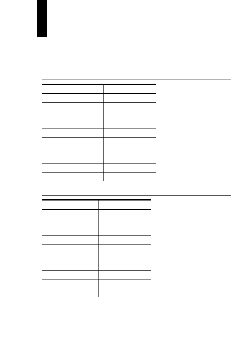
Chapter 7I/O Capabilities
7-2 Visionscape Programmer’s Kit (VSKit) Manual
type, and the index is the zero-based index of the I/O point within the
given type.
How to Use AvpIOClient
To get and set IO values in Visionscape, you will use the AvpIOClient
object. You simply need to instantiate the object, call its
MessengerConnect method to connect it to your chosen Device, and then
call its PointRead and PointWrite methods to read and write I/O values. If
TABLE 7–1. I/O Types and Counts for Host
I/O Type I/O Count
PHYSICAL (GPIO) 16
VIRTUAL 2048
SENSOR 4
STROBE 4
ANALOGOUT 8
SLAVESENSOR 1
TTLINPUT 4
TTLOUTPUT 4
RS422INPUT 4
RS422OUTPUT 4
TABLE 7–2. I/O Types and Counts for Smart Cameras
I/O Type I/O Count
PHYSICAL (GPIO) 8
VIRTUAL 2048
SENSOR 0
STROBE 0
ANALOGOUT 0
SLAVESENSOR 0
TTLINPUT 0
TTLOUTPUT 0
RS422INPUT 0
RS422OUTPUT 0

The AVP I/O Library ActiveX Control
I/O Capabilities
7
Visionscape Programmer’s Kit (VSKit) Manual 7-3
you wish to receive events notifying you of I/O transitions, then you
should declare your AvpIOClient variable using the WithEvents keyword.
The following is sample code demonstrating how you might use the
AvpIOClient:
'declare our variable using WithEvents,
' this allows us to receive the OnTransition event
Private WithEvents m_io As AvpIOClient
Private Sub Form_Load()
'typical app initialization code
…….
'assume m_Dev is the VsDevice reference we are using,
'create and connect our AvpIOClient object to our device
Set m_io = New AvpIOClient
m_io.MessengerConnect m_Dev.Name
End Sub
'a function to pulse Virtual IO point #10
Public Sub GenerateTrigger()
'Turn ON Virtual IO point 1
'passing empty string to PointWrite means
'use first connection
' index is 0 based, so 9 = 10th IO point
' a value of 1 means turn ON the io point
m_io.PointWrite "", AVPIOTYPE_VIRTUAL, 9, 1
' now turn Virtual IO point 1 back off,
' a value of 0 means turn OFF the io point
m_io.PointWrite "", AVPIOTYPE_VIRTUAL, 9, 0
End Sub
'The OnTransition Event
Private Sub m_io_OnTransition(ByVal strName As String, ByVal ioType As
AVPIOLIBLib.AvpIOType, ByVal ioPoint As Long, ByVal newValue As Long)
Dim strMsg As String
'dump a debug msg identifying type, index and state of IO transition
Select Case ioType
Case AVPIOTYPE_PHYSICAL
strMsg = "Physical IO Point "
Case AVPIOTYPE_VIRTUAL
strMsg = "Virtual IO Point "
Case AVPIOTYPE_SENSOR
strMsg = "Sensor Input "
End Select
strMsg = strMsg & ioPoint & IIf(newValue, " Turned On", " Turned Off")

Chapter 7I/O Capabilities
7-4 Visionscape Programmer’s Kit (VSKit) Manual
Debug.Print strMsg
End Sub
As you can see in this example, we instantiated the AvpIOClient object in
the Form_Load event, and connected it to our chosen Device. We
created a GenerateTrigger() sub that will toggle Virtual IO point 10 on and
then off. If your running inspection was set up to be triggered by Virtual IO
point 10, then this routine would, in fact, generate a trigger, and cause
your inspection to run for one cycle. Lastly, we showed the OnTransition
event handler for AvpIOClient. This event passes you the type, index and
state of the IO point that generated the event. We simply put in some
code to dump a message to the Debug window identifying the source of
the transition.
Setting Analog Outputs
The analog outputs on the standard Visionscape GigE Cameras can also
be set programmatically using the AvpIOClient. Simply use the PointWrite
method and specify AVPIOTYPE_ANALOGOUT for the type. You’ll
specify the 0 based index of the analog output just as with the other types
of IO. Lastly, you’ll need to specify the correct value for the PointWrite
method’s newValue parameter. The newValue parameter should be set to
a value in the range of
0 - 63, as the analog outputs have 6-bits of resolution. The Analog
Outputs on the Visionscape GigE Cameras can be varied between 0 and
10 volts. Passing a value of 63 indicates that you want full voltage, or 10
volts. Passing a value of 0 means you want no voltage, or 0 volts. Passing
a value of 32 means you want half voltage, or roughly 5 volts. The
following are some examples:
'set analog output 1 to 0 volts
m_io.PointWrite "", AVPIOTYPE_ANALOGOUT, 0, 0
'set analog output 2 to 5 volts
m_io.PointWrite "", AVPIOTYPE_ANALOGOUT, 1, 32
'set analog output 3 to 10 volts
m_io.PointWrite "", AVPIOTYPE_ANALOGOUT, 2, 63
In the following sections, we will cover all of the properties and methods
of AvpIOClient.

The AVP I/O Library ActiveX Control
I/O Capabilities
7
Visionscape Programmer’s Kit (VSKit) Manual 7-5
Properties
Table 7–3 lists all the available properties of this object in alphabetical
order.
Methods
Table 7–4 lists all the AVP I/O Library methods.
• Function BlockRead(bszName As String, ioType As AvpIOType,
ioPointStart As Long, ioPointEnd As Long)
bszName — Set to an empty string if only connected to one device. If
connected to multiple devices, then specify the name of the device
you want.
ioType —Specifies the type of IO you want to read.
TABLE 7–3. AVP I/O Library Properties
Name Type Description
ConnectionCount Long Returns the number of devices this object has
been connected to via the
MessengerConnect method
TABLE 7–4. AVP I/O Library Methods
Name Description
BlockRead Reads a contiguous block of I/O
BlockSet Sets a contiguous block of I/O to a particular value
BlockWrite Writes a contiguous block of I/O
ConnectionName Returns a specific connection name by index
EnableTransitions Enables/disables transitions for a set of contiguous
I/O points
IsConnected Returns True if the object is connected to the
IOMessenger denoted by name
MessengerConnect Connects to a specific IOMessenger by name
MessengerDisconnect Disconnects from a specific IOMessenger by name
PointRead Reads a specific I/O point
PointWrite Writes a specific I/O point

Chapter 7I/O Capabilities
7-6 Visionscape Programmer’s Kit (VSKit) Manual
ioPointStart — 0 based index of the first IO point in the block to be
read.
ioPointEnd — 0 based index of the last IO point in the block to be
read.
This method reads a contiguous block of I/O from the device
bszName, or from the first device you connected to if bszName is an
empty string. The block’s type is specified by ioType, and the zero-
based range is specified in ioPointStart and ioPointEnd. The method
returns a Variant array of longword values.
Dim vioblock As Variant
'read the state of virtual io 1-10
vioblock = m_io.BlockRead("", AVPIOTYPE_VIRTUAL, 0, 9)
• Sub BlockSet(strName As String, ioType As AvpIOType, ioPointStart
As Long, ioPointEnd As Long, newValue As Long)
The complement to BlockRead, this method sets a contiguous block
of I/O on the device bszName to newValue. If bszName is an empty
string (""), the first connection is used. The type of I/O is given in
ioType, and the zero-based I/O range is given as ioPoinstStart and
ioPointEnd.
'turn ON virtual io 1-10
m_io.BlockSet "", AVPIOTYPE_VIRTUAL, 0, 9, 1
• Sub BlockWrite(bszName As String, ioType As AvpIOType,
ioPointStart As Long, ioPointEnd As Long, val)
This method writes a contiguous set of values in data to the device
bszName, or the first connection if bszName is an empty string. The
I/O type is given as ioType, and the zero-based I/O range is given as
ioPoinstStart and ioPointEnd. The val parameter should be a variant
array of the values you want to write, there must be one value for
each I/O point specified in the range. If the bszName parameter is an
empty string (""), the first connection is assumed.
• Function ConnectionName(nIndex As Long) As String
This method returns the name of the connected IOMessenger,
specified by zero-based nIndex.

The AVP I/O Library ActiveX Control
I/O Capabilities
7
Visionscape Programmer’s Kit (VSKit) Manual 7-7
• Sub EnableTransitions(bszName As String, [bEnable As Long = -1],
[ioType As AvpIOType], [ioPointStart As Long = -1], [ioPointEnd As
Long = -1])
bszName — Pass an empty string to use the first connection;
otherwise, specifies the name of the device.
bEnable — Optional. True when enabling, False when disabling.
ioType — Optional. The type of IO you are specifying.
ioPointStart — Optional. The 0 based index of the first IO point in the
range you are enabling/disabling.
ioPointEnd — Optional. The 0 based index of the last IO point in the
range you are enabling/disabling.
This method can be used to enable transition events only for a limited
range of IO points. Understand that you don’t need to call this method
to receive the OnTransition event, by default, when you call the
MessengerConnect method; transition events will be enabled for all
IO types, across their full range of IO points. Typically, it’s used only
when the user wants to receive events for only a narrow range of IO
points.
• Function IsConnected(bszSystem As String) As Long
This method returns True if the Device bszName is currently
connected to the object.
• Sub MessengerConnect(bszSystem As String)
This method creates a connection to the Device specified by
bszName. Once connected, I/O can be read and written. If your
AvpIOClient object was declared using the WithEvents keyword, then
transition events will be received via the OnTransition event handler,
for all IO types. You do not need to call the EnableTransitions method
to receive the OnTransition event, you need only call that method if
you want to limit the number of IO Transitions you receive.
• Sub MessengerDisconnect(bszName As String)
This method disconnects the object from the Device specified by
bszName.

Chapter 7I/O Capabilities
7-8 Visionscape Programmer’s Kit (VSKit) Manual
• Function PointRead(strName As String, ioType As AvpIOType,
ioPoint As Long) As Long
strName — Specifies the name of the Device you want to talk to.
Pass an empty string to talk to the same Device you passed to
MessengerConnect.
ioType — The type of IO you want to read.
ioPoint — The 0 based index of the IO point you want to read.
This method reads a specific I/O point given by ioType and ioPoint. It
will talk to the same Device name you passed to MessengerConnect
if strName is an empty string. The state of the IO point is returned as
a Long.
Note: Physical I/O points that represent bit values are returned as 0
or 1.
Dim iostate As Long
'read the state of physical IO# 4
iostate = m_io.PointRead("",AVPIOTYPE_PHYSICAL, 3)
• Sub PointWrite(strName As String, ioType As AvpIOType, ioPoint As
Long, newValue As Long)
strName — Specifies the name of the Device you want to talk to.
Pass an empty string to talk to the same Device you passed to
MessengerConnect.
ioType — The type of IO you want to write to.
ioPoint — The 0 based index of the IO point you want to write to.
newValue — The value you wish to write to the IO point.
This method writes a specific I/O point given by ioType and ioPoint to
the Device strName, or to the first Device you connected to if
strName is an empty string. The value is given in newValue.
Note: Physical I/O points that represent bit values are:
set to 0 if newValue is 0
set to 1 if newValue is non-zero

The AVP I/O Library ActiveX Control
I/O Capabilities
7
Visionscape Programmer’s Kit (VSKit) Manual 7-9
'turn ON virtual IO #1
m_io.PointWrite "", AVPIOTYPE_VIRTUAL, 0, 1
'turn OFF Physical IO #9
m_io.PointWrite "", AVPIOTYPE_PHYSICAL, 8, 0
• Function StartVIOTimer(strName As String, nPoint As Long,
intervalMS As Long, [widthMS As Long = 20], [bPulseHigh As Long =
1]) As Long
strName — Specifies the name of the Device you want to talk to.
Pass an empty string to talk to the same Device you passed to
MessengerConnect.
nPoint — The 0 based index of the virtual IO point you want to pulse.
intervalMS — The time in milliseconds between pulses.
widthMS — Optional. The width of each pulse in milliseconds. The
default is 20.
bPulseHigh — Optional. The default is 1, which means the virtual IO
point will be turned On for the length of time specified by widthMS,
then turned Off. Set this to 0 if you wish to reverse the polarity of the
pulse.
This method can be used to pulse a virtual IO point at a set time
interval. For example, you could set virtual IO point 1 to pulse On and
Off every 100ms. Use the optional widthMS parameter to specify how
long the virtual IO point will stay On before being turned Off. The
function returns a timer ID as a long integer that must be passed to
the StopVIOTimer method when you want to shut off the pulses. You
can start up to 4 virtual IO timers simultaneously. This method will
return 0 if it’s unable to start a new timer.
Note: There is a limit of four VIO timers.
• Sub StopVIOTimer([nTimerId As Long = 1])
nTimerID — Optional. The ID of the timer you wish to stop. The
default is 1.
Stops the virtual IO timer specified by the nTimerId parameter.

Chapter 7I/O Capabilities
7-10 Visionscape Programmer’s Kit (VSKit) Manual
Events
Table 7–5 lists all the events of the object.
• Event OnTransition(strName As String, ioType As AvpIOType,
ioPoint As Long, newValue As Long)
This event is fired when a transition has occurred on a specific I/O
point. The name of the device where the transition generated is
strName, the specific I/O point is given as ioType and ioPoint, and the
new value of the point is newValue.
Error Codes
Table 7–6 lists all of the error code values. The error codes listed below
are the low-order word value.
TABLE 7–5. AVP I/O Library Events
Name Description
OnTransition Fired whenever a transition occurs on an I/O point
TABLE 7–6. AVP I/O Library Error Codes
Numeric
Value Name
0x80040BB0 AVPIOCLIENT_E_NOIOCLIENTOBJ
0x80040BB1 AVPIOCLIENT_E_INVALIDARRAY
0x80040C20 IONETMSNGR_E_BADHOSTNAME
0x80040C21 IONETMSNGR_E_CONNECTFAILURE
0x80040C22 IONETMSNGR_E_SOCKETFAILURE
0x80040DC0 IONETCLIENT_E_UNEXPMSG
0x80040E00 IOMSNGR_E_CLIENTNOTFOUND
0x80040E01 IOMSNGR_E_INVALIDSTART
0x80040E02 IOMSNGR_E_INVALIDEND
0x80040E03 IOMSNGR_E_NOOPENDRIVER
0x80040E04 IOMSNGR_E_UNKSYSTEM
0x80040E05 IOMSNGR_E_INVALIDINDEX
0x80040E06 IOMSNGR_E_TYPENOTSUPPORTED

The AVP I/O Library ActiveX Control
I/O Capabilities
7
Visionscape Programmer’s Kit (VSKit) Manual 7-11
0x80040E07 IOMSNGR_E_NOINPUTWRITE
0x80040E08 IOMSNGR_E_CANNOTACCESS
0x80040E09 IOMSNGR_E_UNKTYPE
0x80040E80 IOCLIENT_E_MSNGRNOTFOUND
0x80040E81 IOCLIENT_E_BADTYPEFIELD
TABLE 7–6. AVP I/O Library Error Codes (continued)
Numeric
Value Name

Chapter 7I/O Capabilities
7-12 Visionscape Programmer’s Kit (VSKit) Manual

Visionscape Programmer’s Kit (VSKit) Manual 8-1
8
Display and Setup
Components
8
CHAPTER 8 Display and Setup
Components
Up to this point, most of the information we have provided to you was
related to runtime user interfaces. However, you may also want to provide
setup capabilities in your user interface. The various components
presented in this chapter will allow you to easily provide users with the
ability to adjust tool parameters and ROI positions (Setup Manager),
acquire single images or live video (Setup Manager again), view or edit
the Job tree (Job Manager), or provide more specialized capabilities. We
also present our primary Image display component, the Buffer Manager
control, which can be used to display any kind of image buffer from any
Step or Report Connection. Buffer Manager can be used along with a
Report Connection to display runtime images, or it can be used to display
a Step's output buffer at Setup time. The following are the ActiveX
Controls we will cover in this chapter:
• “Buffer Manager ActiveX Control” on page 8-2
• “Setup Manager ActiveX Control” on page 8-14
• “Job Manager ActiveX Control” on page 8-40
• “Datum Grid Active X Control” on page 8-51
• “StepTreeView ActiveX Control” on page 8-54
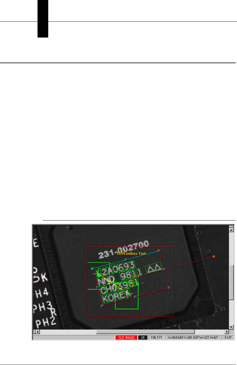
Chapter 8Display and Setup Components
8-2 Visionscape Programmer’s Kit (VSKit) Manual
Buffer Manager ActiveX Control
The Buffer Manager ActiveX Control allows you to view the contents of an
image buffer and optionally view and position vision tools. You may
remember that we used this component to display our images in the
chapter on Report Connections (Chapter 6). Add the following
Component to your project to access Buffer Manager:
+Visionscape Controls: Buffer Manager
Although this component does provide the capability to graphically
manipulate tool search areas (ROIs), and tool status graphics, you would
typically use Buffer Manager to display images only. Use the Setup
Manager component when you want your user to be able to make
adjustments to the loaded Job (move ROIs, change parameters, acquire
images and live video). The Buffer Manager displays Buffer Datums,
which are represented in Visionscape by the BufferDm object. The Buffer
Manager can be connected to any BufferDm in a job, and its window will
then display that buffer’s contents. The default display shows the buffer
with scroll bars, as necessary. The image also contains overlaid graphics
positioning vision tools. Figure 8–1 shows an example of the Buffer
Manager.
FIGURE 8–1. Buffer Manager — Example
Buffer Manager ActiveX Control
Display and Setup
Components
8
Visionscape Programmer’s Kit (VSKit) Manual 8-3
The Buffer Manager also contains a status bar that flanks the bottom of
the control, as shown in Figure 8–2.
FIGURE 8–2. Buffer Manager Status Bar
This status bar displays the following:
• The first pane displays the image file name (if image files are being
used).
• The second pane is either blank, displays OLD IMAGE in red if the
image being displayed is not current, or WAITING… if the current
tryout or acquisition is waiting for a trigger signal to continue.
• The third pane shows the gray-scale pixel value under the current
mouse position.
• The fourth pane shows the current mouse position.
• The fifth pane shows size information of the ROI of the current tool.
• The last pane shows the rotational angle of the current tool.
Context Menu
The Context Menu, as shown in Figure 8–3, provides access to Buffer
Manager functionality. All functions are provided to a programmer through
the control's methods. To access the Context Menu, right-click the mouse
button.
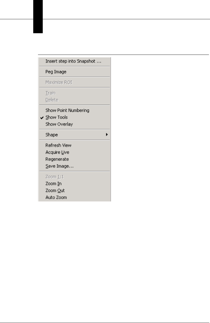
Chapter 8Display and Setup Components
8-4 Visionscape Programmer’s Kit (VSKit) Manual
FIGURE 8–3. Context Menu
The Context Menu provides the following functionality:
• Maximize ROI — Enabled when you click on a tool. Selecting this
item causes the ROI to be as large as the image itself.
• Train — Trains the selected ROI.
• Delete — Deletes the selected ROI.
• Show Tools — When selected, tool graphics are displayed.
• Show Overlay — When selected, shows the graphical overlay.
• Shape — Allows you to show or hide specific shapes as well as zoom
to a specific shape.
• Refresh View — Redraws the view.

Buffer Manager ActiveX Control
Display and Setup
Components
8
Visionscape Programmer’s Kit (VSKit) Manual 8-5
• Acquire Live — When selected, acquires live images from the
camera.
• Regenerate — Acquires a new image.
• Save Image… — Allows you to save the current image to disk as
either TIFF or BMP.
• Zoom menu items — Changes portion and resolution of the image
currently being displayed. Items include: Zoom 1:1, Zoom In, Zoom
Out.
Displaying an Image
As we said above, the Buffer Manager displays BufferDm objects. Every
Step that produces an output buffer in Visionscape will present that buffer
to your program in the form of a BufferDm object. Likewise, the report
connection objects, when uploading images, will always package those
images in BufferDm objects. To display a BufferDm in the Buffer
Manager, you simply pass it's Handle property to the Buffer Manager's
Edit method. The following example shows how you would display an
image returned by the AvpReportConnection object.
Private Sub m_conn_OnNewReport(ByVal rptObj As AVPREPORTLib.IAvpInspReport,
ByVal bGoingToFreeze As Boolean)
Dim buf As BufferDm
If rptObj.Images.Count > 0 Then
'get the bufferdm out of the Images collection
Set buf = rptObj.Images(1)
'display the image in our Buffer Manager Control
' pass in the handle of our BufferDm,
' second param is always 0
ctlBufMgr.Edit buf.Handle, 0
End If
End Sub

Chapter 8Display and Setup Components
8-6 Visionscape Programmer’s Kit (VSKit) Manual
Properties
Table 8–1 lists the Buffer Manager control properties.
TABLE 8–1. Buffer Manager Control Properties
Name Description
Appearance When 1, the control is drawn with a 3D effect.
AutoZoom When True, the displayed buffer is sized to fit the window.
BackColor Specifies the background color of the window.
BorderStyle Specifies whether or not the control displays a border
BufferDm Returns the handle to the currently displayed Buffer Datum.
BufferHeight Returns the height of the current buffer.
BufferWidth Returns the width of the current buffer.
EnableContextMenu When True, the right-click context menu is available to the user.
EnableEditGraphics When True, edit-time graphics are displayed.
EnableRunGraphics When True, runtime graphics after a tryout are displayed.
EnableToolMovement When True, tool movements are enabled.
ScrollPositionX The x-coordinate of the top left scroll position.
ScrollPositionY The y-coordinate of the top left scroll position.
SelectedTool The handle of the currently selected tool.
ShowOverlay When True, the overlay graphics are displayed.
ShowSplitScrolls When True, the scroll bars (with splitting capabilities) are displayed.
ShowStatusBar When True, the status bar at the bottom is displayed.
StepTipDelay Mouse inactivity delay in msec of the Step “tooltip” time.
ZoomFactor The zoom factor for the display.
Buffer Manager ActiveX Control
Display and Setup
Components
8
Visionscape Programmer’s Kit (VSKit) Manual 8-7
Methods
Figure 8–2 lists the Image Display methods.
Figure 8–3 lists the Functionality Methods.
TABLE 8–2. Image Display Methods
Name Description
Edit Defines the buffer to be shown.
OpenImage Opens a given .tif into the current buffer datum.
SaveCurrentImage Saves the current buffer display to a .tif.
ScrollTo Displays the image with the input point at the upper left corner.
ZoomIn Magnifies a portion of the image.
ZoomOut Displays the image at a lower resolution.
ZoomTo Displays the image at a specific resolution.
TABLE 8–3. Buffer Manager Functionality Methods
Name Description
DimActiveMenuItems Dims the Train, Delete, Next, Prev, Live, and Regenerate context-
menu options.
OffscreenDCGet Returns a handle to the off screen device context, which can be
used for drawing, using standard Win32 GDI APIs.
OffscreenDCRelease Releases the handle to the off screen device context and optionally
redraws the screen.
OffscreenDCSave Saves the current image with graphics as a bitmap file
PixelBufToCtrl Converts a given set of pixels in buffer space to the control's client
space.
PixelCtrlToBuf Converts a given set of pixels in the control's client space to buffer
space.
RefreshView Redraws image and graphics without regenerating.
Regenerate Runs a PostRun/Prerun on the entire job and optionally takes
pictures for each snapshot.
SetUIMode Sets up the Buffer Manager control in Normal, Wizard, Setup, or
Tryout modes. These modes correspond to modes in the Setup
Manager ActiveX control.
Chapter 8Display and Setup Components
8-8 Visionscape Programmer’s Kit (VSKit) Manual
Figure 8–4 lists the Overlay Drawing methods.
• Sub ClearOverlay()
This method clears the overlay buffer.
Return Values - None.
• Sub CrossAt(x As Double, y As Double, size As Integer)
This method draws a cross at the given (x,y) location using size as
the pixel width of the cross legs.
Return Values - None.
TABLE 8–4. Buffer Manager Overlay Drawing Methods
Name Description
ClearOverlay Clears the overlay buffer completely
CrossAt Draws a cross at the given location in the current pen color
Ellipse Draws a filled ellipse at the given location in the current pen and given fill
color.
EllipseFilled Draws an ellipse at the given location in the current pen.
LineTo Draws a line from the current location to the given locations in the current
pen color
MoveTo Moves the current location
Rectangle Draws a rectangle at the given location using the current pen
RectangleFilled Draws a filled rectangle at the given location in the current pen and given fill
color
SetBkColor Sets the current background color
SetBkMode Sets the background mode to either opaque or transparent
SetPenColor Set the current pen color
SetTextColor Sets the current text color
TextOut Draws text in the overlay using the current text and background colors and
background mode

Buffer Manager ActiveX Control
Display and Setup
Components
8
Visionscape Programmer’s Kit (VSKit) Manual 8-9
• Function DimActiveMenuItems(bDim As Integer) As Long
This method dims the Train, Delete, Next, Prev, Live, and Regenerate
context-menu options the next time the context menu is displayed.
This blocks you from modifying tools and buffers from the menu.
Return Values - 0 if successful, non-zero if fail.
• Function Edit(hBufferDm As Long, userMode As Integer) As Long
This method takes a handle to a buffer datum and displays the buffer.
The userMode should be set to 0.
Return Values - 0 if successful, non-zero if fail.
• Sub Ellipse(x1 As Double, y1 As Double, x2 As Double, y2 As
Double)
This method draws an ellipse in the overlay in the rectangle specified
as (x1,y1) to (x2,y2). The ellipse is drawn in the current pen.
Return Values - None.
• Sub EllipseFilled(x1 As Double, y1 As Double, x2 As Double, y2 As
Double, crFill As OLE_COLOR)
This method draws a filled ellipse in the overlay in the rectangle
specified as (x1,y1) to (x2,y2). The ellipse is drawn in the current pen
with the given fill color.
Return Values - None.
• Sub LineTo(x As Double, y As Double)
This method draws a line in the overlay from the current location to
the location (x,y) using the current pen. Use this method together with
the MoveTo method.
Return Values - None.

Chapter 8Display and Setup Components
8-10 Visionscape Programmer’s Kit (VSKit) Manual
• Sub MoveTo(x As Double, y As Double)
This method moves the current position in the overlay to location
(x,y). Use this method together with LineTo to draw lines in the
overlay buffer.
Return Values - None.
• Function OffscreenDCGet() As Long
This method returns a handle to the off screen device context of the
current buffer. This handle can be passed to Win32 GDI APIs in order
to perform custom drawing. This is the same DC that draw runtime
graphics. As a result, any drawing on this DC will alter existing
runtime graphics. Callers must then call OffscreenDCRelease to
release the handle and redraw the image.
• Sub OffscreenDCRelease([drawNow As Boolean = True])
This method releases the offscreen device context and optionally
redraws the image. Callers must first call OffscreenDCGet before
retrieving the handle to this method.
• Sub OffscreenDCSave(bmpFileName As String)
This method saves the current image with all graphics as a bitmap
file.
• Function OpenImage(strFileName As String) As Long
This method opens the given file name into the current BufferDm.
Return Values - 0 if successful, non-zero if fail.
• Sub PixelBufToCtrl(xPixel As Integer, yPixel As Integer)
This method converts given pixel values in the buffer space to the
control's client space. Zooming and scrolling are taken into effect.
• Sub PixelCtrlToBuf(xPixel As Integer, yPixel As Integer)
This method converts given pixel values in the control's client space
to buffer space. Zooming and scrolling are taken into effect.

Buffer Manager ActiveX Control
Display and Setup
Components
8
Visionscape Programmer’s Kit (VSKit) Manual 8-11
• Sub Rectangle(x1 As Double, y1 As Double, x2 As Double, y2 As
Double)
This method draws a rectangle in the overlay as defined from (x1,y1)
to (x2, y2), using the current pen.
Return Values - None.
• Sub RectangleFilled(x1 As Double, y1 As Double, x2 As Double, y2
As Double, crFill As OLE_COLOR)
This method draws a filled rectangle in the overlay in the rectangle
specified as (x1,y1) to (x2,y2). The rectangle is drawn in the current
pen with the given fill color.
Return Values - None.
• Sub RefreshView()
This method redraws the image and graphics without regenerating.
• Sub Regenerate(bAcquire As Boolean)
This method regenerates the current Buffer Datum and optionally
takes a picture. If the target is running any inspections, the call fails
and a STEPLIB error code is thrown to the caller.
• Function SaveCurrentImage(strFileName As String) As Long
This method saves the current image to the given file name. When
the file name ends with the .bmp extension, the image is saved in
Bitmap format. Otherwise, the image is saved as a .tif.
Return Values - 0 if succesful, non-zero if fail.
• Function ScrollTo(x As Long, y As Long) As Long
This method causes the Buffer Manager to show the image with the
input point (x,y) at the upper left corner of the view.
Return Values - 0

Chapter 8Display and Setup Components
8-12 Visionscape Programmer’s Kit (VSKit) Manual
• Sub SetBkColor(red As Integer, green As Integer, blue As Integer)
This method sets the background color used to draw text in the
overlay to the given RGB (0-255 each). The color is used only if the
background mode is set to opaque (2).
Return Values - None.
• Sub SetBkMode(mode As Integer)
This method sets the background mode used to draw text in the
overlay. The mode is either transparent (1) or opaque (2).
Return Values - None.
• Sub SetPenColor(red As Integer, green As Integer, blue As Integer)
This method sets the current pen color to the given RGB. Each value
range is 0-255.
Return Values - None.
• Sub SetTextColor(red As Integer, green As Integer, blue As Integer)
This method sets the current text color to the given RGB. Each value
range is 0-255. This color is used when TextOut is called.
Return Values - None.
• Function SetUIMode(mode As Integer) As Long
This method selects Normal, Wizard, Setup, or Tryout mode. These
modes, which correspond to modes in the Setup Manager ActiveX
Control, modify the functionality available in the Buffer Manager
control.
Return Values - 0 if succesful, non-zero if fail.
• Sub TextOut(x As Double, y As Double, text As String)
This method draws the given text at the given (x,y) location in the
buffer using the current text color, background color, and background
mode.
• Sub UpdateWindow()

Buffer Manager ActiveX Control
Display and Setup
Components
8
Visionscape Programmer’s Kit (VSKit) Manual 8-13
This method redraws the window.
Return Values - None.
• Function ZoomIn() As Long
This method magnifies the image shown in the Buffer Manager and,
as a result, shows less of the image at a higher resolution.
Return Values - 0
• Function ZoomOut() As Long
This method causes the Buffer Manager to show more of the image at
a lower resolution.
Return Values - 0
• Function ZoomTo(scaleNumerator As Integer, scaleDenominator As
Integer) As Long
This method causes the Buffer Manager to show the image at the
resolution specified by the input ratio.
Return Values 0
Events
Figure 8–5 lists the events of the Buffer Manager.
TABLE 8–5. Buffer Manager Events
Name Description
KeyDown Standard stock event
KeyPress Standard stock event
KeyUp Standard stock event
LiveModeChanged Fired when the Live Mode is changed.
MouseDown Standard stock event*
MouseMove Standard stock event*
MouseUp Standard stock event*
ToolInserted Fired when the user inserts a tool in the image. The handle of the tool
is sent.

Chapter 8Display and Setup Components
8-14 Visionscape Programmer’s Kit (VSKit) Manual
Error Codes
Figure 8–6 lists the error code values. The error codes are low-order word
values.
Setup Manager ActiveX Control
The Setup Manager ActiveX Control provides an integrated operator
setup environment. The Setup Manager allows the user to position and
train vision tools, to test their inspections by using the tryout capability,
and also allows the user to acquire images and live video. Add the
following Component to your project to access Setup Manager:
+Visionscape Controls: Setup Manager
The Setup Manager can be used as a self-contained setup environment
or as a component within the user interface. It can be controlled from
Visual Basic by using its full range of methods, events, and properties.
The built-in user interface's components can be disabled or hidden so that
a programmer can develop a unique user interface. The properties
ToolMoved Fired when a tool is moved. The handle to the tool is also sent.
ToolRegenerated Fired when the current tool is regenerated. The handle of the tool is
sent.
ToolSelected Fired when a tool is selected. The handle to the tool is also sent.
ToolToBeDeleted Fired when you select Delete from the context menu to delete a tool.
ToolTrained Fired when a tool is trained. The handle to the tool is also sent.
TABLE 8–6. Buffer Manager Error Codes
Name Numeric Value
S_OK 0h
E_FAIL 80004005h
BUFMGR_E_NOBUFDM 80040501h
BUFMGR_E_NOOFFSCREENDC 80040502h
BUFMGR_E_NOBUFVIEW 80040503h
TABLE 8–5. Buffer Manager Events (continued)
Name Description

Setup Manager ActiveX Control
Display and Setup
Components
8
Visionscape Programmer’s Kit (VSKit) Manual 8-15
ShowToolbar, ShowProperties, and ShowItemList can be used to display
or hide the Toolbar, the list of steps to set up (Item Checklist), and/or the
Tool properties page.
Random Access vs. Wizard Mode
The Setup Manager ActiveX Control contains two main operating modes:
• Random Access — This is the default. The user is permitted to select
any item in the setup checklist at any time, which then selects the
applicable vision tool in the image display area. In addition, the
properties area displays settings for the currently selected item.
All user modifiable shapes are visible in the image display area and
can be randomly selected, sized, and moved.
• Wizard Access — The Setup Manager transfers to the Wizard Mode
through the WizardStart() API. In this mode, you must visit every item
in the setup checklist at least once. An arrow appears to the left of the
first item in the checklist indicating that this is the current item
requiring setup. The user must either click the Next Item button in the
Toolbar, or call the NextItem() API to move the cursor to the next list
item. If the tool requires training and has never been previously
trained, you are not permitted to step to the next item until you have
completed training. As a final check, the current setup item is
automatically executed and must pass before continuing to the next
step. After the last step is reached and successfully set up, the Next
Item button in the Toolbar changes to a checkmark, which signifies
the Finish command. The user can either click Finish or call the
WizardFinish() API to return to the Setup Manager random access
mode.
Only the shapes associated with the current setup item are displayed. All
other shapes are hidden. The user is only permitted to size and move the
visible shapes.
Tryout Mode
Once an application has been successfully set up, Setup Manager
provides methods to perform a trial run, or tryout, on the application. By
using the Toolbar buttons or calling APIs, you can start, stop, and pause
running the application. As the application runs, the various displays show
the step currently in progress. The user may also set various tryout
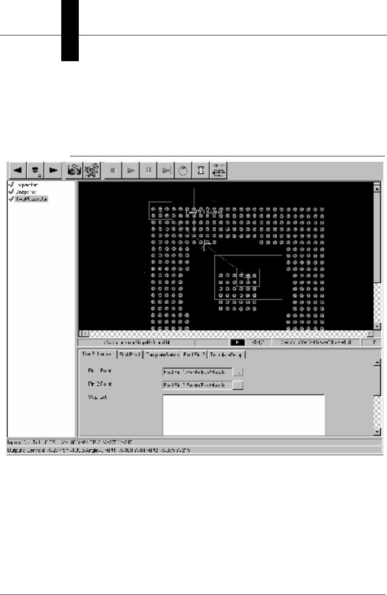
Chapter 8Display and Setup Components
8-16 Visionscape Programmer’s Kit (VSKit) Manual
options. For example, you might have the application automatically pause
on failures.
Figure 8–4 shows an example of the Setup Manager ActiveX Control.
FIGURE 8–4. Setup Manager Window — Example
Toolbar
The Toolbar, as shown in Figure 8–5, is the Setup Manager's main user
interface. It contains buttons for acquiring images through live video,
training the subject, and setting up and trying out the inspection.
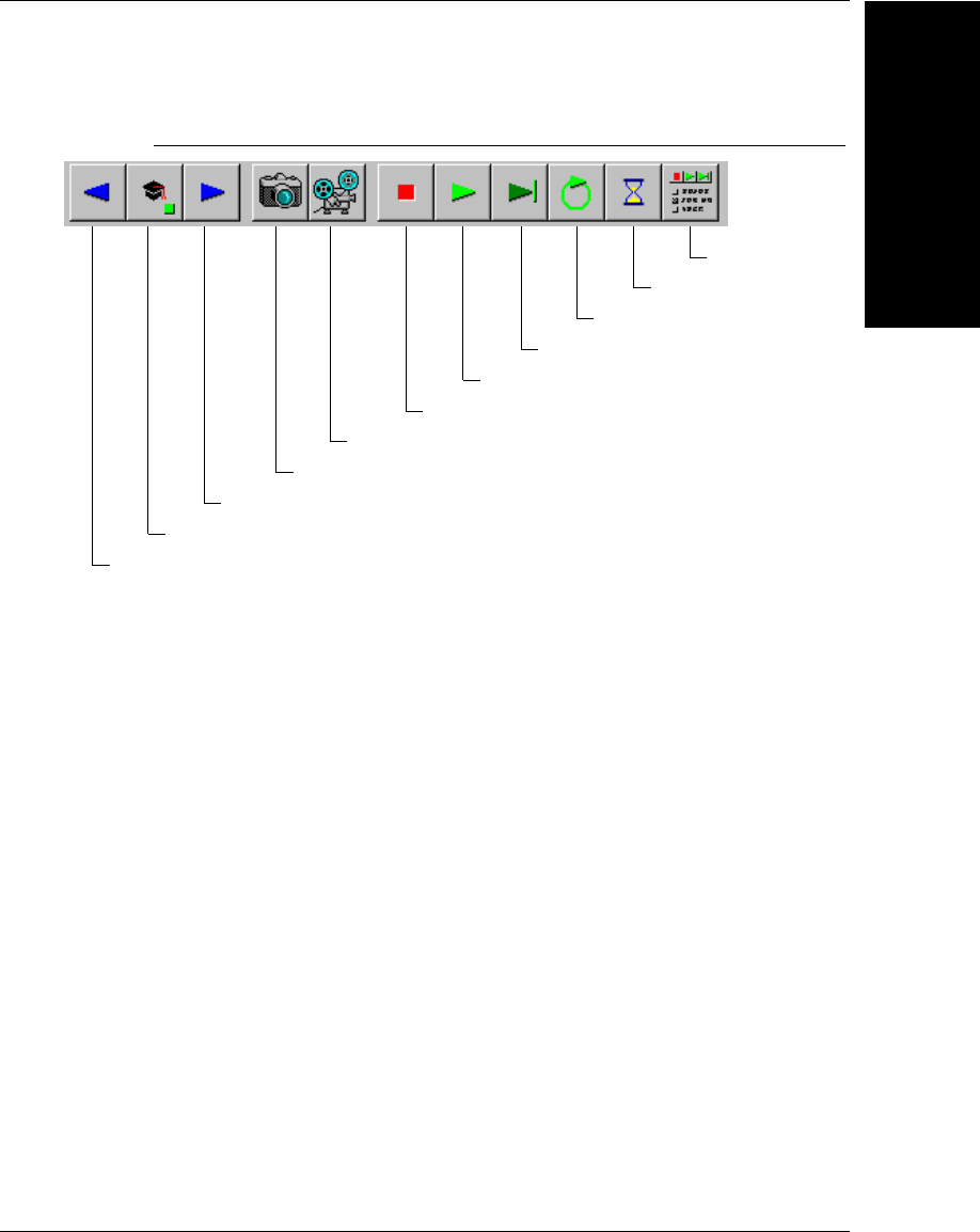
Setup Manager ActiveX Control
Display and Setup
Components
8
Visionscape Programmer’s Kit (VSKit) Manual 8-17
FIGURE 8–5. Setup Manager Toolbar
Step and Train Buttons
The first and third buttons from the left allow you to Step Backward or
Step Forward through the list of Setup Items. The left arrow is disabled
when you are at the first item in the train sequence. Conversely, the right
arrow is disabled when you are at the last item. If the current step requires
training, the right arrow is disabled and the Train button (second from left)
is enabled. The user must position the tool appropriately (in the image
view) and then click the Train button. The square on the Train button
turns red when the tool is not trained, and green when the tool is trained.
The button turns yellow specifically for statistical tools, indicating that
there have not been enough acquired samples to allow the tool to run
even though the tool has been trained.
Acquire Buttons
The next two buttons, as shown in Figure 8–6, allow you to acquire a new
image.
Train
Live Video
Acquire Image
Step Backward
Step Forward
Start Tryout
Try Current Tool
Tryout Settings
Stop Tryout
Delay
Loop
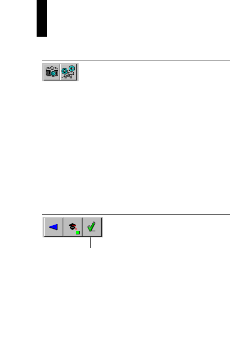
Chapter 8Display and Setup Components
8-18 Visionscape Programmer’s Kit (VSKit) Manual
FIGURE 8–6. Acquire Buttons
The Acquire Image button takes a single new image from the current
camera. If triggers are active in the Acquire Step, the acquisition will not
occur until the trigger signal occurs. If after ½ a second the trigger has not
occurred, a “Waiting For Trigger” box appears allowing you to cancel the
acquisition.
The Live Video button continuously acquires new images until clicked
again. Triggers and sensors are used with Live Video.
Wizard Training Complete
After you have reached and trained the last item in the list, the right arrow
changes to a check mark as shown in Figure 8–7.
FIGURE 8–7. Trained — Check Mark
This signifies that the wizard-training mode is complete. Then, the user
clicks the Check button to conclude the training mode.
Tryout Buttons
The next set of buttons, as shown in Figure 8–8, are used for running the
job on the host.
Live Video
Acquire Image
Wizard Training Complete
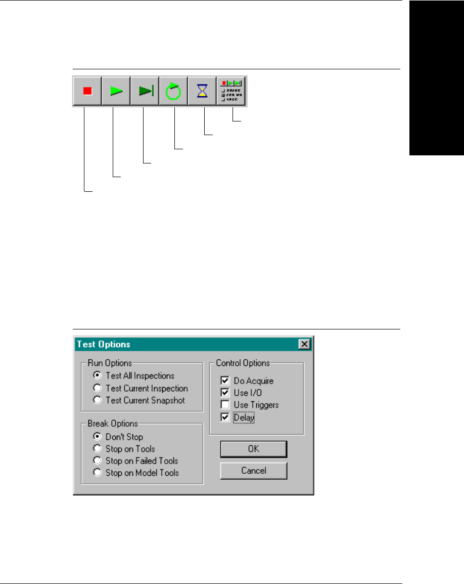
Setup Manager ActiveX Control
Display and Setup
Components
8
Visionscape Programmer’s Kit (VSKit) Manual 8-19
FIGURE 8–8. Tryout Buttons
These buttons allow you to tryout the application on the host PC to ensure
that the application works correctly. Click Start Tryout to run through the
application, showing the result of each step of the application in order.
Click Try Current Tool to run the currently selected tool only. Click Stop
Tryout to stop the tryout at any time.
Click Tryout Settings to display the Tryout Options dialog box, as shown
in Figure 8–9.
FIGURE 8–9. Tryout Options Dialog Box
This dialog box allows you to set optional tryout behavior:
• Run Options — Determines which steps run when a tryout is
performed. The choices include Test All Inspections, Test Current
Inspection, and Test Current Snapshot.
Start Tryout
Try Current Tool
Tryout Settings
Stop Tryout
Delay
Loop

Chapter 8Display and Setup Components
8-20 Visionscape Programmer’s Kit (VSKit) Manual
• Break Options — Determines under which circumstances the tryout
stops. The choices include:
– Don't Stop — Running through the entire setup list without
stopping
– Stop On Tools — Stopping on each tool in turn
– Stop On Failed Tools — Stopping on tools that have failed their
vision processing
– Stop On Model Tools — Stopping on statistical tools. This option
allows you to train additional samples for these tools.
• Control Options — Determine whether to:
– Acquire images by selecting Do Acquire
– Use I/O
– Continuously Loop during tryout (by default tryout will run through
once)
– Delay, meaning pause briefly between tools in order to better
view the resulting graphics
Image Display
Image Display and tool editing are handled by an embedded Buffer
Manager ActiveX Control. Refer to “Buffer Manager ActiveX Control” on
page 8-2 for more information.
Tool Properties Display
Editing of the Tool Properties Display is handled by an embedded Datum
Manager ActiveX Control. Refer to “Datum Manager ActiveX Control” on
page B-11 for more information.
Setup Item Checklist
The Setup Item Checklist, as shown in Figure 8–10, represents the steps
within the job that have previously been designated as operator setup
steps.
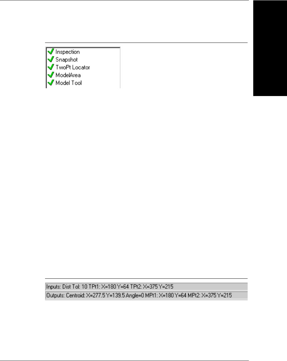
Setup Manager ActiveX Control
Display and Setup
Components
8
Visionscape Programmer’s Kit (VSKit) Manual 8-21
FIGURE 8–10. Setup Item Checklist
By default, the Setup Item Checklist includes the Inspection Step, any
Snapshot steps, and related vision tools. The list can be used in
conjunction with the Setup Manager's Wizard Training Mode to prompt
you through each required step in the setup process. When a checklist
item is highlighted, press the Next Item button or call the NextItem
ActiveX Control method. This ensures that the current step functions,
guarantees that it passes when run, and then leads to the next step.
Some checklist items require training. These items are identified by a
small square to the left of the item. When the square is red, the item is
untrained and cannot be run. When the square is green, the item has
been successfully trained and can be run. When in Wizard Mode, each
item is graphically checked off when completed. In tryout, each item
includes either a green checkmark signifying that it passed, or a red X
signifying that it failed.
Status Bar
The Status Bar, as shown in Figure 8–11, includes two information areas:
• Inputs — Shows tool specific information about the inputs to the tool.
• Outputs — Shows tool specific information on the outputs generated
by the tool.
FIGURE 8–11. Setup Manager Status Bar
Using Setup Manager in your Application
Using the Setup Manager control in your application is fairly straight
forward, but there are several key points that you should understand.

Chapter 8Display and Setup Components
8-22 Visionscape Programmer’s Kit (VSKit) Manual
1. You Must Have a Job Loaded in Memory
You use Setup Manager by connecting it to the currently loaded Job. This
means you should be familiar with the concepts covered in Chapter 2,
and understand how to load an AVP file into a JobStep object.
2. Connect Setup Manager to your Job via the Edit Method
The Edit method is used to connect the control to one of the Steps in your
Job. Setup Manager can be connected to the VisionSystem step, or a
Snapshot Step, but generally it makes the most sense to connect to an
Inspection Step. FrontRunner for example always connects it's Setup
Manager to Inspection Steps. The following is a simple example that
loads a Job, finds the inspection steps, and then connects a Setup
Manager control (named ctlSetup in this example) to the first Inspection
step in the Job:
Private m_job As JobStep
Private m_vs As VisionSystemStep
Private m_coord As VsCoordinator
Private m_dev As VsDevice
Private Sub Form_Load()
'instantiate our objects
Set m_coord = New VsCoordinator
Set m_job = New JobStep
'get the first available device
Set m_dev = m_coord.Devices(1)
'load our sample job
m_job.Load "C:\Vscape\Tutorials &
Samples\Sample Jobs\ProgSample_MultiCam.avp"
Set m_vs = m_job(1) 'get first VisionSystem step
'connect job to hardware
m_vs.SelectSystem m_dev.Name
'find all the inspection steps in the job
Dim colInsp As AvpCollection, insp As Step
Set colInsp = m_vs.FindByType("Step.Inspection")
'connect our Setup Manager to the first inspection
Set insp = colInsp(1)
ctlSetup.Edit insp.Handle, 0

Setup Manager ActiveX Control
Display and Setup
Components
8
Visionscape Programmer’s Kit (VSKit) Manual 8-23
End Sub
3. Disconnect Setup Manager When Using Other Controls
The previous example illustrated an application that simply loaded a Job
and connected it to Setup Manager. This is obviously not a practical
application, and does not represent how you are most likely going to use
Setup Manager. Typically Setup Manager is used when the developer
wishes to provide both Runtime and Setup capabilities within their UI. In
that scenario, your UI should provide some type of control (a button,
toolbar button, etc.) that allows the UI to switch from Run Mode to Setup
Mode, and vice versa. It’s important to understand that when switching to
Run Mode, where you will be connecting runtime components such as
VsRunView or Runtime Manager, you must disconnect Setup Manager
first. Like wise, when your application switches from Run Mode back to
Setup Mode, you should disconnect your Runtime components first
before connecting Setup Manager. YOUR APPLICATION MAY CRASH IF
YOU DO NOT FOLLOW THIS RULE. Disconnect Setup Manager by
passing a 0 for the Step handle, like this:
ctlSetup.Edit 0, 0
The following Visionscape Controls should always be disconnected
before connecting Setup Manager, and Setup Manager should always be
disconnected before connecting any of them:
• VsRunView
• Runtime Manager
• Job Manager
4. Always Disconnect Before Deleting Your Job
If Setup Manager is connected to your currently loaded Job, and you
delete it, bad things can happen. This generally applies to two scenarios:
• Your deleting the current Job in order to load a new Job.
• Your application is closing down.
In each of these scenarios, your application could crash if you don't
disconnect Setup Manager. So, when changing Jobs, always disconnect

Chapter 8Display and Setup Components
8-24 Visionscape Programmer’s Kit (VSKit) Manual
Setup Manager first. When your application closes down, remember to
disconnect Setup Manager in your Form_Unload logic.
5. You May Only Use One Setup Manager Control
Multiple Setup Manager controls in the same application will conflict with
each other if they are ever connected at the same time. This is not
allowed. If your application will load a Job that contains multiple
Inspection Steps, and you want Setup Manager to be able to connect to
any of those inspections, then you should do what FrontRunner does.
Provide a list of all the Inspections in the loaded Job to your user, and
allow them to choose one at a time. Your application would then connect
your Setup Manger to the chosen Inspection via the Edit method.
6. Setup Manager Works With Step Handles
Throughout this manual we have talked about the Step object and how to
use it. You should understand that the Setup Manager does not deal with
the Step object directly, it instead deals with Step handles. Have no fear,
the conversion is quite easy.
• When Passing Step Handle to Setup Manager: The Step Object has
a Handle property, so this is quite easy to provide.
• When Setup Manager returns a Step Handle to you, what do you do
with it? A Step Handle can be converted to a Step object by using the
AvpHandleConverter object. As an example, if you used the Setup
Manager's GetCurrentStep function to get the step that is currently
selected, this would return a Step Handle to you. The following
example shows you could then convert that handle to a Step Object:
Dim hc As New AvpHandleConverter
Dim selStep As Step, hStep As Long
hStep = ctlSetup.GetCurrentStep
If hStep <> 0 Then
Set selStep = hc.AvpObject(hStep)
Debug.Print "Selected Step is " & selStep.Name
End If
7. Setup Manager’s Appearance is Customizable
By default, Setup Manager presents you with a built in toolbar that can be
used for trying out the inspection, acquiring images, live video, etc. If you
don't like this toolbar, you can easily hide it and create your own. All of the
functionality provided by this toolbar is exposed via the methods of Setup

Setup Manager ActiveX Control
Display and Setup
Components
8
Visionscape Programmer’s Kit (VSKit) Manual 8-25
Manager. So, you can easily create your own toolbar, and only allow the
user access to the features you want them to have. Refer to the following
sections for more info on the available properties and methods of Setup
Manager.
Properties
Figure 8–7 lists all the available control properties of the Setup Manager.
TABLE 8–7. Setup Manager Control Properties
Name Type Description
AcquireStatus Boolean Returns True when the current image
acquisition has completed.
AllowMouseToolInsertion Boolean When True, you can insert tools in the
image by click-n-drag.
AutoRegenerate Boolean When True, tools are automatically
regenerated whenever moved, sized, or
have parameters changed.
AutoRetrain Boolean When True, setup tools are automatically
regenerated whenever moved, sized, or
have parameters changed.
BackColor OLE_COL OR Specifies the background color of the
embedded Buffer Manager.
BufMgr BufMgr reference Returns a reference to the embedded
Buffer Manager control. Callers can
retrieve this interface and call methods of
the embedded Buffer Manager.
EnableContextMenu Boolean Buffer Manager: When True, the right-click
context menu of the contained Buffer
Manager is usable.
EnableEditGraphics Boolean When True, edit objects are displayed in
the image allowing you to edit/move tools.
EnableInspErrorStatusBar Boolean When True, an error status bar is displayed
whenever a tool generates an execution
error.
EnableRunGraphics Boolean When True, runtime graphics are displayed
in the image.
EnableToolMovement Boolean Buffer Manager: When True, tools in the
contained Buffer Manager are moveable.

Chapter 8Display and Setup Components
8-26 Visionscape Programmer’s Kit (VSKit) Manual
Methods
The following tables list the Setup Manager methods:
• Table 8–8, “Control Initialization Methods”
• Table 8–9, “General Training Methods”
• Table 8–10, “Image Capture Methods”
• Table 8–11, “Image Methods”
• Table 8–12, “Information Methods”
• Table 8–13, “Item Selection Methods”
ImageViewPercentage long Returns/sets the percentage of the window
used for the Image View display. The effect
of this percentage depends on where the
Properties are displayed (right or bottom)
PropertiesAtBottom Boolean When True, the Properties View is
displayed underneath the Image View.
When False, the Properties View is
displayed to the right of the Image View.
SetupListPercentage long Returns/sets the percentage of the window
used for the display of the Setup List
ShowBufStatusBar Boolean When True, the Status Bar of the
embedded Buffer Manager is displayed.
ShowItemList Boolean Determines whether the Item List view
pane is visible.
ShowProperties Boolean Determines whether the Tool Properties
(Datum View) pane is visible.
ShowStatusBar Boolean When True, the status bars are displayed.
ShowToolbar Boolean Determines whether Toolbar is visible.
StatusInputString String Inputs text displayed in the Status Bar.
StatusOutputString String Outputs text displayed in the Status Bar.
StepTipDelay Integer Delay (in msec) used when displaying step
tool tips.
TABLE 8–7. Setup Manager Control Properties
Name Type Description

Setup Manager ActiveX Control
Display and Setup
Components
8
Visionscape Programmer’s Kit (VSKit) Manual 8-27
• Table 8–14, “Tryout Methods”
TABLE 8–8. Control Initialization Methods
Name Description
Edit Prepares the Setup Manager to set up an application.
RefreshView Redraws the Buffer Manager window.
TABLE 8–9. General Training Methods
Name Description
TrainCurrentItem Trains the current checklist item.
TrainCurrentShape Trains the currently selected shape in the BufMgr.
TrainItem Trains the checklist item specified.
TrainShape Trains the given shape.
TABLE 8–10. Image Capture Methods
Name Description
Acquire Captures a new image.
AcquireStop Halts an asynchronous image acquisition.
LiveVideo Turns live image display On and Off.
PixelBufToCtrl Similar to the Buffer Manager API, but the control's
client space is the SetupMgr, not the BufMgr.
PixelCtrlToBuf Similar to the Buffer Manager API, but the control's
client space is the SetupMgr, not the BufMgr.
Regenerate PostRun/PreRun the entire job and optionally captures
a picture.

Chapter 8Display and Setup Components
8-28 Visionscape Programmer’s Kit (VSKit) Manual
TABLE 8–11. Image Methods
Name Description
ImageTackCurrent Tacks the current image. When tacked, the image
does not change as you step through the item list.
ImageUntackCurrent Untacks the current image. When untacked, the
displayed image changes as you step through the
item list.
ScrollTo Exposed Buffer Manager API
ZoomIn Exposed Buffer Manager API
ZoomOut Exposed Buffer Manager API
ZoomTo Exposed Buffer Manager API
TABLE 8–12. Information Methods
Name Description
GetCurrentItem Retrieves the index of the current checklist item.
GetCurrentItemInfo Retrieves information about the current checklist
item.
GetCurrentStep Gets handle to currently selected step in the
checklist.
GetCurrentStepName Gets string variant name of currently selected
step in the checklist.
GetItemInfo Retrieves information about the checklist item
specified.
GetItemNames Gets a string variant array of all the names in the
checklist.
GetNumInspections Retrieves the number of inspections.
GetNumItems Retrieves the number of items in the checklist.
GetNumSnapshots Retrieves the number of snapshots within the
current inspection.

Setup Manager ActiveX Control
Display and Setup
Components
8
Visionscape Programmer’s Kit (VSKit) Manual 8-29
• Function Acquire(bSync As Boolean, syncTimeout As Long) As Long
This method initiates a new image acquisition process, either
synchronously (blocking) or asynchronously (non-blocking). In the
synchronous case, your application will block until the Acquisition is
complete, and the caller must also specify the msec timeout for a
successful acquisition. On an asynchronous acquisition, the caller
must provide a message loop to allow the image acquisition threads
time to run and take a picture.. Callers can also use AcquireStop to
TABLE 8–13. Item Selection Methods
Name Description
NextItem Selects the next item in the setup checklist.
PrevItem Selects the previous item in the setup checklist.
SelectInspection Selects the specified inspection.
SelectItem Selects the checklist item specified.
SelectSnapshot Selects the snapshot specified within the current
inspection.
WizardFinish Ends wizard training.
WizardStart Starts wizard training.
TABLE 8–14. Tryout Methods
Name Description
GetTryoutFlags Retrieves the tryout control flags.
SetTryoutFlags Sets the tryout control flags.
SetTryoutIterations Determines the number of iterations to tryout.
TryoutContinue Continues a tryout that has been paused.
TryoutCurrentItem Runs the current checklist item only.
TryoutPause Pauses the tryout.
TryoutStart Starts a tryout.
TryoutStop Stops a tryout.

Chapter 8Display and Setup Components
8-30 Visionscape Programmer’s Kit (VSKit) Manual
interrupt an acquisition and check the successful status using the
AcquireStatus property.
Return Values - 0 if successful, non-zero if not.
• Sub AcquireStop()
The Acquire method is exposed directly from the embedded Buffer
Manager. Refer to “Buffer Manager ActiveX Control” on page 8-2 for
more information. This method takes a new image in the Buffer
Manager display.
Return Values - Returns True if successful and False if not.
• Function Edit(hStep As Long, userMode As Integer) As Boolean
This method connects the Setup Manager to a Step in your Job. The
hStep parameter should be a valid Inspection or Target Step handle.
If it’s a Job handle, the first target in the Job is found and used in this
instance of the control. The userMode parameter should always be
set to 0.
Return Values - Returns True if successful and False if not.
• Function GetCurrentItem() As Long
This method returns the index of the current item. The value returned
is -1 if no item is selected. Otherwise, it’s the zero-based index of the
selected item.
Return Values - Returns the current item index if successful and -1
otherwise.
• Function GetCurrentItemInfo() As Long

Setup Manager ActiveX Control
Display and Setup
Components
8
Visionscape Programmer’s Kit (VSKit) Manual 8-31
This method returns information about the current item. The
information is packed into a 32-bit word. The bits are described in
Table 8–15.
Return Values - Returns an information word for the current item if
successful, and -1 if not.
• Function GetCurrentStep() As Long
This method returns the handle to the currently selected step in the
checklist, or it returns 0 if not step is currently selected. Refer to
chapter 2 or the beginning of the Setup Manager documentation
(“Setup Manager ActiveX Control” on page 8-14) for a description of
how to convert a Step Handle to a Step Object (see “Step Handles:
Converting to Step Objects” on page 2-48).
• Function GetCurrentStepName(vName) As Long
This method returns the name of the currently selected step in the
checklist as a string variant.
Return Values - 0 if successful, non-zero if not.
• Function GetItemInfo(ItemNumber As Long) As Long
This method returns information about the current item. The
information is packed into a 32-bit word. Refer to “Function
GetCurrentItemInfo() As Long” on page 8-30 for more
information.
TABLE 8–15. GetCurrentItem — bit
Bit Description
0 Tool is trainable
1 Tool is trained
2 Tool requires statistical training
3 Tool allows parameters to be tuned
4 Tool is ready to run
5 Tool has passed its last run
6 Tool position is locked
7 Tool can have UndoAddSample method called

Chapter 8Display and Setup Components
8-32 Visionscape Programmer’s Kit (VSKit) Manual
Return Values - Returns an information word for the current item if
successful and -1 otherwise.
• Function GetItemNames(vaNames) As Long
This method returns the names of all the items in the checklist as a
string variant array.
Return Values - 0 if successful, non-zero if not.
• Function GetNumInspections() As Long
This method specifies the number of inspections contained within the
step program corresponding to the last Edit() function call.
Inspections can be selected by calling SelectInspection() function.
Return Values - Returns the number of inspections if successful and -
1 if not.
• Function GetNumItems() As Long
This method returns the number of items to be set up in the current
inspection's snapshot. Items can either be selected by calling
SelectItem() function, or by calling the PrevItem() and NextItem()
functions.
Return Values - Returns the number of items if successful and -1 if
not.
• Function GetNumSnapshots() As Long
This method specifies the number of snapshots contained within
current inspection. Snapshots can be selected by calling
SelectSnapshot() function.
Return Values - Returns the number of inspections if successful and -
1 if not.
• Function GetTryoutFlags() As Long
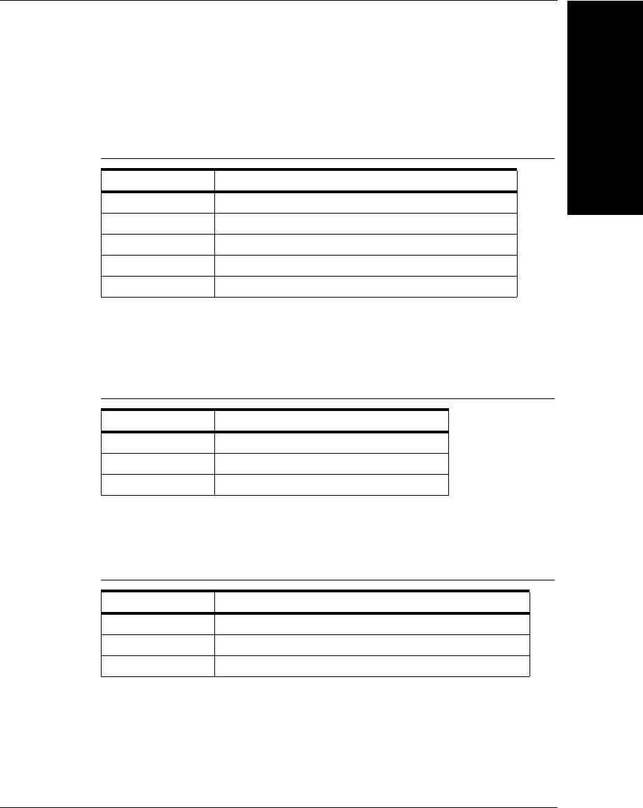
Setup Manager ActiveX Control
Display and Setup
Components
8
Visionscape Programmer’s Kit (VSKit) Manual 8-33
This method returns information about the current state of tryout
option settings. The information is packed into a 32-bit word. The bits
are described in Table 8–16.
In addition, the upper 16 bits of the tryout flags are in turn divided into
two 8-bit byte values. The least significant of these bytes (the low
byte of the high word) is interpreted as described in Table 8–17.
The most significant of these bytes (the high byte of the high word) is
interpreted as described in Table 8–18.
Return Values - Returns tryout information if successful and -1 if not.
• Sub ImageTackCurrent()
TABLE 8–16. GetTryoutFlags — Bit
Bit Description
0 Acquire new image during tryout
1 Loop
2 Use I/O during tryout
3 Delay between tools
4 Wait for Triggers during tryout
TABLE 8–17. GetTryoutFlags -LSB
Value Description
0 Tryout entire application
1 Tryout current inspection only
2 Tryout current snapshot only
TABLE 8–18. GetTryoutFlags -MSB
Value Description
0 Tryout without stopping on intermediate steps
1 Stop the tryout on failed tools
2 Stop the tryout on model tools

Chapter 8Display and Setup Components
8-34 Visionscape Programmer’s Kit (VSKit) Manual
This method tacks the currently displayed buffer. Typically, as you
step through tools in the item list (or during tryout), the buffer
displayed is the output buffer of the selected tool. When the image is
tacked, the buffer is not changed as you select tools in the list or
during tryout.
Return Values - None.
• Sub ImageUntackCurrent()
This method untacks the currently displayed buffer. Typically, as you
step through tools in the item list (or during tryout), the buffer
displayed is the output buffer of the selected tool. This method
restores this behavior when the image is tacked.
Return Values - None.
• Function LiveVideo(bStartLive As Boolean) As Boolean
This method starts and stops live video display. The bLiveStart
parameter can be True to start live video or False to stop it. After live
video has been terminated, all inputs are regenerated, if necessary, in
order to redisplay the buffer currently active in the Buffer Manager
display.
Return Values - Returns True if successful and False if not.
• Function NextItem() As Boolean
This method selects the next item in the list of items to be set up.
Return Values - Returns True if successful and False if not.
• Sub OpenImage(strFileName As String)
Opens the given TIFF image
Return Values - None.
• Sub PixelBufToCtrl(xPixel As Integer, yPixel As Integer)
This method converts given pixel values in the buffer space to the
control's client space. Zooming and scrolling are taken into effect.
Control space is the Setup Manager control, not the embedded Buffer
Manager control.

Setup Manager ActiveX Control
Display and Setup
Components
8
Visionscape Programmer’s Kit (VSKit) Manual 8-35
• Sub PixelCtrlToBuf(xPixel As Integer, yPixel As Integer)
This method converts given pixel values in the control's client space
to buffer space. Zooming and scrolling are taken into effect. Control
space is the Setup Manager control, not the embedded Buffer
Manager control.
• Function PrevItem() As Boolean
This method selects the previous item in the list of items to be setup.
Return Values - Returns True if successful and False if not.
• Sub RefreshDatums()
Force Datum Manager to update it's list of datums and their values for
the current step
• Sub RefreshStepList()
Refresh the Step List
• Sub RefreshView()
This method redraws the buffer without regenerating any tools.
• Sub SaveCurrentImage(strFileName As String)
Saves the currently displayed image to the given TIFF name
• Function ScrollTo(x As Long, y As Long) As Long
Scrolls Buffer Manager image to x,y at top left
• Function SelectInspection(InspectionNumber As Long) As Boolean
This method selects the specified inspection number. This must be a
valid zero-based inspection index within the step program as
specified in the previous Edit() call.
Return Values - Returns True if successful and False if not.
• Function SelectItem(ItemNumber As Long) As Boolean
This method selects the specified item. This must be a valid zero-
based item index within the current list of items to be set up.

Chapter 8Display and Setup Components
8-36 Visionscape Programmer’s Kit (VSKit) Manual
Return Values - Returns True if successful and False if not.
• Function SelectSnapshot(SnapshotNumber As Long) As Boolean
This method selects the specified snapshot number. This must be a
valid snapshot index (zero-based) within the current inspection.
Return Values - Returns True if successful and False if not.
• Function SelectStep(hStep) As Long
This method selects the step specified by the step handle value in the
hStep parameter. This must be a valid step handle within the current
inspection.
Return Values - 0 if successful, non-zero if not.
• Function SetTryoutFlags(TryoutFlags As ETryoutFlags) As Boolean
This method sets the tryout option settings. The information is packed
into a 32-bit word. Refer to “Function GetTryoutFlags() As
Long” on page 8-32 for more information.
Return Values - Returns True if successful and False if not.
• Function SetTryoutIterations(TryoutIterations As Long) As Boolean
This method sets the number of times the step program will be cycled
the next time the TryoutStart() function is called. To run repeatedly,
until the TryoutStop() function is called, use the value zero for
TryoutIterations.
Return Values - Returns True if successful and False if not.
• Function TrainCurrentItem() As Boolean
This method causes a Train operation to be performed on the current
item. This is only applicable for trainable tools.
Return Values - Returns True if successful and False if not.
• Function TrainCurrentShape() As Boolean
This method trains the currently selected shape in the Buffer display.
Return Values - Returns True if successful and False if not.

Setup Manager ActiveX Control
Display and Setup
Components
8
Visionscape Programmer’s Kit (VSKit) Manual 8-37
• Function TrainItem(ItemNumber As Long) As Boolean
This method causes a Train operation to be performed on the
specified item number. This is only applicable for trainable tools.
Return Values - Returns True if successful and False if not.
• Function TrainShape(hStep As Long) As Boolean
This method trains the shape specified by Step handle.
Return Values - Returns True if successful and False if not.

Chapter 8Display and Setup Components
8-38 Visionscape Programmer’s Kit (VSKit) Manual
• Function TryoutContinue() As Boolean
This method causes a previously paused tryout to resume.
Return Values - Returns True if successful and False if not.
• Function TryoutCurrentItem() As Boolean
This method runs the current setup item and any necessary steps to
provide registration information for the current item.
Return Values - Returns True if successful and False if not.
• Function TryoutKillWaitForTrigger() As Boolean
Closes the “Waiting for Trigger” dialog if open and returns True,
returns False if dialog was not open.
• Function TryoutPause() As Boolean
This method pauses a running tryout.
Return Values - Returns True if successful and False if not.
• Function TryoutStart() As Boolean
This method starts a tryout run of the application. The behavior is
determined by the current tryout options.
Return Values - Returns True if successful and False if not.
• Function TryoutStop() As Boolean
This method stops a running tryout. The next time a tryout is started,
it will start at the beginning.
Return Values - Returns True if successful and False if not.
• Function WizardFinish([bForceExit As Boolean = False]) As Boolean
This method exits Wizard Mode. The first item in the setup list is
selected and you can randomly select any tool in the list.
Return Values - Returns True if successful and False if not.
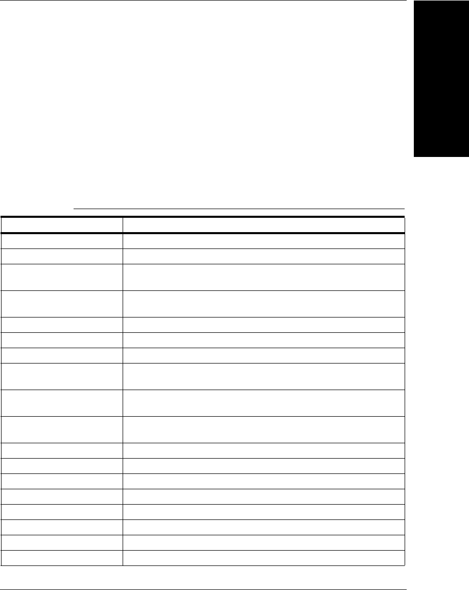
Setup Manager ActiveX Control
Display and Setup
Components
8
Visionscape Programmer’s Kit (VSKit) Manual 8-39
• Function WizardStart() As Boolean
This method starts setup in the Wizard Mode. The first item in the
setup list is selected and you must proceed through each step in
order, until all steps have been trained and set up.
Return Values - Returns True if successful and False if not.
Events
Table 8–19 lists the events of the control.
TABLE 8–19. Setup Manager Events
Name Description
AcquireDone Sent when an image acquisition has been completed.
AcquireStarted Sent when an image acquisition has been started.
DatumGotFocus Sent when a specific datum in the Properties View gets the
keyboard focus.
DatumsChanged Sent when you change the datums of a particular step in the
Properties display. Handle of the step that was changed is given.
ItemOrShapeSelected Sent when an item or a shape has been selected.
ItemSelectedEvent A new item has been selected in the setup item checklist.
LiveModeChanged Sent when Live Video mode is toggled.
MouseDown Standard stock event, but only fired when mouse is clicked in the
image. Coordinates are in SetupMgr control space.
MouseMove Standard stock event, but only fired when mouse is clicked in the
image. Coordinates are in SetupMgr control space.
MouseUp Standard stock event, but only fired when mouse is clicked in the
image. Coordinates are in SetupMgr control space.
ShapeSelectedEvent Sent when a particular shape is selected in the Buffer display.
ToolInserted Sent whenever a new tool has been inserted
ToolMoved Sent if the user moves the ROI of one of the Steps
ToolToBeDeleted Sent when a tool is about to be deleted.
ToolTrained Sent whenever a tool is trained
TryoutFlagsChanged Sent when you change the Tryout flags through the user interface.
TryoutIterationDone Sent when a tryout iteration has completed.
TryoutPauseEvent Tryout mode has been paused.
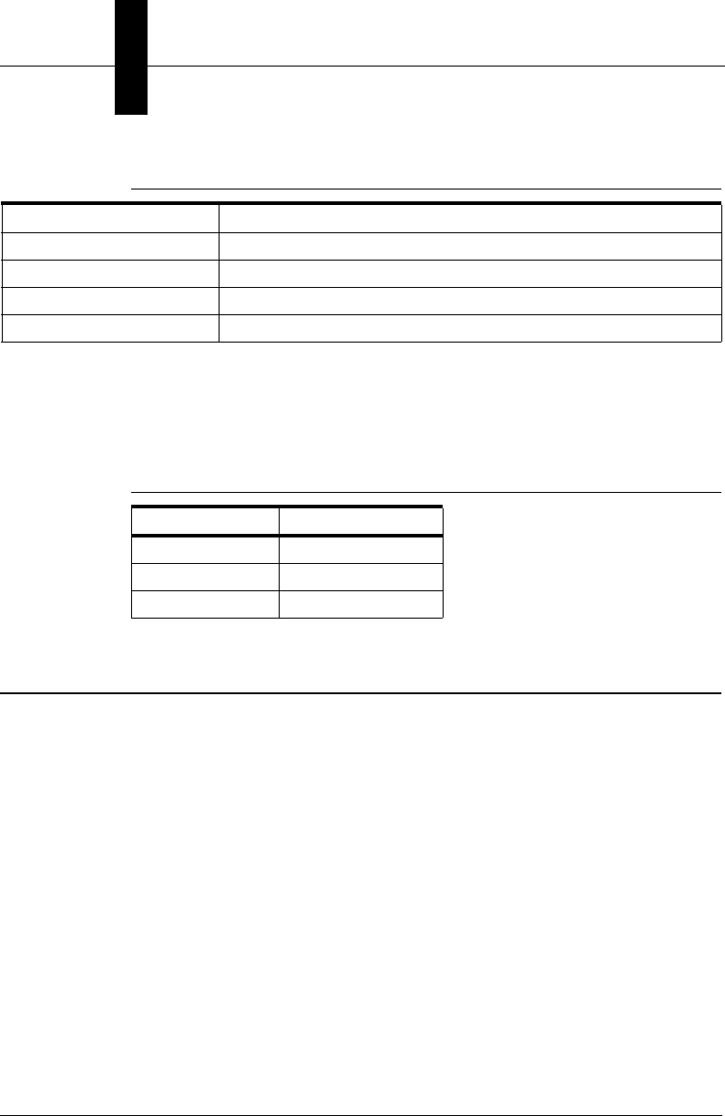
Chapter 8Display and Setup Components
8-40 Visionscape Programmer’s Kit (VSKit) Manual
Error Codes
Table 8–20 lists the error code values. The error codes are low-order
word values.
Job Manager ActiveX Control
The Job Manager ActiveX Control displays a user interface for editing the
steps and datums within a job. To add a Job Manager to your project, you
will need to add the following component.
+Visionscape Controls: Job Manager
Editing does not include training, only step insertion and deletion, as well
as the ability to edit the datums of each step in the job. Figure 8–12
shows an example of Job manager.
TryoutStartEvent Tryout mode has started.
TryoutStopEvent Tryout mode has been stopped.
UpdateItemEvent The state of the current item has changed; update any GUI.
WizardDoneEvent Wizard Mode has finished.
TABLE 8–20. Setup Manager Error Codes
Name Numeric Value
S_OK 0h
E_POINTER 80004003h
E_FAIL 80004005h
TABLE 8–19. Setup Manager Events (continued)
Name Description
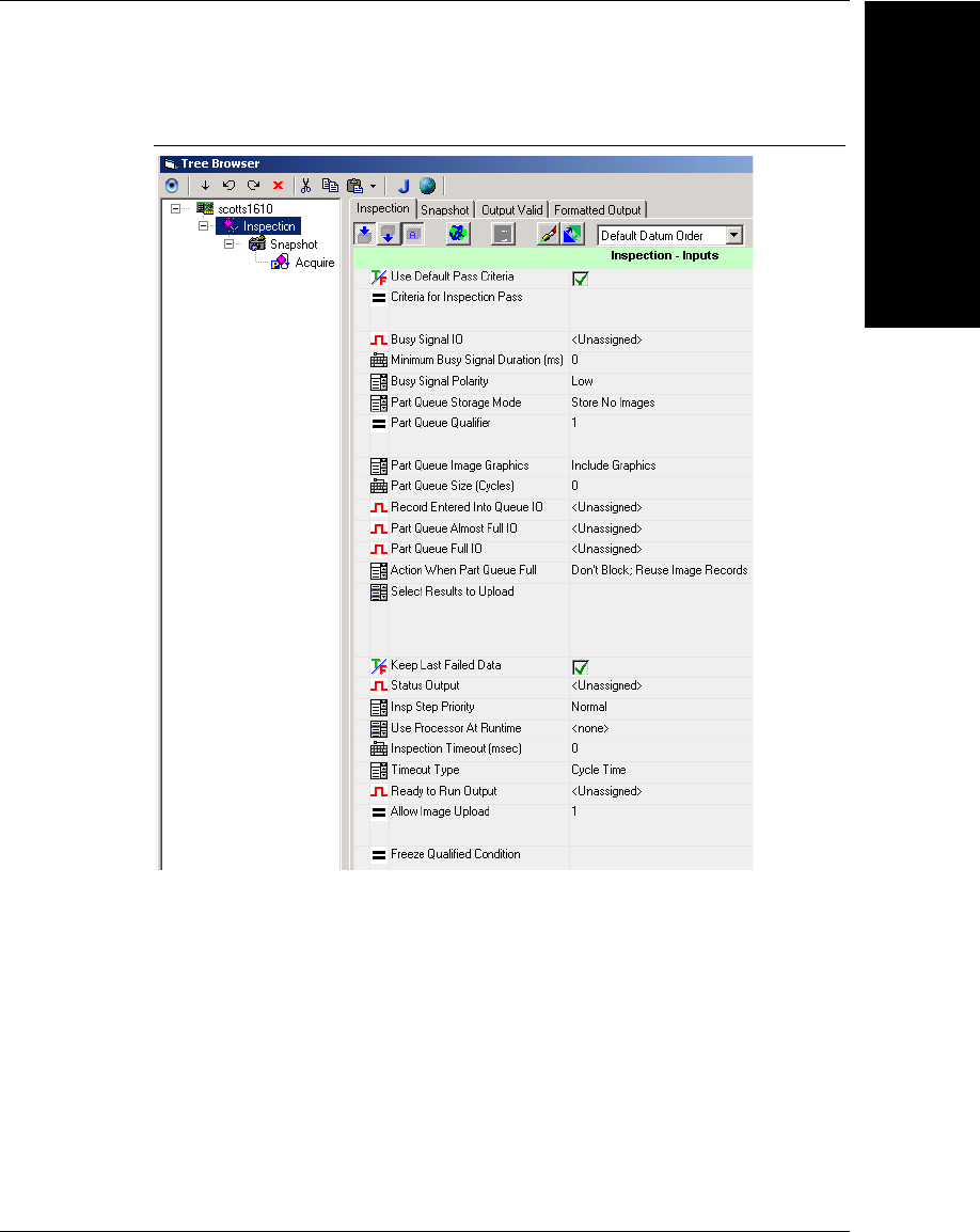
Job Manager ActiveX Control
Display and Setup
Components
8
Visionscape Programmer’s Kit (VSKit) Manual 8-41
FIGURE 8–12. Job Manager User Interface
The Job Manager contains three distinct sections: Job Tree, Toolbar, and
Properties Window.
Job Tree
The left pane in the Job Manager contains the Job Tree. The job tree
displays the steps of a job in its parent/child relationship. That is, a step
may contain several child steps. In the example in Figure 8-27, the
Snapshot step has Acquire, 2PinFind, and WarpRect as its child steps.
The Inspection has Snapshot as its child. When a job is executed, it
executes in the order displayed in the tree.
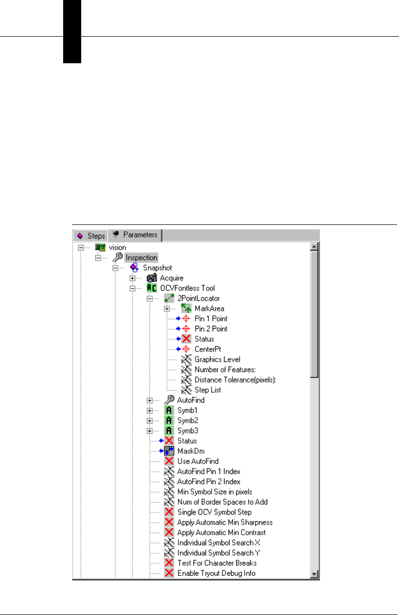
Chapter 8Display and Setup Components
8-42 Visionscape Programmer’s Kit (VSKit) Manual
The Job Tree also has a tab control at the top with two selections, Steps
and Parameters. When Steps is selected, the Job Tree displays all the
steps in the job. When Parameters is selected, the job steps and each
step's parameters are displayed. Figure 8–13 shows an example of a job
containing an OCV Fontless tool. A step contains a set of datums (or
parameters). The tree displays each datum as child of the parent step.
The blue arrow to the left of the datum's image indicates that the datum is
an output datum, the results of which can be updated when the step is
executed.
FIGURE 8–13. Datum Tree Display
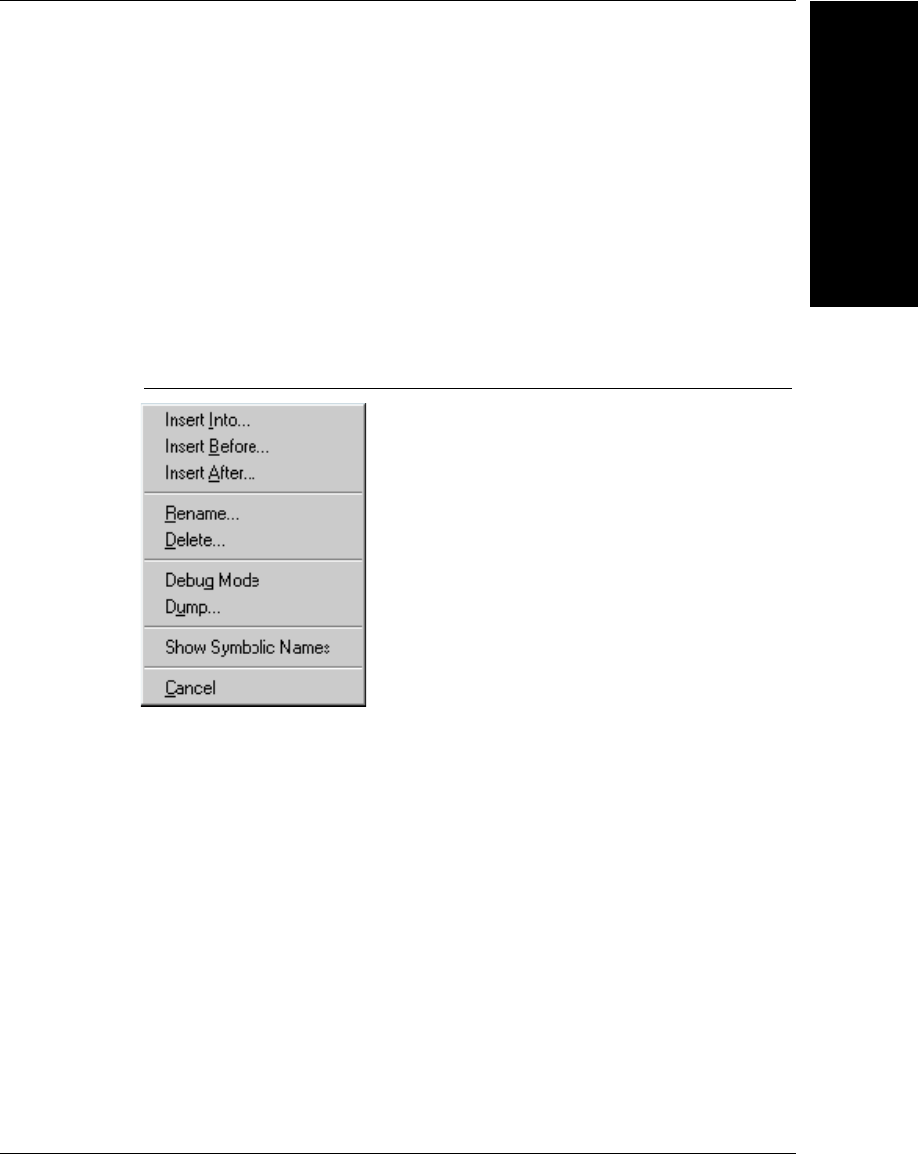
Job Manager ActiveX Control
Display and Setup
Components
8
Visionscape Programmer’s Kit (VSKit) Manual 8-43
Context Menus
The user can right-click the mouse on different portions of the Job Tree
for a context menu of options pertaining to the selected item. These
context menus include Step and Datum.
Step
Right-click a step to display the Step Context Menu, as shown in
Figure 8–14.
FIGURE 8–14. Step Context Menu
The Step Context Menu allows you to:
• Insert Into — Inserts a step into the current step (as a child).
• Insert Before and Insert After — Inserts a step before or after the
current step (as a child of the selected step's parent).
• Rename — Renames the selected step. The step's name in the tree
view becomes a tiny edit control. Also, you can select the step, wait
briefly, and then click it again to rename the step.
• Delete — Deletes the selected step after confirmation.
• Debug Mode — Toggles the debug mode state of the step. This step-
dependent action is a debugging feature, and is disabled in this
version of the software.
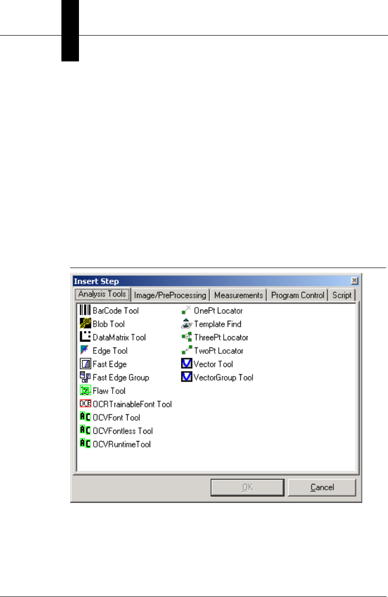
Chapter 8Display and Setup Components
8-44 Visionscape Programmer’s Kit (VSKit) Manual
• Dump — Dumps a textual printout of the step tree to the debug
window in the debugger. This action is a debugging feature, and is
disabled in this version of software.
• Show Symbolic Names — When selected, symbolic names for every
item in the JobTree are displayed along with the User Name. Enable
it to take a screen shot of the tree if necessary.
• Cancel — Cancels a selection.
When inserting a step, the Insert A Step dialog box is displayed, as
shown in Figure 8–15. The contents of this dialog box will vary. The Insert
A Step dialog box displays all the steps pertinent to the selected parent
step.
FIGURE 8–15. Insert Step Dialog Box
Datum
When you right-click on a datum in the Job Tree, the Datum Context
Menu is displayed, as shown in Figure 8–16.
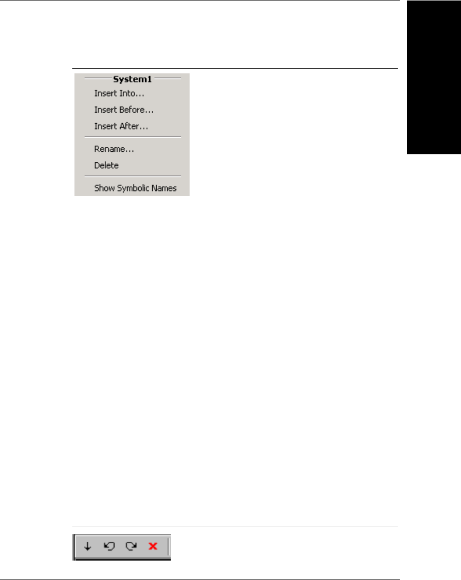
Job Manager ActiveX Control
Display and Setup
Components
8
Visionscape Programmer’s Kit (VSKit) Manual 8-45
FIGURE 8–16. Datum Context Menu
The Datum Context Menu allows you to:
• Insert Into — Inserts a step into the current step
• Insert Before — Inserts a step before the current step (as a child of
the selected step's parent).
• Insert After — Inserts a step after the current step (as a child of the
selected step's parent).
• Rename — Renames the selected datum. The datum's name in the
tree view becomes a tiny edit control. Also, you can select the datum,
wait briefly, and then click it again to rename the datum.
• Delete — Deletes the selected step (after confirmation).
• Show Symbolic Names — When selected, symbolic names for every
item in the JobTree are displayed along with the User Name. Enable
it to take a screen shot of the tree if necessary.
Toolbar
The Toolbar, as shown in Figure 8–17, flanks the top of the control. The
Toolbar buttons display tool tips that describe their actions. These actions
correspond to the same menu items in the Step Context Menu, as
explained in “Step” on page 8-43.
FIGURE 8–17. Job Manager Toolbar

Chapter 8Display and Setup Components
8-46 Visionscape Programmer’s Kit (VSKit) Manual
Edit Parameters Window
The Edit Parameters Window contains a tab selection along the top. The
tab selection displays the selected step, as well as the first-generation
child of the selected step. When you select a step in the Job Tree, the tab
selection updates to the newly selected step, and the lower portion of the
window displays the editable datums for the selected tab. The user can
edit the datums, which are step-dependent. Clicking on another tab or on
another step in the Job Tree causes the current datum values to be
saved.
Using Job Manager in your Application
1. You Must Have a Job Loaded in Memory
You use Job Manager by connecting it to the currently loaded Job. This
means you should be familiar with the concepts covered in Chapter 2,
and understand how to load an AVP file into a JobStep object.
2. Connect Job Manager using the JobStep Property
The JobStep property is used to connect the control to one of the Steps in
your Job. Job Manager can be connected to any Step in your Job, but you
would typically connect it to either your JobStep or VisionSystem step.
This property takes a Step Handle. The following is a simple example that
loads a Job and then connects a Job Manager control (named ctlJob in
this example) to the first VisionSystem step in the Job:
Private m_job As JobStep
Private m_vs As VisionSystemStep
Private m_coord As VsCoordinator
Private m_dev As VsDevice
Private Sub Form_Load()
'instantiate our objects
Set m_coord = New VsCoordinator
Set m_job = New JobStep
'get the first available device
Set m_dev = m_coord.Devices(1)
'load our sample job
m_job.Load "C:\Vscape\Tutorials &
Samples\Sample Jobs\ProgSample_MultiCam.avp"

Job Manager ActiveX Control
Display and Setup
Components
8
Visionscape Programmer’s Kit (VSKit) Manual 8-47
Set m_vs = m_job(1) 'get first VisionSystem step
'connect job to hardware
m_vs.SelectSystem m_dev.Name
'connect our Job Manager to the first VisionSystem
ctlJobMgr.JobStep = m_vs.Handle
End Sub
3. Disconnect Job Manager When Using Other Controls
As with Setup Manager, the Job Manager should be disconnected before
you connect other Visionscape components. Likewise, you should always
disconnect those other Visionscape components before connecting Job
Manager. YOUR APPLICATION MAY CRASH IF YOU DO NOT FOLLOW
THIS RULE. Disconnect Job Manager by setting the JobStep property to
0, like this:
ctlJobMgr.JobStep = 0
The following Visionscape Controls should always be disconnected
before connecting Job Manager, and Job Manager should always be
disconnected before connecting any of them:
• VsRunView
• Runtime Manager
• Setup Manager
4. Always Disconnect Before Deleting Your Job
If Job Manager is connected to your currently loaded Job, and you delete
it, bad things can happen. This generally applies to two scenarios:
• Your deleting the current Job in order to load a new Job.
• Your application is closing down.
In each of these scenarios, your application could crash if you don't
disconnect Job Manager. So, when changing Jobs, always disconnect
Job Manager first. When your application closes down, remember to
disconnect Job Manager in your Form_Unload logic.
5. Job Manager Works With Step Handles
Throughout this manual we have talked about the Step object and how to
use it. You should understand that the Job Manager does not deal with

Chapter 8Display and Setup Components
8-48 Visionscape Programmer’s Kit (VSKit) Manual
the Step object directly, it instead deals with Step handles. Have no fear,
the conversion is quite easy.
• When Passing Step Handle to Job Manager: The Step Object has a
Handle property, so this is quite easy to provide.
• When Job Manager returns a Step Handle to you, what do you do
with it? A Step Handle can be converted to a Step object by using the
AvpHandleConverter object. As an example, you might write code to
respond to Job Manager's StepSelected event. This event is fired
whenever the user selects a different step in the tree, and the handle
of that step is passed into the event handler. The following example
shows you could then convert that handle to a Step Object:
Private Sub ctlJobMgr_StepSelected(ByVal hStep As Long)
Dim hc As New AvpHandleConverter
Dim selStep As Step
If hStep <> 0 Then
'convert the handle to a Step Object
Set selStep = hc.AvpObject(hStep)
Debug.Print "Selected Step = " & selStep.Name
End If
End Sub
Properties
Table 8–21 summarizes the Job Manager control properties.
TABLE 8–21. Job Manager Control Properties
Name Type Description
AutoUpdateEnable Boolean When True, the tree will automatically update
when steps are inserted or deleted
programmatically.
ISelectedStep IStep Step interface to the step currently selected in the
Job Tree.
JobEnableEditing Boolean When True, user can edit the Job. When False,
only the JobTree is displayed and you cannot edit
it.
JobStep HSTEP Handle (longword) to the job loaded into the Job
Manager.

Job Manager ActiveX Control
Display and Setup
Components
8
Visionscape Programmer’s Kit (VSKit) Manual 8-49
Methods
• Sub DoInsertStepDlg(nType As INSERTTYPE)
Launches the insert step dialog, allowing the user to choose a new
step to be inserted into the Job. The new step will be inserted relative
to the currently selected step, and the nType parameter specifies
where the step will be inserted.
– INSTYPE_AFTER — new step is inserted immediately after the
current step.
– INSTYPE_BEFORE — new step is inserted immediately before
the current step.
– INSTYPE_INTO — new step is inserted into the current step, at
the end of the child list.
RootVisible Boolean When True, the root of the tree is visible.
SelectedStep HSTEP Handle to the step currently selected in the Job
Tree.
SplitPercentage Integer Defines the size of the job tree as a percentage of
the main window.
SymNamesDisplay Boolean When True, symbolic names are displayed in the
job tree.
TreeTabsVisible Boolean When True, the tabs at the top of the tree are
visible.
ToolbarVisible Boolean When True, the insertion toolbar is visible.
TABLE 8–21. Job Manager Control Properties (continued)
Name Type Description
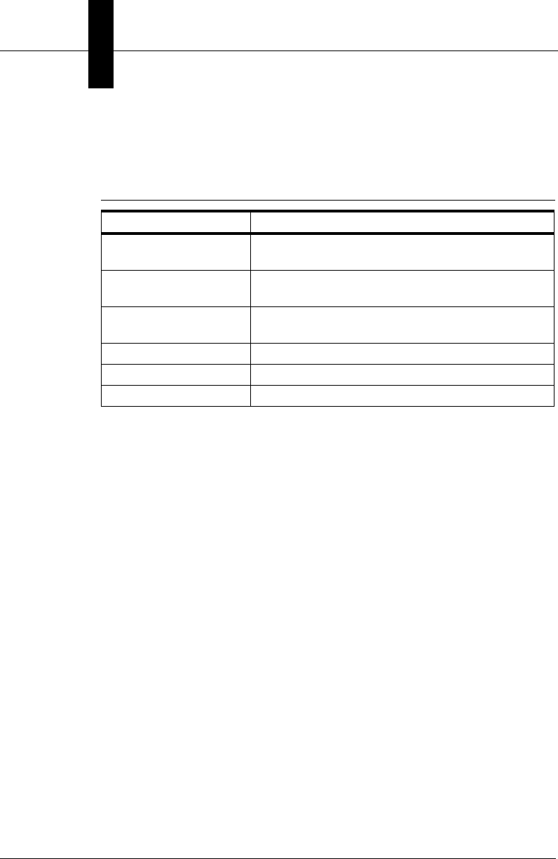
Chapter 8Display and Setup Components
8-50 Visionscape Programmer’s Kit (VSKit) Manual
Events
Table 8–22 lists and details the events of the Job Manager.
• Event CompNameChanged(pComp As Long)
This event is sent when you change the name of a step or datum in
the job tree. The pComp parameter is the handle to the Composite
whose name has changed.
• Event DatumGotFocus(hStep As Long, strDatum As String)
This event is sent when a specific datum in the Properties View gets
the keyboard focus. The handle of the owner step and the symbolic
name of the datum are sent.
• Event DatumsUpdated(pStep As Long)
This event is sent when you edit in the Edit Parameters Window. The
pStep parameter is the step whose datums have been updated.
• Event StepDeleted(pFromParent As Long)
This event is sent when a step is deleted from the job. The
pFromParent parameter is the step handle to the parent step whose
child was just deleted.
TABLE 8–22. Job Manager Events
Name Description
CompNameChanged Sent when you change a Composite name in the
Job Tree.
DatumGotFocus Sent when a datum in the Properties View gets the
keyboard focus.
DatumsUpdated Sent when you click Apply in the Edit Datums
Window.
StepDeleted Sent when a step is deleted from the job.
StepInserted Sent when a step is inserted into the job.
StepSelected Sent when a step is selected in the tree.

Datum Grid Active X Control
Display and Setup
Components
8
Visionscape Programmer’s Kit (VSKit) Manual 8-51
• Event StepInserted(pStep As Long, pParent As Long)
This event is sent when a step is inserted into the job. The pStep
parameter is the handle to the step just inserted and the pParent
parameter is the handle of its parent step.
• Event StepSelected(hStep As Long)
This event is sent when a new step is selected in the job tree. The
hStep parameter is the handle to the step just selected.
Error Codes
Table 8–23 lists the error code values.
Datum Grid Active X Control
The Datum Grid control is used to display all of the datums for a given
step, both input and output datums. If the Enable property is set to True,
then the Datum Grid will allow the user to modify the values of any input
datums. To use the Datum Grid control, add the following Component to
your project:
DatumGridLib
Figure 8-36 shows a Datum Grid control displaying the datums of a Blob
Tool:
TABLE 8–23. Job Manager Error Codes
Name Numeric Value
S_OK 0h
E_FAIL 80004005h
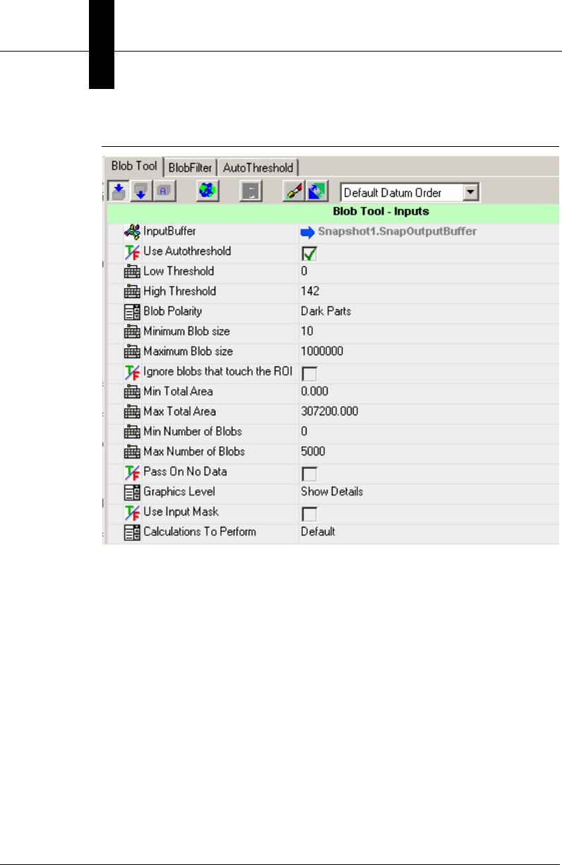
Chapter 8Display and Setup Components
8-52 Visionscape Programmer’s Kit (VSKit) Manual
FIGURE 8–18. Datum Grid
Using the Datum Grid in Your Application
The Datum Grid works with Step Objects, so no need to worry about Step
Handles with this control. To use the Datum Grid, you simply connect it to
the Step whose datums you want to display/edit. Connect the Datum Grid
by calling it's ShowDatumsForStep method. In the following brief
example, we search for a Blob Step under the VisionSystem step name
m_vs, and then display it's datums in a Datum Grid control named
ctlDatumGrid:
Dim blob As Step
Set blob = m_vs.Find("Step.Blob", FIND_BY_TYPE
ctlDatumGrid.ShowDatumsForStep blob
You disconnect the DatumGrid by passing Nothing to the
ShowDatumsForStep method, like this:

Datum Grid Active X Control
Display and Setup
Components
8
Visionscape Programmer’s Kit (VSKit) Manual 8-53
ctlDatumGrid.ShowDatumsForStep Nothing
You should disconnect your DatumGrid controls whenever the form on
which they live is closed.
Properties
Table 8–24 summarizes the control properties of the DatumGrid control.
TABLE 8–24. Datum Grid Properties
Name Type Description
AutoRegenerate Boolean When True, tells the DatumGrid that the
AutoRegenerate feature is active in your
app. If you have also set the
RunStepOnDatumChange property to
True, then the DatumGrid will
automatically PreRun and then Run the
selected step whenever the user modifies
a datum value. Set to False to disable this
behavior.
Enabled Boolean When True, the user is allowed to modify
the input datum values. Set to False if you
wish to disable editing and use the
DatumGrid to view the current values only
PrecisionPix Integer Specifies the number of decimal places to
be used when displaying floating point
values in pixel units
PrecisionWorld Integer Specifies the number of decimal places to
be used when displaying floating point
values in world units
RunStepOnDatumCh
ange
Boolean If this property is set to True, and the
AutoRegenerate property is also True,
then the DatumGrid will PreRun and Run
the selected Step whenever a datum value
is changed. Set to False to disable this
functionality.
SortOption enumDatumGridSortOpt Allows you to specify how the datums
should be sorted in the grid
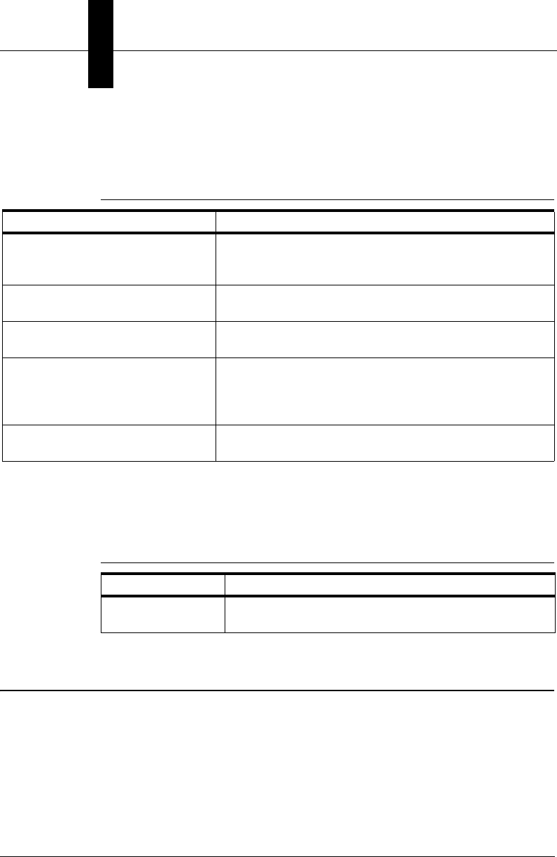
Chapter 8Display and Setup Components
8-54 Visionscape Programmer’s Kit (VSKit) Manual
Methods
Table 8–25 summarizes the Datum Grid's Methods.
Events
Table 8–26 summarizes the Datum Grid’s events.
StepTreeView ActiveX Control
StepTreeView is a Visual Basic based ActiveX control that provides a
simple mechanism for displaying Step trees. This is the control used by
Job Manager to display the Job Tree. The StepTreeView allows you to
display Step icons or execution status icons, and provides options for
highlighting trainable steps, filtering Setup, Resource, and PreProc steps
in the tree, and allows you to optionally edit the names of the Steps in the
TABLE 8–25. Datum Grid Methods
Name Description
Clear Clears the DatumGrid's internal list of datums. The
appearance of the DatumGrid will not change, however,
unless you call the Show method.
ClosePropertyPage Closes the Custom Property Page if it has been opened
for the current step.
Refresh Tells the DatumGrid to refresh it's contents for the
currently selected Step.
Show Tells the DatumGrid to re-display it's internal list of
datums. It does not re-read the datum list of the currently
selected Step. Call Refresh if you want the current Step's
data to be re-read.
ShowDatumsForStep(s as Step) Displays the Input and Output Datums of the Step object
specified in the s parameter.
TABLE 8–26. Datum Grid Events
Name Description
DatumChanged Fired whenever the user modifies a datum value. A
reference to the modified datum is passed into the event.
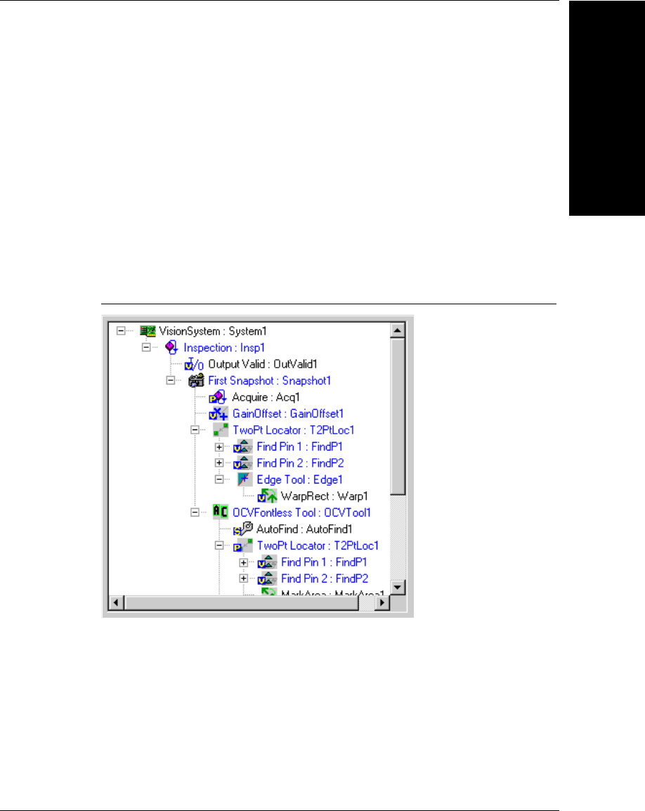
StepTreeView ActiveX Control
Display and Setup
Components
8
Visionscape Programmer’s Kit (VSKit) Manual 8-55
tree. Add the following component to your project in order to access the
StepTreeView control.
+Visionscape Controls: StepTreeView
StepTreeView is not used to edit the tree itself, use Job Manager for that.
It’s used only for advanced Step tree display.
Theory Of Operations
This control is a UI based control that provides a Tree display, as shown
in Figure 8–19.
FIGURE 8–19. StepTreeView Control
The developer can drop this control onto a form and set its RootStep
property to any step in the tree in order to view the Step tree from that
entry point. The developer can also select options to display the trainable
steps, use custom highlighting and filtering, and control what category of
steps are displayed in the tree. Nodes in the tree and events about nodes
in the tree are always referenced through the related IStep or IComposite
interface for the node.

Chapter 8Display and Setup Components
8-56 Visionscape Programmer’s Kit (VSKit) Manual
Properties
Table 8–27 lists all the available properties of this control in alphabetical
order.
TABLE 8–27. Control Properties
Name Type Description
AllowMultiSelect Bool When True, you can select multiple
entries in the tree.
AllowNameChange Bool When True, you can edit the Step names
in the Tree. The default is True.
AllowNavigation Bool When True, you can navigate the tree
(open, close nodes). The default is True.
AutoUpdateEnable Bool When True, addition or deletion of Steps
is automatically detected and reflected in
the tree.
Enabled Bool When True, object responds to events.
Font Font* Returns/sets the Font to use in this
control.
HighlightColor OLE_COLOR Color to use when highlighting steps or
datums.
HighlightTrainSteps Bool When True, Trainable steps are
displayed with a bold font. The default is
True.
IconState Custom Enum type When ICON_STEPTYPE, icons
displayed in the tree represent the Step
types. When ICON_NONE, no icons are
displayed in the tree. The default is
ICON_STEPTYPE.
Indent Short Value used for branch indentation in the
tree.
RootStep IStep* Step handle to the root Step used for
display.
SelectedComposite IComposite* Returns/sets the currently selected
Composite.
SelectedComposites IAvpCollection* Returns/sets the set of selected
Composites in the tree when you can
select multiple Composites.

StepTreeView ActiveX Control
Display and Setup
Components
8
Visionscape Programmer’s Kit (VSKit) Manual 8-57
SelectedStep IStep* Returns/sets the currently selected Step.
ShowDatums Bool When True, Datums are displayed in the
tree.
ShowHidden Bool When True, Steps marked as “hidden”
are shown in the tree anyway. The
default is False.
ShowPart Bool When True, Part Steps are shown in the
tree. The default is True.
ShowPreProc Bool When True, Preprocessing Steps are
shown in the tree. The default is True.
ShowPrivate Bool When True, Private Steps are shown in
the tree.
ShowResource Bool When True, Resource Steps are shown
in the tree. The default is True.
ShowSetup Bool When True, Setup Steps are shown in
the tree. The default is True.
ShowSymNames Bool When True, symbolic and user Step
names are shown in the tree. The default
is True.
UseCustomAdd Bool When True, the owner can validate
whether or not a node is added to the
tree. The owner must implement the
ISTVCustomHighlight interface.
UseCustomHighlight Bool When True, the owner can implement
the ISTVCustomHighlight interface and
provide custom highlighting of steps or
datums.
TABLE 8–27. Control Properties (continued)
Name Type Description
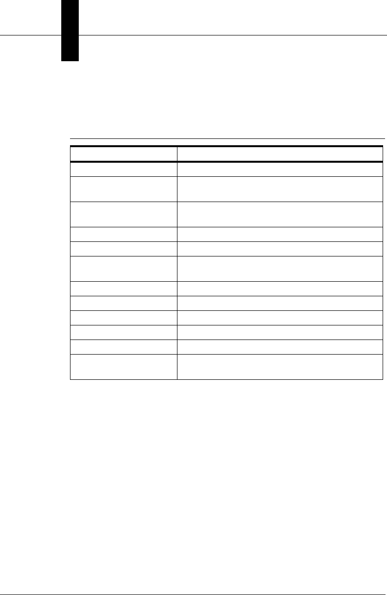
Chapter 8Display and Setup Components
8-58 Visionscape Programmer’s Kit (VSKit) Manual
Node Management Methods
Table 8–28 lists all methods associated with Node Management.
• Sub NodeClose(stepObj As Step)
This method closes the node in the tree specified by stepObj.
Error Codes: E_INVALIDARG if the step is invalid.
• Sub NodeDelete(stepObj As Step)
This method removes the node in the tree specified by stepObj. This
method doesn't delete the Step, it just deletes the tree node.
Error Codes: E_INVALIDARG if the step is invalid.
TABLE 8–28. Node Management Methods
Name Description
NodeClose Closes a particular node in the tree
NodeDelete Deletes a node from the tree (doesn't delete the
Step, just deletes the tree node)
NodeHitTest Returns the Composite underneath the given X,Y
position
NodeIsOpen Returns True if a node in the tree is open
NodeOpen Opens a particular node in the tree
NodeRefresh Refreshes a node in the tree (e.g., a Step is
retrained)
NodesCollapseAll Collapses all the nodes in the tree
NodesExpandAll Expands all the nodes in the tree
NodeTextColorGet Returns the text color of the given node
NodeTextColorSet Set the text color of the given node
Refresh Forces a complete repaint of a form or control
StartNameChange Starts the name change UI process in the tree for
the selected node

StepTreeView ActiveX Control
Display and Setup
Components
8
Visionscape Programmer’s Kit (VSKit) Manual 8-59
• Function NodeHitTest(x As Single, y As Single) As Composite
This method returns a reference to the Step or Datum (as a
Composite) in the tree that is under the given mouse position, or
returns Nothing.
• Function NodeIsOpen(stepObj As Step) As Boolean
This method returns True if the node represented by stepObj is
“open”.
Error Codes: E_INVALIDARG if the step is invalid.
• Sub NodeOpen(stepObj As Step)
This method opens the node specified by stepObj.
Error Codes: E_INVALIDARG if the step is invalid.
• Sub NodeRefresh(stepObj As Step, stateOnly As Boolean)
This method refreshes the node specified by stepObj. This method is
used whenever a Step in the tree needs refreshing (e.g., when a Step
is retrained). If statesOnly is set to True, then only the execution state
of the given Step is refreshed.
Error Codes: E_INVALIDARG if the step is invalid.
• Sub NodesCollapseAll()
This method collapses all nodes in the tree to the root.
• Sub NodesExpandAll()
This method expands all nodes in the tree.
• Function NodeTextColorGet(comp As Composite) As OLE_COLOR
This method returns the text color for the node specified by comp.
• Sub NodeTextColorSet(comp As Composite, color As OLE_COLOR)
This method sets the text color to color for the node specified by
comp.
• Sub Refresh()

Chapter 8Display and Setup Components
8-60 Visionscape Programmer’s Kit (VSKit) Manual
This method completely repaints the control.
• Sub StartNameChange()
This method starts the name change process in the control for the
selected composite.
Events
Table 8–29 lists all the events of the control.
Error Codes
This section lists all of the custom error code values. Standard error code
values can be retrieved in Visual Basic using the API Text Viewer.
TABLE 8–29. Events
Name Description
Click Stock event
CompositeNameChanged Sent when you have changed the name of a
Composite in the tree
DblClick Stock event
KeyDown Stock event
KeyUp Stock event
MouseDown Stock event
MouseMove Stock event
MouseUp Stock event
NameChangeBegin Sent when you are about to begin editing a
name in the tree
NameChangeEnd Sent when you have ended the edit of a name
in the tree.
NodeClosed Sent when a tree node is closed
NodeOpened Sent when a tree node is opened
NodeSelected Sent when a node is selected in the tree
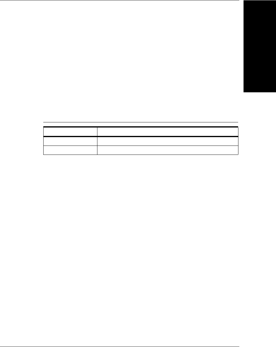
StepTreeView ActiveX Control
Display and Setup
Components
8
Visionscape Programmer’s Kit (VSKit) Manual 8-61
ISTVCustomHighlight Interface
This interface is used by the control when the owner wants to either
customize the highlighting of nodes in the tree or when the owner wants
to customize the addition of nodes in the tree. The owner can implement
the interface in Visual Basic by adding the keywords “Implements
ISTVCustomHighlight” and implementing the methods.
Methods
Table 8–30 lists the methods of the control.
• Sub ConfirmAdd(obj As Composite, bAdd As Boolean)
To add this object as a node in the tree, the owner must set bAdd to
True. The owner will be called whenever nodes are added to the tree.
Error Codes: E_INVALIDARG if the step is invalid.
• Sub ConfirmHighlight(obj As Composite, bHighlight As Boolean)
To highlight this object in the tree, the owner must set bHighlight to
True. The owner will be called whenever nodes are added to the tree.
TABLE 8–30. Methods
Name Description
ConfirmAdd Confirms the addition of a node to the tree.
ConfirmHighlight Confirms the highlighting of a node in the tree.

Chapter 8Display and Setup Components
8-62 Visionscape Programmer’s Kit (VSKit) Manual

Visionscape Programmer’s Kit (VSKit) Manual A-1
A
Examples
A
APPENDIX A Examples
Additional samples can be found in:
C:\Vscape\Tutorials & Samples\VsKit Samples
Example 1 — Load and Run
Loading, Connecting Hardware and Running
In this Visual Basic 6 example, we will walk you step by step through the
process of building a very simple yet powerful user interface. In this
example we will load an AVP file from disk, connect it to the first available
device in your system, start it running, and then view all of its images and
results using the VsRunView control. This example is appropriate for any
Visionscape GigE Camera, but is not the best approach for smart
cameras. Refer to the Monitor example for the best approach to use with
smart cameras. To get started, create a new project in Visual Basic 6, and
choose “Standard EXE” for the project type.
Add References and Components to Your Project
Go to your Project menu, select References, and add the following:
+Visionscape Library: Device Objects
Go to your Project menu, select Components, and add the following:
Appendix AExamples
A-2 Visionscape Programmer’s Kit (VSKit) Manual
+Visionscape Controls: VsRunKit
Name Your Project and Form
Change the name of your Project to LoadAndRun. Change the name of
your form to frmMain.
Drop the VsRunView Control on Your Main Form
In the Visual Basic Toolbox window, you should see the following icon,
which represents the VsRunView control:
Select this icon in the Toolbox, and then click and drag on your main form
in order to add a VsRunView control to it. It should look something like
this:

Example 1 — Load and Run
Examples
A
Visionscape Programmer’s Kit (VSKit) Manual A-3
FIGURE A–1. VsRunView Control Added
Change the name of the control to “ctlRunView”.

Appendix AExamples
A-4 Visionscape Programmer’s Kit (VSKit) Manual
Add Global Variables to frmMain
At the top of the frmMain code window, declare the following variables:
Private m_coord As VsCoordinator
Private m_dev As VsDevice
Add Code to the Form_Load Event
In frmMain's Form_Load event, you will need to do the following:
1. Select the Device your Job will be running on. This is done by getting
a VsDevice reference from the VsCoordinator object. If you have
multiple devices, you can search for the one you want by name. In
this case, we're going to assume that you want to run on the first
device available
2. Download your AVP to the Device. By calling the DownloadAVP
method of VsDevice, we can open our chosen AVP file, connect it to
the device and have it ready to run with one line of code.
3. Connect the VsRunView control by calling its AttachDevice method
4. Start the inspections running by calling the StartInspection method of
VsDevice. Add the following code to accomplish these tasks:
Private Sub Form_Load()
'create an instance of the VsCoordinator object
Set m_coord = New VsCoordinator
'get a reference to the first device
Set m_dev = m_coord.Devices(1)
'download the sample AVP to this device
m_dev.DownloadAVP _
"C:\Vscape\Tutorials &
Samples\Sample Jobs\ProgSample_MultiCam.avp", 0
'Attach the VsRunView control
ctlRunView.AttachDevice m_dev
'tell control to open a view for every snapshot
ctlRunView.OpenAllSnaps
'starts all inspections by default
m_dev.StartInspection

Example 1 — Load and Run
Examples
A
Visionscape Programmer’s Kit (VSKit) Manual A-5
End Sub
Stop Inspections in the Form_Unload Event
When running on host based devices (0740 or 0800), you must stop the
inspections before exiting your application. You may crash if you do not.
So, add the following line of code to your form's Form_Unload event to
stop all inspections from running when your application exits:
Private Sub Form_Unload(Cancel As Integer)
'stops all inspections by default
m_dev.StopInspection
End Sub
Compile and Run
When your application runs, you should see something like this:
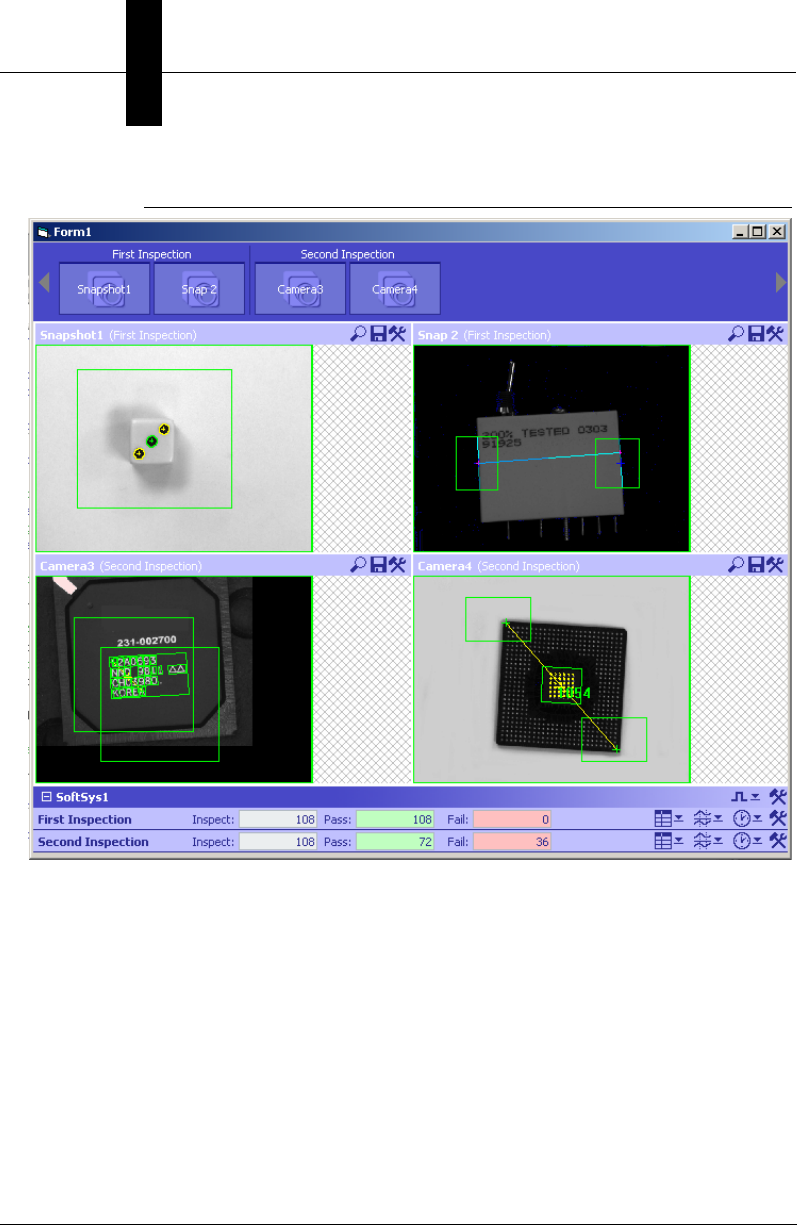
Appendix AExamples
A-6 Visionscape Programmer’s Kit (VSKit) Manual
FIGURE A–2. What You See After Compile and Run
Extras
The following are some other features you might add to this application.
Hide VsRunView Components
In our example, the SnapButtons and the Report Views are both active
and visible. You may prefer to hide the SnapButtons, and prevent the
user from turning the various snapshot views on and off. You can do so
with the following line of code:
ctlRunView.ShowSnapButtons = False

Example 1 — Load and Run
Examples
A
Visionscape Programmer’s Kit (VSKit) Manual A-7
You might also decide that you would prefer to use the VsRunView
control only to show the images, and that you would prefer to handle and
display the uploaded results yourself. In that case, do the following:
1. Hide the Report view area with the following line of code:
ctlRunView.ShowDeviceViews = False
2. Tell the VsRunView control that you want it to pass the reports on to
your application.
ctlRunView.ReportEventEnabled = True
3. Handle the VsRunView's OnNewReport event, and process the
AvpInspReport object in whatever way you need.
Private Sub ctlRunView_OnNewReport(nInspIndex As Integer, rptObj As
AVPREPORTLib.IAvpInspReport, InspNameNode As VSOBJLib.IVsNameNode)
'Stats object holds inspection status, counts and timing
Debug.Print rptObj.Stats.Passed
Debug.Print rptObj.Stats.CycleCount
Debug.Print rptObj.Stats.PassedCount
Debug.Print rptObj.Stats.FailedCount
Debug.Print rptObj.Stats.ProcessTime
'Results collection holds the uploaded results
Dim res As AvpInspDataRecord
For Each res In rptObj.Results
'data is in value property
Debug.Print res.ValueAsString
'name, type and error code are also available
Debug.Print res.Name
Debug.Print res.Type
Debug.Print res.Error
Next
End Sub

Appendix AExamples
A-8 Visionscape Programmer’s Kit (VSKit) Manual
Example 2 — Monitor a Smart Camera
Discover, Connect to, and Monitor a Running Smart
Camera
In this Visual Basic 6 example we will walk you step by step through the
process of building a simple monitoring user interface. The intention of
this application will be to connect to a specific smart camera that is
already running, and begin displaying its images and results. Typically, a
“Monitor” style user interface does not download a Job to the device when
it starts, as in our previous example, its intention is only to monitor what is
currently going on with the device. To get started, create a new project in
Visual Basic 6, and choose “Standard EXE” for the project type.
Add References and Components to your project
Go to your Project menu, select References, and add the following:
+Visionscape Library: Device Objects
Go to your Project menu, select Components, and add the following:
+Visionscape Controls: VsRunKit
Name Your Project and Form
Change the name of your Project to Monitor, and change the name of
your form to frmMain.
Drop the VsRunView Control on Your Main Form
In the Visual Basic Toolbox window, you should see the following icon,
which represents the VsRunView control:
Select this icon in the Toolbox, and then click and drag on your main form
in order to add a VsRunView control to it. It should look something like
this:
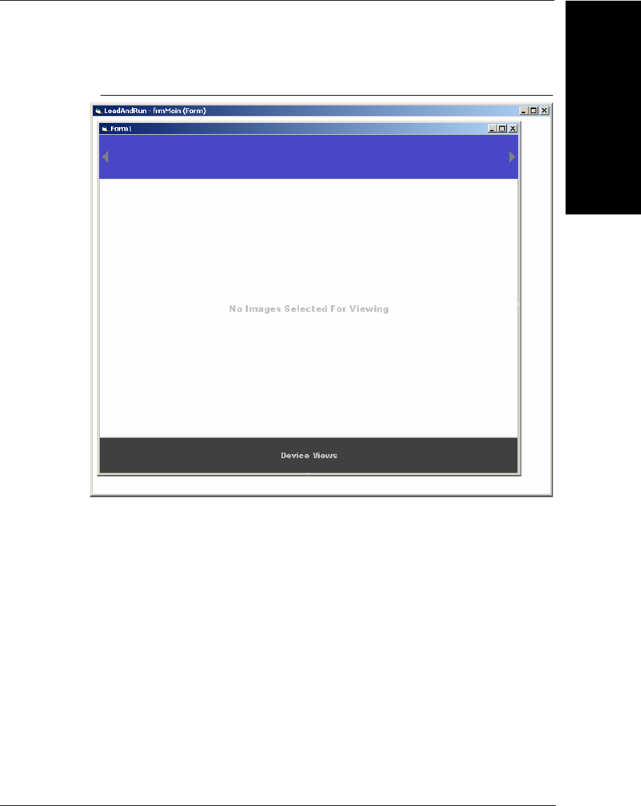
Example 2 — Monitor a Smart Camera
Examples
A
Visionscape Programmer’s Kit (VSKit) Manual A-9
FIGURE A–3. VsRunView Control Added
Change the name of the control to “ctlRunView”.
Add Global Variables to frmMain
At the top of the frmMain code window, declare the following variables:
Private WithEvents m_coord As VsCoordinator
Notice that this time we've added the WithEvents keyword. This is
required because we'll need to respond to the VsCoordinator's
OnDeviceFocus event.

Appendix AExamples
A-10 Visionscape Programmer’s Kit (VSKit) Manual
Add Code to the Form_Load Event
In frmMain's Form_Load event, you will need to do the following:
1. Instantiate the VsCoordinator, and then tell it to notify us when our
device is discovered by passing the device name to the
DeviceFocusSetOnDiscovery method.
2. Hide the Snapshot Buttons in our VsRunView control:
Private Sub Form_Load()
Set m_coord = New VsCoordinator
'call DeviceFocusSetOnDiscovery, passing in the name
' of the Smart Camera. This will cause the
' OnDeviceFocus event to be fired as soon as
' the Smart Camera is discovered on the network
m_coord.DeviceFocusSetOnDiscovery "MyHawkEye_1600T"
'hide snapshot buttons on our VsRunView control
ctlRunView.ShowSnapButtons = False
End Sub
Attach VsRunView in the OnDeviceFocus Event
After calling the DeviceFocusSetOnDiscovery method of VsCoordinator, it
will begin waiting for your specified device to be discovered on the
network. It may be discovered immediately, or it may take between 5 to 10
seconds (Refer to “Networked Device Discovery and UDPInfo” on
page 3-3 for more info on how networked devices are discovered). When
it’s discovered, the OnDeviceFocus event will be fired. This is the signal
to you that it’s safe to attach your VsRunView control to the device, so
that's just what we'll do. We'll also tell the control to open a snapshot view
for all snapshots in the Job, and then we'll update the caption of our main
form.
Private Sub m_coord_OnDeviceFocus(ByVal objDevice As
VSOBJLib.IVsDevice)
'attach VsRunView control to the device
ctlRunView.AttachDevice objDevice
'open the snap views
ctlRunView.OpenAllSnaps
'update our form's caption
Me.Caption = "Monitoring the Device " & objDevice.Name
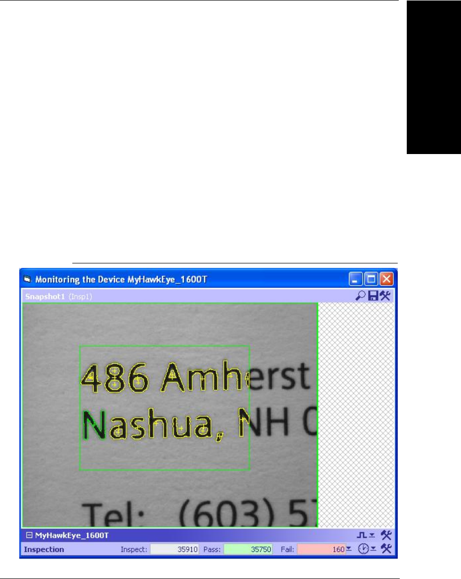
Example 2 — Monitor a Smart Camera
Examples
A
Visionscape Programmer’s Kit (VSKit) Manual A-11
End Sub
Size the VsRunView Control in Form_Resize
Lets size the VsRunView control to fill the entire form. The best place to
do this is in the Form_Resize event:
Private Sub Form_Resize()
'size VsRunView to fill the form
ctlRunView.Move 0, 0, Me.ScaleWidth, Me.ScaleHeight
End Sub
Compile and Run
When your application runs, you should see something like this:
FIGURE A–4. What You See After Compile and Run

Appendix AExamples
A-12 Visionscape Programmer’s Kit (VSKit) Manual
Extras
The following are some other features you might add to this application.
Handle the Uploaded Results Yourself
In our example, the Report Views are active and visible. You may prefer
to use the VsRunView control only to show the images, and you may wish
to handle and display the uploaded results yourself. In that case, do the
following:
1. Hide the Report view area with the following line of code:
ctlRunView.ShowDeviceViews = False
2. Tell the VsRunView control that you want it to pass the reports on to
your application.
ctlRunView.ReportEventEnabled = True
3. Handle the VsRunView's OnNewReport event, and process the
AvpInspReport object in order to extract the results and display them
on your form in whatever way you prefer.
Private Sub ctlRunView_OnNewReport(nInspIndex As Integer, rptObj As
AVPREPORTLib.IAvpInspReport, InspNameNode As VSOBJLib.IVsNameNode)
'Stats object holds inspection status, counts and timing
Debug.Print rptObj.Stats.Passed
Debug.Print rptObj.Stats.CycleCount
Debug.Print rptObj.Stats.PassedCount
Debug.Print rptObj.Stats.FailedCount
Debug.Print rptObj.Stats.ProcessTime
'Results collection holds the uploaded results
Dim res As AvpInspDataRecord
For Each res In rptObj.Results
'data is in the various value propertys
Debug.Print res.ValueAsString
'name, type and error code are also available
Debug.Print res.Name
Debug.Print res.Type
Debug.Print res.Error
Next
End Sub

Example 2 — Monitor a Smart Camera
Examples
A
Visionscape Programmer’s Kit (VSKit) Manual A-13
Monitor Multiple Smart Cameras
Perhaps you have 2 or more smart cameras that you will need to monitor
with your application. It’s very easy to modify this sample application to do
just that. In fact, it only takes one more line of code for each smart camera
you want to add. In the Form_Load event, simply add another call to the
DeviceFocusSetOnDiscover event for each additional smart camera you
want to monitor. So, if you wanted to also monitor a second smart camera
named “MyOtherSmartCamera”, simply add the following to Form_Load:
m_coord.DeviceFocusSetOnDiscovery "MyOtherSmartCamera"
This will cause a second OnDeviceFocus event to be generated when
“MyOtherSmartCamera” is discovered. In the OnDeviceFocus event
handler, we are simply calling the AttachDevice method of the
VsRunView control, and since it’s capable of attaching to multiple
devices, no code needs to be changed there (you may want to change
the code that sets the caption of the form though, since this will only list
the name of the last camera to be discovered). To monitor a third smart
camera, simply add a third call to the DeviceFocusSetOnDiscovery
method, it's that easy.
Add IO Capabilities
Your application may need to monitor the state of certain IO points, or you
may wish to turn certain IO points ON or OFF depending on inspection
results. This can be easily done by implementing the AvpIOClient object.
Refer to “The AVP I/O Library ActiveX Control” on page 7-1 for a
complete description of AvpIOClient, and how to implement it.

Appendix AExamples
A-14 Visionscape Programmer’s Kit (VSKit) Manual

Visionscape Programmer’s Kit (VSKit) Manual B-1
B
Legacy Controls
B
APPENDIX B Legacy Controls
The various components presented in this appendix will allow you to
easily provide users with the ability to adjust tool parameters and ROI
positions (Setup Manager), acquire single images or live video (Setup
Manager again), view or edit the Job tree (Job Manager), or provide more
specialized capabilities. We also present our primary Image display
component, the Buffer Manager control, which can be used to display any
kind of image buffer from any Step or Report Connection. Buffer Manager
can be used along with a Report Connection to display runtime images, or
it can be used to display a Step's output buffer at Setup time. The
following are the ActiveX Controls we will cover in this appendix:
• “Calibration Manager ActiveX Control” on page B-1
• “Datum Manager ActiveX Control” on page B-11
• “Message Scroll Window ActiveX Control” on page B-14
• “Runtime Manager ActiveX Control” on page B-18
Calibration Manager ActiveX Control
The Calibration Manager ActiveX Control provides the necessary APIs
and user interface to perform two-dimensional bilinear calibration, as well
as other APIs to query what can be calibrated. This is the standard
calibration technique used on many Visionscape systems, assuming a
pin-hole model for the camera optical system. As such, the calibration can
map linear distortions, including perspective, for example, when the

Appendix BLegacy Controls
B-2 Visionscape Programmer’s Kit (VSKit) Manual
camera optical axis is not normal to the object plane. Add the following
Component to your project in order to access the Calibration Manager:
+Visionscape Controls: Calibration Manager
Calibration is the process of mapping pixel coordinates to world
coordinates once the position of a visible target in the camera's Field of
View is known. A step program always saves the calibration tree. It
organizes all cameras in the system in a hierarchical fashion, referred to
as the World Part Tree. The World Part Tree is completely abstracted
from the caller of the control. Instead, the caller uses the JobStep handle
and existing Snapshot handles to identify camera views to be calibrated.
The Calibration ActiveX manages all aspects of calibration. Through this
control, a Visual Basic application may calibrate snapshots in step trees,
and may load and save this information to and from calibration files.
Calibration files can be loaded into an existing step program, thereby
updating its bi-linear transforms. Calibration files may contain one or more
camera calibration matrices.
This control provides all persistence for the calibration data. At any time,
calibration data can be extracted from the tree for an entire set of
TargetSteps or for a specific Snapshot and subsequently saved in a
binary file. The caller can then use the Calibration Manager to read this
data back into the tree after loading a set of Targets from disk.
When using the Calibration Manager, Visual Basic programmers must
add the control as a Reference in the project, and then create the
Calibration object at runtime:
Private ctlCal as Calibration
…
Private Sub Form1_Load()
Set ctlCal = new Calibration
ctlCal.JobStep = ctlProg.JobStep
ctlCal.Calibrate( <snapshot step handle> )
End Sub
Visual C++ users can use the #import directive to import the type-library
information into the sources, and then use COM smart pointers to create
CoCalibration objects and ICalibration interfaces:
#import "calibmgr.ocx"
…
ICalibrationPtr pctlCal(__uuidof(Calibration));

Calibration Manager ActiveX Control
Legacy Controls
B
Visionscape Programmer’s Kit (VSKit) Manual B-3
pctlCal->put_JobStep( <job step handle> );
HRESULT hErr = pctlCal->Calibrate(hSnap);
The Calibration Manager ActiveX Control provides a Windows wizard
user interface to walk you through the camera calibrating process. This
Windows wizard user interface allows you to key in the position of the
known target dots in world coordinates. The calibration target contains
eight dots in known locations. The shape and size of these dots is such
that the orientation of the target in the Field of View (FOV) can be inferred
from the relative dot positions. This wizard consists of these three GUIs:
• Dot-entry — Figure B–1, “Calibration Parameters #1,” on page B-4
• Vision — Figure B–2, “Run Calibration Blob Tool,” on page B-5
• Results — Figure B–3, “Robust Calibration Results,” on page B-6
Calibration Windows Wizard Dialog Boxes
The Robust Calibration dialog box (Figure B–1) provides fields to enter
the calibration dot world coordinates and other parameters, such as
Calibration Target Height, Camera Height, and the view direction.
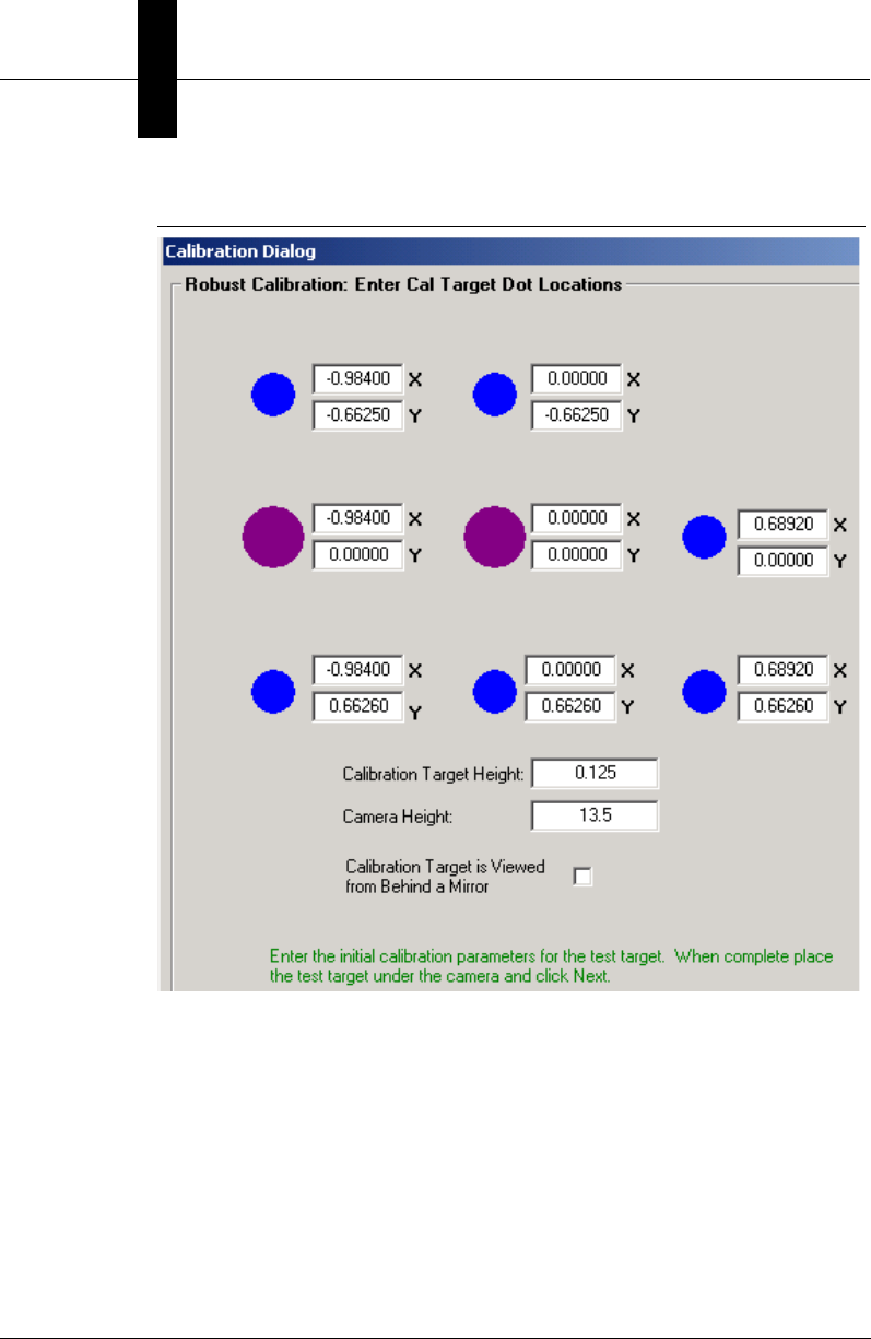
Appendix BLegacy Controls
B-4 Visionscape Programmer’s Kit (VSKit) Manual
FIGURE B–1. Calibration Parameters #1
Click Next> to progress to the Run Calibration Blob Tool dialog box, as
shown in Figure B–2.
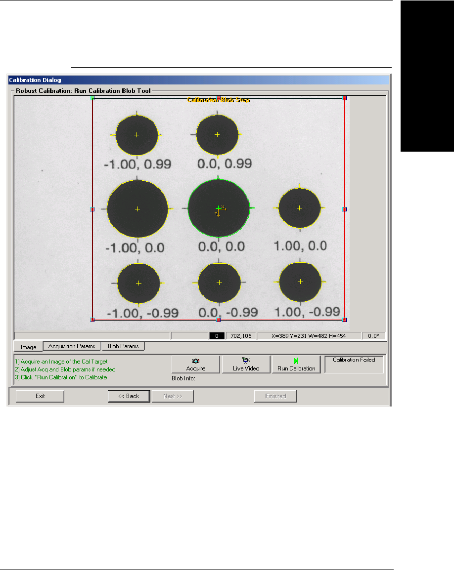
Calibration Manager ActiveX Control
Legacy Controls
B
Visionscape Programmer’s Kit (VSKit) Manual B-5
FIGURE B–2. Run Calibration Blob Tool
This provides a calibration window for you to view the image, adjust the
parameters created during the calibration job, and execute calibration.
• Image — Click to view the image.
• Acquisition Params — Click to adjust acquisition parameters.
• Blob Params — Click to adjust blob parameters.
• Acquire — Click to acquire an image.
• Live Video — Click for Live Video.
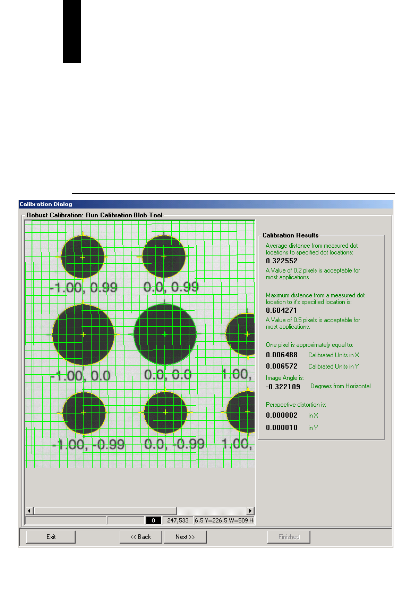
Appendix BLegacy Controls
B-6 Visionscape Programmer’s Kit (VSKit) Manual
• Run Calibrate — Click to execute the calibration.
Notice that a text field provides feedback on the status of the calibration.
Click Next> to progress to the Robust Calibration Results dialog box, as
shown in Figure B–3. This provides detailed results on the quality of the
calibration.
FIGURE B–3. Robust Calibration Results
These results include mean and maximum residuals. Once calibration is
complete, a grid-like pattern is drawn in the image to provide a graphical

Calibration Manager ActiveX Control
Legacy Controls
B
Visionscape Programmer’s Kit (VSKit) Manual B-7
feedback on the position and orientation of the camera plane with respect
to world units.
Properties
Table B–1 summarizes the control properties of the Calibration Manager.
TABLE B–1. Calibration Manager Control Properties
Name Type Description
JobStep HSTEP Handle to the program's root
JobStep. This handle is created
using the Program Manager.
Views StepCollection (read-only) Returns a StepCollection, which
contains a collection of all
Snapshots in the job, e.g., across all
TargetSteps.
ViewsForCamera StepCollection (read-only) Returns a StepCollection containing
a collection of all Snapshots tied to
a specific hardware camera.
Camera is determined by a passed-
in Snapshot handle or by camera
index. Camera index is a zero-
based index of all possible
hardware cameras across all
TargetSteps.

Appendix BLegacy Controls
B-8 Visionscape Programmer’s Kit (VSKit) Manual
Methods
Table B–2 lists and this section describes the methods of the Calibration
Manager. The calibration wizard need not be visible in order to call these
methods.
• void C2D_Cal(VARIANT pixelDots, VARIANT realDots, VARIANT*
world2Pixel, VARIANT* pixel2World, VARIANT* maxResid, VARIANT*
meanResid, VARIANT* maxIndex);
This method computes calibration results:
– pixelDots — (n,3) variant array that contains an ordered set of x
location, y location pixel values, extended by 1 (e.g., x,y,1).
TABLE B–2. Calibration Manager Methods
Name Description
C2D_Cal Computes a calibration matrix as an arithmetic operation.
No vision is performed.
C2D_Calibrate Calibrates a given snapshot programmatically, given a
pixel dot matrix and a real dot matrix. Calibration Results
Datum is returned.
C2D_CamAngle Calculates Camera Angle based on pixel-to-world matrix.
C2D_PixUnit Calculates pixels-per-unit and units-per-pixel given a
pixel-to-world matrix.
C2D_Sort8Dots Sorts the calibration dots into the order expected by
C2D_Cal. The first dot is the large center dot; the second
is the large dot to the right; and the pattern continues
clockwise from there.
Calibrate Calibrates a specified Snapshot and optionally copies the
calibration data to all Snapshots tied to the same
hardware camera.
CalibrationCopy Copies the calibration data from one Snapshot to another.
LoadCalibData Loads calibration data from disk. The caller can load
calibration either to a specific Snapshot or for all
Snapshots in the Job.
SaveCalibData Saves calibration data to disk. The caller can either save
all Snapshots in the Job or a specific Snapshot.

Calibration Manager ActiveX Control
Legacy Controls
B
Visionscape Programmer’s Kit (VSKit) Manual B-9
– realDots — (n,3) variant array that contains an ordered set of the
x and y world locations corresponding to pixel dots, extended by
1 (e.g., x,y,1).
– world2Pixel — Forward calibration matrix.
– pixel2World — Backward calibration matrix.
– maxResid — Maximum residuals.
– meanResid — Mean residuals.
– maxIndex — Dot index with the worst residual.
• ICalResultDm* C2D_Calibrate(ISnapshotStep* snapObj, VARIANT
pixelDots, VARIANT realDots, long sortTheDots);
This method calibrates the given SnapshotStep object
programmatically. The pixelDots and realDots variables are the Nx3
pixel dot locations and real-world dot locations to use for calibration
calculations. The results of the calibration are stored in the
CalResultDm object within the given snapObj. An interface to this
object is then returned to the caller. Calibration results can be probed
through this ICalResultDm interface. You can also choose whether or
not to sort the dot locations when using the 8x3 calibration matrix.
• void C2D_CamAngle(VARIANT p2wMatrix, double* camAngle);
This method calculates the camera angle given the Nx2 pixel-to-world
dot locations. The matrix must be a two-dimensional array of x, y
positions.
• void C2D_PixUnit(VARIANT p2wMatrix, double* p2wX, double* p2wY,
double* w2pX, double* w2pY);
This method calculates the pixel-to-world and world-to-pixel units
based on a pixel-to-world matrix. The matrix is the pixel-to-world dot
location calibration matrix with dimensions Nx2.
• void C2D_Sort8Dots(VARIANT pixelDots, VARIANT flip, VARIANT*
sortedDots);
This method sorts the calibration dots into the order expected by
C2D_Cal:

Appendix BLegacy Controls
B-10 Visionscape Programmer’s Kit (VSKit) Manual
– pixelDots — (8,3) variant array containing the x location, y
location, and area (all in pixels) of the 8 calibration dots on the
target in some arbitrary order.
– Flip — Input boolean that identifies how the calibration target is
viewed, either from the front (False) or the back (True). This
parameter is used for situations where a calibration target is
being viewed by two cameras from both sides.
– sortedDots — (8, 3) variant array that contains the sorted dots.
The first sorted dot is the large center dot; the second is the large
dot adjacent to the first, and the pattern continues in a clockwise
(FLIP = False) or counter-clockwise (FLIP = True) order from
there.
• void Calibrate(long hSnap, long index, EnumPostCalibrate calCopy);
This method performs a calibration on a specific camera view and
optionally copies all results to each view on the same camera. The
view is passed in as either hSnap, a handle to the Snapshot, or by
View index. The View index is the index of the Snapshot from the
Views property (StepCollection). This method invokes the calibration
wizard that allows you to set up and perform a calibration. See
“Calibration Windows Wizard Dialog Boxes” on page B-3.
• void CalibrationCopy(long viewFrom, long viewTo);
This method copies calibration settings from one view (Snapshot) to
another.
• void LoadCalibData(HSTEP hSnap, BSTR bstrName);
This method loads the calibration from the given file to the given
hSnap view (Snapshot). Pass 0 to hSnap to load all views in JobStep
from the same file. The maximum number of Snapshots are loaded
from the file when the number of Snapshots in the job does not
exactly match the number of calibration sets stored in the file.
• void SaveCalibData(HSTEP hSnap, BSTR bstrName);
This method saves the calibration data for hSnap (Snapshot handle)
to the given file. Pass 0 to hSnap to save all views for JobStep in the
same file.
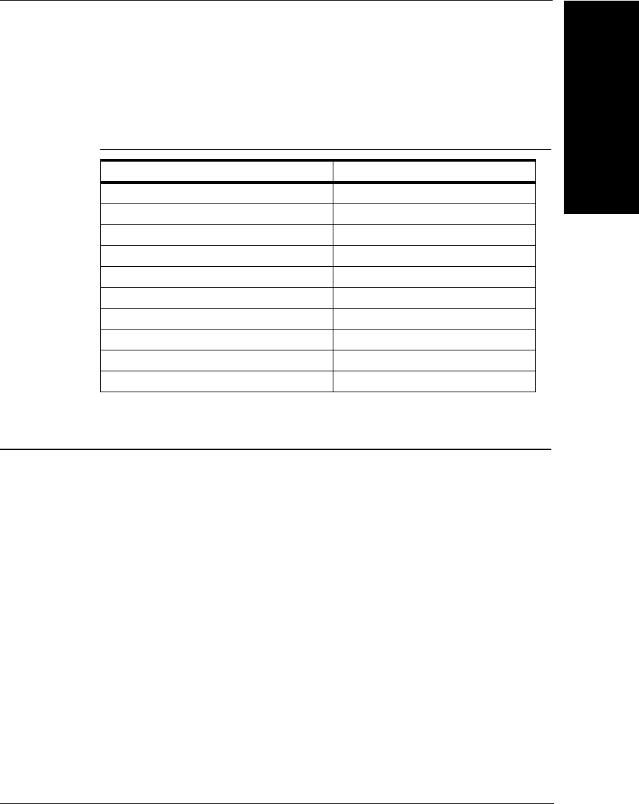
Datum Manager ActiveX Control
Legacy Controls
B
Visionscape Programmer’s Kit (VSKit) Manual B-11
Error Codes
Table B–3 lists the error code values.
Datum Manager ActiveX Control
The Datum Manager ActiveX Control provides a properties display
window of the datums for a given step. Steps can contain input, resource,
and output datums. This control allows users to edit the datums of a
particular step, along with its child steps. Add the following Component to
your project to access Datum Manager:
+Visionscape Controls: Datum Manager
Figure B–4 shows an example of the Datum Manager.
TABLE B–3. Calibration Manager Error Codes
Name Numeric Value
S_OK 0h
E_FAIL 4005h
E_INVALIDARG 57h
CALIBMGR_E_NOJOB 900h
CALIBMGR_E_NOFILENAME 901h
CALIBMGR_E_BADCAMERAINDEX 902h
CALIBMGR_E_BADVIEWINDEX 903h
CALIBMGR_E_BADSTEPHANDLE 904h
CALIBMGR_E_FILEACCESS 905h
E_UNEXPECTED FFFFh
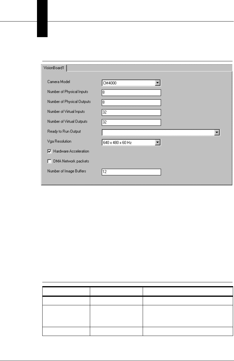
Appendix BLegacy Controls
B-12 Visionscape Programmer’s Kit (VSKit) Manual
FIGURE B–4. Datum Manager Example
The top of the window is a tab-selection control that displays the current
step and all its visible substeps. The middle of the window is a scrolling
view that contains all the editable datums for the selected step in the tab-
selection. The user can change the datum values in the window and, by
default, the values are automatically saved in the step after a quiet-time of
½ second. The control container can change the auto-apply and auto-
apply wait times.
Properties
Table B–4 lists the control properties of the Datum Manager.
TABLE B–4. Datum Manager Control Properties
Name Type Description
hStep long (HSTEP) Parent step in the control.
AutoRegenerate Boolean When True, the current tool is
regenerated whenever parameters
are changed.
UserMode long Not implemented
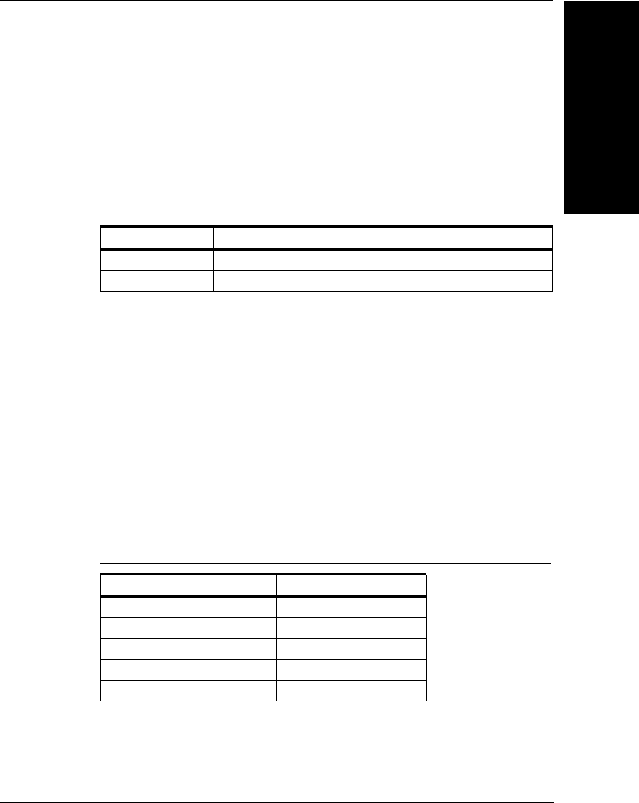
Datum Manager ActiveX Control
Legacy Controls
B
Visionscape Programmer’s Kit (VSKit) Manual B-13
Methods
There are no methods for this control.
Events
Table B–5 lists and this section details the Datum Manager event.
• void DatumGotFocus(long hStep, BSTR strDatum);
This event is sent when a datum gets the keyboard focus. The handle
of the Parent Step is sent along with the symbolic name of the datum.
• void OnApply(HSTEP hStep);
This event is sent when you cause the data of the step to be
changed. The handle to the changed Step given is hStep.
Error Codes
Table B–6 lists the error code values. The error codes are low-order word
values.
TABLE B–5. Datum Manager Event
Name Description
DatumGotFocus Sent when a particular datum gets the keyboard focus.
OnApply Sent when changes are applied.
TABLE B–6. Datum Manager Error Codes
Name Numeric Value
S_OK 0h
E_FAIL 80004005h
E_UNEXPECTED 8000FFFFh
DATUMMGR_E_NOSTEP 80040400h
E_INVALIDARG 80070057h

Appendix BLegacy Controls
B-14 Visionscape Programmer’s Kit (VSKit) Manual
Message Scroll Window ActiveX Control
The Message Scroll Window ActiveX Control displays text messages in a
scrollable window. The owner of the control sets the maximum number of
messages, the background color, and the individual color of each
message as it’s added to the display. The owner can also activate logging
on the control to save every message to a text file. Add the following
component to your project to access the Message Scroll Window.
+Visionscape Controls: Message Window
The control also uses the Registry to hook existing DLLs in memory.
When hooked, the DLLs use a callback mechanism to place messages
into the window. Hooked DLLs must already be loaded in memory; this
control does not perform that function. For example, when FrontRunner
creates the control, it hooks the existing Perl Step library for any
messages that need to be printed on the host during inspection Tryout.
Compilation/parsing errors in Perl are also printed to the control.
Use the Message Scroll Window control in debugging situations when
users want debugging text messages dumped into it. Color-coding can be
used to visually group messages together.
The control can contain a finite number of messages through which you
can scroll. When the last message is visible in the control's window, the
control is autoscrolled to the bottom when new messages are added to
the window. Otherwise, the control assumes you are viewing older
messages in the control and simply adds the messages to its internal list.
When the maximum number of messages is reached, the control
removes the oldest message in the list.
Properties
Table B–7 lists the control properties of the Message Scroll Window
Active X.

Message Scroll Window ActiveX Control
Legacy Controls
B
Visionscape Programmer’s Kit (VSKit) Manual B-15
Methods
Table B–8 lists, and this section describes, the methods of the Message
Scroll Window.
TABLE B–7. Message Scroll Window Control Properties
Name Type Description
AllowExternalMessageHooks Boolean When True, external DLLs (such as
PERLSTEP.DLL) can hook the DLL
to print messages into it.
BackColor Stock Background color of the control.
Font Stock Font used by the control to draw
messages.
LogAppend Boolean When logging is activated, this value
dictates what to do with the old
logging file. When True, the new
messages are appended to the file.
When False, the old file is thrown out.
LogFilePath String Full file path to the logging file that
logs messages to disk. The default is
the empty string.
LogOn Boolean Set to True at runtime to activate
logging for new messages.
MsgMax Short Maximum number of messages in the
control. The default is 999. The owner
can change this value at runtime. If
the number of messages is greater
than the new value, the oldest
messages in the window are thrown
out.
Appendix BLegacy Controls
B-16 Visionscape Programmer’s Kit (VSKit) Manual
• void LogClear();
This method clears the LogFilePath string.
• void MsgAdd(BSTR strText, long rgbColor);
This method adds a text message to the window. Text messages are
single line strings and can contain tabs. The RGB color value used for
drawing the message is rgbColor. The color value has the hex format
of 0x00BBGGRR to define the intensity of each color from 0 to 255.
When no rgbColor value is given, 0 (black) is used as the default.
• void MsgClearAll();
This method clears all messages in the window.
Events
Table B–9 lists the events for this control.
Hooking DLLs for Internal Messages
The Message Scroll Window Manager hooks DLLs listed in the Registry
for messages. The control reads all the subkeys under:
TABLE B–8. Message Scroll Window Methods
Name Description
LogClear Clears the LogFilePath property.
MsgAdd Adds a new message to the window in the given color.
MsgClearAll Clears all messages in the window, but does not touch the
log file.
TABLE B–9. Message Scroll Window Events
Name Description
OnAddedImportantMsg Sent when an external process or thread adds an
important message to the window. The owner can
then decide whether or not to show the window.

Message Scroll Window ActiveX Control
Legacy Controls
B
Visionscape Programmer’s Kit (VSKit) Manual B-17
\\HLKM\SOFTWARE\Visionscape\AIMsgWnd\MsgHooks
Each subkey contains the name of a DLL to hook for messages. The DLL
must be previously loaded in memory when the control is instantiated.
The DLL to be hooked must contain the following entry point:
typedef void (*PFN_AIMSGCALLBACK)(char* pszMsg, long rgbColor);
static PFN_AIMSGCALLBACK _pfnMsg; // static var to use for sending msgs
__declspec(dllexport) void AISetMsgHook(PFN_AIMSGCALLBACK pfnCallback)
{
/* if pfnCallback is not NULL, we are hooking, save ptr away
if pfnCallback is NULL, we are unhooking */
_pfnMsg = pfnCallback;
/* before using the callback, need to check it for NULL */
}
The control calls this entry point with the pointer to a function to use for a
message callback. When the DLL needs to print a message to the control,
it calls the callback function with the formatted string and color, similar to
the MsgAdd API. The control does not discern anything about the call.
The hooked DLL determines when to add messages to the window.
The hooked DLL is also responsible for validating the callback function
pointer before calling. When the control is instantiated, the hooked DLLs
are called with a valid callback function. When the control is destroyed,
the same entry point is called with a NULL pointer to clear the callbacks.
The control uses critical sections to synchronize access to the internal
message list to prevent a hooked DLL from sending messages while it’s
being unhooked.
Error Codes
Table B–10 lists the error code value. The error codes are low-order word
values. The control only sends the E_FAIL error code, but always
includes a description of the error when it occurs.
TABLE B–10. Message Scroll Window Manager Error Code
Name Numeric Value
E_FAIL 80004005h

Appendix BLegacy Controls
B-18 Visionscape Programmer’s Kit (VSKit) Manual
Runtime Manager ActiveX Control
If you are a veteran of Visionscape programming, then you are familiar
with the Runtime Manager control. Runtime Manager has historically
been the primary control that programmers used to display images, and
receive uploaded results from running jobs. With the introduction of the
VsRunView control, we feel we have presented users with a more
powerful and easy to use control than the Runtime Manager. However,
there is nothing wrong with continuing to use this control. If you are
bringing old applications forward to Visionscape V3.7, and don't wish to
convert your code, you don't have to. If you have always used the
Runtime Manager and feel comfortable with it, you may continue to use it
with confidence.
Note: There is one issue with Runtime Manager that you should be aware
of. Runtime Manager is an ActiveX control that was created using the
Microsoft Foundation Classes (MFC). There is a problem with MFC that
causes a small memory leak whenever you destroy an instance of
Runtime Manager. Because the problem lies within MFC, this is not a
problem we can address. In a typical user interface where the main form
contains a Runtime Manager, and this form stays alive for the entire life of
your application, this leak will not cause you a problem. But if you have a
scenario where a Runtime Manager lives on a separate form, and this
form will be loaded and unloaded again and again over time, then you
may eventually leak enough memory to drag down your system
performance, and eventually crash. If you choose to use the Runtime
Manager in your application, avoid situations where you will be
instantiating and destroying this control over and over again.
Converting Runtime Manager Applications to New
Components
If you are familiar with using the Runtime Manager in your UIs, but you
would like to upgrade your application to the latest components, you may

Runtime/Target Manager ActiveX Control
Legacy Controls
B
Visionscape Programmer’s Kit (VSKit) Manual B-19
become a bit confused as to which components replaced which areas of
key Runtime Manager functionality. Table B–11 should help:
The standard Runtime Manager documentation follows.
Runtime/Target Manager ActiveX Control
The Runtime Manager works in conjunction with the Target Manager.
This section provides control properties, methods, events, and error
codes applicable to either or both Runtime and Target Manager ActiveX
Controls.
The Runtime Manager ActiveX Control control can be used to control
Visionscape devices at runtime. Callers use the Runtime Manager to
download jobs, start/stop inspections, upload results, and display runtime
images. To include the Runtime Manager in your project, add the
following to your list of Components:
+Visionscape Controls: Runtime Manager
The Target Manager ActiveX Control supports the Runtime Manager, but
has no user interface. It’s used for target communications with the host
PC, communicating with the target vision device using remote procedure
calls over TCP/IP. The Target Manager downloads jobs, starts/stops jobs,
TABLE B–11. Runtime Manager Functionality Conversion Table
Runtime Manager Functionality Component
Runtime Image Display VsRunView (Chapter 4)
or
VsFilmStrip (Chapter 5)
or
A Report Connection and a Buffer Manager control
(Chapter 6)
Downloading Jobs VsDevice Download and DownloadAVP methods
(Chapter 3)
Handling Uploaded Inspection Results VsRunView (Chapter 4)
or
Report Connections (Chapter 6)
Inspection Control, Starting/Stopping VsDevice.StartInspection VsDevice.StopInspection
IO AvpIOClient (Chapter 8)
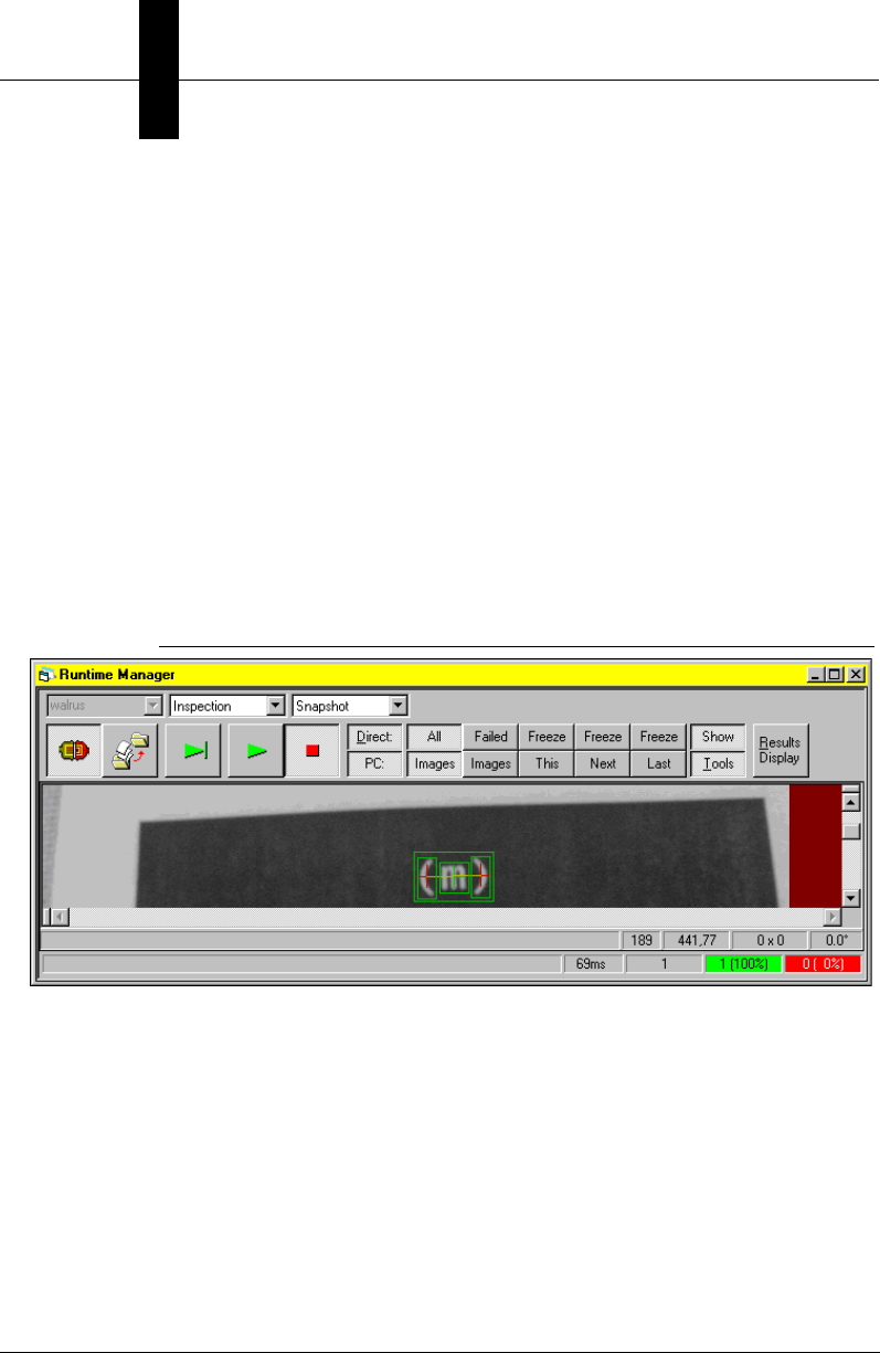
Appendix BLegacy Controls
B-20 Visionscape Programmer’s Kit (VSKit) Manual
changes the target and remote video display options, and uploads datum
results from the target.
When deciding which control to use, your applications should use the
Runtime Manager, which encapsulates all the functionality of the Target
Manager and also provides a TargetMgr property for direct access to its
embedded Target Manager control. On the host PC, all Runtime
Managers connected to the same target are synchronized to each other
using its control's window handle. This synchronization signals each
Runtime Manager when a job is downloaded, stopped, started, etc. When
you use a Target Manager control as a reference, you are circumventing
this synchronization and may introduce issues in your code. Always use a
Runtime Manager control and keep it hidden (RunMgr.Visible = False) if
you do not want your users to access its user interface. Figure B–5
displays an example of the Runtime Manager.
FIGURE B–5. Runtime Manager Example
The Runtime Manager contains Toolbar buttons for you to control various
functions. The center portion of the window is a Buffer Manager ActiveX
Control, which displays the Live Image from the target system. This
control has its own Buffer Manager display information. Refer to “Buffer
Manager ActiveX Control” on page 8-2 for more information. The bottom
of the window is a Status Bar, which contains informational text and an
overall statistics display.
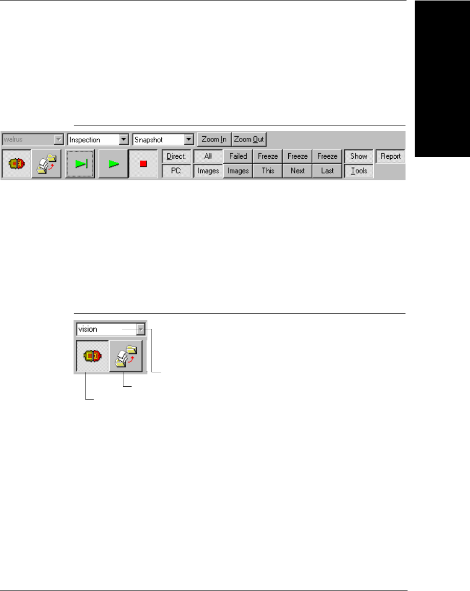
Runtime/Target Manager ActiveX Control
Legacy Controls
B
Visionscape Programmer’s Kit (VSKit) Manual B-21
Toolbar
The Toolbar (Figure B–6) is the main user interface for the Runtime
Manager.
FIGURE B–6. Runtime Manager Toolbar
The Toolbar contains buttons to select and connect to a vision system,
download a job, select inspections and snapshots, start/stop jobs, and
provide image display and results display control.
Connection Control
The Connection Controls (Figure B–7) control the connection to the target
system.
FIGURE B–7. Connection Control
The Network Name drop-down list displays the local Vision Systems in
the host PC. The user can select any system, or type in the appropriate
system name, if it’s remote. The lower buttons control the system
connection. The Connect/Disconnect button toggles the connection state.
When depressed, the host PC and target system connect using TCP/IP.
The Download Job button allows you to select a file using the standard
Open File dialog box, and then perform a Download Job to the target
system. Any job that previously existed on the target is overwritten.
Network Name Drop-down List
Download Job
Connect/Disconnect
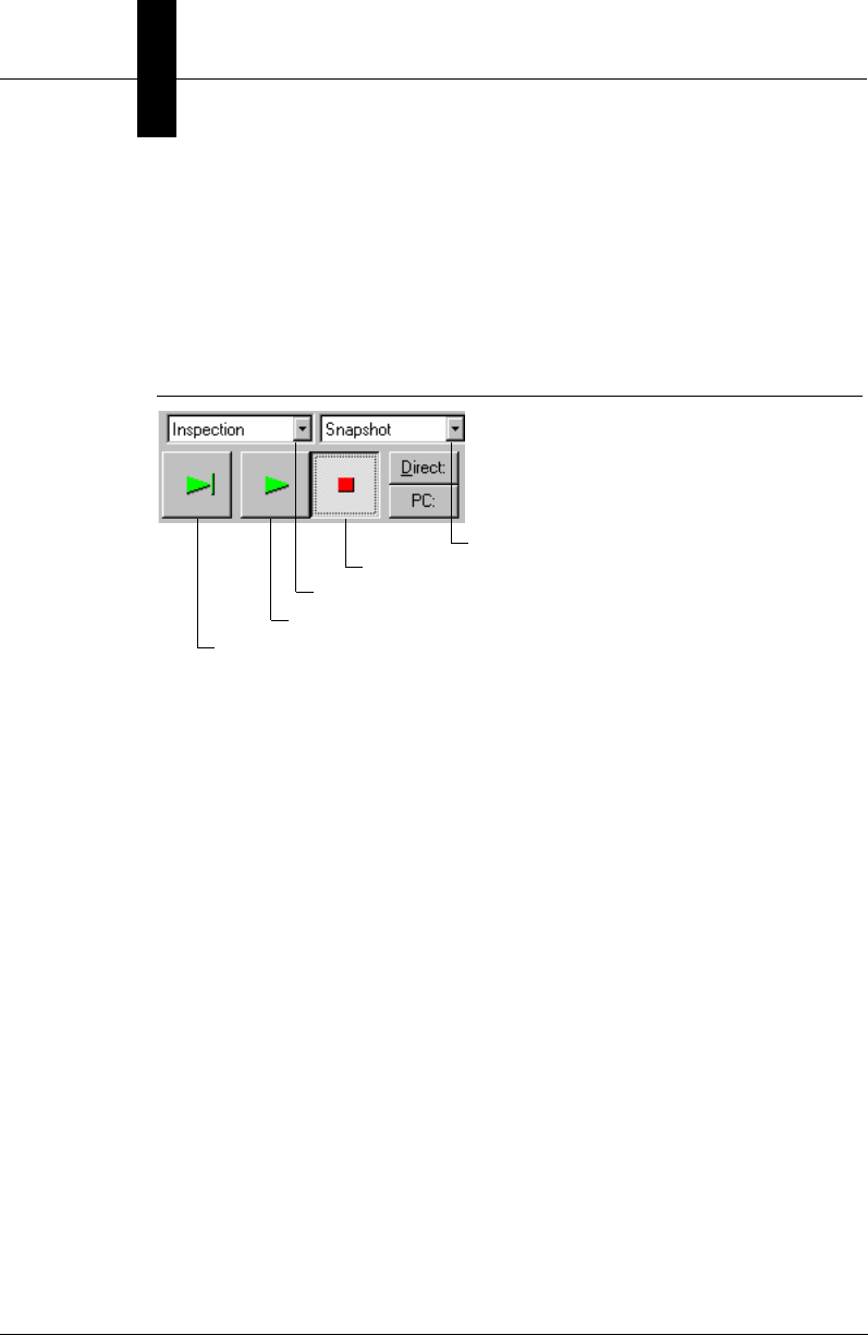
Appendix BLegacy Controls
B-22 Visionscape Programmer’s Kit (VSKit) Manual
Inspection Control
The Inspection Controls (Figure B–8) allow you to select an Inspection
and a Snapshot within that inspection, run the inspection once, start the
inspection, and then stop the inspection. The list of inspections is filled
from the job loaded on the target system.
FIGURE B–8. Inspection Control
When there is no job, the Inspection drop-down list is disabled with the
selection <none>. The Snapshot drop-down list includes the names of
snapshot steps in the selected inspection. When there are no snapshots,
this drop-down list is disabled with the selection <none>. Once an
inspection is selected, you can click any of the following:
• Run Once button — Execute the job once
• Start Inspection button — Run the inspection continuously
• Stop Inspection button — Stop the currently running inspection
Image Display Control
The Image Display Control contains two rows of buttons to set options for
specific display modes. The top row exclusively sets options for Direct
(Host) display, and the bottom row for remote PC display.
The Image Display Control buttons are shown in Figure B–9.
Run Once
Start Inspection
Stop Inspection
Inspections drop-down list
Snapshot drop-down list
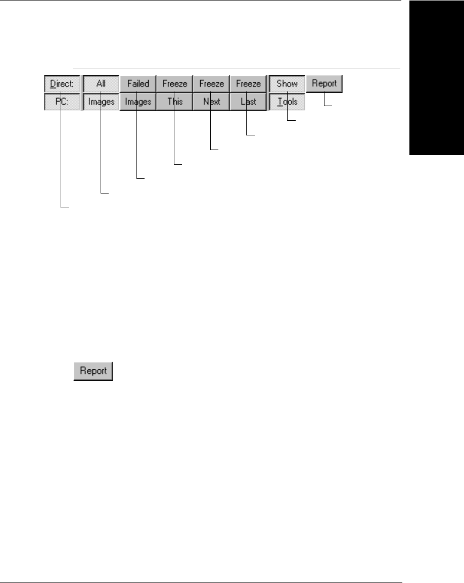
Runtime/Target Manager ActiveX Control
Legacy Controls
B
Visionscape Programmer’s Kit (VSKit) Manual B-23
FIGURE B–9. Image Display Control
These buttons allow you to perform the following:
• Select Direct or remote PC displays
• Display All Images or display only Failed Images
• Freeze This current image, Freeze Next failure, or Freeze Last failure
• Show/Hide Tool graphics
Report
Report enables or disables the direct display report.
Status Bar
The Status Bar (Figure B–10) is displayed at the bottom of the Runtime
Manager and contains informational controls.
Freeze Current Image
Select Direct or Remote (PC) Displays
Display All Images
Display Only Failed Images
Freeze Last Failure
Show/Hide Tool Graphics
Freeze Next Failure
Show Report
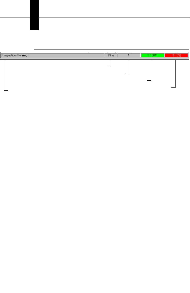
Appendix BLegacy Controls
B-24 Visionscape Programmer’s Kit (VSKit) Manual
FIGURE B–10. Runtime Manager Status Bar
The Status Bar contains a Task Information display, the current
Inspection Time in msec, the number of Total Inspections, the number of
Passed Inspections and Ratio, and the number of Failed Inspections and
Ratio.
Properties
Table B–12 summarizes the control properties of the Runtime/Target
Managers. The Control column identifies whether the property is
exclusive to one or common to both.
Task Information
Inspection Time in msec.
Total Inspections
Passed Inspections and Ratio
Failed Inspections and Ratio

Runtime/Target Manager ActiveX Control
Legacy Controls
B
Visionscape Programmer’s Kit (VSKit) Manual B-25
TABLE B–12. Control Properties
Name Control Type Description
ASICSpaceKBBank0 Both Long Memory in KB that must be available in
ASIC Bank 0 (as measured on the host
PC) in order to download the given job,
default is 1024 (1MB). Property of
embedded Target Manager.
ASICSpaceKBBank1 Both Long Memory in KB that must be available in
ASIC Bank 1 (as measured on the host
PC) in order to download the given job,
default is 1024 (1MB). Property of
embedded Target Manager.
bKeepLocalFailedImage RunMgr Boolean Controls the Freeze Last Failure
function operation. When this property
is True, a local copy of the last failed
image is maintained. This requires
some copying at runtime, which may
affect performance. It’s useful when
analyzing failures On-line. When
triggers are stopped and you select the
Freeze Last Failure option, the image is
immediately updated to the last failure.
When disabled, the image will not
change until the system receives the
next trigger.
BufMgr RunMgr _DBufMgr Dispatches the interface to the
embedded Buffer Manager control.
Callers can retrieve this interface and
call methods of the embedded Buffer
Manager. Property of embedded Target
Manager
ImageUploadBlocked RunMgr Boolean When True, the processor usage limit
has been surpassed and the last
uploaded image was thrown out.
ImageUploadProcessor
Limit
RunMgr Short Processor usage percentage limit at
which to block images from the host
image display. By default, this value is
92%. When the processor usage is
equal to or above 92%, images from
image upload are thrown out and the
ImageUploadBlocked value is set to
True.

Appendix BLegacy Controls
B-26 Visionscape Programmer’s Kit (VSKit) Manual
The control also echoes the properties of the contained Target Manager
control.
The methods pertaining to Runtime and/or Target Manager ActiveX
Controls are provided in the following tables:
• Table B–13, “User Interface Control Methods,” on page B-27
• Table B–14, “Connection Control Methods,” on page B-27
ImageUploadUseExEve
nt
RunMgr Boolean When True, the ImageUploadDoneEx
event is fired when new image(s) have
been uploaded. The images are not
rendered in the internal BufMgr.
Instead, they are returned as objects in
the event.
IOEventEnable Both Boolean When True, IO transition events are
enabled for all IO points. Property of
embedded Target Manager.
IOPhysInputCount Both Long Number of physical inputs (read-only)
IOPhysOutputCount Both Long Number of physical outputs (read-only)
IOVirtInputCount Both Long Number of virtual inputs
IOVirtOutputCount Both Long Number of virtual outputs (read-only).
MIPSSpaceKB Both Long Memory in KB that must be available in
MIPS memory (as measured on the
host PC) in order to download the given
job, default is 2048 (2MB). Property of
embedded Target Manager.
MIPSSpaceKB Both Long Dispatch interface to the embedded
Target Manager control. Callers can
retrieve this interface and call methods
of the embedded Target Manager.
ResultsUploadUseExEv
ent
Both Boolean When True, the ResultsUploadDoneEx
event is fired when new results are
uploaded.
TargetMgr RunMgr _DTarget Mgr Memory in KB that must be available in
MIPS memory (as measured on the
host PC) in order to download the given
job, default is 2048 (2MB).
TargetStep Both Long Handle of the current Target step in the
control
TABLE B–12. Control Properties
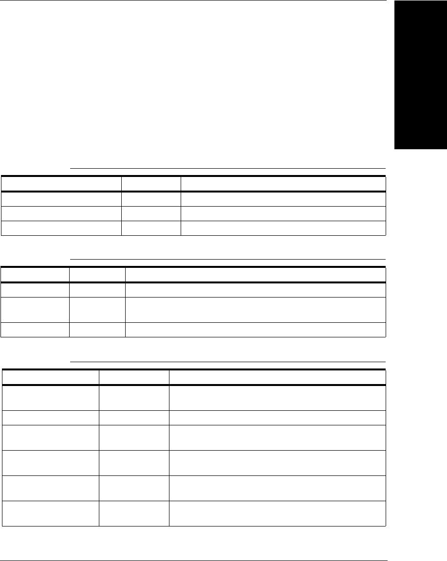
Runtime/Target Manager ActiveX Control
Legacy Controls
B
Visionscape Programmer’s Kit (VSKit) Manual B-27
• Table B–15, “Inspection Control Methods,” on page B-27
• Table B–16, “Image Display Methods,” on page B-29
• Table B–17, “Part Queue Methods,” on page B-30
• Table B–18, “Target Job Management Methods,” on page B-30
• Table B–19, “I/O Methods,” on page B-31
TABLE B–13. User Interface Control Methods
Name Control Description
EnableStatusDisplay RunMgr Shows/hides the Status Bar.
EnableToolbarDisplay RunMgr Shows/hides the Toolbar.
ShowResultsDisplay RunMgr Shows/hides the Results Display window.
TABLE B–14. Connection Control Methods
Name Control Description
Disconnect Both Disconnects the currently connected target system.
Edit Both Connects to the system and optionally downloads a given target
step.
IsConnected Both Returns a boolean on the connection status.
TABLE B–15. Inspection Control Methods
Name Control Description
CurrentInspection RunMgr Returns the index of the currently selected
inspection.
CurrentSnapshot RunMgr Returns the index of the currently selected snapshot.
IsInspectionRunning Both Returns a boolean on the running status of a specific
inspection on the target system.
ListInspections Both Returns an array of all the inspection names on the
target system.
ListSnapshots Both Returns an array of the snapshot names in the given
inspection on the target system.
NumberOfInspections Both Returns the number of inspections on the target
system.

Appendix BLegacy Controls
B-28 Visionscape Programmer’s Kit (VSKit) Manual
NumberOfSnapshots Both Returns the number of snapshots in the given
inspection on the target system.
ResetCounters Both Resets the part counters for the given inspection on
the target system.
RunOnce Both Runs the given inspection once on the target system.
RunOptionsGet Both Returns the current run options for given inspection.
The return value is 1 if calibrated results are turned
ON, 0 otherwise.
RunOptionsSet Both Sets the run options for given inspection (calibrated
results). Call can use the enum optCalibrated as the
second parameter to this call to ask this inspection to
send calibrated results.
SaveCurrentImage RunMgr Saves the currently displayed image.
SelectInspAndSnapB
yHandle
RunMgr Selects an inspection and snapshot by handles.
Useful only when the TargetStep is valid.
SelectInspectionAnd
Snapshot
RunMgr Selects an inspection and a snapshot.
SelectSnapshot RunMgr Selects a snapshot.
SetCounters Both Sets the part counters to the input values for the
given inspection on the target system.
Start Both Starts running the given inspection on the target
system.
StartAll RunMgr Starts all inspections on the target.
StartEx Both Starts running the given inspection on the target
system for a specified iteration.
StartInspection RunMgr Starts the current inspection.
Stop Both Stops running the given inspection on the target
system.
StopAll RunMgr Stops all inspections on the target.
StopInspection RunMgr Stops the current inspection.
TABLE B–15. Inspection Control Methods (continued)

Runtime/Target Manager ActiveX Control
Legacy Controls
B
Visionscape Programmer’s Kit (VSKit) Manual B-29
TABLE B–16. Image Display Methods
Name Control Description
DirectDisplayGetStatus Both Returns status information on the direct
display
ImageUploadGetExtendedStats RunMgr Uploads the extended statistics with the
image.
ImageUploadGetReport RunMgr Gets the InspectionReport object from
the ImageUpload mechanism. Call is
valid only from the ImageUploadDone
event.
ImageUploadGetMemoryStats RunMgr Returns target memory statistics from
the image upload
IsDisplayOn RunMgr Returns a boolean indicating whether
the direct or remote display is On.
IsGraphicsEnabled RunMgr Returns a boolean indicating whether
the tool graphics on the direct or remote
display is On.
IsHostDisplayStillActive TargetMgr Returns True if the given host display ID
is still active
IsTargetReportOn RunMgr Returns True if the direct display
inspection report is active
NewFreezeMode TargetMgr Sets the frozen display mode for the
direct and/or remote displays.
PixelBufToCtrl RunMgr Similar to the Buffer Manager API.
However, the control's client space is
the RuntimeMgr, not the BufMgr.
PixelCtrlToBuf RunMgr Similar to the Buffer Manager API.
However, the control's client space is
the RuntimeMgr, not the BufMgr.
SetFreezeFailMode RunMgr Sets the Freeze Image Display mode for
the direct or remote display, or both.
SetFreezeModeAllDisplays Both Sets the freeze mode for all displays for
an inspection
SetVideoDisplay RunMgr Activates/deactivates the direct or
remote display, or both.
ShowHostGraphics RunMgr Turns the tool graphics On/Off on the
remote display.
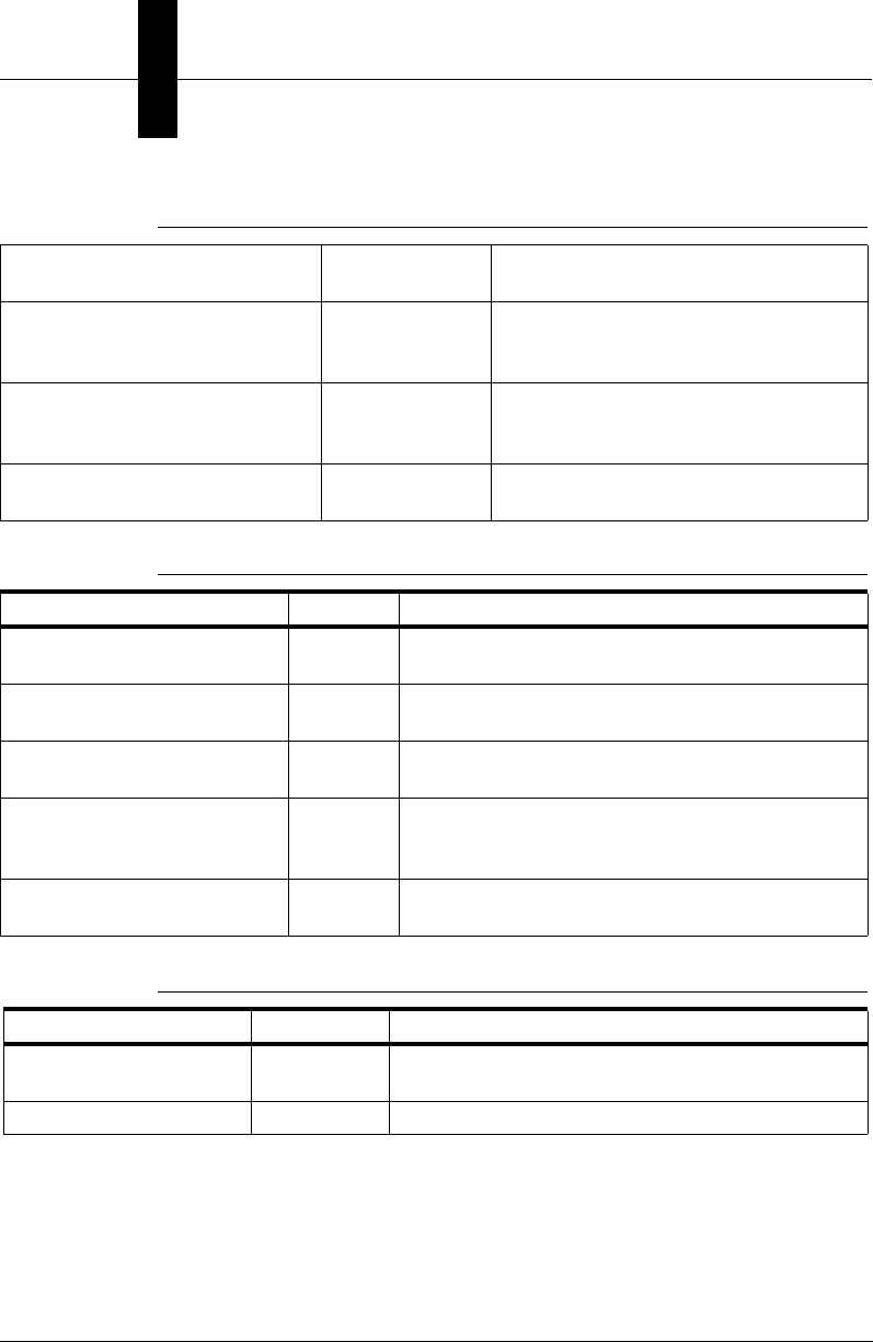
Appendix BLegacy Controls
B-30 Visionscape Programmer’s Kit (VSKit) Manual
ShowTargetGraphics RunMgr Turns the tool graphics On/Off on the
direct display.
ZoomIn RunMgr Magnifies the current image so the
display shows a smaller portion with
more resolution.
ZoomOut RunMgr Shrinks the current image so the display
shows a larger portion with less
resolution.
ZoomTo RunMgr Adjusts the resolution of the image to a
user-specified ratio.
TABLE B–17. Part Queue Methods
Name Control Description
ClearPartQueue Both Clears the Part Queue records for the given
inspection.
RetrieveAndSavePartImages Both Gets the queue of images from the target memory
into tif files on the host PC.
RetrievePartQueueEx Both Uploads the Part Queue records for the given
Inspection, then clears the records.
RetrievePartQueueRecord Both Uploads a specific Part Queue record from the
given inspection, either by queue index or cycle
count.
RetrievePartQueueSummary Both Uploads a summary of the Part Queue for the
given inspection.
TABLE B–18. Target Job Management Methods
Name Control Description
ActivateRuntimeDisplays TargetMgr Activates/deactivates direct and remote displays on
the target system.
DeactivateDisplay TargetMgr Deactivates the direct display of the target system.
TABLE B–16. Image Display Methods (continued)
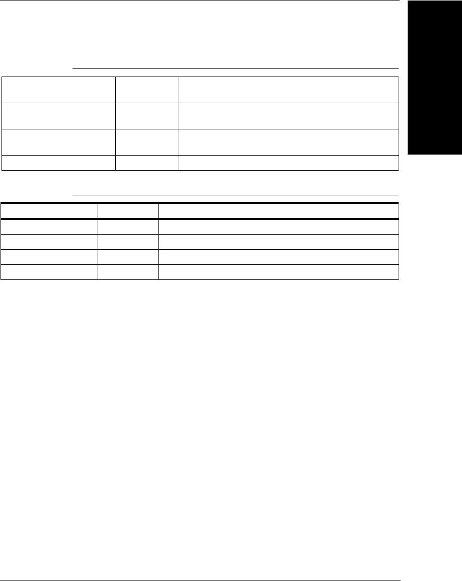
Runtime/Target Manager ActiveX Control
Legacy Controls
B
Visionscape Programmer’s Kit (VSKit) Manual B-31
Results Upload Methods
Results are a set of datums on the target that are uploaded to the host at
the end of each inspection. Each inspection has its own set of results.
When the results are uploaded to the host, the data is stored in a table
that includes the datum user name, symbolic name, GUID (type), and
value represented as a Variant. When results are activated for a particular
inspection, the control sends the ResultsUploadDone event, at which time
the caller must retrieve the data. Callers should retrieve the data into their
own memory structures and process the results later, either on a separate
thread or with a timer, in order to keep the event handler as fast as
Download Both Downloads a job file to the connected target system
with an asynchronous option.
DownloadIsComplete Both On an asynchronous download, return True when
the download has completed.
DownloadProgress Both Returns progression information on the current
asynchronous download
SpecialCommand Both Sends a special command to the target
TABLE B–19. I/O Methods
Name Control Description
IOGetPoint Both Gets a boolean value of a specific I/O point
IOSetPoint Both Sets a boolean value to a specific I/O point
IOVirtGetWord Both Gets a range of boolean Virtual I/O points
IOVirtSetWord Both Sets a range of boolean Virtual I/O points
TABLE B–18. Target Job Management Methods (continued)

Appendix BLegacy Controls
B-32 Visionscape Programmer’s Kit (VSKit) Manual
possible. Refer to the FrontRunner Visual Basic source code and the
ResultsUploadDone event handler description.
TABLE B–20. Results Upload Methods
Name Control Description
ResultsDisableUpload Both Disables results upload for a specific
inspection.
ResultsDisableUploadAll Both Disables results upload for all inspections.
ResultsEnableUpload Both Enables results upload for a specific
inspection.
ResultsEnableUploadAll Both Enables results upload for all inspections.
ResultsGetExtendedStat
s
Both Gets the basic inspection statistics as well as
cycle times, PPM, etc.
ResultsGetMemoryStats Both Retrieve memory statistics from the uploaded
results
ResultsGetNames Both Get the names of the datums in the set of
results.
ResultsGetOverallStats Both Get the pass/fail status and inspection counts
in the set of results.
ResultsGetReport Both Get the AvpInspReport object that contains all
the results. Call is valid only from the
ResultsUploadDone event.
ResultsGetValue Both Get a value in the set of results.
ResultsGetValueAll Both Get all values in the set of results.
ResultsPopLastFailed Both This API performs no function and is kept for
legacy purposes.
ResultsPopMostRecent Both . This API performs no function and is kept for
legacy purposes.
ResultsPopNext Both This API performs no function and is kept for
legacy purposes.
StringResultsDisableUplo
ad
Both Disables string results for a specific inspection
StringResultsDisableUplo
adAll
Both Disables string results for all inspections

Runtime/Target Manager ActiveX Control
Legacy Controls
B
Visionscape Programmer’s Kit (VSKit) Manual B-33
• long ActivateRuntimeDisplays(long dispNo, long inspNo, long
snapNo, long freezeMode, long displayMode, BSTR hostName, long
portNum, long dmaAddr);
This method activates or deactivates the direct/remote displays on
the target. The caller must specify the current display ID from the
target in dispNo or -1 on first-time activation. The display ID is an
identifier that corresponds to the running image upload thread on the
target.
The indices of the inspection and snapshot are specified in inspNo
and snapNo, respectively.
The Display Freeze Mode is set in freezeMode. The display modes
are:
– 0 — Display all images
– 1 — Display failed images only
StringResultsEnableUplo
ad
Both Enables string results for a specific inspection
StringResultsEnableUplo
adAll
Both Enables string results for all inspections
StringResultsOverrun Both When True, string results have “overrun”. That
is, the caller has taken too much time
processing the results and the next set of
results has been dropped. The overrun is
defined by the timeout parameter of
StringResultsEnableUpload
StringResultsOverrunCle
ar
Both Clears the string results overrun flag for the
specific inspection.
TABLE B–21. Data Retrieval Methods
Name Control Description
DatumGet Both Gets a named datum from the target.
DatumSet Both Sets a named datum value to the target.
TABLE B–20. Results Upload Methods

Appendix BLegacy Controls
B-34 Visionscape Programmer’s Kit (VSKit) Manual
– 2 — Freeze current image
– 3 — Freeze next failure
– 4 — Display last failure
This longword sets the freeze mode for the direct and remote displays
independently. The low byte of the longword specifies the failure
mode in the low seven bits. When the eighth bit is 1, it displays the
runtime tool graphics. The next to lowest byte specifies the remote
display mode.
The display mode is set in displayMode and is:
– 0 — Deactivate both displays
– 1 — Activate direct display only
– 2 — Activate host display only
– 3 — Activate both displays
hostName — The network name parameter of the host PC. This
name can be retrieved using the GetComputerName() Win32 API.
portNum — The unique port number parameter of the caller that is
used for the socket communication of the host image.
dmaAddr — The DMA address used for transferring the live image to
the host PC.
Return Values — The ID returned from the target to use in
subsequent calls of this method in dispNo. If no remote display is
activated, this value is always -1.
Error Codes — TARGMGR_E_NOCONNECT if no system is
connected.
• void ClearPartQueue(long inspIndex);
This method clears the Part Queue records for the given inspection.
Error Codes — TARGMGR_E_NOCONNECT if no system is
connected.
• long CurrentInspection();

Runtime/Target Manager ActiveX Control
Legacy Controls
B
Visionscape Programmer’s Kit (VSKit) Manual B-35
This method returns the zero-based index of the currently selected
inspection. The selected inspection and snapshot are used with the
remote image display.
• long CurrentSnapshot();
This method returns the zero-based index of the currently selected
snapshot. The selected inspection and snapshot are used with the
remote image display.
• VARIANT DatumGet(BSTR fullSymName, [optional] VARIANT
param);
This method retrieves and returns a specified datum value from the
connected target (e.g., Insp1.Snap1.Acq1.Trigger). The param
Variant value is datum-specific. Refer to “StepTreeView ActiveX
Control” on page 8-54 for more information.
Error Codes — TARGMGR_E_NOCONNECT if no system is
connected, or a datum-specific error code.
• void DatumSet(BSTR fullSymName, VARIANT* value, [optional]
VARIANT param);
This method sets a specified datum value on the connected target
(e.g., Insp1.Snap1.Acq1.Trigger) to a given Variant value. The format
of the data and the param Variant value is datum-specific. Refer to
“StepTreeView ActiveX Control” on page 8-54 for more information.
Error Codes — TARGMGR_E_NOCONNECT if no system is
connected, or a datum-specific error code.
• void DeactivateDisplay(long inspNo, long dispNo, long mode);
This method deactivates the display (either direct, remote or both) for
the given inspection. The inspNo is the inspection index; the dispNo
is the display ID returned from ActivateRuntimeDisplays(); and the
mode can be one of the following values:
– 0 — Deactivate both displays
– 1 — Activate direct display only
– 2 — Activate host display only
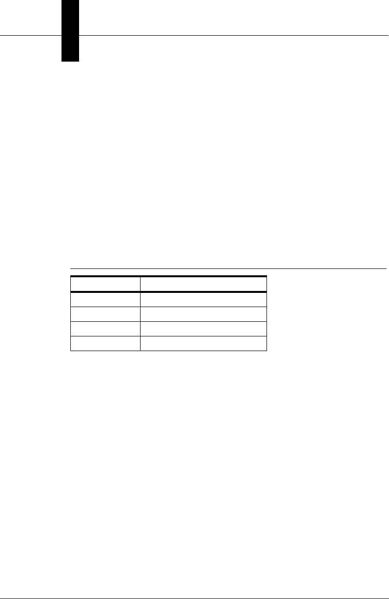
Appendix BLegacy Controls
B-36 Visionscape Programmer’s Kit (VSKit) Manual
– 3 — Activate both displays
Error Codes:
– TARGMGR_E_NOCONNECT if no system is connected
– TARGMGR_E_BADINSPINDEX if the inspection index is invalid
• VARIANT DirectDisplayGetStatus(long inspIndex, long snapIndex);
This method returns the status of the direct display for the given
inspection and snapshot index. The Variant returned is a Variant
array with the members shown in Table B–22.
Error Codes:
– TARGMGR_E_BADINSPINDEX
– TARGMGR_E_BADSNAPINDEX
– TARGMGR_E_NOCONNECT
• void Disconnect();
This method disconnects the currently connected target system.
Error Codes — None
• void Download(VARIANT programName, bool bAsync);
This method downloads a given job to the target system with an
asynchronous option. The programName VARIANT is either a String
variant containing the full path to the job or a long variant containing
the handle of the TargetStep to download to the device. Downloading
TABLE B–22. Variant Array with Members
Array Index Data
0 True if display is active
1 Freeze Mode of the display
2 True if reports are on
3 True if graphics are on

Runtime/Target Manager ActiveX Control
Legacy Controls
B
Visionscape Programmer’s Kit (VSKit) Manual B-37
a new job causes virtual I/O connections to be reset and Result
Upload connections to be cleared. If bAsync is set to True, the
download occurs asynchronously. That is, the function returns
immediately after the connection to the target is made and it’s up to
the caller to use the DownloadIsComplete API to check the status of
the download. When using the asynchronous download, callers
cannot call any other API in the control until the download is
complete.
When downloading a TargetStep, the job is scanned for Perl Steps
and instances of FileSpecDm. Files are required on the target for
these steps and datums. Therefore, the control creates one or more
RAM disks on the target called /perld0 for the Perl Steps and /filesd0
for the FileSpecDm. Any files required by these steps and datums are
transferred to the appropriate RAM drives using FTP (a simple
progression window is shown while this is happening). Once on the
target, the steps/datums in the program are automatically altered to
point to the target RAM drive rather than the local hard disk.
Currently, FileSpecDm is used by Acquire to store the list of files to be
used when loading images from file rather than from camera. With
this functionality, these images are automatically loaded to the target.
On the host, memory is measured to prevent illegal downloads to the
target. Both ASIC banks are tracked in the job for the specific Target.
These values are compared against the size of the ASIC banks
before download. When the difference between the size of each bank
and the overall high ASIC usage in the job on each bank is less than
the ASICSpaceKBBank0 or ASICSpaceKBBank1 properties, the
download is aborted. The MIPS memory is not accurately measured
at this time and is not checked at download time.
Error Codes:
– E_INVALIDARG if the Variant is an illegal type
– TARGMGR_E_NOTTARGETSTEP if the given handle is not a
TargetStep
– TARGMGR_E_NOCONNECT if no system is connected
– TARGMGR_E_NOTINDNLOAD
– TARGMGR_E_NOTHREAD

Appendix BLegacy Controls
B-38 Visionscape Programmer’s Kit (VSKit) Manual
– TARGMGR_E_NOFTPCONNECT
– TARGMGR_E_NOHOSTLOOKUP
– TARGMGR_E_REENTRANCY
– TARGMGR_E_NODNLOADCONNECT
– TARGMGR_E_FTPFAILED
– TARGMGR_E_DNERRINIT
– TARGMGR_E_DNERRTARGCLEANUP
– TARGMGR_E_DNERRSTREAMING
– TARGMGR_E_DNERRPREPARERUN
– TARGMGR_E_DNERRCONNECTING
– TARGMGR_E_DNERRDISCONNECTING
– TARGMGR_E_DNERRNOTARGMEMSTATS
– TARGMGR_E_DNERRSPACEBANK0
– TARGMGR_E_DNERRSPACEBANK1
– E_FAIL on a general failure
Perl or FileSpecDm transfers can generate these errors:
–TARGMGR_E_NOPERLMODROOT
– TARGMGR_E_NOPERLSCRIPTS
– ARGMGR_E_NOMAKEPERLDRV
– TARGMGR_E_FTPXFERFAILED
– TARGMGR_E_TJOBPERLCMDFAILED
– TARGMGR_E_FSPECNOFILES
– TARGMGR_E_TJOBFILESPECCMDFAILED
• bool DownloadIsComplete();

Runtime/Target Manager ActiveX Control
Legacy Controls
B
Visionscape Programmer’s Kit (VSKit) Manual B-39
This method returns True when the asynchronous download is
complete. Any errors that have occurred during the download are
thrown when this method is called.
Error Codes:
– TARGMGR_E_NOTINDNLOAD
– TARGMGR_E_NOTHREAD
– TARGMGR_E_NOFTPCONNECT
– TARGMGR_E_NOHOSTLOOKUP
– TARGMGR_E_NOCONNECT

Appendix BLegacy Controls
B-40 Visionscape Programmer’s Kit (VSKit) Manual
• VARIANT DownloadProgress()
This method returns progression information on the current
asynchronous download. This method is valid only if a streamed,
asynchronous download is in progress. The information is a Variant
array with the following members, as listed in Table B–23.
• long Edit(BSTR strSystem, VARIANT lJob, bool bAsync);--RunMgr
This method connects to the given network device in strSystem and
optionally downloads any TargetStep given in lJob. When the lJob is
given, the TargetStep property is set to this job, and you can no
longer select a different file to be downloaded to the device. In
essence, the control takes on the Runtime connection of the job.
When bAsync is True, the download is asynchronous. That is, the
download is launched as a separate thread and the function returns
immediately. Callers must then use DownloadIsComplete to validate
the completion of the download.
TABLE B–23. Variant Array with Members
Array Index Value Data
0 State Current state of the download:
0 - Initializing
1 - Streaming data In
2 - Streaming data Out
3 - Fixing up job after streaming
4 - Executing PostStream
5 - Complete
1 Handle Handle of the Composite object being streamed.
2 Handle Handle of the Step object being streamed.
3 Total Objects Total number of objects to be streamed.
4 Num Objects Current number of objects streamed.
5 Total Bytes Total number of bytes to be streamed.
6 Num Bytes Number of bytes streamed.
7 Total Steps Total number of steps to be streamed.
8 Num Steps Number of steps currently streamed.
9 Total Step Bytes Total number of step bytes to be streamed.
10 Num Step Bytes Number of step bytes currently streamed.

Runtime/Target Manager ActiveX Control
Legacy Controls
B
Visionscape Programmer’s Kit (VSKit) Manual B-41
• void Edit(BSTR targetName);--TgtMgr
This method connects to the given target system. The targetName is
the target system's network name.
Error Codes:
– TARGMGR_E_NOCONNECT if no system connects
– TARGMGR_E_NORPCCONNECT if the RPC proxies could not
connect
– E_FAIL on a general failure
• void EnableStatusDisplay(boolean bEnable);
This method shows or hides the Status Bar. The Status bar is hidden
when bEnable is False; it’s displayed when bEnable is True.
Error: E_OUTOFMEMORY, or E_FAIL on a general error.
• void EnableToolbarDisplay(boolean bEnable);
This method shows or hides the Toolbar. The Toolbar is hidden when
bEnable is False; it’s displayed when bEnable is True.
Error Codes:
–E_OUTOFMEMORY
– E_FAIL on a general error.
• VARIANT GetTargetSystems();
This method returns a variant array of the network names of all the
local target devices in the host PC.
Error Codes:
–E_OUTOFMEMORY
– E_FAIL on a general error.

Appendix BLegacy Controls
B-42 Visionscape Programmer’s Kit (VSKit) Manual
• VARIANT ImageUploadGetExtendedStats();
This method retrieves the extended statistics uploaded with the
image when remote image display is activated. It returns a variant
array with the members shown in Table B–24.
Error Codes — E_OUTOFMEMORY if no memory can be allocated
for the array.
• IAvpInspReport* ImageUploadGetReport();
This method returns an AvpInspReport object containing the statistics
and image uploaded. This call is valid only from the
ImageUploadDone event. See the “Inspection Report Details” on
page 6-17 for details on this object.
• void ImageUploadGetMemoryStats(VARIANT* vMIPS, VARIANT*
vBank0, VARIANT* vBank1);
This method returns memory statistics for the target that are
uploaded with the image. This report is exactly the same as that
returned in ResultsGetMemoryStats.
TABLE B–24. Variant Array with Members
Array Index Data
0 Inspection Pass/Fail (1/0)
1 Total number of inspections
2 Number of passed inspections
3 Execution time of inspection (ms)
4 Time (ms) from the end of the last inspection to the end of
this one
5 Longest cycle time for this inspection
6 Inspection rate (ppm)
7 Fastest inspection rate (ppm)
8 Longest time (ms) taken by inspection processing
9 Time (ms) spent updating the target display
10 Time (ms) spent by the steps' draw routines
11 Cumulative time (ms) spent waiting in all snapshots

Runtime/Target Manager ActiveX Control
Legacy Controls
B
Visionscape Programmer’s Kit (VSKit) Manual B-43
• short IOGetPoint(long IONumber);
This method returns the state of a specific I/O point. Physical I/O is
numbered from 1 to 16, and virtual I/O from 101 to 164.
Error Codes — TARGMGR_E_NOVIRUTALIO if virtual I/O is not
connected.
• void IOSetPoint(long IONumber, short IOState);
This method sets the state of a specific I/O point. Physical I/O is
numbered from 1 to 16, and virtual I/O from 101 to 164.
Error Codes — TARGMGR_E_NOVIRUTALIO if virtual I/O is not
connected.
• long IOVirtGetWord(long StrtIONumber, long StopIONumber);
This method returns a range of virtual I/O states. The I/O range is
specified from StrtIONumber to StopIONumber. Physical I/O is
numbered from 1 to 16, and virtual I/O from 101 to 164.
Error Codes — TARGMGR_E_NOVIRUTALIO if virtual I/O is not
connected.
• void IOVirtSetWord(long StrtIONumber, long StopIONumber, long
lState);
This method sets a range of virtual I/O states to a given longword
state. The I/O range is specified from StrtIONumber to
StopIONumber. Physical I/O is numbered from 1 to 16 and virtual I/O
from 101 to 164.
Error Codes — TARGMGR_E_NOVIRUTALIO if virtual I/O is not
connected.
• bool IsConnected();
This method returns a boolean of the current connection state.
• bool IsDisplayOn(short flags);
This method returns a Boolean value indicating the display state of
the remote or direct display. The flags value can either be dispDirect
or dispRemote.

Appendix BLegacy Controls
B-44 Visionscape Programmer’s Kit (VSKit) Manual
Error Codes — E_OUTOFMEMORY, or E_FAIL on a general error.
• bool IsGraphicsEnabled(EDisplayType flags);
This method returns a boolean value indicating the tool graphics
display state of the remote or direct display. The flags value can either
be dispDirect or dispRemote.
Error Codes — E_OUTOFMEMORY, or E_FAIL on a general error.
• bool IsInspectionRunning(long inspNo);
This method returns a boolean of the running state of inspNo
inspection index.
Error Codes:
– TARGMGR_E_NO_CONNECT if there is no connection
– TARGMGR_E_BADINSPINDEX if the inspection index is invalid.
• bool IsTargetReportOn();
This method returns True if the direct display inspection report is
active.
• VARIANT ListInspections();
This method returns a two-dimensional VARIANT array of inspection
names and a boolean value for each inspection indicating the running
state of the inspection.
Error Codes — TARGMGR_E_NOCONNECT if there is no
connection.
• VARIANT ListSnapshots(long inspNo);
This method returns a VARIANT array of names of all the snapshots
in the given inspection. The inspection index is given in inspNo and
the array returns in inspInfo.
Error Codes:
– TARGMGR_E_BADINSPINDEX if the inspection index is illegal
– TARGMGR_E_NOCONNECT if there is no connection.

Runtime/Target Manager ActiveX Control
Legacy Controls
B
Visionscape Programmer’s Kit (VSKit) Manual B-45
• void NewFreezeMode(long inspNo, long dispNo, long dispMode);
This method sets the frozen display state of the given dispMode:
– 1 — For direct display
– 2 — For remote display
–3 — For both
The inspNo is the inspection index and dispNo is the display ID
returned in ActivateRuntimeDisplays().
Error Codes:
– TARGMGR_E_BADINSPINDEX if the inspection index is illegal
– TARGMGR_E_NOCONNECT if there is no connection.
• long NumberOfInspections();
This method returns the number of inspections on the target system.
Error Codes — TARGMGR_E_NOCONNECT if there is no
connection.
• long NumberOfSnapshots(long inspNo);
This method returns the number of snapshots in the given inspection.
Error Codes:
– TARGMGR_E_BADINSPINDEX if the inspection index is illegal
– TARGMGR_E_NOCONNECT if there is no connection.
• void PixelBufToCtrl(short* xPixel, short* yPixel);
This method converts given pixel values in the buffer space to the
control's client space. Zooming and scrolling are taken into effect.
Control space is the Runtime Manager control, not the embedded
Buffer Manager control.
• void PixelCtrlToBuf(short* xPixel, short* yPixel);
This method converts given pixel values in the control's client space
to buffer space. Zooming and scrolling are taken into effect. Control

Appendix BLegacy Controls
B-46 Visionscape Programmer’s Kit (VSKit) Manual
space is the Runtime Manager control, not the embedded Buffer
Manager control.
• void ResetCounters(long inspectionNo);
This method resets the count of total and passed parts for the given
inspection. Counters must only be reset when the inspection is
stopped.
Error Codes:
– TARGMGR_E_BADINSPINDEX if the inspection index is illegal
– TARGMGR_E_NOCONNECT if there is no connection
– E_FAIL on a general failure
• void ResultsDisableUpload(long inspNo);
This method disables the results upload from the target system. The
inspNo is the inspection index to disable.
• void ResultsDisableUploadAll();
This method disables all result upload threads that have been started.
• void ResultsEnableUpload(long inspectionNo, VARIANT
timeoutValue);
This method enables the results upload stream for the given
inspection (inspectionNo) on the target system. Once enabled, at the
end of each inspection the set of results in the InspectionResultsDm
tagged for upload are sent from the target to the host. The
ResultsUploadDone event is then sent to the owner of the control, at
which time the results can be read from the control. The timeoutValue
determines the blocking mode of the results upload mechanism. If 0,
timeouts are not used and the results upload worker thread is blocked
with the next results until the main thread (e.g., Visual Basic
application) processes the current results in the ResultsUploadDone
event handler. If a timeout value is specified (msec), the worker
thread blocks with the next results waiting for the main thread to
process the current set of results up to the timeout value specified. If
the timeout is reached, the new results are thrown out and the
ResultsOverrun signal is set. The Overrun signal is reset only by
ResultsOverrunClear.

Runtime/Target Manager ActiveX Control
Legacy Controls
B
Visionscape Programmer’s Kit (VSKit) Manual B-47
Error Codes:
– TARGMGR_E_NOCONNECT if no system is connected
– TARGMGR_E_BADINSPINDEX if the given inspection index is
illegal
– TARGMGR_E_NOINSPS if there are no inspections from which
to retrieve results
– E_OUTOFMEMORY if a results upload thread cannot be
allocated on the host PC
– E_FAIL on a general failure
• void ResultsEnableUploadAll(VARIANT timeoutValue);
This method enables results upload for all inspections on the target.
Error codes from ResultsEnableUpload apply.
• VARIANT ResultsGetExtendedStats(long inspectionNo);
This method returns a Variant array containing a set of inspection
statistics in the latest results, as well as extended statistics, as listed
in Table B–25.
TABLE B–25. Variant Array with Member Description
Array Index Member Description
0 True if inspection passed, False if not
1 Total number of inspections
2 Number of passed inspections
3 Execution time of inspection (ms)
4 Time (ms) from the end of the last inspection to the end of this one
5 Longest cycle time for this inspection
6 Inspection rate (ppm)
7 Fastest inspection rate (ppm)
8 Longest time (ms) taken by inspection processing
9 Time (ms) spent updating the target display
10 Time (ms) spent by the steps' draw routines
11 Cumulative time (ms) spent waiting in all snapshots

Appendix BLegacy Controls
B-48 Visionscape Programmer’s Kit (VSKit) Manual
Error Codes:
– E_OUTOFMEMORY if memory cannot be allocated for the
returned data
– TARGMGR_E_NORESULTS if there are no results
– E_FAIL on a general failure
• void ResultsGetMemoryStats(long inspectionNo, VARIANT* vMIPS,
VARIANT* vBank0, VARIANT* vBank1);
This method retrieves the memory statistics information from the last
set of uploaded results for inspectionNo. The method returns memory
information for MIPS memory, as well as ASIC memory on bank 0
and bank1. The information is returned in Variant arrays, as shown in
Table B–26 and Table B–27.
12 Primary Error code of current inspection
13 Secondary Error code of current inspection
14 Symbolic name of Datum/Step that caused the error
15 Primary Error code of first error that occurred on this inspection
16 Secondary Error code of first error ever that occurred on this inspection
17 Symbolic name of Datum/Step that caused the first error ever
18 Primary Error code of first error occurring on any inspection
19 Secondary Error code of first error that occurred on any inspection
20 Primary Error code of last error that occurred on any inspection
21 Secondary Error code of last error that occurred on any inspection
TABLE B–26. Variant Array with Mips Data
Array Index MIPS Data in bytes
0 Size of memory
1 Total used memory
2 Memory used for Kernel
TABLE B–25. Variant Array with Member Description (continued)

Runtime/Target Manager ActiveX Control
Legacy Controls
B
Visionscape Programmer’s Kit (VSKit) Manual B-49
For MIPS memory, the memory used for each subcategory is a
breakdown of the total memory allocated. For each ASIC bank, total
used memory is the permanent plus temporary allocations. The
Buffer Pool is always allocated as permanent memory. Error codes
from ResultsEnableUpload apply.
• VARIANT ResultsGetNames(long inspectionNo, LPCTSTR
datumType);
This method returns a Variant array of datum names for the latest
results of the given inspection index. The datumType parameter
specify a specific type of datum in the list of results (e.g.,
Datum.Status, Datum.Int). To get all the names in the results list,
pass an empty string (e.g., "") as this parameter.
Error Codes:
– TARGMGR_E_BADINSPINDEX if the given inspection index is
illegal
– TARGMGR_E_NORESULTSOFID if there are no results of the
given type
3 Memory for RAM drive space
4 Memory for VX Modules
5 Memory for job tree
6 Max total memory used
TABLE B–27. Variant Array with Bank Data
Array Index Bank Data in bytes
0 Size of bank memory
1 Total used memory
2 Memory used for permanent allocation
3 Memory for Buffer Pool allocation
4 Memory for Temporary allocation
5 Max total bank memory used
TABLE B–26. Variant Array with Mips Data

Appendix BLegacy Controls
B-50 Visionscape Programmer’s Kit (VSKit) Manual
– E_OUTOFMEMORY if memory for the data cannot be allocated
on the host PC
– E_FAIL on a general failure
• VARIANT ResultsGetOverallStats();
This method returns the overall statistics in the latest results as a
VARIANT array. The array has four longword entries:
– 0 — 0 or 1 reflecting the pass/fail status of the inspection
– 1 — Number of passed inspections
– 2 — Number of total inspections
– 3 — Execution time of the inspection in msec
Error Codes:
– E_OUTOFMEMORY if memory cannot be allocated for the
returned data
– TARGMGR_E_NORESULTS if there are no results
– E_FAIL on a general failure
• IAvpInspReport* ResultsGetReport(long inspIndex);
This method returns the AvpInspReport object for the given
Inspection. All results are encapsulated in this object and this method
is valid only from the ResultsUploadDone event.
Returns: A reference to the AvpInspReport object or NULL if there is
no object.
• VARIANT ResultsGetValue(long inspectionNo, LPCTSTR
datumNameOrType, long index, short flags, VARIANT vErrorCode);
This method returns a Variant value from the latest results containing
the data for the given results Datum. The caller can retrieve data by
Datum type and index, general index, or specifically by name. The
flags parameter specifies this value (resBySymName,
resByDatumTypeAndIndex, resByOverallIndex). The
datumNameOrType parameter is a string containing either the name
of the datum in the list or the datum type. The index parameter is

Runtime/Target Manager ActiveX Control
Legacy Controls
B
Visionscape Programmer’s Kit (VSKit) Manual B-51
either the overall index if no name is specified or the index by type if
the type is specified. If an error has occurred in the Datum or its Step
owner, an empty Variant value is returned and the longword error
code is returned in vErrorCode.
The Variant return value is specific to the type of datum retrieved.

Appendix BLegacy Controls
B-52 Visionscape Programmer’s Kit (VSKit) Manual
Error Codes:
– TARGMGR_E_DATUMNOTOFOUND if the datum is not found in
the list
– TARGMGR_E_NORESULTS if there are no results
– E_OUTOFMEMORY if memory for the data cannot be allocated
on the host PC
• bool ResultsOverrun(long inspectionNo);
This method returns True if an overrun has occurred in the uploading
of results for the inspection given by inspectionNo in non-blocking
mode only. Use ResultsOverrunClear to reset the signal.
• void ResultsOverrunClear(long inspectionNo);
This method clears the ResultsOverrun signal for inspectionNo.
• void ResultsPopLastFailed(long inspectionNo);
This method performs no function and is kept for legacy purposes
only.
Error Codes:
– TARGMGR_E_BADINSPINDEX if the inspection index is illegal
– TARGMGR_E_NORESULTS if there are no results
– E_FAIL on a general failure
• void ResultsPopMostRecent(long inspectionNo);
This method performs no function and is kept for legacy purposes
only.
Error Codes:
– TARGMGR_E_BADINSPINDEX if the inspection index is illegal
– TARGMGR_E_NORESULTS if there are no results
– E_FAIL on a general failure
• void ResultsPopNext(long inspectionNo);

Runtime/Target Manager ActiveX Control
Legacy Controls
B
Visionscape Programmer’s Kit (VSKit) Manual B-53
This method performs no function and is kept for legacy purposes
only.
Return Values — S_OK on success, TARGMGR_E_BADINSPINDEX
if the inspection index is illegal, or E_FAIL on a general failure.
• void RetrieveAndSavePartImages(long inspNo, long baseNum,
BSTR path) - TgtMgr
This method gets the queue of saved images for the given inspection
from the target memory into .tif images on the host PC. The user
specifies a base path name and a base number. The image from the
first camera on the most recent part will receive the name pathnna.tif,
where:
– path — Indicates input path
– nn — Indicates input baseNum
– a — Indicates first camera
Error Codes:
– TARGMGR_E_NOIMAGES if the image queue is empty
– TARGMGR_E_NOCONNECT if there is no connection
– E_FAIL on a general failure
• void RetrieveAndSavePartImages(long baseNum, BSTR path); -
RunMgr
This method is similar to the Target Manager API. It retrieves the part
image queue for the current inspection, rather than for any inspection.
Error Codes:
– TARGMGR_E_NOIMAGES if the image queue is empty,
– TARGMGR_E_NOCONNECT if there is no connection
– E_FAIL on a general failure.
• IAvpInspReportCollection* RetrievePartQueueEx(long inspIndex);

Appendix BLegacy Controls
B-54 Visionscape Programmer’s Kit (VSKit) Manual
This method uploads the Part Queue records for the given Inspection,
then clears the records. The records are contained in a collection of
AvpInspReport objects.
• IAvpInspReport* RetrievePartQueueRecord(long inspIndex, long
indexOrCycleCount);
This method uploads a specific Part Queue record from the given
inspection, either by queue index or cycle count. If no record exists, a
PARTQ_E_BADRECORDID error is thrown.
• void RetrievePartQueueSummary(long inspIndex, long* isOn, long*
maxEntries, long* curEntries, VARIANT* overallStats);
This method uploads a summary of the Part Queue for the given
inspection. The isOn value indicates whether or not the Part Queue is
active. The maxEntries value indicates the maximum number of
records to store. The curEntries value indicates the current number of
records available. The overallStats value is an array of AvpInspStats
objects that indicates the pass/fail status and cycle counts for each
record in the queue.
• void RunOnce(long inspNo, long dispNo);
This method runs the given inspection once. It includes Target
Manager parameters. The dispNo is the display ID returned from
ActivateRuntimeDisplays().
Error Codes:
– TARGMGR_E_JOBISRUNNING if the job is already running
– TARGMGR_E_BADINSPINDEX if the inspection index is illegal
– TARGMGR_E_NOCONNECT if there is no connection
– E_FAIL on a general failure
• long RunOptionsGet (long inspectionNo);
This method retrieves the run option flags for the given inspection.
Valid result include OptCalibrated(1). When 1, the given inspection
uploads calibrated results. When 0, the given inspection uploads raw
pixel results.

Runtime/Target Manager ActiveX Control
Legacy Controls
B
Visionscape Programmer’s Kit (VSKit) Manual B-55
Error Codes:
– TARGMGR_E_BADINSPINDEX if the inspection index is illegal
– TARGMGR_E_NOCONNECT if there is no connection
– E_FAIL on a general failure
• void RunOptionsSet (long inspectionNo, long optionFlags);
This method sets run option flags for the given inspection. Valid flags
include OptCalibrated, when optionFlags is set to this value. All
results selected for upload in the given inspection are converted to
calibrated units before being uploaded to the Host.
If the camera(s) for that inspection have been calibrated, the results
are in world units (mm or inches) for all results. If the cameras have
not been calibrated, the results are converted to camera pixel
coordinates of the snapshot in which it’s inserted.
When optionFlags is set to 0, raw results are returned and stay in the
coordinate system of the image into which the tool is calculated.
Error Codes:
– TARGMGR_E_BADINSPINDEX if the inspection index is illegal
– TARGMGR_E_NOCONNECT if there is no connection
– E_FAIL on a general failure
• void SaveCurrentImage(BSTR strFileName);
This method saves the currently displayed image to the given file
name. The image is stored in .tif format.
Errors Codes — Refer to “Buffer Manager ActiveX Control” on
page 8-2 for more information on long SaveCurrentImage(BSTR
strFileName);.
• void SelectInspAndSnapByHandle(HSTEP hInsp, HSTEP hSnap);
This method selects an inspection and snapshot in the current
TargetStep by handle. It searches and selects the TargetStep for the
corresponding inspection and snapshot based on the current index
from the TargetStep.

Appendix BLegacy Controls
B-56 Visionscape Programmer’s Kit (VSKit) Manual
Error Codes:
– RUNMGR_E_NOTARGETSTEP if the TargetStep is invalid
– E_INVALIDARG, E_POINTER
– E_FAIL on general errors
• void SelectInspectionAndSnapshot(long inspectionno, long
snapshotno);
This method selects a particular inspection and snapshot for the
remote display. The zero-based index of the inspection and snapshot
are given in inspectionno and snapshotno, respectively.
Error Codes:
– Target Manager connection errors
– E_FAIL on a general failure.
• void SelectSnapshot(short snapshotno);
This method selects a particular snapshot within an inspection for the
remote display. The snapshotno value is the zero-based index of the
snapshot to select.
Error Codes:
– Target Manager connection errors
–E_OUTOFMEMORY
– E_FAIL on a general failure.
• long SetCounters(long inspectionNo, long lTotalInsp, long lPassInsp);
This method sets the count of total and passed parts to the input
values for the given inspection. Counters must only be set when the
inspection is stopped.
Error Codes:
– TARGMGR_E_BADINSPINDEX if the inspection index is illegal.
– E_FAIL on a general failure.

Runtime/Target Manager ActiveX Control
Legacy Controls
B
Visionscape Programmer’s Kit (VSKit) Manual B-57
• void SetCounters(long inspectionNo, long 1TotalInsp, long
1PassInsp);
This method sets the count of the number of total and passed parts to
the input values for the given inspection. Do not set counters until the
inspection is stopped.
Errors Codes:
– TARGMGR_E_BADINSPINDEX if the inspection index is illegal
– E_FAIL on a general failure
• void SetFreezeFailMode(short nFlag, short mode);
This method sets the frozen display mode of the direct or remote
display, or both. The nFlag value can be one of the following:
– 1 — For direct display
– 2 — For remote display
– 3 — For both direct and remote
The mode value can be one of the following:
– 0 — Display all images
– 1 — Display failed images only
– 2 — Freeze current image
– 3 — Freeze next failure
– 4 — Display last failure
Error Codes:
–E_OUTOFMEMORY
– E_FAIL on a general failure
• void SetFreezeModeAllDisplays(long inspNo, long freezeMode);
This method sets the freeze mode for all displays for inspection
inspNo to freezeMode.

Appendix BLegacy Controls
B-58 Visionscape Programmer’s Kit (VSKit) Manual
Errors Codes:
– TARGMGR_E_BADINSPINDEX
– TARGMGR_E_NOCONNECT
• void SetVideoDisplay(EDisplayType dispType);
This method activates or deactivates the remote or direct display, or
both. The dispType value can be dispNone, dispDirect, dispRemote,
or dispBoth.
Error Codes:
–E_OUTOFMEMORY
– E_FAIL on a general failure.
• long ShowExtendedResultsDialog(boolean bShow);
This method shows/hides the extended results dialog.
• void ShowHostGraphics(boolean bUp);
This method activates or deactivates the tool graphics on the remote
display. The turnOn value indicates the state.
Error Codes:
–E_OUTOFMEMORY
– E_FAIL on a general failure.
• void ShowResultsDisplay(boolean bUp);
This method shows or hides the Results Display window. The bUp
value indicates the state.
• long ShowTargetGraphics(boolean bUp);
This method activates or deactivates the tool graphics on the direct
display. The turnOn value indicates the state.
Error Codes:
–E_OUTOFMEMORY

Runtime/Target Manager ActiveX Control
Legacy Controls
B
Visionscape Programmer’s Kit (VSKit) Manual B-59
– E_FAIL on a general failure.
• long SpecialCommand(ESpecialCommand command, [optional]
VARIANT vParam);
This method sends a special command to the target. Current
commands include the ability to clear the files from the Perl RAM
drive, FileSpecDm RAM Drive, and get the current overall available
memory from the target.
Error Codes — E_FAIL if the command fails.
• long Start(long inspectionNo);
This method starts the given inspection on the target.
Error Codes:
– TARGMGR_E_JOBISNOTRUNNING if the inspection could not
be started
– TARGMGR_E_BADINSPINDEX if the inspection index is illegal
– TARGMGR_E_NOCONNECT if there is no connection
– E_FAIL on a general failure
• void StartAll();
This method initiates running all inspections on the target.
• long StartEx(long inspectionNo, long dispId, long howMany, boolean
bAsync);
This method starts a given inspection with more control by the caller.
The inspection is given in inspectionNo:
– dispId — Display ID returned from ActivateRuntimeDisplays()
– howMany — Count of the number of iterations to run
– bAsync — Indicates whether the job is spawned into a separate
task on the target
When it’s True, you can run the job in a separate vision system task
in multiple iterations, the number of which is specified by howMany.

Appendix BLegacy Controls
B-60 Visionscape Programmer’s Kit (VSKit) Manual
When False, the job is run only once in the current vision system task
and the howMany parameter is ignored.
– Error Codes:
– TARGMGR_E_JOBISRUNNING if the job is already running
– TARGMGR_E_BADINSPINDEX if the inspection index is illegal
– TARGMGR_E_NOCONNECT if there is no connection
– E_FAIL on a general failure
• void StartInspection();
This method starts the current Runtime Manager inspection on the
target.
Error Codes:
– Target Manager connection and Start() return values
–E_OUTOFMEMORY
– E_FAIL on a general failure.
• void Stop(long inspectionNo);
This method stops the running inspection on the system.
Error Codes:
– TARGMGR_E_JOBISRUNNING if the inspection could not be
stopped
– TARGMGR_E_BADINSPINDEX if the inspection index is illegal
– TARGMGR_E_NOCONNECT if there is no connection
– E_FAIL on a general failure
• void StopAll();
This method stops running all inspections on the target.
• void StopInspection();

Runtime/Target Manager ActiveX Control
Legacy Controls
B
Visionscape Programmer’s Kit (VSKit) Manual B-61
This method stops the current Runtime Manager inspection on the
target.

Appendix BLegacy Controls
B-62 Visionscape Programmer’s Kit (VSKit) Manual
Error Codes:
– Target Manager connection and Start() return values
–E_OUTOFMEMORY
– E_FAIL on a general failure.
• void StringResultsDisableUpload(long inspectionNo);
This method disables the String Results Upload for the given
inspection.
• void StringResultsDisableUploadAll();
This method disables the String Results Upload for all inspections.
• void StringResultsEnableUpload(long inspectionNo, VARIANT
timeoutValue);
This method enables String Results Upload for the given inspection.
The results selected in the Inspection for upload are combined into a
single string and sent to the caller in the OnStringResultsUploadDone
event. The caller is guaranteed the results of every inspection unless
the timeoutValue parameter is set. When the timeout is set, the
thread receiving the next set of results will wait up to timeoutValue
milliseconds before making the new set available to the caller. If the
thread times out, then the data is thrown out and the overrun flag is
set.
The data uploaded is a set of linefeed-delimited strings. Each string is
then tab-delimited. The data consists of a name and a value. There
are runtime statistics in the data as well as the names and values of
each datum uploaded. Complex results, represented by two-
dimensional arrays (like BlobTree) cannot be uploaded through this
mechanism. See below for an example of the data format:
PassFail True
TotalCount 1
PassCount 1
CycleTime 0

Runtime/Target Manager ActiveX Control
Legacy Controls
B
Visionscape Programmer’s Kit (VSKit) Manual B-63
ProcessTime 126
GraphicsTime 0
DrawTime 0
IdleTime 0
CurrentError 0
CurrentError 2 0
FirstError -99997
FirstError 2 0
LastError -99997
LastError 2 0
Acquire.Current Image File /filesd0/bga492molten.tif
Blob Tool.Number of blobs 495
BlobFilter Tool.Center Point180.57692 391.31732
0.00000
Error Codes:
– TARGMGR_E_NOCONNECT if no system is connected
– TARGMGR_E_BADINSPINDEX if the given inspection index is
illegal
– TARGMGR_E_NOINSPS if there are no inspections from which
to retrieve results
– E_OUTOFMEMORY if a results upload thread cannot be
allocated on the host PC
– E_FAIL on a general failure
• void StringResultsEnableUploadAll(VARIANT timeoutValue);
This method enables String Results Upload for all inspections.
• boolean StringResultsOverrun(long inspNo);

Appendix BLegacy Controls
B-64 Visionscape Programmer’s Kit (VSKit) Manual
When this method returns True, String Results have overrun. The
caller must call StringResultsOverrunClear to clear the flag.
• void StringResultsOverrunClear(long inspNo);
This method clears the overrun flag for the specific String Results
Upload.
• void ZoomIn();
This method displays the current image at a higher resolution.
Error Codes:
– RUNMGR_E_NOBUFVIEW if there is currently no buffer view
– RUNMGR_E_NOBUFCTL if there is currently no Buffer Manager
control, and/or any of the Buffer Manager ZoomIn() method return
values
– E_FAIL on a general failure
• void ZoomOut();
This method displays the current image at a lower resolution.
Error Codes:
– RUNMGR_E_NOBUFVIEW if there is currently no buffer view
– RUNMGR_E_NOBUFCTL if there is currently no Buffer Manager
control and/or any of the Buffer Manager ZoomOut() method
return values
– E_FAIL on a general failure
• void ZoomTo(short scaleNumerator, short scaleDenominator);
This method displays the current image at a resolution specified by
the input ratio (scaleNumerator / scaleDenominator).
Error Codes:
– RUNMGR_E_NOBUFVIEW if there is currently no buffer view
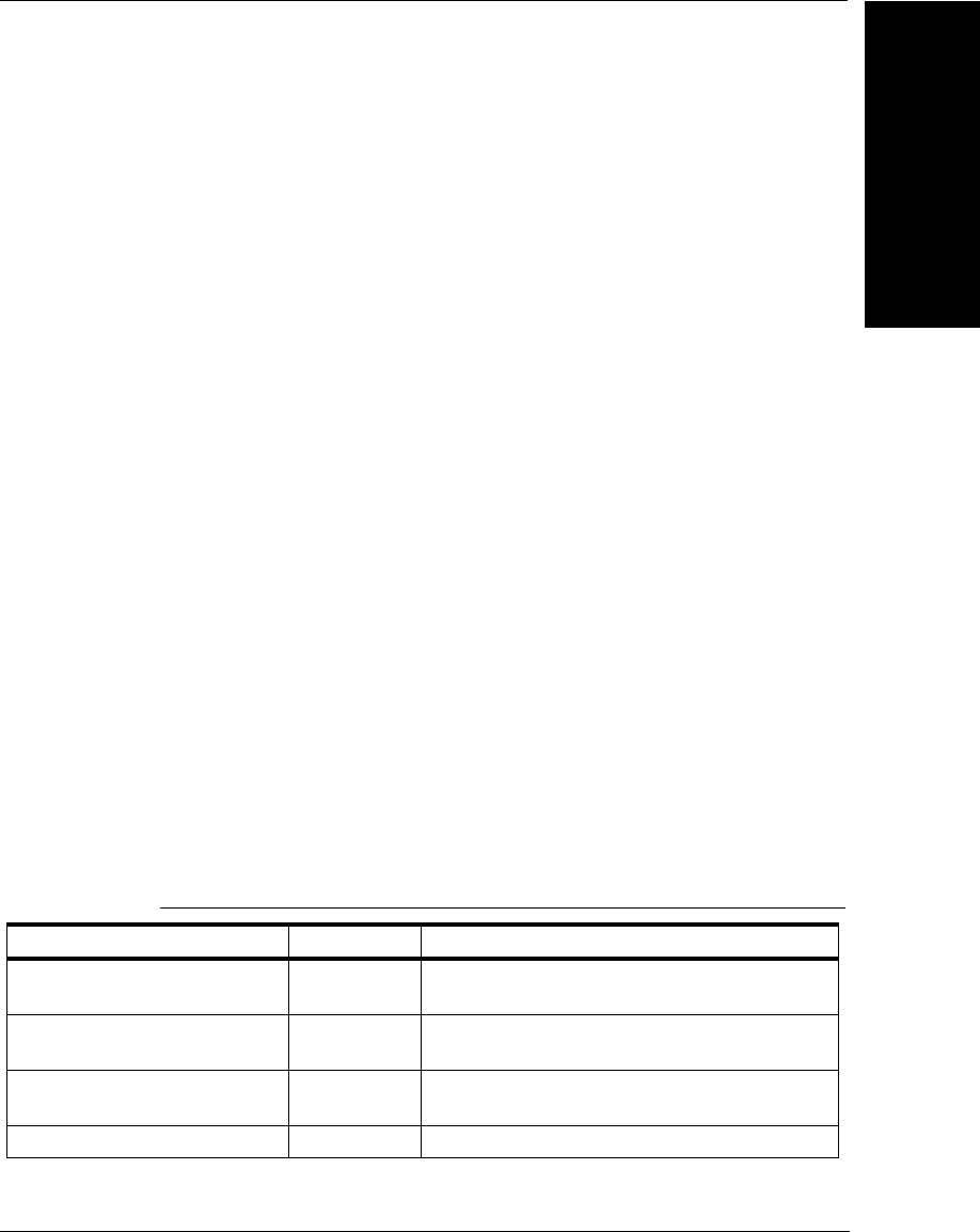
Runtime/Target Manager ActiveX Control
Legacy Controls
B
Visionscape Programmer’s Kit (VSKit) Manual B-65
– RUNMGR_E_NOBUFCTL if there is currently no Buffer Manager
control, and/or any of the Buffer Manager ZoomTo() method
return values
– E_FAIL on a general failure
About Results Upload Methods
Results are a set of datums on the target that are uploaded to the host at
the end of each inspection. Each inspection has its own set of results.
When the results are uploaded to the host, the data is stored in a table,
which includes the datum user name, symbolic name, GUID (type), and
value represented as a Variant. When results are activated for a particular
inspection, the control sends the ResultsUploadDone event, at which time
the caller must retrieve the data. Callers should simply retrieve the data
into their own memory structures and process the results later, either on a
separate thread or with a timer, in order to keep the event handler as fast
as possible.
In addition to this section, refer to the FrontRunner Visual Basic source
code that accompanied your Visionscape software for a useful
demonstration on using the Results Upload mechanisms. The
FrontRunner source code is installed as part of the VBKIT installer. Visual
Basic installation and example code are also provided in Chapter 2,
“Jobs, Steps and Datums”.
Events
Table B–28 lists, and this section describes, the events for the Runtime
Manager, Target Manager, or both.
TABLE B–28. Runtime/Target Manager Events
Name Control Description
HostDisplayActive RunMgr Sent when remote display active state
changes.
HostFreezeFailChange RunMgr Sent when freeze mode state for remote
display changes.
HostGraphicsEvent RunMgr Sent when remote display tool graphics state
changes.
ImageUploadDone RunMgr Sent when a new image is uploaded.

Appendix BLegacy Controls
B-66 Visionscape Programmer’s Kit (VSKit) Manual
ImageUploadDoneEx RunMgr Sent when a set of new images is uploaded
and the UseImageUploadDoneEx property is
True.
InspSelected RunMgr Sent when a new inspection is selected.
IOTransition Both Sent when a virtual I/O point has transitioned.
JobDownloaded RunMgr Sent when a job is downloaded to the device.
JobGoingToStart RunMgr Sent when an inspection in the job is about to
be started.
JobPostDownload TgtMgr Sent after the job has been downloaded
JobPreDownload RunMgr Sent when a new download has been initiated.
JobStarted RunMgr Sent when an inspection in the job is started.
JobStopped RunMgr Sent when an inspection in the job is stopped.
MouseDown RunMgr Standard stock event, but only fired when
mouse is clicked in the image. Coordinates
are in Runtime Manager control space.
MouseMove RunMgr Standard stock event, but only fired when
mouse is clicked in the image. Coordinates
are in Runtime Manager control space.
MouseUp RunMgr Standard stock event, but only fired when
mouse is clicked in the image. Coordinates
are in Runtime Manager control space.
ResultsUploadDone Both Sent when new results data has been
uploaded.
ResultsUploadDoneEx Both Sent when new results data has been
uploaded and the UseResultsUploadDoneEx
property is True.
SnapshotSelected RunMgr Sent when a new snapshot is selected.
StatusBarActive RunMgr Sent when Status Bar display state changes.
StringResultsUploadDo ne Both Sent when a new result string is available.
SystemConnected RunMgr Sent when target system is connected.
SystemDisconnected RunMgr Sent when target system is disconnected.
TABLE B–28. Runtime/Target Manager Events (continued)

Runtime/Target Manager ActiveX Control
Legacy Controls
B
Visionscape Programmer’s Kit (VSKit) Manual B-67
TargetDisplayActive RunMgr Sent when direct display's active state
changes.
TargetGraphicsEvent RunMgr Sent when direct display's tool graphics state
changes.
TargFreezeFailChange RunMgr Sent when freeze mode state for direct display
changes.
ToolbarActive RunMgr Sent when Toolbar is shown or hidden.
TABLE B–28. Runtime/Target Manager Events (continued)

Appendix BLegacy Controls
B-68 Visionscape Programmer’s Kit (VSKit) Manual
• void HostDisplayActive(boolean bOn);
This event is sent when the remote display is activated or
deactivated. The bOn value indicates the new state.
• void HostFreezeFailChange(short nMode);
This event is sent when the frozen display mode of the remote display
is changed. The nMode value indicates the new state:
– 0 — Display all images
– 1 — Display failed images only
– 2 — Freeze current image
– 3 — Freeze next failure
– 4 — Display last failure
• void HostGraphicsEvent(boolean bUp);
This event is sent when the tool graphics state for the remote display
changes. The bUp value indicates the new state.
• void ImageUploadDone(long inspectionno, long snapno);
This event is sent when a new image has been uploaded. The
inspectionno value is the index of the running inspection and the
snapno value is the index of the snapshot in the inspection.
• void ImageUploadDoneEx(long inspectionno, IAvpInspReport*
rptObj);
This event is sent when a new image or images are available and the
ImageUploadUseExEvent property is True. The report object
contains a collection of the images and runtime statistics.
• void InspSelected(long nInspIndex);
This event is sent when an inspection has been selected. The
nInspIndex value is the inspection index.

Runtime/Target Manager ActiveX Control
Legacy Controls
B
Visionscape Programmer’s Kit (VSKit) Manual B-69
• void IOTransition(long IONumber, boolean IOState); - TgtMgr
This event is sent when a given virtual I/O point has transitioned and
the IOEventEnable property is True.
• void JobDownloaded(VARIANT strJobFile);
This event is sent when a new job has been downloaded to the
system. The strJobFile VARIANT is a string VARIANT of the full path
of the job downloaded.
• void JobGoingToStart(long nInspIndex);
This event is sent when an inspection is about to be started on the
system. The nInspIndex value is the index of the inspection.
• void JobPreDownload();
This event is sent before a download is initiated to the target.
• void JobStarted(long nInspIndex);
This event is sent when an inspection is started on the system. The
nInspIndex value is the index of the started inspection.
• void JobStopped(long nInspIndex);
This event is sent when an inspection is stopped on the system. The
nInspIndex value is the index of the stopped inspection.
• void ResultsDisplayUp(boolean bUp);
This event is sent when the Results Display window is shown or
hidden. The bUp value indicates the display state.
• void ResultsUploadDone(long inspectionno); - TgtMgr
void ResultsUploadDone(long inspectionno, boolean
bAlreadyPopped); - RunMgr
This event is sent when the results for the specified inspection are
uploaded. The results are uploaded after each inspection and the
owner of the control will not get another event until this event handler
has completed. The user may then use the ResultsGetValue,
ResultsGetNames, and ResultsGetType API on these latest set of
results. When this event handler returns, the results are no longer

Appendix BLegacy Controls
B-70 Visionscape Programmer’s Kit (VSKit) Manual
valid and future calls to the Results API will provide erroneous data.
In essence, the retrieved Results are valid only for the duration of this
event handler. In the event handler, the caller should use the API to
retrieve the results into its own data structures and perform
processing on the results (e.g., drawing to the screen, dumping to file)
in separate threads or with a timer. The bAlreadyPopped boolean is a
legacy parameter and is always False.
• void ResultsUploadDoneEx(long inspIndex, IAvpInspReport* rptObj);
This event is sent when new results are available and the
ResultsUploadUseExEvent property is set to True. The report object
contains a collection of all the result data along with runtime statistics.
• void SnapshotSelected(long nSnapIndex);
This event is sent when a new snapshot has been selected. The
nSnapIndex is the index of the snapshot in the current inspection.
• void StatusBarActive(boolean bUp);
This event is sent when the Status bar is shown or hidden. The bUp
value indicates the display state.
• void StringResultsUploadDone(long inspNo, BSTR strData);
This event is sent when a new result string is available from the
specified inspection. The string is represented in strData, no further
calls need to be made on the control to get the data.
• void SystemConnected(BSTR strSystem);
This event is sent when the target system is connected. The
strSystem value is the string name of the target system.
• void SystemDisconnected();
This event is sent when the target system is disconnected.
• void TargetDisplayActive(boolean bOn);
This event is sent when the direct display state changes. The bOn
value indicates the direct display state.
• void TargetGraphicsEvent(boolean bUp);

Runtime/Target Manager ActiveX Control
Legacy Controls
B
Visionscape Programmer’s Kit (VSKit) Manual B-71
This event is sent when the direct display tool graphics state
changes. The bUp value indicates the state.
• void TargFreezeFailChange(short nMode);
This event is sent when the frozen display mode of the direct display
is changed. The nMode value indicates the new state:
– 0 — Display all images
– 1 — Display failed images only
– 2 — Freeze current image
– 3 — Freeze next failure
– 4 — Display last failure
• void ToolbarActive(boolean bUp);
This event is sent when the Toolbar is shown or hidden. The bUp
value indicates the new state.
Error Codes
Table B–29 lists Runtime/Target error codes.
TABLE B–29. Runtime/Target Error Codes
Name Numeric Value
S_OK 0h
E_FAIL 4005h
E_OUTOFMEMORY 000Eh
RUNMGR_E_NOCONNECT 400h
RUNMGR_E_JOBNOTRUNNING 401h
RUNMGR_E_JOBISRUNNING 402h
RUNMGR_E_BADINSPINDEX 403h
RUNMGR_E_NOBUFVIEW 404h
RUNMGR_E_NOBUFCTL 405h
RUNMGR_E_NOJOB 406h
TARGMGR_E_NOCONNECT 280h

Appendix BLegacy Controls
B-72 Visionscape Programmer’s Kit (VSKit) Manual
TARGMGR_E_NOSNAPS 281h
TARGMGR_E_NOINSPS 282h
TARGMGR_E_NORESULTS 283h
TARGMGR_E_NORESULTSOFID 284h
TARGMGR_E_BADINSPINDEX 285h
TARGMGR_E_JOBNOTRUNNING 286h
TARGMGR_E_JOBISRUNNING 287h
TARGMGR_E_RESUPLDNOTSTARTED 288h
TARGMGR_E_RESUPLDSTARTED 289h
TARGMGR_E_NOTTARGETSTEP 28Ah
TARGMGR_E_ILLEGALVARIANT 28Bh
TARGMGR_E_IMGUPLDNOTSTARTED 28Ch
TARGMGR_E_NORPCCONNECT 28Dh
TARGMGR_E_DATUMNOTOFOUND 28Eh
TARGMGR_E_NOVIRUTALIO 28FH
TARGMGR_E_BADSNAPINDEX 290H
TARGMGR_E_BADSOCKTAGREAD 291H
TARGMGR_E_BADSOCKDATAREAD 292H
TARGMGR_E_NOTIFFSAVE 293H
TARGMGR_E_SOCKTIMEOUT 294H
TARGMGR_E_NORESULTSPOPPED 295H
TARGMGR_E_NORESULTDATA 296H
TARGMGR_E_BADDATUMTYPE 297H
TARGMGR_E_NOPERLMODROOT 298H
TARGMGR_E_NOPERLSCRIPTS 299H
TARGMGR_E_NOMAKEPERLDRV 29AH
TARGMGR_E_FTPXFERFAILED 29BH
TARGMGR_E_TJOBPERLCMDFAILED 29CH
TARGMGR_E_FSPECNOFILES 29DH
TARGMGR_E_TJOBFILESPECCMDFAILED 29EH
TARGMGR_E_NOTINDNLOAD 29FH
TARGMGR_E_NOTHREAD 2A0H
TABLE B–29. Runtime/Target Error Codes (continued)

Runtime/Target Manager ActiveX Control
Legacy Controls
B
Visionscape Programmer’s Kit (VSKit) Manual B-73
TARGMGR_E_NOFTPCONNECT 2A1H
TARGMGR_E_NOHOSTLOOKUP 2A2H
TARGMGR_E_REENTRANCY 2A3H
TARGMGR_E_NODNLOADCONNECT 2A4H
TARGMGR_E_FTPFAILED 2A5H
TARGMGR_E_DNERRINIT 2A6H
TARGMGR_E_DNERRTARGCLEANUP 2A7H
TARGMGR_E_DNERRSTREAMING 2A8H
TARGMGR_E_DNERRPREPARERUN 2A9H
TARGMGR_E_DNERRCONNECTING 2AAH
TARGMGR_E_DNERRDISCONNECTING 2ABH
TARGMGR_E_DNERRNOTARGMEMSTATS 2ACH
TARGMGR_E_DNERRSPACEBANK0 2ADH
TARGMGR_E_DNERRSPACEBANK1 2AEH
TABLE B–29. Runtime/Target Error Codes (continued)

Appendix BLegacy Controls
B-74 Visionscape Programmer’s Kit (VSKit) Manual

Visionscape Programmer’s Kit (VSKit) Manual C-1
C
Advanced Datums
C
APPENDIX C Advanced Datums
In Chapter 2, we discussed how to work with Steps and Datums. In that
chapter, we stuck to covering the generic Step and Datum objects. There
are several Datum types provided by Visionscape, however, that provide
advanced capabilities or result information. In this chapter we’ll discuss
some of those datums and what their capabilities are.
The DMR Tool’s VerifyDetails Datum
The Data Matrix tool can read Data Matrix codes, but it’s also capable of
verifying the print quality of the Data Matrix. This print quality check is
referred to as Verification. The Data Matrix tool provides a special output
datum, VerifyResultsDm, that holds the verification data. The contents of
this datum are a bit harder to explain than most, so we've provided a
special section to cover it. To work with this datum in Visual Basic, add
the following reference to your project:
+Visionscape Steps: DataMatrix
The value property of the VerifyResultsDm will return you a one
dimensional array that contains all of the verification details for one Data
Matrix. The size of this array is fixed, but its contents are determined by
the type of verification you selected in the Data Matrix tool’s “Print
Verification” datum. So, the array has an entry for every possible
verification value from each of the verification types, but you need to
understand that if you choose “ISO” verification, only the entries that are
relevant to ISO verification are filled in. The same is True for DPM,

Appendix CAdvanced Datums
C-2 Visionscape Programmer’s Kit (VSKit) Manual
ISOAIM, etc. Table C–1 explains the meaning of each entry in the array
returned by the value property, and also lists which verification types will
update each entry.
TABLE C–1. Entry Meanings
Index Data Description AIM ISO IAQG DPM ISOAIM
0Verification Type (string) XXXXX
1Verification Status XXXXX
2Overall Grade XXXXX
3Symbol Height XXXXX
4Symbol Angle XXXXX
5Symbol Width XXXXX
6 Cell Size Result X X X X
7 Value of the “Contrast Report” datum in
the DMR tool
XX XX
8 Contrast Grade X X X X
9 Axial non-uniformity grade X X X X
10 Print Growth X X X X X
11 Print Growth Y X X X X
12 Print Growth Grade X X
13 Error Bits Grade X X X X
14 Grid non-uniformity grade X X
15 Grid non-uniformity value X X
16 Fixed Pattern Damage Grade X X
17 Modulation Grade X X
18 Reference Decode Grade X X
19 Quality 20 Z X X
20 Dot Size Grade X
21 Dot Size 1 X
22 Dot Size 2 X
23 Dot Center Grade X
24 Dot Center 1 X
25 Dot Center 2 X
26 Distortion Angle Grade X X
27 Distortion Angle value X X
28 Cell Fill X X

The DMR Tool’s VerifyDetails Datum
Advanced Datums
C
Visionscape Programmer’s Kit (VSKit) Manual C-3
29 Cell Fill Y X
30 Cell Size Grade X
31 Center Offset Grade X
32 Center Offset value X
33 Size Offset Grade X
34 Size Offset value X
35 Cell Modulation Grade X
36 Cell Modulation On X
37 Cell Modulation Off X
38 Border Match Grade X
39 Border Match value X
40 Ovality Grade X
41 Ovality value X
42Value of the “Calibration Enabled” datumXXXXX
43ECC Level Result XXXXX
44 Value of the “Verification Status Upper
Threshold” datum
XXX X
45 Value of the “Verification Status Lower
Upper Threshold” datum
XXX X
46Value of the “Contrast Report” datumXXXXX
47Value of the “Cell Unit Report” datumXXXXX
48Value of the “Aperture” datum XXXXX
49Value of the “Target Contrast” datumXXXXX
50Value of the “Contrast Max” datum XXXXX
51Value of the “Contrast Min” datum XXXXX
52Value of the “Calibration Cell Unit” datumXXXXX
53 Axial non-uniformity X X X X
54 Custom Verification enabled (bit pattern) X
55 Value of the “Cell Size VerStat
UpThresh” datum
X
56 Value of the “Cell Size VerStat
LoThresh” datum
X
57 Value of the “Center Offset VerStat
UpThresh” datum
X
TABLE C–1. Entry Meanings (continued)
Index Data Description AIM ISO IAQG DPM ISOAIM

Appendix CAdvanced Datums
C-4 Visionscape Programmer’s Kit (VSKit) Manual
58 Value of the “Center Offset VerStat
LoThresh” datum
X
59 Value of the “Size Offset VerStat
UpThresh” datum
X
60 Value of the “Size Offset VerStat
LoThresh” datum
X
61 Value of the “Cell Modulation VerStat
UpThresh” datum
X
62 Value of the “Cell Modulation VerStat
LoThresh” datum
X
63 Value of the “Border Match VerStat
UpThresh” datum
X
64 Value of the “Border Match VerStat
LoThresh” datum
X
65 Value of the “Symbol Contrast VerStat
UpThresh” datum
X
66 Value of the “Symbol Contrast VerStat
LoThresh” datum
X
67 Value of the “Axial Nonuniformity VerStat
UpThresh” datum
X
68 Value of the “Axial Nonuniformity VerStat
LoThresh” datum
X
69 Value of the “Print Growth VerStat
UpThresh” datum
X
70 Value of the “Print Growth VerStat
LoThresh” datum
X
71 Value of the “Unused Error Correction
VerStat UpThresh” datum
X
72 Value of the “Unused Error Correction
VerStat LoThresh” datum
X
73 Value of the “Angle of Distortion VerStat
UpThresh” datum
X
74 Value of the “Angle of Distortion VerStat
LoThresh” datum
X
75 Unused Error Correction X X X X
TABLE C–1. Entry Meanings (continued)
Index Data Description AIM ISO IAQG DPM ISOAIM
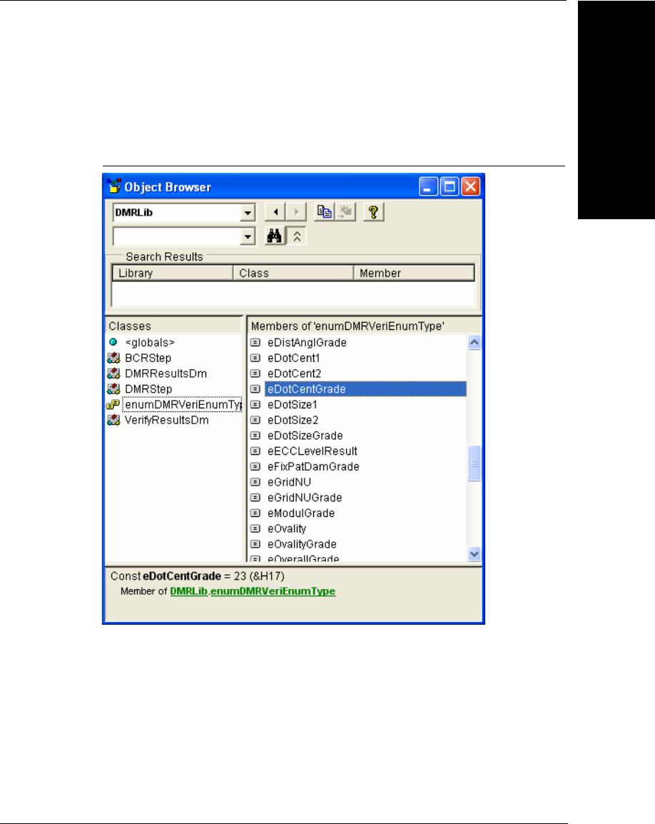
The DMR Tool’s VerifyDetails Datum
Advanced Datums
C
Visionscape Programmer’s Kit (VSKit) Manual C-5
The enumerated type enumDMRVeriEnumType is also provided to make
it easier to query elements of the array. The object browser may be used
to look at the available enumeration values, as shown in Figure C–1.
FIGURE C–1. Available Enumeration Values
By adding a helper routine to your code like Dmrenum shown below, a list
of available enumeration values is presented to the programmer for
selection, as shown in Figure C–2.
Public Function Dmrenum(eType As enumDMRVeriEnumType) As Variant
Dmrenum = eType
End Function
…
Dim vVarRes As Variant
…
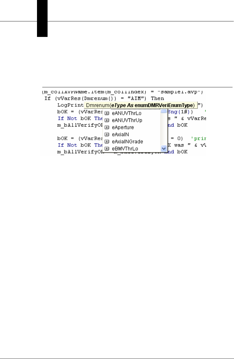
Appendix CAdvanced Datums
C-6 Visionscape Programmer’s Kit (VSKit) Manual
vVarRes = result.Value
If (vVarRes(Dmrenum(eVerType)) = "AIM") Then
…
FIGURE C–2.
Some useful translation routines are listed below:
Public Function GetContrastReportString(Value As Long) As String
Const CONTRAST_UNCALIBRATED = 0
Const CONTRAST_SELF_CALIBRATED = 1
Const CONTRAST_REFLECTANCE_CALIBRATED = 2
Select Case Value
Case CONTRAST_UNCALIBRATED
GetContrastReportString = "UN_Cal"
Case CONTRAST_SELF_CALIBRATED
GetContrastReportString = "SELF_Cal"
Case CONTRAST_REFLECTANCE_CALIBRATED
GetContrastReportString = "REFL_Cal"
Case Else
GetContrastReportString = "???"
End Select
End Function
Public Function GetStatusString(Value As Long) As String
Const LEARNING_STATUS = 0
Const GOOD_STATUS = 1
Const FAIR_STATUS = 2
Const POOR_STATUS = 3
Select Case Value
Case LEARNING_STATUS
GetStatusString = "No Verify - Learning"
Case GOOD_STATUS
GetStatusString = "Good"
Case FAIR_STATUS

Changing the OCV Tool Layout String Using the “LayoutInfo” Datum
Advanced Datums
C
Visionscape Programmer’s Kit (VSKit) Manual C-7
GetStatusString = "Fair"
Case POOR_STATUS
GetStatusString = "Poor"
Case Else
GetStatusString = "Verification Error Code " & Value
End Select
End Function
Public Function GetCellUnitReportString(Value As Long) As String
Const CELL_UNIT_IN_PIXELS = 0
Const CELL_UNIT_IN_MILS = 1 '/* 1/1000th inch */
Select Case Value
Case CELL_UNIT_IN_PIXELS
GetCellUnitReportString = "PIXELS"
Case CELL_UNIT_IN_MILS
GetCellUnitReportString = "MILS"
Case Else
GetCellUnitReportString = "???"
End Select
End Function
Public Function GetApertureString(Value As Long) As String
Select Case Value
Case 0
GetApertureString = "AUTO"
Case Else
GetApertureString = Value
End Select
End Function
Note: All elements in the VerifyDetails array may be obtained individually
from the discrete datums that were placed in the VerifyDetails array.
Changing the OCV Tool Layout String Using the
“LayoutInfo” Datum
When using the OCVFont tool in Visionscape, the user would typically
retrain the tool via the UI when ever the inspected string changes. It is
possible however to change the trained code, or layout string, via your VB
code. This can be done by accessing the “LayoutInfo” datum of the
OCVFont Tool. There are several restrictions that apply however:

Appendix CAdvanced Datums
C-8 Visionscape Programmer’s Kit (VSKit) Manual
1. You can only change the layout string of the OCVFont tool. You
CANNOT change the layout string of the OCV Fontless Tool or the
OCV Runtime Tool.
2. You cannot change the layout string while the inspection is running.
All inspections must be stopped before you attempt to change the
string.
3. The OCVFont Tool must be manually trained by hand at least once.
This tells the tool how many characters are in the string, and what
their positions are. Once the tool has this information, you can
change the string programmatically.
4. The number of characters in the layout string must stay the same. In
other words, if you’ve trained the tool on a 10 character string, then
you must always specify a 10 character string when changing the
layout.
5. Before changing the string, you must either have a Setup Manager
control connected, or you must explicitly take control of the vision
hardware by using the VisionSystem Step’s AddTargetUsage and
ReleaseTargetUsage methods. This is demonstrated in our upcoming
sample code.
Follow these steps to change the layout string of an OCV Font tool:
1. Add the following reference to your Job:
+Visionscape Steps: OCV Tool
2. Locate the OCV Font tool in your Job.
3. Extract the OCV Tool’s current layout information.
4. Make sure the length of the current string matches the length of the
new string.
5. Update the characters in the layout to match your new string.
6. Set the updated layout information back into the OCV Font Step.
Following is an example function that demonstrates how you should
update the layout of an OCV Font step. This function takes in the string
that will be used to update the layout, and then performs each of the steps
we listed above:

Changing the OCV Tool Layout String Using the “LayoutInfo” Datum
Advanced Datums
C
Visionscape Programmer’s Kit (VSKit) Manual C-9
Private Sub ChangeLayout(strNewString As String)
Dim OcvStep As Step, vLayoutInfo As Variant
Dim i As Integer, j As Integer, NumChars As Long
'find the 1st OCV tool under our Job
Set OcvStep = m_Job.Find("Step.OCVFontTool", FIND_BY_TYPE)
'get the current layout information,
' this will return a variant array
vLayoutInfo = OcvStep.Datum("LayInfo").Value
NumChars = UBound(vLayoutInfo) + 1 'the first dimension of
‘this array = number of characters
'verify the size of the existing string = size of new string
If NumChars = Len(strNewString) Then
Dim font As OCVFont, bCharInLib As Boolean
Dim thisChar As String, SymbolID As Long
Dim FontChar As String, SymWidth As Long
Dim SymHeight As Long, nNumFontSymbols As Long
'call our util function to get the current font library
Set font = GetFontToolTrainFont(OcvStep)
'get the number of trained symbols in our font
nNumFontSymbols = font.GetNumSymbols
'update the symbols in the layout
For i = 0 To NumChars - 1
bCharInLib = False
'extract the next character from the input string
thisChar = Mid(strNewString, i + 1, 1)
' Find new char in the font library and update the layout info
For j = 0 To nNumFontSymbols - 1
SymbolID = font.GetSymbolIDByIndex(j)
FontChar = font.GetSymbolName(SymbolID)
If thisChar = FontChar Then
SymWidth = font.GetSymbolWidth(SymbolID)
SymHeight = font.GetSymbolHeight(SymbolID)
vLayoutInfo(i, 0) = SymbolID
vLayoutInfo(i, 4) = SymWidth
vLayoutInfo(i, 5) = SymHeight
bCharInLib = True
End If
Next j
If Not bCharInLib Then
' Character was not found in library
'post error message
MsgBox "Couldn't find character in Font library, Layout Not Updated"

Appendix CAdvanced Datums
C-10 Visionscape Programmer’s Kit (VSKit) Manual
Exit Sub
End If
Next i
'update the OCV step with our new layout
mVS.AddTargetUsage 'NOTE: This is only required if you are not connected to SetupManager
OcvStep.Datum("LayInfo").Value = vLayoutInfo
mVS.ReleaseTargetUsage 'NOTE: This is only required if you are not connected to
SetupManager
Else
MsgBox "The specified string is not the same size as the current layout string", _
vbExclamation, "Layout Change Rejected"
End If
End Sub
Public Function GetFontToolTrainFont(thisOCVFontTool As OCVFontTool) As OCVFont
Dim ILayoutStep As LayoutStep
Dim hc As New AvpHandleConverter, hOCVFont As Long
Dim vVal As Variant
'try to get the current scale font
hOCVFont = thisOCVFontTool.GetScaleFontHandle
If (hOCVFont = 0) Then
'no scale font, so make sure the font is selected..
'find Layout Step, this is where the font is selected
Set ILayoutStep = thisOCVFontTool.Find("LayoutStep1", FIND_BY_SYMNAME)
'get the selected font
vVal = ILayoutStep.Datum("SelFont").Value
'select the font into the layout step
If UBound(vVal) > 0 Then
thisOCVFontTool.SelectTrainFont vVal(vVal(0) + 1)
Else
thisOCVFontTool.SelectTrainFont 0
End If
'now query the GetTrainFontHandle method,
' this returns a handle to a font lib
hOCVFont = thisOCVFontTool.GetTrainFontHandle
End If
'convert the handle to an actual font object
Set GetFontToolTrainFont = hc.AvpObject(hOCVFont)
End Function
Changing the Camera Selection with the CamDefDm Datum
The CamDefDm datum is provided to allow you to query the list of
currently installed Camera Definition files, and to allow you to select a
different camera programmatically. This datum belongs to the

Changing the Camera Selection with the CamDefDm Datum
Advanced Datums
C
Visionscape Programmer’s Kit (VSKit) Manual C-11
VisionSystemStep, and has the symbolic name “CamDefFile1”. You can
access the CamDefDm of your VisionSystem step with code that looks
like this (m_VS is a reference to a Vision System Step):
Dim camdef As CamDefDm
Set camdef = m_VS.Datum("CamDefFile1")
Now that you have a reference to the CamDefDm, you can change the
selected camera type for any of the device’s camera channels by using
the ChannelSelect method:
Sub ChannelSelect(nChannel As Long, bszCameraName As String, BufPoolCount As
Long)
nChannel = 0 based index of the channel whose
camera definition you wish to change.
bszCameraName = String that contains the name of
the camera type you wish to change to.
BufPoolCount = Number of image buffers that should
be allocated for this camera type. Pass in 0 if you
want the framework to figure out the ideal number
of buffers for you.
Example:
‘ Set channel 1 to use the STC-A152A camera
camdef.ChannelSelect 0, "STC-A152A 1352x1040", 0
‘ Set channel 2 to use the CM4001 camera
camdef.ChannelSelect 1, "CM4001 768x572", 0
Note: Only Software Systems support multiple resolutions, as illustrated
in our example above.
The CamDefDm object also provides the following useful methods and
properties.
• Function CamFileForCamera(bszCamera As String) As String
Returns the Camera Definition file for a specific camera by name.
• Function DigTypeForCamera(bszCamera As String) As Long

Appendix CAdvanced Datums
C-12 Visionscape Programmer’s Kit (VSKit) Manual
Returns the digitizer type in a CamDef file for a specific camera by
name.
• Function ImageHeightForCamera(bszCamera As String) As Long
Returns the image height of the specified camera type.
• Function ImageWidthForCamera(bszCamera As String) As Long
Returns the image width of the specified camera type.
• Function LastSavedCamDefWasFound(nChannel As Long) As Boolean
If you load a job from disk, and the CamDef file for the specified
channel is not installed, this will return false. Returns true if it is
installed.
• Function LastSavedCamDef(nChannel As Long) As String
If you load a job from disk, and the CamDef file for the specified
channel is not installed, you can use this method to retrieve the name
of the CamDef file that was last saved for this channel.

Visionscape Programmer’s Kit (VSKit) Manual D-1
D
Installed Sample
Applications
D
APPENDIX D Installed Sample
Applications
The AutoVISION/Visionscape installer comes with a collection of VB
sample applications. This appendix describes how to install the samples,
and provides a brief description of each one.
Installing the Samples
Locate the SetupAutoVISION.exe installer file on the Microscan Tools
Drive or in the Download Center at www.microscan.com.
AppRunner Source Code
We provide the complete source code for the Visionscape AppRunner
application. If you find that AppRunner provides almost all of the
functionality that you require, but you need just a little bit more, then you
can simply modify the application to do whatever you need. You can also
use the sources as example code, to learn how AppRunner accomplishes
tasks.

Appendix DInstalled Sample Applications
D-2 Visionscape Programmer’s Kit (VSKit) Manual
VSRUNKIT Sample
Adv02_apprunnerlite
You’ll find this sample under the VsKit Samples\Extras\Adv02_VsRunKit
folder. The apprunnerlite sample demonstrates how to use the
VsRunView control in a complete, but simple, user interface for
monitoring smart cameras and loading and running jobs on Visionscape
GigE Cameras. As the name implies, this application is intended to be a
stripped down version of AppRunner, without a lot of the bells and
whistles, so it is easier to understand. It demonstrates how to load,
download, and run AVP files, on any Visionscape device type. This
application can be used as a starting point for your own custom user
interfaces.
VSKIT Samples
The remaining samples all demonstrate how to create simple user
interfaces using nothing but the controls in the VSKIT OCX. These
samples are meant to illustrate concepts rather than to act as complete
interfaces. A quick description of each sample follows.
Ex01_Simple
This sample demonstrates how to create a simple monitoring application
using the VsDeviceDropdown and VsFilmStrip controls. By selecting a
device in the dropdown, the application will automatically start displaying
images from that device in the filmstrip control. A VsFileUtilities control is
also added to the project, which allows you to select GigE Cameras as
well as smart cameras. Whenever you select a device, you will be asked
to specify the AVP file that you want to run on that device. Then, the AVP
will be loaded, downloaded and started. When you look at this sample
application, you will see that it contains very little code.
Ex02_Control
This sample is more involved, and demonstrates taking control of a smart
camera so that you can start or stop its inspections and change the
running AVP. Getting and setting IO values is also demonstrated. Refer to
the comments at the top of frmMain.frm for a complete description.

Extras
Installed Sample
Applications
D
Visionscape Programmer’s Kit (VSKit) Manual D-3
Ex03_Monitor
This sample describes how to monitor any device, plus the following
functionality:
• Displays images in a running filmstrip using the VsFilmstrip control.
• Graphs timing data using the VsDataCanvas control
• Displays uploaded results using the VsReport control.
• Displays a range of io values using the VsIOButtons control.
Ex04_Editor
This sample uses the VsView control to provide both runtime and setup
capabilities. This is the same control used by FrontRunner. Also, this
example demonstrates how to tie a toolbar into the capabilities of VsView.
Refer to the comments at the top of frmMain.frm for a complete
description.
Ex05_CreateAndControl
This sample is similar to Ex03_Monitor, but rather than loading an AVP
from disk, it demonstrates how an AVP can be created programatically.
Refer to the comments at the top of frmMain.frm for a complete
description.
Extras
Adv01_Engine
This sample is for Visionscape GigE Cameras only. It demonstrates how
you can load, connect and run an AVP on a Visionscape device in one
process, and then monitor the images and results from a separate
process. The VB application handles loading, connecting and starting the
AVP; if you then connect to the device via FrontRunner, you will see that it
will start monitoring the images and results, as if you had connected to a
running smart camera. The application also places an icon in the
Windows System Tray which provides an indication of the current
run/stop state of the inspections.

Appendix DInstalled Sample Applications
D-4 Visionscape Programmer’s Kit (VSKit) Manual
