Getting Started With The Verification Monitoring Interface (VMI) Vmigettingstartedguide
2016-08-18
: Microscan Vmigettingstartedguide vmigettingstartedguide center
Open the PDF directly: View PDF ![]() .
.
Page Count: 68
- Getting Started with the Verification Monitoring Interface (VMI)
- Contents
- PREFACE Welcome
- CHAPTER 1 Hardware and Software Installation
- CHAPTER 2 The VMI Interface
- CHAPTER 3 Starting VMI and Creating Your First Job
- CHAPTER 4 Runtime and Job Monitoring

Getting Started with the
Verification Monitoring Interface
(VMI)
84-9111022-02 Rev C
v1.0.2, March 2015
Copyright ©2015
Microscan Systems, Inc.
Tel: +1.425.226.5700 / 800.762.1149
Fax: +1.425.226.8250
All rights reserved. The information contained herein is proprietary and is provided solely for the purpose of
allowing customers to operate and/or service Microscan manufactured equipment and is not to be released,
reproduced, or used for any other purpose without written permission of Microscan.
Throughout this manual, trademarked names might be used. We state herein that we are using the names to the
benefit of the trademark owner, with no intention of infringement.
Disclaimer
The information and specifications described in this manual are subject to change without notice.
Latest Manual Version
For the latest version of this manual, see the Download Center on our web site at:
www.microscan.com.
Technical Support
For technical support, e-mail: helpdesk@microscan.com.
Warranty
For current warranty information, see: www.microscan.com/warranty.
Microscan Systems, Inc.
United States Corporate Headquarters
+1.425.226.5700 / 800.762.1149
United States Northeast Technology Center
+1.603.598.8400 / 800.468.9503
European Headquarters
+31.172.423360
Asia Pacific Headquarters
+65.6846.1214

Getting Started with VMI iii
Contents
PREFACE Welcome v
Purpose of this Guide v
What Is VMI? v
How Is VMI Different from Standard AutoVISION? vi
CHAPTER 1 Hardware and Software Installation 1-1
What’s in the Box 1-2
Mounting and Installing Hardware 1-3
Application Tips 1-5
PC Requirements and Settings 1-6
Modifications Required when Using VMI with a Panel PC 1-7
VMI Installation 1-8
Launching VMI 1-9
CHAPTER 2 The VMI Interface 2-1
The VMI User Interface 2-2
Similarities between VMI and AutoVISION Setup 2-2
Differences between VMI and AutoVISION Setup 2-6
User Access Levels 2-7
CHAPTER 3 Starting VMI and Creating Your First Job 3-1
Starting VMI for the First Time 3-2
Select a Device 3-2
Create a New Job 3-4
Adjust the Image 3-5
Edit the Job 3-7
Save the Job 3-24
Open a Job 3-25
CHAPTER 4 Runtime and Job Monitoring 4-1
VMI Startup Options 4-2
VMI Runtime 4-3
Example VMI Startup Process 4-14

Contents
iv Getting Started with VMI

Getting Started with VMI v
Preface
PREFACE Welcome
Purpose of this Guide
This guide describes how to use Microscan’s Verification Monitoring Interface (VMI) to
configure and run symbol quality verification applications.
What Is VMI?
The Microscan Verification Monitoring Interface (VMI) Solution provides inline verification
grading of 1D barcodes such as ITF-14 on carton board (corrugated cardboard) in a
production environment. VMI processing provides a data set that can be used to evaluate
print quality based on an ISO grade, to use statistical trending, and to enable printer
condition monitoring. An example use case would be the monitoring of print quality to
detect a potential clog in a print head. This leads to cost savings for the user because
instead of purging the print heads every several print runs, the print heads can be purged
only when needed. When a barcode has a grade below a minimum specified value, VMI
also provides an output that can be used as a reject signal.

Preface
vi Getting Started with VMI
How Is VMI Different from Standard AutoVISION?
The VMI plug-in will modify the standard look and behavior of AutoVISION in the following ways:
•Security: Adds four user access levels with password protection to the interface. A
password must be entered to exit the run screen and to enter edit mode, load jobs,
modify parameters, etc. The security features in VMI are enabled by default and
cannot be disabled, whereas they are optional in AutoVISION. Refer to the Security
Settings section for more information.
•Startup Behavior: VMI will always automatically connect to the device that you
selected the last time you ran the software. It will also automatically load the last job that
you were using and download it to the camera, and then put the camera into run mode.
•Verification-Specific Run View: Replaces the standard Run view with a screen that
provides Verification specific feedback and logging capabilities.
•New Job: When creating a new job in VMI, you don’t start with a blank job as in
standard AutoVISION; you start with a fully functioning default verification inspection.
This job can be modified from its defaults, but the user does not have to understand
how to build a verification inspection – it is created automatically.
•
Load Job Validation:
VMI requires valid verification jobs. When loading a job in VMI, the
job will be scanned to ensure that it is based on the VMI job template. A standard
AutoVISION job will be rejected, even if it has a verification tool in it.
•
Settings Page:
A special settings page is added to the Edit view to encapsulate all of the
major Verification settings in once place. Refer to the Settings Page area for more information.

Getting Started with VMI 1-1
1
Hardware and
Software Installation
1
CHAPTER 1 Hardware and Software
Installation
This section describes how to install VMI Software and the hardware
required for VMI applications.
Chapter 1Hardware and Software Installation
1-2 Getting Started with VMI
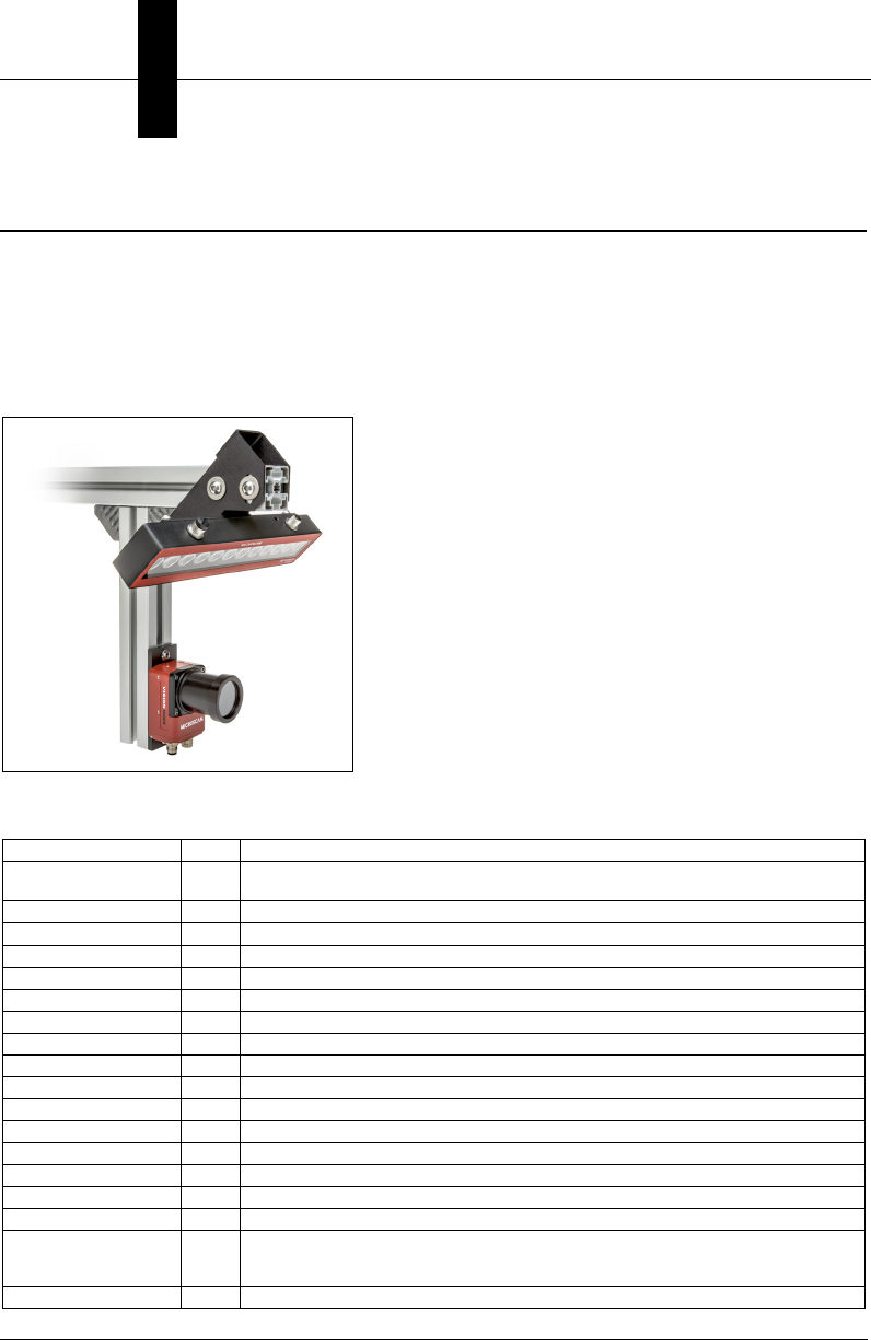
What’s in the Box
VMI (P/N
SLN-0000018
) is intended for use with a modified version of Microscan’s
Large
Linear Verification Kit
(P/N
SLN-0000006
), an example of which is shown below. For detailed
mounting instructions, refer to the Large Linear Verification Kit Quick Start Guide, entitled Using
the Large Linear Verification Kit. The guide is located in the
Download Center
at
www.microscan.com
. Bracket assembly instructions can also be found in the Microscan
Download Center.
Required Hardware
Part Number Qty. Description
GMV-6800-1038G 1 Vision HAWK C-Mount Smart Camera, WUXGA Mono,
AutoVISION+Visionscape+Verification/OCV+VMI
NER-011660301G 1 NERLITE Smart Series MAX 300, Red, Wide, M12 connector
97-000006-01 1 DSP100-24 Power Supply
61-000163-02 1 Ethernet Cable
61-000167-02 1 Camera Power / Signal Cable
61-000186-01 1 Illuminator Power / Signal Cable
User-Supplied 1 Dedicated PC
User-Supplied 1 Ethernet Switch
User-Supplied 1 USB Keyboard
User-Supplied 1 USB Mouse
User-Supplied 1 Ethernet Cable, PC to Ethernet Switch
User-Supplied 1 Power Cable, PC to DSP100-24 Power Supply
User-Supplied 1 Object Detector / Trigger
98-000259-01 1 Lens
98-000218-01 1 Lens Protection Housing
98-000268-01 1 Bracket
98-000265-01 1
Calibration Card with NIST-Traceable Serial Number and Reflectance Data (not
included in SLN-0000018 kits but available for purchase; Measurement
Certificate included with purchase of NIST-Traceable Calibration Card)
98-000265-02 1 Calibration Card (included in all verification kits)
To achieve the most uniform lighting possible in an
image, the light should be as far away from the region
of interest as possible while maintaining a 45 degree
angle and achieving adequate illumination.
For large 1D symbols this may require the light to
be on the shorter extrusion and the camera on the
longer extrusion as shown in Configuration 2 of the
Large Linear Verification Kit Quick Start Guide, entitled
Using the Large Linear Verification Kit.
Note:
If you already have the necessary hardware
and do not need to order the SLN-0000018 kit, you
will need to purchase an AutoVISION Verification
and VMI License Upgrade (P/N 98-000217-05).
Mounting and Installing Hardware
Hardware and
Software Installation
1
Getting Started with VMI 1-3
Mounting and Installing Hardware
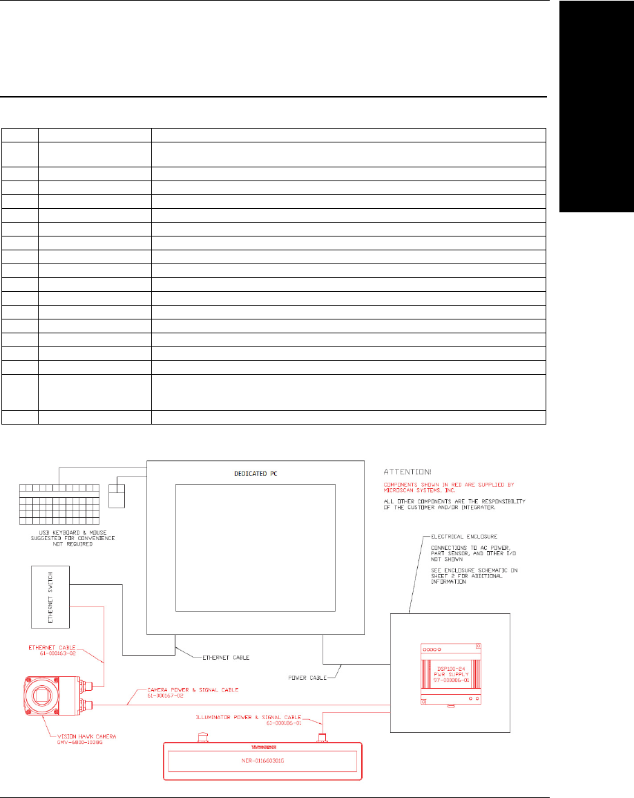
Hardware Configuration
Note: Components shown in red are supplied by Microscan. Components shown in black must be supplied by
the integrator or end-user.
Item Part Number Description
1GMV-6800-1038G Vision HAWK C-Mount Smart Camera, WUXGA Mono, AutoVISION
+Visionscape+Verification/OCV+VMI
2NER-011660301G NERLITE Smart Series MAX 300, Red, Wide, M12 connector
397-000006-01 DSP100-24 Power Supply
461-000163-02 Ethernet Cable
561-000167-02 Camera Power / Signal Cable
661-000186-01 Illuminator Power / Signal Cable
7User-Supplied Dedicated PC
8User-Supplied Ethernet Switch
9User-Supplied USB Keyboard
10 User-Supplied USB Mouse
11 User-Supplied Ethernet Cable, PC to Ethernet Switch
12 User-Supplied Power Cable, PC to DSP100-24 Power Supply
13 User-Supplied Object Detector / Trigger (required for application but not shown below)
14 98-000259-01 Lens
15 98-000218-01 Lens Protection Housing
16 98-000268-01 Bracket
17 98-000265-01
Calibration Card with NIST-Traceable Serial Number and Reflectance Data (not
included in SLN-0000018 kits but available for purchase; Measurement
Certificate included with purchase of NIST-Traceable Calibration Card)
18 98-000265-02 Calibration Card (included in all verification kits)
1
2
3
4
56
7
8
9
10
11 12
Chapter 1Hardware and Software Installation
1-4 Getting Started with VMI
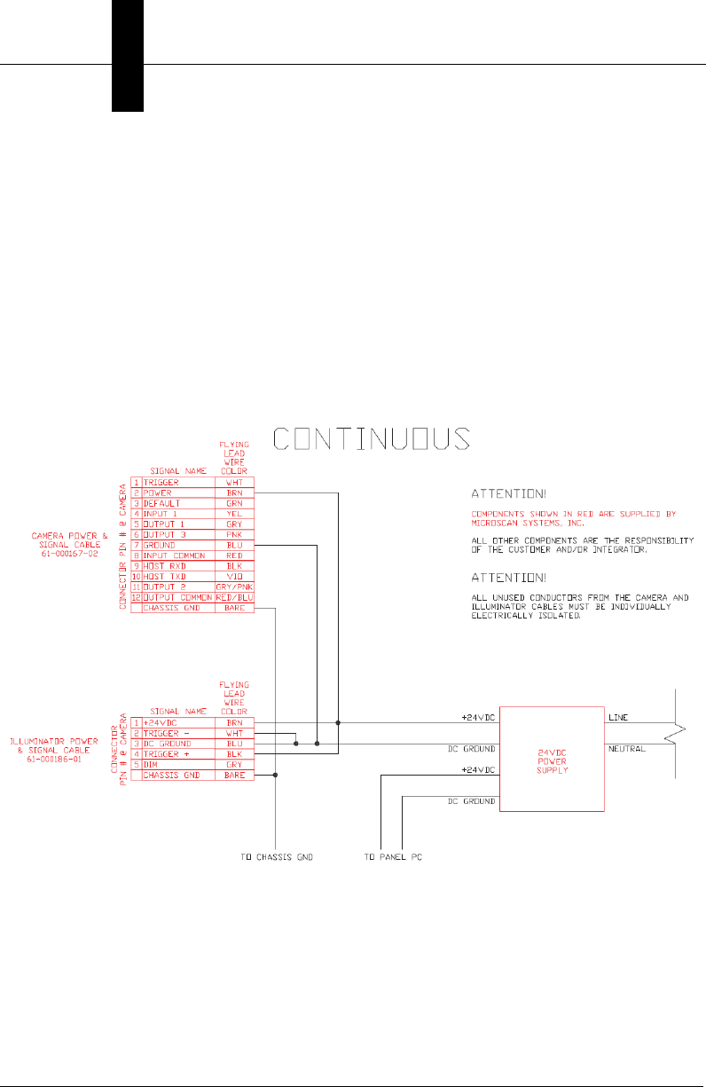
Hardware Wiring
The following diagram shows the pin assignments of the camera, illuminator, and power
supply, and shows how to wire the devices for VMI operation.
The part sensor is not shown. The wiring will vary depending on whether the sensor is
configured NPN or PNP. Please see chapter two of the Vision HAWK User Manual for
information on connecting a part sensor.
General Details
Inspection Failed and Trending Alarm signals are supplied as 24 volt DIO signals.
These signals can be used to activate a diverter mechanism, send a notification, stop the
line, or a variety of other functions.

Application Tips
Hardware and
Software Installation
1
Getting Started with VMI 1-5
Application Tips
If your application includes low-contrast printed barcodes, the minimum edge contrast parameter
may be below the required threshold. This will result in failing grades reported by VMI.
Microscan recommends that you follow GS1’s solutions for failed minimum edge contrast:
• Variations in ink weight in different parts of a symbol (non-uniformity of ink spread and
ink viscosity): Adjust press settings to ensure even inking.
• Show-through of contents: Use more opaque packaging material or print a white
underlay prior to printing the symbol.
• Fluctuations in background reflectance (areas of darker material in recycled corrugated
substrates, for example): Use a more consistent substrate or one with higher reflectance.
• Excessive ink spread: Apply correct bar width reduction (BWR) when originating the symbol.
It may also be necessary to mount Microscan’s MAX Illuminator (NER-011660301G) closer
to the target barcode and to use continuous illumination to optimize lighting uniformity.
Continuous illumination requires a special cable: Microscan’s QX Cordset, Smart Series
Illuminator-to-QX-1, Continuous Power (61-000204-01).

Chapter 1Hardware and Software Installation
1-6 Getting Started with VMI
PC Requirements and Settings
Minimum PC Requirements
• CPU: Intel ATOM N2600 1.6GHZ Dual Core or Greater
•Minimum RAM: 2 GB
• Minimum One USB and One 100 BaseT Network Connection
• Display Resolution: 1024 x 768
• Hard Drive: 250 GB or More
• Operating System: Windows 7 Professional 32-bit, SP1
• 3.0 Windows Experience Index
Recommended PC Requirements
• CPU: Intel ATOM N2600 1.6GHZ Dual Core or Greater
• RAM: 4 GB or More
• Wireless Network Adapter
• One USB and Two 100 BaseT Network Connections
• Resolution: 1024 x 768
• Hard Drive: 250 GB or More
• Operating System: Windows 7 Professional 32-bit, SP1
• 4.0 Windows Experience Index
Recommended Windows Settings
• Disable Windows Updates.
• Disable screen savers.
• Disable Sleep/Hibernation (found in Power Settings).
• Set the Network Adapter and camera to the same Subnet.
• Auto-hide the taskbar.
Recommended Accessories
• Uninterruptable Power Supply (UPS)
The UPS provides a safety factor that protects your vision inspection system from
power outages and brownouts.
Data Archiving
The VMI system can be configured to store images and data on the hard drive.
Microscan suggests that you follow your own configuration management standard
operating procedures to maintain hard drive space and to archive VMI results.
For optimum performance, use a PC with a Windows Experience Index of 4.0 or
higher. At higher production line rates, i.e. higher parts per minute, data and images
may be dropped from the collected results if the PC is too busy processing or
displaying graphics.

Modifications Required when Using VMI with a Panel PC
Hardware and
Software Installation
1
Getting Started with VMI 1-7
Modifications Required when Using VMI with a Panel PC
The following items may be required when using VMI with a Panel PC. Please review the
list and complete all required modifications before running VMI.
• Go into the BIOS Setup by pressing the DEL key when powering the unit. In BIOS
Setup you should see a blue screen with several tabs at the top. Select Chipset and
then go to South Bridge Configuration. In South Bridge Configuration, 5 lines down,
you should see a setting called Restore on AC Power Loss. Select Always On and
save settings.
• Connect the PC to the internet and activate Windows.
• Install the touchscreen driver (supplied on the CD if using a BSI Panel PC).
• Install the graphics driver (supplied on the CD if using a BSI Panel PC).
•Go to Control Panel > Power Options > High Performance > Change Plan
Settings > Change Advanced Power Settings and set the following:
• Turn off Hard Disk after 0 Minutes (Never)
• Sleep > Hibernate after 0 Minutes (Never)
• Right-click
Computer > Properties > Windows Experience Index > Adjust Visual Effects
.
•Custom – Disable everything except the following:
• Show Shadows under Mouse Pointer
• Show Shadows under Windows
• Slide Open Combo Boxes
• Smooth Edges of Screen Fonts
• Smooth-Scroll List Boxes
• Use Drop Shadows for Icon Labels on the Desktop
• Use Visual Styles on Windows and Buttons
• Right-click the taskbar, select Properties, and enable Auto-hide the taskbar.
• Install Acrobat.
• Disable Windows Update.
• Install AutoVISION.
• Install VMI.
Chapter 1Hardware and Software Installation
1-8 Getting Started with VMI
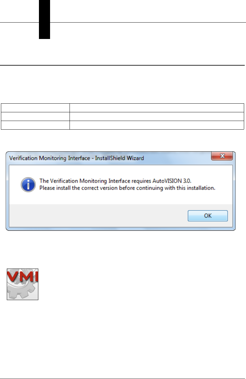
VMI Installation
Important: VMI is a plug-in module that is based on Microscan’s AutoVISION software.
AutoVISION must be installed before VMI is installed. Each release of VMI is tied to a
particular version of AutoVISION. The VMI installer contains logic to ensure that the
correct version of AutoVISION is installed using the following table:
• If the correct version of AutoVISION is not installed on your PC, the following message
will appear, prompting you to install the correct version of AutoVISION:
Note that the version of AutoVISION shown here is only an example. Each subsequent
version of VMI will be tied to a subsequent version of AutoVISION.
• When you have installed the correct version of AutoVISION and VMI, you will see the
VMI launch icon on your desktop.
AutoVISION Version VMI Installer Action
Required Version Installs VMI
Any Other Version Notifies the user to install the correct version of AutoVISION
Launching VMI
Hardware and
Software Installation
1
Getting Started with VMI 1-9
Launching VMI
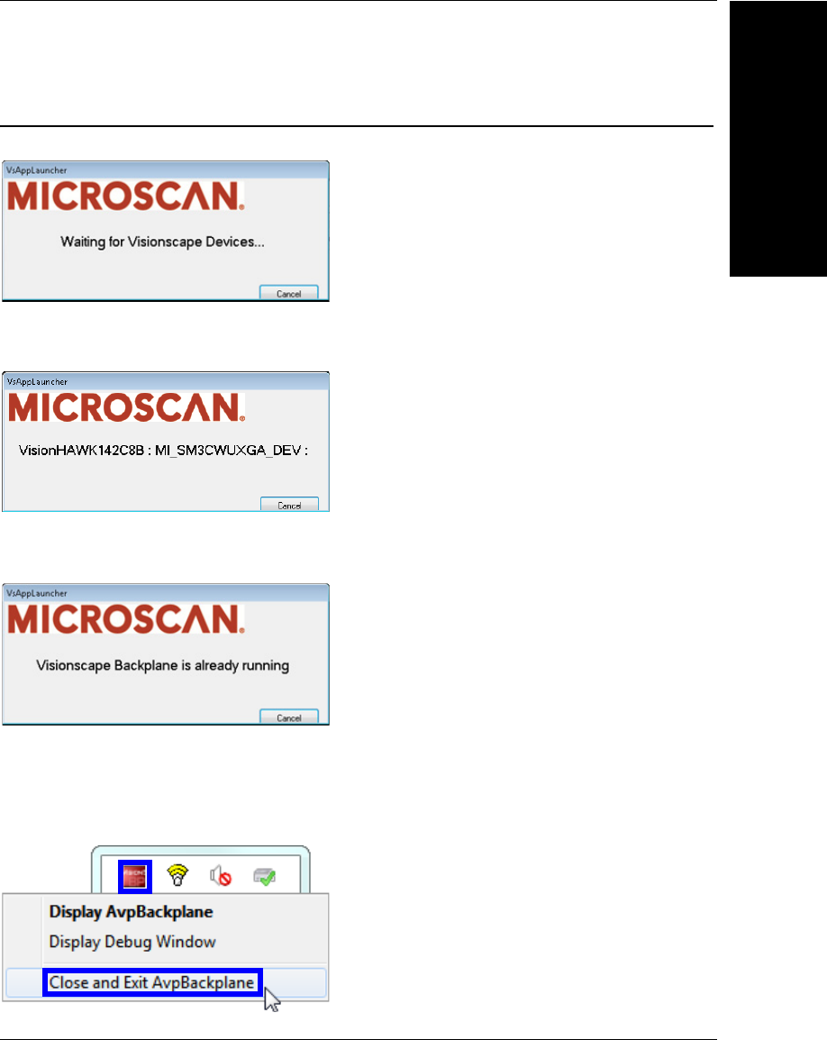
When you launch VMI, the software will look for your Vision HAWK on the VMI network.
Once communications are established between the Vision HAWK and the network, the
following display will show the camera’s identifying information:
If you have previously run VMI and the Visionscape Backplane did not close, the following
message will appear:
If you see this message and you need to close the Backplane, right-click the Backplane
icon and select Close and Exit AvpBackplane.
Note however that closing the Backplane is not required, and that VMI will start even if you
leave the Backplane open. This example is for information only.

Chapter 1Hardware and Software Installation
1-10 Getting Started with VMI

Getting Started with VMI 2-1
2
The VMI Interface
2
CHAPTER 2
The VMI Interface
This section describes the features of the VMI user interface.

Chapter 2The VMI Interface
2-2 Getting Started with VMI
The VMI User Interface
The Verification Monitoring System’s user interface is very similar to that of AutoVISION,
especially AutoVISION’s Verification functionality. AutoVISION is Microscan’s standard
machine vision interface for jobs of moderate complexity. To learn more about
AutoVISION, refer to the AutoVISION Software User Manual, which can be found in the
Download Center on the Microscan website.
Similarities between VMI and AutoVISION Setup
The AutoVISION user interface is very similar to the VMI user interface. The primary difference
is that AutoVISION features multiple tools while VMI is designed solely for Verification and
print quality trending. The Connect and Image tabs are the same between AutoVISION
and VMI. Refer to the AutoVISION Software User Manual to learn more about connecting to
different devices or adjusting camera settings.
The following AutoVISION installation and configuration processes demonstrate the
similarity between VMI and AutoVISION.
Similarities between VMI and AutoVISION Setup
The VMI Interface
2
Getting Started with VMI 2-3
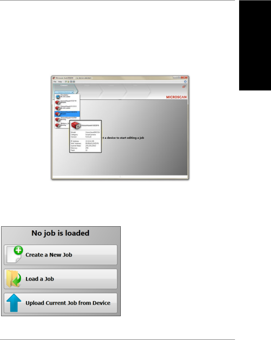
Select a Device
AutoVISION's Connect view allows you to select your device and configure its settings,
and to create a new job.
Camera: Vision HAWK C-Mount.
Emulator: The software emulator allows you to work from saved images without hardware.
Once a device is selected, you can Create a New Job, Load a Job from a saved .avp file
on your PC, or Upload Current Job From Device (your camera).
•Job: A completed program, including image acquisition, tools, and reporting.
•Tool: A self-contained set of steps used to perform a specific task.
Note: When selecting the Emulator, there is no option to upload a job.
The Connect menu
provides a list of
available devices.
Hover the mouse
over a device to
see its details.
Chapter 2The VMI Interface
2-4 Getting Started with VMI
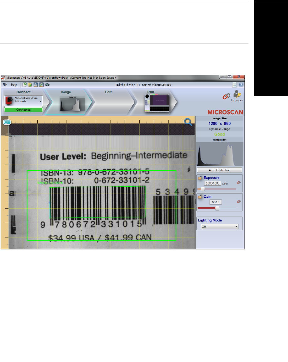
Adjust Camera Settings
Once you have selected your camera or the Emulator and created a new job, you will
move to the
Image
view. This view allows you to
Auto Calibrate
the camera, and to manually
adjust the camera's Exposure, Gain, and Focus, and also to set the Lighting Mode (On,
Off, or Strobe).
Note: If you load a job from your PC or upload a job from the camera, you will automatically
move to the Edit view.
Similarities between VMI and AutoVISION Setup
The VMI Interface
2
Getting Started with VMI 2-5
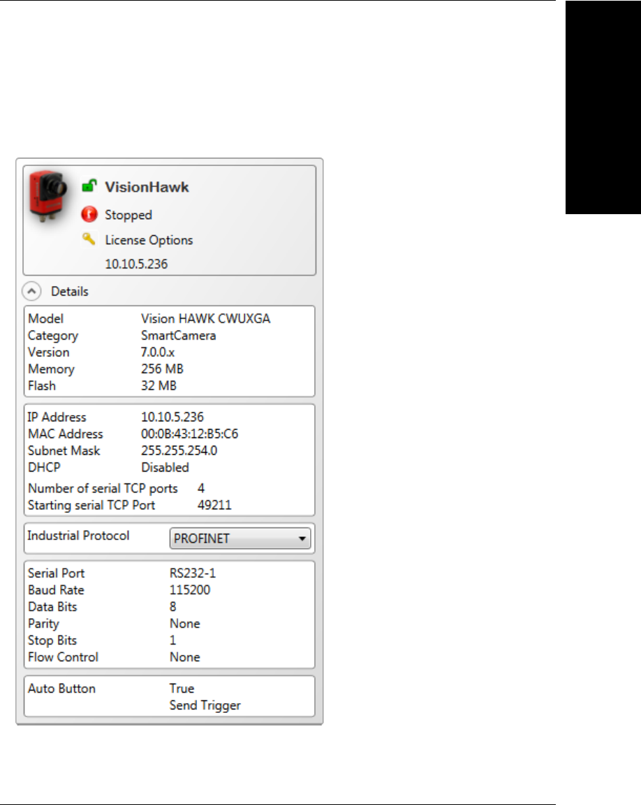
You can return to the Connect view and click the Modify button to adjust additional
camera settings, such as TCP/IP settings, RS-232 settings, Ethernet settings, Industrial
Protocol, and AutoVISION button settings. You can also rename your camera
(alphanumeric characters only - [0-9], [a-z], and [A-Z]). Click the Apply button when
you have adjusted the camera's settings as needed.

Chapter 2The VMI Interface
2-6 Getting Started with VMI
Differences between VMI and AutoVISION Setup
VMI is a plug-in module that replaces the Edit and Run views of AutoVISION with a user
interface that has been developed for barcode verification and print quality trending.
Microscan strongly recommends that VMI be used only with the Vision HAWK C-Mount
Smart Camera. VMI grades barcodes according to ISO standards that state very specific
setup requirements. Internal lighting and autofocus, used in other Vision HAWK models,
do not allow the necessary setup control. Microscan cannot guarantee satisfactory results
when cameras other than the Vision HAWK C-Mount are used.
User Access Levels
The VMI Interface
2
Getting Started with VMI 2-7
User Access Levels
VMI enables a Security service that provides four levels of password-protected access.
Password protection is enabled by default and cannot be disabled, whereas AutoVISION
makes password protection optional. Password protection ensures that vision jobs and
settings cannot be changed by unqualified personnel. The four levels of access are:
Operator:
Can only monitor the Run view of VMI. Cannot access other screens or change settings.
Supervisor:
Can switch to Edit mode and adjust ROI (region of interest) positions, re-train tools,
change the selected device, save the current job, or load a different job. The Supervisor
cannot modify the parameters of the current job, or add or remove tools.
Engineer:
An Engineer has full access to all settings. They are only restricted from changing
passwords.
Administrator:
The Administrator has full access to all settings, including the ability to change the
passwords for the various access levels.
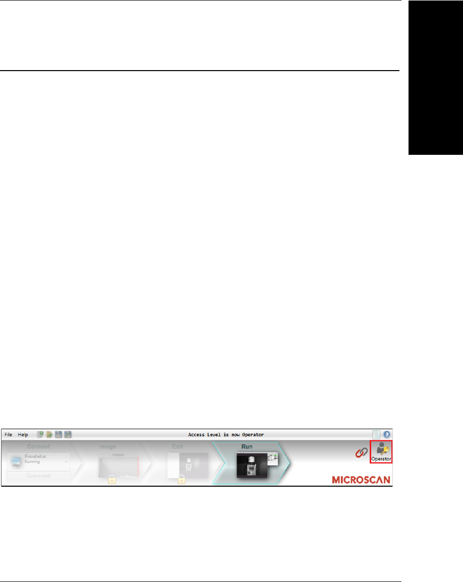
Changing the Access Level
VMI will always start up with the access level set to Operator, which means you are
locked out of configuration settings in the user interface. You can change your access
level by clicking the icon highlighted here:
Chapter 2The VMI Interface
2-8 Getting Started with VMI
Note that your current access level is always displayed below the key button. Click this
button to display the following dialog:
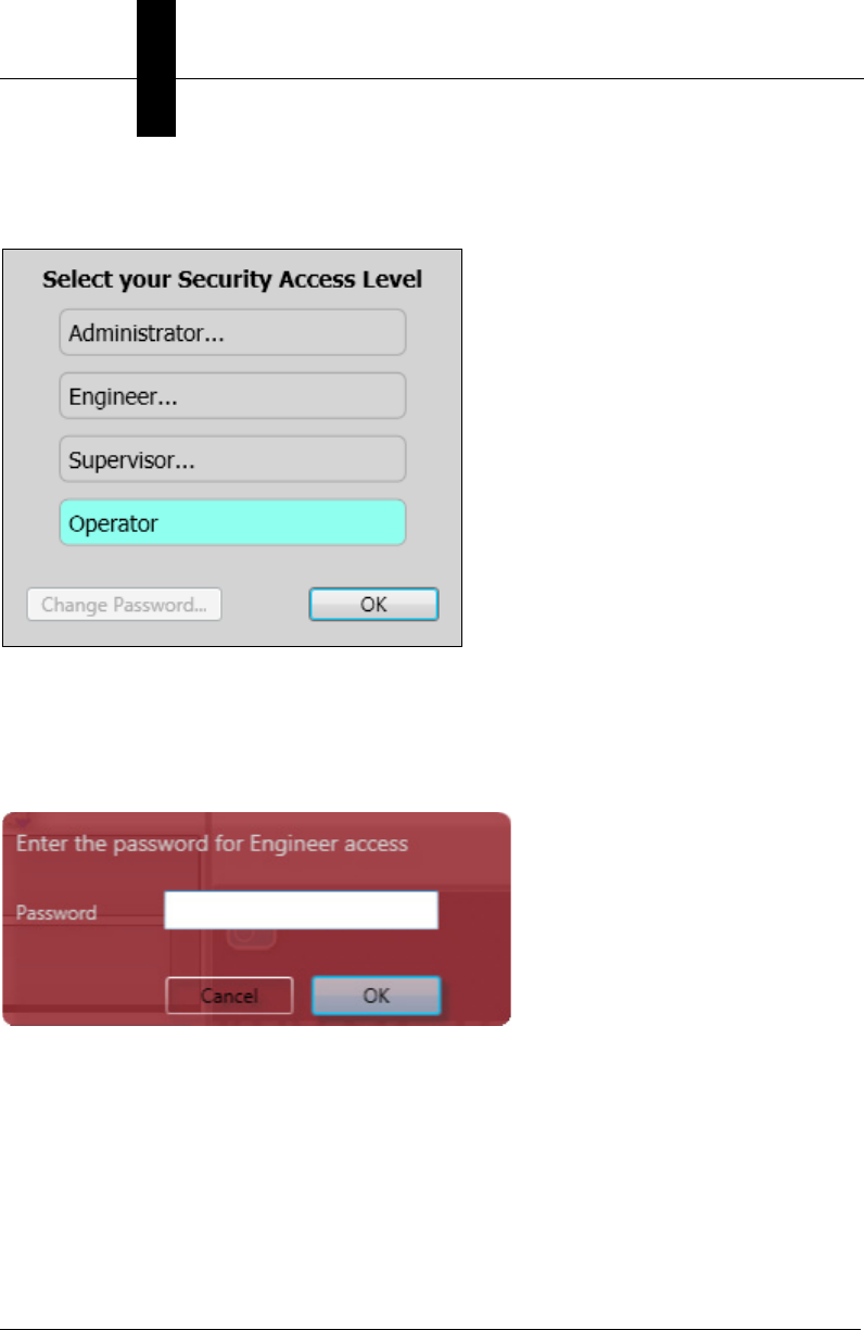
This simple dialog provides a button for the four access levels. The highlighted button
shows the current access level. In the example above, the current access level is
Operator. If you wish to switch to any of the other 3 modes, click that button and you will
be asked for the corresponding password. So if you wanted to switch to Engineer, you
would click the Engineer… button, and:
Enter the password, click OK, and if the password is correct, the access level is changed.
If incorrect, an error message is displayed and the access level remains unchanged.
User Access Levels
The VMI Interface
2
Getting Started with VMI 2-9
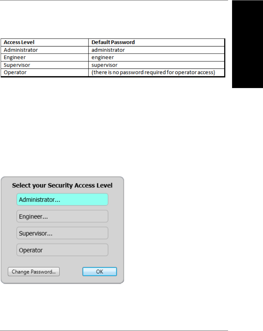
The default passwords for the various access levels are as follows:
Note that once you have entered the password for a particular level, you don’t need to
enter a password to reduce your access level. For instance, if you currently have
Administrator access, you can simply click on the Engineer or Supervisor buttons, and
your access level will be reduced instantly without the need to enter a password. You only
enter a password when you are increasing your access level.
Important: If the system is inactive for five minutes, the access level will revert to Operator.
Changing Passwords
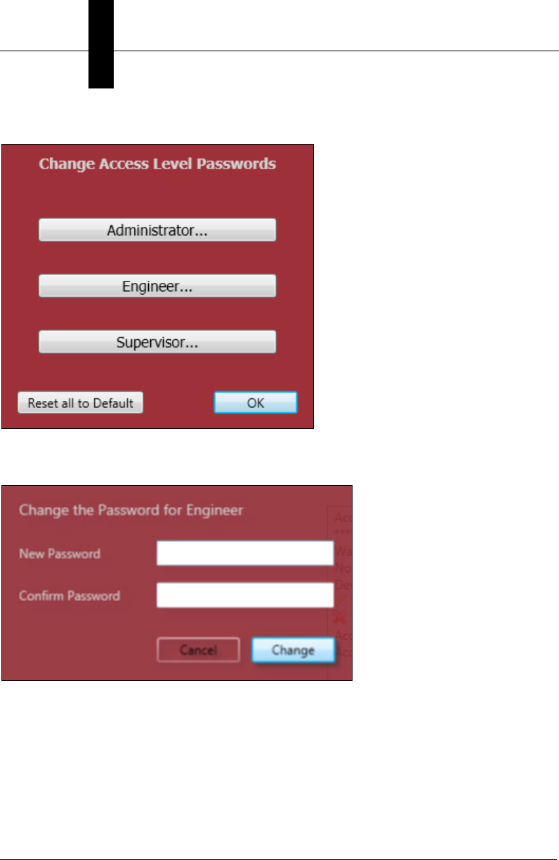
In order to change the password for any access level, you must be an administrator. If you
change your access level to Administrator, the Change Password… button at the bottom
of the dialog will become enabled:
Chapter 2The VMI Interface
2-10 Getting Started with VMI
Clicking Change Password… brings up this dialog:
Click the button that corresponds to the access level whose password you wish to modify,
and the standard change password dialog will be presented:
Click the Reset all to Default button, and all passwords will be reverted to the factory
defaults, as documented above.
User Access Levels
The VMI Interface
2
Getting Started with VMI 2-11
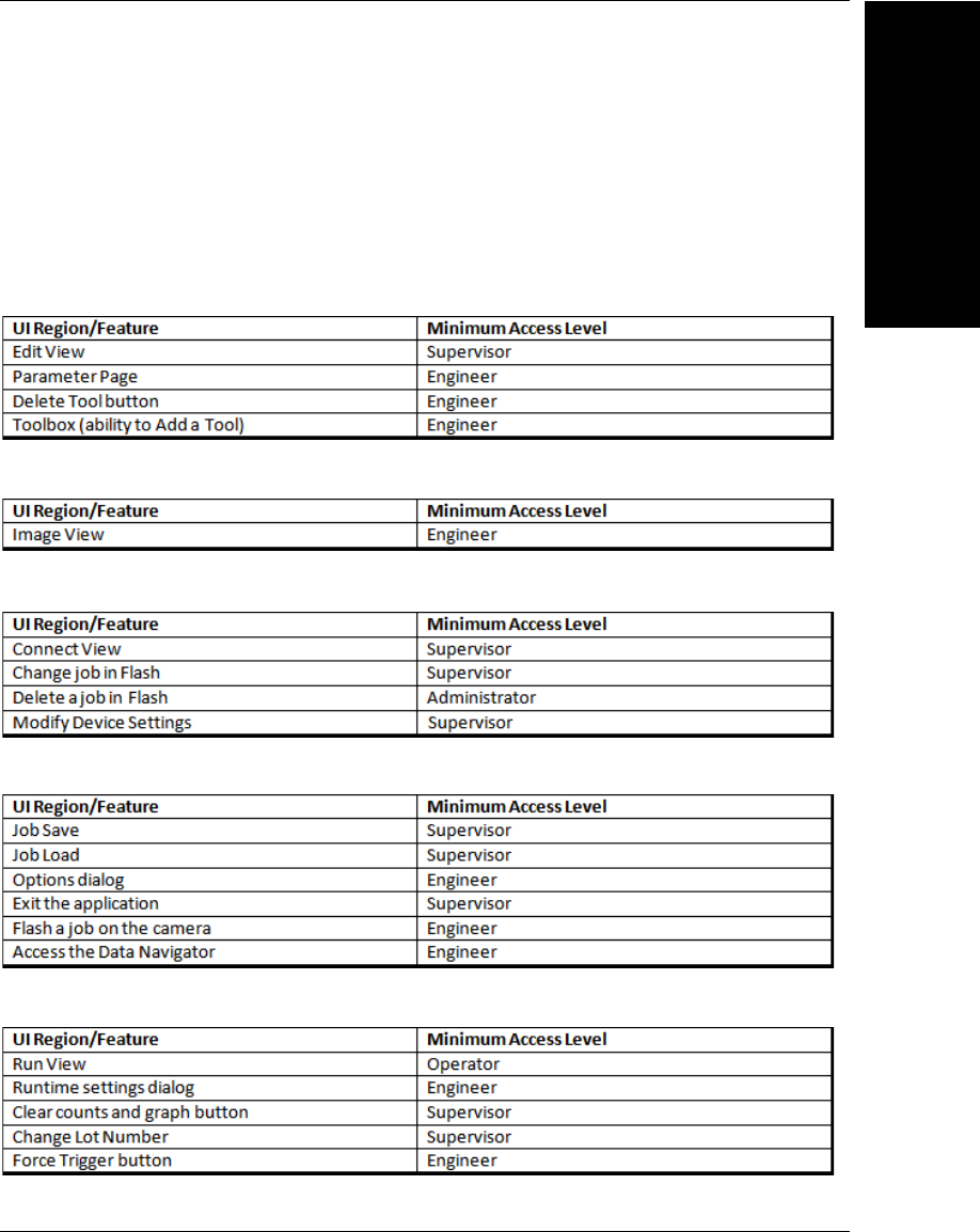
Minimum Access Levels
The VMI plug-in defines what the minimum access level will be for the various regions and
features of the AutoVISION user interface, as well as for several of the VMI-specific
features. Following is a list of the securable areas within AutoVISION, and what the
minimum access level is for each:
Edit View
Image View
Connect View (Device Selection View)
Application-Wide Options
VMI Run View

Chapter 2The VMI Interface
2-12 Getting Started with VMI

Getting Started with VMI 3-1
3
Starting VMI
3
CHAPTER 3 Starting VMI and Creating
Your First Job
This section describes how to start VMI and create your first job.
Chapter 3Starting VMI and Creating Your First Job
3-2 Getting Started with VMI
Starting VMI for the First Time
VMI will always try to automatically connect to the last device that you had selected. When
you run VMI for the very first time however, you will need to select a device manually. This
is done by going to the Connect view (just as in standard AutoVISION). Note however
that VMI will always startup with an access level of Operator, which means you are locked
out of the Connect view. So change your access level to Engineer first (refer to the
previous section on Security Settings for the default Engineer password).
Select a Device
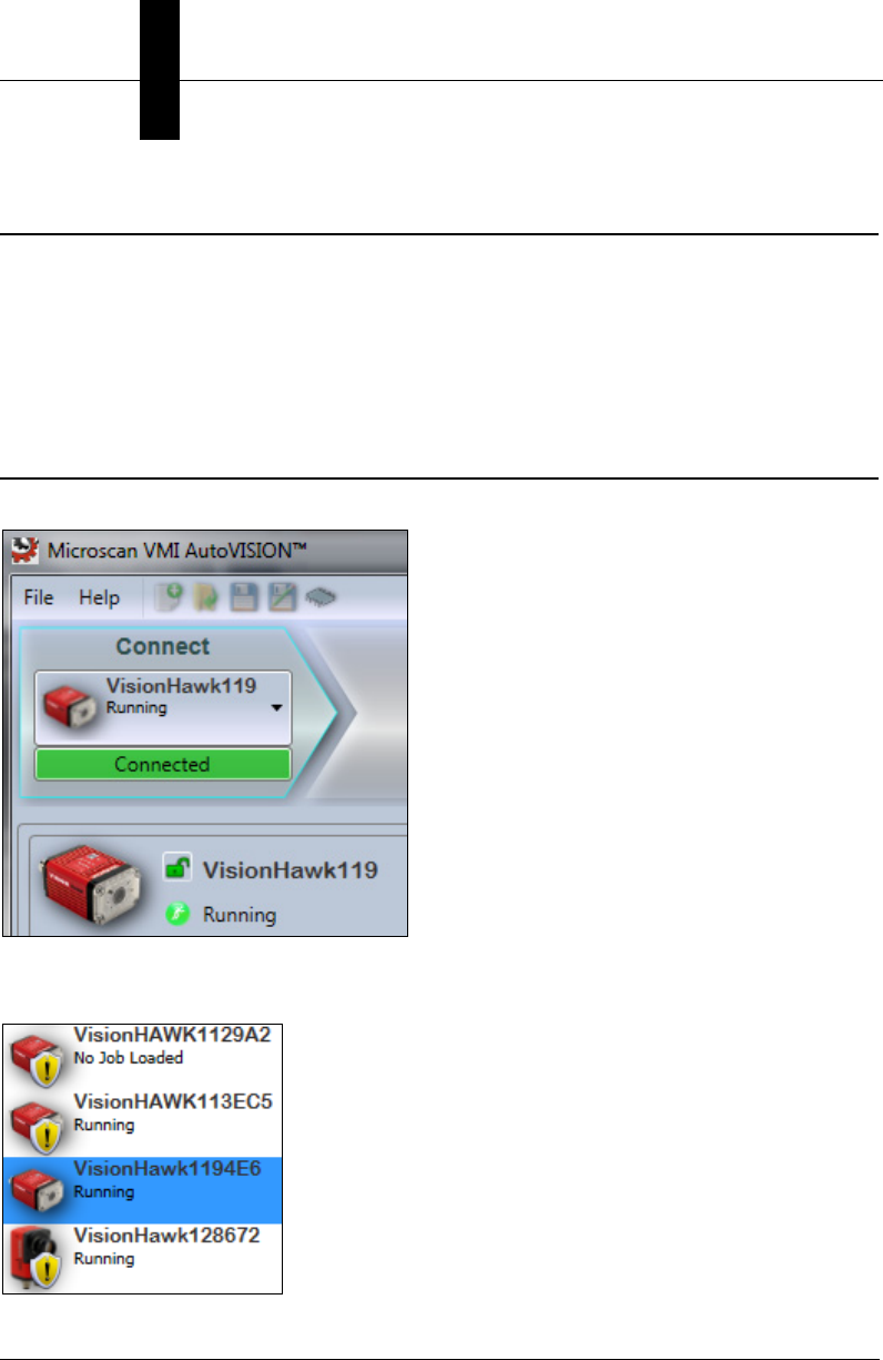
Select a smart camera from the dropdown list in the upper left corner of the UI:
Note that your smart camera must have an AutoVISION VMI license in order for it to be
selected in VMI:
Select a Device
Starting VMI
3
Getting Started with VMI 3-3
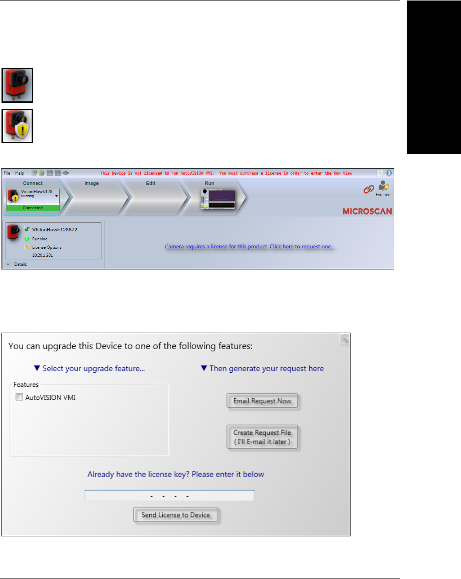
Devices that don’t have a license for VMI will be displayed with the shield icon:
If you select an unlicensed device, you will see this screen:
Note the error message in the message bar. You will be locked into this screen; you
cannot create jobs or enter the Run view. You are presented with a link that you can click
on if you wish to request a license upgrade for your camera. Clicking the link will present
you with the following dialog:
This is the standard license upgrade dialog from AutoVISION, but in this case, you can
use it to request a license for AutoVISION VMI.
= Licensed
= Not Licensed
Chapter 3Starting VMI and Creating Your First Job
3-4 Getting Started with VMI
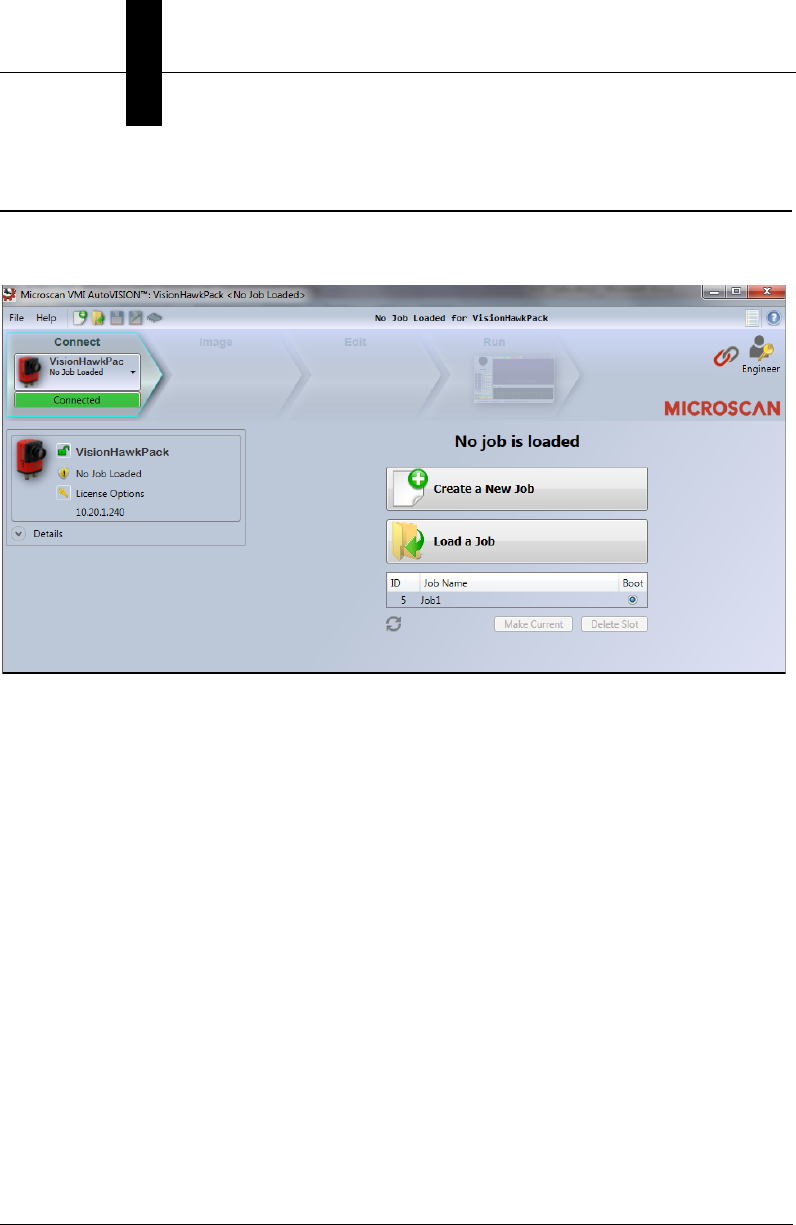
Create a New Job
Once you have selected a licensed device, you are presented with the standard options in
the Connect view:
Click the Create a New Job button and a new Verification inspection will be created for
you. This is not a blank job as in standard AutoVISION, but is instead a fully configured
Verification job. The new job is configured as follows:
• A Verification Tool is inserted.
– The Good grade tolerance is set to 1.0.
– The Fair grade tolerance is set to 0.5.
• Logic is added to the Verification Tool so that it may also perform the following checks.
– A height measurement of the symbol.
– A match string comparison against the decoded data in the symbol.
– Separate counts are maintained of how many symbols were graded as good, fair
and poor.
– Trend analysis logic.
• The Digital Outputs are automatically set up as follows:
– Output 1 is assigned to the inspection failed signal.
– Output 2 is assigned to the Trend Analysis alarm output.
• All data required at runtime is selected for upload.
Adjust the Image
Starting VMI
3
Getting Started with VMI 3-5
Adjust the Image
When the job creation is complete you will be taken to the Image view. The VMI Image
view is the same as that in AutoVISION. Use this view to adjust your lighting and camera
focus, gain and exposure settings.
See the next page for Image Adjustment Guidelines.
Chapter 3Starting VMI and Creating Your First Job
3-6 Getting Started with VMI
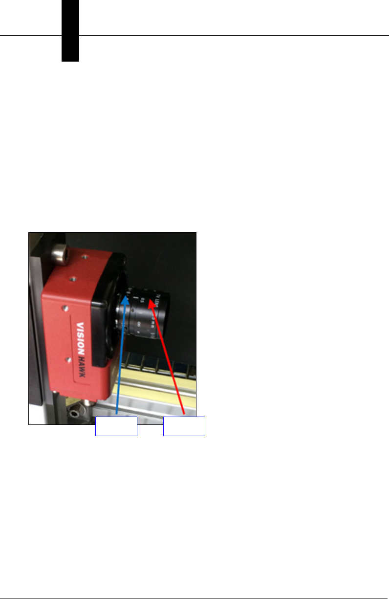
Image Adjustment Guidelines
Use the following notes as guidance when focusing the camera lens.
• Position a box with a printed barcode in the trigger position in front of the Vision HAWK.
• Go to VMI’s Image view and turn on live video mode.
• Adjust the lens focus to provide the sharpest focus.
– It is suggested that the MAX 300 (light) power be disconnected while you perform
the focus adjustment. With the light off, the F-stop will need to be fully opened (1.4)
and the exposure will need to be set between 8,000 and 50,000. Set the exposure
high enough that you can see the barcode and focus the camera lens.
– After adjusting focus, lock the focus using the locking screws / thumb screw.
– Reconnect the power cable to the MAX 300 (light).
• Turn off live video mode.
• Adjust the lens F-stop to the dot between 4 and 8 on the lens and tighten the lock screw.
• Set the gain and exposure so that the image is not blurred when capturing an image of
a moving part. The barcode should be easily seen in the image.
• Take a new picture to update the image.
F-Stop Focus
Edit the Job
Starting VMI
3
Getting Started with VMI 3-7
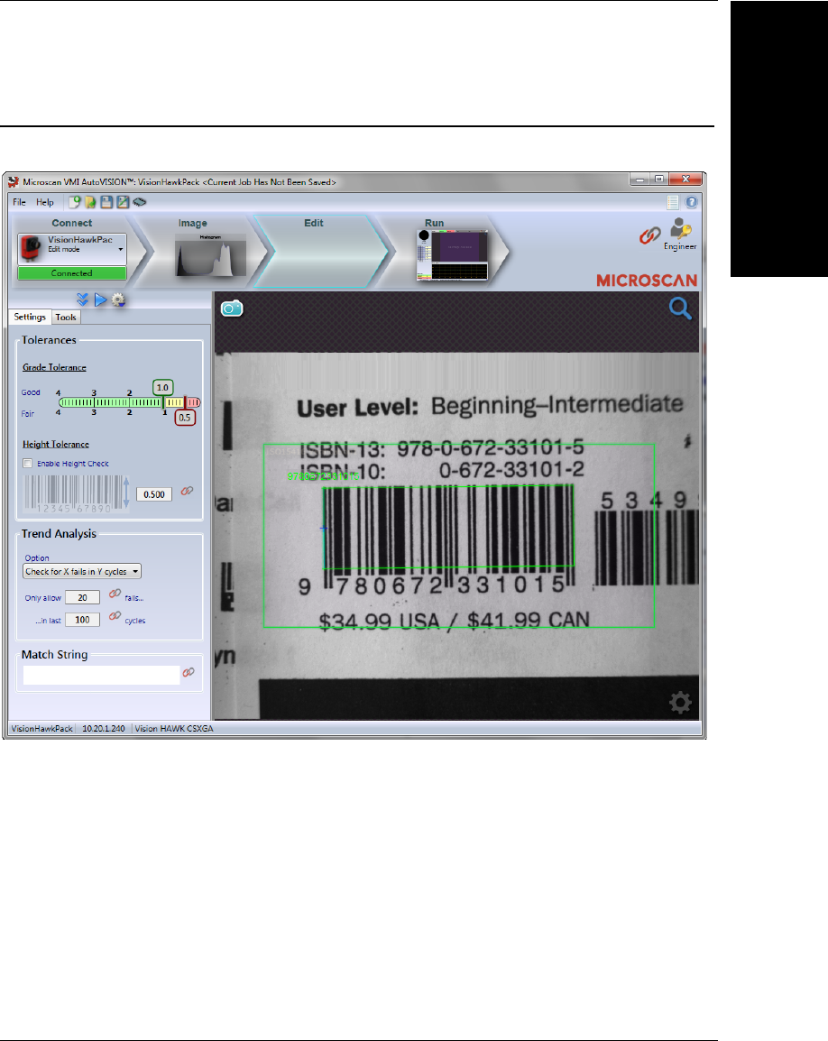
Edit the Job
Move to the Edit view, and you will see the following:
Note that the access level is set to Engineer at this point, and note the Settings and
Tools tabs at the left of the user interface.
Chapter 3Starting VMI and Creating Your First Job
3-8 Getting Started with VMI
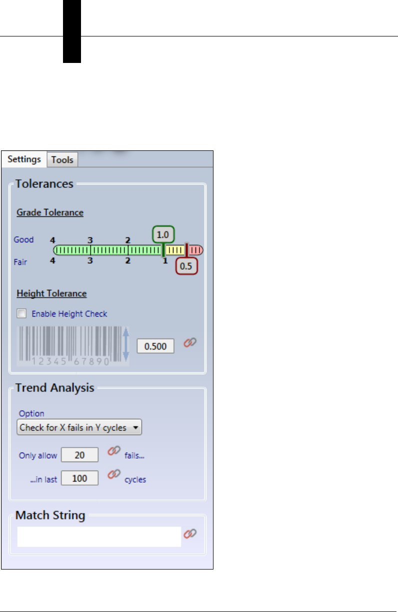
Settings Tab
The Settings tab provides a high-level view of the most common parameters that you are
likely to adjust in your Verification inspection. It allows you to adjust the inspection
tolerances, as well as to setup the trend analysis and optional match string check.
Edit the Job
Starting VMI
3
Getting Started with VMI 3-9
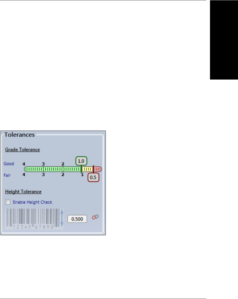
Tolerances
The Tolerances section is used to control the pass/fail state of your verification inspection.
The Grade Tolerance control is used to set the limit on what grades will be considered
Good, what grades will be considered Fair and what grades will be considered Poor. In
the example above, grades of 1.0 and above are good, 0.5 – 1.0 are fair, and grades
below 0.5 are poor. The sliders can be grabbed and dragged in 0.1 increments in order to
adjust the tolerances.
The Height Tolerance area allows you to enable a check on the height of the symbol. This
check is turned off by default, so click the Enable Height Check button if you wish to enable
this functionality. The text box in the lower right corner can then be used to set the measured
height of the symbol in inches. Symbols that have a measured height below the user-defined
tolerance will be rejected.
Important: You must calibrate the Verification Tool in order for Height Check to work. If the
Verification Tool is not calibrated, the height value will be logged as 0.
Chapter 3Starting VMI and Creating Your First Job
3-10 Getting Started with VMI
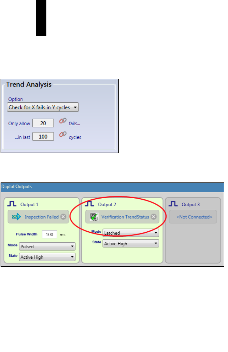
Trend Analysis
The Trend Analysis section can be used to configure VMI to check for simple trends in
Verification grading.
If the selected trend is detected, the job can be configured so that a digital output on the
smart camera will turn ON. This can be configured by going to the Tools tab, selecting the
Inspection Outputs tool, and looking at the Digital Output selections:
Edit the Job
Starting VMI
3
Getting Started with VMI 3-11
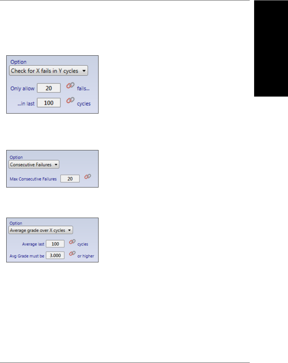
Three Trend Analysis options are provided:
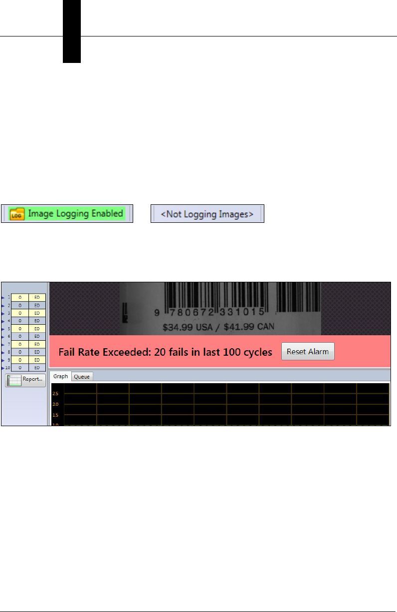
1. Check for X Fails in Y Cycles (Default):
In the above example, the trend status output will turn on if there are ever 20 failures in
the last 100 inspections.
2. Consecutive Failures:
In the above example, the trend status output will turn on if you receive 20 consecutive rejects.
3. Average Grade over X Cycles:
In the above example, an average grade will be maintained over the last 100 cycles, and
if it should ever fall below 3.0, then the trend status output will turn on. Note that you
must perform at least 100 inspections before the average will begin to be checked.
Note: A failed Matchcode attempt will fail the overall inspection but has no effect on the
grade of the symbol being inspected.
Chapter 3Starting VMI and Creating Your First Job
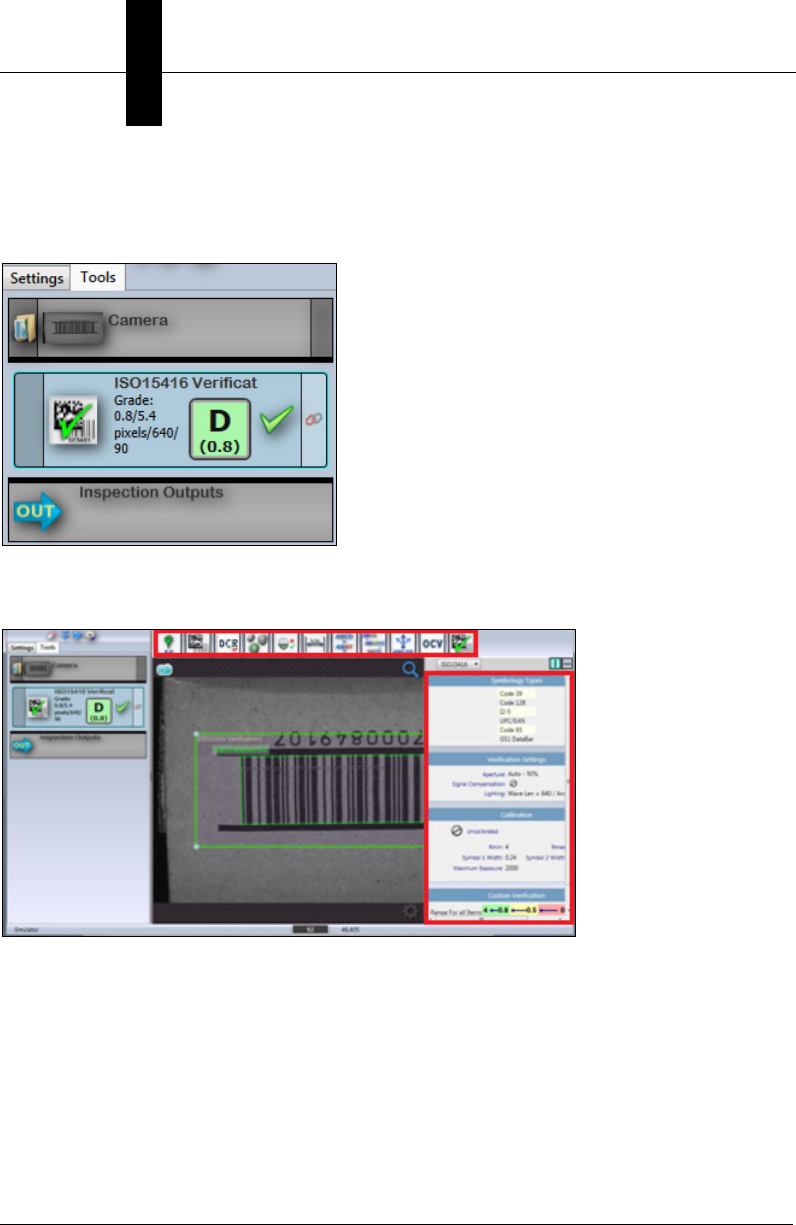
3-12 Getting Started with VMI
Tools Tab
Switch to the Tools tab to see the list of tools that make up your job. This view gives you
more granular control over the tool parameters in your inspection.
Note that if you have Engineer access and you switch to the Tools tab, the parameters will
become visible on the right side of the view, and the Toolbox will become visible above the
image as well:
You can now insert tools into your job if necessary, and adjust all parameters. When the
Tools tab is selected, you have the same capabilities as you do in the Edit view of standard
AutoVISION.
Additional details about available tools can be found in the Edit chapter of the AutoVISION
Software User Manual (autovisionmanual.pdf, located in
C:\Microscan\Vscape\Documentation after AutoVISION installation) and also in
AutoVISION Help, which can be accessed from the File menu in AutoVISION.
Edit the Job
Starting VMI
3
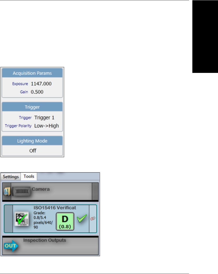
Getting Started with VMI 3-13
Camera
Allows you to configure camera parameters relating to image capture including Exposure,
Gain, Trigger, and Lighting Mode.
Important: Changing camera parameters will override any calibration that may have been
performed. Re-calibrate after changing camera parameters if calibration is required for
your application.
Verification Tool
Chapter 3Starting VMI and Creating Your First Job
3-14 Getting Started with VMI
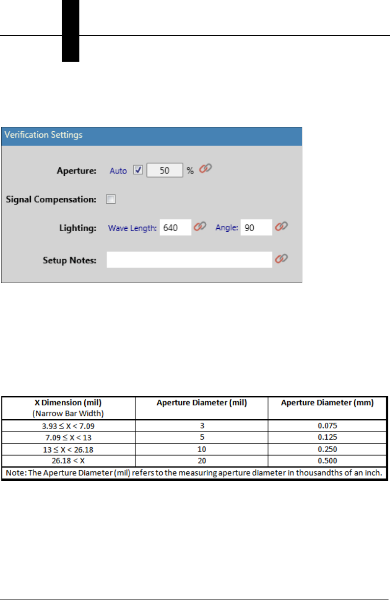
Verification Settings
The Verification Tool has settings for Aperture, Wavelength, and Angle that must be
defined by the user. The aperture is set to 50% of the cell size by default.
Aperture, Wavelength, and Angle
You must modify the aperture, wavelength, and angle manually before running a
verification job. The wavelength of the illumination provided by the MAX 300 is 625 nm.
This value, along with the lighting angle of 45 degrees, should be included in any formal
grading report and should be entered into the Symbol Quality Verification Tool in VMI.
After calibration, select the required aperture based on the symbol to be graded.
The table below provides a guideline for correct aperture settings for verification to the ISO
15416 standard.
Edit the Job
Starting VMI
3
Getting Started with VMI 3-15
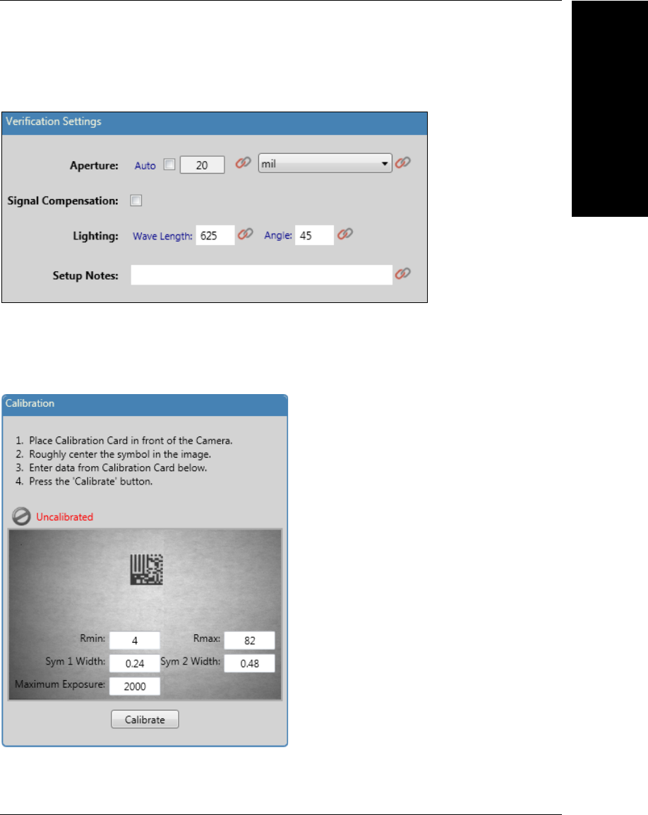
An example of how to configure the verification settings for a 30 mil ITF-14 symbol is
shown here.
Calibration
As part of the calibration process, the Exposure Time setting of your camera will be
adjusted. Use the Maximum Exposure value in the Calibration dialog to set the maximum
Exposure Time that can be set.
Chapter 3Starting VMI and Creating Your First Job
3-16 Getting Started with VMI
Calibration Setup
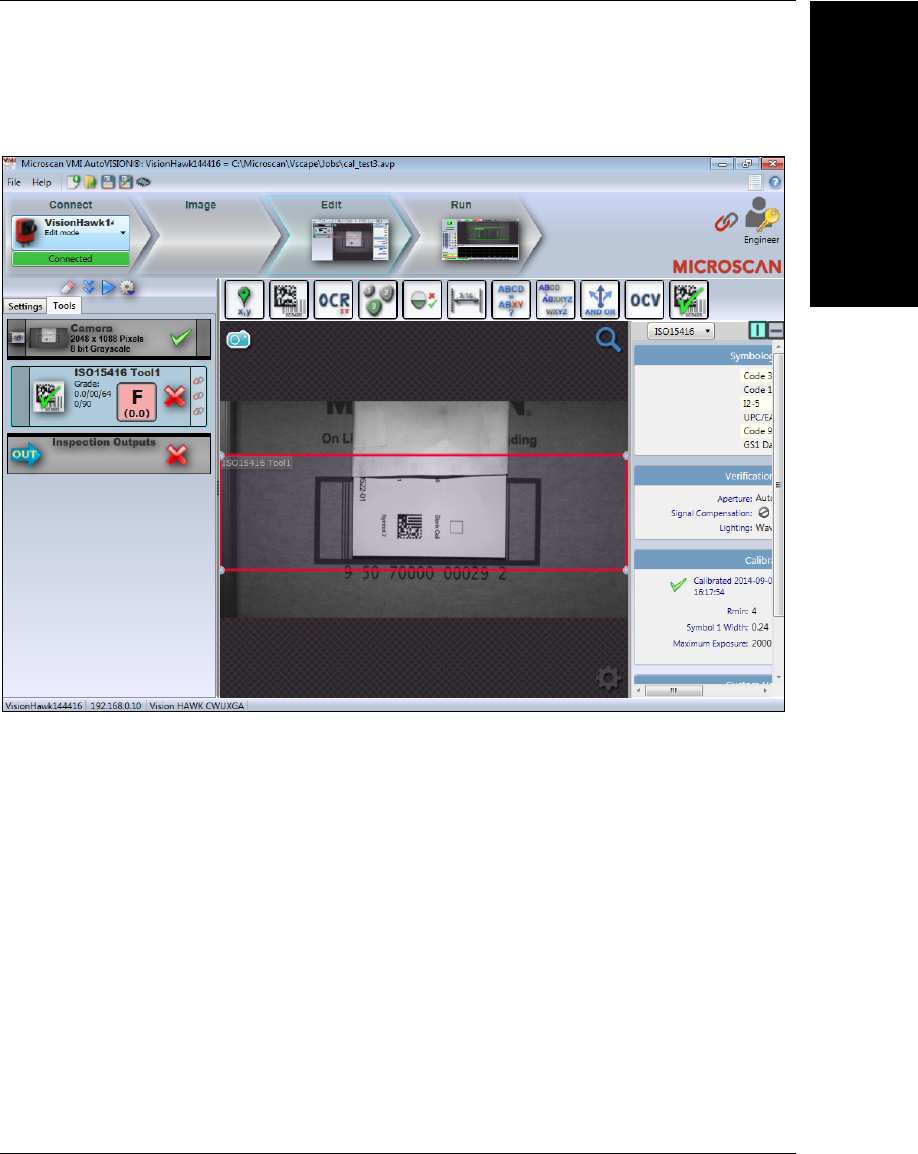
• Go to VMI’s Edit view, click the Tools tab, and select the Verification tool.
• Click on the Calibration button in the Verification menu and enter the nominal Rmin,
Rmax, Symbol 1 width and Symbol 2 width listed on the card.
• Position the calibration card symbol in the center of the Verification ROI as shown in
the image below. This symbol should be centered as closely as possible to be verified
as reliably as possible.
– If the field of view is greater than 4 inches, use Symbol 2, the larger of the two
symbols. If less than 4 inches, use Symbol 1.
– Be sure not to have both symbols in the ROI. If both are within the red ROI box, find
a small piece of white paper to cover the unneeded symbol.
• Click the Calibrate button.
• Microscan strongly recommends that you develop a mechanical assembly or jig that
allows accurate, repeatable calibration. If a mechanical assembly to hold the
calibration card is not available, it can be helpful to have two people assist in
calibration. One person can position the calibration card accurately, and the second
person can execute the calibration process in VMI.
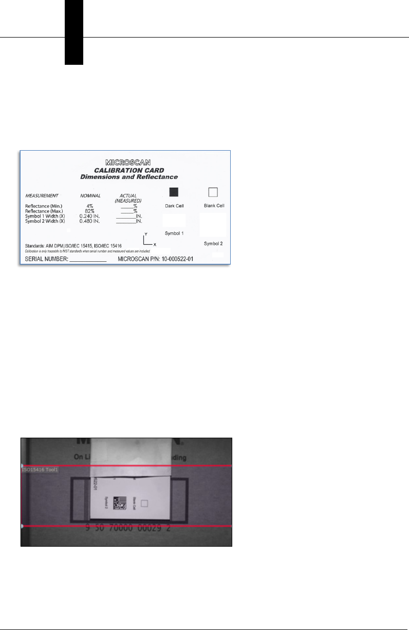
This is the standard Calibration Card that is included with all verification kits. Note that is does not
include a serial number or measured reflectance data. A NIST-Traceable version of the Calibration
Card, which includes a serial number, measured reflectance data, and a Measurement Certificate, is
available for purchase. Contact Microscan to purchase the NIST-Traceable Calibration Card with
Measurement Certificate. NIST-Traceable serial numbers and measured values are not required for
verification unless your particular industry requires them.
Edit the Job
Starting VMI
3
Getting Started with VMI 3-17
Once the camera is calibrated, the Calibration dialog will show the date and time that the
calibration was performed.
If calibration fails, check the following items:
• Check that the camera is in sharp focus.
• Adjust the F-stop on the camera lens to make the white area of the calibration card
appear light gray as seen in the Calibration window.
• Ensure that verification symbol is contained within the verification tool’s region of
interest when calibrating.
• Do not have both calibration symbols in the verification tool’s region of interest.
• If the camera field of view is greater than 4 inches use the larger calibration symbol for
calibration.
Configuration and use of AutoVISION verification is covered in detail in the Symbol
Quality Verification Tool chapter of the AutoVISION Software User Manual
(autovisionmanual.pdf, located in C:\Microscan\Vscape\Documentation after
AutoVISION installation) and also in AutoVISION Help, which can be accessed from
the File menu in AutoVISION.
Chapter 3Starting VMI and Creating Your First Job
3-18 Getting Started with VMI
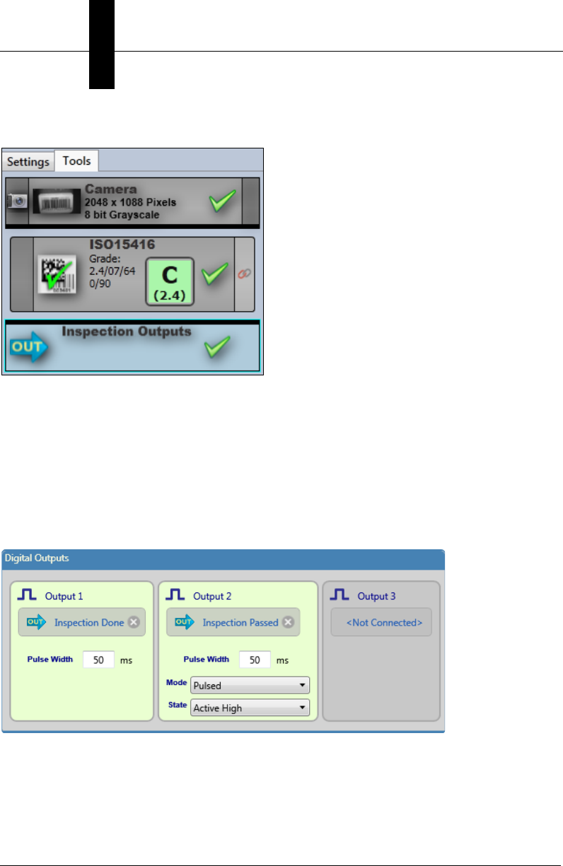
Inspection Outputs
The Inspection Outputs tool is used to communicate the results of your inspection to the
outside world. You can output results via Digital I/O, or as string data sent via the serial
port or the Ethernet port (via TCP/IP).
Digital Outputs are commonly used to:
• Indicate the Inspection Passed or Failed to be used with the reject station;
• Indicate that a Trending condition has occurred to stop the production line or to
initiate a print head purge.
Digital Outputs
•Inspection Done: Pulses the I/O point at the end of each inspection cycle. The length
of the pulse is user-configurable. The default pulse length is 50ms.
•Inspection Passed: Activates the output if the inspection passes. The pass state can
be connected to any tool in the job for output.
•Inspection Failed: Activates the output if the inspection fails. The fail state can be
connected to any tool in the job for output.
Edit the Job
Starting VMI
3
Getting Started with VMI 3-19
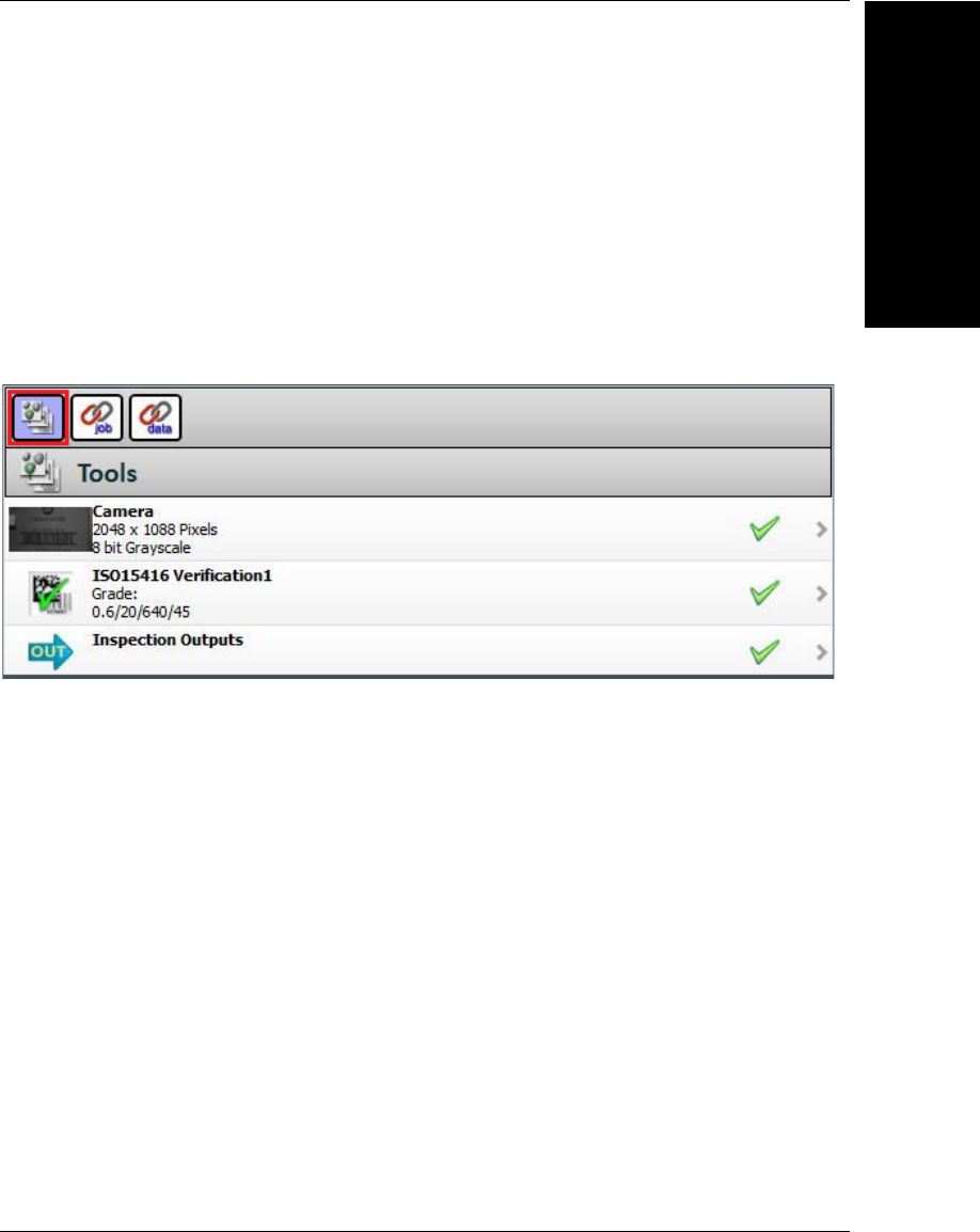
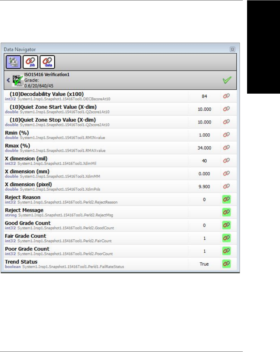
VMI Inspection Results
VMI has many inspection result outputs that provide verification feedback. These outputs
are available through the Data Navigator, which can be opened by clicking the Microscan
Link icon at the upper right of the VMI interface or by typing Ctrl + D.
Some of the result outputs are the verification grade, inspection status, barcode data,
counters, trending status, and reject codes that represent the reject cause. Use the Data
Navigator in Edit mode to select the outputs you would like available at runtime and
assign them to integers, strings, and booleans. Click the Tools button – the top left button
in the Data Navigator – to view the tools used in the current job and to select the outputs in
those tools to be linked.
Chapter 3Starting VMI and Creating Your First Job
3-20 Getting Started with VMI
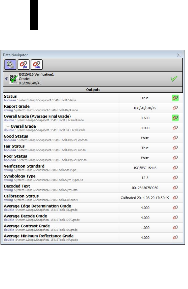
ISO 15416 Outputs
Edit the Job
Starting VMI
3
Getting Started with VMI 3-21
ISO 15416 Outputs (Continued)

Chapter 3Starting VMI and Creating Your First Job
3-22 Getting Started with VMI
Reject Codes
Many of the outputs are self-explanatory. For example, the good inspections counters are
named “Good Grade Count” and are integers. In the case of rejects, there is a reject code
(integer) and a reject message (string). The reject codes are defined as follows:
0 = Pass
1 = Improper Verification Tool setup (all the required inputs are not connected)
2 = Verification Tool did not run
3 = No Read
4 = Bad Grade
5 = Height Fail
6 = Match Fail
Ranked Order of Reject Precedence
1 = Improper Verification Tool setup
2 = Verification Tool did not run
3 = No Read
6 = Match Fail
4 = Bad Grade
5 = Height Fail
Trending Status (Boolean)
The item identified as the
Fail Rate
in VMI indicates the current trending status. When this
value is set to
0
, the Alarm message is displayed and then reset to
1
when the alarm is cleared.
Edit the Job
Starting VMI
3
Getting Started with VMI 3-23
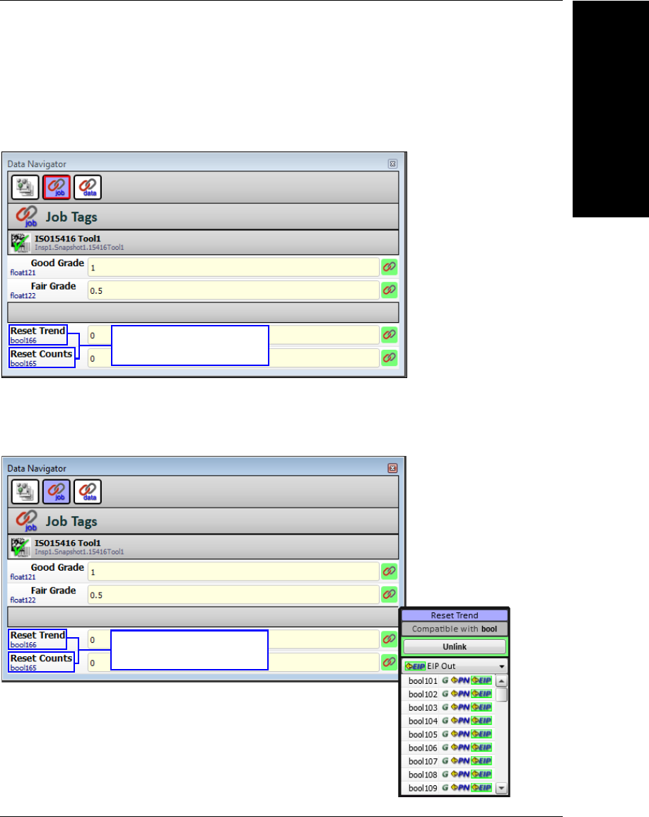
VMI Inputs
Using the Data Navigator, VMI input parameters can be modified at runtime. Click the Job
button – the second button at the top of the Data Navigator – to view the VMI input parameters.
By default, the input parameters are set to be controllable by the VMI user interface.
If the Link icon is clicked, the linked value can be changed to a value that can be addressed
by a PLC using EtherNet/IP or PROFINET industrial protocols. Once the links to these items
are changed from the defaults, the VMI user interface functionality associated with these
items will be effectively disabled due to the Link value superseding the user interaction.
Reset Trend: bool166
Reset Counts: bool165
Reset Trend: bool166
Reset Counts: bool165
Chapter 3Starting VMI and Creating Your First Job
3-24 Getting Started with VMI
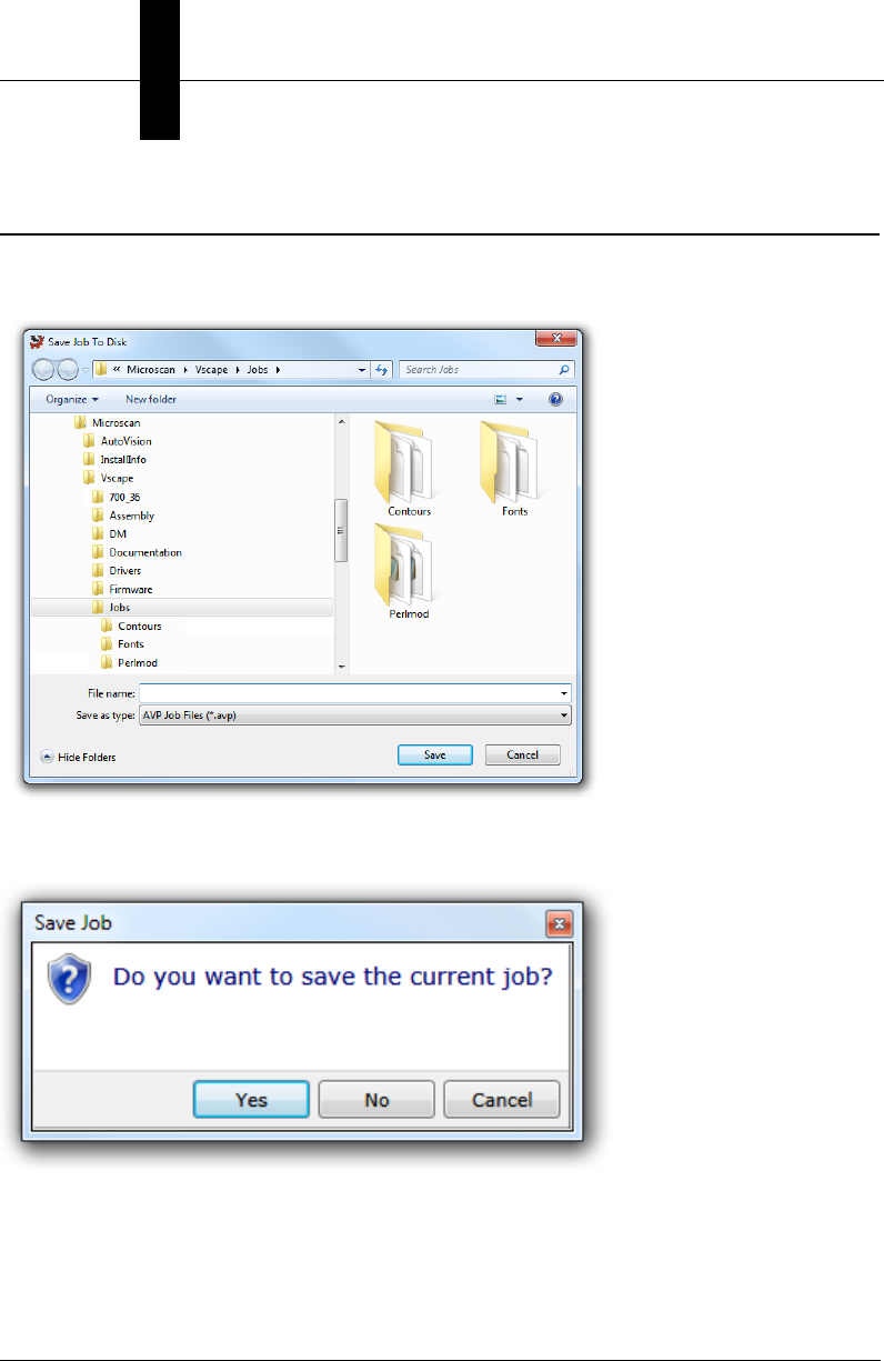
Save the Job
Once you have created and edited a job, select Save or Save As from the File menu to
save the job. The default job location is C:\Microscan\Vscape\Jobs.
You will also be prompted to save your current job if you attempt to close VMI or open
another job without first saving the current job.
Open a Job
Starting VMI
3
Getting Started with VMI 3-25
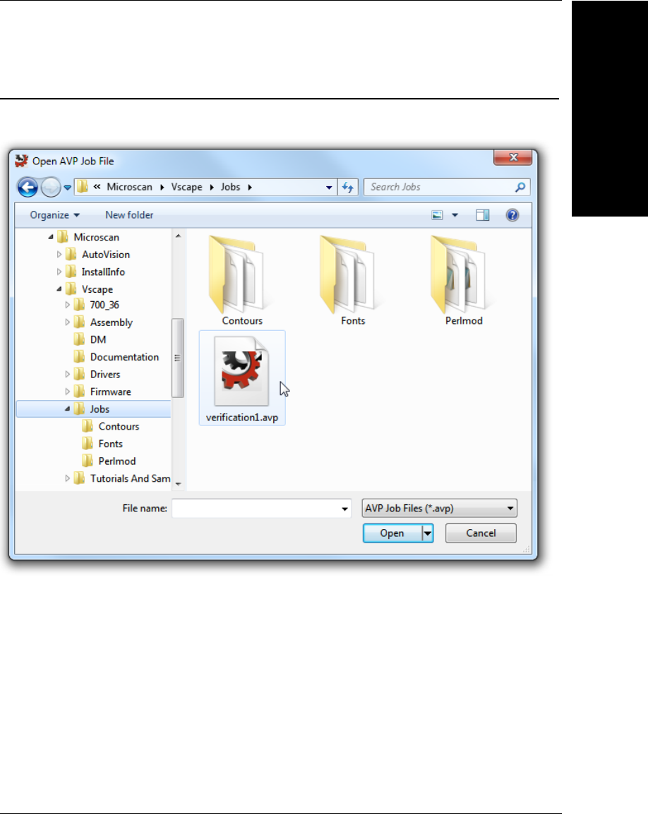
Open a Job
To open a job when VMI is already open, navigate to the File menu and select Open. The
job file will be retrieved from the default job location C:\Microscan\Vscape\Jobs.

Chapter 3Starting VMI and Creating Your First Job
3-26 Getting Started with VMI

Getting Started with VMI 4-1
4
Runtime and Job
Monitoring
4
CHAPTER 4 Runtime and Job
Monitoring
This section describes the features of the VMI runtime interface.
Chapter 4Runtime and Job Monitoring
4-2 Getting Started with VMI
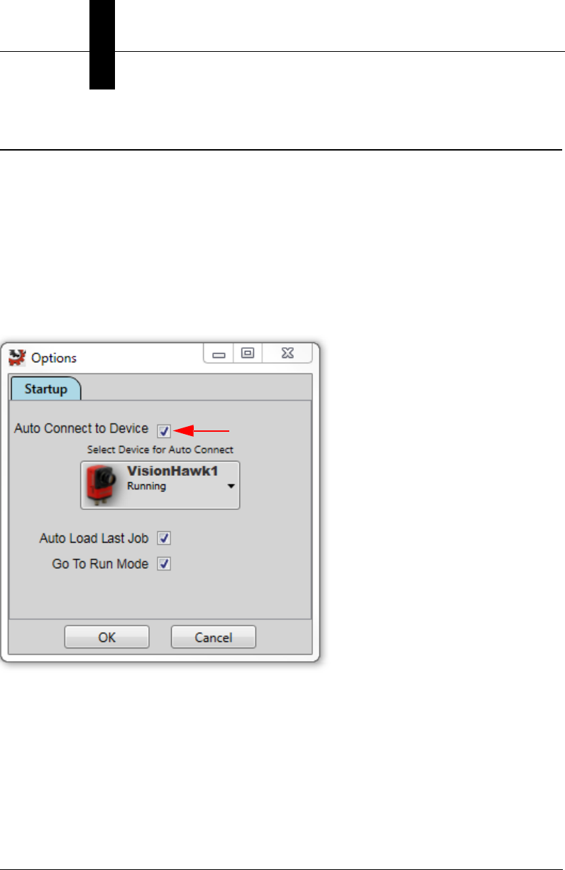
VMI Startup Options
Each time you start VMI, the device to which you were last connected will be selected by
default, and the last job you loaded will be reloaded by default. Assuming that the device
is selected and that the job is downloaded successfully, VMI will automatically enter the
Run view. The security access level will be set to Operator by default, and you will be
locked into the Run view until you change the access level.
Auto Connect behavior can be disabled from the Engineer or Administrator access levels
by selecting Options from the File menu and disabling the Auto Connect to Device option
by unchecking the box indicated below. After Auto Connect to Device has been disabled, a
user with an access level of Supervisor or higher can select the desired camera.
Important: Be sure that the camera is not configured to run in Continuous Mode.
Successful VMI operation requires the camera to be triggered.
VMI Runtime
Runtime and Job
Monitoring
4
Getting Started with VMI 4-3
VMI Runtime
The runtime view provided by VMI is completely different than that provided by standard
AutoVISION. The VMI Runtime is intended to provide feedback and logging capabilities
that are specific to a Verification application.
Chapter 4Runtime and Job Monitoring
4-4 Getting Started with VMI
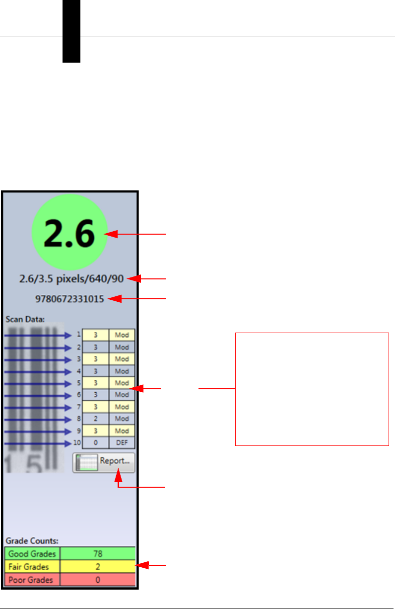
Data Panel
The Data Panel on the left side of the Run view provides real-time verification data for
each inspected part. The Verification Tool analyzes 10 separate scans to arrive at the final
grade. The Scan Data section of the Data Panel provides details about which parameter
had the lowest grade for each scan. If you hover your mouse pointer over an abbreviation
in the scan data rows, a popup will appear with the full name of that parameter.
Refer to the AutoVISION Software User Manual for comprehensive information about how
Symbol Quality Verification works.
Grade
ISO Grade
Decoded Text
Shows
Worst Grade
from Each of
10 Scans
Click Here to View Full Verification Report
(Refer to the “Symbol Quality Verification Tool”
chapter in the AutoVISION Software User
Manual for comprehensive information about
Verification Reports.)
Count of the Number of
Good, Fair, and Poor Grades
Verification Parameter Abbreviations
•ED = Edge Determination
• Dec = Decode
•Con = Symbol Contrast
•Mod = Modulation
•MEC = Minimum Edge Contrast
•MR = Minimum Reflectance
•DEF = Defects
• DAB = Decodability
•QZ = Quiet Zone
VMI Runtime
Runtime and Job
Monitoring
4
Getting Started with VMI 4-5
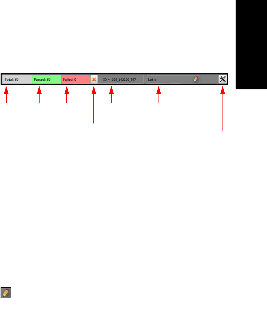
Image and Information Bar
The image is presented for every inspected part when possible (Note that images may be
dropped if the camera is sending images faster than the PC can display them). An
information bar is positioned just above the image to provide the overall inspection counts,
an image ID, and an optional lot number.
Clear Counts Button: You must have Supervisor access or higher to access this button.
Unique ID: This ID is a time stamp that is taken at the moment the image is received from
the camera and it is used when logging data and images. The ID uses the following format:
DDD_HHMMSS_mmm
DDD = Day of the Year (1-365)
HH = Hours
MM = Minutes
SS = Seconds
mmm = Milliseconds
Lot Number: This can be any text that you wish, but you must have Supervisor access or
higher in order to modify it. This value will be logged for each cycle whenever data logging
is enabled. Click the icon shown below to edit the text, and press the enter key when you
are done with your edits.
Options Dialog: You must have Engineer access in order for this button to be enabled.
Clicking it will open the Runtime Options dialog. Refer to the Runtime Options section for a
description of this dialog.
Total
Inspected
Total
Passed
Total
Failed
Clear Counts
and Graph
Unique ID for
Each Image
Optional Lot
Number
Click to Show
Runtime Options
Dialog
Chapter 4Runtime and Job Monitoring
4-6 Getting Started with VMI
History Panel
This panel is intended to provide some historical perspective on your inspection
performance. Two tabs are provided – Graph and Queue.
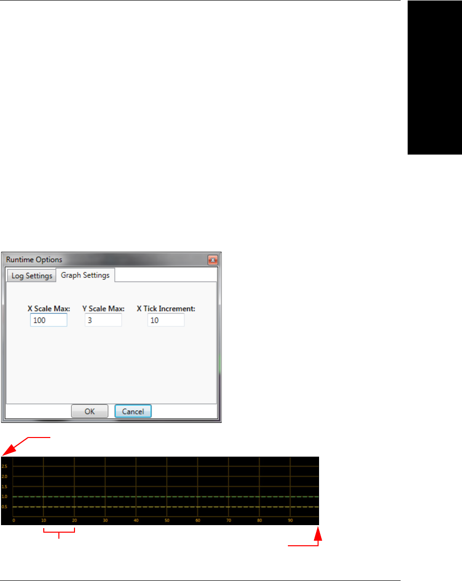
Graph
The graph tab shows you a real-time graph of the last 100 grades. 100 is the default, but
this can be increased or decreased by going to the Runtime Options dialog and adjusting
the X Scale Max parameter. The contents of the graph will be cleared whenever you clear
the counters. The X and Y graph ranges are:
X Graph Max. = 100 – 2,000
Y Graph Max. = 1.0 – 4.0
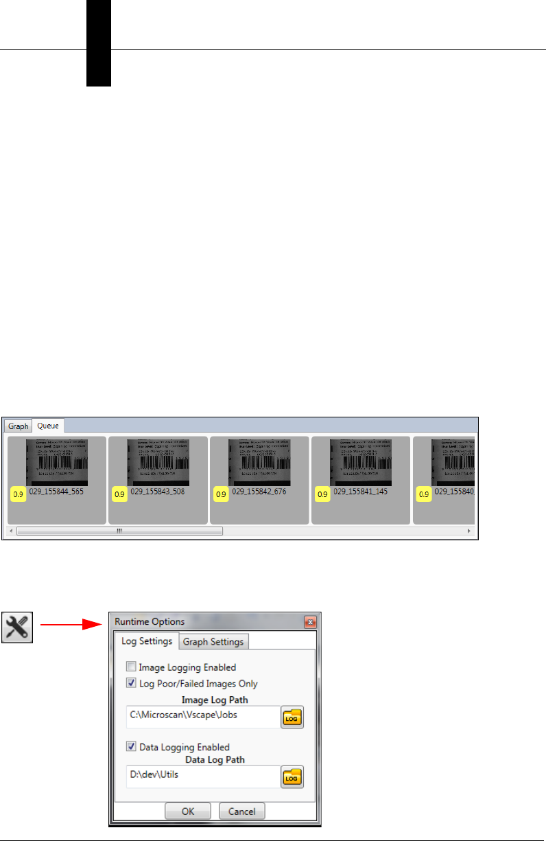
Queue
The queue tab allows you to look at a queue of the last 10 images and their grades, as
well as the unique ID assigned to each.
Note: If the PC is unable to upload the image due to the trigger rate, the grade and unique
ID will be displayed without an image.
Runtime Options
The runtime options are only available if you have Engineer access or higher. Open the
dialog by clicking the icon in the upper-right corner of the Run view:
VMI Runtime
Runtime and Job
Monitoring
4
Getting Started with VMI 4-7
Log Settings
The options in this tab control the logging behavior of VMI. Both Data Logging and Image
Logging are disabled by default.
Image Logging Enabled: Check this box if you wish to save images to disk.
Log Poor/Failed Images Only: Check this box if you only want to save images for failed
inspections.
Image Log Path: Select the folder where images will be saved.
Data Logging Enabled: Check this box if you want to log data for each inspection cycle to
a .csv file.
Data Log Path: Select the folder where your data logs should be saved.
Graph Settings
These options control the display of the graph in the Run view.
Y Scale Max
X Scale Max
X Tick Increment
Chapter 4Runtime and Job Monitoring
4-8 Getting Started with VMI
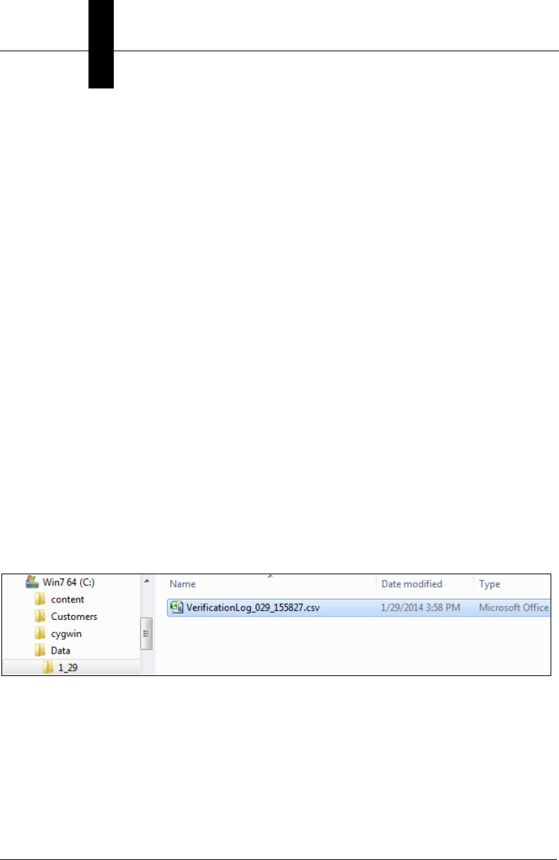
Data Logging Details
When data logging is enabled, data from each inspection cycle will be saved to a .csv file.
This comma-separated values file can be opened directly in Microsoft Excel. The file will
be named with a time stamp that is generated when the file is first created. The format of
the file name is as follows:
VerificationLog_DDD_HHMMSS.csv
DDD = Day of the Year (1-365)
HH = Hours
MM = Minutes
SS = Seconds
Log files are saved in separate folders for each day of the year. The format of the sub-folders
is as follows:
M_DD
M = Month
DD = Day of the Month
For example, if you have chosen to log your data to the folder C:\Data, and the date today
is January 29th, then a subfolder named 1_29 will be created under C:\Data, and the log
file will be saved there:
VMI Runtime
Runtime and Job
Monitoring
4
Getting Started with VMI 4-9
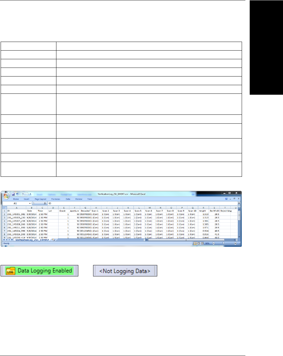
The data saved for each cycle is as follows:
A sample data log:
The active state of data logging is indicated at the bottom of the Run view.
Data Description
Unique ID The time stamp ID that identifies this inspection cycle.
Date The date of the cycle.
Time The time of the cycle.
Lot The text you enter in the Lot field of the Run view.
Grade The numeric grade for the cycle.
Aperture
The aperture contained in the data log is the size of the aperture
measured in 1/10th of a pixel. For example, an aperture value of 45
in the data log would equal 4.5 pixels.
Decoded Text The decoded symbol data.
Scan 1 – Scan 10 The worst grade for each scan, and the verification parameter ID (in
parentheses) that produced that grade.
Height The measured height of the symbol in inches. If the Verification Tool
is not calibrated, the height value is 0.
Bar Width The Narrow Bar Width value expressed in mils. 1 mil = 0.001 inch.
Reject Message If the cycle fails, this is the message that identifies the reason for
the failure.
Active Inactive
Chapter 4Runtime and Job Monitoring
4-10 Getting Started with VMI
Image Logging Details
If image logging is enabled, VMI will attempt to save either all images or just failed images
(depending on what you selected in the options dialog). When an image is saved, the file
name will be set to the unique ID that is displayed at the top of the Run view. If logging
data, this ID is also saved to the log file for each cycle. This makes it possible to correlate
data in the log file with specific images.
Just as with data logging, the images are saved to a separate folder for each day of the
year. Please refer to the previous section on Data Logging for a description of how this
works. The current state of image logging is indicated at the bottom of the Run view:
Trend Alarms at Runtime
If your selected Trend Analysis condition should occur at runtime, an alarm banner will appear:
Click the Reset Alarm button to clear the banner, and to reset the trend counts on the
camera. Output 2 will turn on when the alarm is triggered, pressing Reset Alarm will not
clear Output 2 immediately, but it will clear on the next inspection cycle. The inspection will
continue to run even if the trend alarm has been triggered.
Data Archiving
Before you begin to use VMI on a consistent and frequent basis, you should develop standard
operating procedures to maintain adequate hard drive space so you can archive your VMI results.
Active Inactive
VMI Runtime
Runtime and Job
Monitoring
4
Getting Started with VMI 4-11
Runtime Scenarios
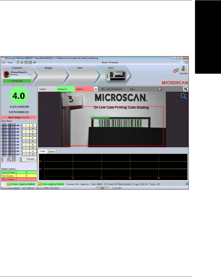
Bad Height
In this example, the software determines that the code height is too short.
Chapter 4Runtime and Job Monitoring
4-12 Getting Started with VMI
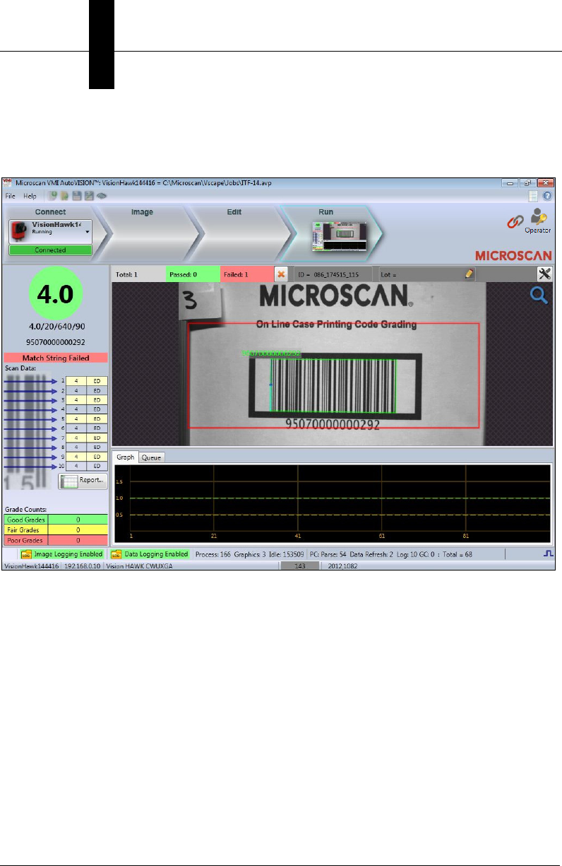
Match Failure
In this example, the symbol’s decoded data fails to match the user-defined Match String.
VMI Runtime
Runtime and Job
Monitoring
4
Getting Started with VMI 4-13
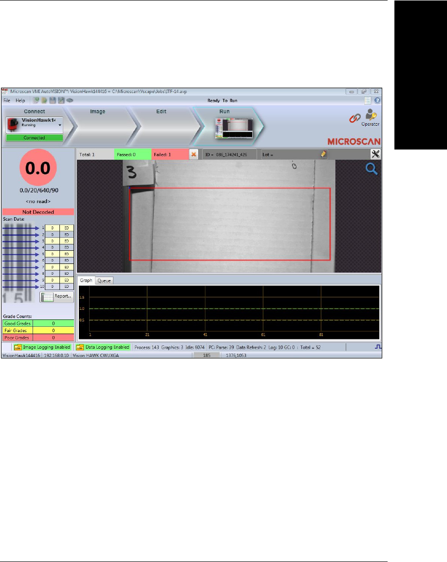
No Read
In this example, the software is unable to produce a decode because the field of view is empty.

Chapter 4Runtime and Job Monitoring
4-14 Getting Started with VMI
Example VMI Startup Process
VMI Startup
The software user interface is an integral part of the VMI solution. The Vision HAWK
Smart Camera will only go online after the PC has booted and the software interface has
connected to the camera.
PLC Communications
This example shows the communications logic of a PLC starting up and preparing to
communicate with a Vision HAWK Smart Camera.
• PLC to wait for Vision HAWK ONLINE (EIP Input Camera Status: bit 0);
• When ONLINE = True, PLC write match string to string 101;
• Wait for trigger, can monitor INSP BUSY (EIP Input Camera Status: bit 8) if desired;
• PLC monitor DATA VALID received (EIP Input Camera Status: bit 11);
• PLC retrieve results (Verification grade, Inspection Status, Barcode data, etc.);
• PLC turn ON, RESET DATA VALID (EIP Output Camera Status: bit 11) to clear DATA VALID;
• PLC turn OFF, RESET DATA VALID (EIP Output Camera Status: bit 11) to clear DATA VALID;
• Wait for next trigger, etc.
