Barcode_Basics Wp Barcode Basics
Barcode Basics Barcode_Basics Barcode_Basics industrysolutions microscan :
Barcode Basics Barcode_Basics Barcode_Basics 67fd63d2-ed24-414e-bb74-30b522616b45 _att microscan :
Barcode Basics Barcode_Basics Barcode_Basics whitepapers microscan :
Wp Barcode Basics wp_barcode_basics wp_barcode_basics whitepapers microscan :
2015-04-17
: Microscan Wp Barcode Basics wp_barcode_basics X-ModeTechnology LaunchCentral PartnerSite
Open the PDF directly: View PDF ![]() .
.
Page Count: 10

Bar Code Basics
Overview of Fixed-Mount
Bar Code Scanners
Technology White Paper

Technology White Paper
Through the years, we have found that a little up-front planning and a few simple questions can ensure a successful xed scanner ap-
plication. In contrast to hand-held scanners that have a human operator to trigger and aim the scanner, xed mount scanners require
a well thought-out plan but can deliver scales of economy if implemented correctly.
Even so, the issues and criteria involved are relatively simple. Familiarize yourself with the basics, know the right questions to ask
and don’t stop asking questions until the answers make sense.
Fixed-Mount Bar Code Scanners: Background and Applications
The earliest bar code scanners were capable of little more than rudimentary identi cation and counting tasks. By today’s standards,
they were quite cumbersome and required a great deal of human attention (and patience).
As in any rapidly evolving industry, more sophisticated technologies have proliferated as users demanded increased capability, more
power, and greater exibility to adapt to their speci c requirements. Today’s scanner marketplace offers a broad (and perhaps confus-
ing) variety of products, prices, capabilities, and levels of complexity.
During this period of rapid research, development and deployment, xed-mount scanners have emerged as superior solutions in a
wide range of installations. For a growing number of companies and applications, xed scanners have proven themselves exible, reli-
able, and economical in both the short and long term. And as the technology continues to progress, these advantages are becoming
even stronger.
Types of Fixed-Mount Scanners
In considering bar code reader applications, xed-mount scanners de nitely belong in a class by themselves. As you look more closely
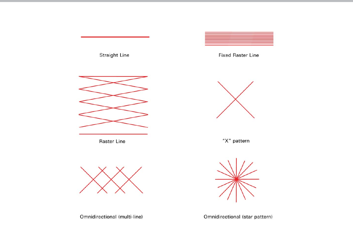
at this group, however, you’ll nd some striking differences. One of the most noticeable differences is in the scan patterns emitted.
Although the most common type of scan pattern is a straight line, other patterns include: xed raster line, moving raster, and omnidi-
rectional scanners.
At rst, many applications may seem to require a raster or omnidirectional type of scanner. While these scanners do have their own
niche in the industry, they are most often very cost-prohibitive. Both straight line and xed raster line scanners are the most economi-
cal, most exible and least complex of all xed-mount scanners available today.
Bar Code Basics: Overview of Fixed-Mount Bar Code Scanners
This white paper is intended to give you an introductory overview of fi xed-mount bar code scanners: how they work, what they can and can’t
do, and how they can meet your specifi c requirements. This paper does not attempt to make a case for any particular technology or product,
nor does it go into extreme detail about such issues as bar code label production or interface with a host computer. Topics of this paper
include:
- Fixed-Mount Bar Code Scanners: Background and Applications
- Types of Fixed-Mount Scanners
- Defi ning Your Needs
- How Fixed-Mount Scanners Work
- The Bar Code Label
- Sizing and Orienting the Label
- Label Speed and Scanner Speed
- Special Cases
- Planning Your Installation
- Optical Throw and Depth of Field
- System Considerations
- Scanner Mounting and Environment
- Terminology
Microscan Systems, Inc.
1 www.microscan.com
Technology White Paper
Defi ning Your Needs
The prospective user of a xed scanner system is in an enviable position. In most cases it is quite reasonable to insist on a system
that exactly meets your present and foreseeable needs at an affordable price. The rst step, then, is to gure out exactly what you ex-
pect the scanner system to do. Be speci c and be demanding. Remember, the scanner is working for you (not the other way around).
Once you’ve de ned your needs in your own terms, you can begin to de ne solutions in terms of the scanner. The following sections
should help you to plan your own installation, by considering such criteria as:
• How fast is the label moving past the scanner?
• How far away is the label and how much will that distance vary?
• Can the scanner read your label at the desired distance?
• How does the scanner know when to read and output the label data?
How Fixed-Mount Scanners Work
Most people who have worked in a data-collection environment have seen or used some kind of hand-held bar code scanner. Because
of this familiarity, a good place to begin discussing xed-mount scanners is to talk about how they differ from bar code “guns.”
If you’ve ever used a hand-held scanner, you recall how easy it is. You aimed the gun at the bar code, pulled the trigger, and “beep”
the read was successful. Actually, there was much more going on. First, even though you approximated an aim at the bar code before
pulling the trigger, once the red scan line appeared, you moved it until it hit the bar code. Second, once the scan line was on the bar
code, if no read occurred, you manually moved the scanner either toward or away from the bar code until a good read occurred. In
other words, you moved the scanner’s eld of vision into the area of the bar code label.
2 www.microscan.com
Types of Fixed-Mount Bar Code Scanners
Technology White Paper
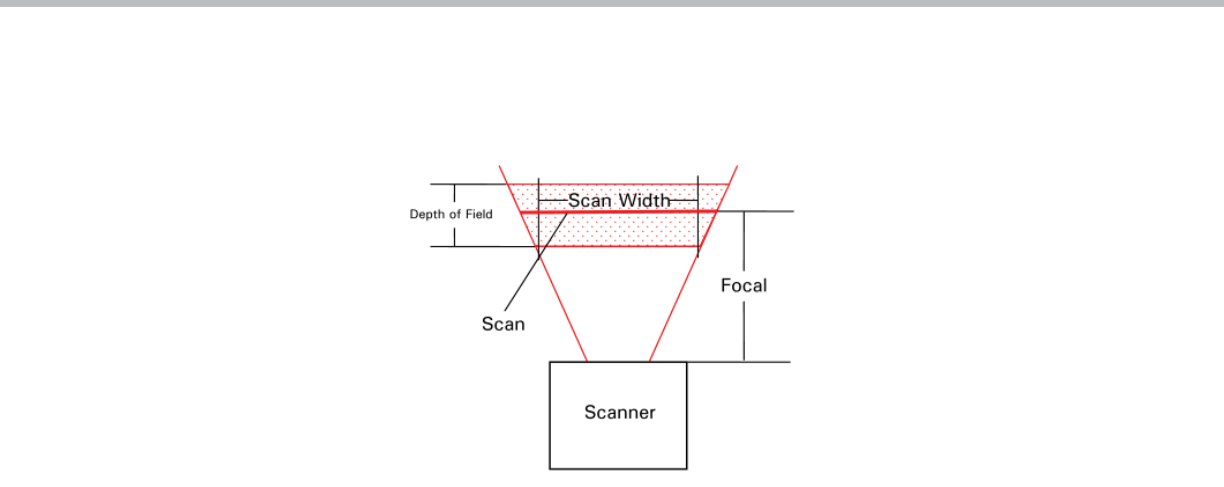
In xed-mount scanning, there’s no operator to assist the scanner, which brings us to a very important consideration: xed-mount
scanners must be positioned so that all labels passing by will appear within the “read window.” “Read window” refers to the region
within which the scanner is capable of reading bar code. The read window is de ned by the scanner’s scan width, focal distance, and
depth of eld.
The scan width is simply the distance along the scan line over which the scanner will read. This is usually less than the overall length
of the scan line due to decreased signal strength at each end of the scan line. The focal distance (also called focal point, focus, or
optical throw) is the distance between the scanner and the point upon which it is focused. Depth of eld is the region in front of and
behind the focal distance within which the scanner can still read bar code.
The focal point of a xed-mount scanner is usually speci ed by the manufacturer. The depth of eld, however, depends on both the fo-
cal point and the bar code density being used. As in photography, the greater the focal distance, the greater the depth of eld. Depth
of eld also depends on the density of bar code being read. For example, a label with narrow bars of .020 inch (low density) will have
a larger depth of eld than one with .005 inch narrow bars (high density).
Finally, not all bar code densities may be read at all focal points (just as a newspaper and a highway sign have very different optimal
reading distances). High density bar code labels require short focal distances and low density bar codes allow longer distances.
This brings up another key point about xed-mount scanning: the distance at which a scanner is required to read must be compatible
with the density of the bar code being read.
This is a very important consideration when choosing a bar code label and scanner. It is very dif cult to match a xed-mount scan-
ner with a high density bar code unless the focal distance is relatively short. If longer focal distances are required, a medium or low
density label will provide much greater exibility.
The Bar Code Label
The label itself is the most critical element in any bar code system—and the most often overlooked. Choosing the right symbology,
density, and printing method for your application will keep you from falling prey to the G-I-G-O (garbage in, garbage out) syndrome.
The rst step is to determine which symbology is appropriate for your application. There are many ne publications (such as the AIM
Auto ID Manual) which address the attributes and disadvantages of various bar code symbologies, so we won’t exhaustively duplicate
that information here. However, here are a few points to consider which should give you a good start:
• What type of bar code and printing methods are your competitors using? For strategic reasons, should you conform to a standard
(or pseudo-standard) used in your industry?
• Would anything in your installation be likely to degrade the label (cleaning solvents, heat, abrasion, airborne contaminants, etc.)?
• Be realistic about long-term label quality. For example, dot-matrix label printers require periodic ribbon changes. Could the temp-
tation to extend the time between changes jeopardize system integrity? In some installations the labels will need to be replaced
occasionally because of wear and tear, so choose labels durable enough for your application.
• If space is not at a premium, use a lower density code and a 3:1 wide-to-narrow bar ratio (the large bar is three times the width
of the narrow bar). A 3:1 ratio allows a greater margin of error in the label printing process.
• Choose labels of the right size and density.
3 www.microscan.com
The “Read Window”
Technology White Paper
Sizing and Orienting the Label
One of the most commonly asked question concerning xed-mount scanning is, “How fast can the bar code label travel?” While scan
speed is an important factor in determining this, the size and orientation of the label are equally important. In some applications, size
and orientation are dictated by the space available for the bar code (or simply by having no control over label placement). In these
cases you must simply work around the constraints, compromising where necessary.
Of course, in some applications the label will be stationary when read, so the label need only be large enough to ensure that it is
under the read window in its stationary position. However, even when the label comes to a stop when being read, it is advisable to
set up the scanner so it has a chance to read the portion of the label while it is moving. This way, even if the label is damaged, the
chances of “ nding” a readable scan are much greater. If you are required to use stationary reading, it is advisable to use a raster
line scanner thereby increasing your chances to get a read by sampling multiple areas on the label.
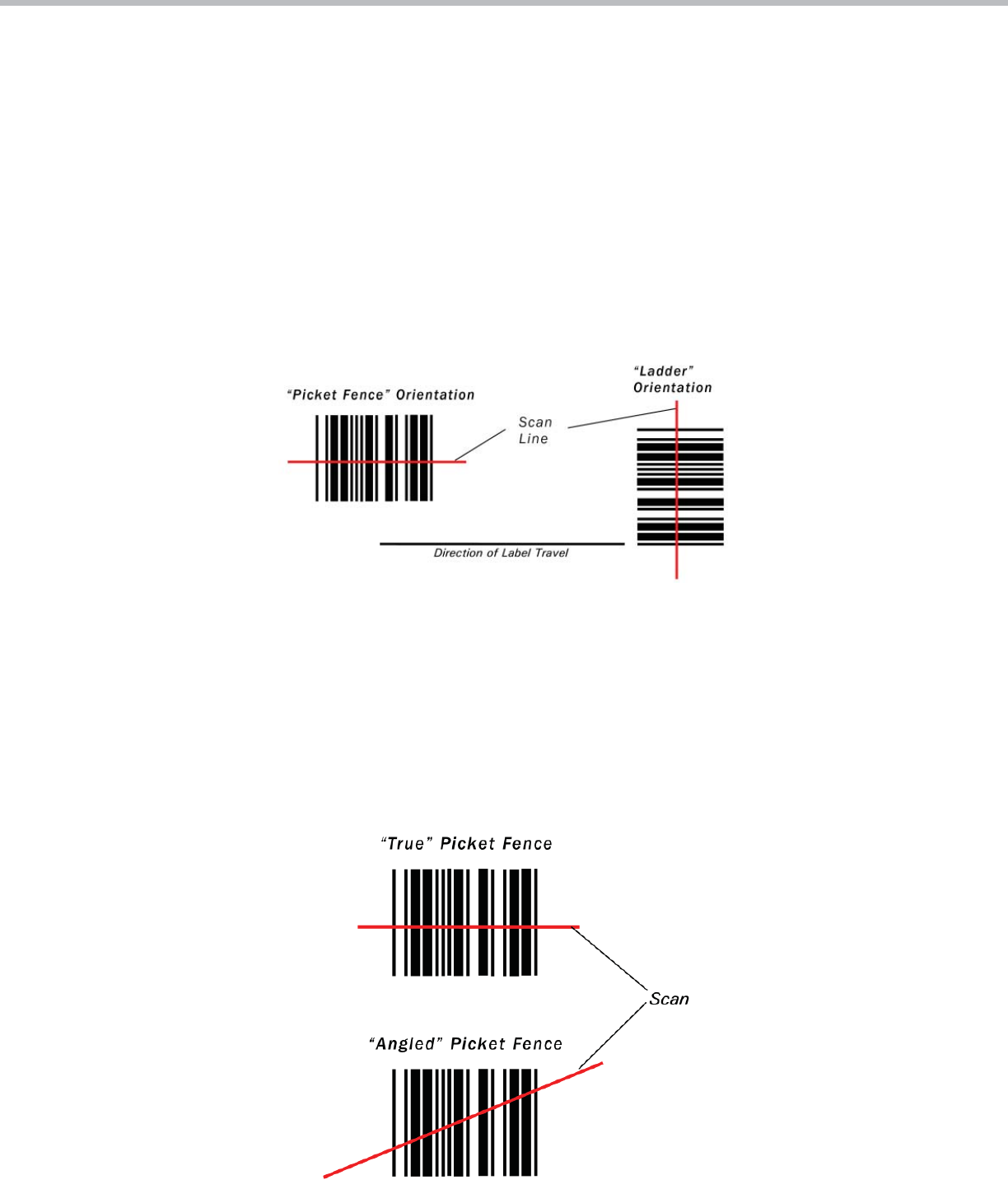
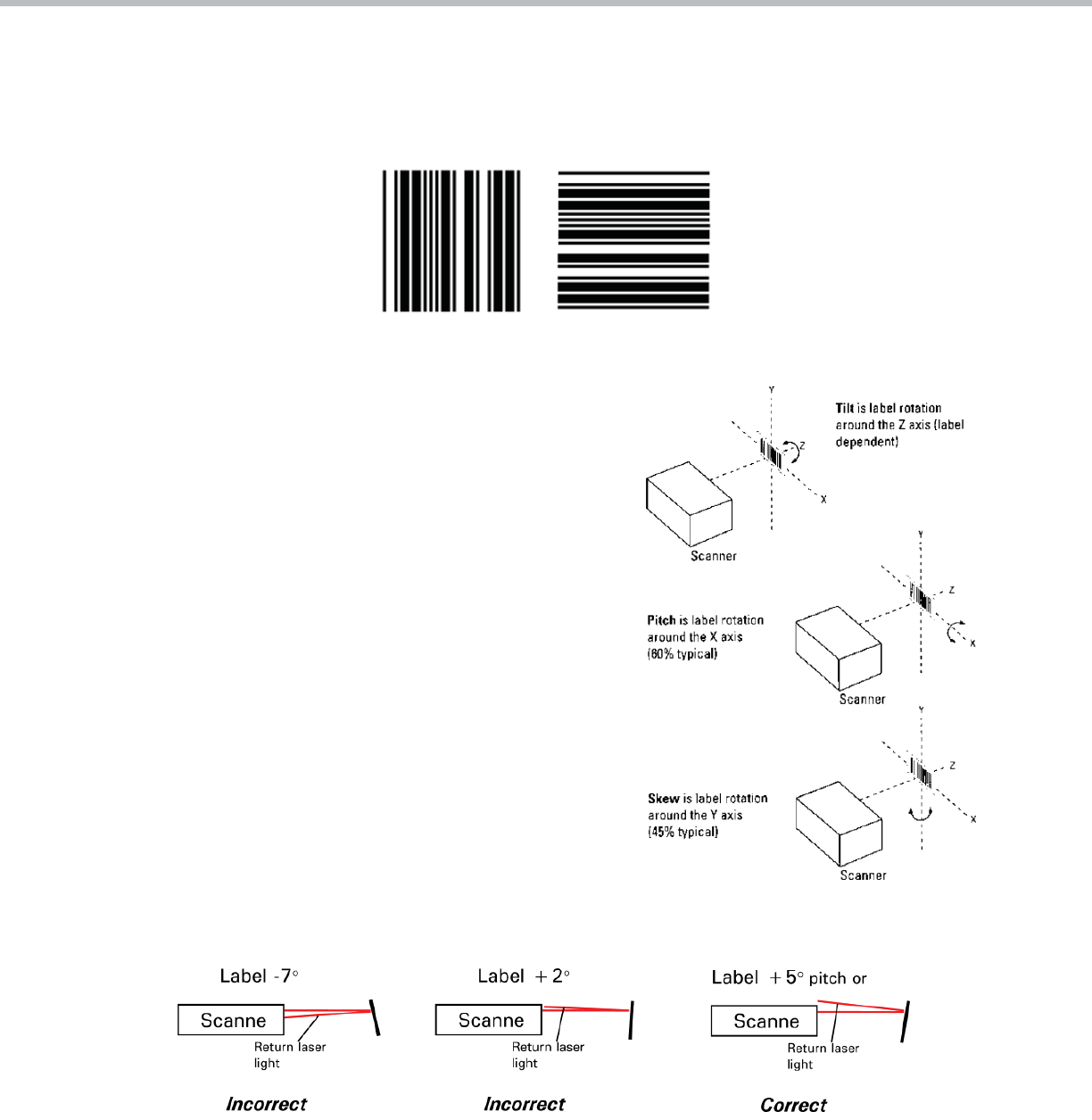
A label’s orientation is commonly referred to as either “ladder” or “picket fence.” This is a case where a picture is worth a thousand
words:
Ladder orientation
In general, if the label size and speed allow it, the ladder orientation is preferable since the scanner will be scanning different portions of
the label as it goes by. Also, label placement is not as critical. As the illustration shows, a ladder-oriented label may be successfully read
if placed anywhere within the “scan line.”
Picket- fence orientation
Unlike ladder orientation, the picket-fence orientation usually has the disadvantage of only allowing a small portion of the entire label to
be scanned. If the label is of questionable quality, or if an ink spot or void is present at the scanned portion of the label, the scanner
may not read it. In addition, label placement is critical, especially when using very narrow bar codes. Using a xed raster line scanner is
recommended because it will scan different areas of the bar code as it travels by the scanner. Another way to minimize this problem is to
use “angled” picket fence by tilting the scan line.
4 www.microscan.com

Technology White Paper
Thus you can scan a larger portion of the label and increase the label placement area by “simulating” the ladder orientation. Of course,
with a short bar code height, an angled scan line is impractical. This angled picket-fence approach is recommended only where the bar
code is reasonably tall and the label speed is not too fast in relation to the scan eld width, as angling the label will reduce the number
of scans on the label.
One advantage of picket-fence orientation can be in the area of label speed. In ladder mode, the label travel distance is the height of the
bar code. In picket fence mode, the label can be read while it travels the entire scan width. The scanner thus gets a longer look at the
bar code. The examples in the following section help to illustrate this.
Label Speed and Scanner Speed
Probably the most complicated part of a moving-beam scanner application is determining whether the scanner is fast enough to scan
a particular label reliably. Although a scanner can successfully read a bar code in two scans, experts generally recommend a mini-
mum of ve scans to read a well printed label reliably.
The following formulas are useful for calculating how many actual guaranteed scans will occur given any combination of label size,
speed, and orientation. The number of effective scans from a passing label is determined by:
• Scan rate
• Direction of label travel
• Speed at which the label passes
• Bar code label dimensions
Whether the bar code is presented to the scanner in ladder or picket-fence orientation, the number of complete scans for each pass
can be determined.
Ladder orientation
If the bar code label is presented to the scanner in a ladder orientation, the number of scans for each pass can be determined from
the following parameters:
LH = label height (inches)
LS = label speed (inches/second)
Scan rate = scans/second (speci ed by manufacturer)
The following equation is used:
The “– 2” factor in this equation is to compensate for incomplete rst and last scans. If the result of the calculations in the brackets
is 3 or more, – 2 applies. However, if it is only 2, subtract 1, giving one good scan.
Examples
LH = 0.5 inches
LS = 10 inches per second
Scan rate = 200 scans per second
Same as #1 except with scan rate = 800 scans per second
5 www.microscan.com
Technology White Paper
Picket fence orientation
If bar code labels are presented to the scanner in a picket fence orientation, the number of scans for each pass of a label can be deter-
mined from the following parameters:
LL = label length
SW = scan width (inches)
LS = label speed (inches/second)
Scan rate = scans/second (speci ed by manufacturer)
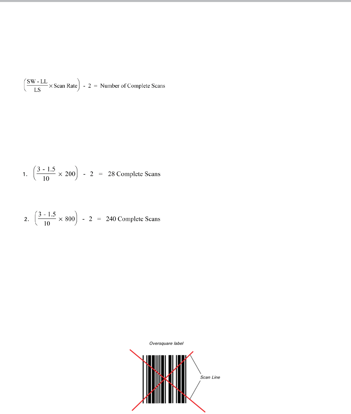
The “–2” factor in this equation is to compensate for incomplete rst and last scans. If the result of the calculations in the brackets is 3
or more, – 2 applies. However, if it is only 2, subtract 1, giving one good scan.
Examples
LL = 1.5 inches
SW = 3 inches
LS = 10 inches per second
Scan rate = 200 scans per second
Same as #1 except with scan rate = 800 scans per second
Note: The line speed or label dimension should be adjusted if the total number of complete scans is less than ve. However, with bar
code of consistently good quality, a high success is possible with as few as two scans. Also, note that these calculations must use con-
sistent units of measurement (i.e., inches and inches/second, or mm and mm/second, etc.).
Special Cases
In some cases, the application de nes whether the label orientation will be ladder or picket fence. In other cases, however, the label
may not appear in any de ned orientation. If labels are hand-applied or if the package orientation is random, the label may pass the
scanner in any orientation within a 360-degree circle. In these cases, it may be necessary to use an omnidirectional scanner, although
in some cases a less expensive raster scanner may work.
This type of application can be almost impossible to handle with a straight line or raster line scanner. However, with some exibility in
the label size, a solution can be found. If the label is oversquare, (in which the height of the bar code is greater than the length of the
bar code, including “quiet zones”), two perpendicular scan lines (forming an “X” pattern) will read it in any orientation.
6 www.microscan.com
Technology White Paper
Omnidirectional label
A similar solution is the omnidirectional airline baggage label of two perpendicular, oversquare bar codes. A single scan line will read
this label in any orientation. If label orientation cannot be controlled and the bar codes cannot be oversquare, a more expensive om-
nidirectional scanner may be needed.
Planning Your Installation
Having dealt with the bar code label, its size, and its orientation, we’re
now ready to consider it as part of the total xed-mount bar code scanner
installation. In doing so, keep the following in mind:
• Can you place the label in the ladder orientation? This orientation af-
fords more chances to read a damaged label, and label placement is
not as critical as in a picket fence orientation. In general, resort to a
picket fence setup only if the ladder mode won’t work in your
application.
• Have you avoided tilt, pitch, and skew of the label as much as
possible?
• Have you avoided the scanner’s specular re ection zone?
The specular re ection zone is a narrow zone in which direct, non-diffused
light returns to the scanner blinding the scanner and makes reading a
label impossible. This characteristic is inherent in all scanning devices
and depends mainly on label pitch relative to the scanner and label stock.
The specular re ection zone typically varies somewhere between 0° and 7°
for different scanners (0° pitch means the label is parallel to the scanner
face).
For example, if a scanner has a specular re ection zone (keep out zone) of
say 0° to +5° pitch, then mount the scanner so that there is a pitch angle
of approximately 10° between the scanner face and the label.
Optical Throw and Depth of Field
Next you must determine if the scanner can read your label at the distance you’ve chosen. Every scanner manufacturer publishes
speci cations describing these capabilities. The optimum distance (optical throw) and the difference between the nearest distance
and the farthest (depth of eld) are detailed for several different minimum-bar-width codes. As we discussed earlier, bar codes printed
with narrow bars and spaces will have shorter optical throws and smaller depths of eld.
7 www.microscan.com

Technology White Paper
The manufacturer will also specify the maximum angles of tilt, pitch, and skew allowed. Pay close attention to these speci cations and
be aware that they apply only to well printed, high-contrast labels. Eighty percent of the scanning equipment on the market today requires
at least 40 percent contrast between absolute white and black.
Finally, in any new bar code system, always try your chosen labels with the scanner you intend to use - before you install 500 scanners or
print 1,000 labels!
System Considerations
Fixed-mount bar code scanners collect data (usually on command), then either send the data to a host computer or activate an elec-
tronic signal line that causes something to happen. For accurate code/object detection, the scanner needs to be told when a label is
supposed to be read. This is accomplished when either (1) a sensor sends a signal to the scanner or (2) the host computer sends a
“read” command.
Some kind of triggering is advised because it gives the scanner an indication that it should see a bar code. Then, if no bar code is
read after a reasonable length of time (or after the bar coded item has gone away), a “no read” message is sent to the host, prompt-
ing appropriate action for a mislabeled, unreadable, or unlabeled package.
In cases where no trigger is available, the scanner can operate in a “continuous-read” mode, in which any label will be read repeat-
edly. However, in a continuous-read mode, a label could pass by without the scanner’s detecting it if it were out of the read position or
unreadable for whatever reason.
You can also choose to read continuously but only output different labels, thus getting only one output for each distinct label. You may
also incorporate time-outs with some scanners. As you can see, this can get a little complicated, so be certain to completely think
the application through (including the unexpected) before charging ahead.
Scanner Mounting and Environment
A number of factors should be taken into account when mounting xed bar code scanners. One often overlooked item is the laser
beam path itself. Some laser scanners are rated Class II visible light. This means that they have a very bright, intense beam and
should not be mounted where a worker’s eyes could encounter chronic exposure to the beam or its direct specular re ection. Most
infrared scanners are rated Class I and there is no need for such precautions, although continuous eye-beam contact is not
recommended.
The bracket for mounting the scanner should be made adjustable if possible, especially if the bar code label is small or its location
may change over time. Scanner mounting presents a number of other considerations. For example:
• Is there power available for the scanner?
• Does mounting hardware or any other object obstruct the scanner window?
• If the scanner consists of two separate units (scan head and decoder), is the distance between them within speci cation?
• Has room been left for the communication cable and connector?
• Is there re ective material or hardware around the scanner?
The environment in which the scanner will be mounted can also affect its performance. Consider the following:
• What are the shock and vibration levels, if any?
• Are there any sources of electromagnetic interference?
• Does the ambient temperature exceed the scanner rating?
• Does the ambient light exceed the scanner rating? Some pulsed infrared photo sensors can also disrupt scanner operation.
8 www.microscan.com

Technology White Paper
9
Terminology
Density—The number of narrow bars and spaces represented in the symbol divided by the total width of the symbol, usually
expressed as characters per inch.
Depth of fi eld—The region in front of and behind the focal distance within which the scanner can still read bar codes.
Focal point—The speci c measured distance between the scanner and the label at which a bar code can be optimally read.
“Ladder” label orientation—Orientation of the bar code label so that the direction of label travel is parallel to the bars and
perpendicular to the scan line.
Omnidirectional—A scanner that can read in both horizontal and vertical label positions, or any position between horizontal and
vertical.
Optical throw—The region between the scanner and the readable depth of eld.
Oversquare—A label in which the height is greater than the length.
“Picket fence” label orientation—Orientation of the bar code label so that the direction of label travel is perpendicular to the bars
and parallel to the scan line.
Pitch—The rotation of a bar code symbol about an axis perpendicular to the bars.
Raster—More than one scan line in two or more horizontal dimensions to allow reading of bar codes in different positions.
Read window—The region within which the scanner is capable of reading bar code. The read window is de ned by the scanner’s scan
width, focal point, and depth of eld.
Scan line—The beam of light that reads across the bar code for information.
Scan rate—Scanner speed, in scans per second.
Skew—The rotation of a bar code symbol about an axis parallel to the bars.
Specular refl ection zone—A narrow zone in front of the scanner in which direct, non-diffused light blinds the scanner.
Symbology—The combination of bar code characters and spaces which provide information processing for a variety of applications
and speci cations.
Tilt—Rotation of a bar code symbol about an axis perpendicular to the substrate.
Trigger—A method for informing the scanner/decoder of when to look for bar codes. This can be an external sensor device or a
host-generated signal.
©2011 Microscan Systems, Inc. 03/11
www.microscan.com
North America (Corporate Headquarters)
Email: info@microscan.com
Europe
Email: info@microscan.nl
Asia Pacifi c
Email: asia@microscan.com
