Symbol_recon_revB Wp Symbol Reconstruction
Symbol Recon symbol_recon symbol_recon 0e213893-f9e2-44ee-ab8f-92604a14d6eb _att microscan :
Symbol Recon symbol_recon symbol_recon whitepapers microscan :
Symbol Recon symbol_recon symbol_recon 0d5de643-3f20-400a-9ed1-d0375d6b5225 _att microscan :
Symbol Recon symbol_recon symbol_recon e453e872-e234-421c-b847-9d21911c588d _att microscan :
Wp Symbol Reconstruction wp_symbol_reconstruction wp_symbol_reconstruction whitepapers microscan :
2015-04-17
: Microscan Wp Symbol Reconstruction wp_symbol_reconstruction X-ModeTechnology LaunchCentral PartnerSite
Open the PDF directly: View PDF ![]() .
.
Page Count: 4

Symbol Reconstruction
in Barcoding Applications
Symbol Inconsistency
and Reconstruction Technology
Technology White Paper
Technology White Paper
Symbol Reconstruction in Barcoding Applications
This white paper discusses the challenges associated with capturing data when symbol orientation and quality can not be predicted. Ensur-
ing readability for inconsistent symbols requires the use of symbol reconstruction technology. Topics of this paper include:
- Data Capture Challenges
- Symbol Reconstruction Methodology
- Rotated Symbols
- Damaged Symbols
- Low Aspect Ratio Symbols
- Confi gurable Symbol Reconstruction Parameters
Microscan Systems, Inc.
Data Capture Challenges
Industrial environments present many data capture challenges, some of which are damaged symbols, partially covered symbols, poorly
printed symbols, and variation of label placement. Symbol quality, location, and orientation cannot always be controlled. Labels contain-
ing linear symbols (Code 39, Code 128, Interleaved 2 of 5, and UPC/EAN, for example) can be torn, partially obscured, overprinted, or
underprinted due to variations in print mechanisms. For industrial tracking and traceability to be reliable, symbols must be decoded
regardless of damage, label tilt, or any other discontinuities.
A number of industrial automation vendors have addressed the issue of symbol damage with several product introductions in recent
years. These products address the need for reliable decoding capabilities in rugged industrial settings. Recent technology, known as
barcode stitching or symbol reconstruction, among other terms, allows scanners to rebuild data from damaged or poorly positioned sym-
bols by “stepping though” the elements (bars) in multiple stages and then combining the successfully decoded regions into completed
symbol data output.
Symbol Reconstruction Methodology
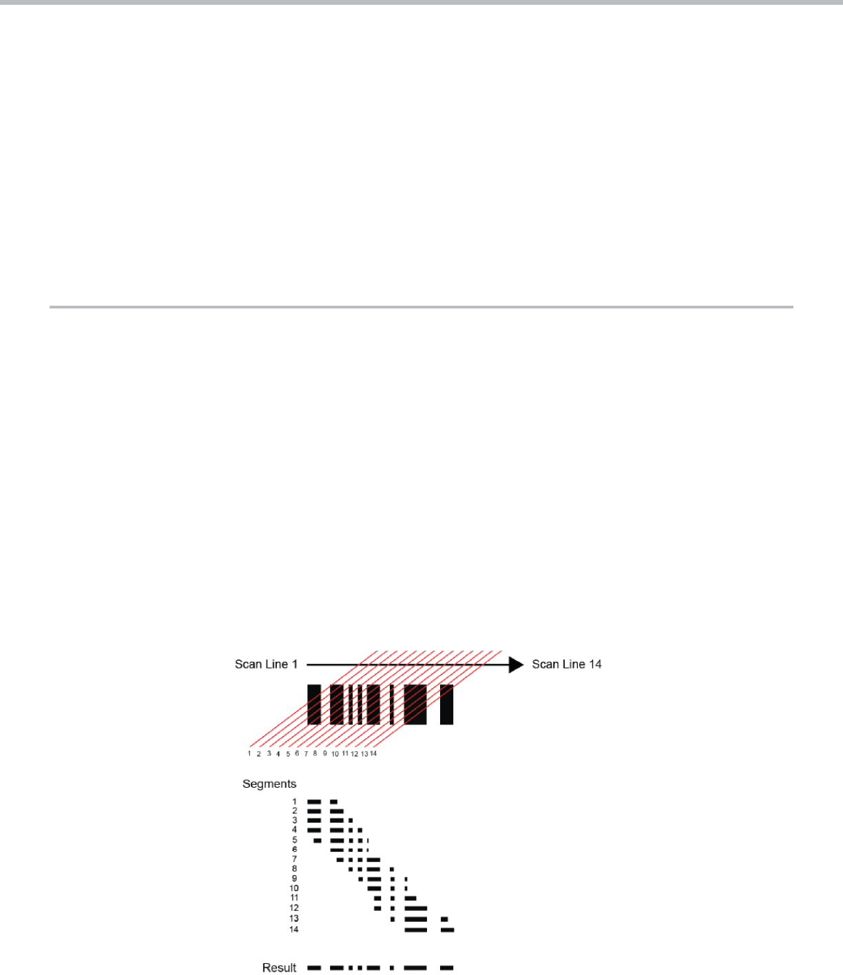
Symbol reconstruction methodology uses an algorithm that pieces together discontinuous symbol data from multiple scan lines, as
demonstrated in this simpli ed example:
Product Line Card
1 www.microscan.com
Technology White Paper
The example illustrates in very general terms how the decoding algorithm combines several incomplete segments of a rotated or dam-
aged symbol into the equivalent of a complete scan line. The data from that complete scan line is then output from the scanner to a
host system.
The illustration shows the scan lines intersecting the symbol elements (bars) at an angle, demonstrating how the algorithm reconstructs
data from tilted symbols. Reconstruction of damaged symbols is achieved similarly—by combining multiple small, undamaged and de-
codable “chunks” of symbol data into a single, continuous data string.
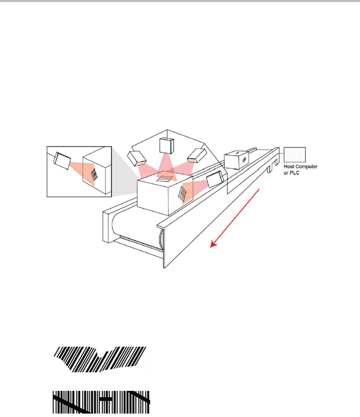
Rotated Symbols
In some packaging applications, operators may have little or no control over label placement, which can lead to unexpected symbol
orientations. Symbol reconstruction allows the scanner to decode tilted symbols that would otherwise result in No Reads. The image
below shows single-line laser scanners decoding rotated symbols. A single-line scan beam is preferable to a xed raster when perform-
ing symbol reconstruction on rotated symbols.
Damaged Symbols
Track, trace, and control applications have the potential for symbol damage as parts move through the manufacturing process. Symbol
damage can take many forms, including torn labels, eroded ink from friction or moisture, or unintended markings that partially obscure
the symbol. Symbol reconstruction algorithms are able to identify multiple undamaged areas of a symbol and then piece together those
areas to create the equivalent of a complete scan line. The complete data string from that scan line is then sent to the host.
Using symbol reconstruction technology, this Code 39 symbol with tilted and partially-
obscured elements (bars) was successfully decoded by a QX-830 laser scanner from
Microscan. The reconstruction algorithm enabled the scanner to work around the tilted
and blocked elements by combining multiple decodable segments into a complete
symbol decode.
This Code 39 symbol was also decoded by a QX-830 scanner using symbol reconstruc-
tion. The reconstruction algorithm enabled the scanner to decode the symbol as a whole,
despite the multiple locations of interference in the upper right and lower left corners of
the symbol, and the mark intersecting several of the middle bars.
2 www.microscan.com
Technology White Paper
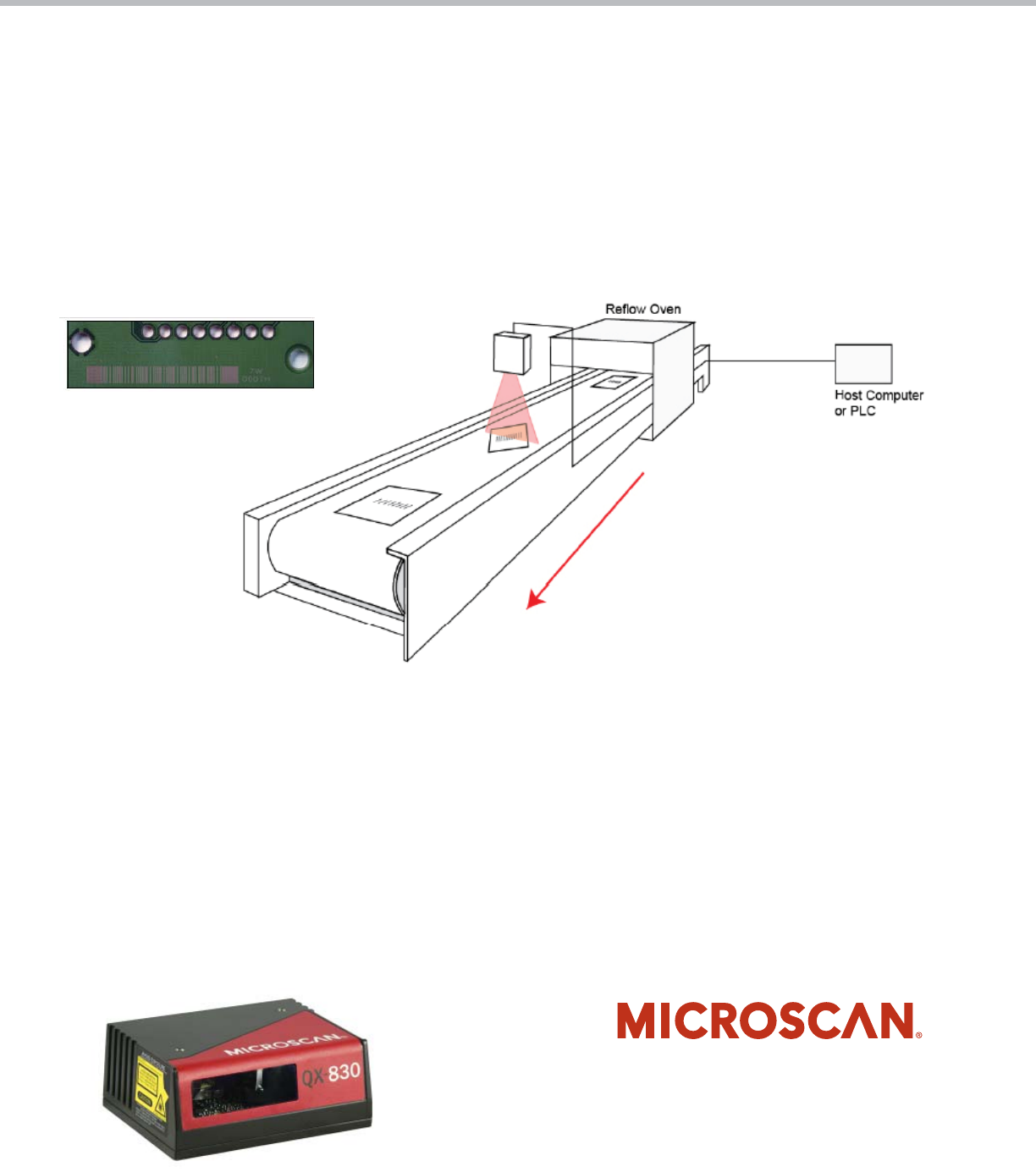
Low Aspect Ratio Symbols
Symbols with low aspect ratio are often dif cult for traditional laser scanners to decode, due in part to the fact that placement cannot
always be controlled to ensure that the scanner will be able to achieve a continuous scan line through the entire symbol. In applications
where there is little or no ability to control the rotation of symbols, a single-line laser scanner will provide the best decode performance.
In applications where control of symbol rotation is possible, a xed raster scanner will provide the best decode performance.
It is also important to note that slow-to-average line speeds (1 to 15 inches per second) offer greater exibility and reliability when
choosing the ideal laser scanner for a given application. The image below shows a laser scanner decoding a low aspect ratio symbol on
a printed circuit board in an electronics manufacturing application.
Confi gurable Symbol Reconstruction Parameters
Symbol reconstruction parameters allow the user to determine the level of redundancy (the degree of redundancy check that will be used
to qualify the reconstruction results) and effort (the amount of processing that will be applied to the reconstruction process) that will be
used by the scanner in attempting to decode a candidate symbol. The purpose of redundancy checking is to ensure that the symbol has
been decoded correctly. The redundancy check is used to qualify the result of the symbol reconstruction process. Set the redundancy to
Low, Medium, or High, depending on the quality of symbols being used in the application. If the application is using high quality symbols,
the Low setting provides satisfactory redundancy checking. A higher level of redundancy ensures greater data integrity, but may also
require a higher level of effort to decode. The purpose of the effort parameter is to determine the amount of time the system will spend
identifying candidate symbols and the amount of processing (Minimum, Medium, or Maximum effort) applied in reconstructing and de-
coding those symbols. A higher effort level may slow decode performance as the scanner runs through all options for reconstructing and
decoding the symbol.
3
©2011 Microscan Systems, Inc. 03/11
www.microscan.com
North America (Corporate Headquarters)
Email: info@microscan.com
Europe
Email: info@microscan.nl
Asia Pacifi c
Email: asia@microscan.com
