Microsoft HFW-1 Bluetooth Carkit User Manual
Microsoft Mobile Oy Bluetooth Carkit
Contents
- 1. Exhibit 8 Users Manual
- 2. Exhibit 8 Installation Instruction
Exhibit 8 Installation Instruction

CARK112
Installation Guide
Cark 112 Installation Guide 11.10.2001 10:25 Sivu 1
2
Introduction
This installation guide has been prepared to provide the basic
information necessary to install the car kit. This guide is not
intended to be definitive, because different types and models of
vehicles will require different installation work. The information
given is for general guidance only.
The terms of warranty demand that this car kit be installed by
an experienced installer and only genuine Nokia parts are
used. An end user should never attempt to install this car kit
without professional assistance as the installation requires
special tools and knowledge.
All installations should take into account any special require-
ments of the customer. However, should the customer require
an installation that is illegal or unsafe these facts must be
pointed out to the customer and a policy of non-compliance
adopted.
Please refer to the phone’s User’s Guide for instructions on the
phone’s operation, care and maintenance, including important
safety information.
Note: Read the warnings below before beginning the installa-
tion procedure.
Nokia Corporation NMP P/N 0275512 issue 1
3
WARNINGS
1. ENSURE THAT THE VEHICLE’S BATTERY IS DISCON-
NECTED BEFORE YOU START THE INSTALLATION
PROCEDURE, AND THAT IT REMAINS DISCONNECTED
DURING THE PROCEDURE.
2. DO NOT SMOKE OR USE OPEN FLAMES WHEN WORK-
ING NEAR THE VEHICLE’S FUEL SYSTEM.
3. ENSURE THAT THE VEHICLE’S ELECTRICAL CABLES,
HYDRAULIC LINES, FUEL LINES, AND SAFETY EQUIP-
MENT ARE NOT DAMAGED DURING INSTALLATION.
4. ENSURE THAT NORMAL CONTROL AND OPERATION
OF THE VEHICLE IS NOT IMPAIRED BY THE INSTAL-
LATION, PARTICULARLY THE BRAKES AND STEER-
ING. ENSURE THAT AIRBAG OPERATION IS NOT
OBSTRUCTED.
5. ELECTRONIC AND OTHER SOPHISTICATED SYSTEMS
(e.g. SPEED CONTROL, ABS ANTI-LOCK BRAKE,
FUEL INJECTION-, NAVIGATION-, AND AIR-BAG SYS-
TEMS) ARE RELATIVELY IMMUNE TO MALFUNCTION
CAUSED BY NEARBY RADIO TRANSMISSIONS. HOW
EVER, SHOULD YOU EXPERIENCE FALSE OPERA-
TION OF THESE SYSTEMS OR ARE IN ANY DOUBT
WHATSOEVER AS TO THEIR FUNCTIONALITY,
PLEASE CONSULT THE VEHICLE’S DEALER.
6. THE CAR KIT IS SUITABLE FOR USE ONLY IN VEHI-
CLES WITH A 12 V NEGATIVE GROUNDING. USE ON
OTHER SUPPLY VOLTAGES OR ALTERNATIVE
POLARITY WILL DAMAGE THE EQUIPMENT.
7. THE PHONE SHOULD NOT BE LEFT SWITCHED ON FOR
EXTENDED PERIODS WITHOUT RUNNING THE VEHI-
CLE’S ENGINE. FAILURE TO COMPLY COULD DRAIN
THE VEHICLE’S BATTERY.
4
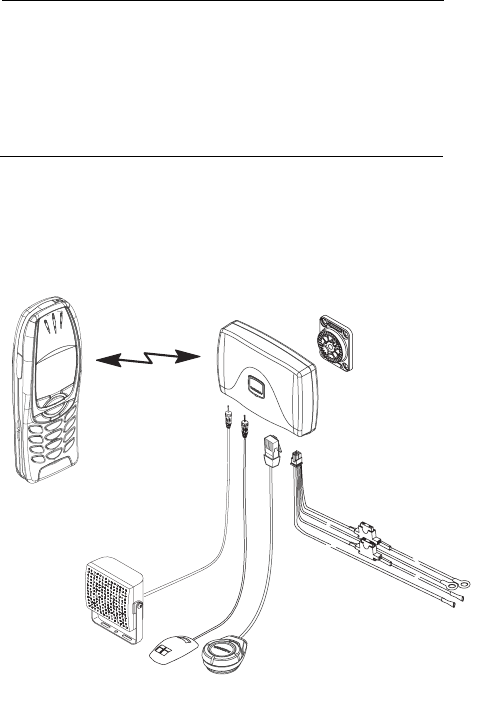
Unpacking
Carefully unpack the equipment and ensure that the following
items are present.
Wireless Hands Free Unit HFW-1
Remote Control Button CUW-2
Power Cable PCU-4
Mounting Plate MKU-1
HF Microphone HFM-8
HF Speaker HFS-12
HFW–1
HFM–8
HFS–12
PCU–4
CUW–2
MKU–1
5
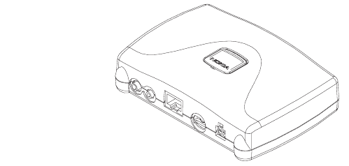
Wireless HF Unit HFW-1
The HFW-1 is used in a fixed car installation and it offers a
wireless handsfree function, a fast charging function when a
phone is connected into it by a charging cable (phone specific,
not supplied with CARK-112) and a wireless connection to
external devices.
The HFW-1 unit is attached to the vehicle interior using the
mounting plate MKU-1. HFW-1 is secured to MKU-1 with a
screw (included with MKU-1).
Power is supplied to DC socket from the vehicle’s battery via
the power cable PCU-4.
The HF microphone HFM-8, connects to the MIC socket. And
the HF speaker HFS-12, connects to the SPEAKER socket.
PHONE socket is for the charging of the phone (charging cable
phone specific - not included with car kit).
The HFW-1 is always connected to a car battery. To save the
car battery the HFW-1 goes to a sleep mode. Sleep mode is
activated if: 1. the car is not running and a phone is not con-
nected by a charging cable and there is no wireless traffic or 2.
charging of the phone has been stopped.
Installation
After tightening the MKU-1 screws, secure HFW-1 installation
to the MKU-1 mounting plate with the screw going through
HFW-1. The Nokia logo lid is placed on the HFW-1 to cover the
recess.
INTERNAL
BLUETOOTH
ANTENNA
SPEAKERMIC
REMOTE
PHONE
DC
6
Do not install the HFW-1 unit in a metal casing (or similar loca-
tion) that can prevent the unit from transmitting radio frequen-
cies. Aim the internal Bluetooth antenna (see picture) towards
the user (Bluetooth phone).
Mounting Plate MKU-1
MKU-1 is a fixed position mounting plate. It is used to attach
Wireless HF Unit (HFW-1) to the vehicle.
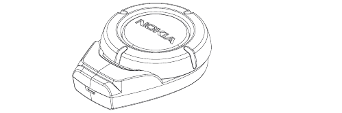
Remote Control Button CUW-2
The Remote Control Button (CUW-2) allows convenient opera-
tion of the phone. The car installation includes a Remote Con-
trol Button CUW-2, which is connected to the HFW-1 with a
cable (REMOTE socket). The speaker volume of the HFW-1
can be controlled with a ring (rotary switch) in the CUW-2. It is
possible to receive a call or to dial by pressing a send/end push
button in the CUW-2 (also voice dialing).
To read more about the use of CUW-2, see CARK112 User’s
Guide.
Installation
The positioning of the Remote Control Button CUW-2 is impor-
tant, to achieve the most comfortable position for the user. The
location of the CUW-2 should be selected so that the visibility
of the Remote Control Button is good under all lighting condi-
tions, but not so that the driver’s attention is easily distracted.
The CUW-2 should be located so that the driver can easily
reach it. Under no circumstances should the CUW-2 prevent
the driver from controlling or operating the vehicle in any way
or observing traffic.
7
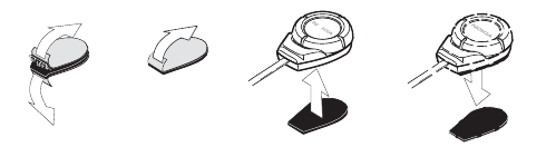
To attach the Remote Control Button:
1. Detach the two grip pads from each other.
2. Peel off the protective sheet (pad with soft fabric) from the
adhesive side and attach the pad to the desired location in the
car. Make sure the surface where you attach this pad is dry and
clean from dirt and dust.
3. Peel off the protective sheet (pad with rugged fabric) from
the adhesive side and attach the pad to the bottom of the
Remote Control Button.
4. Press the Remote Control Button against the pad in the car
until button is firmly in place.
HF Microphone HFM-8
The HF microphone should be installed according to the direc-
tions in the separate microphone installation guide. Ensure the
microphone is as close to the driver’s mouth as possible, and
attached to a surface that is mechanically quiet. The micro-
phone should be mounted at least 3 ft./1 m away from the
handsfree unit speaker to avoid acoustic feedback.
Insert the HFM-8 plug into the MIC socket in HFW-1 and twist
90° clockwise to lock firmly in place.
HF Speaker HFS-12
Install the HF speaker so that it is at least 3 ft./1 m away from
the HFM-8 microphone to avoid acoustic feedback. Insert the
HFS-12 plug into the SPEAKER socket and twist 90° clockwise
to lock firmly in place. Under no circumstances should the
HFS-12 prevent the driver from controlling or operating the
vehicle in any way or observing traffic.
1. 2. 3. 4.
8
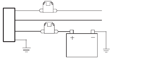
Power Cable PCU-4
The power cable connects the wireless handsfree unit HFW-1
to the vehicle’s power supply (DC socket).
The red wire must be connected to the + voltage on the vehi-
cle’s power supply via the supplied fused connector. The black
wire must be attached to a good negative GND connection.
The blue ignition sense (IGNS) wire is connected to +12 V volt-
age con trolled by the vehicle’s ignition key via the supplied
fused connector.
See section "Ignition Sense".
The yellow wire is used for car radio muting (CRM). The line
goes down to 0 volts during a call. See section "Car Radio Mut-
ing".
Cables
Ensure cables are routed as far away as possible from the
vehicle’s electronic systems (refer to WARNINGS)*. Also,
ensure that cables are not subjected to undue mechanical
stress e.g. under seats or against sharp edges.
* To prevent disturbance, cables should be routed as far away
from the interference source as possible.
Ignition Sense IGNS
The blue wire of the power cable PCU-4 is used for the ignition
sense feature. The use of ignition sense is recommended to
prevent accidental draining of the car’s battery and making the
automatic connection to the phone. The wire is connected via a
1 A fuse to a 12 volt potential that is controlled by the ignition
BLUE
YELLOW
RED
BLACK
IGNS
CRM
12V

9
key. Do not connect it directly to the high voltage sections of
the ignition circuit.
Car Radio Muting CRM
The car kit offers a feature that can mute the car radio automat-
ically during a conversation. The car radio muting feature is
based on a grounded line, so it means that in standby, the yel-
low wire (CRM) is not grounded and car radio works normally,
but during a call, line is grounded and car radio is muted.
Some radios have separate supplies for amplifiers and motors,
and another for memory backup purposes. Very often these
radios also have a secret code system, which activates itself if
a break in the memory supply is detected. Be careful when
installing the relay not to break the memory supply (usually
marked ACC or +MEM)..
Testing
Once installed, the equipment should be tested to ensure that it
is operating satisfactorily and that the position of the units does
not impair on the driver’s ability to control and operate the vehi-
cle in any way.
You can reset the car kit to the original settings, for example, to
change the default user of the car kit.
To reset the car kit: Detach the microphone cable from HFW-1
unit for less than 5 seconds. After the car kit has been reset,
the indicator light of the remote control button is shown for sev-
eral seconds.
Use the phone to make a call when the vehicle is parked with
the engine running. During the call, switch off the engine.
Ensure that the phone is operational with the engine running
and with the engine switched off.
For operating information refer to the CARK112 User’s Guide
or User’s Guide supplied with the phone.
VEHICLE
RADIO
yellow wire CRM line
HFW–1
CRM line

Nokia and Nokia Connecting People are registered trademarks of Nokia Corporation. Copyright © 2001 Nokia Corporation. All rights reserved.
Cark 112 Installation Guide 11.10.2001 10:25 Sivu 2