Microwave Radio Communications NST2G7G Microwave Mobile Transmitter User Manual NewStream User and Technical Manual
Microwave Radio Communications LLC Microwave Mobile Transmitter NewStream User and Technical Manual
UserManual.wiki
>
Microwave Radio Communications
>
NST2G7G User Manual
User Manual
Navigation menu
Upload a User Manual
Namespaces
Wiki Guide
HTML
PDF
Info
Views
User Manual
Discussion / Help
Navigation
![Page 2 NewStream User Guide and Technical ManualCopyright © 2015Part number RD001358Printed in U.S.A.Authorized EU representative: Vislink PLCQuality Certifi cation Vislink is certifi ed to ISO 9001:2008.The Vislink trademark and other trademarks are registered trademarks in the United States and/or other countries. Microsoft®, Windows®, and Internet Explorer® are registered trademarks of Microsoft Corporation in the United States and/or other countries.Proprietary Material The information and design contained within this manual was originated by and is the property of Vislink. Vislink reserves all patent proprietary design, manufacturing, reproduction use, and sales rights thereto, and to any articles disclosed therein, except to the extent rights are expressly granted to others. The foregoing does not apply to vendor proprietary parts. Vislink has made every effort to ensure the accuracy of the material contained in this manual at the time of printing. As specifi cations, equipment, and this manual are subject to change without notice, Vislink assumes no responsibility or liability whatsoever for any errors or inaccuracies that may appear in this manual or for any decisions based on its use. This manual is supplied for information purposes only and should not be construed as a commitment by Vislink. The information in this manual remains the property of Vislink and may not be used, disclosed, or reproduced in any form whatsoever, without the prior written consent of Vislink. Vislink reserves the right to make changes to equipment and specifi cations of the product described in this manual at any time without notice and without obligation to notify any person of such changes.General Safety Information The following safety requirements, as well as local site requirements and regulations, must be observed by personnel operating and maintaining the equipment covered by this manual to ensure awareness of potential hazards. This equipment has been tested and found to comply with the limits for a Class A digital device, pursuant to Part 15 of the FCC Rules. These limits are designed to provide reasonable protection against harmful interference when the equipment is operated in a commercial environment. This equipment generates, uses, and can radiate radio frequency energy. If not installed and used in accordance with the instruction manual, it may cause harmful interference to radio communications. Operation of this equipment in a residential area is likely to cause harmful interference in which case the user will be required to correct the interference at his own expense.A. The NewStream transmitter complies with Part 15 of the FCC Rules. Operation is subject to the following two conditions:[1] this device may not cause harmful interference, and [2] this device must accept any interference received, including interference that may cause undesired operation. About this Manual This manual is intended for use by qualifi ed operators, installers, and service personnel. Users of this manual should already be familiar with basic concepts of radio, video, and audio. For information about terms in this manual, see Glossary of Terms and Abbreviations [Part No. 400576-1]. Pay special attention to Notes, Cautions, and Warnings. Read NOTES for important information to assist you in using and maintaining the equipment Follow CAUTIONS to prevent damage to the equipment. Follow WARNINGS to prevent personal injury or death.](https://usermanual.wiki/Microwave-Radio-Communications/NST2G7G/User-Guide-2564620-Page-2.png)
![Page 3NewStream User Guide and Technical ManualTable of ContentsIntroduction ........................................................................................7Features ............................................................................................................... 8System Description ..........................................................................10Operational Modes ............................................................................................ 11Operating Controls .............................................................................................13Connections ......................................................................................................16IDU Local Operation ........................................................................17Changing Presets ..............................................................................................17 Preset Naming Using the Preset Display ......................................................18Changing Channels ...........................................................................................19USB Interface.....................................................................................................19Ethernet Ports ....................................................................................................19IDU Information Touchscreen ............................................................................20 IDU Information ..............................................................................................20 IDU Version .....................................................................................................21Software Upgrade Process ................................................................................22System Failure Recovery Process ....................................................................22Preset Export and Import ...................................................................................23 Export Process ...............................................................................................23 Import Process ................................................................................................24Local Microwave Control ...................................................................................26 ENG Status .....................................................................................................26Local RF Control ................................................................................................27 ENG Mode ......................................................................................................27 SNG Mode ......................................................................................................27 ODU Selection for RF Bands ..........................................................................29Local Antenna control ........................................................................................31 ENG Mode ......................................................................................................31 SNG Mode ......................................................................................................31 Alarms .............................................................................................................32 Confi guration Mode ........................................................................................33Cellular [CNG] Operation ...................................................................................33 Confi guring Cellular Communications ...........................................................34 Initial CNG Setup ............................................................................................34 Steps to Stream Video in CNG Mode: ............................................................34 CNG Touchscreens .........................................................................................36 CNG Status .....................................................................................................37NewStream Video Cellular Transmitter Data Usage .........................................38Satellite [SNG] Operation ..................................................................................39 Touchscreen Display for SNG Operation .......................................................39 Power Level Selection ....................................................................................39 Frequency Selection .......................................................................................40 Frequency 16x2 Character Display ................................................................40 Power Rocker Switch ......................................................................................40](https://usermanual.wiki/Microwave-Radio-Communications/NST2G7G/User-Guide-2564620-Page-3.png)
![Page 5NewStream User Guide and Technical ManualModify Presets Cellular Settings .....................................................81Cellular ............................................................................................................... 81Video .................................................................................................................83Encoder ..............................................................................................................83Transport Stream ...............................................................................................84Audio .................................................................................................................. 85Frequency Plans Page [CNG & ENG] .............................................86Channels ............................................................................................................ 87Confi guration Cloning .......................................................................................88 Saving Presets ...............................................................................................88 Loading ...........................................................................................................88Frequency Plans Page [SNG] .........................................................88Satellite Options .................................................................................................89Channel Number [#] ...........................................................................................90NewStream Settings Page ..............................................................91General Settings ................................................................................................91Network Confi guration .......................................................................................92Manual Mode Pages .......................................................................94License Manager Page ...................................................................95Licensed Features .............................................................................................95 ENG Modulation Features ..............................................................................95 SNG Modulation Features [Upgrade Option] .................................................95 MPEG-2 Encoder Features ............................................................................95 Encryption Features ........................................................................................95 Input Features .................................................................................................95 H.264 Encoder Features ................................................................................95Support Page ...................................................................................97System Details ...................................................................................................98 NewStream System Information .....................................................................98 Cellular ODU [CODU] System Information .....................................................98 Support Information ........................................................................................98 Restore to Snapshot .......................................................................................98Specifi cations ..................................................................................99Appendix A: Microwave and Cellular ODU Confi gurations ..........100Microwave ODU Wiring Harness .....................................................................100Microwave ODU Connection Pinouts ..............................................................101Legacy Microwave ODU Antenna Confi gurations ...........................................102NewStream Microwave ODU Antenna Confi gurations ...................................104Cellular ODU Connections ..............................................................................106 SIM Application Guide ..................................................................................106 SIM Installation Slots ....................................................................................108Cellular ODU Mounting ....................................................................................108Glossary .........................................................................................109Notes ................................................................................................................ 119Support for Your Vislink Product ....................................................120](https://usermanual.wiki/Microwave-Radio-Communications/NST2G7G/User-Guide-2564620-Page-5.png)
![Page 7AirStream User Guide and Technical ManualIntroductionNewStream is a rack-mounted microwave van transmit system designed to combine transmission technologies into a single 2 RU chassis platform. It is designed to make the gathering and transmission of news events a seamless and comprehensible task. NewStream offers multi-mode operations which can include:• ENG [Electronic News Gathering]• SNG [Satellite News Gathering (Upgrade Option)]• CNG [Cellular News Gathering (Upgrade Option)]The LiveGear Receiver [LGR-1000] is a playout device that receives NewStream IP transmissions via the Internet and provides an HD/SD-SDI output. Up to six New-Stream transmitters can be received simultaneously using one LiveGear Receiver.You can also use the VMS-1100 video media server to transcode the IP transport stream from the LiveGear Receiver for delivery to laptops, desktops, smartphones and tablets.Advanced Vislink algorithms provide effi cient, robust, and persistent video transmissions of unmatched quality. NewStream aggregates multiple 3G/4G LTE cellular channels and optimizes data throughput. This mobile unit delivers consistently smooth and dependable pictures and sound despite the occasional cellular traffi c surge or spotty signal.Leading-edge H.264 adaptive bitrate encoding technology provides remarkable video resolution with minimal latency. NewStream transmits at approximately half of the data rate required by MPEG-2 based systems. Lost or stalled data packets are seamlessly compensated for with Vislink’s exclusive predictive forward error correction algorithms. This feature provides unparalleled signal integrity throughout your entire event coverage.Figure 1: NewStream Functional Diagram](https://usermanual.wiki/Microwave-Radio-Communications/NST2G7G/User-Guide-2564620-Page-7.png)
![Page 8 NewStream User Guide and Technical ManualFeatures The award-winning NewStream system offers multi-mode operation which can include:• ENG [Electronic News Gathering]• SNG [Satellite News Gathering]• CNG [Cellular News Gathering] Transmission Integrity – Consistent Microwave, Cellular and Satellite transmission is possible using the NewStream system. Multiple aggregated 3G/4G LTE internal modems are optimized to provide regulated and consistent video transmission data throughput. NewStream utilizes up to six cellular modems to improve persistence and network diversity. Service providers may be mixed and matched to provide optimum network performance according to regional network coverage. Data rates for each modem channel are continuously adapted to meet the real-time network transfer rate. An additional modem provides Internet connectivity to communicate across all active modems. Video Quality – Effi cient adaptive bit rate algorithms maximize video data throughput producing remarkable video resolution with minimal latency in the presence of dynamic cellular network fl uctuations. HD/SD Broadcast Video Quality: User - selectable MPEG-2 4:2:2/4:2:0 [ENG/SNG] or H.264 [AVC] 4:2:0 [CNG] encoding profi les. Video Inputs for the NewStream system include composite and HD/SD-SDI video. Reliability – Using wireless 3G/4G LTE cellular, Wi-Fi satellite backhaul communication infrastructures, NewStream delivers video/audio signals when and where you want them. Power Capabilities – NewStream can operate continuously using your van’s DC-to-AC inverter outlet. Confi guration Options – Use a laptop with an Internet connection to confi gure NewStream from its Web interface. Wireless confi guration is possible using a PC, tablet or smartphone when the NewStream IDU is connected to a wireless access point. Incorporates dual mode ENG/SNG [upgrade option]: DVB-S and DVB-S2 modulation with 10 MHz high stability reference crystal oscillator. Common Multi-mode Modulator and Encoder Simplifi ed User Interface: Ergonomic programmable multi-function OLED pushbutton switches minimize front panel controller congestions. Cost effective, space saving, comprehensive multi-purpose outside broadcasting microwave transmission system. Incorporates leading-edge wireless technologies](https://usermanual.wiki/Microwave-Radio-Communications/NST2G7G/User-Guide-2564620-Page-8.png)
![Page 9NewStream User Guide and Technical ManualFeatures [continued] Compact, space-effi cient 2RU x 19” EIA all-inclusive rack mount design for ENG, CNG and SNG control [CNG and SNG are Upgrade Options]. Preserves legacy BAS ENG Van Transmission functionality: the NewStream system allows use of existing ENG Nycoil Assemblies confi gured for Type N, TNC or Triax connections. Space Effi cient ENG ODU: 2, 4, 7, 13, 2/7 GHz mast-mounted single enclosure with built-in RF coaxial relay for omni-directional antenna selection. Broadband Cellular ODU: Lightweight mast or roof-mounted cellular ODU equipped with multiple bonded cellular modems and integral high-gain broadband cellular antennas. ENG Encoding: MPEG-2, H.264 HD/SD, 4:2:2/4:2:0 CNG Encoding: H.264 AVC high-profi le @ level 4.1 adaptive bit-rate coding [ABR] encoding. [Upgrade Option] SNG Encoding: MPEG-2, H.264 HD/SD, 4:2:2/4:2:0 [Upgrade Option] ENG Modulation: COFDM [DVB-T] CNG Modulation: COFDMA, CDMA SNG Modulation: DVB-S QPSK, DVB-S2 Audio: Four embedded SDI MPEG-2 layer II and two Analog stereo pairs Access – The VMS-1100 base system transcodes and streams out to multiple-edged viewing devices such as smartphones, tablets and laptop computers. Figure 2: NewStream Outdoor Unit Application](https://usermanual.wiki/Microwave-Radio-Communications/NST2G7G/User-Guide-2564620-Page-9.png)
![Page 10NewStream User Guide and Technical ManualSystem DescriptionThe NewStream compact video transmitter system provides reliable and fl exible microwave modulation, Cellular/Wi-Fi and MPEG2,/H.264 encoding functions. The NewStream system includes an Indoor Unit [IDU] consisting of the 19-inch wide, 2-rack unit [2RU] high, rack-mounted transmitter, as shown in Figure 3, and a mast-mounted Microwave Outdoor Unit [ODU] or RF Unit [RFU]. The ODU is also known as an RF head and/or Cellular Outdoor Unit [C-ODU] on-roof mounted units.The NewStream IDU is typically mounted in a standard 19-inch [48.3 cm] rack for mobile installations and the ODU is mounted on an antenna mast. The IDU contains the baseband circuitry, power supply and control modules. It accepts a wide variety of audio and video inputs, both analog and digital and generates a 70 MHz IF for legacy heads and 950 MHz IF for NewStream heads.The IDU can be locally controlled from its front panel or remotely from a PC, tablet or smartphone over an IP connection using the NewStream’s Web browser graphical user interface [GUI].The IDU directs overall system control such as video encoding, modulation and power distribution. The NewStream transmitter supports Cellular video streaming, MPEG2 HD and SD encoding, H.264 HD/SD encoding, AES/EBU and Analog audio, ASI input and output, as well as various modulations and rates.Figure 3: NewStream Indoor UnitThe NewStream transmitter system [ENG] supports both single and dual band operation. The IDU can interact with legacy MTX ODUs or new improved performance NewStream ODUs which can be single or dual band in the same ODU housing.NewStream is a video transmission system with digital modulation capabilities which provides a sophisticated user interface with an adjustable color LCD display panel with touch screen control. An analogous Web interface enables remote control of the system.](https://usermanual.wiki/Microwave-Radio-Communications/NST2G7G/User-Guide-2564620-Page-10.png)
![Page 11 NewStream User Guide and Technical ManualA fully equipped NewStream system is High Defi nition-ready and provides a robust HD link from the fi eld to the studio with several digital video input formats accepted. In addition, NewStream accepts analog audio inputs. NewStream ODUs can be single or dual band confi gurations and come in many different RF bands. These ODUs contain integrated RF up-conversion circuitry and high power RF amplifi ers for maximum power and signal quality. With the new demands for digital modulation, the ODUs have been optimized for improved Modulation Error Ratio/Error Vector Magnitude [MER/EVM] performance with COFDM transmission.Operational ModesThe following NewStream IDU and ODU I/O connections are available:o Video and Audio:• HD/SD SDI video input. One dedicated BNC connector.• Analog composite video input. One dedicated BNC connector.• AES/EBU Audio input. Two AES/EBU channels supported through DB25 connector.• Analog Audio input. Two analog stereo pairs supported through DB25 connector.• Unbalanced 75 Ohm audio input. One AES audio supported through DB25 connector.o Transport Stream:• ASI Transport Stream MPEG2 format input. One dedicated BNC connector.o Data Interfaces: • USB interface. One USB connector on system front.• Ethernet interfaces. Total of three Ethernet RJ-45 connectors. • Serial interface. Two serial inputs/outputs supported through DB9 connector; one DB15 serial connector exclusively for Wayside Data.o ODU to IDU interfaces [one each]:• Ethernet Interface via Multimedia over Coax Alliance [MoCA] RF interfaces.• ODU 1 port provides either 950 MHz or 70 MHz depending on type of ODU [i.e. legacy or NewStream].• ODU 2 port provides 70 MHz for legacy ODU when dual band legacy ODUs are in use. Note that legacy and NewStream ODUs cannot be connected simultaneously.• Satellite Device attached to L-Band out• Test Loopback device attached to L-Band Monitor• Cellular ODU attached to Cellular ODU portNOTE: Features not implemented in the version that you have purchased are listed as upgrade options. Contact your Vislink representative for more information.](https://usermanual.wiki/Microwave-Radio-Communications/NST2G7G/User-Guide-2564620-Page-11.png)
![Page 12NewStream User Guide and Technical ManualThe ODU shown in Figure 4, performs the signal up-conversion from 70 MHz IF to RF [2 GHz or 7 GHz] and provides signal amplifi cation, as required. The NewStream IDU is typically mounted in a standard 19-inch [48.3 cm] rack for mobile installations and the ODU is mounted on an antenna mast. The IDU contains the baseband circuitry, power supply and control modules. It accepts a wide variety of audio and video inputs, both analog and digital and generates a 70 MHz IF output from the rear panel and 70 MHz IF for control of a legacy ODU. The IDU also accepts ASI from external encoders.Figure 4: NewStream System ComponentsThe IDU can be controlled locally from the front panel controls or it can be controlled remotely. The IDU can be controlled from a PC at a remote location, such as a studio, via the Google Chrome Web browser. A PC, tablet or smartphone can also be used to provide remote control of the IDU during mobile operations.](https://usermanual.wiki/Microwave-Radio-Communications/NST2G7G/User-Guide-2564620-Page-12.png)
![Page 13 NewStream User Guide and Technical ManualAll installations include an antenna, either directional, omni-directional or both. A legacy Vislink RF switch can used on the antenna mast to select the antenna required or a built-in RF switch when using NewStream ODUs can also be used. Antenna feed power and control is available at the ODU via an 8 pin circular connector. When using the mast-mounted antenna[s], a Nycoil conduit sheath covers the wiring harness between the IDU and the ODU, as shown in Figure 4. The wiring harness carries the DC power, IF control, and antenna band and polarization switching control. Additional wiring is contained in the Nycoil conduit sheath for controlling the antenna pan and tilt mechanism and for implementing additional functions such as off-air monitors, mast lights, etc.Operating ControlsAll controls are located on the front panel of the NewStream IDU. Transmitter functions are controlled using the OLED buttons and switches, as shown in Figure 5. The Liquid Crystal Display [LCD] touchscreen controls Remote/Local control, fi rmware upgrades and IP addressing of the IDU.Figure 5: NewStream IDU Front Panel Operating ControlsThe LCD with touch screen, buttons and function keys are used to select control and diagnostic menu screens for both the IDU and the ODU. Option buttons displayed on the LCD are used to control Preset selection, RF band selection, channel selection, antenna selection, antenna polarization, transmitter operation, power [low, high or adjustable], and to monitor the status of the IDU and ODU. The option buttons displayed on the LCD may be selected using either the color LCD display panel touch screen or the function keys. Table 1 lists the functions and displays of the controls. NOTE: When the IDU is shut down all the component variables are saved at the last state with which the IDU was confi gured. The exceptions to this are the following states: Microwave Power Amplifi er, Satellite RF Carrier and Cellular Cell Transmit which always default to Off on IDU powerup.](https://usermanual.wiki/Microwave-Radio-Communications/NST2G7G/User-Guide-2564620-Page-13.png)
![Page 14NewStream User Guide and Technical ManualControl/Connection Type Button Text FunctionsA: Liquid Crystal DisplayCapacitive Touch TFT 5 in. [diag.] display n/aThis LCD displays:• confi dence video monitor;• alarm & status information;• microwave & satellite RF Power readout;• setup screens to confi gure IP address, local / remote mode and fi rmware updatesB: RF Power Adjust Rocker Switch n/aThe Microwave Mode rocker switch allows:• adjustment of Radio Frequency Power up & down.The Satellite Mode rocker switch allows:• adjustment of L-Band Power up & down.C: Microwave/Satellite SwitchOLED Multi-function Pushbutton SwitchPA HIPA LOWMOD ONMOD OFFThe Microwave button allows:• setting of RF Power to High, Low • indicates PA ADJ [i.e. ADJ = Adjustable] mode.The Satellite Mode button allows:• setting of state change of Modulation to on or off.D: Microwave/Satellite Switch OLED Multi-function Pushbutton SwitchPA ONPA OFFCW ONCW OFFThe Microwave Mode button allows:• setting of Power Amplifi er to on or off.The Satellite Mode button allows:• setting of RF Carrier on or off.E: Frequency Display 16x2 OLED Display n/aThe FREQUENCY display shows:• active frequency & channel number;• allows scrolling through pre-stored frequency & channel plan [using rocker switch G].F: Preset Display 16x2 OLED Display n/aThe PRESET display shows:• active preset name & number and operating mode;• allows scrolling through pre-stored presets or operating modes [using rocker switch H].G: Frequency Selection Rocker Switch n/a This switch allows scrolling through a pre-stored frequency & channel plan.H: Preset Selection Rocker Switch n/a This switch allows scrolling through pre-stored presets or operating modesI: Enter Frequency Illuminated Pushbutton Enter Switch n/a This button provides a means to select a new frequency.J: Enter Preset Illuminated Pushbutton Enter Switch n/a This button provides a means to select a new preset value.K: Antenna Polarity Selection Switch OLED Multi-function Pushbutton SwitchPol V Pol HPol RCPol LCThe Antenna Polarity [Pol] selection button:• V - sets Vertical Antenna Polarity; • H - sets Horizontal Antenna Polarity;• RC - sets Right Circular Antenna Polarity;• LC - sets Left Circular Antenna Polarity.L: Antenna Selection Switch OLED Multi-function Pushbutton SwitchANT 1ANT 2The Antenna selection button:• ANT 1 - selects Antenna 1; • ANT 2 - selects Antenna 2.Table 1: NewStream Front Panel Operating Controls & Connections](https://usermanual.wiki/Microwave-Radio-Communications/NST2G7G/User-Guide-2564620-Page-14.png)
![Page 15NewStream User Guide and Technical ManualControl/Connection Type Button Text FunctionsM: RF Band Selection Switch OLED Multi-function Pushbutton SwitchIndicates the current bandThe RF Band selection button:This band depends upon the type of ODU that is connected.N: Cellular Control LED Indicators n/aThese indicators display the status of the transmission strength of the six cellular modems. The LEDs are lit:• green to indicate LTE/4G cellular transmission, which is the optimum;O: Start or Stop Cellular TransmissionIlluminated Pushbutton Enter Switchn/aThis button provides a means to start or stop cellular transmission. This button also indicates:• when lit - Cellular modems are transmitting &• when unlit - Cellular modems are in stand-by mode.P: ON/OFF: Rocker Style Power Switch n/a This button applies or removes power to the NewStream transmitter. Q: ETHERNET Port Ethernet connection plug n/aThis port provides a connection to access a Web browser via a PC or mobile device for setup control & monitoring.R: USB Port USB connection plug n/aThe USB Connector provides a connection to upgrade system fi rmware. Table 1: NewStream Operating Controls & Connections [continued]](https://usermanual.wiki/Microwave-Radio-Communications/NST2G7G/User-Guide-2564620-Page-15.png)
![Page 16NewStream User Guide and Technical ManualEthernet I/OASI InputComposite Video Digital Audio BalancedSD or HD SDI InputCellular ODU I/OAnalog Audio InputsAntenna Polarization ControlConnections Connections to the NewStream transmitter are shown in the illustration below. The Video input BNC connector, external antenna, power switch and SIM slots are located on the right side of NewStream.Control Data Serial PortUnbalancedMicrowave ODU VoltageMicrowave ODU1 IF Output [NewStream ODU or 1st legacy MTX ODU]Microwave ODU2 IF Output [2nd legacy MTX ODU]L-Band Out - to SNG equipmentASI OutputWi-Fi SMA [future option]AC Power Supply Input & Circuit BreakerFigure 6: NewStream IDU Rear Panel Connections/ControlsL-Band MonitorODU Model - Do not switch until ODUs are powered down - see Warning in ODU Selection for RF Bands section.](https://usermanual.wiki/Microwave-Radio-Communications/NST2G7G/User-Guide-2564620-Page-16.png)
![Page 17 NewStream User Guide and Technical ManualIDU Local OperationThe NewStream IDU front panel provides monitoring and control of the entire system. The Liquid Crystal Display [LCD] touchscreen provides menu screens for the set-up, control and diagnostic status of both the IDU and ODU [see Figure 5 item A]. The LCD also provides a preview monitor of the source video that is being transmitted by ENG, SNG or CNG. If you are not in a sub-menu, the preview video is displayed. If there is no video feed, the screen is blank. To change the control from Remote to Local, use the Confi guration Mode touchscreen, and example of which is shown in Figure 20. In addition to the main control LCD there are presets and frequency displays where current preset mode and operation frequency are presented. Dedicated Organic Light-Emitting Diode [OLED] buttons, rocker switches and lighted Enter buttons allow for modifi cation of preset and frequency [see Figure 5 items E, F, G, H, I and J].You can interact with the system via the touchscreen display or through function keys. The front panel control display can be used for local control. The Web interface also allows remote control of NewStream. Local control is preferred by operators who do not want others to reconfi gure NewStream while they are controlling it; the LCD provides a means to set local control. You can always use the Web interface to access information and to determine status of NewStream, even when the operator has the IDU in local mode. The Web interface is available for control of NewStream only when it has been set to remote control by the local operator. For quick system setup, dedicated controls exist on the front panel such as: preset selection, operating frequency selection and ODU controls. When you press the On/Off button on the front of NewStream [see Figure 5 item P], NewStream begins the boot up process. This process starts with the On/Off button illuminating green and the touchscreen displaying a Vislink logo. The start up time is approximately 40-45 seconds. Once NewStream is fully booted up, the touchscreen displays the video preview, as well as the status indicators. The OLED buttons and 16x2 Frequency and Preset indicators [see Figure 5 items E and F] display the last state confi gured, except for the buttons that control RF power, which are automatically set to Off upon applying power to the transmitter, and for any major operational change to the system including preset change, frequency change, and band change.Changing PresetsThere are three factory installed presets that you can use to begin operating NewStream. The 16x2 Preset display [see Figure 5 item F] allows you to scroll through the list of loaded presets via the rocker switch [see Figure 5 item H]. The rocker switch always increments the preset number. If you continue to press the switch to the end of the list in one direction, the list wraps around and starts again as you continue pressing the rocker switch. As you scroll through the preset list and select a valid preset, by pressing the Set Preset [Enter] indicator button [see Figure 5 item J], the Enter button begins blinking amber. If an invalid preset is selected due, for instance, to not having the proper modules or license installed in NewStream, then the Set Preset Enter button is lit red.](https://usermanual.wiki/Microwave-Radio-Communications/NST2G7G/User-Guide-2564620-Page-17.png)
![Page 18 NewStream User Guide and Technical ManualWhen you locate the preset that you want to load, press the blinking Enter Preset button [Figure 5 item J]. This action automatically turns off any NewStream RF transmitting device [for example: PA On, Carrier On or Cellular On]. The Enter button will not be illuminated indicating that the NewStream operating system has begun loading the selected preset. Once the preset has been loaded, the Enter button is lit green, indicating that the preset is operating normally. The 16x2 Preset display also shows the preset that you have selected. Note that the preset loading state may last ten or more seconds if you are switching from one operating mode to another [for example ENG to SNG].The top line of the Preset 16x2 display presents PRESET, the preset’s number [1-99] and the mode of operation. The second line displays The name that you have assigned it up to 16 characters. If the name is greater than 16 characters, the display will scroll through the entire name and then revert back to the fi rst 16 characters, providing the ability to ensure that the correct preset has been selected.Preset Naming Using the Preset Display • ENG and SNG cannot be used at the same time therefore only one active ENG or SNG preset is valid.• CNG mode can be used simultaneously with ENG / SNG or independently.• Each preset name displays a prefi x of one of the following types:o ENG – indicating microwave preset capabilityo SNG – indicating satellite preset capabilityo CNG – indicating cellular preset capabilityo ENG/CNG – indicating simultaneous microwave and cellular operationo SNG/CNG – indicating simultaneous satellite and cellular operationo MANUAL – indicates that NewStream is not operating in a preset mode. Manual mode can be employed when an operator wants to test a setting without modifying an existing preset.Preset names can be duplicated in the radio, however NewStream differentiates presets by the index number. It is not recommended to duplicate preset names since it can cause issues with preset reordering. Up to 99 presets can be saved on NewStream. The fi rst line of the character display shows one of the 6 preset prefi xes followed by the preset number. If the mode is manual, then the preset number is not displayed. The second line of the character display shows the preset name, or it shows No Preset if you are in Manual Mode.](https://usermanual.wiki/Microwave-Radio-Communications/NST2G7G/User-Guide-2564620-Page-18.png)
![Page 19Changing ChannelsThe 16x2 Frequency display presents the current Channel number on the top line, as well as the frequency of the channel on the bottom line [see Figure 5 item E]. The available Channel selection depends on the type of ODU and preset selected [ENG vs SNG]. Refer to the Change ODU [RF Bands] section to learn how frequency bands are selected, and Change Preset to determine how presets are changed.You can scroll through the available channels in this frequency mapping for this particular frequency and ENG or SNG mode via the rocker switch [see Figure 5 item G]. The rocker increments the channel number. If you press the rocker switch until the end of the list in one direction, the list starts again. The Enter channel button will blink amber when viewing a channel that is different from the currently active channel.Press the blinking Enter Channel button when you locate the desired channel [see Figure 5 item I]. This will automatically turn off any RF transmitting device in NewStream [PA on, Carrier on or Cellular On]. The button is lit green to indicate that NewStream accepted the state change and is operating correctly. The 16x2 Frequency display presents a message: Channel Loading on the fi rst line and Please Wait on the second line.Once the channel has been loaded, the amber button is lit green. The 16x2 Frequency display presents the channel that you selected. Should the channel not be set, the Enter channel button will blink red for 5 seconds and then stays red and an alarm will indicate that there was a problem with the channel selection.USB InterfaceThe USB interface [see Figure 5 item Q] provides a connection to upgrade system fi rmware. Refer to Software Upgrade Process for more information. You have the option of recovering your NewStream system using the USB port to activate System Failure Recovery. See the System Failure Recovery Process for details. You may also use this port to export presets. Refer to Modify Presets for more details.Ethernet PortsThe Ethernet ports provide to access a Web browser via a PC [or mobile devices] for setup control and monitoring [see Figure 5 item R and Figure 6 (Ethernet I/O)]. There is an RJ-45 port on the front panel and two RJ-45 Ethernet connectors on the rear. Any of these three RJ-45 connections can be used to access NewStream’s Web interface.NewStream User Guide and Technical Manual](https://usermanual.wiki/Microwave-Radio-Communications/NST2G7G/User-Guide-2564620-Page-19.png)
![Page 20NewStream User Guide and Technical ManualIDU Information TouchscreenIDU Information The IDU Network Settings touchscreen displays the following information:• IP Allocation [Static or Dynamic]• IP Address• Subnet• Gateway• DNSFor further information about the listed settings, refer to the NewStream Settings Web interface section. Refer below to Figure 7 for the IDU Network Information and the Numeric Entry Pad that appears when you press the entry fi elds. Swipe to the right on the touchscreen to display the IDU Version screen.Figure 7: NewStream IDU Information Touchscreen - Network Settings & Numeric Entry Pad](https://usermanual.wiki/Microwave-Radio-Communications/NST2G7G/User-Guide-2564620-Page-20.png)
![Page 21 NewStream User Guide and Technical ManualFigure 8: NewStream IDU Information Touchscreen - Software Version & UpgradeIDU VersionThe IDU Software Version and Update touchscreen displays the following information:• Current IDU software version• Update option [press the Begin button to initiate upgrade]Both pages can be viewed by swiping the screen and observing the placement of the scroll bar at the bottom of the IDU Information touchscreen, as shown in Figures 7 and 8.](https://usermanual.wiki/Microwave-Radio-Communications/NST2G7G/User-Guide-2564620-Page-21.png)
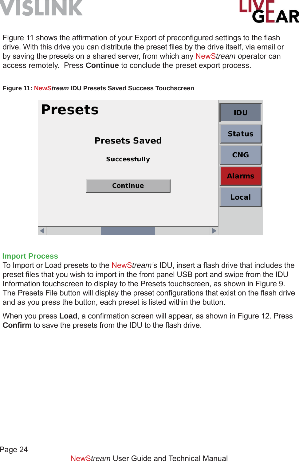
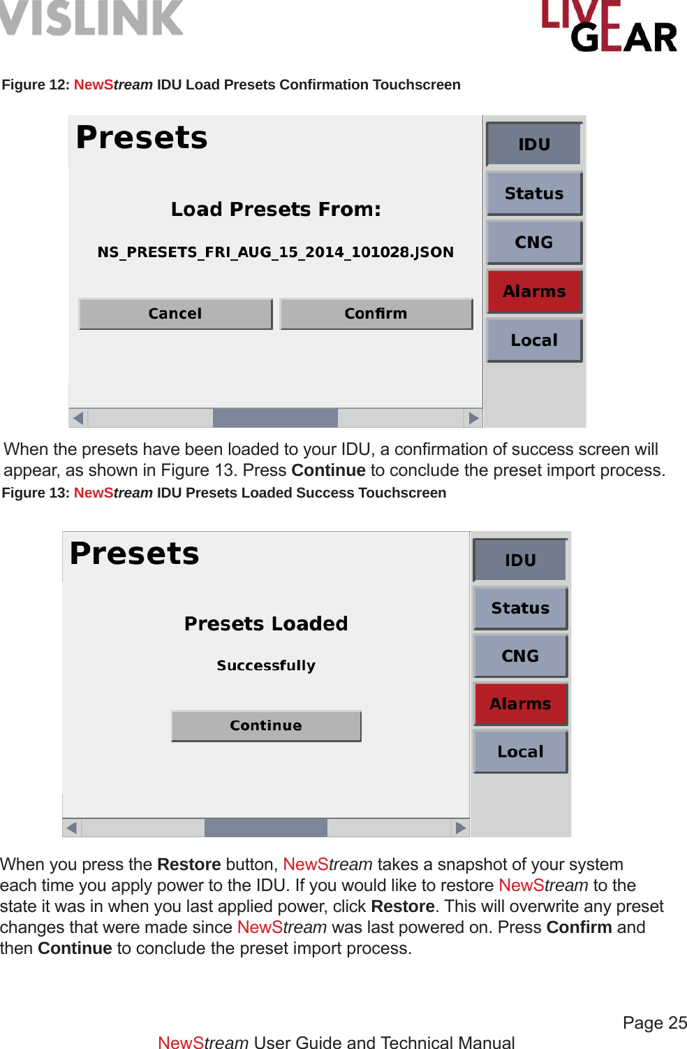
![NewStream User Guide and Technical ManualSoftware Upgrade ProcessThe following procedure must be strictly adhered to when you are issued an upgrade for the latest fi rmware.1. Copy NewStream software fi le [.nsu fi le type] to the root of a partitioned USB fl ash drive [data stick]. 2. Insert the fl ash drive in the USB port on NewStream’s front panel 3. Press the IDU button on NewStream’s touchscreen and swipe to the IDU Version touchscreen [refer to Figure 8].4. Press the Update File fi eld until the most current version of NewStream’s software is displayed.5. Press the Update button to start the upgrade.6. Press Confi rm if the version shown in the Update File entry fi eld is correct.7. Next, observe that NewStream’s Logo appears with an Upgrading Software message.8. Do not remove the USB fl ash drive until the Update Complete message is displayed. NewStream will restart automatically.9. Allow this process to repeat and check that the ODU upgrade .nsu is shown in the Update File fi eld, should you also be updating the Cellular ODU. NOTE: When upgrading NewStream software, you must use the USB fl ash drive and front panel operation. While the software upgrade occurs, the IDU front panel OLED buttons and 16x2 Frequency and Preset displays will be unlit and the touchscreen will display the message: Software Update In progress, DO NOT POWER-OFF.System Failure Recovery ProcessIf NewStream refuse to restart, the following process can be used to recover system functionality.1. Copy NewStream software fi le [recovery.nsu fi le] to the root of a partitioned USB fl ash drive. It will be the only fi le at the drive root.2. Insert the USB drive into the front panel port and apply power to the IDU. 3. Press buttons K: Antenna Polarity Selection Switch and M: RF Band Selection Switch simultaneously and hold for at least 5 seconds [refer to Figure 5]. Wait until the System Recovery Mode: Upgrading Software message is displayed on the touchscreen.4. Insert the fl ash drive and wait for at least 30 seconds. System Recovery Mode: Upgrading Software message will be displayed.5. Next, observe that NewStream’s Logo page appears with an Upgrading Software message.6. Do not remove the USB fl ash drive until the Update Complete message is displayed. NewStream will restart automatically.Page 22](https://usermanual.wiki/Microwave-Radio-Communications/NST2G7G/User-Guide-2564620-Page-22.png)
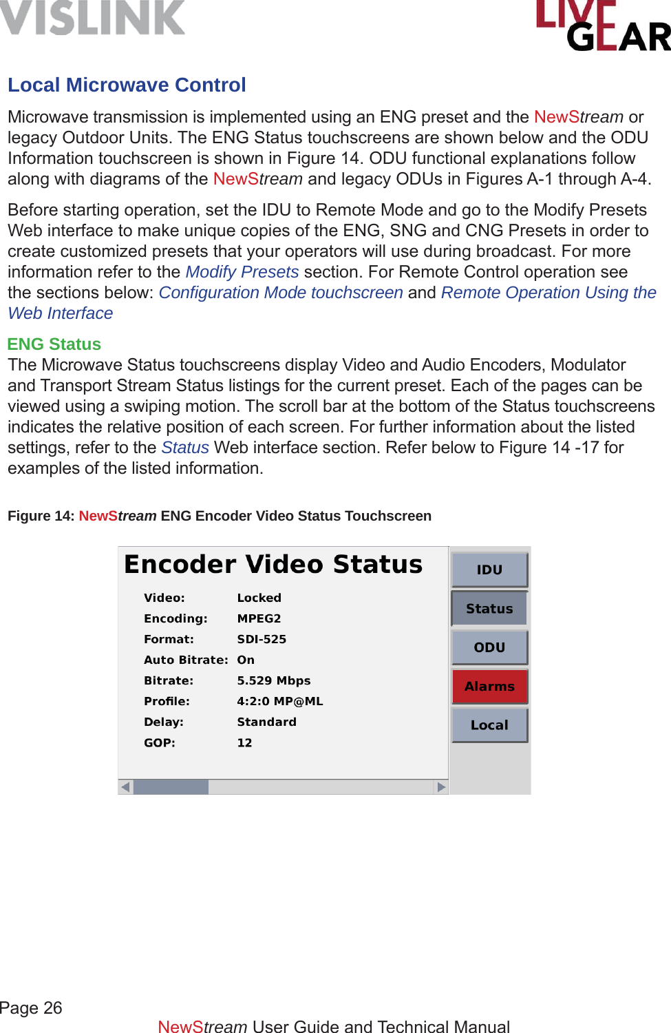
![Page 27NewStream User Guide and Technical ManualLocal RF ControlThere are two OLED buttons and one set of rocker switches that control Radio Frequency functionality [see Figure 5 items C and D]. ENG ModeThe upper RF Control OLED button is used to control the Power Amplifi er functionality [see Figure 5 item D]. This button toggles between PA ON to PA OFF. When you press this button, it will show inverted colors until the operation is complete. Should the action take a few seconds to resolve, you have positive acknowledgment that NewStream received input and is loading the state change request. PA ON will display a blue background allowing you to see this indicator at a distance without having to be close enough to read the text.The lower OLED button toggles between PA HI and PA LO [see Figure 5 item C]. The last state of this button is restored upon system shutdown and startup. Pressing the rocker up or rocker down button under the PA HI/PA LO OLED will put NewStream into PA ADJ mode [see Figure 5 item B]. The power level of PA ADJ will default to full power [zero attenuation] if PA ADJ has not been selected for this ODU Band before, but otherwise entering PA ADJ will recall the last adjustable power setting for this ODU Band. The PA ADJ state for dual band ODUs [i.e. 2/7 GHz] may display different RF level readings as the adjustment for each RF band, either 2 GHz or 7 GHz, is independent of one another. This will cause the bottom OLED to show PA ADJ [see Figure 5 item B], and will allow the up/down rocker to adjust PA power. While in PA ADJ, pressing the bottom OLED will take the system out of PA ADJ mode, and put it into the last power state. SNG ModeThe upper OLED button is used to control the Satellite Carrier functionality [Figure 5 item D]. This button toggles between Carrier enabled [CW ON] and CW OFF. When you press this button, it will show inverted colors until the operation is fi nished. Similarly, the lower OLED button [see Figure 5 item C] toggles between Modulation disabled, MOD OFF and enabled, MOD ON. Both the OLED button’s default states are OFF.](https://usermanual.wiki/Microwave-Radio-Communications/NST2G7G/User-Guide-2564620-Page-27.png)
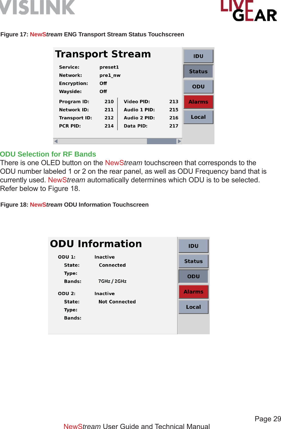
![Page 30NewStream User Guide and Technical ManualThe ODU button allows you to view with which RF ODU NewStream is communicating. There are a few confi gurations of ODUs which can be selectable. A rear panel ODU switch is provided to set the NewStream IDU to the correct voltage and IF to communicate with either legacy [MTX 12V] or NewStream ODU [NST 48V] type. You cannot hook up multiple NewStream ODUs to the NewStream IDU. WARNING: If the ODU the switch is placed in the wrong position or if you change the ODU type without changing the switch position and restart the IDU this may result in damage to the ODU and inability to communicate with the ODU.Toggle Mode RF Band Button BehaviorIf the toggle switch is in NewStream ODU mode [NST 48V], and the NewStream ODU is dual band, the RF Band button can be used to specify which band is currently selected. The button shows the RF Band covered by the current selection [2 GHz, 4 Ghz, 7L GHz, 7U GHz, 13 GHz]. If the toggle switch is in NewStream ODU mode and the NewStream ODU is single band, the RF Band only displays the status of the RF band and will not act as a selection button. The button shows the RF Band covered by the current selection [2 GHz, 4 Ghz, 7L GHz, 7U GHz, 13 GHz]. If no ODU is currently detected, then RF Band button displays NO ODU.Legacy Toggle Mode RF Band Button BehaviorIf the toggle switch is in Legacy ODU mode [MTX 12 V], the RF Band button alternates between using ODU 1 and ODU 2 outputs on the back of the IDU, regardless of which ODUs are connected to those ports. When ODU 1 is selected, 70 MHz IF and FSK is be directed to the ODU1 port, and 12 V is sent to ODU 1 power connector. When ODU 2 is selected, 70 MHz IF and FSK is directed to ODU 2 port, and 12 V is sent to ODU 2 power connector. If an ODU is disconnected, NO ODU is shown in the OLED button, the 16x2 Frequency display is unlit, the button next to it is lit red, and an alarm displays. If the ODU is reconnected, the state of the IDU resumes operations. Pressing the PA Band button switches to the other available ODU port however, the disconnected ODU is not be selectable. The RF Band button displays the ODU the RF Band covered by the current selection on the bottom line [2GHz, 4Ghz, 7L GHz, 7U GHz, 13GHz]. The 16x2 Frequency also displays the frequency band. If both ODUs are the same head type and frequency band, the RF Band button toggles between ODU 1 and ODU 2 ports but displays the same band information on the button. If no ODU is currently detected, then the RF Band button displays NO ODU.](https://usermanual.wiki/Microwave-Radio-Communications/NST2G7G/User-Guide-2564620-Page-30.png)
![Page 31 NewStream User Guide and Technical ManualODU Disconnect/Reconnect During OperationThe NewStream IDU always monitors the connection between itself and the ODU on the selected port. NewStream automatically detects whether the connection is lost between IDU and ODU within 15 seconds. If connection loss is detected, an alarm displays in the alarm indicator, the RF Band button displays NO ODU, and the 16x2 Frequency display is unlit and the selection LED button is lit red. In case of a disconnect, the IDU continues to search within the current port for the ODU. If the ODU connection is re-established, then the previous alarm will clear, and the RF Band button will show the RF band of the ODU connected. The 16x2 Frequency display presents the frequencies supported by the head. In the case of multiple bands included within the ODU, the IDU will set the ODU to the band selected before the ODU was disconnected. Local Antenna controlENG ModeThe upper Antenna Control OLED button controls Antenna Polarity [see Figure 5 item K]. This button cycles between vertical [V], horizontal [H], right-hand circular [RC] and left-hand circular [LC] polarization. There is minimal delay between switching from one polarity state to another. The middle OLED button controls a relay to switch between Antenna 1 and Antenna 2. There should not be any delay between switching from one Antenna to another. The ability to switch from Antenna 1 to Antenna 2 is an option that needs to be enabled from the Web interface. If this option is not selected, then pressing the antenna button will not cause the state of NewStream to change.The lower Antenna Control OLED button controls RF band based on which ODU is connected. See Change ODU [RF Bands] for more detail on this.SNG ModeThe OLED buttons under Antenna Control are re-purposed as frequency selection arrow keys when a SNG preset is used.](https://usermanual.wiki/Microwave-Radio-Communications/NST2G7G/User-Guide-2564620-Page-31.png)
![Page 32NewStream User Guide and Technical ManualAlarmsThe Alarms touchscreen displays all the NewStream alerts or alarms. If a critical alarm is present, this button is red [as shown below]; when an alert or warning is present the Alarms button will be amber and with no alarm activated, the button is gray. Alarm conditions include:• Video Lock – when video feed is absent,• Mismatched preset settings• Internal modules malfunctioning• Attempt to change mode of operation to an unlicensed option• Communications with ODU have been lost• Other ODU alerts and alarms such as temperature conditionsFigure 19: NewStream System Alarms Touchscreen Examples](https://usermanual.wiki/Microwave-Radio-Communications/NST2G7G/User-Guide-2564620-Page-32.png)
![Page 33NewStream User Guide and Technical ManualConfi guration ModeThe Confi guration Mode touchscreen displays the current operational state of the NewStream system. The Local/Remote control button allows you to toggle between the two states. • Local mode – operation and control of the transmitter is done solely from the IDU front panel and read only access is allowed to NewStream via the Web interface.• Remote mode – operation and control of the system can be executed from the Web interface. The IDU front panel buttons are inactive but the displays, screens and buttons show current states. The Local button changes color and Remote appears when the toggle is activated [see example].NOTE: Setting the unit in Local or Remote mode is done at the IDU by the operator and must remain in this mode each time the unit is started. When NewStream is in Local mode the IDU will not accept any remote commands however, remote access is allowed for status monitoring. The touchscreen also allows you to view the current Antenna [1 or 2 in ENG mode only] and Audio Alignment confi guration. There are two Audio Alignment options: EBU or SMPTE. For more information, refer to NewStream Settings under Remote control in the General Settings section. There is also a Brightness control for the overall appearance of the screens. Tap the button to the right to brighten the touchscreen display.Cellular [CNG] OperationThis section describes the operation of the IDU in local and remote control using the touchscreen and the button/LEDs associated with the front panel Cellular portion, as well as the Web interface. Figure 20: NewStream Local/Remote Selection Touchscreen](https://usermanual.wiki/Microwave-Radio-Communications/NST2G7G/User-Guide-2564620-Page-33.png)
![Page 34NewStream User Guide and Technical ManualConfi guring Cellular Communications When confi guring Cellular Presets, you must type an IP Address to designate the destination for the cellular video stream. The LiveGear Receiver’s [LGR] IP address is the destination to communicate with the NewStream IDU. You must also designate the LGR Port and Channel numbers for the cellular video stream. Use the LGR Port and Channel numbers assigned for communication with NewStream. This information can be added to the CNG Presets that you confi gure with the Web interface in Remote mode. Refer below to the following Initial Setup section to assist your Cellular confi guration endeavors. As mentioned for Microwave control, set the IDU to Remote Mode and go to the Modify Presets Web interface to make unique copies of the CNG Presets in order to create customized presets that your operators will use during broadcast. For more information refer to the Modify Presets section. For Remote Control operation see the sections below: Confi guration Mode touchscreen and Remote Operation Using the Web Interface.Initial CNG SetupIt is recommended that you pre-confi gure the transmitter and receiver together in the studio to ensure that the initial settings are analogous. It is also suggested that you test the system with a live video feed prior to sending a transmitter team to a remote location. The initial steps for the confi guration procedure are as follows:Live Gear Receiver [LGR-1000] - Refer to the LiveGear Receiver User and Technical Manual for more information. Connect AC Power Supply. Connect Video Output [SD/HD OUT / 1 to monitor]. Connect Ethernet Cable [WAN port to router]. Set the rear Power Supply switch to On position.NewStream Transmitter Install SIM cards [up to 6] in the Cellular ODU if not pre-installed - refer to Appendix A for further information. Set IDU to Remote control. Connect video source [SD or HD SDI Input on the rear panel - refer to Figure 6]. Connect AC power supply [on the rear panel - refer to Figure 6]. Steps to Stream Video in CNG Mode:1. Connect a laptop to the 4 port switch on the rear panel and apply power to the LGR by setting the Power Supply rocker switch on the rear panel and by pressing the front panel Power push button. Check the LCD to ensure that the initialization process has completed.2. Browse to the default IP address of the LGR on the LAN at http://192.168.2.200. Log in using the UID/PW: admin/admin. 3. Browse to Setup > Network Settings4. Set your IP address information in the WAN Confi guration box and click Save.](https://usermanual.wiki/Microwave-Radio-Communications/NST2G7G/User-Guide-2564620-Page-34.png)
![Page 35NewStream User Guide and Technical ManualNOTE: If you are placing the LGR behind a router/fi rewall, you will need to forward at a minimum, port 4001 TCP/UDP to the LGR. You can change the LGR’s listening port on the Setup > LGR Inputs Web page. If you do change the port, be sure to change the port on NewStream as well.5. On the LiveGear Receiver: a. Using the touchscreen on the front panel, press the up arrow to display the WAN IP address. This IP address needs to be entered in the Destination Stream address fi eld using the NewStream Web page [see confi guration steps below]. b. Default Listening Ports are: 4001 for Channel 1 or 4002 for Channel 2. c. Save the settings d. Select the Status button to return to the Status screen.6. Apply power to NewStream using power rocker switch on front panel. Wait for the initialization process to complete [approximately 45 seconds]. Allow approximately one minute for NewStream to boot up and optimize the cellular links for broadcast.7. On the NewStream IDU - fi rst connect an Ethernet cable to an Ethernet port: a. Check that the Cellular Status screen shows service for the cell modems with SIM cards installed [refer below to Figure 31 (and Figure 21 in Local mode)]. Power cycle the IDU if the cellular carriers do not connect.b. Once NewStream is booted and the modems are connected, select Remote Control mode and open the Web interface and select Setup > Modify Presets. Select the Copy Preset option on the default CNG Preset if you have not yet confi gured any CNG Presets to begin confi guration. Refer to Remote Operation Using the Web Interface, in this manual for more information about NewStream Remote control. c. Name the new CNG Preset, click the Create Preset button and fi nally click the Save Preset icon . It is important to note that if you modify the preset name or type, be sure to click the Save Preset icon before customizing additional settings. d. Use the Edit Preset icon to customize the newly created preset. Select the Cellular Settings using the icon and chose the Cell Mode Delay that most closely matches the type of video that you plan to transmit. e. Ensure that the Destination Stream IP address is set to the LGR’s IP address to which you will stream the video feed. f. Select a Port Number [#] to set the listening port to stream the video feed. g. Select a Channel number to set the LGR Channel to stream the video feed. h. Adjust the Encoder controls based on the carrier service available. i. Set the Cellular Transport Stream using the entry fi elds provided. j. Set the Audio Encoding and Input based on the carrier service available. k. Select the Save button to return to the Modify Presets Web page. l. Ensure that you have a secure connection to your video source at the Video Input BNC connector on the rear panel of the NewStream transmitter. m. Press NewStream’s Start or Stop Cellular Transmission button to begin live streaming [see Figure 5 item O].8. You can view connection status by logging into the LGR Web interface and selecting Channel 1 on the drop-down menu.](https://usermanual.wiki/Microwave-Radio-Communications/NST2G7G/User-Guide-2564620-Page-35.png)
![Page 36NewStream User Guide and Technical ManualFigure 21: NewStream CNG Information Touchscreen CNG TouchscreensWhen the NewStream has the capability of operating in a cellular mode, the touchscreens are labeled CNG displaying information and settings specifi c to cellular transmission. When the NewStream does not detect the cellular ODU, the CNG information screen shows the message Cellular ODU is loading, please wait. Once the cellular ODU has booted up and can provide information about its confi guration, the message changes to a status screen describing the current connectivity of the modems in the cellular ODU. This CNG Information screen displays the following:1. A graphical representation of the current RSSI per modem using signal strength bars similar to a phone.a. If RSSI > 120 = 5 gray barsb. If RSSI > 95 and < 120 = 1 red bar, 4 gray barsc. If RSSI > 85 and < 95 = 2 amber bars, 3 gray barsd. If RSSI > 75 and < 85 = 3 amber bars, 2 gray barse. If RSSI > 60 and < 75 = 4 green bars, 1 gray barf. If RSSI > 1 and < 60 = 5 green barsg. When a modem is not detected the words No Modem replace the signal bars graphic.h. If a modem is detected but there is no SIM card installed, the words No Card replaces the signal bars. i. If a modem and a SIM card are detected but not yet not connected to a network, the word Connecting replaces the signal bars2. The name of the carrier to which the modem is connected.3. The service [3G/4G/LTE] to which the modem is connected.4. The number of the SIM card slot in which the SIM is inserted.The CNG Information touchscreen is shown below in Figure 21. This screen displays the relative signal strength information for each of the six modems](https://usermanual.wiki/Microwave-Radio-Communications/NST2G7G/User-Guide-2564620-Page-36.png)
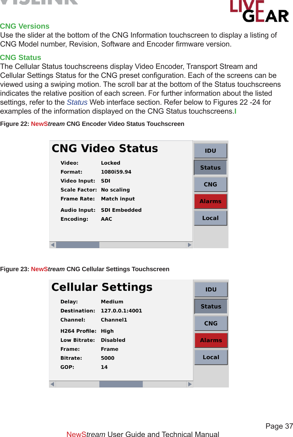
![Page 38NewStream User Guide and Technical ManualFigure 24: NewStream CNG Transport Stream Status Touchscreen NewStream Video Cellular Transmitter Data UsageThe monthly operating cost of a NewStream transmitter is entirely dependent upon the consumption of wireless broadband data. Wireless service providers typically offer monthly data packages with a maximum “use-it-or-lose-it” usage capped in gigabytes [GB] before data overuse charges are implemented, usually in 1 GB increments.A key attribute of H.264 AVC [MPEG-4 Part 10] encoding is that HD quality video can be transmitted at less than half the data rate required by MPEG-2. While broadcast video streaming quality is regarded more subjectively than classic contribution and distribution standards, there are some basic guidelines that you can adopt to determine the appropriate data rate required in a given situation.The degree of video motion to be encoded directly impacts the upload data rate, typically expressed in megabits per second [Mbps]. For example, low motion 29.97/30 fps [frames per second] video, often referred to as “talking head” video, requires a video encoding data rate ranging between 1.0 - 3.0 Mbps, whereas fast motion video, such as a sporting event, can require data rates as high as 8 Mbps, depending on the resolution [e.g. 720p/1080i] selected. An average data rate of 3.0 Mbps provides approximately 30 hours of video transmission consuming about 40 GB of data. Encoding at 6.0 Mbps consumes up to 80 GB of data, and at 8.0 Mbps, slightly more than 105 Mbps. NewStream transmits video using up to six wireless network services simultaneously. The system is designed to level load or equally distribute the total amount of data being transmitted [i.e. uploaded] provided that there is equal wireless network availability for each of the modems. In this ideal case, the total data used is equally distributed across each of the six modems. In reality, network connection accessibility varies from one venue to another and is also subject to its availability from a loading perspective.](https://usermanual.wiki/Microwave-Radio-Communications/NST2G7G/User-Guide-2564620-Page-38.png)
![Page 39 NewStream User Guide and Technical ManualFrom a cost savings standpoint, it is judicious to set the maximum video encoding data rate to the lowest level required to support the kind of video being produced. In addition, NewStream’s adaptive bit rate encoding technology automatically reduces the encoding data rate based upon the degree of motion detected, to further enhance data usage conservation. Satellite [SNG] OperationNewStream’s satellite system allows you to transmit using your existing equipment. Your Block Up-converter [BUC] is used in the transmission [uplink] of satellite signals. It converts a band of frequencies from a lower frequency to a higher frequency. There are three frequency tuning options in satellite mode: Frequency Tuning in L-Band [Block-upconverter disabled], Frequency Tuning with BUC enabled in Ka, Ku and C bands and with either High or Low side local oscillators. Additionally, you can set up preset frequencies in Remote control categorized by specifi c channels [Channel tuning].SNG functionality allows user-defi nable frequency and power level confi guration. SNG modes have fi ne control of frequencies down to 1 KHz gradations and power outputs down to 0.1 dB gradations. To facilitate this, the up/down/left/right and enter buttons to allow you to easily select frequency and power level in local control on the front panel.As mentioned for Microwave and Cellular control, set the IDU to Remote Mode and go to the Modify Presets Web interface to make unique copies of the SNG Presets in order to create customized presets that your operators will use during broadcast. For more information refer to the Modify Presets section. For Remote Control operation see the sections below: Confi guration Mode touchscreen and Remote Operation Using the Web Interface.In SNG mode, the three OLED buttons on the right [Figure 5 items K and L] are not used for antenna control. Instead, they have been re-purposed for the Left and Right movement as arrow buttons. Touchscreen Display for SNG OperationSNG Sub-menuWhen in Satellite Mode, the touchscreen replaces the ODU sub-menu with an SNG sub-menu. Under this sub-menu the following information is displayed:o Channel Plan Mode or Frequency Tune Mode selection• You can select either Channel Plan Mode or Frequency tune mode via this sub-menu.o Block Up-converter [BUC] LO Frequency - button in the BUC Setup touchscreen• Spectrum Non-Inverted or Spectrum Inverted Selection underneath BUCPower Level SelectionThe section that previously showed ENG power level is replaced with a section that shows SNG power output from the NewStream . This section also allows you to set a power level between -40.0dBm and +5.0dBm with resolution up to 0.1 dBm.](https://usermanual.wiki/Microwave-Radio-Communications/NST2G7G/User-Guide-2564620-Page-39.png)
![Page 40 NewStream User Guide and Technical ManualFrequency SelectionBlock Up-converter OptionsWhen using Block Up-converter Options, you are able to enter the frequency that you want and the spectrum inversion properties of the Block Up-converter. The NewStream tunes the L-Band modulator with the proper calculation. This allows you to enter the LO [Local Oscillator] frequency of the Block Up-converter that you are using, and set which type of LO injection is used by the BUC. Low side LO indicates a non-inverted spectrum and High side LO, an inverted spectrum. See Satellite Frequency Tune Mode - BUC Enabled - IDU Touchscreen Control, on the next page, for more infromation. Refer to Frequency Tuning Example With BUC Enabled for detailed instructions.You can also setup as many as 99 Channels that designate specifi c frequencies and use the Channel Plan option [a.k.a Channel Tuning in remote control] to select them. You must setup these channels via the Web interface. Refer to the Frequency Plans Page [SNG] for more information. Frequency 16x2 Character DisplayIn Satellite Channel Plan Mode, the two lines of the frequency display window [Figure 5 item E] will show CH # Frequency in MHz. The frequency shown will always be the Frequency output of [BUC LO + L-Band IF if Spectrum Non-Inverting Low Side] or [BUC LO – L-Band IF Spectrum Inverting High Side]. If BUC LO is not entered, use L-Band IF frequency. In Frequency Tune Mode, the two lines of the frequency display window [Figure 5 item E] will show Frequency Tune Mode Frequency in MHz. The frequency shown here is always the desired frequency output of the BUC. If the Block Up-converter Local Oscillator is not entered, the output will be between 950 -1750 MHz. Power Rocker SwitchThe RF power level is displayed on the touchscreen, in the lower right corner. You can press the RF Adjustment rocker switch up or down [Figure 5 item B] to increment or decrement the power in .5dBm steps. Exact levels can be entered by pressing the Power button on the 5” touchscreen display. The rocker will always move to the nearest 0.5dB, even if the last number was set to an in-between power level. Example: If you set the power to 0.2dBm on the touchscreen, then press the rocker up button, the power will show 0.5dBm. Likewise, if the power reads 0.2dBm and you press the rocker down button, this will read 0.0 dBm.The L-Band power ranges from -40.0d B to +5.0 dB in 0.1dB increments. The power level will always return to the last used power level. A typical application is to set the L-Band power to the correct level [-12dB is typical] to satisfy the satellite amplifi er’s input and the control power to the satellite using the amplifi ers control panel.](https://usermanual.wiki/Microwave-Radio-Communications/NST2G7G/User-Guide-2564620-Page-40.png)
![Page 41NewStream User Guide and Technical ManualFigure 25: NewStream SNG Information Touchscreen - Frequency Tune SNG Information - Frequency Tune Mode - IDU Touchscreen ControlTo change settings within the SNG Information touchscreen, in Local Mode, press the Mode: botton to toggle to Frequency Tune Mode [see Figure 25]. Next, press the Power: button to display the numeric keypad, type the value in dBm and then press the Enter key on the keypad to set the L-Band power level. L-Band power settings range from -40 to 5 dBm. When you press the CW [Carrier] button [Figure 5 item D], the power level selected is displayed in the lower right of the touchscreen below the red bar graph, in the lower right of the touchscreen. The CW toggle will disable the Mode and Frequency settings while the Carrier is On. When you press the Frequency: button, the numeric keypad displays allowing you to set the SNG frequency. You must set the Block Up-converter frequency to the correct level, which is dependent on your system’s Block Up-converter. Press the Enter key shown on the keypad after each of the keypad actions.If you want to use the IDU front panel buttons and rocker switches to set Satellite frequencies, select an SNG Preset and start with the rocker switch [Figure 5 item G], that controls each digit of frequency, as displayed within the Frequency 16x2 display. You can move the cursor within the Frequency 16x2 display to increment the digits of the numeric display using the left/right arrow buttons [Figure 5 items K and L]. Selecting the frequency setting feature automatically sets the cursor to the leftmost position and causes the Enter button [Figure 5 item I] to start blinking amber. Pressing [Figure 5 item L] right arrow allows movement of the cursor to the right by one digit and then using the rocker switch [Figure 5 item G] you can increment that digit up or down. You can set the cursor to the left by using the left arrow [Figure 5 item K]. When you are satisfi ed with the entry, press the Enter button [Figure 5 item I] to save the new frequency. If no action occurs after 15 seconds, the frequency window reverts to the last frequency set. Frequency settings persist from one power cycle to the next.](https://usermanual.wiki/Microwave-Radio-Communications/NST2G7G/User-Guide-2564620-Page-41.png)
![Page 42 NewStream User Guide and Technical Manual• If a Block Up-converter frequency is entered and the spectrum is non-inverting Local Oscillator [LO] type is Low Side, the frequency range is 950.000 MHz to 1750.000 MHz above the Block Up-converter frequency in 1kHz steps.• If a Block Up-converter frequency is entered and the spectrum is inverting LO type is High Side, the frequency range is 950.000 MHz to 1750.000 MHz below the BUC frequency in up to 1 kHz steps.When you select the Frequency Tune mode with the Block Up-converter disabled, your range exists in L-Band [950.00 - 1750.00 MHz] and can be modifi ed in 1 kHz steps as shown below in Figure 26. Figure 26: NewStream SNG Touchscreen - BUC Setup Frequency Tune Mode SNG BUC Setup - Frequency Tune Mode - IDU Touchscreen ControlWhen you swipe the slide control at the bottom of the SNG Information touchscreen, the BUC Setup touchscreen appears, as shown in the fi gure below. To Enable the Block Upconverter in Frequency Tune Mode, press the BUC: Enable/Disable button, as shown in Figure 26.When the NewStream IDU is in Frequency Tune Mode, under Local control, the Satellite BUC Setup touchscreen allows you to set a frequency in 1 kHz increments on the IDU touchscreen. This touchscreen also allows you to select BUC LO Type: to the Low or High side Local Oscillator. Pressing the BUC LO Freq.: button also displays the numeric keypad, allowing selection of the Block Up-converter Local Oscillator frequency. There is also the RF Adjustment rocker switch [Figure 5 item B] next to the bottom right corner of the touchscreen that is available for power adjustment on the IDU front panel.](https://usermanual.wiki/Microwave-Radio-Communications/NST2G7G/User-Guide-2564620-Page-42.png)
![Page 43NewStream User Guide and Technical ManualSNG Information - Channel Plan Mode - IDU Touchscreen ControlPress the Frequency Tune button to toggle to the Channel Plan touchscreen, as shown in Figure 27. When the NewStream is in Satellite Channel Plan Mode, you select a frequency by scrolling through a pre-confi gured listing of channels. The frequency selection does not link presets and channels. You can scroll through the list of channels that are pre-confi gured via the rocker switch [Figure 5 item G] and press the Enter button [Figure 5 item I] to select the desired frequency. The Enter button [Figure 5 item I] blinks amber as you scroll through the list, and reverts back to the last known selected frequency if there is no action for 15 seconds. Channel selection persists from one power cycle to the next.NOTE: You must fi rst create an SNG Channel Plan via the SNG Frequency Plans Page in Remote control to use the channel plan setting under Local control with the IDU touchscreen. Refer to the Channel Plan example in the Satellite Frequency Plans [SNG] Web interface section.Figure 27: NewStream SNG Information Touchscreen - Channel Plan ModeWhen you operate SNG in Channel Plan Mode, the Block Downconverter Setup touchscreen is disabled.](https://usermanual.wiki/Microwave-Radio-Communications/NST2G7G/User-Guide-2564620-Page-43.png)
![Page 44 AirStream User Guide and Technical ManualFrequency Tuning Example With BUC EnabledIf the BUC Spectrum Non-Inverting LO Type is Low side, the sum of the NewStream frequency output IF and BUC is equal to: LO + [L-Band IF from NewStream] = Frequency display If the BUC LO Type is High Side is Spectrum Inverting, the difference between the frequency output IF and BUC is equal to: LO – [L-Band IF from NewStream ] = Frequency displayAs the name implies, Spectrum Non-Low Side LO type Inverting does not invert the Satellite Modulation however, Spectrum Inverting High Side Local Oscillator Type does invert the spectrum. If a Spectrum Inverting Low Side Block Up-converter is selected, the NewStream automatically toggles the spectrum inversion from the selection in the preset. You are not shown this inversion, as the Spectral inversion in the preset refl ects your selection. This allows the same set of presets to be used regardless of whether a Low side or High Side Block Up-converter is used. Example: In KU Satellite operation, a fi xed-spectrum Low Side LO Type non-inverting [BUC] Block Up-converter frequency @ 13,050 MHz is used. The KU range is 14,000 - 14,800MHz.Front Panel StateEnter 13.050 MHz into BUC frequency fi eld and select Spectrum Non-Inverting Low Side LO Type.• Desired frequency = 14000 MHz // 13050 MHz + 950 MHz = 14000 MHz // the L-Band IF tunes to [950MHz] =950MHz• Desired frequency =14275 MHz // 13050 MHz + 1255 MHz = 14250 MHz // the L-Band IF tunes to 1255 MHzSNG StatusThe Satellite Status touchscreens consist of four information displays for the current SNG preset. Each of the pages can be viewed using a swiping motion. The scroll bar at the bottom of the Status touchscreens indicates the relative position of each screen. For further information about the listed settings, refer to the Status Web interface section. Refer above to Figures 14 through 17 for examples of the listed information for SNG mode.](https://usermanual.wiki/Microwave-Radio-Communications/NST2G7G/User-Guide-2564620-Page-44.png)
![Page 45 NewStream User Guide and Technical ManualSteps to Stream Video in SNG ModeAfter confi guring SNG Presets, you can continue in Remote mode to create Channel Plans to allow quick selection of frequencies used to begin transmitting video and audio signals. Refer to the Web interface Frequency Plans Page [SNG] section below for more information. The following steps must be followed to begin Satellite transmission while in Remote Mode. Each of the steps can also be done using the front panel in Local mode, the buttons and switches used are noted.1. Confi gure SNG Presets and then select the preset you will use for broadcast. In Local mode, you would select using the rocker switch [Figure 5 item H] and then pressing the Enter button [Figure 5 item J]. 2. Set frequency tuning mode method: a. Frequency Tune BUC disabled [L-Band] - refer to Figure 25. b. Frequency Tune BUC enabled [Ka or Ku-bands] - refer to Figure 27. c. Channel Plans setup to quickly tune to pre-confi gured and stored frequency choices - refer to Figure 26. 3. Set the Power level using the RF Level rocker switch to the desired level [Figure 5 item B]. 4. Press CW ON to enable the carrier and readjust the power level as needed. It is recommended that you start on a lower power level. This action starts unmodulated satellite transmission.5. Press MOD ON to begin modulated satellite transmission. 6. Either MOD OFF or CW OFF can be pressed to stop transmission.](https://usermanual.wiki/Microwave-Radio-Communications/NST2G7G/User-Guide-2564620-Page-45.png)
![Page 46NewStream User Guide and Technical ManualIDU Touchscreen Last State DisplayedWhen power is reapplied to the IDU, most of the confi guration options of the NewStream IDU return to the last operational state, although there are a few exceptions to this rule. In general, RF energy is not applied upon startup in order to protect downstream ODUs. Instead, any state variables that control RF energy default to the powered down state. All other options retain the last state. The following list describes the state variables explicitly.Common variables:o Frequency – Save last stateo Antenna Polarity – Save late stateo Antenna Switch – Save last stateo RF Band – Save last stateMicrowave:o RF Power [Hi/Low/Adj]– Save last stateo Power Amp – Always default to off on powerupSatellite:o RF Carrier – Always default to off on power upo RF Modulation – save last state Cellular:o Cell Transmit – Always default to off on powerupIDU Touchscreen States on Startup or Preset ChangeWhen power is applied to the NewStream IDU, the state of each touchscreen and the associated buttons display the operational state last confi gured, prior to shut down, with the following exceptions:o The PA On / Off OLED [ENG], or carrier on / off OLED [SNG] are always set in the off or standby state.o The Cellular On / Standby button is always set in the standby state. o The 5” touch screen always starts at the default main screen [as shown in the cover photograph].o When an ENG or SNG preset is selected and initiated [you must press the Apply button on front panel to initiate] the Power Amplifi er [PA] or Carrier [CW] OLED will return to the standby state.o When a frequency is selected and initiated, the PA or CW OLED will return to the standby state.](https://usermanual.wiki/Microwave-Radio-Communications/NST2G7G/User-Guide-2564620-Page-46.png)
![Page 47 NewStream User Guide and Technical ManualRemote Operation Using the Web InterfaceNewStream‘s Web interface provides an alternate means of control and confi guration for NewStream when the operator selects the Remote control option in NewStream‘s touchscreen. Figure 29 displays an example of the Web interface in Remote control for the ENG mode, where multiple operators may confi gure the NewStream using the Web interface. Figure 31 and 32 display examples of the NewStream‘s SNG and CNG Web interface while in Local and Remote control modes. To toggle between Remote and Local control, you must press the Local button on the side menu and then the Local button displayed in the Confi guration Mode touchscreen, as shown in Figure 20.The Login page [see Figure below] is displayed when you access the default IP address http://192.168.1.10/. The Status page appears once you login [see the fi gure below]. The default User name and Password is admin. Examples of NewStream‘s various Status pages are shown in Figures 29-32. You can also access any Status page by clicking the logo. The page displayed is dependent on the preset selected.Figure 28: NewStream Login Page](https://usermanual.wiki/Microwave-Radio-Communications/NST2G7G/User-Guide-2564620-Page-47.png)
![Page 48 NewStream User Guide and Technical ManualMicrowave Status PageThe Microwave [ENG] Status Web page displays the following parameters of the NewStream transmitter:• Current Preset • RF Control• Encoding Status• Modulation Status• Frequency Control• Antenna Control • Cellular Control [Upgrade Option]• Cell Card Information [Upgrade Option]When you click the Current Preset drop-down, a list of available presets displays, allowing you to select an alternate. Within the RF Control options section, you are able to apply power to the Power Amplifi er [PA], the Carrier [CW] and the Modulation control. The Encoding and Modulation Status section displays read-only information. You may apply power to Cellular Transmission. The Frequency Control section provides a means to select Channels and Frequency Bands. The Antenna Control section provides a means to select the ODU antenna and change the ODU antenna’s Polarity. The Cellular Card Information section displays the signal strength of each SIM installed within NewStream. Confi gure PresetTo display Modify Presets, Frequency Plans, NewStream Settings, Manual Mode and License Manager, you must leave the Status page by clicking the Setup button. Refer to the Modify Preset page, as shown in Figure 33. The factory default presets cannot be modifi ed however, you may save them under a different name and then make changes to it using the Modify Presets page. Up to 99 new presets may be created for NewStream. • Refer to Figures 38 & 39 in the Frequency Plans sections for more information. • Refer to Figure 41 in the NewStream Settings section for more information.• Refer to Figures 34 through 37 in the Modify Presets sections for more information concerning creation of custom presets.Current PresetThe Current Preset fi eld appears when you use the drop-down to select a previously confi gured preset. When you click the Apply Preset button, the confi guration is applied to NewStream and the values that you have selected or modifi ed take effect for the current video transmission.Refresh StatusThe Refresh Status icon provides a means to update the page. Any entries that you have revised such as RF, Frequency or Antenna Controls are reloaded using this option. The Status screen is updated automatically however, under remote control this button ensures that your settings are updated pro-actively.](https://usermanual.wiki/Microwave-Radio-Communications/NST2G7G/User-Guide-2564620-Page-48.png)
![Page 49NewStream User Guide and Technical ManualFigure 29: NewStream Status Page [ENG Remote Control Mode]](https://usermanual.wiki/Microwave-Radio-Communications/NST2G7G/User-Guide-2564620-Page-49.png)
![Page 50 NewStream User Guide and Technical ManualMicrowave Status Page [Continued]Radio Frequency Control Power Amplifi er [ENG]This button allows you to augment NewStream’s transmission capabilities by turning on the RF power amplifi er. This button is used to toggle the power amplifi er between PA Standby and PA ON. The default state is Off. Carrier [SNG Upgrade Option]This button provides a means to toggle the CW carrier On and Off; enabling the carrier frequency output or disabling the carrier frequency output. The default state is Off. Modulation [SNG Upgrade Option]This button allows you to turn Modulation on or off. Power Level [ENG]This fi eld displays the RF output power in dBm of the microwave ODU.Power Amplifi er ModeThis fi eld allows the selection of a Power Amplifi er Radio Frequency Level of: • High• Low• Manual - if manual is selected, the Power level adjust is active and is used to set the RF level in 1 dB steps.Power Level [SNG Upgrade Option]This fi eld displays the Satellite News Gathering L-Band RF level that is output from the rear panel L-Band connector.Power Level AdjustThis fi eld displays the Electronic News Gathering Attenuation to which the NewStream is calibrated. You can use the arrow buttons to select an Attenuation level from 0 to 31. The range changes depending on which type of ODU is connected, NewStream or legacy.Attenuation [SNG Upgrade Option]This fi eld is used to adjust the L-Band power output in 0.5dB steps. You can use the arrow buttons to select an Attenuation level from 0 to 40.](https://usermanual.wiki/Microwave-Radio-Communications/NST2G7G/User-Guide-2564620-Page-50.png)
![Page 51 NewStream User Guide and Technical ManualMicrowave Status Page [Continued]Encoding Status This set of fi elds present the settings to which the NewStream’s Encoder is currently set. These fi elds are read-only. Manual mode is accessed by the Setup drop-down menu. For further information refer to the Manual Mode Pages.Video StatusThis LED is lit green when video encoder is sending a signal to the designated receiver. It is lit red when Video transmission has stopped or when the video encoder is powered down.Video EncodingThe Video Encoding fi eld displays one of three options:• MPEG2• H.264• External ASIVideo InputThe Video Input fi eld displays one of the following options:• NTSC• NTSC No Pedestal• PAL• PAL-M • PAL-N• BARS-525• BARS-625 • 720p50• 720p59.94• 1080i50• 1080i59.94• SDI-525• SDI-625• HD BarsVideo BitrateThe Video Bitrate value ranges from 0-99.999 Mb/s.Profi leThe Profi le fi eld Profi le values differ depending on encoding type [H.264 or MPEG2]. The MPEG-2 SD example is:• 4:2:0 MP@ML• 4:2:2 P@ML](https://usermanual.wiki/Microwave-Radio-Communications/NST2G7G/User-Guide-2564620-Page-51.png)
![Page 52 NewStream User Guide and Technical ManualMicrowave Status Page [Continued]Modulation StatusThe Modulation Status fi elds present NewStream’s microwave settings for the selected preset. Modulation ModeThis fi eld displays one of the following modulation classes for each microwave preset:• COFDM-DVB-T — Coded Orthogonal Frequency - Division Multiplexing - Digital Video Broadcasting — Terrestrial• LMS-T — Link Modulation Scheme —Terrestrial • DVB - S — Digital Video Broadcasting — Satellite Mode• DVB - S2 — Digital Video Broadcasting —Satellite ModeModulationThis fi eld displays the following modulation classes for each microwave preset in the Microwave Settings page. Moving up the scale of modulations allows higher throughput but at the cost of robustness:• QPSK — Quadrature phase-shift keying• 16-QAM — Quadrature amplitude modulation • APSK — Amplitude Phase-shift Keying [for both 16 and 32-APSK]• 64 - QAM — Quadrature amplitude modulationFECForward Error Correction [FEC] or channel coding is a technique used for controlling errors in data transmission over unreliable or noisy communication channels. This fi eld displays the FEC for the existing microwave preset. Lower fractions are more robust to noise and fading but at the cost of reduced information bandwidth. Common FEC values include:• 1/4• 1/2• 1/3• 2/3• 3/4• 5/6• 7/8Guard IntervalThe Guard Interval is a method used to prevent interference within distinct transmissions. The Guard Interval confi gured for the microwave preset is displayed in this fi eld. The Guard Interval values include:• 1/32• 1/16• 1/8• 1/4](https://usermanual.wiki/Microwave-Radio-Communications/NST2G7G/User-Guide-2564620-Page-52.png)
![Page 53 NewStream User Guide and Technical ManualMicrowave Status Page [Continued]BandwidthThe Bandwidth value confi gured for the microwave preset is displayed as one of the following:• 6 MHz• 7 MHz• 8 MHz• 10 MHz• 20 MHzSpectrumThe Spectrum fi eld displays either Normal or Inverted.ASI BitrateThe Video Bitrate displayed ranges from 0 to 99.999 Mb/s.Antenna Polarization ControlThe Antenna Polarization Control section presents NewStream’s ODU antenna settings for the selected preset. The fi elds allow selection of ODU Polarity and the antenna to which the polarity is to be applied, as shown in Figure 29.PolarityThis drop-down fi eld allows you to select from the following:• Vertical• Horizontal• Left Circular[LC]• Right Circular [RC]AntennaThis fi eld allows for the selection of ODU 1 or 2. Note that the antenna switch function can be disabled if no antenna switch is being used.](https://usermanual.wiki/Microwave-Radio-Communications/NST2G7G/User-Guide-2564620-Page-53.png)
![Page 54NewStream User Guide and Technical ManualMicrowave Status Page [Continued]Alarm IndicatorsWhen an Alarm is activated on the IDU, it will be indicated on the top, right-hand corner of the Status page, as shown below in Figure 30. The Alarm may indicate a cautionary warning or a critical situation, as shown in the example. Click the Alarm icon to display a Warning/Alert dialog box or mouse over the icon to view alarm details, as shown in the example. Figure 30: NewStream Alarm Indicator on Status Page and Message Dialog Box](https://usermanual.wiki/Microwave-Radio-Communications/NST2G7G/User-Guide-2564620-Page-54.png)
![Page 55NewStream User Guide and Technical ManualFigure 31: NewStream Status Page [CNG Local Control Mode]Cellular Status PageA CNG Preset is displayed in the example below. If you are operating in Remote Control, you are allowed the choice of changing the preset within the Status page or initiating Cellular Transmission. Figure 31 shows the system in Local Control, where the Web page is read-only.](https://usermanual.wiki/Microwave-Radio-Communications/NST2G7G/User-Guide-2564620-Page-55.png)
![Page 56 NewStream User Guide and Technical ManualCellular Status Page [Continued]Cellular Card InformationThis status listing displays each cellular card’s RSSI. The RSSI is the relative received signal strength in arbitrary units. RSSI is an indication of the power level being received by the antenna. The lower the RSSI number, the stronger the signal. Refer to the CNG Touchscreens section for more information.When you click the manage icon shown within the Cell Card Info box, the Cell Modem Confi guration dialog box displays providing a means of confi guring each individual modem of the those available. Modem #The Modem number drop-down fi eld allows you to select one of six modems supported by NewStream.ModeThe Mode drop-down provides the means to select Auto or Custom Mode.APNThe Access Point Name is a confi gurable network identifi er used by NewStream when connecting to a GSM carrier. The carrier examines the APN identifi er to determine the network connection type for the NewStream transmitter. The APN determines which IP addresses are to be assigned to NewStream, which security methods to be used, and how or if, it will be connected to a private network.Login NameThe Login Name identifi es those administrators that are responsible for the maintenance of the NewStream cellular modems. Type your user name in this fi eld to submit your revised modem cofi guration.PasswordType the Password associated with your Login Name in this fi eld to authenticate the submission. PINThis fi eld provides further authentication with a Personal Identifi cation Number. Submit or CancelTo make any changes to a Cell Modem Confi guration, click the Submit button or Cancel to retain existing settings. Cellular ControlThe Cellular Control Status presents NewStream’s cellular settings for the selected preset. Cellular TransmissionThis button allows you to turn Cellular Transmission On or Off. when operating in Remote Controll mode . The default state is STBY. [or Off]](https://usermanual.wiki/Microwave-Radio-Communications/NST2G7G/User-Guide-2564620-Page-56.png)
![Page 57NewStream User Guide and Technical ManualCellular Status Page [Continued]Video StatusThe Video Status LED idicates the current video transmission state. When lit green, the video signal is being transmitted to the LiveGear Receiver. When lit red, the signal is not being transmitted and an alarm state may be present [refer to Figure 31]. Destination StreamThis fi eld displays the IP Address that designates the destination for the cellular video stream - the LGR’s IP address. Port #This fi eld displays the Port number, which ranges from 1 to 65,535. Channel #This fi eld displays the LGR Channel number, which ranges from 1 to 6.Cell Mode [Delay]The NewStream transmitter has three cellular modes of operation: Low, Medium and High delay, offering fl exibility for optimizing overall video performance as a function of cellular link connectivity performance.Low - this delay mode is used in applications where there is very good 3G/4G cellular connectivity. This setting minimizes the overall video buffer size and allows for approximately 1 to 2 seconds of delay over the cellular network. This setting is to be used in areas where there is intermittent or degrading cell connectivity; in these areas there is a larger overall packet jitter which leads to an overfl ow of the video buffering or the loss of video frames. Medium - this delay mode offers the optimum video quality and an overall delay of less than 5 seconds while minimizing the loss of video frames. This mode is to be used with acceptable 3G/4G cellular network coverage.High - this delay mode uses the largest video buffer size to minimize the loss of video frames over the cellular link. Use this mode whenever 4G coverage is not present and 3G services are unreliable. When cell coverage is unknown, High delay should be used initially. Video InputThis fi eld displays the selection of Composite or SDI Cellular Video Input for the listed preset.](https://usermanual.wiki/Microwave-Radio-Communications/NST2G7G/User-Guide-2564620-Page-57.png)
![Page 58NewStream User Guide and Technical ManualCellular Status Page [Continued]Video ResolutionThe Video Input Resolution fi eld displays the following values:• 720p50, 720p60, 720p59.94• 1080i50, 1080i59.94, 1080i60• NTSC [National Television System Committee]• PAL [Phase Alternating Line]Scaling FactorThe Scaling Factor describes the use of magnifi cation in devices to compensate for differences between size of viewing areas.Frame RateFrame rate, also known as frame frequency and frames per second [FPS], is the frequency or rate at which NewStream unique consecutive images called frames. Frame rate is often expressed in frames per second [FPS] and is also expressed in progressive scan monitors as hertz [Hz].Profi leThe Profi le fi eld presents the H.264 settings for video, which are also available for Microwave and Satellite transmission. The Profi le fi eld displays one of the following values:• Baseline• Main• High• High 422GOPIn MPEG encoding, a Group of Pictures [GOP] specifi es the order in which intra-frames are arranged. The GOP is a group of successive pictures within an MPEG-coded fi lm and/or video stream. Each MPEG-coded fi lm and/or video stream consists of successive groups of pictures. The valid range of successive groups of pictures is from 0 to 60.Low BitrateThis fi eld displays whether Low Bitrate control is Enabled or Disabled.Frame StructureVideo frame structure is the division of defi ned lengths of media, such as a sequence of images in a video, into different fi eld information parts. Video frame structure commonly defi nes independent key frames, predicted adjacent frames, and bi-directional frmaes created from the comparison of multiple frames. Key frames contain all of the information of an image and the predicted and bi-directional frames contain the difference elements from other frames which results in much lower data that is required to recreate the images.](https://usermanual.wiki/Microwave-Radio-Communications/NST2G7G/User-Guide-2564620-Page-58.png)
![Page 59NewStream User Guide and Technical ManualCellular Status Page [Continued]Max BitrateThis fi eld displays a range of:• 256 kilobits per second [kbps]• 500 kbps• 768 kbps• 1.0 Megabit per second [Mbps]• 1.5 Mbps• 2.0 Mbps• 2.5 Mbps• 3.0 Mbps• 3.5 Mbps• 4.0 Mbps• 5.0 Mbps• 6.0 Mbps• 7.0 Mbps• 8.0 Mbps• 9.0 Mbps• 10.0 MbpsAudio Encoding 1 & 2The Audio Input Encoding types that are displayed in this fi eld include:• Off• MPEG Layer II — MPEG Audio Layer II is a core audio algorithm.• AAC — Advanced Audio Coding Audio Input The Audio Input Encoding values that are displayed in this fi eld include:• Analog • SDI Embedded — Serial digital interface [SDI] is a family of video interfaces that have been standardized by SMPTE. For example, ITU-R BT.656 and SMPTE 259M defi ne digital video interfaces used for broadcast-grade video. This mode embeds the audio into the SDI stream.• AES-EBU — The digital audio standard frequently called AES/EBU [aka AES3], is used for carrying digital audio signals between various devices.Service NameThis fi eld displays the name of the cellular service provider.Network NameThe Network Name or SSID, differentiates one WLAN from another, so all Access Points and all devices attempting to connect to a specifi c WLAN must use the same SSID to enable effective roaming. As part of this association process, a wireless client must have the same SSID as that entered in the Access Point or it will not be permitted to join the BSS.](https://usermanual.wiki/Microwave-Radio-Communications/NST2G7G/User-Guide-2564620-Page-59.png)
![Page 60NewStream User Guide and Technical ManualSatellite Status PageThe Status Web page that displays when you select an SNG preset is shown in the fi gure below. When in Remote control, you are able to change presets using the Current Preset drop-down and the Appy Preset button. Figure 32: NewStream Status Page [SNG Remote Control Mode]](https://usermanual.wiki/Microwave-Radio-Communications/NST2G7G/User-Guide-2564620-Page-60.png)
![Page 61 NewStream User Guide and Technical ManualSatellite Status Page [Continued]Radio Frequency Control Carrier This button provides a means to toggle the CW carrier On and Off; enabling the carrier frequency output or disabling the carrier frequency output. The default state is Off. Modulation This button allows you to turn Modulation on or off. Power Level This fi eld displays the Satellite News Gathering L-Band RF level that is output from the rear panel L-Band connector.Power Level This fi eld displays the Satellite News Gathering L-Band RF level that is output from the rear panel L-Band connector.Power Level AdjustThis fi eld is used to adjust the L-Band power output in 0.5dB steps. You can use the arrow buttons to select an Attenuation level from 0 to 40.Encoding Status This set of fi elds present the settings to which the NewStream’s Encoder is currently set. These fi elds are read-only. Video StatusThis LED is lit green when video encoder is sending a signal to the designated receiver. It is lit red when Video transmission has stopped or when the video encoder is powered down.Video EncodingThe Video Encoding fi eld displays one of three options:• MPEG2• H.264• External ASI](https://usermanual.wiki/Microwave-Radio-Communications/NST2G7G/User-Guide-2564620-Page-61.png)
![Page 62NewStream User Guide and Technical ManualSatelitte Status Page [Continued]Video InputThe Video Input fi eld displays one of the following options:• NTSC• NTSC No Pedestal• PAL• PAL-M • PAL-N• BARS-525• BARS-625 • 720p50• 720p59.94• 1080i50• 1080i59.94• SDI-525• SDI-625• HD BarsVideo BitrateThe Video Bitrate value ranges from 0-99.999 Mb/s.Profi leThe Profi le fi eld Profi le values differ depending on encoding type [H.264 or MPEG2]. The MPEG-2 SD example is:• 4:2:0 MP@ML• 4:2:2 P@MLDelayThe Delay fi eld displays one of these three values:• Low• Standard• Ultra LowGOPThe values of successive groups of pictures ranges from 0 to 60.Aspect RatioSD formats allow an Aspect ratio of either 4:3 or 16:9. HD formats aloow 16:9 only. The Aspect Ratio fi eld displays one of these two values:• 4:3• 16:9Service NameThis fi eld displays the 16 character service information name for the current preset.](https://usermanual.wiki/Microwave-Radio-Communications/NST2G7G/User-Guide-2564620-Page-62.png)
![Page 63NewStream User Guide and Technical ManualSatelitte Status Page [Continued]Audio Input 1 & 2The Audio Input Encoding values that are displayed in this fi eld include:• Test Tone • Analog • SDI Embedded • AES-EBU Balanced• AES-EBU UnbalancedAudio Bitrate [kbps] 1 & 2The Audio Bitrate values for Audio 1 & 2 are displayed in this fi eld.Audio Encoding 1 & 2The Audio Input Encoding types that are displayed in this fi eld include:• Off• MPEG Layer I — MPEG Audio Layer I is a core audio algorithm• MPEG Layer II — MPEG Audio Layer II is a core audio algorithm.• Linear PCM — Pulse-code modulation Frequency ControlThe Frequency Control status provides a means to select the microwave, cellular and satellite Channel and Band and to view the frequency at which NewStream is calibrated. These settings can be modifi ed using the Frequency Plan page, as shown in Figures 31 & 32.Tune Mode• Channel Tuning - Channel Tuning provides a means to confi gure preset frequencies that you can employ when in SNG operation from the front panel in Local Control [or also in Remote Control]. These frequencies are set up within Satellite Channels while in Remote control.• Frequency Tuning - This method of frequency selection can gbe done while in Local or Remote control, as described in the touchscreen SNG Operation section above and also in the Frequency Plans Web Page section below. The frequency tuning can be set for Block-upconverter [BUC] Disabled [L-Band] or BUC Enabled, as described below.ChannelThe frequency Channel can be selected using this drop-down fi eld. Channel options depend on the frequency band in which you are operating. There are standard frequencies broadcasters use, or which can be created. The frequency channel displays the list of stored channels for the RF band in use. This fi eld displays the name of the frequency channel that NewStream is set. This fi eld can be modifi ed in the Frequency Settings page in Remote control. Refer to the Frequency Plans Page [SNG].](https://usermanual.wiki/Microwave-Radio-Communications/NST2G7G/User-Guide-2564620-Page-63.png)
![Page 64NewStream User Guide and Technical ManualSatelitte Status Page [Continued]FrequencyThis box displays the BUC Frequency for which NewStream is currently set. With BUC [Block Up-Converter Enabling]The block up-converter [BUC] is used in the transmission [uplink] of satellite signals. It converts a band of frequencies from a lower frequency to a higher frequency. Modern BUCs convert from the L-Band to Ku-band, C-band and Ka-band. • BUC LO Type: This fi eld displays the BUC Local Oscillator [LO] Type frequency for which NewStream is currently set. You can select Low or High Side for your SNG system’s Local Oscillator.• BUC Frequency: This fi eld displays the BUC Frequency for which NewStream is currently set. • Frequency: This fi eld displays the Frequency for which NewStream is currently set. L-Band FrequencyThe ODUs operate on L-Band with BUC disabled. This fi eld displays the seleced L-Band frequency. Frequency PlanThis fi elld displays Satellite when using a SNG Preset.ApplyYou can reset frequency confi gurations by clicking the Apply button.](https://usermanual.wiki/Microwave-Radio-Communications/NST2G7G/User-Guide-2564620-Page-64.png)
![Page 65NewStream User Guide and Technical ManualSatelitte Status Page [Continued]Modulation StatusThe Modulation Status fi elds present NewStream’s microwave settings for the selected preset. Modulation ModeThis fi eld displays one of the following modulation classes for each microwave preset:• COFDM-DVB-T — Coded Orthogonal Frequency - Division Multiplexing - Digital Video Broadcasting — Terrestrial• LMS-T — Link Modulation Scheme —Terrestrial • DVB - S — Digital Video Broadcasting — Satellite Mode• DVB - S2 — Digital Video Broadcasting —Satellite ModeModulationThis fi eld displays the following modulation classes for each microwave preset in the Microwave Settings page. Moving up the scale of modulations allows higher throughput but at the cost of robustness:• QPSK — Quadrature phase-shift keying• 16-QAM — Quadrature amplitude modulation • APSK — Amplitude Phase-shift Keying [for both 16 and 32-APSK]• 64 - QAM — Quadrature amplitude modulationFECForward Error Correction [FEC] or channel coding is a technique used for controlling errors in data transmission over unreliable or noisy communication channels. This fi eld displays the FEC for the existing microwave preset. Lower fractions are more robust to noise and fading but at the cost of reduced information bandwidth. Common FEC values include:• 1/4• 1/2• 1/3• 2/3• 3/4• 5/6• 7/8SpectrumThe Spectrum fi eld displays either Normal or Inverted.](https://usermanual.wiki/Microwave-Radio-Communications/NST2G7G/User-Guide-2564620-Page-65.png)
![Page 66NewStream User Guide and Technical ManualSatellite Status Page [Continued]Symbol RateSymbol Rate [aka baud or modulation rate] is the number of symbol changes [i.e. waveform changes or signalling events] made to the transmission medium per second using a digitally modulated signal or a line code. The Symbol Rate is expressed in Mega symbols/second [Ms/s]. The valid range is 1.0000-36.0000 Ms/s.Roll OffRoll-off describes the steepness of a transmission function with frequency, in connection with fi lter circuits in the transition between a passband and a stop band.Values of Roll-off are expressed in percentages, ranging from:• 35%• 25%ASI BitrateThe Video Bitrate displayed ranges from 0 to 99.999 Mb/s.Modify Presets PageWhile viewing a Status page, click the Setup button to display the drop-down menu. The menu displays the following options:• Modify Presets• Frequency Plans• NewStream Settings• Manual Mode• License ManagerSelect Modify Presets to begin creating custom confi gurations for SNG, ENG and CNG transmission in the page shown in Figure 33. NewStream is confi gured with three factory default presets with the ability to create up to 99 custom presets. You can modify each preset name and its type in the Modify Presets page, as shown in the fi gure. You can confi gure additional settings for each custom preset by clicking the confi gure preset icon. Presets marked with the padlock symbol are factory defaults and cannot be modifi ed but can be used as a template for your custom presets. The active preset is highlightedhighlighted. In the Modify Presets page you can use the Export tool to save custom presets to a fi le or to other IDUs. Additionally, you can import presets from a directory on your PC, to another IDU or to a USB fl ash drive using the tool which loads custom presets from a fi le. This feature can not be implemented while the system is transmitting.](https://usermanual.wiki/Microwave-Radio-Communications/NST2G7G/User-Guide-2564620-Page-66.png)
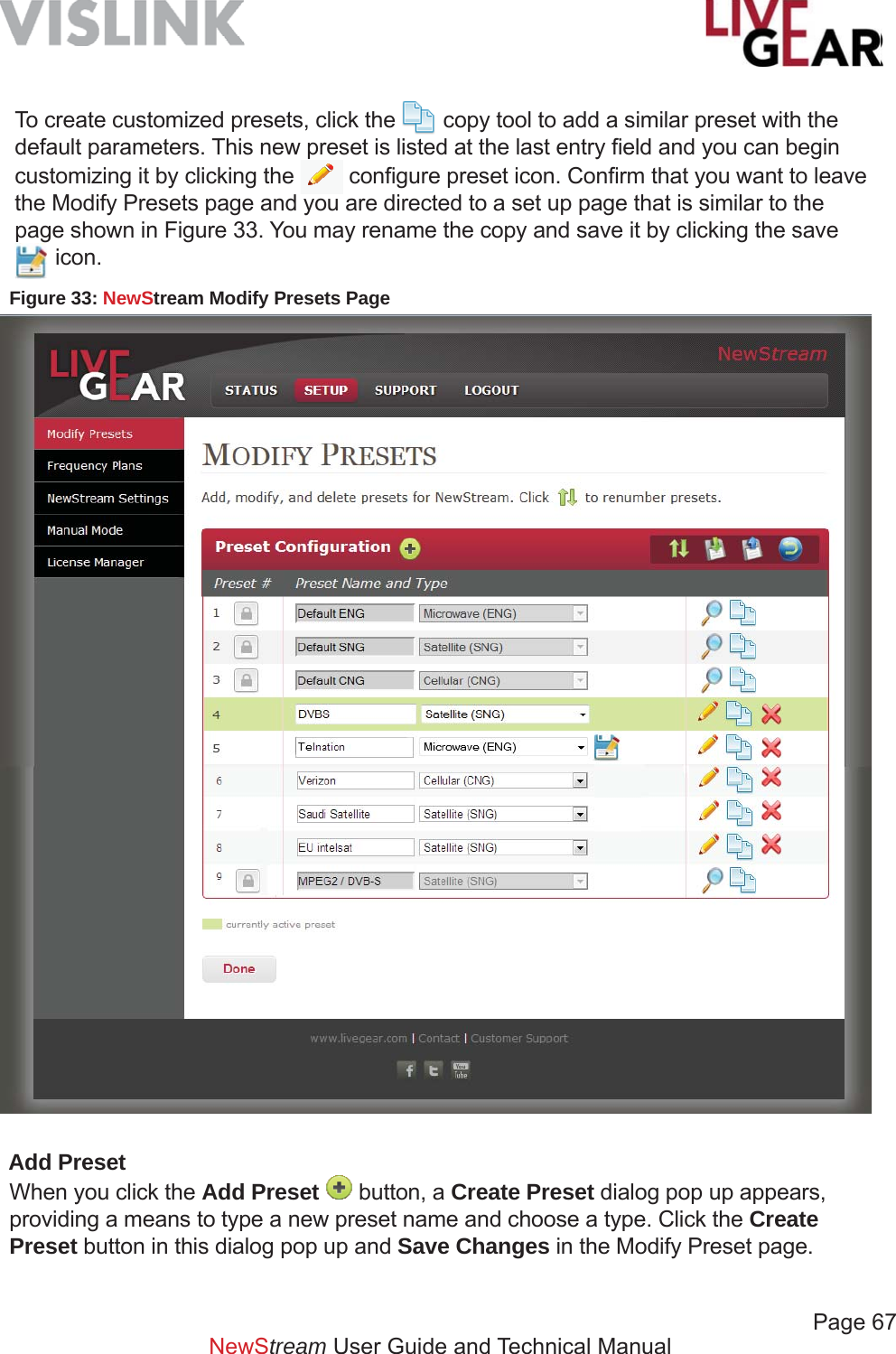
![Page 68 NewStream User Guide and Technical ManualPreset Confi gurationPreset Number [#]The Preset Number can be reordered. Click and drag the blue circle found in the column to the left of the Preset number [#] column to reorder the preset list. Click Save Changes to retain your modifi cation of the Preset Numbers.Preset NameSpecify an alphanumeric name of up to 32 characters for each preset. You may also use spaces and the following special characters: _ - ( ) / for the Preset Names. Note that preset names longer than 16 characters will scroll on the front panel 16 x 2 Preset display to show the complete name and then only show the fi rst 16 characters.Preset TypeThis drop-down fi eld provides a choice of Cellular, Satellite, Microwave or combinations of such for NewStream transmissions. The choices include:• Microwave [ENG]• Cellular [CNG]• Satellite [SNG]• Microwave & Cellular [ENG/CNG (Upgrade Option)]• Satellite & Cellular [SNG/CNG (Upgrade Option)]Export Presets to a FileUse the tool to save custom presets to a fi le. You can export presets in a directory on your PC, a shared server for other operators to access or on a USB fl ash drive. Import Presets from a FileUse the tool to load custom presets from a fi le. This feature can not be implemented while the system is transmitting. You can import a preset from a directory on your PC, a shared server or on a USB fl ash drive. See the Preset Export and Import section to learn how to Import and Export Presets in Local control.Restore Preset Confi gurationUse the tool to restore preset confi guration to the factory defaults and to remove all custom presets.View Preset SettingsUse the tool to view default preset settings. Save a PresetClick the Save icon to create a copy of a preset or to save modifi cations to an existing preset.Copy a Preset Use the tool to copy a selected preset. This is the action that allows you to create a customized preset. Once you have copied a default or another customized preset, save](https://usermanual.wiki/Microwave-Radio-Communications/NST2G7G/User-Guide-2564620-Page-68.png)
![Page 69NewStream User Guide and Technical Manualit with a unique name and confi gure its parameters as needed for your ENG, CNG or SNG broadcasts.Delete a Preset Use the tool to delete a selected preset.DoneClick the Done button once you’ve fi nished viewing the settings in the Modify Presets page. When you click Done no changes will be saved as you leave the page.Save ChangesTo retain any changes to the listed custom presets as well as renumbering changes to the listed custom presets, be sure to click the Save button once you’ve fi nished reordering listed presets in the Modify Presets page. This button appears in the Reorder Presets page.Factory Default PresetsThe NewStream IDU is shipped with three default presets:• Default ENG Microwave preset• Default SNG Satellite preset• Default CNG Cellular H.264 presetThe default presets are read-only but you can copy each default preset and rename it for future use and modifi cation. Examples of the settings for the Microwave preset are listed below:Default ENG Preset Encoder SettingsVideo SettingsVideo Encoding: MPEG2Video In: SDI-525SDI Horizontal Resolution: 720Aspect Ratio: 4:3Closed Captioning: OffVBI: OffEncoder SettingsProfi le: 4:2:0 MP@MLGOP: 12 Frames [1-60]Delay: StandardAuto Bitrate: OnVideo Bitrate: 5.529 Mb/s [0-99.999]Remux: OffSpectrum: InvertAudio SettingsAudio 1 Encoder: MPEG Layer IIAudio 1 Input: SDI EmbeddedAudio 1 Mode: Dual MonoAudio 1 Bitrate: 192 [kbs]Audio 2 Encoder: MPEG Layer IIAudio 2 Input: SDI EmbeddedAudio 2 Mode: Dual MonoAudio 2 Bitrate: 192 [kbs]Wayside DataFormat: OffBaud Rate: 19200](https://usermanual.wiki/Microwave-Radio-Communications/NST2G7G/User-Guide-2564620-Page-69.png)
![Page 70NewStream User Guide and Technical ManualDefault ENG Preset [Continued]Encryption SettingsEncryption Mode: OffSecurity Key: [Undefi ned & Hidden]Transport StreamService Name: preset1Network Name: pre1_nwProgram ID: [210]Network ID: [211]Transport ID: [212]Video PID: [213]PCR PID: [214]Audio A PID: [215]Audio B PID: [216]Data PID: [217]Modulation Settings Modulation Mode: DVB-TSpectrum: NormalModulation: QPSKFEC: 1/2Guard Interval: 1/8Bandwidth: 8 MHzCellular Settings CellularCell Mode Delay: LowDestination Stream: 8.8.8.8Port #: 4001VideoVideo Input: CompositeResolution: NTSCScale Factor: No ScalingFrame Rate: Match InputEncoderProfi le [H264]: BaselineGOP: 35 Frames [1-60]Low Bitrate: EnabledFrame Structure: MBAFFEncoder Bitrate: 50 [0 to 99.999] Transport StreamService Name: cell_vislinkNetwork Name: cell_vislink_nwProgram ID: [310]Network ID: [311]Transport ID: [312]Video PID: [313]PCR PID: [314]Audio A PID: [315]Audio B PID: [316]Data PID: [317]AudioAudio Encoding: MPEG Layer II Audio Input: SDI Embedded](https://usermanual.wiki/Microwave-Radio-Communications/NST2G7G/User-Guide-2564620-Page-70.png)
![Page 71NewStream User Guide and Technical ManualModify Presets Encoder SettingsOnce expanded, the Encoder Settings appear, as shown in Figure 35. This set of fi elds allows the confi guration of ENG, SNG or CNG options. The encoder settings fi elds include Video, Audio, Encoder and Encryption settings, as well as Transport Stream and Wayside Data confi guration fi elds.Figure 34: NewStream Modify Presets Setup Page - CollapsedModify Presets Setup PageWhen you select the Modify Presets menu item and confi rm this action, the following setup page displays, allowing you to modify the NewStream transmitter’s preset. The example shown is a SNG Preset that has been copied from the default SNG Preset [see the fi gure below]. When you click the button, the Encoder, Modulation or Cellular Settings Modify Presets Web options appear. Note that Modifying Presets is used to revise parameters and have the changes applied immediately, this automatically allows you to adjust NewStream‘s operating confi guration when transmission parameters change. The Modify Presets feature is designed to provide operational fl exibility as needed.](https://usermanual.wiki/Microwave-Radio-Communications/NST2G7G/User-Guide-2564620-Page-71.png)
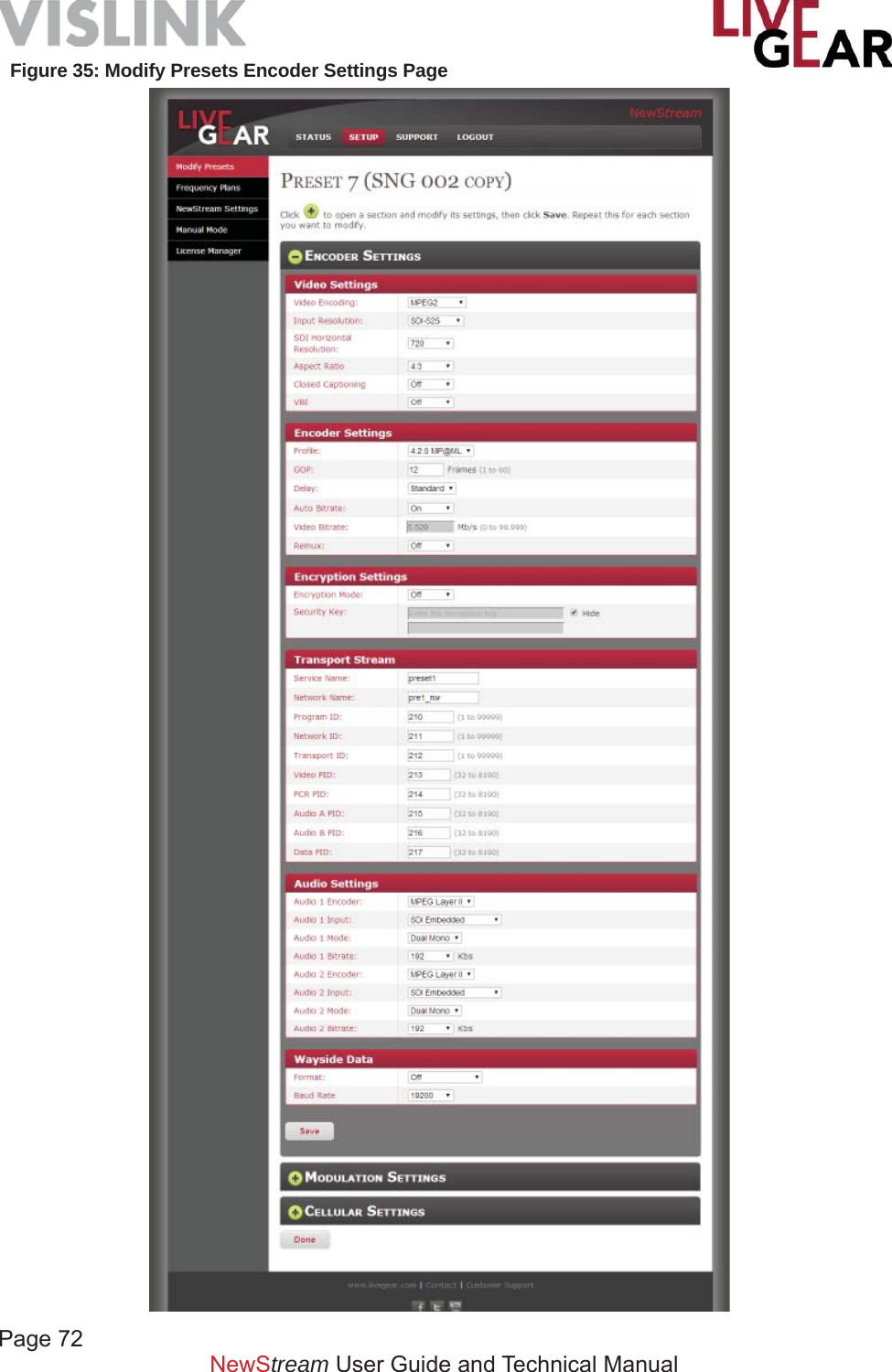
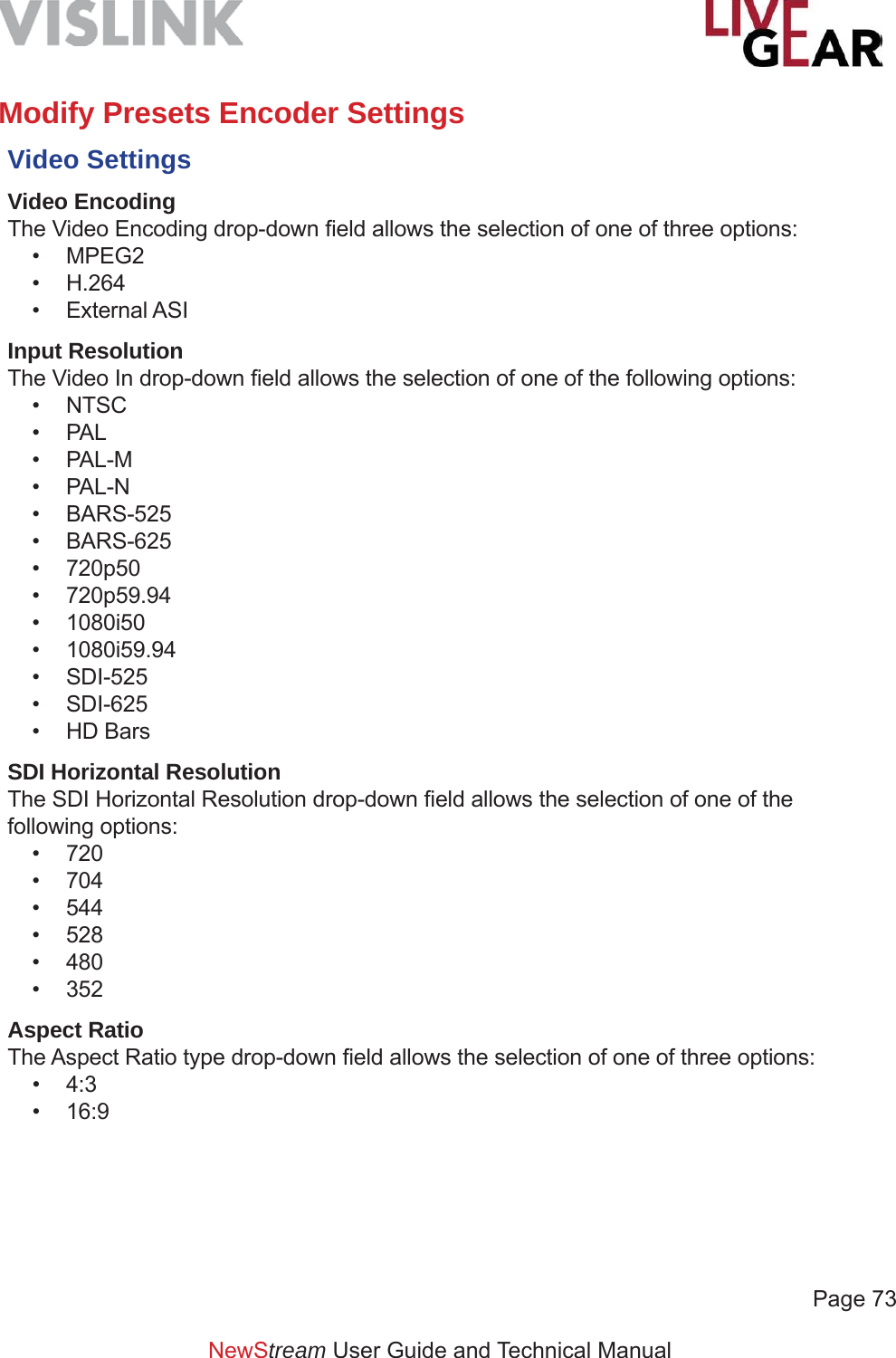
![Page 74NewStream User Guide and Technical ManualModify Presets Encoder Settings [Continued]Closed CaptioningThe Closed Captioning drop-down fi eld allows the selection of one of three options:• Off• CC-608• CC-708VBIThe Vertical Blanking Interval option can be enabled with the selection of On.Encoder SettingsProfi leThe Profi le type drop-down fi eld allows the selection of one of two options:• 4:2:0 MP@ML• 4:2:2 P@MLGOPIn MPEG encoding, a Group of Pictures [GOP] specifi es the order in which intra-frames are arranged. The GOP is a group of successive pictures within an MPEG-coded fi lm and/or video stream. Each MPEG-coded fi lm and/or video stream consists of successive groups of pictures. The valid range of successive groups of pictures is from 0 to 60. For “Intra Refresh,” enter 0 in this fi eld.DelayThe Delay type drop-down fi eld allows the selection of one of three options: • Low • Standard• UltraAuto BitrateThe Automatic Bitrate option can be enabled with the selection of On. Video BitrateThe Video Bitrate value ranges from 0-99.999 Mb/sRemuxThe Remux option can be enabled with the selection of On.](https://usermanual.wiki/Microwave-Radio-Communications/NST2G7G/User-Guide-2564620-Page-74.png)
![Page 75 NewStream User Guide and Technical ManualModify Presets Encoder Settings [Continued]Encryption SettingsThe Encryption Settings provide the selection of Encryption Mode and the Security Key. Encryption ModeThis fi eld allows selection of the following Encryption Modes for the microwave preset:• BISS1 — Basic Inter-operable Scrambling System, usually known as BISS, is a satellite signal scrambling system.• BISSE — Basic Inter-operable Scrambling System - Encrypted • OffSecurity KeyType a key in this fi eld to apply encryption to NewStream transmissions.Hide CharactersWhen the check box is selected, characters will not appear in the Security Key entry fi eld.Transport StreamThe following entry fi elds are used by the system to differentiate NewStream Transport Streams.Service NameThis fi eld provides a means to differentiate the NewStream Transport Stream with a unique Service Name. Network NameThis fi eld provides a means to differentiate the NewStream Transport Stream with a Network Name. Program IDThis fi eld provides a means to differentiate the NewStream Transport Stream with a Program Identifi cation [valid IDs range from 1 to 99999].](https://usermanual.wiki/Microwave-Radio-Communications/NST2G7G/User-Guide-2564620-Page-75.png)
![Page 76NewStream User Guide and Technical ManualModify Presets Encoder Settings [Continued]Network IDThis fi eld provides a means to differentiate the NewStream Transport Stream with a unique Network Identifi cation [valid IDs range from 1 to 99999]. Transport IDThis fi eld provides a means to differentiate the NewStream Transport Stream with a unique identifi cation [valid IDs range from1 to 99999].Video PIDThis fi eld displays the Video Packet Identifi cation for the NewStream Transport Stream [valid IDs range from 32 to 8190].PCR PIDThis fi eld displays the Program Clock Reference Packet Identifi cation for the NewStream Transport Stream [valid IDs range from 32 to 8190].Audio A & B PIDThis fi eld displays the Audio A and B Packet Identifi cation for the NewStream Transport Stream [valid IDs range from 32 to 8190].Data PIDThis fi eld displays the Data Packet Identifi cation for the NewStream Transport Stream [valid IDs range from 32 to 8190].Audio SettingsAudio 1 & 2 EncoderThe Audio Encoding parameters that are available in this fi eld include:• MPEG Layer I - MPEG Audio Layer I is a core audio algorithm.• MPEG Layer II - MPEG Audio Layer II is a core audio algorithm.• Linear PCM - Pulse-code modulation • OffAudio 1 & 2 InputThe Audio Input parameters that are available in this fi eld include:• Test Tone• Analog• SDI Embedded • AES-EBU Balanced• AES-EBU Unbalanced](https://usermanual.wiki/Microwave-Radio-Communications/NST2G7G/User-Guide-2564620-Page-76.png)
![Page 77 NewStream User Guide and Technical ManualModify Presets Encoder Settings [Continued]Audio 1 & 2 ModeThe Audio Mode parameters that are available in this fi eld include:• Stereo• Dual MonoAudio 1 & 2 BitrateThis drop-down fi eld presents a range of:• 128 kilobits per second [kbps]• 160 • 192 • 224 • 256 • 320 • 384 Wayside DataFormatThe Wayside Data Format parameters that are available in this fi eld include:• Off• TTV• CJM2 (Normal)• Low Delay CJM2Baud RateThe Baud Rate parameters that are available in this fi eld include:• 1200• 2400• 4800• 9600• 19200• 38400• 57600• 115200ApplyClick the Apply button to confi gure the encoder settings and submit preset changes to the IDU.](https://usermanual.wiki/Microwave-Radio-Communications/NST2G7G/User-Guide-2564620-Page-77.png)
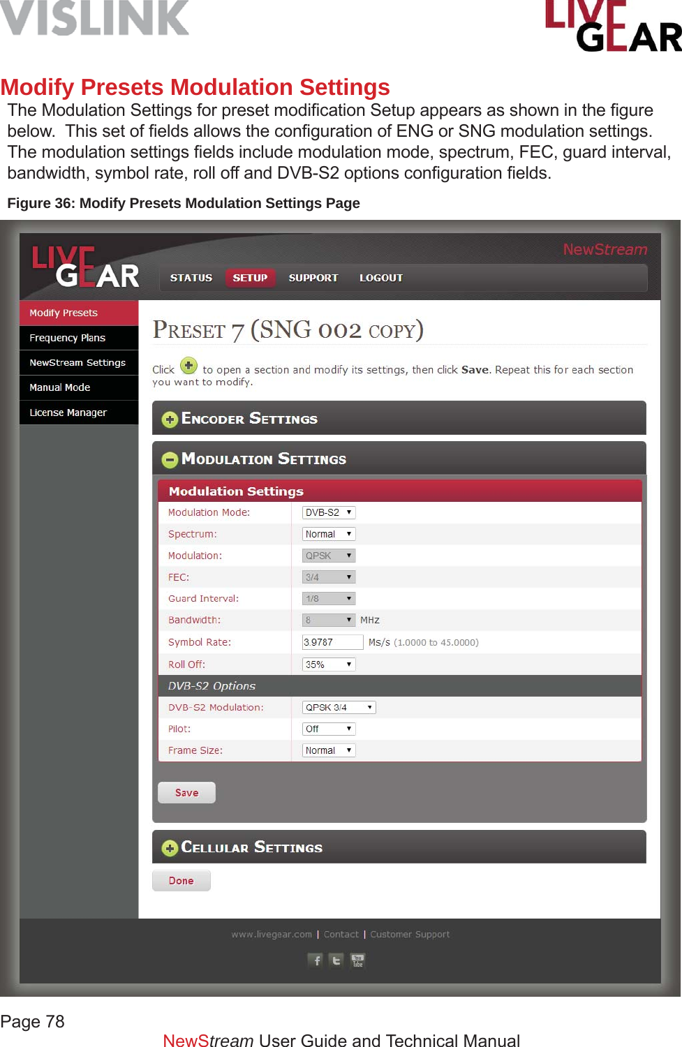
![Page 79NewStream User Guide and Technical ManualModify Presets Modulation Settings [Continued]Modulation SettingsModulation ModeThe Modulation Modes that are available are:• DVB-T• LMS-T• DVB-S [SNG only]• DVB-S2 [SNG only]SpectrumThe choices for Spectrum are Normal or Inverted.ModulationThis fi eld displays the following modulation classes that can be selected for each microwave, cellular or satellite preset found in the Modify Presets page. This list is combines the values for both DVB-T and DVB-S modulations. These modulation options will change for ENG, CNG and SNG presets. • QPSK — Quadrature Phase-Shift Keying• 16-QAM — Quadrature amplitude modulation• APSK — Amplitude Phase-shift Keying for both 16 & 32 APSK• 64-QAM — Quadrature Amplitude ModulationFECForward Error Correction [FEC] or channel coding is a technique used for controlling errors in data transmission over unreliable or noisy communication channels. This fi eld allows selection of the FEC for the existing microwave preset. The FEC values include:• 1/2• 2/3• 3/4• 5/6• 7/8Guard IntervalThe Guard Interval is a method used to prevent interference within distinct transmissions The Guard Interval confi gured for the microwave preset is displayed in this fi eld. The Guard Interval values include:• 1/32• 1/16• 1/8• 1/4](https://usermanual.wiki/Microwave-Radio-Communications/NST2G7G/User-Guide-2564620-Page-79.png)
![Page 80NewStream User Guide and Technical ManualModify Presets Modulation Settings [Continued]BandwidthThe 6, 7 and 8 MHz bandwidths are used for DVB-T and that 10 and 20 MHz are used for LMS-T.• 6 MHz• 7 MHz• 8 MHz• 10 MHz• 20 MHzSymbol RateSymbol Rate [aka baud or modulation rate] is the number of symbol changes [i.e. waveform changes or signalling events] made to the transmission medium per second using a digitally modulated signal or a line code. The Symbol Rate is expressed in Mega symbols/second [Ms/s]. The valid range is 1.0000-36.0000 Ms/s.Roll OffRoll-off describes the steepness of a transmission function with frequency, in connection with fi lter circuits in the transition between a passband and a stop band.Values of Roll-off are expressed in percentages, ranging from:• 35%• 25%DVB-S2 OptionsDVB-S2 ModulationThe DVB-S2 Modulation drop-down menu includes the following options:• QPSK 1/4, QPSK 1/3, QPSK 2/5, QPSK 1/2, QPSK 3/5, QPSK 2/3,• QPSK 3/4, QPSK 4/5, QPSK 5/6, QPSK 8/9, QPSK 9/10. • 8PSK 3/5, 8PSK 2/3, 8PSK 3/4, 8PSK 5/6, 8PSK 8/9, 8PSK 9/10. • 16PSK 2/3, 16PSK 3/4, 16PSK 4/5, 16PSK 5/6, 16PSK 8/9, 16PSK 9/10. • 32APSK 3/4, 32APSK 4/5, 32APSK 5/6, 32APSK 8/9, 32APSK 9/10.PilotTo assist carrier recovery, DVB-S2 can insert special “pilot symbols” at the physical layer. The Pilot option can be enabled with the selection of On, depending on satellite requirements., Frame SizeThe following Frame Size options are available, depending on satellite requirements:• Normal• ShortApplyThe Apply button activates the Modulation Settings that you have confi gured for the NewStream IDU.](https://usermanual.wiki/Microwave-Radio-Communications/NST2G7G/User-Guide-2564620-Page-80.png)
![Page 81NewStream User Guide and Technical ManualModify Presets Cellular SettingsThe Cellular Settings appear as shown in Figure 37. This set of fi elds allows the confi guration of CNG settings. The Cellular Settings fi elds include Cellular, Video, Encoder, Transport Stream and Audio parameters.Cellular Cell Mode DelayThe NewStream transmitter has three cellular modes of operation: Low, Normal and High delay, offering fl exibility for optimizing overall video performance as a function of cellular link connectivity performance.Low – this delay mode is used in applications where there is very good 3G/4G cellular connectivity. This setting minimizes the overall video buffer size and allows for approximately 1 to 2 seconds of delay over the cellular network. This setting is used in areas where there is good cellular connectivity. Medium – this delay mode offers the optimum video quality and an overall delay of less than 3 seconds while minimizing the loss of video frames. This mode is used with acceptable 3G/4G cellular network coverage. High - this delay mode uses the largest video buffer size to minimize the loss of video frames over the cellular link. Use this delay whenever 4G coverage is not present and 3G services are unreliable. It is recommended that you use Robust delay initially when cellular network coverage is unknown. Robust delay may be up to 6 seconds.Destination StreamType an IP Address to designate the destination for the cellular video stream. If you are using the LiveGear Receiver [LGR], use its IP address to communication with NewStream. Port #The Port number ranges from 1 to 65,535. Type a Port to designate the destination for the cellular video stream. If you are using the LiveGear Receiver [LGR], use the LGR Port number assigned for communication with NewStream. The default LGR ports are 4001 and 4002.ChannelThis fi eld displays the receiver channel. Type a Channel designated for the destination of the cellular video stream. If you are using the LiveGear Receiver [LGR], use a channel number assigned for communication with NewStream.](https://usermanual.wiki/Microwave-Radio-Communications/NST2G7G/User-Guide-2564620-Page-81.png)
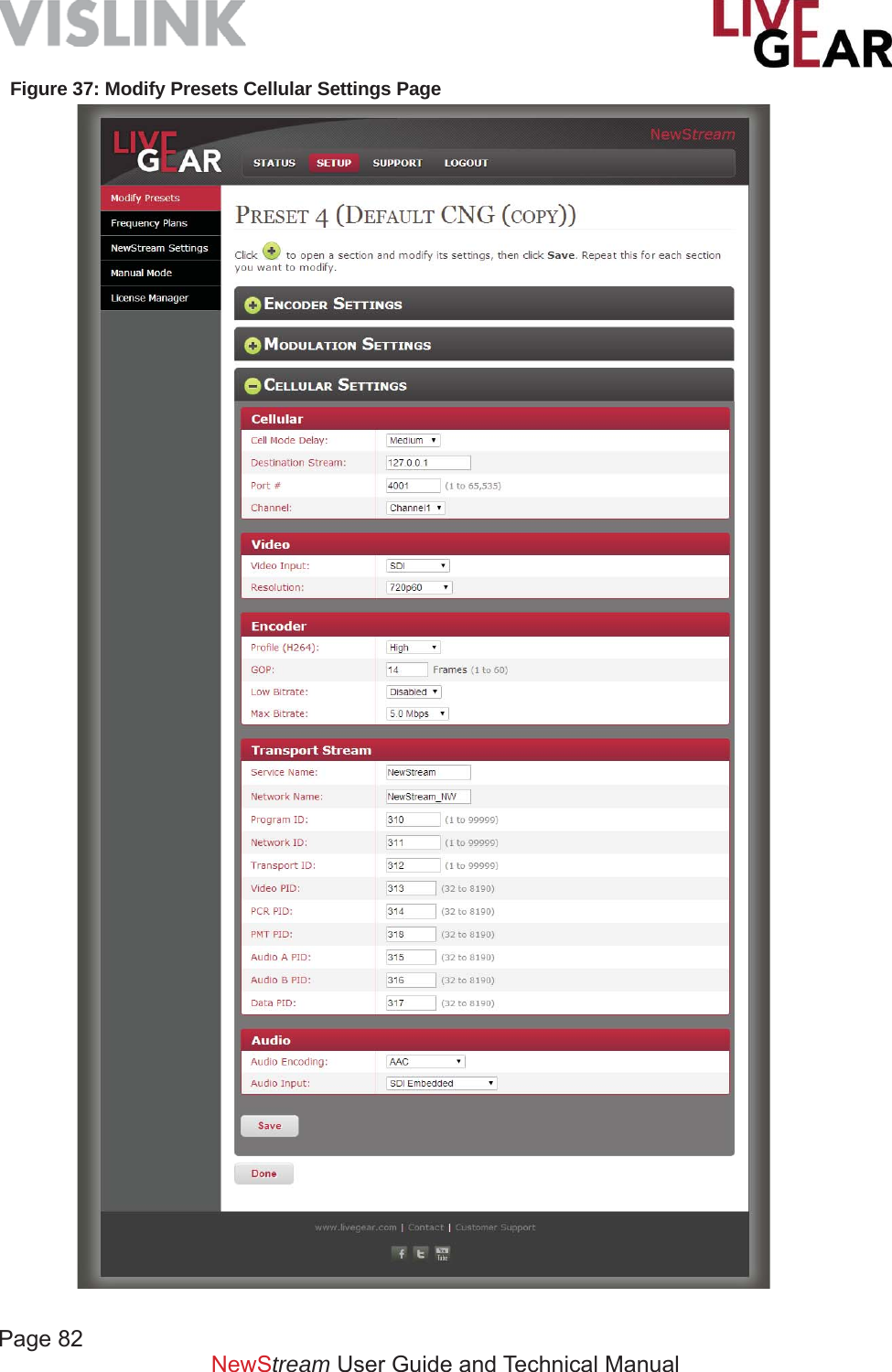
![Page 83NewStream User Guide and Technical ManualModify Presets Cellular Settings [Continued]Video The video settings for the NewStream transmitter CNG presets include the following parameters.Video InputThe Video Input drop-down fi eld allows the selection of one of two options:• SDI • Composite ResolutionThe Video Input Resolution drop-down selection fi eld provides the following choices:• 720p50• 720p59.94• 720p60• 1080i50• 1080i59.94• 1080i60• NTSC [National Television System Committee]• PAL [Phase Alternating Line]EncoderProfi le [H.264]The H.264 4:2:0 Profi le drop-down fi eld allows the selection of one of the following options:• Baseline• Main• HighGOPIn MPEG encoding, a Group of Pictures [GOP] specifi es the order in which intra-frames are arranged. The GOP is a group of successive pictures within an MPEG-coded fi lm and/or video stream. Each MPEG-coded fi lm and/or video stream consists of successive groups of pictures. The valid range of successive groups of pictures is from 0 to 60. For “Intra Refresh,” enter 0 in this fi eld.Low BitrateThis fi eld applies Low Bitrate control.• Enabled • Disabled](https://usermanual.wiki/Microwave-Radio-Communications/NST2G7G/User-Guide-2564620-Page-83.png)
![Page 84NewStream User Guide and Technical ManualModify Presets Cellular Settings [Continued]Max BitrateThis drop-down fi eld presents a range of:• 256 kilobits per second [kbps]• 500 kbps• 768 kbps• 1.0 Megabit per second [Mbps]• 1.5 Mbps• 2.0 Mbps• 2.5 Mbps• 3.0 Mbps• 3.5 Mbps• 4.0 Mbps• 5.0 Mbps• 6.0 Mbps• 7.0 Mbps• 8.0 Mbps• 9.0 Mbps• 10.0 MbpsTransport StreamThe following entry fi elds are used by the system to differentiate NewStream Cellular Transport Streams.Service NameThis fi eld provides a means to differentiate the NewStream Transport Stream with a unique Service Name. Network NameThis fi eld provides a means to differentiate the NewStream Transport Stream with a Network Name. Program IDThis fi eld provides a means to differentiate the NewStream Transport Stream with a Program Identifi cation [valid range: from 1 to 99999]. Network IDThis fi eld provides a means to differentiate the NewStream Transport Stream with a unique Network Identifi cation [valid range: from 1 to 99999]. Transport IDThis fi eld provides a means to differentiate the NewStream Transport Stream with a unique identifi cation [valid range: from 1 to 99999].Video PIDThis fi eld displays the Video Packet Identifi cation for the NewStream Transport Stream [valid range: from 32 to 8190].](https://usermanual.wiki/Microwave-Radio-Communications/NST2G7G/User-Guide-2564620-Page-84.png)
![Page 85NewStream User Guide and Technical ManualModify Presets Cellular Settings [Continued]PCR PIDThis fi eld displays the Program Clock Reference [PRC] Packet Identifi cation for the NewStream Transport Stream [valid range: from 32 to 8190].PMT PIDThis fi eld displays the Program Map Table [PMT] Packet Identifi cation for the NewStream Transport Stream [valid range: from 32 to 8190].Audio A & B PIDThis fi eld displays the Audio A and B Packet Identifi cation for the NewStream Transport Stream [valid range: from 32 to 8190].Data PIDThis fi eld displays the Data Packet Identifi cation for the NewStream Transport Stream [valid range: from 32 to 8190].AudioAudio EncodingThe Audio Input Encoding parameters that are displayed in this fi eld include:• MPEG Layer II — MPEG Audio Layer II is a core audio algorithm.• AAC — Advanced Audio Coding is the simplest and most widely used and supported Audio Input Encoding.• OffAudio Input This drop-down selection provides three options:• Analog• SDI Embedded — Serial digital interface [SDI] is a family of video interfaces that have been standardized by SMPTE. For example, ITU-R BT.656 and SMPTE 259M defi ne digital video interfaces used for broadcast-grade video. This mode embeds the audio into the SDI stream. • AES-EBU — The digital audio standard frequently called AES/EBU [aka AES3], is used for carrying digital audio signals between various devices.ApplyClick the Apply button to confi gure the cellular settings and submit preset changes to the IDU.DoneClick the Done button once you’ve fi nished viewing the settings in the Modify Presets page. When you click Done nothing will be saved as you leave the page.](https://usermanual.wiki/Microwave-Radio-Communications/NST2G7G/User-Guide-2564620-Page-85.png)
![Page 86NewStream User Guide and Technical ManualFrequency Plans Page [CNG & ENG]The Frequency Plans page provides a means to specify the Channels and Frequencies for the ENG and CNG Frequency Bands used by the NewStream transmitter during microwave and cellular transmission [see fi gure below]. Choose a Frequency Band, then specify its frequency channels and click Save. Repeat this process for each Frequency Band that you want to modify. Click to add a frequency channel.Figure 38: NewStream Frequency Plans Web Page [ENG/CNG]](https://usermanual.wiki/Microwave-Radio-Communications/NST2G7G/User-Guide-2564620-Page-86.png)
![Page 87 NewStream User Guide and Technical ManualNewStream has six separate frequency maps which are selected based on the state of the radio and the type of ODU connected. There are six channel plan maps for ENG and one additional one for Satellite. The Frequency Settings page allows the operator to set or modify the list of channels for any frequency band.The frequency map is partially determined by the type of the Outdoor Unit [ODU] which is connected to the IDU. Each ODU supports different bands of operation. In the Frequency setup, you are presented with drop-down menu that allows selection of any of the frequency maps. You must select a specifi c frequency band to confi gure. By default, the list is populated by the industry standard frequencies that broadcasters use for these bands. You can change the channels to represent these settings anyway that you wish. The same frequency can be applied to multiple channels if you so choose. There is no cross-checking mechanism within NewStream’s software to ensure that each frequency is unique.You can also add additional channels to the frequency mapping if more channels are needed. The maximum number of channels in a frequency mapping is 22 separate channels, each with (-), ( ), and (+) values, so that a total of 66 separate channels in a frequency mapping are allowed.Once you are fi nished changing channels to a frequency map, you must next save the group of frequency maps to a frequency plan that includes a user-assigned name by clicking the Save button. You can create a specifi c frequency plan for NewStream as part of the confi guration cloning. For US-based systems, NewStream contains a frequency plan that broadcasters typically do not revise.ChannelsRestoreClick to restore the current band’s channel plan to its original confi guration.Channel Number [#]The microwave and cellular Channel Number range varies for each frequency plan. To add a channel, click the button.Frequency PlanNewStream ENG and CNG frequency ranges are:• 2 GHz BAS [Ranges from 1990-2110 & 2450-2500 MHz]• 2 GHz Upper [Ranges from 2200-2500 MHZ or 2300-2700 MHz]• 4 GHz [Ranges from 4400 MHz to 5000 MHz]• 7 GHz [Ranges from 6425-6525 & 6875-7125 MHz]• 7 GHz Upper [Ranges from 6900 MHz to 7500 MHz]• 13 GHz [Ranges from 12700 MHz to 13250 MHz]• SatelliteDelete a Channel Use the button to delete a channel and confi rm your choice.](https://usermanual.wiki/Microwave-Radio-Communications/NST2G7G/User-Guide-2564620-Page-87.png)
![Page 88NewStream User Guide and Technical ManualConfi guration Cloning Saving Presets The website provides a separate tab that allows you to save to a fi le either • Saved Preset List and information from the radioo Maintains order of presets saved on IDUo Maintains preset nameso Maintains preset type and all variables inside the preset• Entire Frequency plan saved onto the radio, including:o 2GHz Plano 4GHz Plano 7GHz Plano 13 GHz Plano Satellite [L-Band] PlanYou are allowed to name either of these fi les.LoadingThe website provides a place that allows you to load a fi le to restore either• Saved Preset ListFrequency Plans Page [SNG]The Frequency Plans page also provides a means to specify the Channels and Frequencies for the SNG Frequency Bands used by the NewStream transmitter during satellite transmission [refer to Figure 39]. Choose a Frequency Plan, using the drop-down menu and specify its frequency, its channel and whether or not your block up-converter will be used in transmission, then click Save. Repeat this process for each Frequency Band that you want to modify. Click to add a frequency channel.Frequency PlanThis fi eld displays the name of the frequency range at which NewStream is calibrated for SNG mode. This fi eld can be selected in the Frequency Plans page as shown in Figure 38. To confi gure frequencies for satellite transmission you must select the Satellite [L-Band] option that prompts the display of the Web page shown in Figure 39. As described previously, the values include:• 2 GHz• 2 GHz Upper• 4 GHz • 7 GHz• 7 GHz Upper• 13 GHz • Satellite](https://usermanual.wiki/Microwave-Radio-Communications/NST2G7G/User-Guide-2564620-Page-88.png)
![Page 89 NewStream User Guide and Technical ManualFigure 39: NewStream Frequency Plans Web Page [SNG]Satellite OptionsWith BUC [Block Up-converter Enabling]The Block Up-converter [BUC] is used in the transmission [uplink] of satellite signals. It converts a band of frequencies from a lower frequency to a higher frequency. Modern Block Up-converters convert from the L band to Ku band, C band and Ka band. Click the check box to enable this feature.BUC LO TypeThe BUC [Block Up-Converter Enabling] LO [Local Oscillator] Type drop-down provides a means of selecting between low side and high side, where low is the standard and default setting.BUC FrequencyThis fi eld displays the BUC Frequency for which your up-converter will communicate with the NewStream system. This frequency starts at 0 and can be raised in 1 kHz increments using the entry fi eld.](https://usermanual.wiki/Microwave-Radio-Communications/NST2G7G/User-Guide-2564620-Page-89.png)
![Page 90NewStream User Guide and Technical ManualWhen you choose the Block Up-converter option and press Save, you may encounter the Invalid Fields Message [see the example below in Figure 40]: Invalid fi elds. Please review and make sure all Channel and Frequency fi elds contain valid data. Each Frequency must be in the range: 950.000 to 1750.000.Channel numbers must range from 1-99. Once you have selected the proper ranges, a dialog box appears asking you to confi rm your entries:Are you sure you want to save this channel plan and overwrite the existing one?Click Yes to continue and to save the updated or new Satellite Channel Plan.Channel Number [#]Channel Number [#]The satellite Channel Number range varies for each frequency plan. To add a channel, click the button. To delete a channel, click the button and confi rm your action. Each channel displays the frequency range as shown in the example.FrequencyThe frequency is displayed for the channel and can be modifi ed using your keypad. The frequency that you type must conform to the valid range and will not be accepted if it does not [see Figure 40].NOTE: You must create a Channel via this Web page, in Remote control, to access the channel plan setting under Local control using the IDU touchscreen. Refer to the Channel Plan example in the Satellite [SNG] Operation touchscreen section for an example of this selection process.SaveClick the Save button to retain your new Channel Plans. Figure 40: NewStream Invalid Fields Message](https://usermanual.wiki/Microwave-Radio-Communications/NST2G7G/User-Guide-2564620-Page-90.png)
![Page 91 NewStream User Guide and Technical ManualNewStream Settings PageWhen the NewStream Settings button is selected on the NewStream transmitter Web page, the following Wide Area Network [WAN] Confi guration entry fi elds are displayed, defi ning the NewStream transmitter’s IP Network [see below].Figure 41: NewStream Network Settings PageGeneral SettingsUnit NameThis fi eld indicates the NewStream unit name [future option]Antenna SwitchThe Antenna Switch check box allows you to select Antenna 2 for the microwave [ENG] operational antenna. When this check box is not selected, Antenna 1 is the default ODU.](https://usermanual.wiki/Microwave-Radio-Communications/NST2G7G/User-Guide-2564620-Page-91.png)
![Page 92NewStream User Guide and Technical ManualAudio Alignment LevelThe Audio Alignment radio buttons provide a means to select from EBU for standard European transmissions or SMPTE, the standard for North American transmissions. The ranges in dBm are shown below:• EBU [0dBm = -18dBFS]• SMPTE [+4dBm = -20dBFS]Network Confi gurationIP TypeThe Internet Protocol Type drop-down entry fi eld provides the choice of either Static or DHCP [Dynamic Host Confi guration Protocol] to confi gure the NewStream transmitter. Internet Protocol addresses are assigned to a host either at the time of booting, or permanently, by fi xed confi guration of its hardware or software. Fixed, or persistent confi guration uses a Static IP address. DHCP is a network protocol used to confi gure network devices to communicate on an IP network. A DHCP client uses DHCP protocol to acquire confi guration information, such as an IP address, a default router and one or more DNS server addresses from a DHCP server. The DHCP client then uses this information to confi gure its host. Once the confi guration process is complete, the host is able to communicate on the Internet. IP AddressThe Internet Protocol Address that is displayed for the NewStream transmitter can be modifi ed. Click within the fi eld and type the value of the address that you want to modify. Click Save Changes to retain the IP Address. When NewStream uses the DHCP type, this fi eld displays the IP address received by the DHCP server. Net MaskA sub-network, or subnet, is a logical subdivision of an IP Network. All computers that belong to a subnet are addressed with a common, identical, most-signifi cant bit-group in their IP address. This results in the logical division of an IP address into two fi elds: a network or routing prefi x and the rest fi eld or host identifi er. The rest fi eld is an identifi er for a specifi c host or network interface. Special gateways called routers exchange traffi c between sub-networks. Such routers constitute the logical or physical boundaries between the subnets.To change the Net Mask address, type the new value and click Save to retain the Subnet Mask. When NewStream uses the DHCP type, this fi eld displays the Subnet Mask received by the DHCP server.](https://usermanual.wiki/Microwave-Radio-Communications/NST2G7G/User-Guide-2564620-Page-92.png)
![Page 93 NewStream User Guide and Technical ManualGatewayThe Gateway address, or Default Gateway, is a router interface connected to the Local Area Network [LAN] used to send packets from the LAN. Click within the fi eld and type the value of the Gateway address that you want to use. Click Save to retain the Gateway address. When NewStream uses the DHCP type, this fi eld displays the Gateway received by the DHCP server.DNS Server Domain Name System [DNS] Server hosts a network service for providing responses to queries against a directory service. It maps a human-recognizable identifi er to a system-internal, numeric, identifi cation or addressing component. This service is performed by the server according to a network service protocol. The most important function of the DNS Server is the translation or resolution of human-memorable domain names and hostnames into the corresponding numeric Internet Protocol Addresses.Click within the fi eld and type the value of the DNS address that you want to use. Click Save to retain the DNS Server address. When NewStream uses the DHCP type, this fi eld displays the DNS Server address received by the DHCP server.](https://usermanual.wiki/Microwave-Radio-Communications/NST2G7G/User-Guide-2564620-Page-93.png)
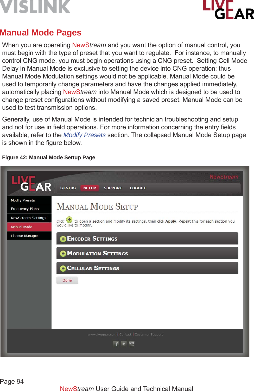
![Page 95NewStream User Guide and Technical ManualLicense Manager PageWhen the License Manager button is selected on the NewStream Web interface, the following licensing details are displayed, as shown in the example Figure 43. To enable newly licensed features, enter the License Key and click the Set Key button. Use the button to refresh the Features lists. The License column displays whether the features are available or not .Licensed FeaturesENG Modulation Features• DVB-T• LMS-T - 10 MHz• LMS-T - 20 MHzSNG Modulation Features [Upgrade Option]• DVB-S QPSK• DVB-S 8PSK/16QAM• DVB-S2 QPSK/8PSK • DVB-S2 16/32 APSK MPEG-2 Encoder Features• MPEG-2 SD - 4:2:0• MPEG-2 SD - 4:2:2• MPEG-2 HD - 4:2:0• MPEG-2 HD - 4:2:2Encryption Features• BISS-1/EInput Features• ASI Remux H.264 Encoder Features• H.264 SD - 4:2:0 [ENG/SNG/CNG]• H.264 SD - 4:2:2 [ENG/SNG]• H.264 HD - 4:2:0 [ENG/SNG/CNG]• H.264 HD - 4:2:2 [ENG/SNG]If NewStream does not have a license for a particular function, the Web interface displays those particular options as not available. If an attempt is made to load a preset that contains the use of a license key which is not enabled, then the NewStream system displays a warning on the LCD. Similarly, if an attempt is made to load a preset that contains use of a license key that is not enabled on the system, within the Web interface, a pop-up displays support information that enables you to call for licensing support. To learn more about feature upgrades please contact LiveGear Support.](https://usermanual.wiki/Microwave-Radio-Communications/NST2G7G/User-Guide-2564620-Page-95.png)
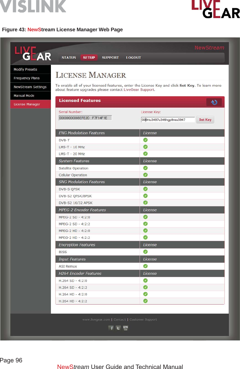
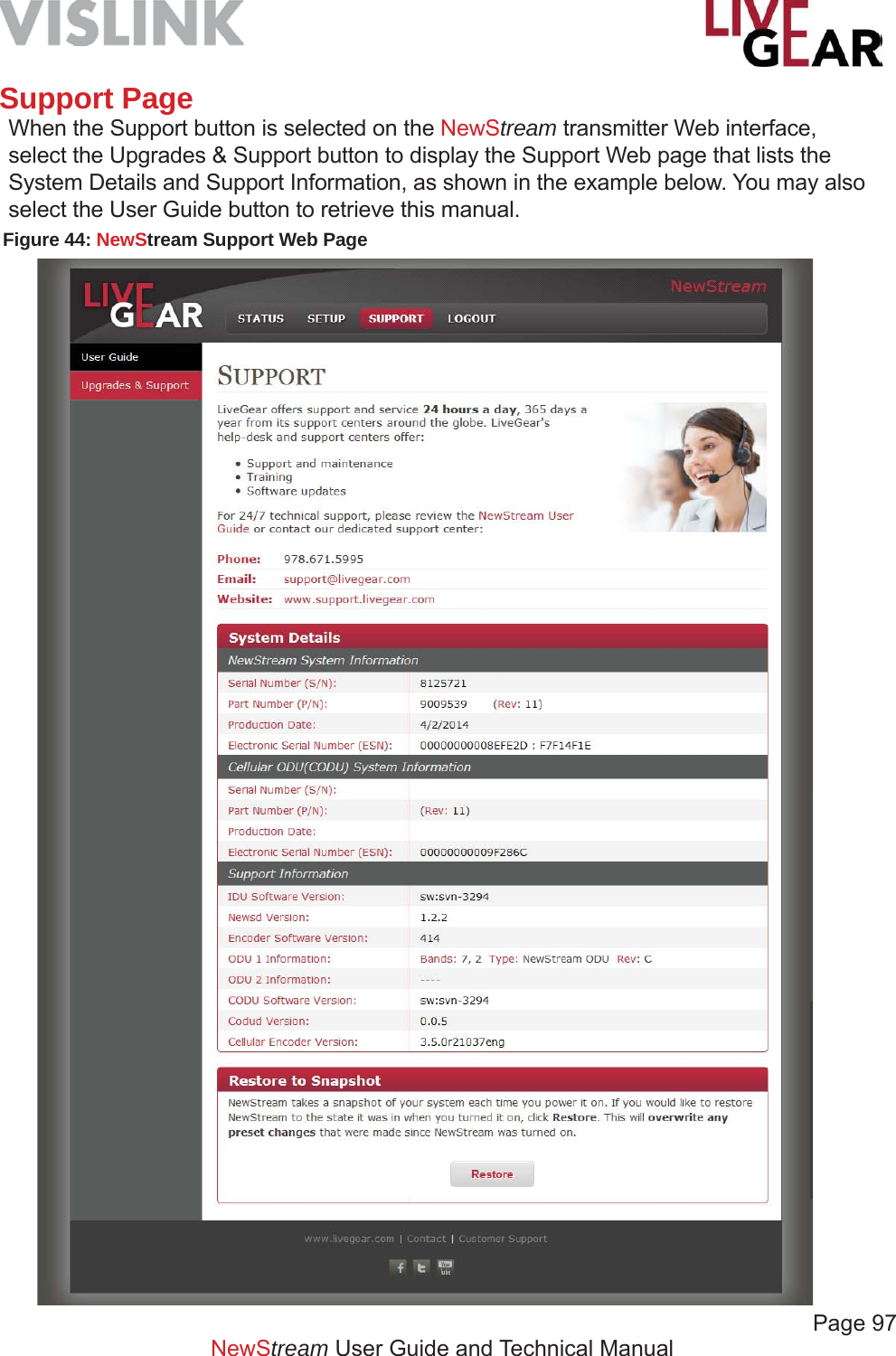
![Page 98 NewStream User Guide and Technical ManualSystem DetailsNewStream System Information• Serial Number [S/N] – displays the serial number that identifi es your NewStream transmitter.• Part Number [P/N] – displays the part number that identifi es your NewStream transmitter.• Production Date – displays the date on which your NewStream was created. • Electronic Serial Number [ESN] – displays the serial number that identifi es your NewStream transmitter.Cellular ODU [CODU] System Information• Serial Number [S/N] – displays the cellular ODU serial number that identifi es your NewStream transmitter.• Part Number [P/N] – displays the cellular ODU part number that identifi es your NewStream transmitter.• Production Date – displays the date on which your NewStream cellular ODU was created. • Electronic Serial Number [ESN] – displays the cellular ODU serial number that identifi es your NewStream transmitter.Support Information• IDU Software Version – displays the software version for your NewStream IDU.• Newsd Version – displays the software version for your NewStream Newsd system.• Encoder Software Version – displays the software version for your NewStream’s encoder.• ODU 1 Information – displays the frequency bands, ODU type and revision for equipment installed on the ODU 1 ports.• ODU 2 Information – displays the frequency bands, ODU type and revision for equipment installed on the ODU 2 ports• Codud Version – displays the software version for your NewStream’s Codud encoder.• Cellular Encoder Version – displays the software version for your NewStream’s cellular encoder.Restore to SnapshotNewStream takes a snapshot of your system each time you apply power to the IDU. If you would like to restore NewStream to the state it was in when you last applied power, click Restore. This will overwrite any preset changes that were made since NewStream was last powered on.](https://usermanual.wiki/Microwave-Radio-Communications/NST2G7G/User-Guide-2564620-Page-98.png)
![Page 99NewStream User Guide and Technical ManualSpecifi cations NewStream ENG CNG SNGOutdoor Unit [ODU]-RF Mast-mounted[single enclosure]Mast-mounted[single enclosure]Optional - Roof-mountedNewSwift, Mantis2-2.5 GHz 8 Watts @ QPSK, 16 QAM N/A N/A4.5-5.0, 6.4-7.1, 6.9-7.5 GHz 5 Watts @ QPSK, 16 QAM N/A N/A12.7-13.25 GHz 1.5 Watts @ QPSK N/A N/ACDMA, UMTS, HSPA+, LTE N/A 6-modems, Bonded N/AIDU to ODU interconnection RG-6/U minimum or better RG-58/U or RG-59/U LMR - 400 or equivalentSize and Weight, ODU 7” W x 10” L x 6” H, 16 lbs. [max. @ 2/7 GHz] 10” W x 14” L x 5” H, 10 lbs. 10” W x 14” L x 5” H, 10 lbsTemperature -20º to +50ºC -20º to +50ºC -20º to +50ºCIndoor Unit [IDU] Rack-mount chassis, singleOperator Controls [5] Programmable OLED [organic light-emitting diode] push-button switches, [2] rocker-style switches, [3] LED push-button switches, [1] On/Off push-button switchDisplays [1] Capacitive color touch TFT 5.0” diagonal 800 x 480 white LED back light display, [2] 16 x 2 segment monochromatic blue OLEDsPresets Up to 99 User-confi gurable 3 Operating Modes-Interview, Standard, Mobility Up to 99 User-confi gurableRear panel I/OBNC- [ASI In, ASI Out, SDI In, CV in, 75 Ω audio, spare]Weidmuller - [analog audio 1L/1R, 2L/2R, digital audio D1, D2, MW ODU power, Ant.]Type N or Triax [ODU 2/7 GHz or 2 GHz and 7 GHz legacy MTX ODUs]Type N- [L-Band Mod. & L-Band Mon.], TNC- [to cellular ODU]Miscellaneous- [1] SMA Wi-Fi, [3] RJ045 Ethernet, [1] 115 VAC IEC C14, [1] DB-9 data, [1] USBSize and Weight, IDU 17.0” W x 16.2” L x 3.5” H [2RUx 19” EIA standard rack-mount], 16 lbs./7.26 kgPrime operating power 115/230 VAC, 2.0 A [typ.]Temperature -10º to +40º CModulation COFDM [DVB-T] OFDMA, CDMA DVB-S QPSK, DVB-S2 QPSKOptional Modulations LMS-T 10/20 N/A DVB-S2 8PSK, 16/32 APSKVideo Input Formats HD/SD-SDIVideo Resolutions HD & SDHigh Defi nition 1080i, 1080p, 720pStandard Defi nition 720 x 480i [NTSC], 720 x 576i [PAL]Video Encoding Profi le MPEG-2, H.264 HD/SD, 4:2:2/4:2:0 H.264 AVC HD/SD 4:2:0 High Profi le @ Level 4.1MPEG-2, H.264 HD/SD, 4:2:2/4:2:0HD Encoding Rate@4:2:2 [MPEG-2] 8.0 to 30 Mbps N/A 8.0 to 80 MbpsHD Encoding Rate@4:2:0 [MPEG-2] 8.0 to 30 Mbps N/A 8.0 to 380 MbpsSD Encoding Rate@4:2:2 [MPEG-2] 2.0 to 50 Mbps N/A 2.0 to 50 MbpsSD Encoding Rate@4:2:0 [MPEG-2] 1.5 to 15 Mbps N/A 1.5 to 15 MbpsHD Encoding Rate@4:2:2 [H.264] 1.5 to 20 Mbps 750 kbps to 10 Mbps 1.5 to 20 MbpsHD Encoding Rate@4:2:0 [H.264] 1.5 to 20 Mbps 128 kbps to 10 Mbps 1.5 to 20 MbpsSD Encoding Rate@4:2:2 [H.264] 1.5 to 15 Mbps 750 kbps to 10 Mbps 1.5 to 20 MbpsSD Encoding Rate@4:2:0 [H.264] 1.5 to 15 Mbps 128 kbps to 10 Mbps 1.5 to 15 MbpsAudio Encoding 2- analog stereo/4-mono, AES/EBU - up to 4 pairs embedded in SDI1-analog stereo/2-mono, AES/ EBU [AAC] - up to 2 pairs embedded in SDI2- analog stereo/4-mono, AES/EBU - up to 4 pairs embedded in SDIAudio Input [Analog] +8 dBm [avg.] @ 600 Ω bal.THD @ 1 kHz TT <0.1% to +18 dBm max. 0.3% to +18 dBm max. <0.1% to +18 dBm max. S/N [Signal to Noise] >66 db RMS >65 db RMS >66 db RMSFrequency Response 0.03-18 KHz ± 1.0 dB 0.03-12 KHz ± 1.0 dB 0.03-18 KHz ± 1.0 dBAES Input [digital] 1.0 V P/P @ 75 Ω unbalanced N/A 1.0 V P/P @ 75 Ω unbalanced](https://usermanual.wiki/Microwave-Radio-Communications/NST2G7G/User-Guide-2564620-Page-99.png)
![Page 100 NewStream User Guide and Technical ManualAppendix A: Microwave and Cellular ODU Confi gurations Microwave ODU Wiring HarnessThe minimum recommended AWG cables are 4-conductor 20 AWG or 2-conductor 16 AWG for new installations, although additional customer-specifi c cables may be required for applications such as mast-lighting, off-air antennas, mast-cams, etc. In addition, NewStream is backwards compatible with legacy CodeRunner CR2 and MTX5000 van transmit Nycoil installations.Selecting Function Cables To select the cables for your wiring harness, select the functions that you require and match the individual cables that are applicable to the particular requirements. These cables should be included in the harness. NewStream provides antenna polarity controls and serial control over the IF interconnect cable plus feed power and polarity for the antenna connection to the ODU or the IDU. For a new installation, the 8 pin connection on the ODU will be used. A short jumper cable can be used for the antenna connection, therefore no cables need to be specifi ed inside the Nycoil conduit for the antenna.NewStream simplifi es the ODU cabling due to the higher voltage [48V] used to power the ODU. The minimum recommended cables are:• 4 conductor 20AWG Type N• 2 conductor 16AWG Type N or• Belden 8232 Triax cableCellular ODU Wiring HarnessThe Cellular ODU uses a single coax type cable - RG59 or RG6 with TNC connectors. Note that both 48 V DC power and data are passed over this coax cable.](https://usermanual.wiki/Microwave-Radio-Communications/NST2G7G/User-Guide-2564620-Page-100.png)
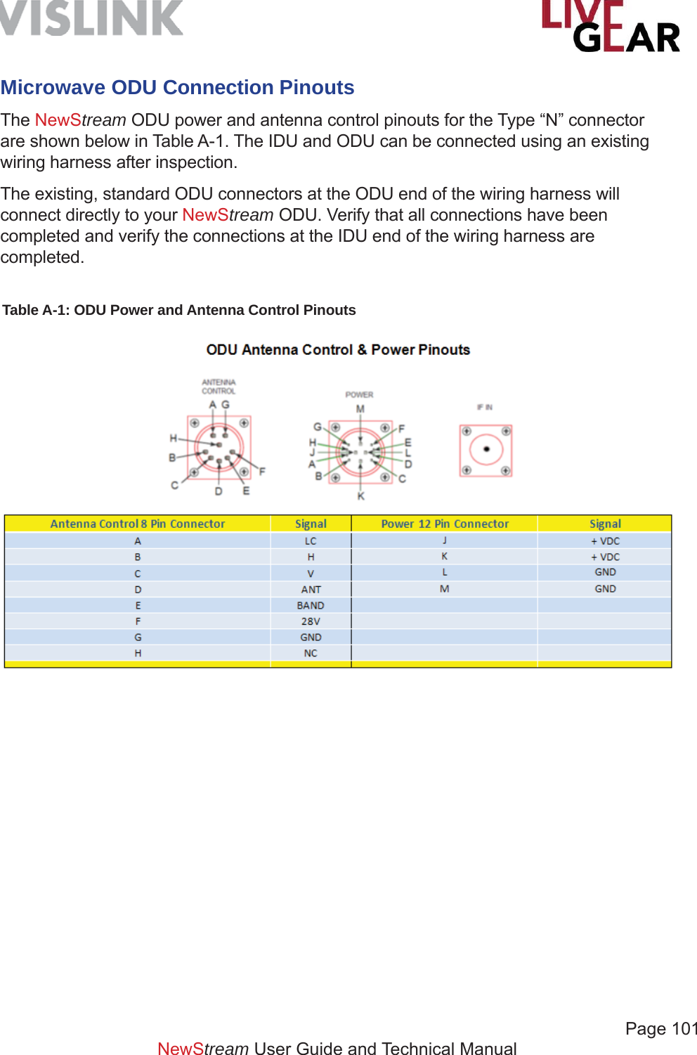
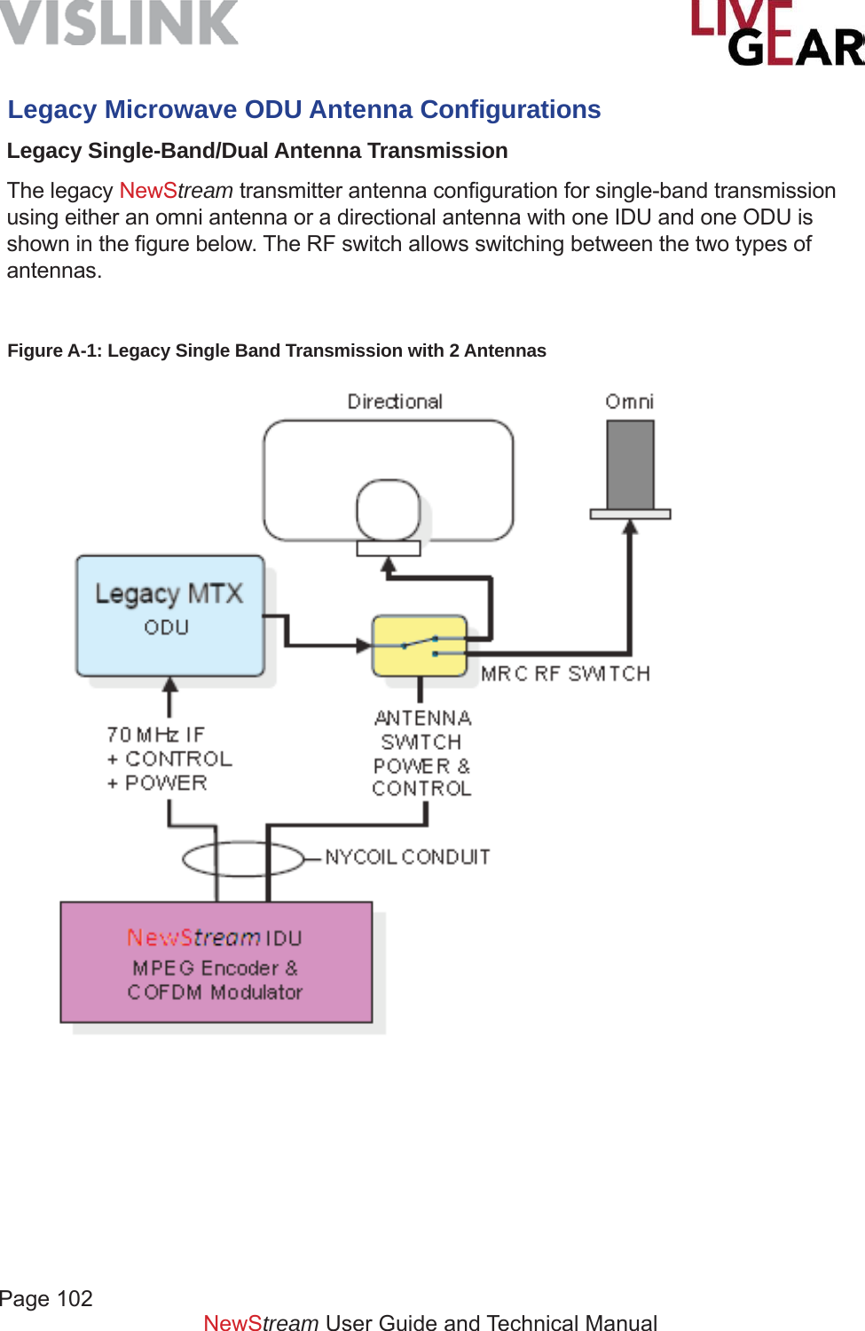
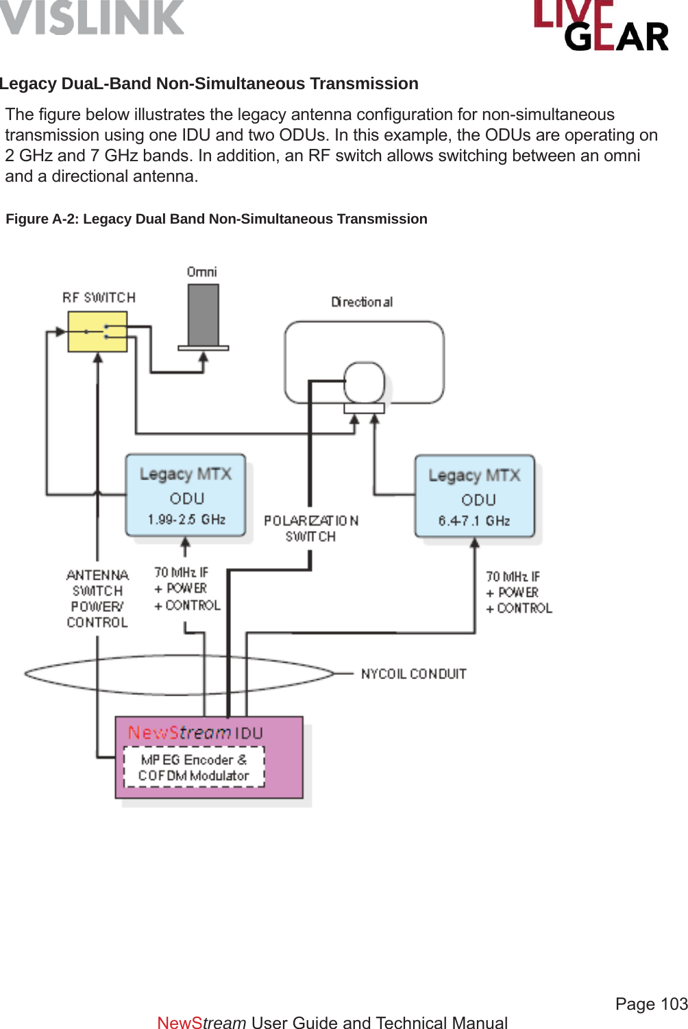
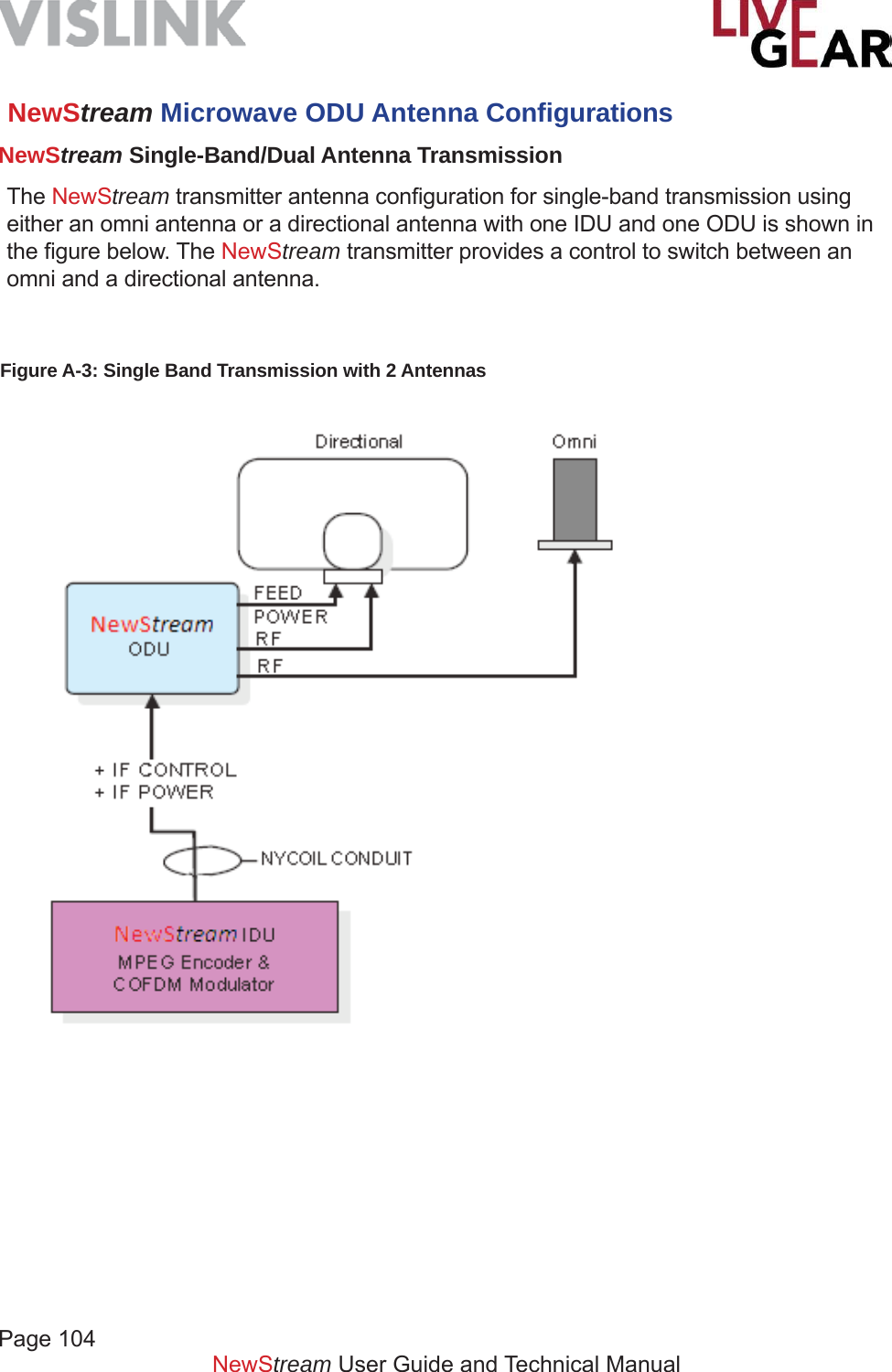
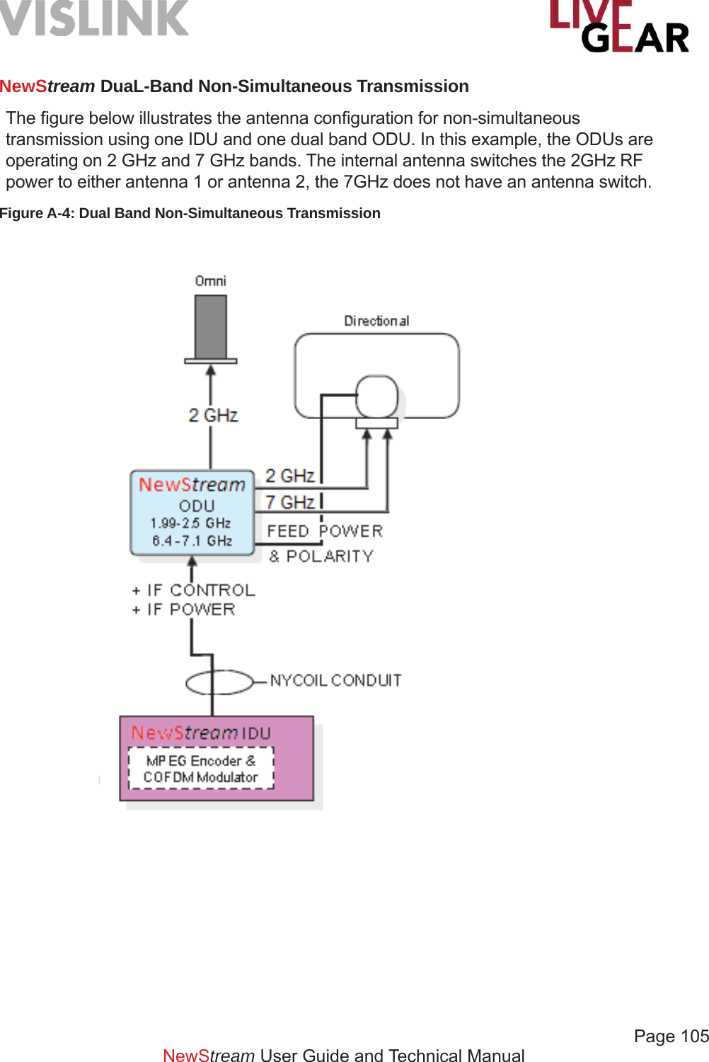
![Page 106 NewStream User Guide and Technical ManualCellular ODU ConnectionsThe NewStream cellular antenna system includes a TNC 75 Ω coaxial connection to the ODU 1 output found on the NewStream rear panel and a series of installation slots for mini-SIM cards [refer to the fi gure below]. Refer to the SIM Application Guide section below for more information. Figure A-5: Cellular ODU ConnectionsSIM Application GuideCellular Wireless Data or SIM cards are a critical component associated with the NewStream transmitter. A Subscriber Identity Module or SIM is an integrated circuit that stores the International Mobile Subscriber Identity [IMSI] and key used to identify and authenticate subscribers on mobile telephony devices.The removable SIM Card can be transferred between different mobile devices. NewStream uses up to six mini-SIM cards which are the same thickness as full-size SIM cards but their length and width are 25 mm × 15 mm [0.98 x 0.59 inches]. For scale, the original SIM card has dimensions that are similar to that of a typical credit card. Refer below to the relative size of the mini-SIM.](https://usermanual.wiki/Microwave-Radio-Communications/NST2G7G/User-Guide-2564620-Page-106.png)
![Page 107NewStream User Guide and Technical ManualA SIM card contains:• its unique serial number [ICC ID] • International Mobile Subscriber Identity [IMSI] • security authentication and ciphering information • temporary information related to the local network • a list of the services the user has access to • two passwords: a personal identifi cation number [PIN] for ordinary use and a personal unblocking code [PUK] for PIN unlocking The primary advantage of cellular wireless data is that you have access to the Internet from any location, indoors or outdoors, throughout your carrier’s data coverage area. A disadvantage – as is prevalent with cellular telephones – is that cellular coverage can be attenuated in remote areas.Figure A-6: SIM Card Sizes](https://usermanual.wiki/Microwave-Radio-Communications/NST2G7G/User-Guide-2564620-Page-107.png)
![Page 108 Figure A-7: Cellular ODU SIM Card Slots CoverSIM Installation SlotsThe Cellular cards or SIMs, are installed in the ports shown below. Be sure to power down NewStream before installing or removing SIM cards.NewStream User Guide and Technical ManualCellular ODU MountingIt is recommended that your NewStream cellular antenna system be installed in a confi guration similar to that shown in Figure A-8. It must not be mounted in front of or beside the microwave antenna and to avoid interference, the microwave system must be powered down before using the cellular equipment. Metallic objects must also be kept at least one foot [30.5 cm] from the sides of the cellular ODU.Figure A-8: Recommended Cellular ODU Mounting Confi guration](https://usermanual.wiki/Microwave-Radio-Communications/NST2G7G/User-Guide-2564620-Page-108.png)
![Page 109 NewStream User Guide and Technical ManualGlossaryTerm Defi nition1080i 1080i is a standard HDTV video format. 1080 represents 1080 lines of vertical resolution and the letter i represents “interlaced” or non-progressive scan. 1080i usually assumes a wide screen aspect ratio of 16:9, implying a horizontal resolution of 1920 pixels and a frame resolution of 1920 x 1080, or 2.07 million pixels.16-QAM 16-state Quadrature Amplitude ModulationThe signal [video + audio] is imposed onto the 70 MHz carrier by varying both the phase and the amplitude of the signal while keeping the frequency constant. There are 16 possible combinations of phase and amplitude that can be used to carry information.3G 3G represents the third generation of mobile telecommunications technology. 3G telecommunication networks support services that provide an information transfer rate of at least 200 kbit/s.4G 4G represents the fourth generation of mobile phone mobile communication technology standards. It is a successor to the third generation [3G] standards. A 4G system provides mobile ultra-broadband Internet access, for example to laptops with USB wireless modems, to smartphones, and to other mobile devices. Conceivable applications include amended mobile web access, IP telephony, gaming services, high-defi nition mobile TV, video conferencing, 3D television, and cloud computing.64-QAM 64-state Quadrature Amplitude ModulationThe signal [video+audio] is imposed onto the 70 MHz carrier by varying both the phase and the amplitude of the signal while keeping the frequency constant. There are 64 possible combinations of phase and amplitude that can be used to carry information. 720p 720 represents 720 lines of vertical resolution and the letter p represents non-interlaced or progressive scan. When broadcast at 60 frames per second, 720p features the highest temporal [motion] resolution possible under the ATSC standard. Progressive scanning reduces the need to prevent fl icker by fi ltering out fi ne details, so spatial [sharpness] resolution is much closer to 1080i than the number of scan lines would suggest.802.11 IEEE 802.11 is a set of medium access control and physical layer specifi cations for implementing wireless local area network [WLAN] computer communication in the 2.4, 3.6, 5 and 60 GHz frequency bands.8-PSK 8-Phase Shift Keying 8-PSK is a digital modulation class that conveys data by changing, or modulating, the phase of a reference signal or carrier wave. AAC - LC Advanced Audio Coding - Low ComplexityAAC is a standardized, lossy compression and encoding scheme for digital audio. Low Complexity [LC] encoding is the simplest and most widely used and supported.](https://usermanual.wiki/Microwave-Radio-Communications/NST2G7G/User-Guide-2564620-Page-109.png)
![Page 110NewStream User Guide and Technical ManualTerm Defi nitionABR Adaptive Bit-rate ABR encoding dynamically adjusts an encoder’s output bit-rate to accommodate available upload speeds across several networks.Aggregation Aggregation refers to the reconstruction and reordering of separate, packetized, video transport streams into a single coherent video stream, as the streams arrive at an IP - addressed destination. As an example, a LiveGear Receiver aggregates video feed from an NewStream transmitter for decoding. Similarly, the VMS-1000 also aggregates a video signal for distribution over the Web.APN Access Point Name APN is a confi gurable network identifi er used by a mobile device when connecting to a GSM carrier. The carrier examines the APN identifi er to determine the network connection type for the NewStream transmitter. The APN determines which IP addresses should be assigned to NewStream, which security methods should be used, and how or if, it should be connected to a private network.ASI Asynchronous Serial InterfaceASI refers to a streaming data format that often carries an MPEG Transport Stream. This serial communications interface operates at up to 270 Mbit/sec. ASI is generally used in fi eld news-gathering operations.Band [RF] This refers to the RF band to which the AirCam is calibrated. To receive RF signals an antenna is used by the AirCam with a radio tuner to adjust to a particular frequency range within the RF band. This tuning is accomplished using a resonator – a circuit with a capacitor and an inductor forming a tuned circuit. The resonator amplifi es oscillations within a particular frequency band, while reducing oscillations at other frequencies outside the band.BAS Broadcast Auxiliary ServiceBER Bit Error RatioThe Bit Error Rate is the percentage of bits that have errors relative to the total number of bits in the signal. The rate is an indication of how often a packet or other data unit has to be retransmitted because of an error.BISS-1 Basic Inter-operable Scrambling System-1BISS is a satellite signal scrambling system. BISS-1 transmissions are protected by a 12 digit hexadecimal session key that is agreed by the transmitting and receiving parties prior to transmission. The key is entered into both the encoder and decoder. The key forms part of the encryption of the digital television signal Any receiver with BISS support and the correct key will be able to decrypt the signal.](https://usermanual.wiki/Microwave-Radio-Communications/NST2G7G/User-Guide-2564620-Page-110.png)
![Page 111NewStream User Guide and Technical ManualTerm Defi nitionBISS-E Basic Inter-operable Scrambling System-EncryptedBISS-E is an variation of the scrambling system where the decoder has stored one secure BISS-key entered by for example, the rights-holder. This key is unknown to the decoder’s user. The user is sent a 16-digit hexadecimal code which is entered as a session key. This session key is then mathematically combined internally to calculate a BISS-1 key that can decrypt the signal.BNC Bayonet lock coaxial connector [Compare to TNC]Bonding The combination of several cellular network channels together creating single, virtual high-speed connection. BUC Block Up-converterA block up-converter [BUC] is used in the transmission [uplink] of satellite signals. It converts a band of frequencies from a lower frequency to a higher frequency. Modern BUCs convert from the L band to Ku band, C band and Ka band. Older BUCs convert from a 70 MHz intermediate frequency [IF] to Ku band or C band.CDMA Modem Code Division Multiple Access ModemA CDMA Modem uses a digital radio system that transmits streams of bits [PN codes]. CDMA permits several radios to share the same frequencies. Unlike TDMA [Time Division Multiple Access], a system used in 2G GSM, all radios can be active all the time, because network capacity does not directly limit the number of active radios. CDMA cellular communication standard is most commonly used in North America.COFDM Coded Orthogonal Frequency-Division Multiplexing COFDM is a method of encoding digital data on multiple carrier frequencies. COFDM is a frequency-division multiplexing [FDM] scheme used as a digital multi-carrier modulation method. It is deemed coded because of the use of forward error correction [FEC]. A large number of closely spaced orthogonal sub-carrier signals are used to carry data on several parallel data streams or channels. Each sub-carrier is modulated with a conventional modulation scheme, such as quadrature amplitude modulation or phase-shift keying, at a low symbol rate, maintaining total data rates similar to conventional single-carrier modulation schemes in the same bandwidth.COFDM-based transmitters with diversity receivers use DVB-T, which was originally designed for high power stationary UHF transmitters fed highly compressed video by rack mount encoders and stationary domestic receivers.Composite [Baseband] A band or grouping of frequencies and/or subcarriers, including video, occupied by the signal in a radio transmission system. Also called Baseband.](https://usermanual.wiki/Microwave-Radio-Communications/NST2G7G/User-Guide-2564620-Page-111.png)
![Page 112NewStream User Guide and Technical ManualTerm Defi nitionDecoder Buffer Length The Decoder Buffer Length is the size of the buffer fed to the decoder when using an audio bitrate_cap, expressed in kbps. The buffer_size divided by bitrate_cap represents the size of the buffer in milliseconds; so if you set bitrate_cap to 1000 and buffer_size to 1000, the buffer is effectively 1.0 second. If bitrate_cap is 500 and buffer_size is 1000, the buffer is 2.0 seconds. This factor is typically used only for streaming [RTMP or broadcast] video, not for HTTP delivery of video. Only use this setting if you understand its implications, as it can decrease video quality. This should typically only be used for streaming [or for device playback].DES Data Encryption StandardDHCP Dynamic Host Confi guration ProtocolA protocol for automating the confi guration of computers that use TCP/IP.Dynamic Host Confi guration Protocol is a network protocol used to confi gure network devices to communicate on an IP network. Internet Protocol addresses are assigned to a host either at the time of booting, or permanently, by fi xed confi guration of its hardware or software. Persistent confi guration is also known as using a Static IP address. In contrast, in situations when the computer’s IP address is assigned newly each time, this is known as using a dynamic IP address. Dynamic Host Confi guration Protocol is a network protocol used to confi gure network devices to communicate on an IP network. A DHCP client uses DHCP protocol to acquire confi guration information, such as an IP address, a default route and one or more DNS server addresses from a DHCP server. The DHCP client then uses this information to confi gure its host. Once the confi guration process is complete, the host is able to communicate on the Internet. DNS Domain Name SystemA DNS Server hosts a network service for providing responses to queries against a directory service. It maps a human-recognizable identifi er to a system-internal, numeric, identifi cation or addressing component. This service is performed by the server according to a network service protocol. The most important function of the DNS Server is the translation or resolution of human-memorable domain names and hostnames into the corresponding numeric Internet Protocol Addresses.DVB-T Digital Video Broadcasting - TerrestrialThis system transmits compressed digital audio, digital video and other data in an MPEG transport stream, using coded orthogonal frequency-division multiplexing [COFDM or OFDM] modulation. DVB-T offers three different modulation schemes: QPSK, 16QAM and 64QAM.FEC Forward Error CorrectionA type of digital signal processing in which a transmitter encodes redundant data bits in a signal and a decoder in a receiver detects any errors and extracts the original signal.FTP File Transfer ProtocolA standard Internet protocol commonly used to transfer fi les from the local computer to a remote web server or to download fi les from a remote server to the local computer.](https://usermanual.wiki/Microwave-Radio-Communications/NST2G7G/User-Guide-2564620-Page-112.png)
![Page 113 NewStream User Guide and Technical ManualTerm Defi nitionGOP In MPEG encoding, a Group of Pictures [GOP] specifi es the order in which intra-frames are arranged. The GOP is a group of successive pictures within an MPEG-coded fi lm and/or video stream. Each MPEG-coded fi lm and/or video stream consists of successive groups of pictures.GSM Modem Global System for Mobile Communications Modem A GSM Modem is a specialized type of modulator/demodulator that accepts a SIM [Subscriber Identity Module] card and operates over a subscription to a mobile operator, as a mobile phone functions. When a GSM modem is connected to a digital device, it uses the GSM modem to communicate over the mobile network. While GSM modems are most frequently used to provide mobile Internet connectivity, many of them can also be used for sending and receiving SMS [Short Message Service (e.g. text message)] and MMS [Multimedia Messaging Service] messages.Guard Interval A method used to prevent interference among distinct transmissions.H.264 H.264/MPEG-4 Part 10 or AVC [Advanced Video Coding] is a standard for video compression and is currently one of the most commonly used formats for the recording, compression and distribution of high defi nition video.HD High Defi nition [video]HD-SDI High Defi nition Serial Data InterfaceA serial communications interface operating at 1.5 Gbit/sec.HSDPA High-Speed Data Packet AccessHSPA+ Evolved High-Speed Data Packet AccessIFB Interruptible foldback [IFB], is an intercom cueing system used to monitor and intercede in television and radio broadcasts, public speaking, fi lm and video production and other such endeavors. The IFB intercom circuit consists of a mix-minus program feed sent to a presenter’s wired or wireless in-ear monitors [IEMs] through a telephone or radio receiver. This feed can be interrupted and replaced by a producer’s or director’s intercom microphone. For example, on a television news program, a producer can talk to the news anchors, to tell them when they are live on the air and to begin reading the news, or when to take a break.In electronic news gathering [ENG], IFB transmission can be sent through a telephone hybrid, the station’s Multi-channel Television Sound [MTS] PRO channel during live remote broadcasts, or through some other return link in a broadcast auxiliary service. All signals arrive on site with a time delay as they travel through a wire, or during the conversion to radio frequency and then back to electronic audio, or in the conversion from analog to digital signal and back again to the analog realm. To achieve the mix-minus program to the IFB, certain audio elements that originate remotely from the mix point will be eliminated from the mix sent back to the remote site to avoid an echo.](https://usermanual.wiki/Microwave-Radio-Communications/NST2G7G/User-Guide-2564620-Page-113.png)
![Page 114NewStream User Guide and Technical ManualTerm Defi nitionIMEI The International Mobile Station Equipment Identity [IMEI] number is used to identify 3GPP [i.e., GSM, UMTS and LTE]. The IMEI number is used by the GSM network to identify valid devices and has no permanent relation to the subscriber. The subscriber is identifi ed by transmission of an IMSI number; stored on the SIM card.IP Address An Internet Protocol [IP] address is a 32-bit number [for example, 123.45.67.89 for IP version 4] or a 128-bit number [for IP version 6] that identifi es the network device that is sending or receiving information that is transmitted across a local area network [LAN] or the Internet.LAN Local Area Network [LAN] is a network that provides data communications to users within a confi ned geographic area such as a building or complex of buildings; TCP/IP is the typical transport protocol.LMS-T Link Modulation Scheme -Terrestrial This modulation type has been designed specifi cally to allow the data bandwidth required for contribution with more effi cient error correction and more effective use of spectrum. LMS-T is particularly suited for rapidly changing channels, so it can be at the higher frequencies 6,7,8 GHz and at higher speeds, where DVB-T is compromised. LMS-T has been used at 574km/h [356mph] on the French TGV, while setting the train speed record.LQ Link Quality is a feature provided in COFDM receivers that analyzes signal-to-noise ratio and other important digital signal parameters as supplied by the COFDM demodulator circuit. The Link Quality feature calculates an integer value from 0 [no signal] to 9 [highest possible quality].LTE Long Term Evolution LTE is a standard for wireless data communications technology and an evolution of the GSM/UMTS standards. The goal of LTE was to increase the capacity and speed of wireless data networks using new DSP [digital signal processing] techniques and modulations that were developed around the turn of the millennium. A further goal was the redesign and simplifi cation of the network architecture to an IP-based system with signifi cantly reduced transfer latency compared to the 3G architecture. The LTE wireless interface is incompatible with 2G and 3G networks, so that it must be operated on a separate wireless spectrum.MAC Address [BSSID] The Media Access Control Address The MAC Address is a unique identifi er assigned to network interfaces, such as the NewStream transmitter, for communications on the physical network segment. A Wi-Fi Access Point’s MAC address is used as the identifi er of a Basic Service Set [BSSID]. The MAC address of the NewStream IDU is also the BSSID for the wireless access point. When prompted, NewStream’s connection information retrieval returns the MAC address and BSSID of the Wi-Fi client, which is displayed in this fi eld.MIMO Multiple-Input and Multiple-OutputMPEG Moving Picture Experts GroupA working group of ISO that establishes standards for digital video and audio compression.](https://usermanual.wiki/Microwave-Radio-Communications/NST2G7G/User-Guide-2564620-Page-114.png)
![Page 115 NewStream User Guide and Technical ManualTerm Defi nitionNTSC National Television System CommitteeColor television standard used in the US. Provides 525 horizontal lines of resolution. Not compatible with PAL or SECAM.OFDM Orthogonal frequency-division multiplexing [OFDM] is a method of encoding digital data on multiple carrier frequencies. OFDM has developed into a popular scheme for wideband digital communication, whether wireless or over copper wires, used in applications such as digital television and audio broadcasting, DSL Internet access, wireless networks, powerline networks, and 4G mobile communications.OFDM is a frequency-division multiplexing [FDM] scheme used as a digital multi-carrier modulation method. A large number of closely spaced orthogonal sub-carrier signals are used to carry data on several parallel data streams or channels. Each sub-carrier is modulated with a conventional modulation scheme [such as quadrature amplitude modulation or phase-shift keying] at a low symbol rate, maintaining total data rates similar to conventional single-carrier modulation schemes in the same bandwidth.The primary advantage of OFDM over single-carrier schemes is its ability to cope with severe channel conditions [for example, attenuation of high frequencies in a long copper wire, narrowband interference and frequency-selective fading due to multipath] without complex equalization fi lters. Channel equalization is simplifi ed because OFDM may be viewed as using many slowly modulated narrowband signals rather than one rapidly modulated wideband signal. The low symbol rate makes the use of a guard interval between symbols affordable, making it possible to eliminate intersymbol interference [ISI] and utilize echoes and time-spreading [on analogue TV these are visible as ghosting and blurring, respectively] to achieve a diversity gain, i.e. a signal-to-noise ratio improvement. This mechanism also facilitates the design of single frequency networks [SFNs], where several adjacent transmitters send the same signal simultaneously at the same frequency, as the signals from multiple distant transmitters may be combined constructively, rather than interfering as would typically occur in a traditional single-carrier system.PAL Phase Alternation LineColor television standard used in many European countries. Provides 625 horizontal lines of resolution. Not compatible with NTSC or SECAM.PCM Pulse-Code Modulation PCM is a method used to digitally represent sampled analog signals. It is the standard form of audio in digital applications. The amplitude of the analog signal is sampled regularly at uniform intervals; each sample is quantized to the nearest value within a range of digital steps. PCM streams have two basic properties that determine their fi delity to the original analog signal: • the sampling rate, • the number of times per second that samples are taken; • the bit depth, which determines the number of possible digital values that each sample can take.](https://usermanual.wiki/Microwave-Radio-Communications/NST2G7G/User-Guide-2564620-Page-115.png)
![Page 116NewStream User Guide and Technical ManualTerm Defi nitionPCR Program Clock ReferenceTo enable a decoder to present synchronized content, such as audio tracks matching the associated video, at least once each 100 millisecond, a Program Clock Reference [PCR] is transmitted in the adaptation fi eld of an MPEG-2 transport stream packet. The PID with the PCR for an MPEG-2 program is identifi ed by the PCR_PID value in the associated Program Map Table. The value of the PCR is employed to generate a system_timing_clock in the decoder. The STC or System Time Clock decoder provides a highly accurate time base that is used to synchronize audio and video elementary streams. Timing in MPEG2 uses this clock as a reference. PES Packetized Elementary StreamPES is a specifi cation in the MPEG-2 parameter that defi nes carrying of elementary streams [usually the output of an audio or video encoder] in packets within MPEG program stream and MPEG transport stream. The elementary stream is packetized by encapsulating sequential data bytes from the elementary stream inside PES packet headers.PID Packet IDEach table or elementary stream in a transport stream is identifi ed by a 13-bit packet ID [PID]. A demultiplexer extracts elementary streams from the transport stream in part by looking for packets identifi ed by the same PID. In most applications, time-division multiplexing is used to decide how often a particular PID appears in the transport stream.PMT Program Map TableA PMT contains information about programs. For each program, there is one PMT. While the MPEG-2 standard permits more than one PMT section to be transmitted on a single PID, most MPEG-2 users such as ATSC and SCTE require each PMT to be transmitted on a separate PID that is not used for any other packets. The PMTs provide information on each program present in the transport stream, including the program_number, and list the elementary streams that comprise the described MPEG-2 program. There are also locations for optional descriptors that describe the entire MPEG-2 program, as well as an optional descriptor for each elementary stream. Each elementary stream is labeled with a stream_type value.QPSK Quadrature Phase-Shift KeyingPhase-shift keying [PSK] is a digital modulation scheme that conveys data by changing, or modulating, the phase of a reference signal or carrier wave. Quadrature Phase-Shift Keying [QPSK] transmits twice the data rate in a given bandwidth compared to Binary Phase-Shift Keying [BPSK] - at the same Bit Error Rate [BER]. The engineering penalty that is paid is that QPSK transmitters and receivers are more complicated than the ones for BPSK. However, with modern electronics technology, the penalty in cost is very moderate. QPSK is also known as 4 - QAM. Roll-off Roll-off describes the steepness of a transmission function with frequency, in connection with fi lter circuits in the transition between a passband and a stop band. It is most typically applied to the insertion loss of the network. It is usual to measure roll-off as a function of logarithmic frequency, consequently, the units of roll-off are either decibels per decade [dB/decade], where a decade is a 10-times increase in frequency, or decibels per octave [dB/8ve], where an octave is 2-times increase in frequency.](https://usermanual.wiki/Microwave-Radio-Communications/NST2G7G/User-Guide-2564620-Page-116.png)
![Page 117 NewStream User Guide and Technical ManualTerm Defi nitionRoll-off [Continued] The concept of roll-off stems from the fact that in many networks roll-off tends towards a constant gradient at frequencies well away from the cut-off point of the frequency curve. Roll-off enables the cut-off performance of such a fi lter network to be reduced to a single number. Note that roll-off can occur with decreasing frequency as well as increasing frequency, depending on the band form of the fi lter being considered. For instance, a low-pass fi lter will roll-off with increasing frequency, but a high-pass fi lter or the lower stop band of a band-pass fi lter, will roll-off with decreasing frequency. RSSI Receiver Signal Strength Indicator [relative]This parameter provides each cellular card’s or Wi-Fi Access Point’s RSSI. The RSSI is the relative received signal strength in arbitrary units. RSSI is an indication of the power level being received by the antenna. The higher the RSSI number, the stronger the signal.SCM-Q Superposition Coded Modulation - QuadratureSCM-Q is a modulation scheme designed to use the bandwidth effi cient codec, such as H.264, enabling the transfer of the same video quality at up to twice the distance, with a greatly improved Peak-to-Average-Power-Ratio [PAPR]. SCM-Q has variable bandwidth so can also be used for channel sharing.SDI Serial Digital InterfaceA serial communications interface operating at 270 Mbit/sec. SDI can operate at 1.5 Gbit/sec for HD.SIM Card Subscriber Identity Module CardA SIM is an integrated circuit that stores the International Mobile Subscriber Identity [IMSI] and key used to identify and authenticate subscribers on mobile telephony devices. A SIM card contains:• its unique serial number [ICC ID] • International Mobile Subscriber Identity [IMSI] • security authentication and ciphering information • temporary information related to the local network • a list of the services the user has access to • two passwords: a personal identifi cation number [PIN] for ordinary use and a personal unblocking code [PUK] for PIN unlocking The primary advantage of cellular wireless data is that you have access to the Internet from any location, indoors or outdoors, throughout your carrier’s data coverage area. A disadvantage – as is prevalent with cellular telephones – is that cellular coverage can be attenuated indoors, as well as in remote areas.SMPTE Society of Motion Picture and Television EngineersSNR Signal-to-Noise RatioA measure of signal strength and quality that is defi ned as the ratio of the amplitude of a signal compared to the amplitude of the background noise. SNR is typically measured in decibels [dB].](https://usermanual.wiki/Microwave-Radio-Communications/NST2G7G/User-Guide-2564620-Page-117.png)
![Page 118 NewStream User Guide and Technical ManualTerm Defi nitionSSID Service Set Identifi erThe SSID is a case-sensitive, alphanumeric, 32 - character unique identifi er attached to the header of packets sent over a wireless local-area network [WLAN] that acts as a password when a mobile device attempts to connect with a Basic Service Set [BSS] which is a component of the IEEE 802.11 WLAN architecture. An SSID is also referred to as a Network Name because essentially it is a name that identifi es a wireless network.The SSID differentiates one WLAN from another, so all Access Points and all devices attempting to connect to a specifi c WLAN must use the same SSID to enable effective roaming. As part of this association process, a wireless client must have the same SSID as that entered in the Access Point or it will not be permitted to join the BSS.Subnet Mask A sub-network, or subnet, is a logically visible subdivision of an IP Network. All computers that belong to a subnet are addressed with a common, identical, most-signifi cant bit-group in their IP address. This results in the logical division of an IP address into two fi elds: a network or routing prefi x and the rest fi eld or host identifi er. The rest fi eld is an identifi er for a specifi c host or network interface. Special gateways called routers exchange traffi c between sub-networks. Such routers constitute the logical or physical boundaries between the subnets.Symbol Rate Symbol Rate [aka baud or modulation rate] is the number of symbol changes [i.e. waveform changes or signalling events] made to the transmission medium per second using a digitally modulated signal or a line code. The Symbol rate is measured in baud [Bd] or symbols/second. In the case of a line code, the symbol rate is the pulse rate in pulses/second. Each symbol can represent or convey one or several bits of data. The symbol rate is related to, but should not be confused with, the gross bitrate expressed in bits/second.TCP/IP Transmission Control Protocol/Internet ProtocolTransmission Control Protocol is a connection-oriented Internet protocol requiring synchronization between the end units [source and destination] for handshaking purposes for guaranteed message delivery that is transmitted over the Internet Protocol, which is the low-level protocol of most internet hardwareTNC Threaded Neill–Concelman A TNC connector is a threaded version of the BNC connector. The connector has a 50 Ω impedance and operates best in the 0 to 11 GHz frequency spectrum. It has better performance than the BNC connector at microwave frequencies.WAN Wide Area NetworkA network provided by telephone and cell phone companies to provide data communications to users over a large geographic area.WLAN Wireless [Wi-Fi] Local Area NetworkA Wireless Local Area Network links two or more devices using some wireless distribution method and usually providing a connection through an access point to the wider Internet. This provides the mobility to move around within a local coverage area and still be connected to the network. Most modern WLANs are based on IEEE 802.11 standards, marketed under the Wi-Fi brand name.](https://usermanual.wiki/Microwave-Radio-Communications/NST2G7G/User-Guide-2564620-Page-118.png)
![Page 120NewStream User Guide and Technical ManualSupport for Your Vislink Product You can contact the Vislink Technical Support staff as follows:24-hour Worldwide Customer SupportE-mail: ussupport@vislink.comTelephone: +1 978-671-5929, +1 978-671-5995 or888-777-9221 In the US or CanadaThe following contact numbers are also available for LiveGear equipment:• 978.671.5700 Press #3• 800.490.5700 Press #3When you contact Technical Support, include the following information: Model number and serial number of the unit [located on a label on the units]. Approximate purchase date.There are no supported fi eld repairs for this product. Return the unit for factory repair.NOTE: If you attempt fi eld repair, you risk damaging your equipment. If your equipment is under warranty, you may also affect your warranty coverage.](https://usermanual.wiki/Microwave-Radio-Communications/NST2G7G/User-Guide-2564620-Page-120.png)