Microwave Radio Communications ODU7ATXAD 7GHz MTX Radio User Manual MTX User and Tech
Microwave Radio Communications LLC 7GHz MTX Radio MTX User and Tech
Contents
- 1. Manual Part 1
- 2. Manual Part 2
Manual Part 1
MTX5000
Manual Part No. 400591-1 Rev. A June 2009
User and Technical Manual
Transmitter System

NOTE TO USER iMTX5000 User and Technical Manual
NOTE TO USER
Overview
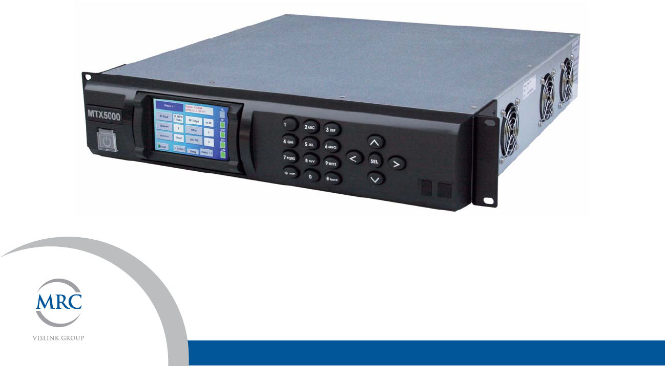
The MTX5000 Transmitter System (MTX5000) is a state-of-the-
art transmitter system. The MTX5000 Indoor Unit (IDU) contains
a central processor used to control all functions and operations
of the system. To avoid potential software hang-ups or software
corruption, please read and follow the guidelines contained in
the following paragraphs.
Avoid Potential Operational
Problems
Information contained in the following paragraphs identify
potential problems that can be avoided by reading and following
the operating procedures provided in this manual.
To avoid potential operational problems, please review the
information contained in the “Routine Operation” Chapter on
page 3-1. The Routine Operation Chapter contains step-by-step
procedures that, when performed correctly, will eliminate
potential problems that could be caused by operator error or by
lack of experience with the MTX5000 system.
Radio Unable to Transmit or Generally Unstable
• If the radio is unable to transmit or is generally unstable,
perform “Select Preset” on page 3-24 to select or re-
select the proper Preset. Then verify proper transmitter
operation by transmitting and receiving.
• If the radio remains unstable, it may be necessary to cycle
power off and on. See ”Powering the MTX5000 System”
on page 3-7 to power down and power up the MTX5000.
Always wait a minimum of 10 seconds between
powering the radio down and then powering the radio
up again.
• After cycling power to off and back to on, perform “Select
Preset” on page 3-24 to select the proper Preset. Then
verify proper transmitter operation by transmitting and
receiving.
• If the radio is still unable to transmit or remains unstable,
contact MRC Technical Support for assistance.
Improper Power Up/Power Down
If the radio is unable to transmit, is unstable, or if the software
appears to be corrupted, the Preset may have been selected or
changed too soon after power was applied or the wrong Preset
was selected.
• Always wait a minimum of 5 seconds after the Main
screen is displayed following power up before selecting a
Preset.
• If the wrong Preset is selected, you must wait a minimum
of 5 seconds before attempting to select another Preset.
Failure to wait 5 seconds minimum between Preset
selections will cause software hang-ups.
If the radio is unable to transmit, is unstable, or if the software
appears to be corrupted, power to the radio may have been
removed and reapplied too quickly.
The MTX5000 central processor requires a minimum of 10
seconds to properly shutdown to avoid possible software
corruption.

NOTE TO USER iiMTX5000 User and Technical Manual
• Software corruption can occur if the external input power
to the radio was momentarily lost and was then reapplied
without waiting a minimum of 10 seconds between loss of
power and reapplication of input power.
• The problem may also occur if the power switch was
pressed to off and back to on without waiting a minimum
of 10 seconds.
• To avoid problems, always wait a minimum of 10
seconds between removal or loss of power and
reapplication of power to the radio.
• The problem may also occur if the progress bar was
displayed when power was removed from the radio.
Always ensure the progress bar is not displayed on
the color LCD display panel when power is removed
from the radio.
If this problem has occurred, press the power switch to off, wait
10 seconds minimum, and press the power switch to on. The
internal processor will attempt to perform a self-recovery of the
software.
• During the software recovery attempt, a progress bar will
be displayed on the color LCD display panel indicating the
progress of the process. This progress bar will take more
time to reach 100% than during a normal power up.
•Do not become impatient during the software
recovery process due to the time it may take for
recovery. Do not remove and reapply power while the
progress bar is displayed during the software self-
recovery process. Software corruption will occur!
• When the power up is complete and the Main screen is
displayed on the color LCD display panel, verify proper
transmitter operation by transmitting and receiving.
• If the software is corrupted and the Main screen is not
displayed, contact MRC Technical Support for assistance.
Radio State Incorrect
If the radio state is incorrect, the correct Preset may not have
been selected. Select the proper Preset per “Select Preset” on
page 3-24.
PA Voltage Adjust Setup Software Hang-up
When performing “Perform PA Voltage Adjust Setup” on page 3-
44, ensure the Outdoor Unit (ODU) is properly connected to the
IDU. If the ODU is not connected to the IDU and you attempt to
perform this procedure, the software will hang up.
•To avoid software hang-up, always ensure the ODU is
connected to the IDU when performing the PA Voltage
Adjust Setup procedure.
• Check the Main screen ODU status indicator. If a major
fault exists in the ODU, do not perform the PA Voltage
Adjust Setup procedure until the fault has been corrected
or until the ODU is connected to the IDU.
• If the ODU is not connected to the IDU or if the ODU has
suffered a failure, the PA Voltage Adjust Setup Screen will
remain displayed on the color LCD display panel if the PA
Voltage Adjust Setup screen Start option button is
selected.
If the software hangs up due to the ODU not being connected to
the IDU or if the ODU has failed, perform the following:
• Press the power switch to off.
• Connect the ODU to the IDU or go to “Troubleshooting”
on page 4-1 to correct the fault.

NOTE TO USER iiiMTX5000 User and Technical Manual
• Press the power switch to on, perform “Select Preset” on
page 3-24 to select the proper Preset.
•“Perform PA Voltage Adjust Setup” on page 3-44 and then
verify proper transmitter operation by transmitting and
receiving.
RF Levels Too High
If the transmitted RF levels are too high, “Perform RF Level
Adjust” on page 3-49.
Software Recovery
If the software becomes corrupted, the MTX5000 IDU will
attempt to self-recover the software. During the software self-
recovery, the previously configured parameters may be
recovered - not the latest parameters. This may happen if a fault
occurs when installing software updates.
If the software becomes corrupted, press the power switch to off,
wait 10 seconds minimum, and press the power switch to on.
The internal processor will attempt to perform a self-recovery of
the software.
• During the software recovery attempt, a progress bar will
be displayed on the color LCD display panel indicating the
progress of the recovery process. This progress bar may
take considerably more time to reach 100% than during a
normal power up.
• Do not become impatient during the software
recovery process due to the time it may take for
recovery. Do not remove and reapply power while the
progress bar is displayed during the software
recovery process. Software corruption will occur!
• When the power up is complete and the Main screen is
displayed on the color LCD display panel, you may need
to perform “Select Preset” on page 3-24. Then verify
proper transmitter operation by transmitting and receiving.
If the software is no longer corrupted, perform “Firmware
Update” on page 5-114 to verify that you have the latest software
installed in your MTX5000 IDU. Update the software, as
required.
If the software is corrupted or if the Main screen is not displayed,
contact MRC Technical Support for assistance.
Color Bar Generator Operations
All MTX5000 Indoor Units (IDU) contain a built-in digital Color
Bar Generator (CBG) as standard equipment. The IDU is also
available with an optional analog CBG. Potential operator
problems can occur when using the optional analog CBG or the
built-in digital CBG.
Potential operator-induced problems may include the following:
• Selection of the CBG On operating mode during test,
troubleshooting, or CBG setup and failure to select the
Off, A Gen, or A Stby operating mode for normal
operation when test, troubleshooting, or CBG setup is
completed.
• Selection of the CBG On, A Gen, or A Stby operating
mode when the optional Analog Color Bar Generator is
not installed in the MTX5000 IDU.
To avoid potential operator problems that can impact operation
of the MTX5000 System, the following information is provided:
• The optional analog CBG and the digital CBG both
include Off, On, A Gen (Auto Generated), or A Stby
(Auto Standby) operating mode options.
• The CBG mode should only be set to the On operating
mode for test, troubleshooting, or for setup of the

NOTE TO USER ivMTX5000 User and Technical Manual
applicable Color Bar Generator.
• During normal operation, the CBG Off, A Gen, or A Stby
operating mode must be selected for proper operation
and video transmission.
• CBG operating modes are not Preset-specific or mode-
specific. If your IDU contains the optional analog CBG
and you select the Off, A Gen, or A Stby operating mode
for an analog Preset, the selected option is applicable for
all analog Presets, as well as for all digital Presets.
• If the CBG On operating mode is selected, the output of
the MTX5000 IDU will be color bars only, not video,
regardless if an analog or a digital Preset is selected.
When color bars are set to On (enabled), color bars take
priority over all analog and digital Preset settings.
• If the IDU output consists of color bars only, please verify
that the analog and/or digital CBG operation mode is not
set to On before you call customer service. The problem
may be nothing more than having selected the On
operating mode.
Perform “Select Color Bar Generator Mode” on page 3-52
to select the Off, A Gen, or A Stby operating mode.
• It is possible to select analog CBG options if you do not
have the optional CBG installed in your MTX5000 IDU,
but the options are not active and will result in
transmission problems.
•Be careful when setting CBG options if you do not
have the optional analog CBG installed.
• If you attempt to set the CBG operating mode to On, A
Gen, or A Stby and you do not have the optional analog
CBG installed in your MTX5000 IDU, you will have a blank
screen displayed for analog Presets. Before calling
Customer Service, please verify that the analog CBG
operating mode has not been set to On.
Go to “Select Color Bar Generator Mode” on page 3-52
and select the Off, A Gen, or A Stby operation mode.
• When utilizing a digital Preset with an ASI video input and
the digital CBG option setting is A Gen or A Stby, loss of
the ASI video input will not display color bars or will not
change the MTX5000 IDU operation to standby indicating
loss of the ASI signal. This is normal operation for ASI
video loss.
Using the Color LCD Display Panel Touch Screen
CAUTION Avoid damage to the color LCD display
panel!
The color LCD display panel touch screen
may be damaged if a sharp, hard-pointed
object, such as a pencil or a pen, is used to
select the displayed options.
Touch screen options must only be selected
using your fingers, a soft-pointed stylus, or
the front panel function keys.
Damage to the color LCD display panel
caused by using a hard-pointed object or
other misuse may void your warranty on
the MTX5000 IDU.
Whenever you use the MTX5000 IDU color LCD display panel

NOTE TO USER vMTX5000 User and Technical Manual
touch screen to select options, use care to avoid damage.
Sharp-pointed objects or excessive force can render the color
LCD display Panel touch screen inoperable.
Use your fingers, a soft-pointed stylus, or the front panel function
keys to select the displayed options. A cotton swab works very
well as a soft-pointed stylus.
Remote Location Operations
It is highly recommended that remote operations be performed
using a Microsoft Windows-based PC that meets the following
requirements:
• Microsoft Windows XP Operating System with SP2
• 1.2 GHz processor
• 500 MB of system memory
• 1.0 Gb of free hard disk space
• Super VGA 800 x 600 pixels
• Internet Explorer 7.0 or later
Remote location operations must be performed using
Internet Explorer 7.0 or later.
Note When operating in the remote mode, if the web
page on the PC display should become blank when
switching between option tabs, select the web
browser refresh option. The correct screen will
then be displayed
Ethernet Connections
If you are connected to the Ethernet via the IDU rear panel
ETHERNET RJ45 connector and you find that the color LCD
display panel appears to be operating very slowly or has locked
up completely, disconnect the Ethernet cable from the
ETHERNET connector.
This should free up the color LCD display Panel and the IDU
should resume operating properly.
Notes

NOTE TO USER viMTX5000 User and Technical Manual

NOTE TO USER viiMTX5000 User and Technical Manual

NOTE TO USER viiiMTX5000 User and Technical Manual

Notices
Notices Notices-iMTX5000 User and Technical Manual
Notices
About This Manual
Part number 400591-1
Revision A June 2009
MTX5000 Transmitter System (MTX5000)
Copyright
The information contained in this manual remains the property of
Microwave Radio Communications (MRC) and may not be used,
disclosed, or reproduced in any form whatsoever, without the
prior written consent of MRC.
MRC reserves the right to make changes to equipment and
specifications of the product described in this manual at any time
without notice and without obligation to notify any person of such
changes.
© 2009 Microwave Radio Communications
Microwave Radio Communications
101 Billerica Avenue - Bldg. 6
North Billerica, MA 01862-1256 USA
TEL: 800.490.5700
+1.978.671.5700
Printed in U.S.A.
The Microwave Radio Communications and Vislink trademarks
and other trademarks are registered trademarks in the United
States and/or other countries.
Microsoft®, Windows®, and Internet Explorer® are registered
trademarks of Microsoft Corporation in the United States and/or
other countries.
Grainger® is a registered trademark of W.W. Grainger, Inc., in
the United States and other countries.
McMaster® is a registered trademark of McMaster-Carr Supply
Company in the United States and other countries.
Do It Best ® is a registered trademark of DoitBest.com or its
affiliate, Do It Best Corp., in the United States and other
countries.
Proprietary Material
The information and design contained within this manual was
originated by and is the property of MRC. MRC reserves all
patent proprietary design, manufacturing, reproduction use, and
sales rights thereto, and to any articles disclosed therein, except
to the extent rights are expressly granted to others. The
foregoing does not apply to vendor proprietary parts.
MRC has made every effort to ensure the accuracy of the
material contained in this manual at the time of printing. As
specifications, equipment, and this manual are subject to change
without notice, MRC assumes no responsibility or liability
whatsoever for any errors or inaccuracies that may appear in this
manual or for any decisions based on its use. This manual is
supplied for information purposes only and should not be
construed as a commitment by MRC.
Quality Certification
Microwave Radio Communications is certified to ISO 9001:2000.

Notices Notices-iiMTX5000 User and Technical Manual
Changes or modifications not expressly approved by MRC could
void the user’s authority to operate the equipment.
General Safety Information
The following safety requirements, as well as local site
requirements and regulations, must be observed by personnel
operating and maintaining the equipment covered by this manual
to ensure awareness of potential hazards.
WARNING - RF Power Hazard
High levels of RF power are present in the unit. Exposure to RF
or microwave power can cause burns and may be harmful to
health.
Remove power from the unit before disconnecting any RF cables
and before inspecting damaged cables and/or antennas.
Avoid standing in front of high gain antennas (such as a dish
antenna) and never look into the open end of a waveguide or
cable where RF power may be present.
RF Exposure - Safe Working Distances
MRC provides this warning for safety purposes with the intent to
inform the user of the potential hazard to RF exposure. The
following guidelines for safe operation were derived from OET
bulletin 65, August 1997, as recommended by the Federal
Communications Commission (FCC).
The MTX5000 Transmitter System is a mobile transmitter
system designed to provide services to broadcast ENG users
under CFR 74 subpart F and 74.601 TV pickup stations. This
unit, operated without an antenna, will not create RF energy
exceeding 1.0 mW/cm2, the FCC limit for exposure. Once
connected to an antenna, the potential for harmful exposure will
be greatly enhanced.
In this situation, a certain distance from the radiator is to be
maintained. Calculations need to be performed to understand
what that safe margin for exposure is. This is known as the
Maximum Permissible Exposure (MPE) limit.
Note Hazardous RF radiation limits and recommended
distances may vary by country. Ensure that all
applicable state and federal regulations are
observed when using this transmitter.
Calculations provided are for common antennas often utilized in
the ENG environment. The following formula used is that
suggested by OET 65.
Calculating MPE
EIRP = P * (10 ^ (G / 10)) = (antilog of G/10) * P
P = RF power delivered to the antenna in mW
G = Power gain of the antenna in the direction of interest relative
to an isotropic radiator
R = distance to the center of radiation of the antenna in
centimeters
S = MPE in mW/cm² (milliwatts per square centimeters)
Conversions
dBi to numeric gain = Antilog (dBi/10)
Feet to centimeters = Feet * 30.48
Centimeters to Feet = cm * .0328
4 π = 12.57
Notices Notices-iiiMTX5000 User and Technical Manual
User Input
RF power delivered to the antenna = Watts
Antenna gain (referenced to isotropic antenna) = dBi
Distance from the center of radiation = Feet
Calculation steps:
1. [P] RF power input. Convert watts to milliwatts = Watts *
1000
2. [G] Antenna gain dBi. Convert to numeric gain = Antilog
(dBi/10)
3. [EIRP] Multiply P * G
4. [R] Convert centimeters to feet = Centimeters * .0328
5. Square R
6. Multiply R² * 4π
7. [S] Divide (R² * 4π) into EIRP
S = Power Density in milliwatts per square centimeters. Note:
At frequencies above 1500 MHz, S must not be greater than 1.
Reference
FCC OET Bulletin 65, August 1997 - Evaluating Compliance with
FCC Guidelines for Human Exposure to Radio Frequency
Electromagnetic Fields
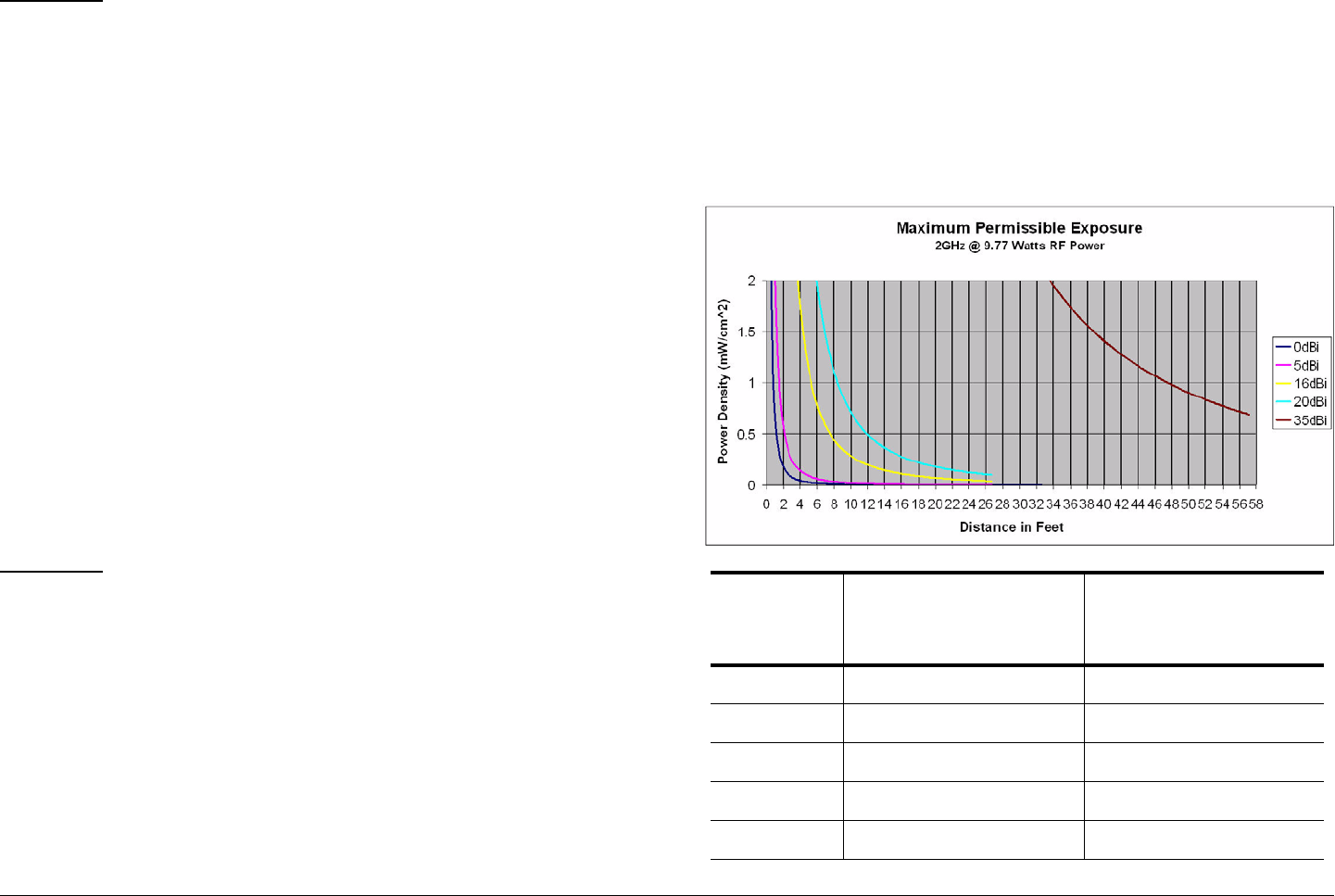
The examples shown in Figure 1 and Figure 2 are typical graphs
for an MRC STRATA Transmitter and show the permissible
exposure distance for various antennas. Graphs and data will
vary, based on the actual transmitter, output power, frequency,
and antenna utilized. One plot provides the permissible output
of the transmitter for digital modulation, and the other plot for
analog modulation.
MRC, in accordance with the requirements set forth by the FCC,
provides this information as a guide to the user. It is assumed
that the users of this equipment are licensed and qualified to
operate the equipment per the guidelines and recommendations
contained within the product user guides and in accordance with
any FCC rules that may apply.
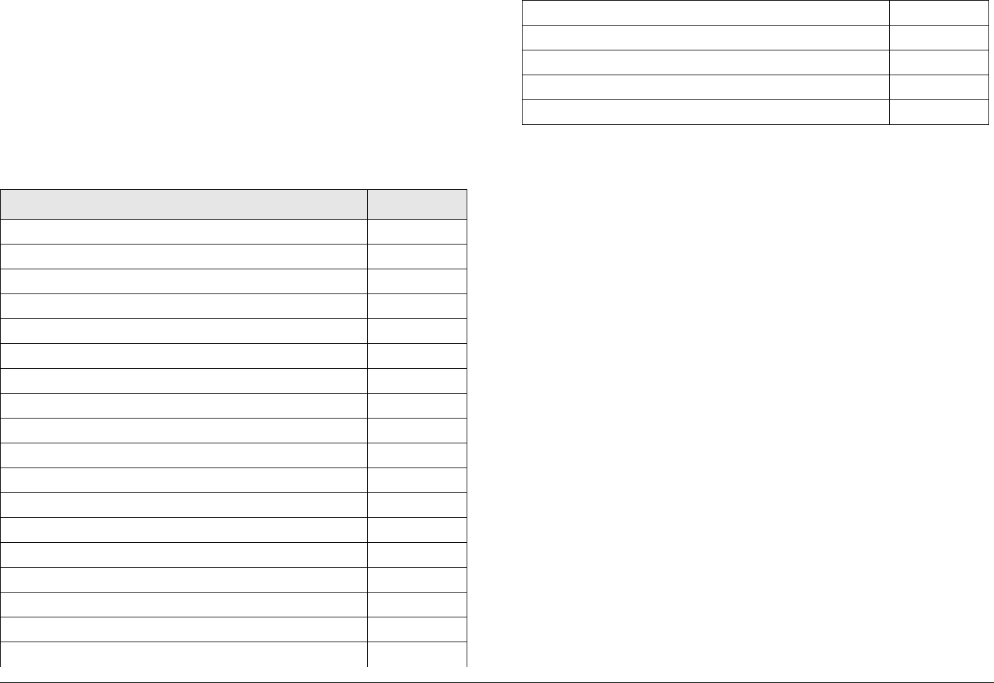
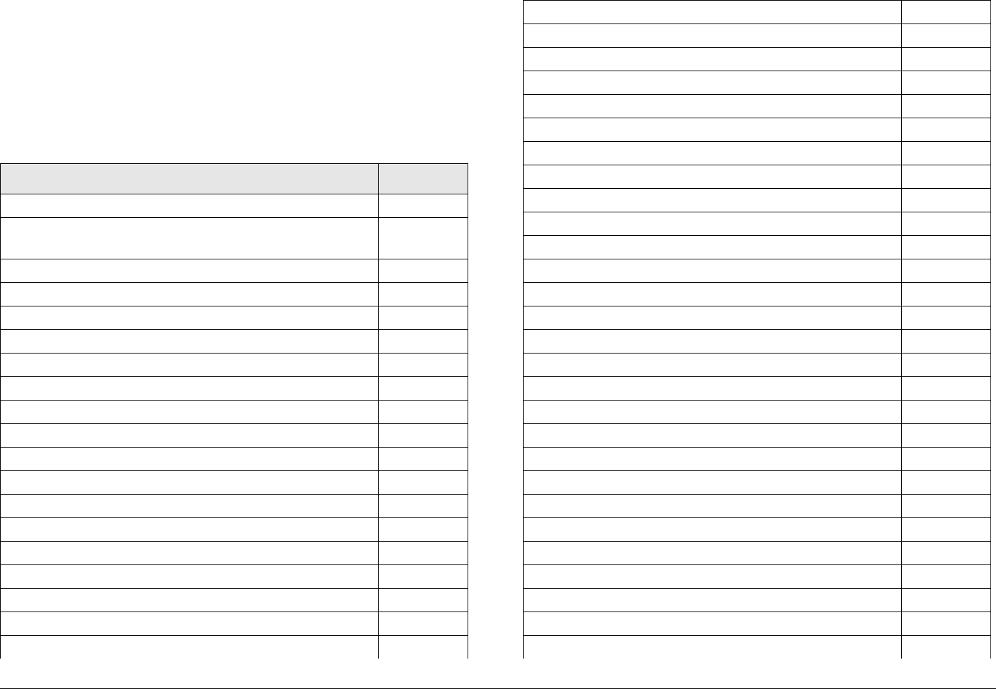
Figure 1 with its corresponding table shows the 2GHz MPE.
Figure 1: MTX5000 MPE 2GHz
Antenna
Gain (dBi)
Minimum Dis-
tance from
Antenna (cm)
Minimum Distance
from Antenna (inch)
028 11.02
550 19.68
16 177 69.67
20 279 109.81
35 1569 617.56
Notices Notices-ivMTX5000 User and Technical Manual
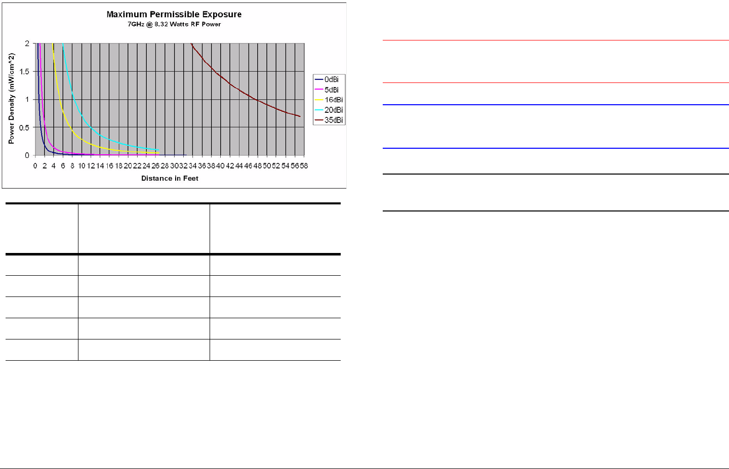
Figure 2 with its corresponding table shows the 7GHz MPE.
Figure 2: MTX5000 MPE 7GHz
Antenna
Gain (dBi)
Minimum Dis-
tance from
Antenna (cm)
Minimum Distance
from Antenna (inch)
026 10.23
546 18.11
16 163 64.16
20 258 101.55
35 1448 569.93
Conventions
Pay special attention to information marked in one of the
following ways:
WARNING Follow WARNINGS closely to prevent
personal injury or death.
CAUTION Follow CAUTIONS to prevent damage to
the equipment.
Note Notes provide additional information to assist you
in using and maintaining the equipment.
Notices Notices-vMTX5000 User and Technical Manual
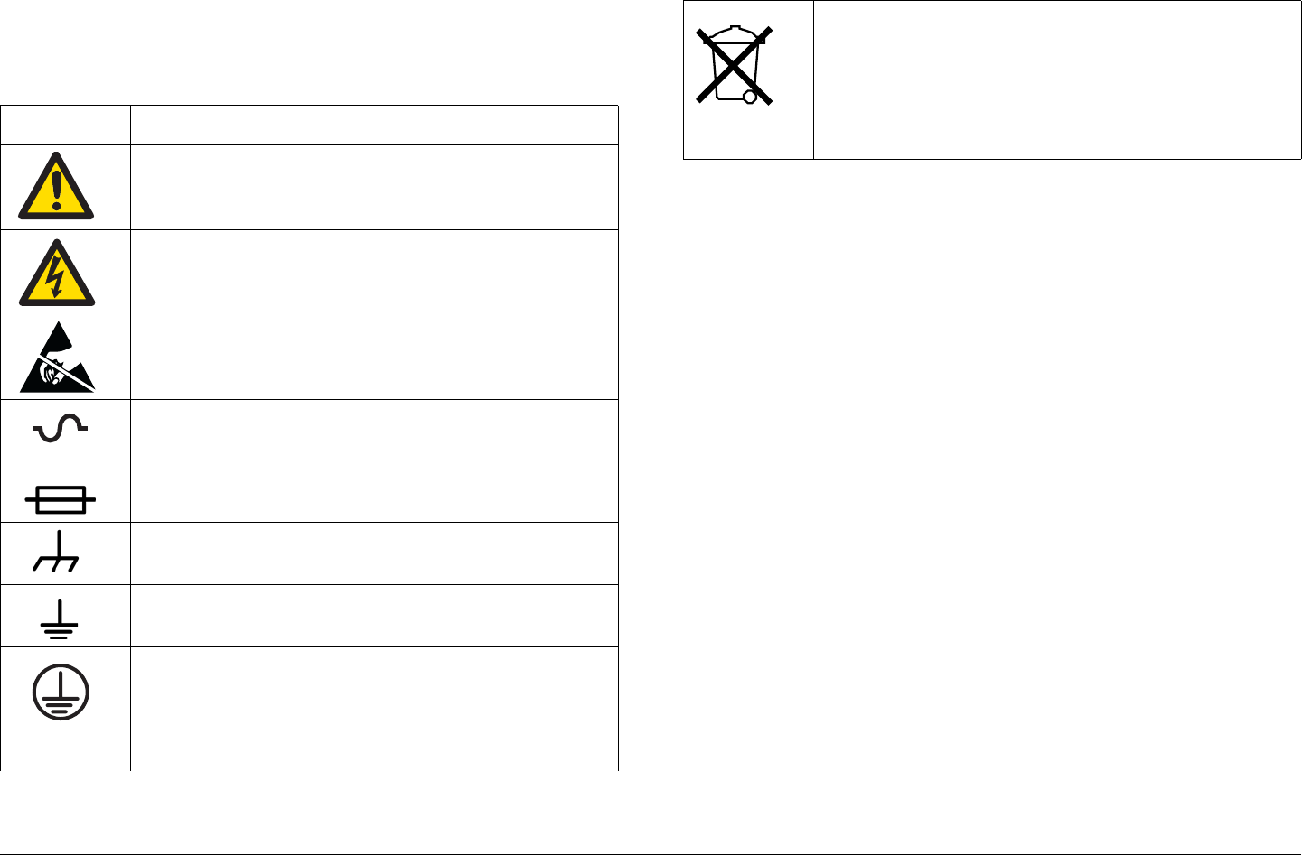
Symbols Used
The following symbols may be used on the equipment or in this
manual:
Symbol Meaning
WARNING: General Warning. Risk of Danger.
WARNING: Risk of Electric Shock.
WARNING: Electrostatic Discharge. Possible
Damage to Equipment.
Fuse - Identifies fuses or their location.
Frame or Chassis Ground - Identifies the frame or
chassis terminal.
Earth Ground - Identifies the earth ground terminal.
Protective Earth Ground - Identifies any terminal
which is intended for connection to an external
conductor for protection against electric shock in
case of a fault, or the terminal on a protective earth
electrode.
OR
Waste Electrical and Electronic Equipment
(WEEE) - The product must not be disposed of
with other waste at the end of its life cycle. It is
the user’s responsibility to dispose of the waste
equipment by handing it over to a designated
collection point for recycling.

Notices Notices-viMTX5000 User and Technical Manual

Contents Contents-1MTX5000 User and Technical Manual
Contents
NOTE TO USER - - - - - - - - - - - - - - - - - - - - - - - - - -i
Overview - - - - - - - - - - - - - - - - - - - - - - - - - - - - - - - - - - - i
Avoid Potential Operational Problems - - - - - - - - - - - - - - - i
Radio Unable to Transmit or Generally Unstable - - - - - i
Improper Power Up/Power Down - - - - - - - - - - - - - - - - i
Radio State Incorrect - - - - - - - - - - - - - - - - - - - - - - - - ii
PA Voltage Adjust Setup Software Hang-up - - - - - - - - ii
RF Levels Too High - - - - - - - - - - - - - - - - - - - - - - - - - iii
Software Recovery - - - - - - - - - - - - - - - - - - - - - - - - - - iii
Color Bar Generator Operations - - - - - - - - - - - - - - - - iii
Using the Color LCD Display Panel Touch Screen- - - iv
Remote Location Operations - - - - - - - - - - - - - - - - - - - v
Ethernet Connections - - - - - - - - - - - - - - - - - - - - - - - - v
Notices - - - - - - - - - - - - - - - - - - - - - - - - - - - - - - - - i
About This Manual - - - - - - - - - - - - - - - - - - - - - - - - - - - - i
Copyright - - - - - - - - - - - - - - - - - - - - - - - - - - - - - - - - - - - i
Proprietary Material - - - - - - - - - - - - - - - - - - - - - - - - - - - - i
Quality Certification - - - - - - - - - - - - - - - - - - - - - - - - - - - - i
General Safety Information- - - - - - - - - - - - - - - - - - - - - - - ii
WARNING - RF Power Hazard - - - - - - - - - - - - - - - - - ii
RF Exposure - Safe Working Distances - - - - - - - - - - - ii
Conventions - - - - - - - - - - - - - - - - - - - - - - - - - - - - - - - - iv
Symbols Used- - - - - - - - - - - - - - - - - - - - - - - - - - - - - - - - v
Contents - - - - - - - - - - - - - - - - - - - - - - - - - - - - - - 1
Introduction- - - - - - - - - - - - - - - - - - - - - - - - - - - 1-1
For Whom It’s Written - - - - - - - - - - - - - - - - - - - - - - - - 1-1
Related Documents - - - - - - - - - - - - - - - - - - - - - - - - - - 1-1
Ordering Documentation - - - - - - - - - - - - - - - - - - - - - - 1-1
Calling for Service - - - - - - - - - - - - - - - - - - - - - - - - - - - 1-1
Tell Us What You Think! - - - - - - - - - - - - - - - - - - - - - - 1-2
Product Description- - - - - - - - - - - - - - - - - - - - - 2-1
Chapter Overview - - - - - - - - - - - - - - - - - - - - - - - - - - - 2-1
Description - - - - - - - - - - - - - - - - - - - - - - - - - - - - - - - - 2-1
General - - - - - - - - - - - - - - - - - - - - - - - - - - - - - - - - 2-1
MPEG Encoding and COFDM Transmission - - - - - - 2-2
Analog Video Encoding and FM Modulation- - - - - - - 2-2
RF Control - - - - - - - - - - - - - - - - - - - - - - - - - - - - - - 2-2
System Components - - - - - - - - - - - - - - - - - - - - - - - - - 2-3
IDU Operating Controls- - - - - - - - - - - - - - - - - - - - - - - - 2-4
External Connectors - - - - - - - - - - - - - - - - - - - - - - - - - - 2-5
Configuration Options- - - - - - - - - - - - - - - - - - - - - - - - - 2-7
IDU Configurations - - - - - - - - - - - - - - - - - - - - - - - - 2-7
AC Power - - - - - - - - - - - - - - - - - - - - - - - - - - - - - - - 2-7
Remote Control Options- - - - - - - - - - - - - - - - - - - - - 2-7
Antenna Options - - - - - - - - - - - - - - - - - - - - - - - - - - 2-8
Band and Frequency Options - - - - - - - - - - - - - - - - - 2-8
System Configurations - - - - - - - - - - - - - - - - - - - - - - - - 2-8
Single-Band/Dual Antenna Transmission- - - - - - - - - 2-9
Dual-Band Non-Simultaneous Transmission - - - - - - 2-9
Dual-Band Simultaneous Transmission - - - - - - - - - 2-10
Operating System Modes - - - - - - - - - - - - - - - - - - - - - 2-11
General - - - - - - - - - - - - - - - - - - - - - - - - - - - - - - - 2-11
Normal User Mode - - - - - - - - - - - - - - - - - - - - - - - 2-11
System Setup Mode - - - - - - - - - - - - - - - - - - - - - - 2-11
For More Information - - - - - - - - - - - - - - - - - - - - - - - - 2-11
Routine Operation - - - - - - - - - - - - - - - - - - - - - 3-1
Chapter Overview - - - - - - - - - - - - - - - - - - - - - - - - - - - 3-1
Overview of Controls, Indicators, and Connectors - - - - - 3-2
MTX5000 IDU Controls, Indicators, and Connectors- 3-2
MTX5000 ODU Connectors - - - - - - - - - - - - - - - - - 3-6
Preparing for Operation - - - - - - - - - - - - - - - - - - - - - - - 3-7
Mobile Installation - - - - - - - - - - - - - - - - - - - - - - - - - 3-7
Powering the MTX5000 System - - - - - - - - - - - - - - - 3-7
Using the MTX5000 Screens in Local Mode - - - - - - - - 3-10
Overview - - - - - - - - - - - - - - - - - - - - - - - - - - - - - - 3-10

Contents Contents-2MTX5000 User and Technical Manual
Main Screen - - - - - - - - - - - - - - - - - - - - - - - - - - - 3-11
Color LCD Display Panel- - - - - - - - - - - - - - - - - - - 3-13
Touch Screen and Function Keys - - - - - - - - - - - - 3-13
Navigation Between Main and Status Screens - - - 3-14
Transmitter Operation Buttons - - - - - - - - - - - - - - - 3-14
Local/Remote Control Status Button- - - - - - - - - - - 3-16
Setup Screen Options - - - - - - - - - - - - - - - - - - - - 3-16
Radio Screen Options- - - - - - - - - - - - - - - - - - - - - 3-17
Select Local/Remote Operation Mode - - - - - - - - - - - 3-20
MTX5000 Local Operations - - - - - - - - - - - - - - - - - - - 3-23
Select Preset - - - - - - - - - - - - - - - - - - - - - - - - - - 3-24
Select RF Band - - - - - - - - - - - - - - - - - - - - - - - - 3-27
Select/Customize Operating Channels - - - - - - - - 3-30
Select Channel Offset - - - - - - - - - - - - - - - - - - - - 3-32
Select Antenna - - - - - - - - - - - - - - - - - - - - - - - - - 3-33
Select Antenna Polarization - - - - - - - - - - - - - - - - 3-34
Enable/Disable Transmitter - - - - - - - - - - - - - - - - 3-35
Select High/Low Power Mode - - - - - - - - - - - - - - 3-36
Monitor ODU Status - - - - - - - - - - - - - - - - - - - - - 3-36
Monitor IDU Status - - - - - - - - - - - - - - - - - - - - - - 3-37
Monitor SUM Errors - - - - - - - - - - - - - - - - - - - - - 3-38
Monitor Current Preset Status Settings- - - - - - - - - 3-38
Perform PA Voltage Adjust Setup - - - - - - - - - - - - 3-44
Perform RF Level Adjust - - - - - - - - - - - - - - - - - - - 3-49
Select Color Bar Generator Mode - - - - - - - - - - - - 3-52
Set Time and Date - - - - - - - - - - - - - - - - - - - - - - - 3-54
Perform IDU Diagnostics- - - - - - - - - - - - - - - - - - - 3-56
Review System Information - - - - - - - - - - - - - - - - - 3-57
Set Last PA State - - - - - - - - - - - - - - - - - - - - - - - - 3-58
Using the MTX5000 in Remote Mode - - - - - - - - - - - - 3-60
Overview - - - - - - - - - - - - - - - - - - - - - - - - - - - - - - 3-60
Remote Screen Display - - - - - - - - - - - - - - - - - - - 3-61
Remote Configuration Setting Selections - - - - - - - 3-64
Transmitter Controls - - - - - - - - - - - - - - - - - - - - - 3-66
Alerts - - - - - - - - - - - - - - - - - - - - - - - - - - - - - - - - - 3-66
Remote Location Operations- - - - - - - - - - - - - - - - - - - 3-67
Select Preset - - - - - - - - - - - - - - - - - - - - - - - - - - - 3-67
Select RF Band and Channel Plan - - - - - - - - - - - - 3-68
Select Operating Channel - - - - - - - - - - - - - - - - - - 3-69
Select Antenna - - - - - - - - - - - - - - - - - - - - - - - - - - 3-70
Select Frequency Offset - - - - - - - - - - - - - - - - - - - 3-70
Select Antenna Polarization - - - - - - - - - - - - - - - - 3-70
Enable/Disable Transmitter - - - - - - - - - - - - - - - - - 3-71
Select High/Low RF Power Mode - - - - - - - - - - - - - 3-71
Monitor Alerts - - - - - - - - - - - - - - - - - - - - - - - - - - - 3-72
Routine vs. Advanced Operation Configuration Settings 3-73
Troubleshooting - - - - - - - - - - - - - - - - - - - - - - - 4-1
Chapter Overview - - - - - - - - - - - - - - - - - - - - - - - - - - - 4-1
Error Messages - - - - - - - - - - - - - - - - - - - - - - - - - - - - - 4-1
Ethernet Connections- - - - - - - - - - - - - - - - - - - - - - - - - 4-4
Advanced Operations - - - - - - - - - - - - - - - - - - - 5-1
Chapter Overview - - - - - - - - - - - - - - - - - - - - - - - - - - - 5-1
Before You Begin- - - - - - - - - - - - - - - - - - - - - - - - - - - - 5-1
MTX5000 - - - - - - - - - - - - - - - - - - - - - - - - - - - - - - - 5-2
Software - - - - - - - - - - - - - - - - - - - - - - - - - - - - - - - 5-2
Settings - - - - - - - - - - - - - - - - - - - - - - - - - - - - - - - - 5-2
System Rules - - - - - - - - - - - - - - - - - - - - - - - - - - - - 5-2
Configuration Settings - - - - - - - - - - - - - - - - - - - - - - 5-3
Local Mode Password Control - - - - - - - - - - - - - - - - - - 5-3
Create or Update Preset Configuration Settings in Local Mode
5-6 Create or Update Custom Analog Preset Configuration In
Local Mode - - - - - - - - - - - - - - - - - - - - - - - - - - - - - - - - - - 5-7
Create or Update Digital COFDM Preset Configuration Set-
tings in Local Mode - - - - - - - - - - - - - - - - - - - - - - - - - - - 5-17
Create or Update Digital ASI Preset Configuration Settings
in Local Mode- - - - - - - - - - - - - - - - - - - - - - - - - - - - - - - - 5-30

Contents Contents-3MTX5000 User and Technical Manual
Create or Update Digital LMS-T Preset Configuration Set-
tings in Local Mode - - - - - - - - - - - - - - - - - - - - - - - - - - - 5-34
Create or Update Digital DVB-S Preset Configuration Set-
tings in Local Mode - - - - - - - - - - - - - - - - - - - - - - - - - - - 5-47
Create or Update Digital IP Preset Configuration Settings
in Local Mode - - - - - - - - - - - - - - - - - - - - - - - - - - - - - - 5-60
Create or Update Preset Configuration Settings in Remote
Mode - - - - - - - - - - - - - - - - - - - - - - - - - - - - - - - - - - - - - 5-73
Create or Update Custom Analog Preset Configuration in
Remote Mode - - - - - - - - - - - - - - - - - - - - - - - - - - - - - - 5-73
Create or Update Custom Digital COFDM Preset Configu-
ration in Remote Mode - - - - - - - - - - - - - - - - - - - - - - - - 5-77
Create or Update Custom Digital ASI Preset Configuration
in Remote Mode - - - - - - - - - - - - - - - - - - - - - - - - - - - - 5-82
Create or Update Custom Digital LMS-T Preset Configura-
tion in Remote Mode - - - - - - - - - - - - - - - - - - - - - - - - - - 5-86
Create or Update Custom Digital DVB-S Preset Configura-
tion in Remote Mode - - - - - - - - - - - - - - - - - - - - - - - - - - 5-91
Create or Update Custom Digital IP Preset Configuration
in Remote Mode - - - - - - - - - - - - - - - - - - - - - - - - - - - - - 5-96
Preset File Management - - - - - - - - - - - - - - - - - - - - 5-101
Restore Presets to Defaults- - - - - - - - - - - - - - - - 5-102
Save Preset Configurations to a File - - - - - - - - - 5-104
Load Preset Configurations from a File- - - - - - - - 5-106
Set Network Addresses for Remote Operation - - - - 5-109
Firmware Update - - - - - - - - - - - - - - - - - - - - - - - - - 5-114
License Manager- - - - - - - - - - - - - - - - - - - - - - - - - - 5-117
Installation - - - - - - - - - - - - - - - - - - - - - - - - - - - 6-1
Chapter Overview - - - - - - - - - - - - - - - - - - - - - - - - - - - 6-1
Unpacking - - - - - - - - - - - - - - - - - - - - - - - - - - - - - - - - 6-1
Initial Inspection - - - - - - - - - - - - - - - - - - - - - - - - - - - - 6-2
Damage in Shipment - - - - - - - - - - - - - - - - - - - - - - - - - 6-2
Installing the MTX5000 IDU - - - - - - - - - - - - - - - - - - - 6-2
Site Preparation - - - - - - - - - - - - - - - - - - - - - - - - - - 6-2
Mounting the MTX5000 IDU - - - - - - - - - - - - - - - - - - 6-3
Power Connections - - - - - - - - - - - - - - - - - - - - - - - - - - 6-4
Power Requirements - - - - - - - - - - - - - - - - - - - - - - - 6-4
Power Supply and Distribution - - - - - - - - - - - - - - - - 6-4
Grounding - - - - - - - - - - - - - - - - - - - - - - - - - - - - - - - - - 6-5
Defining the Wiring Harness - - - - - - - - - - - - - - - - - - - - 6-5
Steps to Define the Harness- - - - - - - - - - - - - - - - - - 6-5
Select the Type of RF/Power Cabling - - - - - - - - - - - 6-5
Select the Function Cables Required - - - - - - - - - - - 6-7
Determine the Size of Harness Required- - - - - - - - - 6-9
Cabling Requirements - - - - - - - - - - - - - - - - - - - - - - - - 6-9
MTX5000 System Type “N” Connector Interface - - 6-11
MTX5000 System TNC Connector Interface - - - - - 6-12
Installing the Fabricated Harness- - - - - - - - - - - - - - - - 6-13
Installing the Outdoor Unit - - - - - - - - - - - - - - - - - - - - 6-13
Site Preparation - - - - - - - - - - - - - - - - - - - - - - - - - 6-14
Mounting the ODU - - - - - - - - - - - - - - - - - - - - - - - 6-14
Making the Connections - - - - - - - - - - - - - - - - - - - - - - 6-15
Mast Top Connections- - - - - - - - - - - - - - - - - - - - - 6-16
IDU Connections- - - - - - - - - - - - - - - - - - - - - - - - - 6-16
Wayside Data Connections - - - - - - - - - - - - - - - - - - - - 6-24
Wayside Connections - - - - - - - - - - - - - - - - - - - - - 6-24
Compatibility- - - - - - - - - - - - - - - - - - - - - - - - - - - - 6-24
Audio Connections - - - - - - - - - - - - - - - - - - - - - - - - - - 6-24
Audio Inputs - - - - - - - - - - - - - - - - - - - - - - - - - - - - 6-24
Analog Audio Inputs - - - - - - - - - - - - - - - - - - - - - - 6-25
Digital Audio Inputs - - - - - - - - - - - - - - - - - - - - - - - 6-25
ODU Power - - - - - - - - - - - - - - - - - - - - - - - - - - - - - - 6-26
Remote Control Operations- - - - - - - - - - - - - - - - - - - - 6-26
Powering Up - - - - - - - - - - - - - - - - - - - - - - - - - - - - - - 6-27
Checks Before Power-Up- - - - - - - - - - - - - - - - - - - 6-27
Initial Power-Up - - - - - - - - - - - - - - - - - - - - - - - - - 6-27
Power Down - - - - - - - - - - - - - - - - - - - - - - - - - - - 6-29
Product Modifications - - - - - - - - - - - - - - - - - - - - - - - - 6-29

Contents Contents-4MTX5000 User and Technical Manual
Replacement Parts and Supported Repairs - - - 7-1
Chapter Overview - - - - - - - - - - - - - - - - - - - - - - - - - - - 7-1
External Cables and Adapters - - - - - - - - - - - - - - - - - - 7-1
AC Power Fuses - - - - - - - - - - - - - - - - - - - - - - - - - - - - 7-1
Supported Repairs - - - - - - - - - - - - - - - - - - - - - - - - - - 7-1
Theory of Operation- - - - - - - - - - - - - - - - - - - - - 8-1
Chapter Overview - - - - - - - - - - - - - - - - - - - - - - - - - - - 8-1
System Architecture - - - - - - - - - - - - - - - - - - - - - - - - - 8-1
General - - - - - - - - - - - - - - - - - - - - - - - - - - - - - - - - 8-1
Architecture - - - - - - - - - - - - - - - - - - - - - - - - - - - - - 8-1
MPEG Encoding and COFDM Transmission - - - - - - 8-2
Analog Video Encoding and FM Modulation - - - - - - 8-2
MTX5000 User Interface - - - - - - - - - - - - - - - - - - - - 8-2
ODU RF Output - - - - - - - - - - - - - - - - - - - - - - - - - - 8-3
MTX5000 Internal Software - - - - - - - - - - - - - - - - - - 8-3
Outdoor Unit Details - - - - - - - - - - - - - - - - - - - - - - - - 8-5
Installing Triax Connectors - - - - - - - - - - - - - - - A-1
Appendix Overview - - - - - - - - - - - - - - - - - - - - - - - - - - A-1
Sealing- - - - - - - - - - - - - - - - - - - - - - - - - - - - - - - - - - - A-1
Analog Color Bar Generator- - - - - - - - - - - - - - - B-1
Appendix Overview - - - - - - - - - - - - - - - - - - - - - - - - - - B-1
Description - - - - - - - - - - - - - - - - - - - - - - - - - - - - - - - - B-1
Functions - - - - - - - - - - - - - - - - - - - - - - - - - - - - - - - B-1
Operating Modes- - - - - - - - - - - - - - - - - - - - - - - - - - B-1
Configuration - - - - - - - - - - - - - - - - - - - - - - - - - - - B-2
Technical Background - - - - - - - - - - - - - - - - - - - - - - B-2
Configuration - - - - - - - - - - - - - - - - - - - - - - - - - - - - - - - B-2
General - - - - - - - - - - - - - - - - - - - - - - - - - - - - - - - B-2
Entering Characters- - - - - - - - - - - - - - - - - - - - - - - - B-4
Preliminary Setup Procedure - - - - - - - - - - - - - - - - - B-4
Configure Text Line A - - - - - - - - - - - - - - - - - - - - - - B-8
Configure Text Line B - - - - - - - - - - - - - - - - - - - - - - B-9
Configure Control Line - - - - - - - - - - - - - - - - - - - - - B-10
Check the Configuration- - - - - - - - - - - - - - - - - - - - B-13
Configuration Reference - - - - - - - - - - - - - - - - - - - - - - B-16
Button Functions - - - - - - - - - - - - - - - - - - - - - - - - - B-16
Full Character Set - - - - - - - - - - - - - - - - - - - - - - - - B-17
Character Subsets- - - - - - - - - - - - - - - - - - - - - - - - B-18
Delay Values - - - - - - - - - - - - - - - - - - - - - - - - - - - B-18
Index - - - - - - - - - - - - - - - - - - - - - - - - - - - - - - - - - - 1

1
Introduction 1-1MTX5000 User and Technical Manual
Introduction
1.1 For Whom It’s Written
This manual is intended for use by qualified operators, installers,
and service personnel. Users of this manual should already be
familiar with the basic concepts of radio, video, and audio.
1.2 Related Documents
• MTX5000 Preset Settings (part no. 400558-1)
• Glossary of Terms and Abbreviations (part no. 400576-1)
• Channels and Frequencies Technical Information (part no.
400580-1)
1.3 Ordering Documentation
Any of the above manuals may be ordered by contacting MRC
Customer Service:
Business Hours: Monday - Friday
8:00 AM - 5:00 PM Eastern Time (US)
(0800 - 1700 hrs US ET)
Telephone: 800.490.5700 (Press 3)
+1.978.671.5700 (Press 3)
E-mail: customerservice@mrcbroadcast.com
When contacting Customer Service, please have the following
information available:
• Model number and serial number of the unit. This is
located on a label on the right-hand side of each unit.
• Approximate purchase date.
1.4 Calling for Service
MRC Technical Support is available 24 hours a day, 7 days a
week. During regular business hours you can reach our expert
staff directly.
Business Hours: Monday - Friday
8:00 AM - 5:00PM Eastern Time (US)
(0800 - 1700 hrs US ET)
Telephone: 888.777.9221 (US and Canada)
+1.978.671.5929
E-mail: technicalsupport@mrcbroadcast.com
After regular business hours and on weekends and holidays, you
can also reach our expert staff as follows:
Telephone: 888.777.9221 (US and Canada)
+1.978.671.5929
Your call will be automatically forwarded to the on-call Technical
Support specialist.
When contacting Technical Support, please have the following
information available:
• Model number and serial number of the unit. This is
located on a label on the right-hand side of each unit.
• Approximate purchase date.

Introduction 1-2MTX5000 User and Technical Manual
1.5 Tell Us What You Think!
We’d appreciate any comments or suggestions you have about
this manual. The more feedback we get, the better the manuals
get!
If you’re viewing this manual electronically, it’s easy - just click on
the link below to send us an E-mail.
Or, you can E-mail our Technical Support team at:
technicalsupport@mrcbroadcast.com
Be sure to tell us what product you’re writing about, and which
manual.
Feedback
2
Product Description 2-1MTX5000 User and Technical Manual
Product Description
2.1 Chapter Overview
This chapter provides an overall description of the MTX5000
Transmitter System (MTX5000), its components, and its
capabilities.
Here are the topics covered:
Topic Page
Description 2-1
General 2-1
MPEG Encoding and COFDM Transmission 2-2
Analog Video Encoding and FM Modulation 2-2
RF Control 2-2
System Components 2-3
IDU Operating Controls 2-4
External Connectors 2-5
Configuration Options 2-7
IDU Configurations 2-7
AC Power 2-7
Remote Control Options 2-7
Antenna Options 2-8
Band and Frequency Options 2-8
System Configurations 2-8
Single-Band/Dual Antenna Transmission 2-9
Dual-Band Non-Simultaneous Transmission 2-9
Dual-Band Simultaneous Transmission 2-10
2.2 Description
2.2.1 General
The MTX5000 is a highly reliable, flexible, and compact video
microwave transmitter system with modulation and encoding
functions. The MTX5000 system includes an Indoor Unit (IDU)
consisting of the 19-inch wide, 2-rack unit (2RU) high, rack-
mounted transmitter and a mast-mounted Outdoor Unit (ODU),
also called an RF Unit (RFU) or an RF head.
For dual band MTX5000 Transmitter System configurations, the
system will contain both a 2 GHz and a 7 GHz ODU. All
configurations of the MTX5000 IDU provide a 70 MHz IF output
and control to the 2 GHz and/or 7 GHz ODU.
The MTX5000 is a rack-mounted, RF High Definition (HD)-ready
video transmission system with both analog and digital
modulation capabilities. The MTX5000 provides a sophisticated
user interface with an intuitive keypad scheme and an adjustable
color LCD display panel with touch screen control.
A fully equipped MTX5000 package is HD-ready and provides a
robust HD link from the field to the studio. Several digital video
input formats are accepted, as well as analog composite for both
COFDM (DVB-T) and analog FM transmission. In addition, the
MTX5000 can accept several analog audio inputs for FM analog
transmission.
Operating System Modes 2-11
General 2-11
Normal User Mode 2-11
System Setup Mode 2-11
For More Information 2-11

Product Description 2-2MTX5000 User and Technical Manual
The MTX5000 has two mast-mounted ODU bands available.
Consult your Sales Representative or contact the factory for the
latest bands available. These ODUs contain integrated RF up-
conversion circuitry and high power RF amplifiers for maximum
power and signal quality.
With the new demands for digital modulation, the ODUs have
been optimized for improved Modulation Error Ratio/Error Vector
Magnitude (MER/EVM) performance with COFDM transmission.
2.2.2 MPEG Encoding and COFDM Transmission
The MTX5000 is capable of encoding both Standard Definition
(SD) and HD video, depending upon the options contained in
your MTX5000 system. Available inputs include SD Serialized
Digital video (ASI-SDI), HD-SDI, and composite video.
Audio input formats currently include digital AES/EBU and
analog formats. Future enhancements will include AC-3
SMPTE-302. The encoder is also capable of encoding an RS-
232 signal as Wayside data. The MTX5000 is capable of
generating a fully compliant DVB-T compliant output signal. This
provides a robust digital link in any hostile transmission
environment.
2.2.3 Analog Video Encoding and FM Modulation
When in the analog FM mode, the MTX5000 will accept a
standard composite video input. It will also accept analog audio
inputs. The FM analog signal is useful when working with older
legacy equipment or when an analog transmission is desired.
The MTX5000 IDU communicates with the ODU to set operating
frequencies and power levels. This interface is also used for
calibration of the ODU power supply and to monitor error
conditions.
2.2.4 RF Control
The MTX5000 IDU (Figure 2-1) is designed to accept a variety of
external video and audio signals in different digital format
streams and analog signals and to provide a modulated 70 MHz
IF output.
Figure 2-1: MTX5000 Indoor Unit
The MTX5000 IDU allows you to switch between analog and
digital modes where both applications are used. The MTX5000
also provides separate video and audio or baseband composite
operations.
Key features of the MTX5000 IDU are as follows:
• Switchable Analog or Digital modes
• SD/HD SDI interfaces with multiplexing
• Integrated SD/HD MPEG-2/H.264 encoding technologies
• FM transmitter modulation technology (analog)
• DVB-T COFDM modulation technology (digital)
• IF (70 MHz) signal input and monitoring
• Video monitoring output
• Video and audio inputs for NTSC or PAL video/audio
signal transmission
Product Description 2-3MTX5000 User and Technical Manual
• Front panel keypad and touch screen display for
operation and control
• Multiple configuration options available
• Built-in digital Color Bar Generator
• Optional analog Color Bar Generator is available.
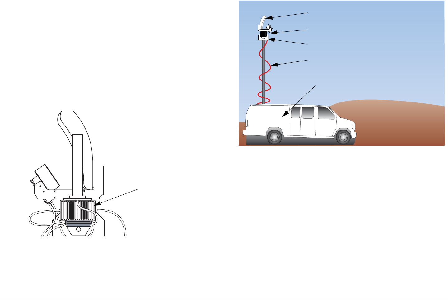
The MRC ODU (See Figure 2-2) performs the signal up-
conversion from 70 MHz IF to RF (2 GHz or 7 GHz) and provides
signal amplification, as required. For dual band operation, two
separate ODUs are required, one for 2 GHz operation, and one
for 7 GHz operation.
Figure 2-2: Outdoor Unit - Typical
A typical installation is shown in Figure 2-3. The MTX5000 IDU
is typically mounted in a standard 19-inch (48.3 cm) rack for
mobile installations. The ODU is mounted on an antenna mast.
Outdoor Unit -
Typical Installation
Figure 2-3: Typical MTX5000 Transmitter System
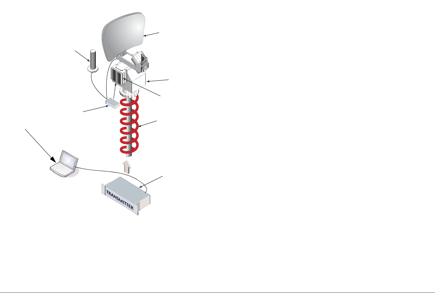
2.3 System Components
The MTX5000 system consists of the IDU and the ODU(s). A
typical system is shown in Figure 2-4 on page 2-4. The IDU
contains the baseband circuitry, power supply, and control
modules. It accepts a wide variety of audio and video inputs,
both analog and digital, and generates a 70 MHz IF output. The
IDU also accepts IF inputs from external modulators.
The IDU can be controlled locally from the front panel controls or
it can be controlled remotely. The IDU can be controlled from a
PC at a remote location, such as a studio, via the PC web
browser. The optional Remote Access Subnotebook PC can
also be used to provide remote control of the IDU during mobile
operations.
Antenna
Pan & Tilt Assembly
Outdoor Unit (ODU)
Conduit (Nycoil)
Indoor Unit (IDU)
(Inside Vehicle)
Product Description 2-4MTX5000 User and Technical Manual
Figure 2-4: MTX5000 System Components - Typical
For digital operation, the IDU is equipped with an internal MPEG/
COFDM module.
The ODU contains the upconverters and the power amplifier.
The ODU accepts the 70 MHz IF output from the IDU, converts
RF Switch
Directional Antenna
(MRC 2A20, 7A30,
Ellipse 2000, etc.)
Pan & Tilt Asse
m
Outdoor RF Unit
(Upconvertor,
Power Amp)
Conduit (Nycoil)
OmniPole
Antenna
MTX5000 Indoor Un
i
(Baseband, Audio/Vi
d
Modules)
Laptop PC,
Remote Access
Subnotebook PC,
or PC
the IF to the RF operating band required, and amplifies the RF
output, as required.
All installations will include an antenna, either directional,
omnidirectional, or both. An MRC RF switch can be mounted on
the antenna mast to select the antenna required.
When using the mast-mounted antenna(s), a Nycoil conduit
sheath covers the wiring harness between the IDU and the ODU.
The wiring harness carries the DC power, 70 MHz IF, and
antenna band and polarization switching control. Additional
wiring is contained in the Nycoil conduit sheath for controlling the
antenna pan and tilt mechanism and for implementing additional
functions such as off-air monitors, mast lights, etc.
2.4 IDU Operating Controls
All controls are located on the front panel of the MTX5000 IDU.
There are no controls on the ODU.
All transmitter functions are controlled using the color LCD
display panel touch screen and/or function keys, as shown in
Figure 2-5 on page 2-5.
The color LCD display panel with touch screen and function keys
are used to select control and diagnostic menu screens for both
the IDU and the ODU. Option buttons displayed on the color
LCD display panel are used to control Preset selection, RF band
selection, channel selection, offset selection, antenna selection,
antenna polarization, transmitter operation (on or off), power
(low or high), and to monitor the status of the IDU and ODU.
The option buttons displayed on the color LCD display panel
may be selected using either the color LCD display panel touch
screen or the function keys.
Product Description 2-5MTX5000 User and Technical Manual Product Description 2-5MTX5000 User and Technical Manual
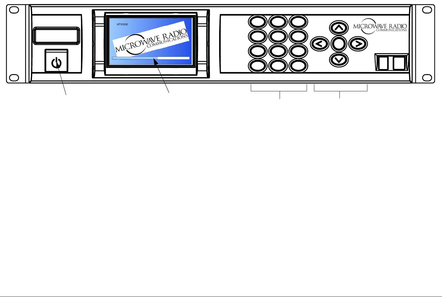
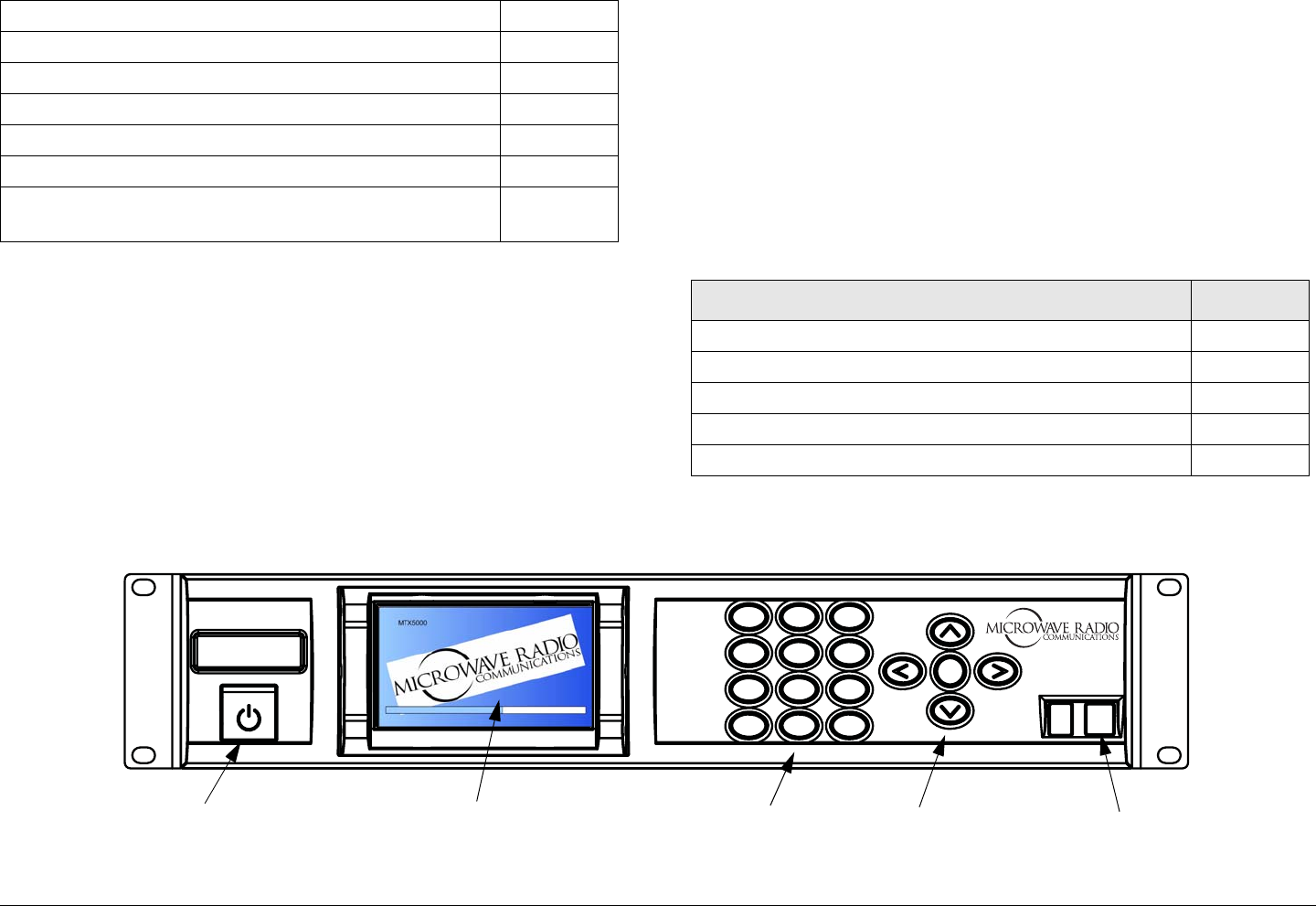
Figure 2-5: MTX5000 Front Panel View
1
4 GHI
7 PQRS
*Shift
2 ABC
5 JKL
8 TUV
0
3 DEF
6 MNO
9WXYZ
SEL
#Space
MTX5000
Power Switch Color LCD Display
Panel with Touch
Screen
Keypad (Not
Currently
Operational)
Function Keys
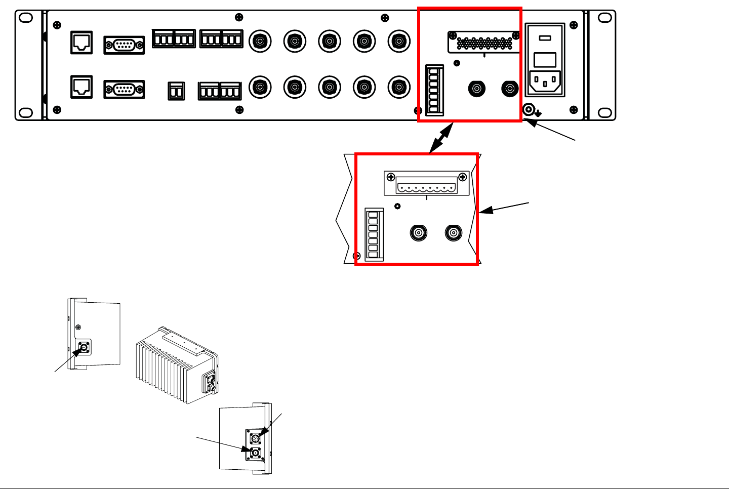
2.5 External Connectors
The rear panels of the MTX5000 IDU configurations contain the
I/O connectors and an input fuse, as shown in Figure 2-6 on
page 2-6. Connectors contained on the ODU are shown in
Figure 2-7 on page 2-6.
The MTX5000 system is designed to make upgrading from an
older radio as easy as possible. The IDU and ODU can be
ordered with a variety of connectors to plug into an existing
wiring harness. Connectors available for the cable connection
between the IDU and ODU are as follows:
• Triax (both ends)
• Type “N” (both ends)
• TNC (both ends).
If your MTX5000 system contains the TNC connector option on
the IDU, a TNC connector must be attached to the ODU end of
the cable for weather and reliability purposes.
All ODU configurations contain a standard Type “N” connector
for connection to the antenna.
If your MTX5000 system IDU is equipped with either Type “N” or
TNC connectors, the IDU will contain an 8-pin Weidmuller
connector to provide DC power and control to the ODU via the
ODU POWER connector.
If your system is equipped with Triax connectors, the 8-pin
Weidmuller connector will not be present on the rear panel of
the IDU. With the Triax connector option, both DC power and
control are provided to the ODU via the Triax cable connected
between the IDU and the ODU. If the Triax connector option is
contained on your MTX5000 system, a POWER connector will
not be present on the ODU.
For additional information, refer to the “ Installation” Chapter on
page 6-1.
Product Description 2-6MTX5000 User and Technical Manual Product Description 2-6MTX5000 User and Technical Manual
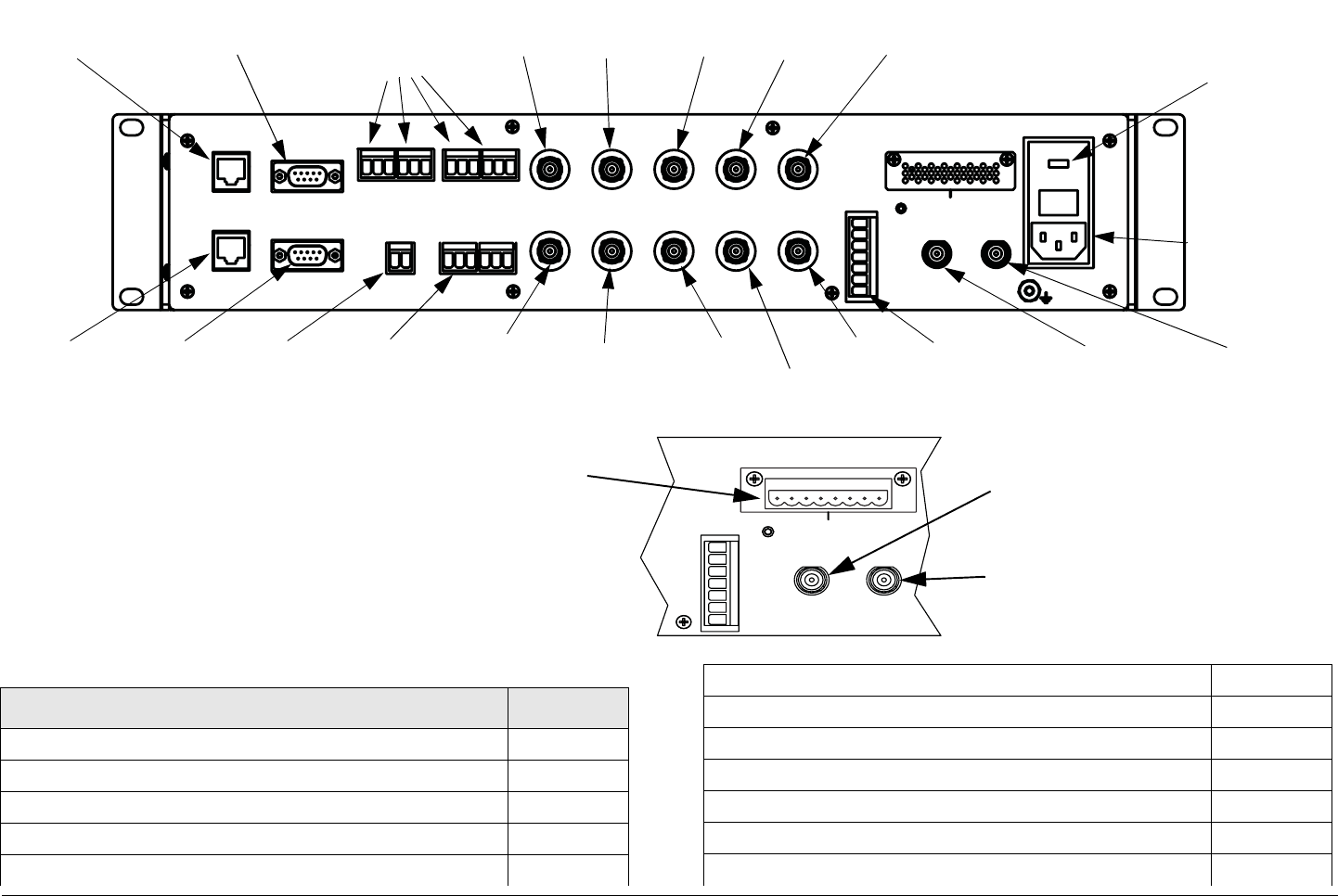
Figure 2-6: MTX5000 IDU Rear Panel Configurations
ETHERNET
RTN DATA
WAYSIDE
ATPC
AUDIO
1234
+ G - + G - + G - + G -
SUM
ALARM
AES/EBU VIDEO IN
BB IN IF MON
AC-3
SMPTE 302
ASI 1 HD-SDI ASI 2
IF IN VID MON SDI/ASI
ANT
CONTROL
RFU POWER OUT
RFU 1 RFU 2
H
V
LCP
ANT2
BAND2
GND
+
- - + +
- - + +
12
POWER IN
+ G - + G -
12
ANT
CONTROL
RFU POWER OUT
RFU 1 RFU 2
H
V
LCP
ANT2
BAND2
GND
+
- - + +
- - + +
12
MTX5000 IDU
Configuration with Triax
Connectors
MTX5000 IDU
Configuration with Type
“N” or TNC Connectors
Figure 2-7: MTX5000 ODU Connectors
RF OUT
RF IN
IDU
RF OUT
Connector
POWER
Connector
(With TNC
and Type
“N” RF IN
Connector
Options
Only)
RF IN
Connector
The IDU connects to the ODU through the wiring harness
between the units. The wiring harness contains DC power, 70
MHz IF, and control for all components mounted on the top of
the antenna mast. Functions and control contained in the wiring
harness typically include the following:
• 70 MHz IF, control, and alarms between the IDU and the
ODU
• DC power to the ODU
• Power and control for an RF switch to select antennas
• Power and control for antenna switching functions (band,
polarization, and power)

Product Description 2-7MTX5000 User and Technical Manual
• Power for mast top lights
• Control and power for the Pan and Tilt assembly
• RF and control for an off-air antenna
• Mast top safety sensors for proximity, high voltage, etc.
Since each installation may be different, the harness must be
specified for each installation. The harness can be supplied by
MRC, or it is often supplied by the van integrator.
2.6 Configuration Options
MRC is constantly working to expand and upgrade the
capabilities of the MTX5000. Consult your Sales Representative
or contact the factory for the latest information.
2.6.1 IDU Configurations
Your MTX5000 IDU consists of an MPEG encoder, a COFDM
modulator, and an analog FMT module.
2.6.2 AC Power
The MTX5000 IDU operates on the following AC power:
• 120/240 VAC, 50/60 Hz
Fuse ratings for the AC power sources are listed in Table 2-1.
Table 2-1: AC Fuse Ratings
Operating Voltage Fuse Rating
120 VAC, 50/60 Hz 3.0A SB 250V 3AG or 5 x 20 mm
240 VAC, 50/60 Hz 1.5A SB 250V 3AG or 5 x 20 mm
AC power is applied to the MTX5000 IDU, which in turn, provides
DC power to the ODU via the wiring harness between them.
Refer to the “ Installation” Chapter on page 6-1 for additional
information.
2.6.3 Remote Control Options
For portable mobile operations, the MTX5000 system may be
controlled using either a Windows-based laptop PC or by the
optional Windows-based Remote Access Subnotebook PC. See
Figure 2-8.
Figure 2-8: Remote Access Subnotebook PC
Using either PC eliminates the need for a separate panel-
mounted remote control panel to control the MTX5000 system.

Product Description 2-8MTX5000 User and Technical Manual
An RJ-45 crossover cable is required for connection to
either PC for mobile remote control operations.
The MTX5000 system may also be controlled from a Windows-
based PC at a remote location. When controlling the MTX5000
system from a remote location, the remote PC is connected to
the MTX5000 system via the Ethernet.
To connect Windows-based PCs to the MTX5000 system, see
”Select Local/Remote Operation Mode” on page 3-20. To
connect the optional Windows-based Remote Access
Subnotebook PC to the MTX5000 system, refer to the Remote
Access Subnotebook PC Operator’s Guide, part number
400573-1, provided with the optional Remote Access
Subnotebook PC.
Information and procedures required to control the MTX5000
system for either portable mobile applications or for remote
location operations are provided in “Using the MTX5000 in
Remote Mode” on page 3-60 and “Remote Location Operations”
on page 3-67. Procedures required to control the MTX5000
system using either a Windows-based laptop PC, the optional
Windows-based Remote Access Subnotebook PC, or a
Windows-based PC at a remote location are identical.
2.6.4 Antenna Options
The MTX5000 system is fully compatible with a variety of
antennas, including:
• MRC ProStar, models
- 2A20 and 2A20SS (2 GHz)
- 7A30 and 7A30SS (7 GHz)
- 2A20/7A30 (dual band 2 & 7 GHz)
- 2A20/7A30SS (dual band 2 & 7 GHz, solid state
switching)
• MRC Ellipse 2000
• MRC OmniPole Omnidirectional.
Switching functions for band and antenna polarization are
controlled from the front panel of the IDU.
If your installation involves more than one antenna, this can be
easily accommodated by using an MRC RF Switch. The RF
Switch is also controlled from the front panel of the IDU.
2.6.5 Band and Frequency Options
The MTX5000 system is designed to cover one or more bands.
It can be ordered as a single-band unit or as a dual-band
configuration to cover the following bands.
• 2 GHz (17 MHz)
• 2 GHz (12 MHz)
• 7 GHz Lower.
Band and frequency information is stored in the RFU, which
means switching bands after installation is very simple: just plug
in the RFU for the new band and the IDU will automatically
configure itself for the new band.
Within these bands, channels can be pre-programmed at the
factory to match either the U.S. broadcast channel plan or a plan
specified by the customer.
2.7 System Configurations
The MTX5000 system provides several antenna configuration
options to transmit using either an omni antenna or a directional
antenna, in either single-band or dual-band operation.
Product Description 2-9MTX5000 User and Technical Manual
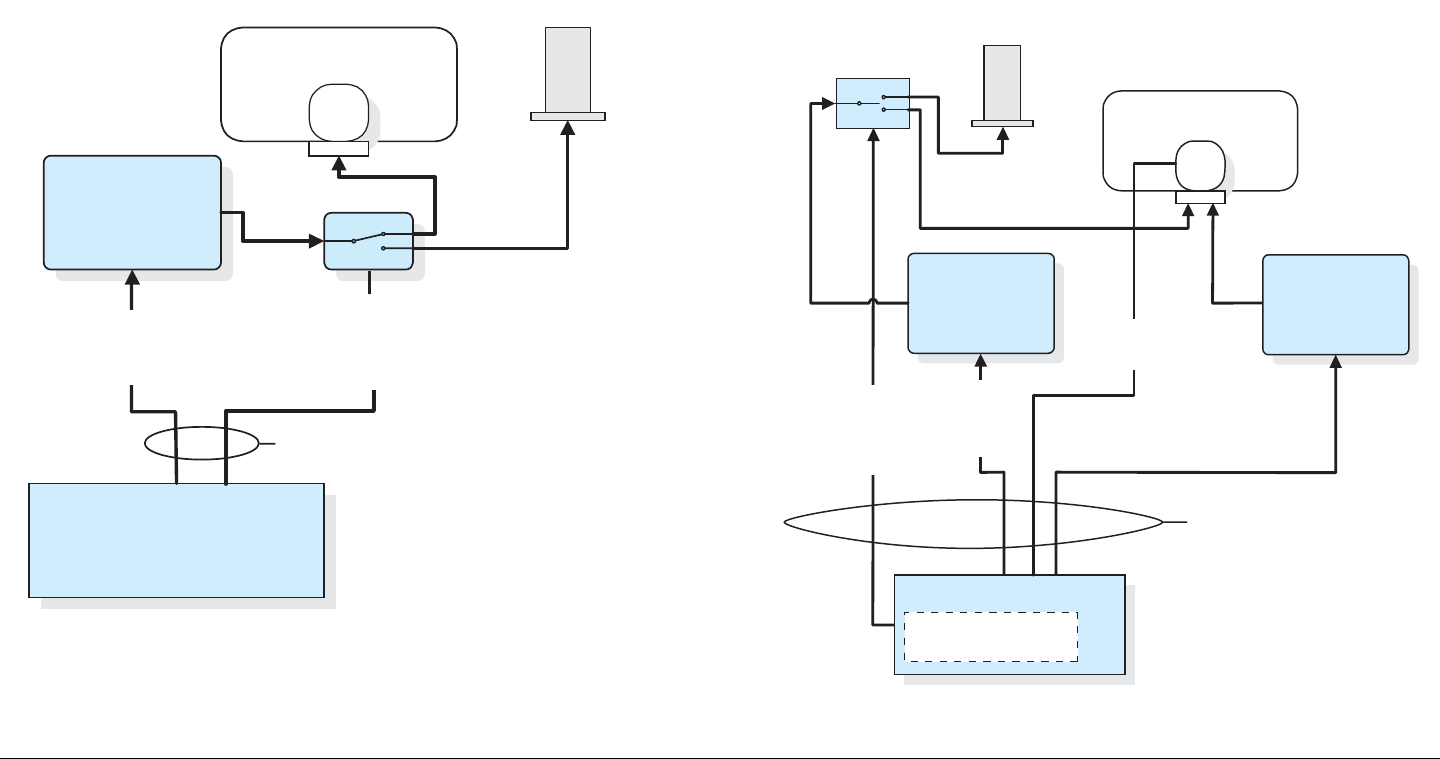
2.7.1 Single-Band/Dual Antenna Transmission
The antenna configuration for single-band transmission using
either an omni antenna or a directional antenna with one IDU
and one ODU is shown in Figure 2-9. The RF switch allows
switching between the two types of antennas.
Figure 2-9: Single-Band Transmission with Two Antennas
MRC RF SWITCH
OmniPole
MTX5000 IDU
ANTENNA
SWITCH
POWER &
CONTROL
NYCOIL CONDUIT
MPEG Encoder &
COFDM Modulator
Directional
MTX5000 ODU
70 MHz IF
+ CONTROL
+ POWER
2.7.2 Dual-Band Non-Simultaneous
Transmission
Figure 2-10 illustrates the antenna configuration for non-
simultaneous transmission using one IDU and two ODUs. In this
example, the ODUs are operating on 2 GHz and 7 GHz bands.
In addition, an RF switch allows switching between an omni and
a directional antenna.
Figure 2-10: Dual Band Non-Simultaneous Transmission
RF SWITCH OmniPole
MTX5000 ODU
1.99-2.5 GHz
MTX5000 IDU
6.4-7.1 GHz
ANTENNA
SWITCH
POWER/
CONTROL
POLARIZATION
SWITCH
MPEG Encoder &
COFDM Modulator
Directional
NYCOIL CONDUIT
MTX5000 ODU
70 MHz IF
+ POWER
+ CONTROL
70 MHz IF
+ POWER
+ CONTRO
L
Product Description 2-10MTX5000 User and Technical Manual
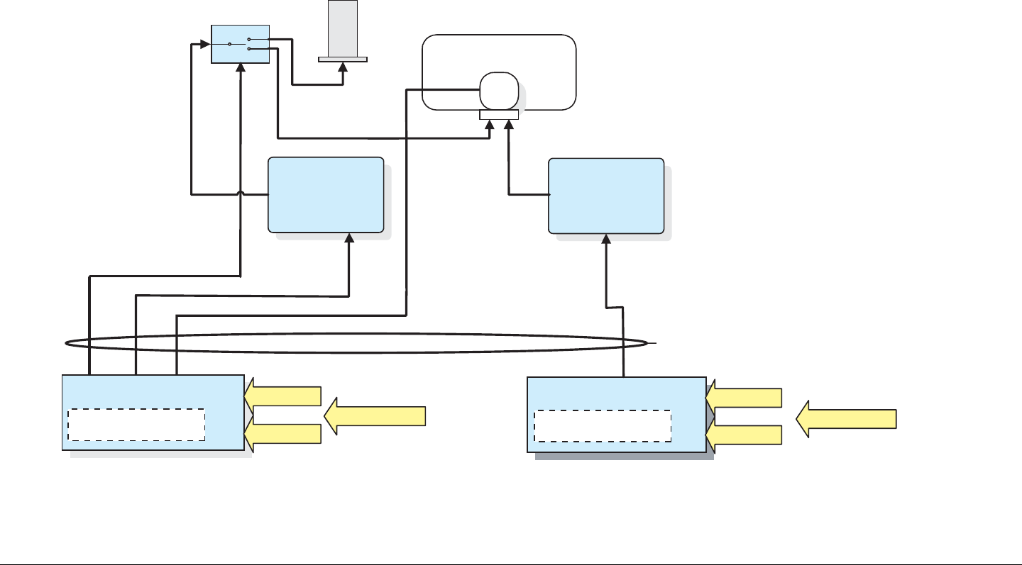
2.7.3 Dual-Band Simultaneous Transmission
Figure 2-11 illustrates the antenna configuration for simultaneous
transmissions using two IDUs and two ODUs. In this example,
the ODUs are operating on the 2 GHz and 7 GHz bands. In
addition, an RF switch allows switching one of the ODUs
between an omni and a directional antenna.
Figure 2-11: Dual-Band Simultaneous Transmission
OmniPole
MTX5000 ODU
1.99-2.5 GHz 6.4-7.1 GHz
NYCOIL CONDUIT
POLARIZATION
SWITCH
MTX5000 IDU
MPEG Encoder &
COFDM Modulator MPEG Encoder &
COFDM Modulator
Directional
RF SWITCH
2 Analog Audio
Analog Video
Digital Video + Audio
SDI
DVB/ASI
2 Analog Audio
Analog Video
Digital Video + Audio
SDI
DVB/ASI
ANTENNA SWITCH
POWER & CONTROL
MTX5000 ODU
MTX5000 IDU
70 MHz IF
+ POWER
+CONTROL
70 MHz IF
+ POWER
+CONTROL

Product Description 2-11MTX5000 User and Technical Manual
2.8 Operating System Modes
2.8.1 General
The MTX5000 IDU offers two levels of operating system modes,
designed to match the needs of different personnel. These
operating modes are the Normal User Mode and the System
Setup Mode.
Regardless if you are operating in the normal user mode or in the
system setup mode, you can read the current settings using the
front panel color LCD display panel with either the touch screen
or the function keys. The MTX5000 IDU internal software
automatically detects what hardware is installed in the system
and applies the appropriate configuration.
The MTX5000 IDU also offers the ability to operate the system
either locally using the IDU front panel color LCD display panel
with either the touch screen or the function keys, or remotely via
an Ethernet connection to a PC at a remote location.
2.8.2 Normal User Mode
For the field operator, the MTX5000 IDU provides multiple
Presets that can be selected from the front panel. Each Preset is
configured with options applicable to the configuration of your
MTX5000 IDU.
Each Preset controls key parameters such as modulation and
audio and video settings. See ”Using the MTX5000 Screens in
Local Mode” on page 3-10 for additional information.
All normal user mode operations may be performed either locally
at the IDU or remotely via the Ethernet from a PC at a remote
location. Normal user mode operations may also be performed
remotely during mobile operations using the optional Remote
Access Subnotebook PC. See ”Using the MTX5000 in Remote
Mode” on page 3-60 for additional information.
2.8.3 System Setup Mode
For the advanced operator and technical staff, the MTX5000 IDU
allows password control of parameters in the MTX5000. For
additional information on the system setup mode, see ”Advanced
Operations” on page 5-1.
System setup mode operations may be performed locally at the
MTX5000 IDU using the front panel color LCD display panel with
either the touch screen or the function keys or remotely using the
remote web page software.
2.9 For More Information
Additional detailed technical information about the MTX5000 is
listed below:
Topic Chapter
Routine Operation See Chapter 3, “Routine
Operation”
Advanced Operation See Chapter 5, “Advanced
Operations”
Installation See Chapter 6, “ Installation”
Connections to other
equipment See Chapter 6, “ Installation”
Supported Repairs and
Repair Parts See Chapter 7,
“Replacement Parts and
Supported Repairs”
Theory of Operation See Chapter 8, “Theory of
Operation”

Product Description 2-12MTX5000 User and Technical Manual
3
Routine Operation 3-1MTX5000 User and Technical Manual
Routine Operation
3.1 Chapter Overview
This chapter provides basic information that will enable you to
operate your MTX5000 Transmitter System (MTX5000).
Here are the topics covered:
Topic Page
Overview of Controls, Indicators, and Connectors 3-2
MTX5000 IDU Controls, Indicators, and
Connectors 3-2
MTX5000 ODU Connectors 3-6
Preparing for Operation 3-7
Mobile Installation 3-7
Powering the MTX5000 System 3-7
Using the MTX5000 Screens in Local Mode 3-10
Overview 3-10
Main Screen 3-11
Color LCD Display Panel 3-13
Touch Screen and Function Keys 3-13
Navigation Between Main and Status Screens 3-14
Transmitter Operation Buttons 3-14
Local/Remote Control Status Button 3-16
Setup Screen Options 3-16
Radio Screen Options 3-17
Select Local/Remote Operation Mode 3-20
MTX5000 Local Operations 3-23
Select Preset 3-24
Select RF Band 3-27
Select/Customize Operating Channels 3-30
Select Channel Offset 3-32
Select Antenna 3-33
Select Antenna Polarization 3-34
Enable/Disable Transmitter 3-35
Select High/Low Power Mode 3-36
Monitor ODU Status 3-36
Monitor IDU Status 3-37
Monitor SUM Errors 3-38
Monitor Current Preset Status Settings 3-38
Perform PA Voltage Adjust Setup 3-44
Perform RF Level Adjust 3-49
Select Color Bar Generator Mode 3-52
Set Time and Date 3-54
Perform IDU Diagnostics 3-56
Review System Information 3-57
Set Last PA State 3-58
Using the MTX5000 in Remote Mode 3-60
Overview 3-60
Remote Screen Display 3-61
Remote Configuration Setting Selections 3-64
Transmitter Controls 3-66
Alerts 3-66
Remote Location Operations 3-67
Select Preset 3-67
Select RF Band and Channel Plan 3-68
Select Operating Channel 3-69
Routine Operation 3-2MTX5000 User and Technical Manual Routine Operation 3-2MTX5000 User and Technical Manual
3.2 Overview of Controls, Indicators,
and Connectors
This section describes the controls, indicators, and connectors
used on the MTX5000 Indoor Unit (IDU) and Outdoor Unit
(ODU).
Select Antenna 3-70
Select Frequency Offset 3-70
Select Antenna Polarization 3-70
Enable/Disable Transmitter 3-71
Select High/Low RF Power Mode 3-71
Monitor Alerts 3-72
Routine vs. Advanced Operation Configuration
Settings 3-73
3.2.1 MTX5000 IDU Controls, Indicators, and
Connectors
Each of the controls, indicators, and connectors contained on the
MTX5000 IDU are described in the following paragraphs.
Controls and indicators contained on all configurations of the
IDU are identical and are identified in Figure 3-1.
Controls, indicators, and connectors contained on the front panel
of the IDU are described in the following paragraphs.
Topic Page
Power Switch 3-3
Color LCD Display Panel with Touch Screen 3-3
Alphanumeric Keypad 3-3
Function keys 3-3
USB 2.0 Connector 3-3
Figure 3-1: MTX5000 IDU Front Panel Controls, Indicators, and Connector
1
4
GHI
7
PQRS
*
Shift
2
ABC
5
JKL
8
TUV
0
3
DEF
6
MNO
9
WXYZ
SEL
#Space
MTX5000
Power
Switch
Color LCD Display Panel
with Touch Screen Alphanumeric
Keypad Function
Keys USB 2.0
Connector

Routine Operation 3-3MTX5000 User and Technical Manual
Power Switch The power switch is located on the front panel
and controls application of power to the MTX5000 system.
When power is applied to the MTX5000 system, the symbol on
the switch illuminates.
Color LCD Display Panel with Touch Screen The front panel
color LCD display panel with touch screen is mounted on a tilting
mechanism that allows you to adjust the viewing angle, based on
the rack-mounted location and lighting conditions. The color
LCD display panel is used in conjunction with the touch screen
or function keys to make option selections displayed on the color
LCD display panel.
The color LCD display panel provides user interface control of
the MTX5000 IDU and provides full monitoring capability for the
system. The color LCD display panel, in conjunction with the
touch screen or function keys, allows you to perform the
following:
• Recall Presets
• Select RF head and/or RF band
• Select operating channel
• Select channel offset
• Select between two antennas
• Set antenna polarization
• Select between low and high power operation of the
transmitter
• Turn the transmitter on and off
• Monitor error conditions within the MTX5000 IDU and the
ODU
• Monitor RF power output
• Monitor individual Preset settings
• Select local or remote operating mode.
All option selections are made using the color LCD display panel
and either the color LCD display panel touch screen or the
function keys, as required.
Alphanumeric Keypad (The front panel alphanumeric keypad
is currently inactive.)
Function keys The Left, Right, Up, and Down arrow keys may
be used to select options displayed on the color LCD display
panel. Pressing the SEL (select) key selects the option button
required after the option button has been selected using the
arrow keys. For ease of operation in low-light conditions, the
keys are illuminated when power is applied to the unit.
USB 2.0 Connector The front panel USB 2.0 connector
provides the connection required to upgrade software into the
MTX5000 using a USB flash drive and a USB-A to USB-B
adapter.
Rear panel connectors contained on the IDU are shown in
Figure 3-2 on page 3-4 and are described in the following
paragraphs.
Routine Operation 3-4MTX5000 User and Technical Manual Routine Operation 3-4MTX5000 User and Technical Manual
Figure 3-2: MTX5000 IDU Rear Panel Connectors - Typical
ETHERNET
RTN DATA
WAYSIDE
ATPC
AUDIO
1234
+ G - + G - + G - + G -
SUM
ALARM
AES/EBU VIDEO IN
BB IN IF MON
AC-3
SMPTE 302
ASI 1 HD-SDI ASI 2
IF IN VID MON SDI/ASI
ANT
CONTROL
RFU POWER OUT
RFU 1 RFU 2
H
V
LCP
ANT2
BAND2
GND
+
- - + +
- - + +
12
POWER IN
+ G - + G -
12
ANT
CONTROL
RFU POWER OUT
RFU 1 RFU 2
H
V
LCP
ANT2
BAND2
GND
+
- - + +- - + +
12
ETHERNET WAYSIDE AUDIO
1 thru 4
RTN DATA
BB IN IF MON ASI 1 HD-SDI ASI 2
POWER IN
ATPC SUM
ALARM AES/EBU
1 and 2 VIDEO
IN
RFU 2
(Triax
Option)
RFU 1
(Triax
Option)
ANT
CONTROL
AC-3
SMPTE 302 IF IN VID
MON
SDI/ASI
RFU 1 (Type “N”
or TNC Options)
RFU 2 (Type “N”
or TNC Options)
AC Power
Fuse
(Behind
Cover)
RFU POWER OUT (With
Type “N” or TNC RFU 1
and RFU 2 Connector
Options Only)
Topics covered are as follows:
Topic Page
ETHERNET Connector 3-5
WAYSIDE Connector 3-5
AUDIO 1 thru 4 Connectors 3-5
BB IN Connector 3-5
IF MON Connector 3-5
ASI 1 Connector 3-5
HD-SDI Connector 3-5
ASI 2 Connector 3-5
RFU POWER OUT Connector 3-5
AC Power Fuse 3-5
POWER IN Connector Assembly 3-5
RTN DATA Connector 3-5

Routine Operation 3-5MTX5000 User and Technical Manual
ETHERNET Connector The ETHERNET RJ-45 connector
provides connection via your web browser to a PC at a remote
location or to the optional Remote Access Subnotebook PC for
remote control of the MTX5000 IDU.
WAYSIDE Connector The WAYSIDE 9-pin male D-connector
provides connection for the MPEG encoder Wayside input data.
AUDIO 1 thru 4 Connectors The AUDIO 1 thru 4 male 3-pin
Weidmuller connectors provide analog/digital switchable stereo
audio signal inputs to the FMT or MPEG modules.
BB IN Connector The BB IN 75 ohm BNC female connector
provides baseband input video from an external baseband
source.
IF MON Connector The IF MON 75 ohm BNC female
connector provides a 70 MHz output for external signal
monitoring purposes.
ASI 1 Connector (The 75 ohm BNC female ASI 1 connector is
currently inactive.)
HD-SDI Connector The HD-SDI 75 ohm BNC female connector
provides the HD-SDI data stream input to the MTX5000.
ATPC Connector 3-5
SUM ALARM Connector 3-5
AES/EBU Connectors 3-5
VIDEO IN Connector 3-5
AC-3 SMPTE 302 Connector 3-5
IF IN Connector 3-5
VID MON Connector 3-6
SDI/ASI Connector 3-6
ANT CONTROL Connector 3-6
RFU 1 Connector 3-6
RFU 2 Connector 3-6
ASI 2 Connector (The 75 ohm BNC female ASI 2 connector is
currently inactive.)
RFU POWER OUT Connector The RFU POWER OUT 8-pin
Weidmuller male connector is present only if the RFU 1 and
RFU 2 connectors are type “N” or TNC connectors. The RFU
POWER OUT connector is not present on IDU configurations
that have Triax RFU 1 and RFU 2 connectors.
The RFU POWER OUT connector provides DC power to
Outdoor Units (ODU) RFU 1 and RFU 2 via DC on coax.
AC Power Fuse The AC power fuse provides AC input power
protection for the unit.
POWER IN Connector Assembly The POWER IN connector
assembly provides connection to the removable external AC
power cable. The AC power connector contains the AC input
power fuse.
RTN DATA Connector (The RTN DATA RJ-45 connector is
currently inactive.)
ATPC Connector (The ATPC 9-pin male D-connector is
currently inactive.)
SUM ALARM Connector (The SUM ALARM 2-pin male
Weidmuller connector is currently inactive.)
AES/EBU Connectors The AES/EBU 1 and 2 male 3-pin
Weidmuller connectors provide channel 1 and 2 external AES/
EBU digital audio inputs to the unit.
VIDEO IN Connector The 75 ohm BNC female VIDEO IN
connector receives the analog video input to the unit.
AC-3 SMPTE 302 Connector (The AC-3 SMPTE 302 75 ohm
BNC female connector is currently inactive.)
IF IN Connector The IF IN 75 ohm BNC female connector
provides the 70 MHz IF input to the unit.
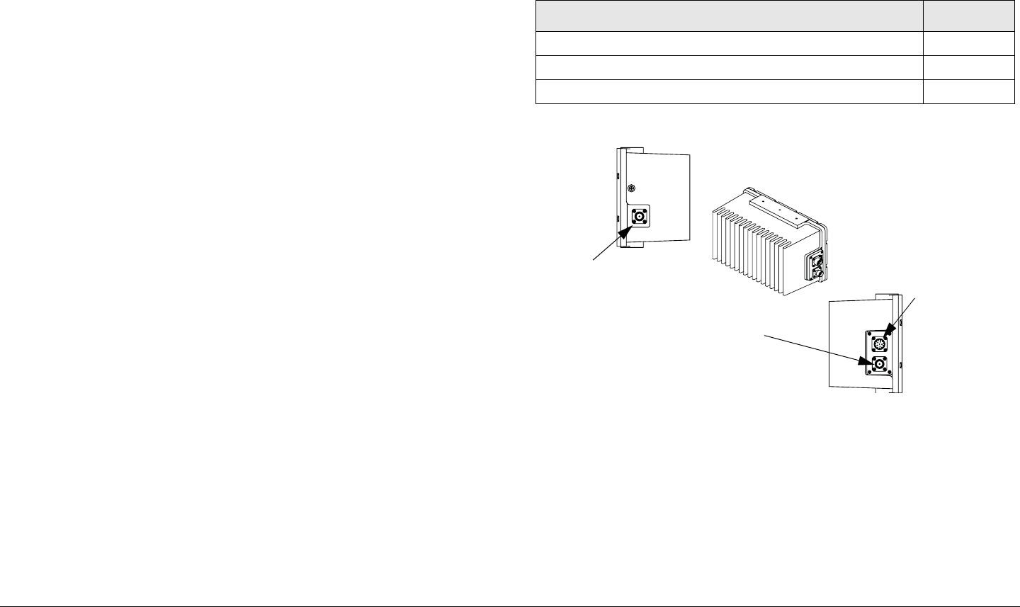
Routine Operation 3-6MTX5000 User and Technical Manual
VID MON Connector The VIDEO MON 75 ohm BNC female
connector provides a video output for external monitoring
purposes.
SDI/ASI Connector The SDI/ASI 75 ohm BNC female
connector provides SDI and ASI inputs to the unit.
ANT CONTROL Connector The ANT CONTROL 7-pin male
Weidmuller connector provides control for antenna polarization,
antenna band selection, and the RF switch. The connector also
provides DC power for the antenna and the RF switch.
RFU 1 Connector The RFU 1 connector will either be a Triax,
type “N”, or TNC, depending upon the options ordered with your
MTX5000 system. This connector provides 70 MHz IF output to
RF unit 1.
If your IDU contains a Triax RFU 1 connector, the RFU POWER
OUT connector will not be present. If your IDU contains a Triax
connector, 70 MHz IF will be supplied to RFU 1 and DC power to
RFU 1 will be supplied via DC on coax from the IDU.
If your IDU contains a type “N” or TNC RFU 1 connector, 70 MHz
IF will be supplied to RFU 1 and DC power to RFU 1 will be
supplied via the RFU POWER OUT connector.
RFU 2 Connector The RFU 2 connector will either be a Triax,
type “N”, or TNC, depending upon the options ordered with your
MTX5000 system. This connector provides 70 MHz IF output to
RF unit 2.
If your IDU contains a Triax RFU 2 connector, the RFU POWER
OUT connector will not be present. If your IDU contains a Triax
connector, 70 MHz IF will be supplied to RFU 2 and DC power to
RFU 2 will be supplied via DC on coax from the IDU.
If your MTX5000 contains a type “N” or TNC RFU 1 connector,
70 MHz IF will be supplied to RFU 2 and DC power to RFU 2 will
be supplied via the RFU POWER OUT connector.
3.2.2 MTX5000 ODU Connectors
Controls and indicators contained on the MTX5000 ODU (See
Figure 3-3) are described in the following paragraphs. Topics
covered are as follows:
Figure 3-3: MTX5000 ODU Connectors
RF OUT Connector The Type “N” RF OUT connector provides
the RF output connection to the antenna or antenna switch. This
connector is a type “N” connector for all configurations of the
ODU.
RF IN Connector The RF IN connector is either a Type “N”,
TNC, or Triax, as applicable to the options ordered with your
MTX5000 system. The RF IN connector receives 70 MHz IF
from the IDU for up-conversion to the 2 GHz or 7 GHz bands and
amplification, as required.
Topic Page
RF OUT Connector 3-6
RF IN Connector 3-6
POWER Connector 3-7
RF OUT
RF IN
IDU
RF OUT
Connector POWER
Connector
RF IN
Connector

Routine Operation 3-7MTX5000 User and Technical Manual
If the RF IN connector option is a Type “N” or TNC, DC power to
the ODU is provided from the IDU via the ODU POWER
connector. If the RF IN connector is a Triax connector, DC
power and control is provided to the ODU from the IDU via the
RF IN connector.
POWER Connector The POWER connector receives DC
power from the IDU via the wiring harness between the IDU and
the ODU. The POWER connector is present on the ODU only if
your MTX5000 system contains either the TNC or Type “N” RF
IN connector options.
3.3 Preparing for Operation
The procedures required to use the color LCD display panel with
touch screen and function keys locally, in the normal user mode
of operation, are contained in the following paragraphs.
The color LCD display panel is used in conjunction with the color
LCD display panel touch screen or the function keys to make
selections displayed on the color LCD display panel.
The normal user mode is designed for you to recall existing
system Presets in order to properly transmit the video stream
back to the studio from a remote location.
Along with recalling a Preset that is appropriate for a given
broadcast situation, you can select between two antennas,
select between two ODUs (if your system contains two ODUs),
select an operating band, select a channel within the operating
band, select a channel offset, and select antenna polarization.
You can also select between high and low power operation of the
transmitter, you can turn the transmitter on and off, and you can
monitor any fault conditions that may exist within the MTX5000
IDU and/or ODU.
When power is applied to the MTX5000, it automatically enters
the local normal user operation mode. The MTX5000 will
remember the last settings that were in use, regardless if they
were a stored Preset or user-defined settings, and will return to
those settings. If the MTX5000 was transmitting when power
was removed, the IDU will not automatically return to the
transmit mode. If the MTX5000 was in the remote mode when
power was removed, the IDU will not return to the remote mode.
3.3.1 Mobile Installation
For mobile applications, the MTX5000 is typically mounted in a
bulkhead or compartment in a 19-inch (48.3 cm) rack and the
ODU is mounted on the vehicle antenna mast. The cabling is
permanently installed and power comes from the mobile AC
power source.
Each installation or deployment will have its own specific tasks
according to the application and the installed hardware options.
For additional information, refer to the “ Installation” section on
page 6-1.
3.3.2 Powering the MTX5000 System
CAUTION Corruption of software contained in the
MTX5000 may occur if proper power down
or power up of the MTX5000 does not
occur.
The MTX5000 must be properly powered up and powered down
to prevent possible corruption of the software contained in the
radio. It will take approximately 60 seconds for the MTX5000 to
power up properly. As with a personal computer, it takes time for
the internal software to become initialized and the Main screen to
be displayed.

Routine Operation 3-8MTX5000 User and Technical Manual
When the power switch is pressed to on and power is applied to
the MTX5000, a blank display initially appears on the color LCD
display panel. After a short delay, the introduction screen will be
displayed and a status bar will appear on the introduction screen.
Then, after a very short delay, the Main screen will be displayed.
Power to the MTX5000 must never be cycled off and on without
a minimum delay of 10 seconds between removal of power and
application of power. Just like a personal computer, a proper
shutdown of the MTX5000 is required to prevent corruption of
software.
CAUTION The MTX5000 must never be powered
down when the progress bar is displayed.
The software will become corrupted and the
MTX5000 may have to be returned to the
factory for repair.
Conversely, power to the MTX5000 must never be cycled to on
and then immediately to off, as corruption of software contained
in the radio may also occur. The MTX5000 must only be
powered down when the Main screen is displayed.
CAUTION Under no circumstances should you remove
and re-apply power to the MTX5000 when
the progress bar is displayed during a self-
recovery.
The software will become corrupted and the
MTX5000 may have to be returned to the
factory for repair.
If power to the MTX5000 is lost and is then re-applied
immediately or if the power switch is set to off and then to on in
less than 10 seconds, the MTX5000 internal software will
attempt a self-recovery when the power switch is set to on.
During the self-recovery process, the blank screen will initially
appear, followed by the introduction screen. The progress bar
will appear on the introduction screen, but progress will be much
slower than during a normal power up. Do not interrupt the self-
recovery process by cycling power to off and then to on, as
software corruption will occur.
Power Up
The steps required to properly power up the MTX5000 system
are contained in the following steps.
CAUTION If power is accidentally lost or if the power
switch is pressed to off, do not immediately
power up the MTX5000 again.
Internal software corruption may occur if
power is applied immediately after a power
loss or if the power switch is pressed to off
and immediately back to on.
To avoid possible software corruption, wait a
minimum of 10 seconds before applying
power or before pressing the power switch
to on.
Note If you are unsure of the power requirements or
connections to the MTX5000, refer to the
“ Installation” section on page 6-1.
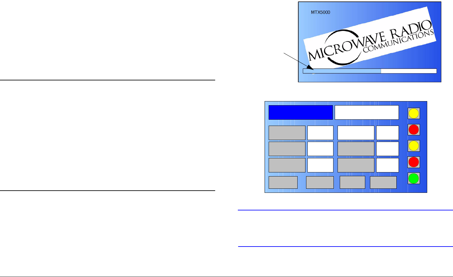
Routine Operation 3-9MTX5000 User and Technical Manual
1. Verify the power cable is properly connected to the
MTX5000 IDU rear panel AC POWER IN connector.
2. Verify all coaxial cables and cable connectors are
properly connected to the rear panel connectors and
verify the ODU or ODUs, as applicable to your system
options, are properly connected.
3. Connect the MTX5000 IDU power cable to AC power
of the correct type and voltage.
4. Verify the power source is turned on.
5. Press the power switch and observe the symbol on the
switch illuminates.
Notes When power is applied to the MTX5000, it will
automatically enter the local normal user mode of
operation.
The MTX5000 will return to the last settings that
were in use when the unit was powered down, but
the MTX5000 will not resume transmitting if the unit
was transmitting when it was powered down.
If the MTX5000 was in the remote mode when
power was removed, the IDU will not return to the
remote mode.
6. The normal power-up sequence is as follows:
- After approximately 30 seconds, the introduction
screen will be displayed on the color LCD display
panel. See Figure 3-4.
- A progress bar will also be displayed indicating power
up progress and, approximately 30 seconds after the
introduction screen is displayed, the Main screen will
be displayed on the color LCD display panel. See
Figure 3-5.
Figure 3-4: Introduction Screen
Figure 3-5: Main Screen - Typical
CAUTION Always wait a minimum of 5 seconds after
the Main screen is displayed following
power up before selecting a Preset.
7. Select the Preset required per “Select Preset” on
page 3-24.
Progress
Bar (Typical)
Channel 1 0Offset
Antenna Ant. Pol.Antenna1 H
RFU1
No RF
RF Band
Preset A Analog
4.83 & 5.8, 3MHz Vid Dev
RF Output XX
dBm
<- Status Setup Status ->
PA Off
SUM
ODU
IDU
RF
L/R
L
L
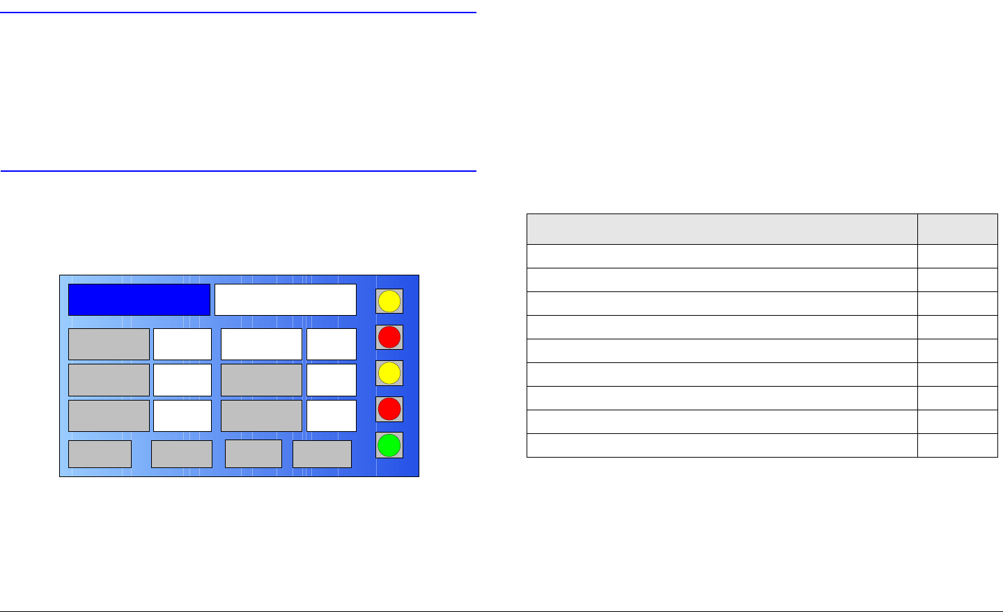
Routine Operation 3-10MTX5000 User and Technical Manual
Power Down
The steps required to properly power down the MTX5000 system
are contained in the following steps.
CAUTION To allow proper shutdown of MTX5000
internal software, the progress bar must not
be displayed when the power switch is
pressed to off.
Failure to properly power down the
MTX5000 may corrupt the internal software.
1. Verify the Main screen is displayed on the color LCD
display panel. See Figure 3-6.
Figure 3-6: Main Screen - Typical
2. Press the power switch and observe the symbol on the
switch goes off.
3. Set the power source off, as required.
Channel 1 0Offset
Antenna Ant. Pol.Antenna1 H
RFU1
No RF
RF Band
Preset A Analog
4.83 & 5.8, 3MHz Vid Dev
RF Output XX
dBm
<- Status Setup Status ->
PA Off
SUM
ODU
IDU
RF
L/R
L
L
3.4 Using the MTX5000 Screens in
Local Mode
Once the MTX5000 is powered up, you will be able to monitor
and/or change certain operating parameters through the use of
the options displayed on the color LCD display panel. All options
are dependent upon the actual configuration of your MTX5000
and the Preset settings.
The sections listed in Table 3-1 describe use of the screens
displayed on the color LCD display panel in the local operating
mode.
3.4.1 Overview
As you use the MTX5000, you will interact exclusively with the
color LCD display panel. All operations are performed using
either the color LCD display panel touch screen or function keys
to select options. See Figure 3-7 on page 3-11.
Table 3-1: Using MTX5000 Menus
Topic Page
Overview 3-10
Main Screen 3-11
Color LCD Display Panel 3-13
Touch Screen and Function Keys 3-13
Navigation Between Main and Status Screens 3-14
Transmitter Operation Buttons 3-14
Local/Remote Control Status Button 3-16
Setup Screen Options 3-16
Radio Screen Options 3-17
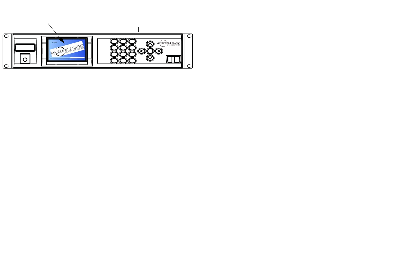
Routine Operation 3-11MTX5000 User and Technical Manual
Figure 3-7: MTX5000 Front Panel
1
4
GHI
7
PQRS
*
Shift
2
ABC
5
JKL
8
TUV
0
3
DEF
6
MNO
9
WXYZ
SEL
#Space
MTX5000
Color LCD Display
Panel with Touch
Screen
Function
Keys
3.4.2 Main Screen
The Main screen is your starting point for navigating through the
various status screens. The Main screen provides access to the
current values of the selected Preset options.
The top level menu hierarchy is illustrated in Figure 3-8 on
page 3-12. From the top level menu page, you will descend into
the lower levels of the menu hierarchy until the operational
parameter required is reached. All routine operations and
options are described in the following paragraphs.
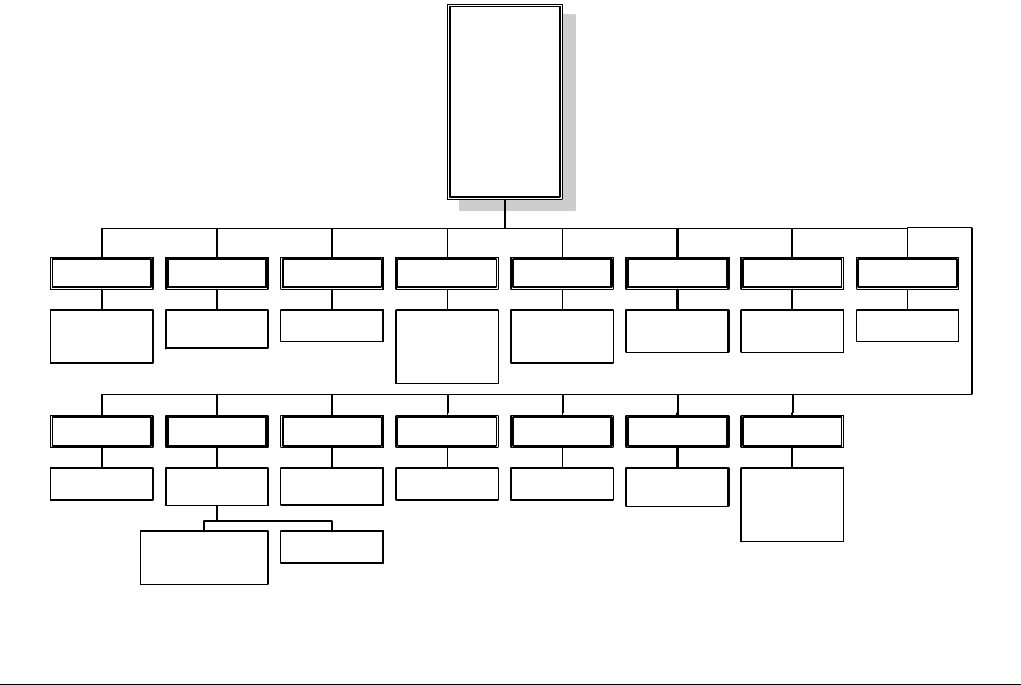
Routine Operation 3-12MTX5000 User and Technical Manual Routine Operation 3-12MTX5000 User and Technical Manual
Figure 3-8: Top Level Main Menu Hierarchy
Main Page
Preset
RF Band
RF Output
Channel
Offset
Antenna
Ant. Pol.
PA
Status
Setup
RF
ODU
IDU
SUM
L/R
Preset
Select Preset A
thru J or Preset 1
thru XX, as
required
RF Band
Select RFU1 or
RFU2, as
required
RF Output
Monitor current
RF output level
Channel Offset Antenna Ant. Pol.
Select channel 1
thru 10 (2 GHz
band) or channel
1 thru 14 (7 GHz
band), as
required
Select – (minus),
0 (center), or +
(plus), as
required
Select Ant. 1 or
Ant. 2, as
required
Select H, V, RC,
or LC, as
required
PA
Select PA or PA
Off, as required
Status
Observe current
Preset settings
Setup
Select User or
Radio, as
required
User option is
Password protected.
See Advanced
Operations Chapter
Radio option
selected
RF
Select L (Low) or
H (High) power,
as required
ODU
Monitor current
ODU status
IDU
Monitor current
IDU status
SUM
Monitor current
summary (SUM)
alarm status
L/R
Select L (Local)
operation mode.
R (Remote) mode
can only be
selected in Setup
mode
Each menu page has multiple selections available. Once you
have navigated to the menu page required, you can observe or
change an operating parameter, as required. To observe or
change a parameter, different screens are displayed, indicating
the different options available.
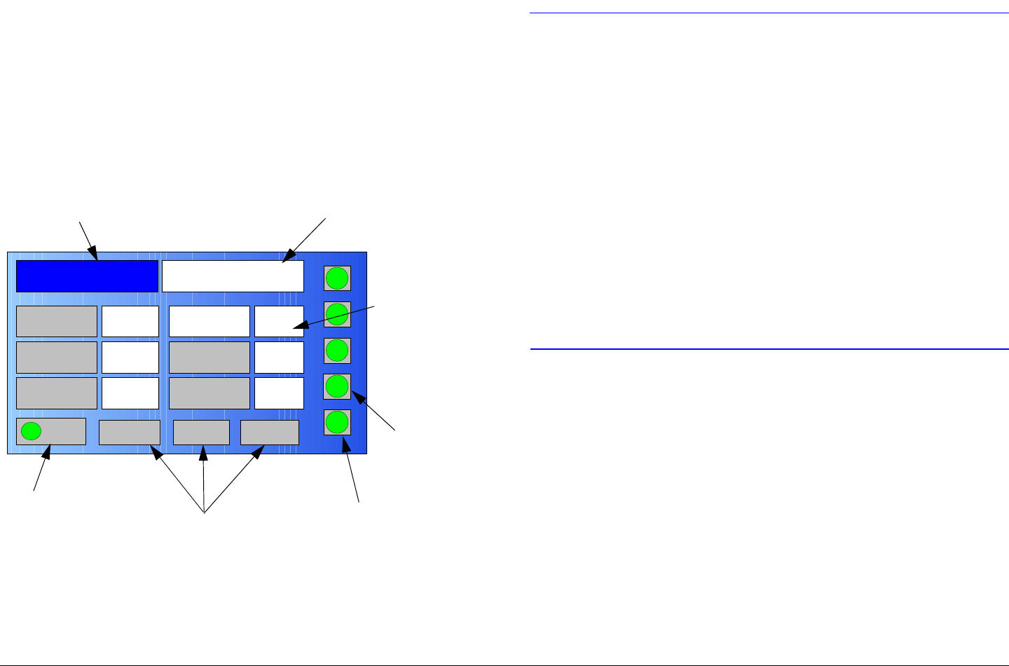
Routine Operation 3-13MTX5000 User and Technical Manual
3.4.3 Color LCD Display Panel
All menus and screens displayed on the color LCD display panel
consist of active option buttons, setting indicators, or status
indicators. See Figure 3-9. The currently selected active option
button will be blue with white text. Active option buttons that may
be selected are grey with black text or white text on the blue
background (e.g., the Preset option button). Grey option buttons
with dark grey text are inactive and cannot be selected.
Figure 3-9: Color LCD Display Panel - Typical
On the Main screen, a brief description of the currently selected
Preset is displayed in white with red text, surrounded by a black
outline.
Channel 1 0Offset
Antenna Ant. Pol.Antenna1 V
RFU2
7US
RF Band
Preset A Analog
4.83 & 5.8, 3MHz Vid Dev
RF Output XX
dBm
<- Status Setup Status ->
PA On
SUM
ODU
IDU
RF
L/R
H
L
Setting
Indicators
(Black
Outlines) -
Typical
Active Option Buttons (Blue
Background) - Typical
PA Operation
Button Navigation Option
Buttons - Typical
Current Preset
Description - Typical
Status
Indicators
Local/Remote
Status Button
3.4.4 Touch Screen and Function Keys
CAUTION Avoid damage to the color LCD display
panel!
The color LCD display panel touch screen
may be damaged if a sharp, hard-pointed
object, such as a pencil or a pen, is used to
select the displayed options.
Touch screen options must only be selected
using your fingers, a soft-pointed stylus, or
the front panel function keys.
Damage to the color LCD display panel
caused by using a hard-pointed object or
other misuse may void your warranty on
the MTX5000 IDU.
The color LCD display panel touch screen or function keys may
be used to select active option buttons displayed on the color
LCD display panel. To select a specific active option button
using the touch screen, simply touch the required active option
button on the color LCD display panel to select the option.
When active option buttons are selected, the option button will
change from grey to blue and the text color will change
accordingly. Setting indicators are white with black text,
surrounded by a black outline. Active option buttons are
selected using either the color LCD display panel touch screen
or the function keys.
To use the function keys (See Figure 3-10 on page 3-14) to
select a specific active option, use the Up, Down, Left, and Right
function keys to select the required active option button, press

Routine Operation 3-14MTX5000 User and Technical Manual
the SEL (select) function key, and observe the required option
screen is displayed.
Figure 3-10: Function Keys
3.4.5 Navigation Between Main and Status
Screens
Different Status screens are displayed depending upon the
Preset mode (Analog or Digital) selected. At the bottom of each
Main screen, navigation option buttons are provided that point to
the Status screen(s). When a navigation option button that
points to a Status screen is selected, the applicable Status
screen will be displayed.
At the bottom of most Status screens, navigation option buttons
pointing to the Main screen and the next Status screen, if any,
are provided. When navigation option buttons pointing to the
Main or Status screens are selected, the applicable screen will
be displayed.
3.4.6 Transmitter Operation Buttons
Transmitter operation buttons are displayed on most screens to
indicate or to change the current state of the transmitter.
Transmitter operation buttons are described in the following
paragraphs.
1
4 GHI
7 PQRS
*Shift
2 ABC
5 JKL
8 TUV
0
3 DEF
6 MNO
9WXYZ
SEL
#Space
Function Keys
PA Operation Button The PA operation button status indicator
is blue when selected, is labelled PA Off when the transmitter is
off, indicates PA with an amber button in warm-up mode, and is
green and is labelled PA On when the transmitter is on
(transmitting).
When the PA operation button is selected using the touch screen
or the function keys and SEL key, the state of the transmitter (PA
On or PA Off) will change. The PA status indicator will then
change to the alternate green (on) or grey (off) indicator, as
applicable.
RF Operation Button The RF operation button will display a
blue background when selected. The operation button will
display a yellow status indicator labelled L (low power) when the
transmitter is operating in the low power mode and will display a
green status indicator labelled H (high power) when the
transmitter is operating in the high power mode.
When the RF operation button is selected using the touch screen
or the function keys and SEL key, the functional state of the
transmitter will change and the RF status indicator will change to
the alternate yellow (low power) or green (high power) status
indicator, indicating the current state of the transmitter.
ODU Status Button The ODU status button displays the
current Outdoor Unit (ODU) alarms. The ODU status button will
display a green status indicator to indicate no alarm conditions
exist in the ODU. The ODU status button will display a yellow
status indicator if a minor alarm is detected that does not
adversely affect transmit operations. The ODU status button will
display a red status indicator if the ODU is reporting at least one
major alarm that adversely affects transmit operations.
When the ODU status button is selected using the touch screen
or the function keys and SEL key, the ODU Status screen (See
Figure 3-11 on page 3-15) will be displayed indicating the current
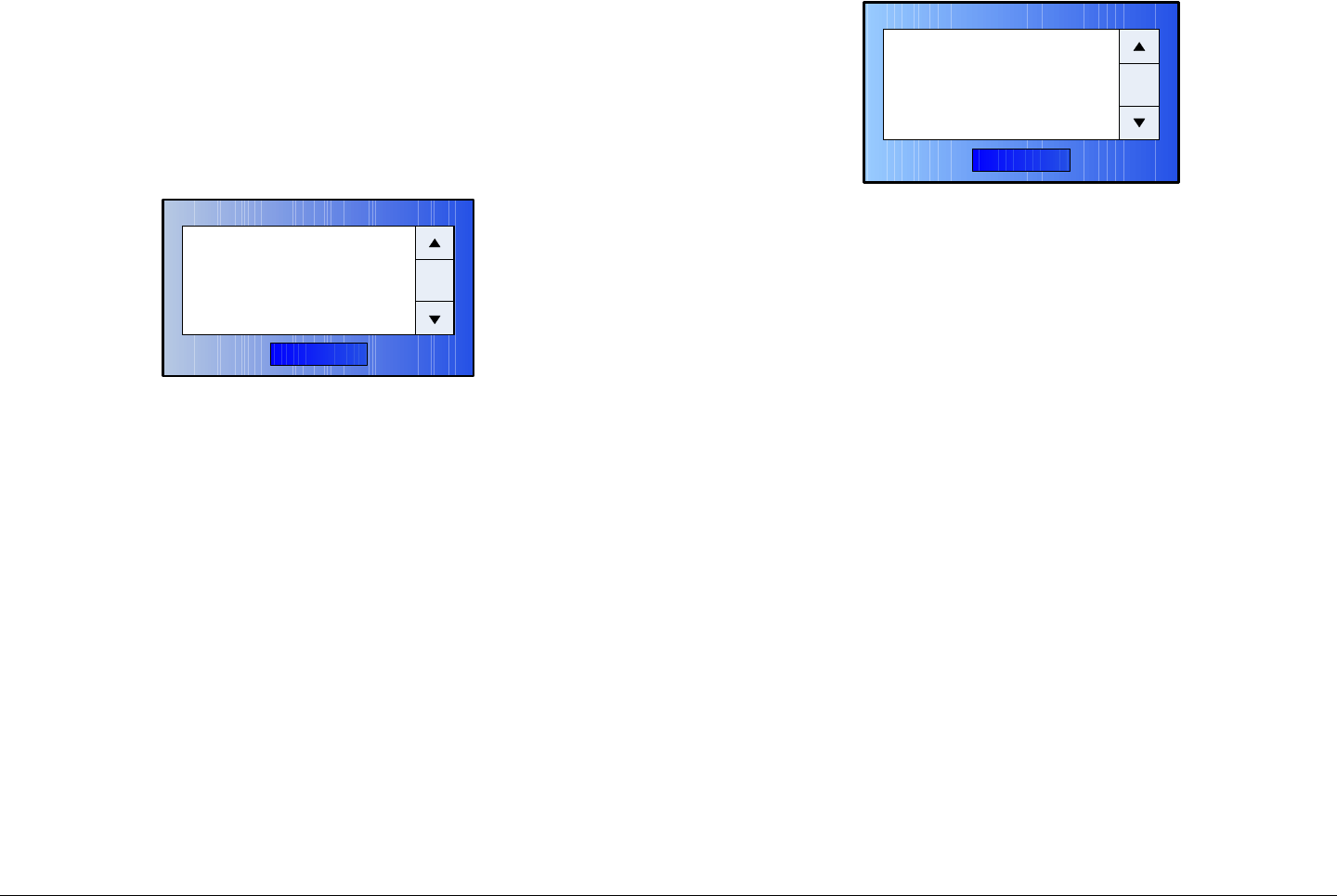
Routine Operation 3-15MTX5000 User and Technical Manual
ODU alarms. If no alarms are present, the dialog box will
indicate No Errors. If alarms are present, the alarms will be
listed in the dialog box. See ”Error Messages” on page 4-1 for a
list of possible alarms that may be listed in the dialog box.
The screen contains an OK option button that, when selected,
removes the screen from the display.
Figure 3-11: ODU Status Dialog Box - Typical
IDU Status Button The IDU status button displays the current
condition of the Indoor Unit (IDU). The IDU status button will
display a green status indicator indicating no alarm conditions
exist in the IDU. The IDU status button will display a yellow
status indicator if a minor alarm is detected that does not
adversely affect transmit operations. The IDU status button will
display a red status indicator if the IDU is reporting at least one
major alarm that adversely affects transmit operations.
When the IDU status button is selected using the touch screen or
the function keys and SEL key, the IDU Status screen (See
Figure 3-12) will be displayed indicating the current status of the
IDU.
OK
ODU Status
xxxxxxxxxxx
Figure 3-12: IDU Status Dialog Box - Typical
If no alarms are present, the dialog box will indicate No Errors.
If alarms are present, the alarms will be listed in the dialog box.
See ”Error Messages” on page 4-1 for a list of possible alarms
that may be listed in the dialog box.
The screen contains an OK option button that, when selected,
removes the screen from the display.
SUM Status Button The SUM status button displays the
summary alarm status. The SUM status button will display a
green status indicator to indicate no alarms exist in the MTX5000
system. The SUM status button will display a yellow status
indicator if a minor IDU and/or ODU alarm is detected that does
not adversely affect transmit operations. The SUM option button
will display a red status indicator if the IDU and/or ODU is
reporting at least one major alarm that adversely affects transmit
operations.
The SUM status button will not display a red status indicator for
all alarm conditions reported by the ODU or the IDU. Only alarm
conditions that are considered major to the operation of the
transmitter will change the state of the SUM status button status
indicator to red.
When the SUM status button is selected using the touch screen
or the function keys and SEL key, the Summary Alarm screen
(See Figure 3-13 on page 3-16) will be displayed indicating the
current status of the MTX5000 system.
OK
IDU Status
xxxxxxxxxxxxxxxxx
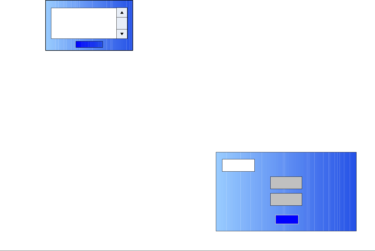
Routine Operation 3-16MTX5000 User and Technical Manual
Figure 3-13: Summary Alarm Dialog Box - Typical
If no alarms are present, the dialog box will indicate No Errors.
If alarms are present, the IDU and/or ODU alarms will be listed in
the dialog box. See ”Error Messages” on page 4-1 for a list of
possible alarms that may be listed in the dialog box.
The screen contains an OK option button that, when selected,
removes the screen from the display.
3.4.7 Local/Remote Control Status Button
The Main page local/remote L/R status button indicates the
MTX5000 is in either the local operation mode or in the remote
operation mode. When the L option is displayed, the status
indicator will be green. When the R option is selected, the status
indicator will be amber.
When the option button is in the L mode, all control operations
must be performed at the MTX5000. When in the R mode and
the MTX5000 is connected via your web browser to a PC at a
remote location or to the optional Remote Access Subnotebook
PC during mobile operations, the operations must be performed
at the remote PC.
You can connect to the MTX5000 from a remote location when
the MTX5000 is in either the local or remote operation mode. If
you are connected to the MTX5000 via your web browser from a
remote location or to the optional Remote Access Subnotebook
PC and the MTX5000 is in the local operation mode, you can
OK
Summary Alarm
xxxxxxxxxxxxxxxxx
monitor status settings from the remote location, but no settings
may be changed from the remote PC. You must be in the remote
operation mode to monitor and control the MTX5000 remotely.
To select the remote operation mode, you must use the Setup
screens. To change from the remote mode to the local mode,
you must select the Main screen L/R status button.
Selection of the local/remote operating mode can only be
performed at the MTX5000. You cannot change the local/
remote operating mode from the remote location. For
information on using the MTX5000 in the remote operating
mode, see ”Using the MTX5000 in Remote Mode” on page 3-60.
3.4.8 Setup Screen Options
The Main screen Setup option button and the associated setup
option screens are described in the following paragraphs.
Setup Screen The Main screen Setup option button provides
you with access to the Setup screen when the Setup option
button is selected. See Figure 3-14.
Figure 3-14: Setup Screen
Setup
User
Main
Radio
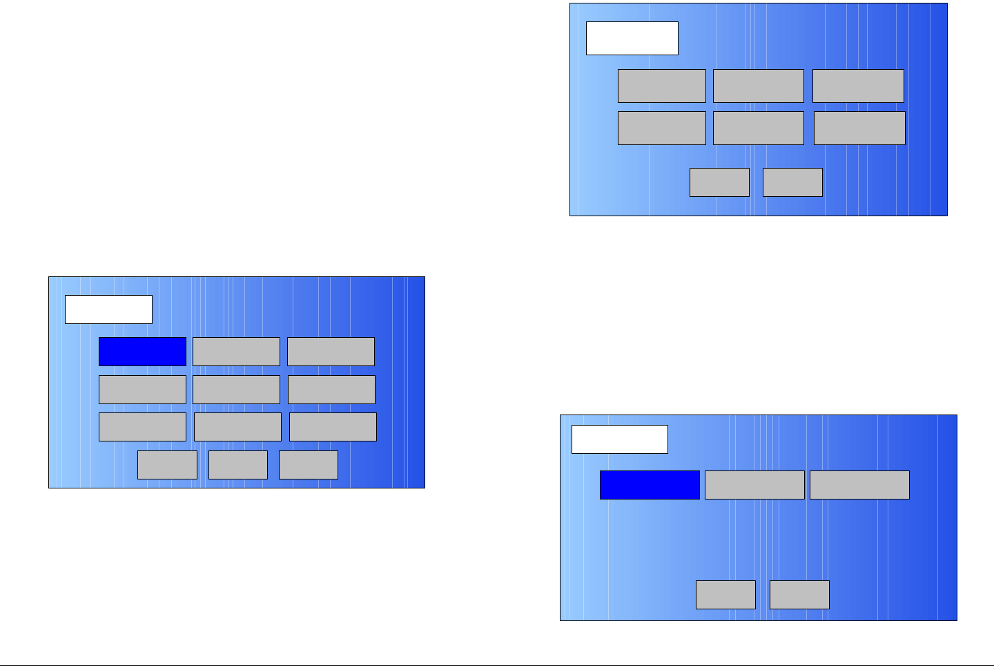
Routine Operation 3-17MTX5000 User and Technical Manual
The Setup screen provides User, Radio, and Main option
buttons. The option buttons are described in the following
paragraphs.
Main Option Button Selection of the Main option button
provides return from the Setup screen to the Main screen.
User Option Button The User option button is password-
controlled and provides access to custom radio Preset settings.
For information on the User option button, see ”Advanced
Operations” on page 5-1.
Radio Option Button Selection of the Setup screen Radio
option button provides entry into the Radio screen. See
Figure 3-15.
Figure 3-15: Radio Screen
Back Option Button Selection of the Radio screen Back
option button provides return from the Radio screen to the
Setup screen.
Main Option Button Selection of the Radio screen Main option
button provides return from the Radio screen to the Main screen.
Next Option Button Selection of the Radio screen Next option
button takes you to the Radio- 2 screen. See Figure 3-16.
Radio
Back
Network Config Level Adjust Color Bars
Calibration
Time & Date
Change Pwd
System Info
License Key
Diagnostics
Next
Main
Figure 3-16: Radio - 2 Screen
3.4.9 Radio Screen Options
The option buttons contained on the Radio screen are described
in the following paragraphs.
Network Config Option Button When the Radio screen
Network Config option button is selected, the Network Config
screen is displayed. See Figure 3-17.
Figure 3-17: Network Config Screen
Radio - 2
Back
Presets Option
Load Presets
from File
Remote Ctrl
Option
Save Presets
to File
PA State
Option
Restore Presets
to Defaults
Main
Network Config
Radio Network
Back
File Network
Main
Trap Config
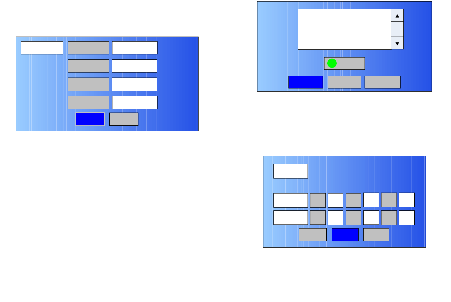
Routine Operation 3-18MTX5000 User and Technical Manual
When the Network Config screen Radio Network option button
is selected, the Radio Network screen is displayed. See
Figure 3-18.
Figure 3-18: Radio Network Screen - Typical
Selection of the Radio IP, Subnet Mask, Gateway, and DNS
Server option buttons allows you to change the network
addresses required to operate your MTX5000 System from a
remote location. Any changes to your network addresses
must be coordinated with your Network Administrator.
Calibration Option Button When the Setup screen
Calibration option button is selected, the PA Voltage Adjust
Setup screen will be displayed. See Figure 3-19.
The PA Voltage Adjust Setup screen provides you with the ability
to calibrate the PA DC power for individual ODUs (RF Units), as
applicable to the options contained in your MTX5000 system, by
selecting the Start option button. The Factory option button is
password-protected for factory use only.
Radio Network IP Address
Back
10.4.3.213
Subnet Mask
Gateway
DNS Server
255.255.0.0
10.4.1.1
10.4.1.21
Main
Figure 3-19: PA Voltage Adjust Setup Screen
Time & Date Option Button When the Date & Time option
button is selected, the Time/Date screen is displayed. See
Figure 3-20. This screen allows you to set the current time and
date.
Figure 3-20: Date & Time Screen - Typical
Level Adjust Option Button When the Setup screen Level
Adjust option button is selected, the RF Output Level Adjust
screen will be displayed. See Figure 3-21 on page 3-19.
<-Previous
Start
Factory->
This process will allow you to calibrate
the PA DC voltage for each specific
frequency band. Once you have the
Radio connected to the ODU
and are ready to start calibration,
Press the START Button below
Main
Time / Date
Submit Cancel
Date
Time Hour
Year
8
2009
Min.
Month
30
3
Sec.
Day
30
17
Tue – Mar 17, 2009 – 08:30:30
Main
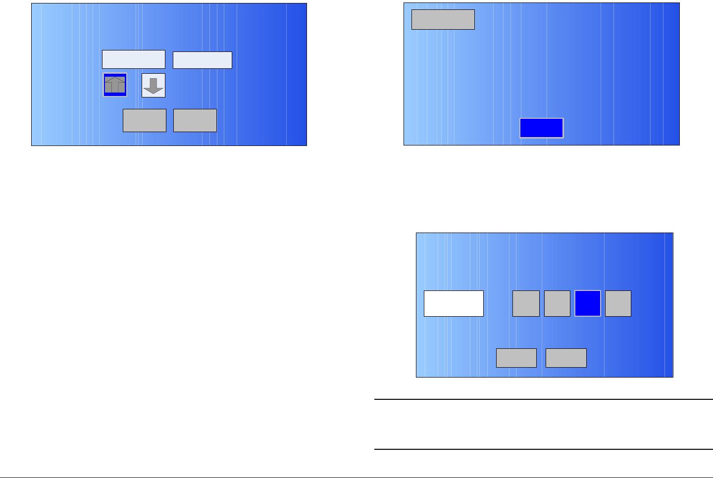
Routine Operation 3-19MTX5000 User and Technical Manual
Figure 3-21: RF Output Level Adjust Screen
The RF Output Level Adjust screen is used to adjust the RF
power output level, as applicable to the options contained in your
MTX5000 system.
The Attenuation level and the resulting Output Power level are
adjusted by selecting the Attenuation Up or Down arrow option
keys, as required, using either the touch screen or function keys
and SEL key to toggle through the Attenuation level options.
License Key Option Button The License Key option button
allows you to add optional factory licensed options to your
MTX5000 IDU without having to return your IDU to the factory for
upgrade. This option button should only be used by the
technical staff.
In order to add a licensed option to your MTX5000 IDU, you
must purchase the license key applicable to the option
required. This license key is available only from MRC.
For information on adding licensed features to your MTX5000
IDU, see ”License Manager” on page 5-117.
Diagnostics Option Button This option is provided to assist in
troubleshooting the IDU. See Figure 3-22.
Back
RF Output Level Adjust
Attenuation Output Power
Auto 40.0 dBm
Main
Figure 3-22: Diagnostics Screen - Typical
Color Bars Option Button When the Color Bars option button
is selected, the Color Bars screen will be displayed. See
Figure 3-23.
Figure 3-23: Color Bars Screen
Note A digital color bar generator is contained in each
MTX5000 IDU. An optional analog color bar
generator is also available.
Diagnostics
Back
IDU +24V +26.41V
IDU +12V +13.12V
IDU -12V -13.20V
IDU +5.5V +5.3V
IDU Fan monitor 329.28mA
IDU Temperature +0.00oC
Color Bars A GenOnOff A Stby
Back Main

Routine Operation 3-20MTX5000 User and Technical Manual
The Color Bar Generator (CBG) has four operating modes that
may be selected as follows:
•Off - Color bars and audio test tones are turned off.
•On - Color bars and audio test tones are continuously
turned on. This mode should be used for test or
troubleshooting only.
•A Gen (Auto Generated) - If a loss of video signal occurs,
color bars and/or audio test tones are transmitted after a
specified delay.
•A Stby (Auto Standby) - If a loss of video signal occurs,
the transmitter is automatically placed into standby (PA is
turned off).
Change Pwd Option Button The Change Pwd option button
provides the means to change the system password. This option
button should only be used by the technical staff.
For information on changing the system password, see ”Local
Mode Password Control” on page 5-3.
System Info Option Button When the System Info option
button is selected, the System Info screen will be displayed.
See Figure 3-24.
The System Info screen will display the current software
versions contained in the MTX5000 IDU.
Figure 3-24: System Info Screen - Typical
3.5 Select Local/Remote Operation
Mode
CAUTION Avoid damage to the color LCD display
panel!
The color LCD display panel touch screen
may be damaged if a sharp, hard-pointed
object, such as a pencil or a pen, is used to
select the displayed options.
Touch screen options must only be selected
using your fingers, a soft-pointed stylus, or
the front panel function keys.
Damage to the color LCD display panel
caused by using a hard-pointed object or
other misuse may void your warranty on
the MTX5000 IDU.
System Info
Back
MTX5000 Control Software V.00.04.XX
Serial #: XXXXX_XX
Date of Manufacture: 03.17.09
System Type Type 11
2.0.0 Analog Software 2.0.1
SCM Software 3.0.1
MPEG Software
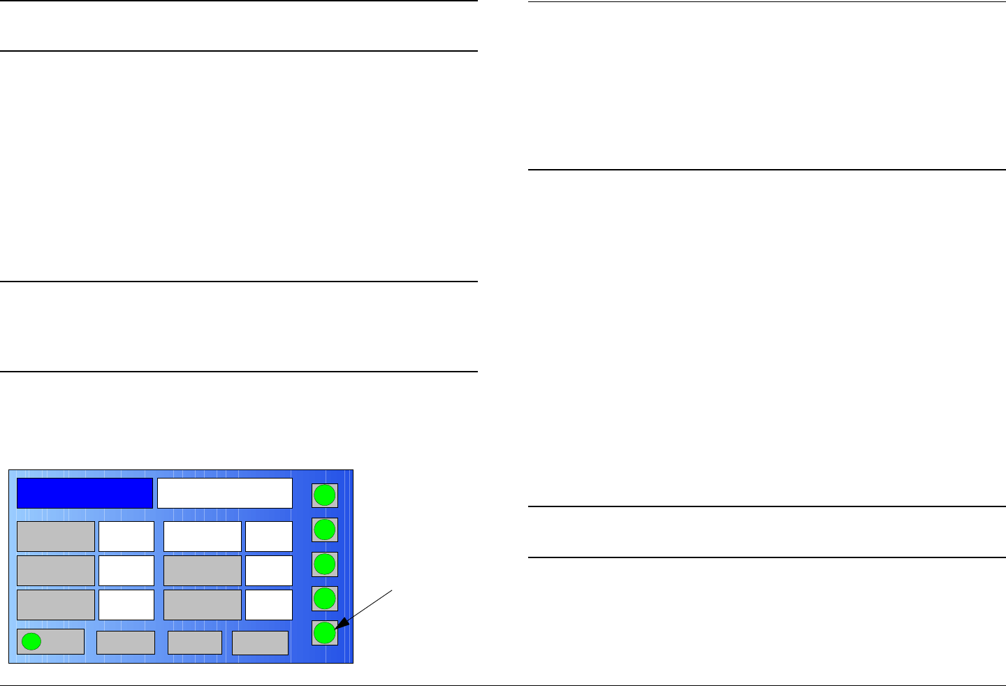
Routine Operation 3-21MTX5000 User and Technical Manual
Note Remote operations must performed using
Internet Explorer 7.0 or later.
The procedure required to select the local or remote operation
mode is contained in the following steps. In order to operate the
MTX5000 remotely, you must connect the MTX5000 to a PC via
your web browser.
In order to operate the MTX5000 via remote control using the
optional Remote Access Subnotebook PC, refer the Remote
Access Subnotebook PC Operator’s Guide, part no. 400573-1.
Selection of the local/remote operation modes can only be
performed at the MTX5000.
Note When performing steps at the MTX5000 in the
following steps, option buttons may be selected
using either the touch screen or the function keys
and the SEL key.
1. Observe the Main screen is displayed. See Figure 3-
25.
Figure 3-25: Main Screen - Typical
Channel 1 0Offset
Antenna Ant. Pol.Antenna1 V
RFU2
7US
RF Band
Preset A Analog
4.83 & 5.8, 3MHz Vid Dev
RF Output XX
dBm
<- Status Setup Status ->
PA On
SUM
ODU
IDU
RF
L/R
H
L
Local/
Remote
(L/R)
Option
Button
Note To select the local operation mode when the
MTX5000 is in the remote mode, perform step 2
and step 3.
To select the remote operation mode when the
MTX5000 is in the local mode and you do not know
the MTX5000 IP address, go to step 4. If you know
the IP address, go to step 9.
2. Observe the L/R option button label indicates R.
3. Select the L/R option button and observe the L/R
option button label changes to L. Procedure is
complete.
4. Select the Setup option button and observe the Setup
screen is displayed.
5. Select the Radio option button and observe the Radio
screen is displayed.
6. Select the Network Config option button and observe
the Network Config screen is displayed.
7. Select the Radio option button and observe the Radio
screen is displayed.
8. Record the IP Address, select the Main option button,
and observe the Main screen is displayed.
Note In the following step, XX.X.X.XXX is the IP address
of your MTX5000 IDU.
9. At the remote PC, open your web browser, enter the IP
address for your MTX5000, and press the PC
keyboard Enter key. The IP address should be
entered as follows:
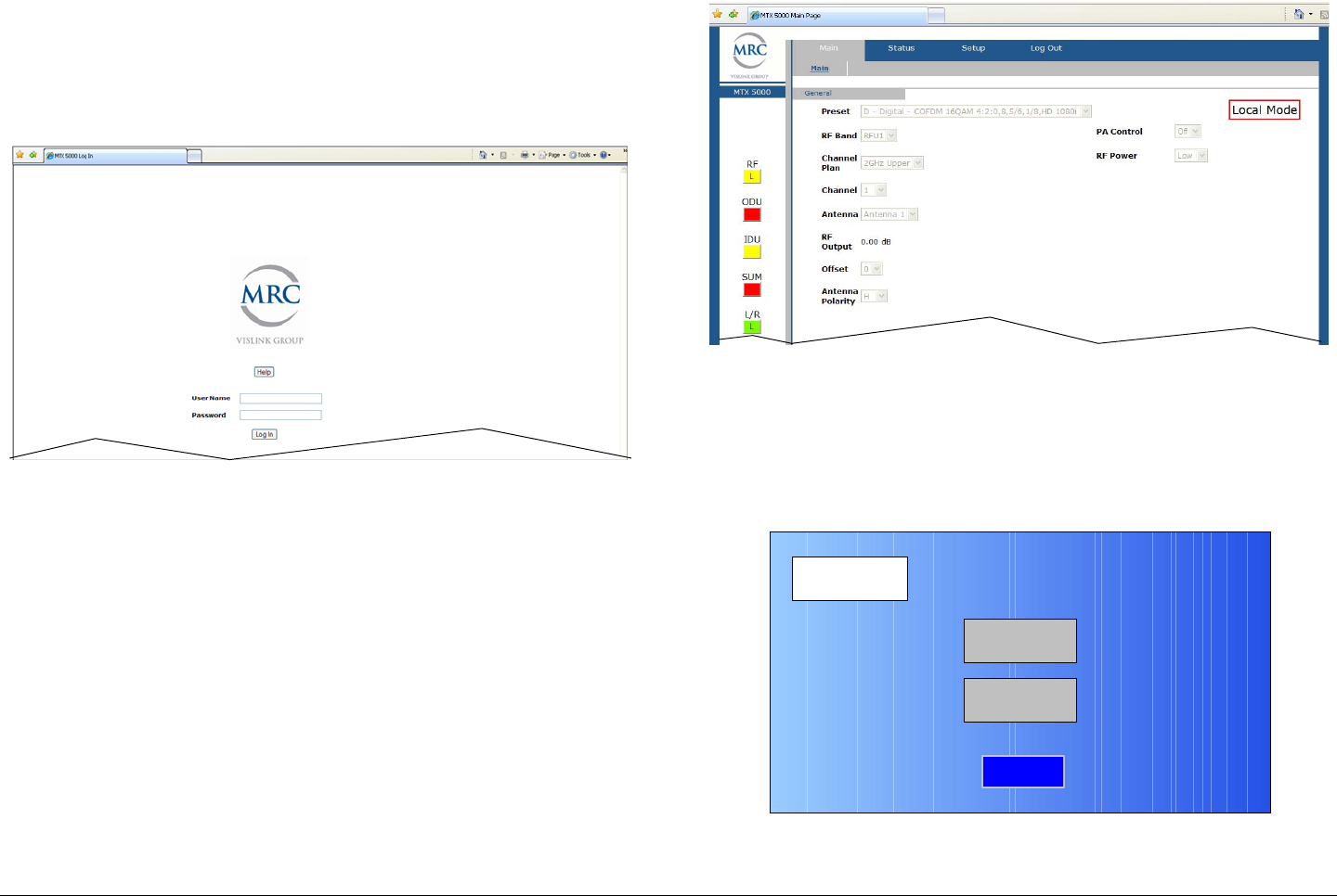
Routine Operation 3-22MTX5000 User and Technical Manual
http://XX.X.X.XXX/nfs/main.html
10. After a short delay, observe the remote log in screen is
displayed. See Figure 3-26.
Figure 3-26: Remote Log In Screen - Typical
11. Enter your user name in the User Name text box,
enter your password in the Password text box, select
the Log In option button, and observe the MTX5000
Main Page is displayed. See Figure 3-27.
Figure 3-27: MTX5000 Main Page - Typical
12. At the MTX5000, verify the L/R option button indicates
L.
13. Select the Setup option button and observe the Setup
screen is displayed. See Figure 3-28.
Figure 3-28: Setup Screen
14. Select the Radio tab and observe the Radio screen is
displayed. See Figure 3-29 on page 3-23.
Setup
User
Main
Radio
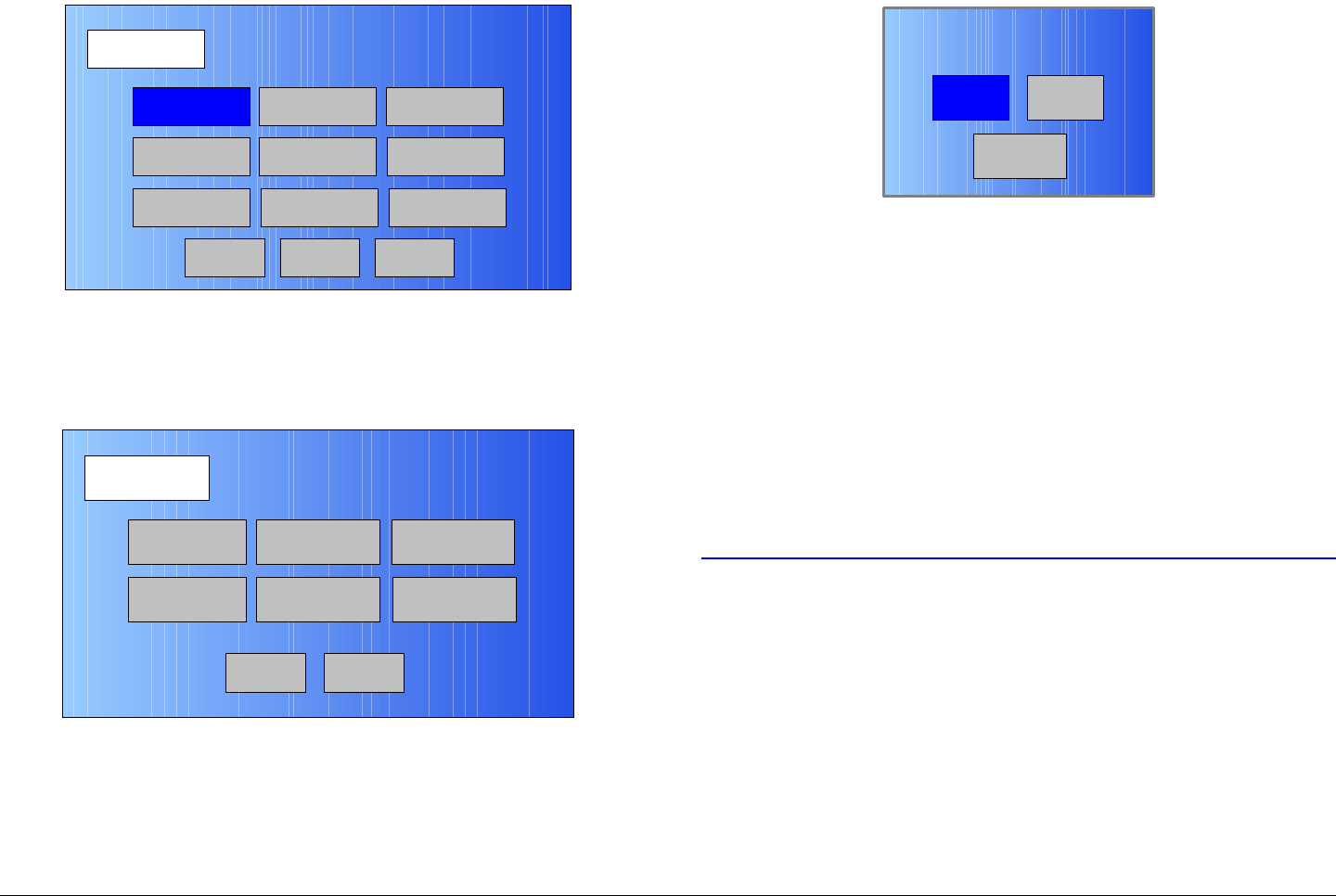
Routine Operation 3-23MTX5000 User and Technical Manual
Figure 3-29: Radio Screen
15. Select the Next tab and observe the Radio - 2 screen
is displayed. See Figure 3-30.
Figure 3-30: Radio - 2 Screen
16. Select the Remote Ctrl Option option button and
observe the Select Remote Ctrl Opt screen is
displayed. See Figure 3-31.
Radio
Back
Network Config Level Adjust Color Bars
Calibration
Time & Date
Change Pwd
System Info
License Key
Diagnostics
Next
Main
Radio - 2
Back
Presets Option
Load Presets
from File
Remote Ctrl
Option
Save Presets
to File
PA State
Option
Restore Presets
to Defaults
Main
Figure 3-31: Select Remote Ctrl Opt Screen
17. Select the Remote option button and observe the
Radio - 2 screen is displayed.
18. Select the Main option button and observe the Main
screen is displayed.
19. Observe the L/R status button label indicates R and
the option button status indicator is amber.
20. Observe the Local Mode status indicator disappears
from the remote screen PC display.
3.6 MTX5000 Local Operations
CAUTION Avoid damage to the color LCD display
panel when performing the following
procedures!
The color LCD display panel touch screen
may be damaged if a sharp, hard-pointed
object, such as a pencil or a pen, is used to
select the displayed options.
Touch screen options must only be selected
using your fingers, a soft-pointed stylus, or
the front panel function keys.
RemoteLocal
Back
Select Remote Ctrl Opt
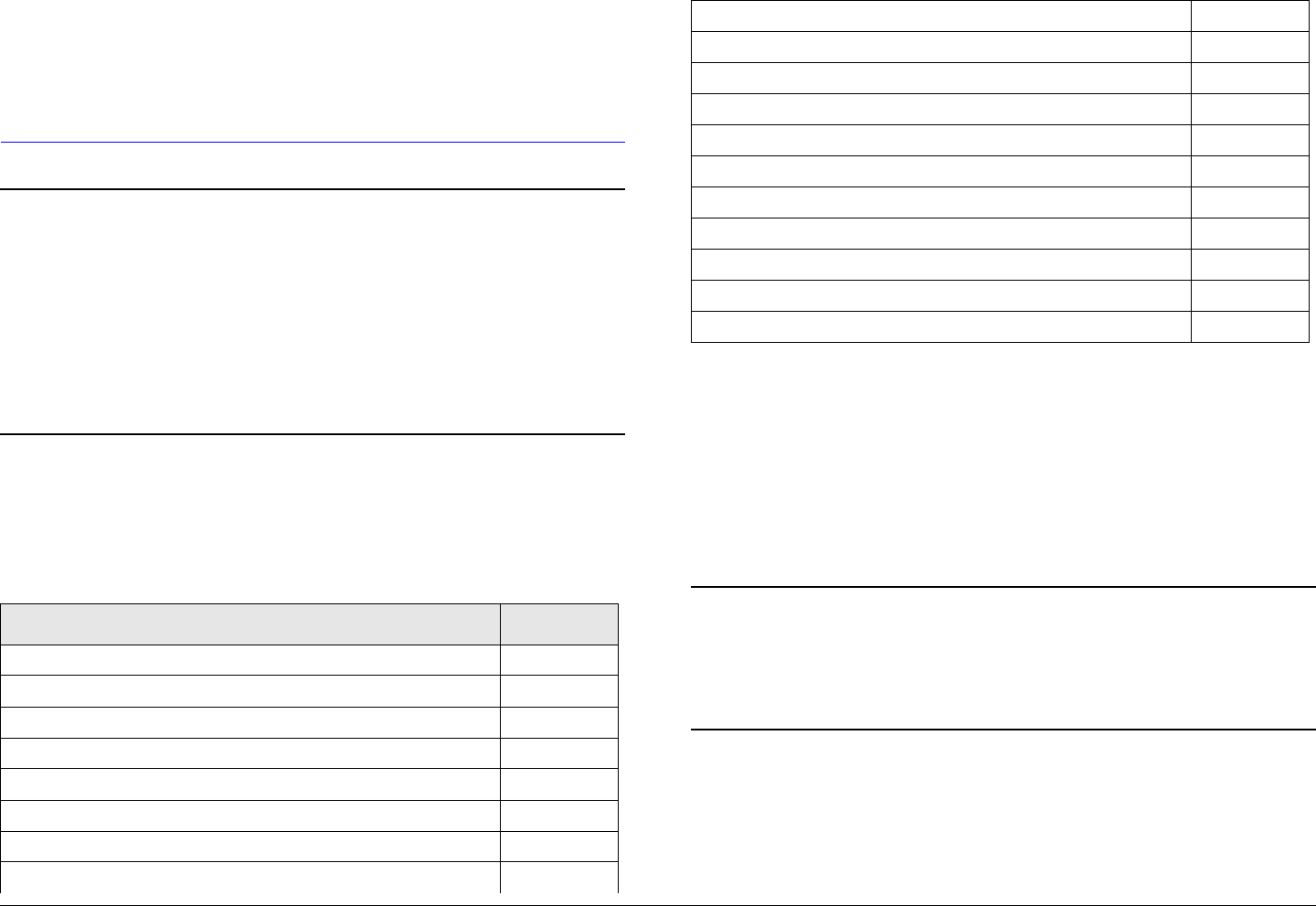
Routine Operation 3-24MTX5000 User and Technical Manual
Damage to the color LCD display panel
caused by using a hard-pointed object or
other misuse may void your warranty on
the MTX5000 IDU.
Note If you are connected to the Ethernet via the IDU
rear panel ETHERNET RJ45 connector and you
find that the color LCD display panel appears to be
operating very slowly or has locked up completely,
disconnect the Ethernet cable from the
ETHERNET connector.
This should free up the color LCD display Panel
and the IDU should resume proper operation.
Once the MTX5000 is powered up, you will be able to check its
configuration and monitor and control its operation in the local
operating mode.
The procedures required to use the Main and Status screens in
the local operating mode are as follows:
Topic Page
Select Preset 3-24
Select RF Band 3-27
Select/Customize Operating Channels 3-30
Select Channel Offset 3-32
Select Antenna 3-33
Select Antenna Polarization 3-34
Enable/Disable Transmitter 3-35
Select High/Low Power Mode 3-36
3.6.1 Select Preset
During performance of this procedure, you may select from a list
of factory Default Presets or from a list of custom User Presets.
Factory Default Presets are identified alphabetically from Preset
A thru Preset J. Custom User Presets are identified numerically
from Preset 1 thru Preset XX, with “XX” being the last Preset
available.
Notes If selecting factory Default Presets in the following
steps, Preset J is not currently active.
Preset F and I are active only if your MTX5000 IDU
contains the applicable licensed factory options.
The procedure required to select a different Preset is contained
in the following steps. You can select a different Preset from a
list of factory-configured Presets and multiple custom Presets.
When performing the following steps, a Main option button to
Monitor ODU Status 3-36
Monitor IDU Status 3-37
Monitor SUM Errors 3-38
Monitor Current Preset Status Settings 3-38
Perform PA Voltage Adjust Setup 3-44
Perform RF Level Adjust 3-49
Select Color Bar Generator Mode 3-52
Set Time and Date 3-54
Perform IDU Diagnostics 3-56
Review System Information 3-57
Set Last PA State 3-58
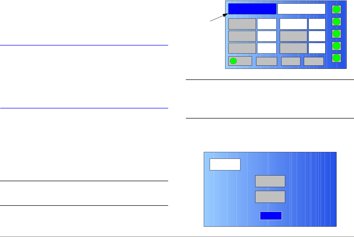
Routine Operation 3-25MTX5000 User and Technical Manual
return you to the Main screen will be displayed at the bottom of
the Preset screen.
If the MTX5000 IDU is transmitting when a Preset is selected,
the PA operation button will become greyed out, indicating the
system is no longer transmitting. The PA operation button must
then be selected to resume transmitting.
CAUTION If you select the wrong Preset in the
following steps, wait a minimum of 5
seconds before attempting to select another
Preset.
Failure to wait a minimum of 5 seconds
between selection of Presets may cause
unstable operation.
When a Preset is selected, the Main screen will be displayed
after a short delay, the Preset on the Main screen will be updated
to display the selected Preset, and the updated system settings
and status of the selected Preset will be displayed.
If the Main option button is selected to return to the Main screen
without selecting a different Preset, the Main screen will be
displayed and no changes will be made to the current MTX5000
settings.
Note In the following steps, option buttons may be
selected using either the touch screen or the
function keys and the SEL key.
1. Observe the Main screen is displayed. See Figure 3-
32.
Figure 3-32: Main Screen - Typical
Note To switch between factory Default or custom User
defaults, go to step 2.
If you do not need to switch between factory
Default or custom User defaults, go to step 8.
2. Select the Setup option button and observe the Setup
screen is displayed. See Figure 3-33.
Figure 3-33: Setup Screen
Channel 1 0Offset
Antenna Ant. Pol.Antenna1 V
RFU2
7US
RF Band
Preset A Analog
4.83 & 5.8, 3MHz Vid Dev
RF Output XX
dBm
<- Status Setup Status ->
PA On
SUM
ODU
IDU
RF
L/R
H
L
Preset X
Option
Button
Setup
User
Main
Radio
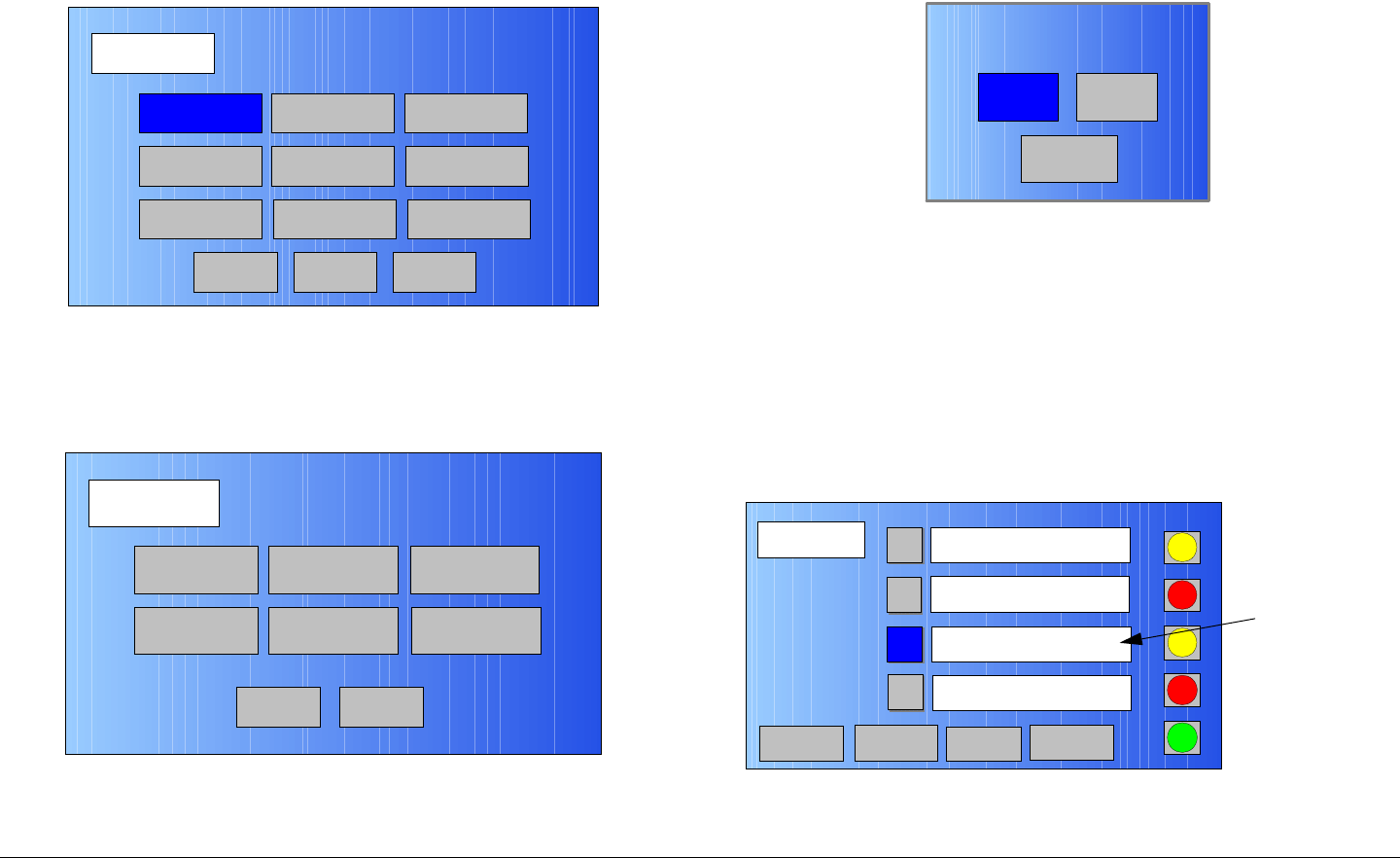
Routine Operation 3-26MTX5000 User and Technical Manual
3. Select the Radio tab and observe the Radio screen is
displayed. See Figure 3-34.
Figure 3-34: Radio Screen
4. Select the Next tab and observe the Radio - 2 screen
is displayed. See Figure 3-35.
Figure 3-35: Radio - 2 Screen
5. Select the Presets Option option button and observe
Radio
Back
Network Config Level Adjust Color Bars
Calibration
Time & Date
Change Pwd
System Info
License Key
Diagnostics
Next
Main
Radio - 2
Back
Presets Option
Load Presets
from File
Remote Ctrl
Option
Save Presets
to File
PA State
Option
Restore Presets
to Defaults
Main
the Select Preset Option screen is displayed. See
Figure 3-36.
Figure 3-36: Select Preset Option Screen
6. Select the Default or User option button, as required,
and observe the Radio - 2 screen is displayed.
7. Select the Main option button and observe the Main
screen is displayed.
8. Select the Main screen Preset X option button and
observe the Presets screen is displayed. See
Figure 3-37.
Figure 3-37: Preset X Screen - Typical
UserDefault
Back
Select Preset Option
Presets
SUM
ODU
IDU
RF
L/R
L
Main
PA Off
A Analog
4.83 & 5.8, 3MHz Vid Dev
D
C
B
L
Analog
4.83 & 6.2, 4MHz Vid Dev
Digital – COFDM 16 QAM
4:2:0,8,5/6,1/8,HD 1080i
Digital – COFDM QPSK
4:2:0,8,1/2,1/8,comp
<- Previous Next ->
Preset
Description
Text Box -
Typical
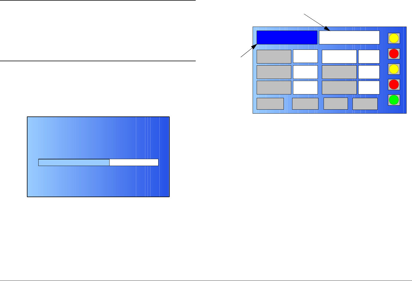
Routine Operation 3-27MTX5000 User and Technical Manual
Note If you decide not to select a different Preset in the
following step and select the Main option button
instead, no configuration changes will be made,
the RECONFIGURING RADIO screen will not be
displayed, the Main screen will be displayed, and
no changes will be displayed in the Preset
description box.
9. Use the Previous and Next option buttons, as
required, select the required Preset option button, and
observe the RECONFIGURING RADIO screen is
displayed. See Figure 3-38.
Figure 3-38: RECONFIGURING RADIO Screen - Typical
10. After a short delay, observe the Main screen is
displayed and observe the new Preset and status data
applicable to the Preset is displayed. See Figure 3-39.
60 %
RECONFIGURING RADIO. PLEASE WAIT!
DO NOT POWER OFF RADIO UNTIL RECONFIGURED!
Figure 3-39: Main Screen - Typical
11. Select the PA operation button to resume transmitting,
as required.
3.6.2 Select RF Band
The procedure required to select an RF band ODU is contained
in the following steps.
If your MTX5000 system is a dual band configuration containing
both a 2 GHz and a 7 GHz ODU (RF head), the procedure
required to select the RF head required for either 2 GHz or
7 GHz operation is contained in the following steps. This
procedure is also used to select either the 2 GHz, 17 MHz
channel plan or the 2 GHz, 12 MHz channel plan, as required for
2 GHz operation.
In a dual band configuration, the 2 GHz RF head is typically
connected to the IDU RFU 1 rear panel connector and the 7 GHz
RF head is typically connected to the RFU 2 rear panel
connector. The RF heads may, however, be connected to either
Channel 1 0Offset
Antenna Ant. Pol.Antenna1 H
RFU2
7US
RF Band
Preset E Digital - COFDM QPSK,
8, 3/4, 1/8, ASI
RF Output XX
dBm
<- Status Setup Status ->
PA Off
SUM
ODU
IDU
RF
L/R
L
L
Preset
Option
Button
Preset Description
Text Box

Routine Operation 3-28MTX5000 User and Technical Manual
rear panel connector. The MTX5000 software automatically
detects the 2 GHz and 7 GHz RF heads and assigns RFU1 and
RFU2 to the respective RF heads on the RF Band screen, as
required.
If your MTX5000 system is a single 2 GHz or 7 GHz
configuration, the RF head may be connected to either the IDU
RFU 1 or RFU 2 rear panel connector. The MTX5000 software
automatically detects the RF head configuration and connection
and assigns RFU1 or RFU2 to the RF head on the RF Band
screen, as applicable.
When performing the following steps, a navigation option button
to return you to the Main screen will be displayed at the bottom
of the RF Band screen.
When the new RF head is selected, the updated system status
associated with the RF Band option button will display the new
selected RF head, after a short delay. The Main option button
must then be selected to return to the Main screen.
If the Main option button is selected to return to the Main screen
without selecting a new RF head, the Main screen will be
displayed and no changes will be made to current MTX5000
settings.
Note In the following steps, option buttons may be
selected using either the touch screen or the
function keys and the SEL key.
1. Observe the Main screen is displayed. See Figure 3-
40.
Figure 3-40: Main Screen - Typical
2. Select the RF Band option button and observe the RF
Band screen is displayed and the current RF band
option button is highlighted. See Figure 3-41,
Figure 3-42 on page 3-29, Figure 3-43 on page 3-29,
or Figure 3-44 on page 3-29.
Figure 3-41: RF Band 2 GHz RFU1 Option Screen
Channel 1 0Offset
Antenna Ant. Pol.Antenna1 V
RFU2
7US
RF Band
Preset A Analog
4.83 & 5.8, 3MHz Vid Dev
RF Output XX
dBm
<- Status Setup Status ->
PA On
SUM
ODU
IDU
RF
L/R
H
L
RF
Band
Option
Button
2GHz Change Plan
RFU2
RFU1
RF Band
Main
PA On
SUM
ODU
IDU
RF
L/R
H
L
Main Screen
Option Button
RF Band
Option
Buttons
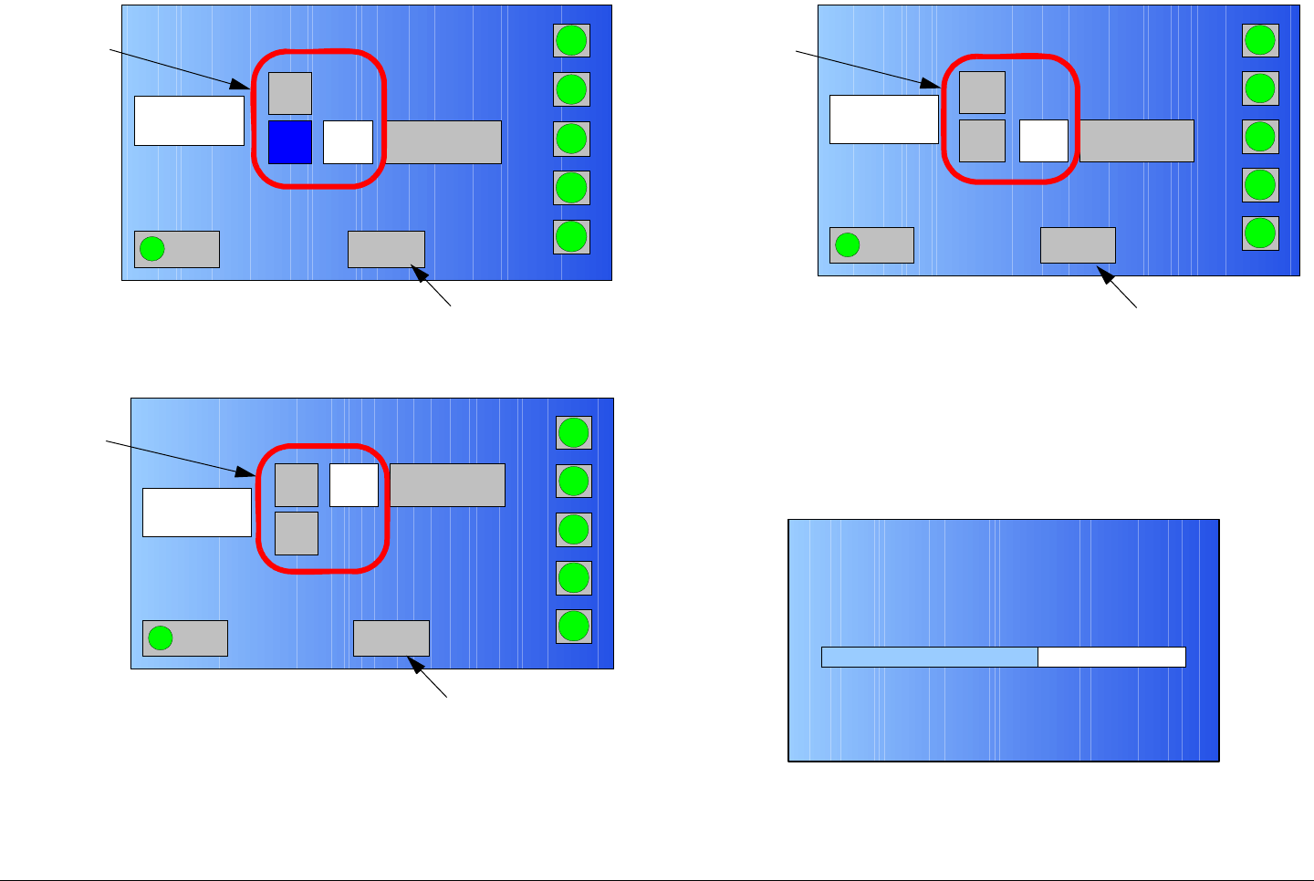
Routine Operation 3-29MTX5000 User and Technical Manual
Figure 3-42: RF Band 2 GHz RFU2 Option Screen
Figure 3-43: RF Band 7 GHz RFU1 Option Screen
RFU2
RFU1
RF Band
Main
PA On
SUM
RF
IDU
RF
L/R
H
L
2GHz Change Plan
Main Screen
Option Button
RF Band
Option
Buttons
RFU2
RFU1
RF Band
Main
PA On
SUM
ODU
IDU
RF
SUM
H
L
7GHz Change Plan
Main Screen
Option Button
RF Band
Option
Buttons
Figure 3-44: RF Band 7 GHz RFU2 Option Screen
3. Select the RFU1 or RFU2 2 GHz or 7 GHz RF head
option button, as required, and observe the
RECONFIGURING RADIO screen is displayed. See
Figure 3-45.
Figure 3-45: RECONFIGURING RADIO Screen - Typical
RFU2
RFU1
RF Band
Main
PA On
SUM
ODU
IDU
RF
L/R
H
L
2GHz Change Plan
Main Screen
Option Button
RF Band
Option
Buttons
60 %
RECONFIGURING RADIO. PLEASE WAIT!
DO NOT POWER OFF RADIO UNTIL RECONFIGURED!
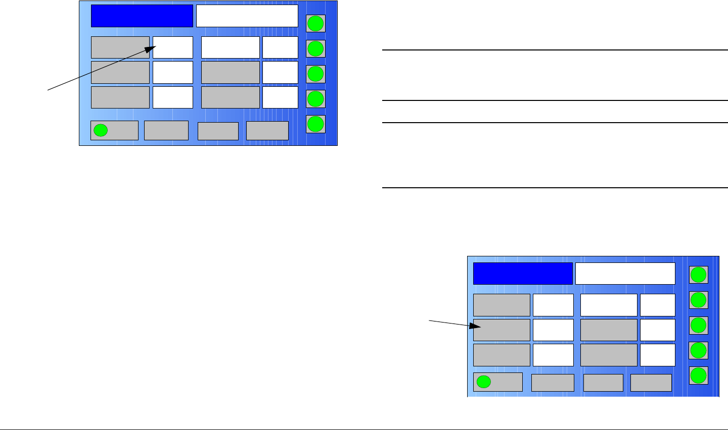
Routine Operation 3-30MTX5000 User and Technical Manual
4. After a short delay, observe the new RF Band is active
(blue), select the Main option button, and observe the
new RF band setting is displayed. See Figure 3-46.
Figure 3-46: Main Screen - Typical
5. To select a new operating channel, perform “Select/
Customize Operating Channels”, as required.
3.6.3 Select/Customize Operating Channels
The procedure required to select an operating channel or to
prepare a customized channel is contained in the following
steps.
When performing the following steps, a navigation option button
to return you to the Main screen will be displayed at the bottom
of the Channel screen.
When the new channel options are selected, the Main screen will
be displayed and the updated system status associated with the
Channel option button will display the newly selected channel.
When a channel is customized, the channel number that was
changed will not automatically be displayed on the Main page
unless that channel was already selected. If a channel is
Channel 1 0Offset
Antenna Ant. Pol.Antenna1 V
RFU1
2G17M
RF Band
Preset A Analog
4.83 & 5.8, 3MHz Vid Dev
RF Output XX
dBm
<- Status Setup Status ->
PA On
SUM
ODU
IDU
RF
L/R
H
L
New RF
Band
Setting
customized that was not selected on the Main page, the
customized channel number must be selected from the Main
page using the Channel option button and the Channel screen.
If the Main option button is selected to return to the Main screen
without selecting a new channel, the Main screen will be
displayed and no changes will be made to current MTX5000
settings.
Note In the following steps, option buttons may be
selected using either the touch screen or the
function keys and the SEL key.
Note To select the operating channel only, perform step
1 thru step 3.
To customize individual channels, go to step 4.
1. Observe the Main screen is displayed. See Figure 3-
47.
Figure 3-47: Main Screen - Typical
Channel 1 0Offset
Antenna Ant. Pol.Antenna1 V
RFU2
7US
RF Band
Preset A Analog
4.83 & 5.8, 3MHz Vid Dev
RF Output XX
dBm
<- Status Setup Status ->
PA On
SUM
ODU
IDU
RF
L/R
H
L
Channel
Option
Button
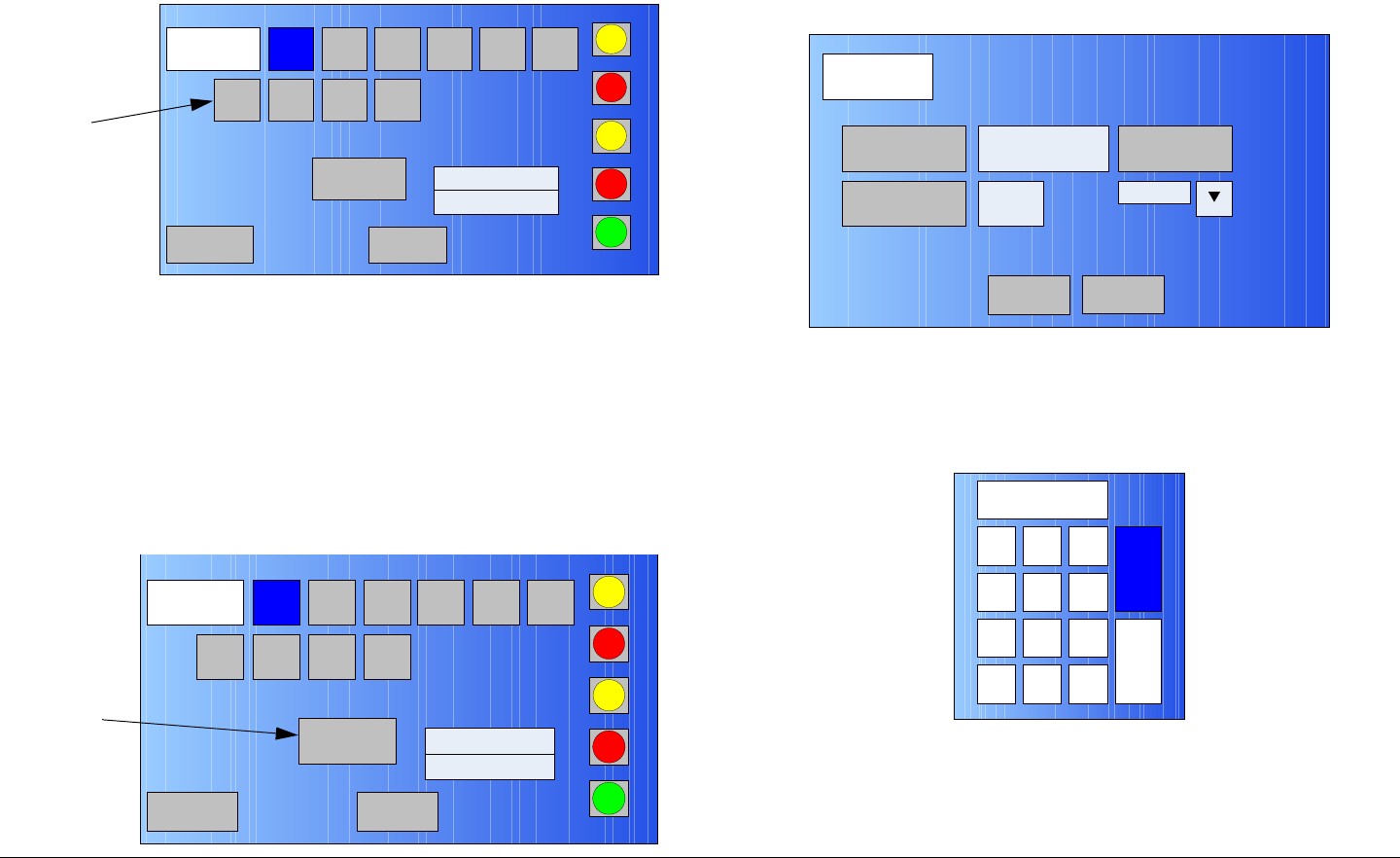
Routine Operation 3-31MTX5000 User and Technical Manual
2. Select the Channel option button and observe the
Channel screen is displayed. See Figure 3-48.
Figure 3-48: Channel Screen - Typical
3. Select the Channel option button required, observe
the Main screen is displayed, and observe the
Channel option has been changed. Procedure is
complete.
4. Select the Main screen Channel option button and
observe the Channel screen is displayed. See
Figure 3-49.
Figure 3-49: Channel Screen - Typical
1
Channel
Main
PA Off
SUM
ODU
IDU
RF
L/R
L
User Def CH 1
1.999000 GHz
L
2 3 4 5 6
7 8 9 10
Channel
Option
Buttons
1
Channel
Main
PA Off
SUM
ODU
IDU
RF
L/R
L
User Def CH 1
1.999000 GHz
L
2 3 4 5 6
78910
User Def
Option
Button
5. Select the User Def option button and observe the
USER CHANNEL screen is displayed. See Figure 3-
50.
Figure 3-50: USER CHANNEL Screen - Typical
6. Select the Frequency option button and observe the
numeric keypad is displayed. See Figure 3-51.
Figure 3-51: Numeric Keypad
7. Enter frequency required, select the ENT option
button, and observe the USER CHANNEL screen is
displayed.
USER
CHANNEL
Frequency
3
2.031500 GHz
Save
Chan. Select
Offset
0
Cancel
1 2 3
ESC
0
4
7
5 6
8 9
DEL 0ESC
ENT
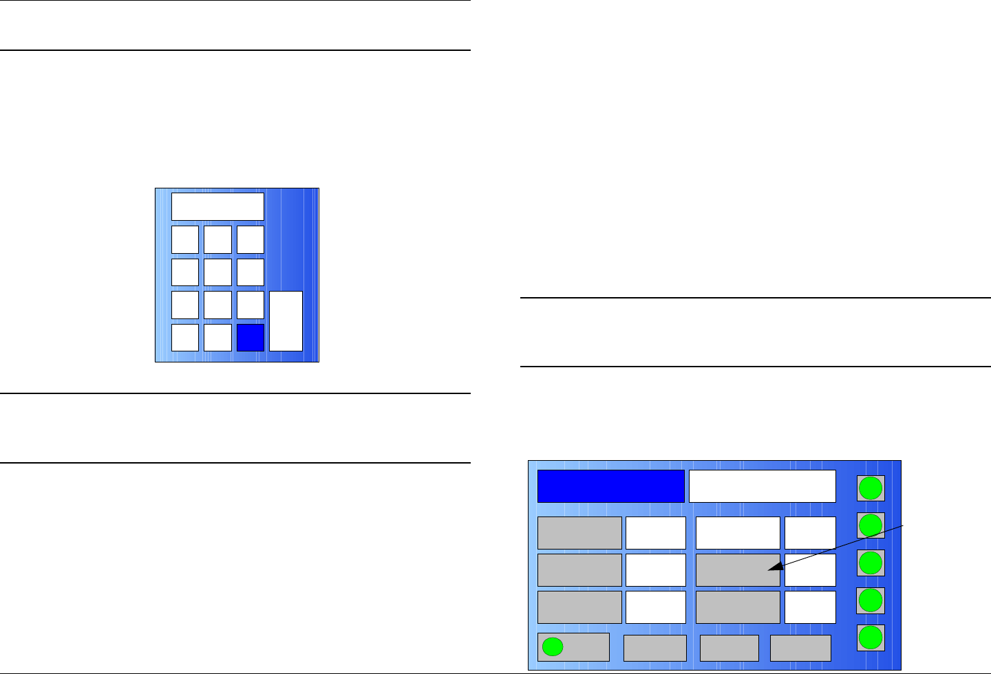
Routine Operation 3-32MTX5000 User and Technical Manual
Note The ++ offset option is not a valid option for 2 GHz
and 7 GHz channel plans.
8. Select the Offset pull-down menu and select -
(minus), 0 (center), or + (plus) offset, as required.
9. Select the Chan. Select option button and observe
the numeric keypad is displayed. See Figure 3-52.
Figure 3-52: Numeric Keypad
Note In the following step, channels 1 thru 10 may be
selected for the 2 GHz band; channels 1 thru 14
may be selected for the 7 GHz band.
10. Enter the channel number required, select the ENT
option button, and observe the USER CHANNEL
screen is displayed.
11. Select the Save option button and observe the
Channel screen is displayed.
12. Select the Main option button and observe the Main
screen is displayed.
123
4
7
5 6
8 9
CLR 0ESC
ENT
3.6.4 Select Channel Offset
The procedure required to select the channel frequency offset is
contained in the following steps.
When performing the following steps, a navigation option button
to return you to the Main screen will be displayed at the bottom
of the Offset screen.
When the new offset is selected, the Main screen will
automatically be displayed and the updated system status
associated with the Offset option button will display the new
offset.
If the Main option button is selected to return to the Main screen
without selecting a new offset, the Main screen will be displayed
and no changes will be made to current MTX5000 settings.
Note In the following steps, option buttons may be
selected using either the touch screen or the
function keys and the SEL key.
1. Observe the Main screen is displayed. See Figure 3-
53.
Figure 3-53: Main Screen - Typical
Channel 1 0Offset
Antenna Ant. Pol.Antenna1 V
RFU2
7US
RF Band
Preset A Analog
4.83 & 5.8, 3MHz Vid Dev
RF Output XX
dBm
<- Status Setup Status ->
PA On
SUM
ODU
IDU
RF
L/R
H
L
Offset
Option
Button
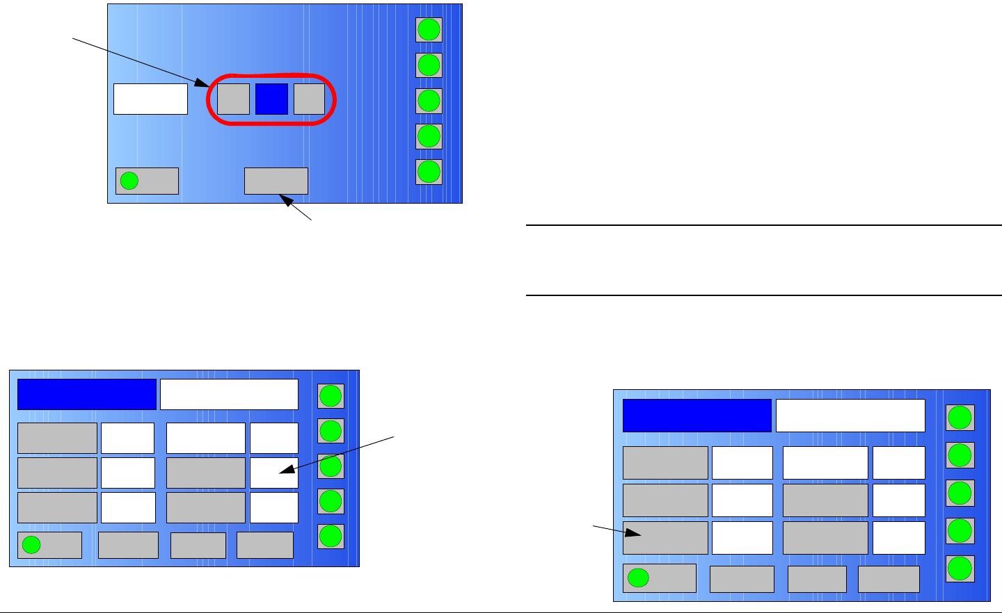
Routine Operation 3-33MTX5000 User and Technical Manual
2. Select the Offset option button and observe the
Offset screen is displayed. See Figure 3-54.
Figure 3-54: Offset Screen - Typical
3. Select the Offset option button required, observe the
Main screen is displayed, and observe the new offset
setting is displayed. See Figure 3-55.
Figure 3-55: Main Screen - Typical
Offset
Main
PA On
SUM
ODU
IDU
RF
L/R
H
-0+
L
Main Screen
Option Button
Offset
Option
Buttons
Channel 1Offset
Antenna Ant. Pol.Antenna1 V
RFU2
7US
RF Band
Preset A Analog
4.83 & 5.8, 3MHz Vid Dev
RF Output XX
dBm
<- Status Setup Status ->
PA On
SUM
ODU
IDU
RF
L/R
H
_
L
New
Offset
Setting
3.6.5 Select Antenna
The procedure required to select a different antenna is contained
in the following steps. When performing the following steps, a
navigation option button to return you to the Main screen will be
displayed at the bottom of the Antenna screen.
When the new antenna is selected, the Main option button must
be selected, the Main screen will automatically be displayed, and
the updated system status associated with the Antenna option
button will display the new selected antenna.
If the Main option button is selected to return to the Main screen
without selecting a different antenna, the Main screen will be
displayed and no changes will be made to current MTX5000
settings.
Note In the following steps, option buttons may be
selected using either the touch screen or the
function keys and the SEL key.
1. Observe the Main screen is displayed. See Figure 3-
56.
Figure 3-56: Main Screen - Typical
Channel 1 0Offset
Antenna Ant. Pol.Antenna1 V
RFU2
7US
RF Band
Preset A Analog
4.83 & 5.8, 3MHz Vid Dev
RF Output XX
dBm
<- Status Setup Status ->
PA On
SUM
ODU
IDU
RF
L/R
H
L
Antenna
Option
Button
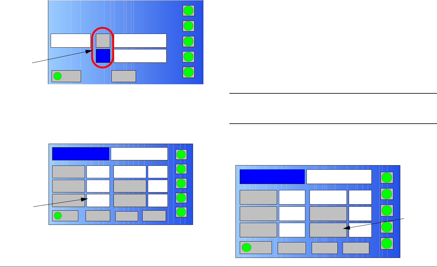
Routine Operation 3-34MTX5000 User and Technical Manual
2. Select the Antenna option button and observe the
Antenna screen is displayed. See Figure 3-57.
Figure 3-57: Antenna Screen - Typical
3. Select the Antenna option button required, select the
Main option button, observe the Main screen is
displayed, and observe the antenna selected is
displayed. See Figure 3-58.
Figure 3-58: Main Screen - Typical
3.6.6 Select Antenna Polarization
The procedure required to select the antenna polarization is
contained in the following steps.
Antenna
Option
Buttons
Antenna
Main PA On
SUM
ODU
IDU
RF
L/R
H
Ant. 1
Ant. 2
Antenna1
Antenna2
L
Channel 2 0Offset
Antenna Ant. Pol.Antenna2 V
RFU2
7US
RF Band
Preset A Analog
4.83 & 5.8, 3MHz Vid Dev
RF Output XX
dBm
<- Status Setup Status ->
PA On
SUM
ODU
IDU
RF
L/R
H
L
New
Antenna
Setting
When performing the following steps, a navigation option button
to return you to the Main screen will be displayed at the bottom
of the Antenna Polarity screen.
When the new antenna polarization is selected, the Main option
button must be selected, the Main screen will be displayed, and
the updated system status associated with the Ant. Pol. option
button will display the new selected antenna polarization. The
options available are H (Horizontal), V (Vertical), RC (Right
Circular), and LC (Left Circular).
If the Main option button is selected to return to the Main screen
without selecting a new antenna polarization setting, the Main
screen will be displayed and no changes will be made to current
MTX5000 settings.
Note In the following steps, option buttons may be
selected using either the touch screen or the
function keys and the SEL key.
1. Observe the Main screen is displayed. See Figure 3-
59.
Figure 3-59: Main Screen - Typical
Channel 1 0Offset
Antenna Ant. Pol.Antenna1 V
RFU2
7US
RF Band
Preset A Analog
4.83 & 5.8, 3MHz Vid Dev
RF Output XX
dBm
<- Status Setup Status ->
PA On
SUM
ODU
IDU
RF
L/R
H
L
Ant.Pol.
Option
Button
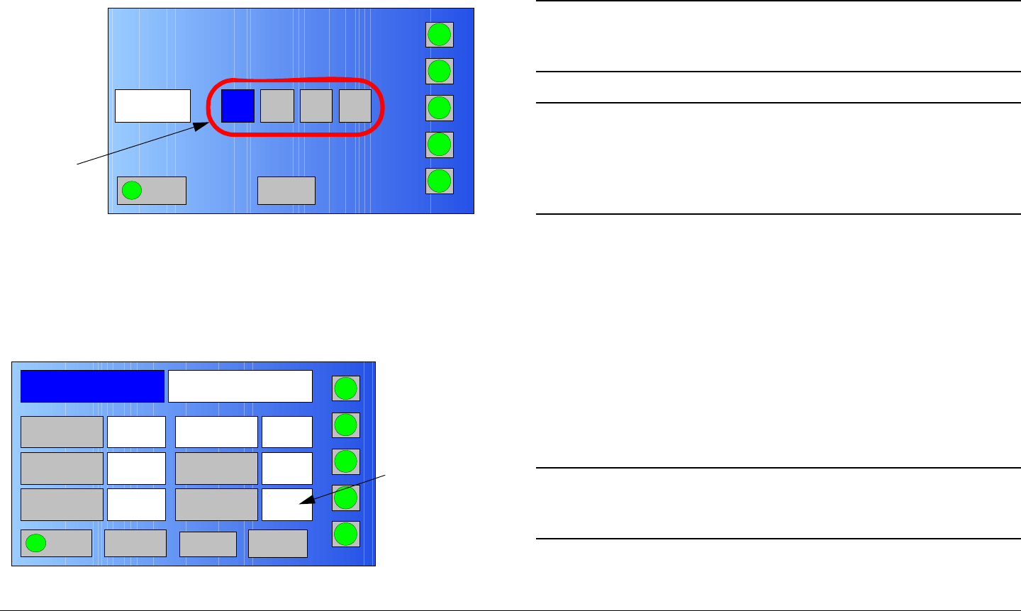
Routine Operation 3-35MTX5000 User and Technical Manual
2. Select the Ant. Pol. option button and observe the
Antenna Polarity screen is displayed. See Figure 3-
60.
Figure 3-60: Antenna Polarity Screen - Typical
3. Select the Antenna Polarity option button required,
select the Main option button, observe the Main
screen is displayed, and observe the new antenna
polarization is displayed. See Figure 3-61.
Figure 3-61: Main Screen - Typical
Antenna
Polarity
Main PA On
SUM
ODU
IDU
RF
L/R
H
HVRC LC
L
Antenna
Polarity
Option
Buttons
Channel 1 0Offset
Antenna Ant. Pol.Antenna1 H
RFU2
7US
RF Band
Preset A Analog
4.83 & 5.8, 3MHz Vid Dev
RF Output XX
dBm
<- Status Setup Status ->
PA On
SUM
ODU
IDU
RF
L/R
H
L
New
Antenna
Polarization
Setting
3.6.7 Enable/Disable Transmitter
The procedure required to enable or disable the transmitter is
contained in the following steps.
Note In the following procedure, the PA option button
may be selected using either the touch screen or
the function keys and the SEL key.
Note The transmitter may be enabled or disabled from
the Main screen or from any screen that is
accessible from the Main screen. The screen
shown in Figure 3-62 on page 3-36 is therefore
typical.
In the following steps, selecting the PA option button will change
the state of the transmitter from enabled to disabled or from
disabled to enabled.
When the transmitter is disabled (not transmitting), the PA option
button will be grey and the label will display PA Off. When the
option button is selected, an orange indicator will initially be
displayed indicating the PA is preparing to transmit and the
option button label will indicate PA.
When the unit begins to transmit, the indicator will change to
green and the option button label will change to PA On.
Note To enable the transmitter, perform step 1 only.
To disable the transmitter, go to step 2.
1. Select the PA operation button, observe the PA option
button becomes active (green) after a short delay, and
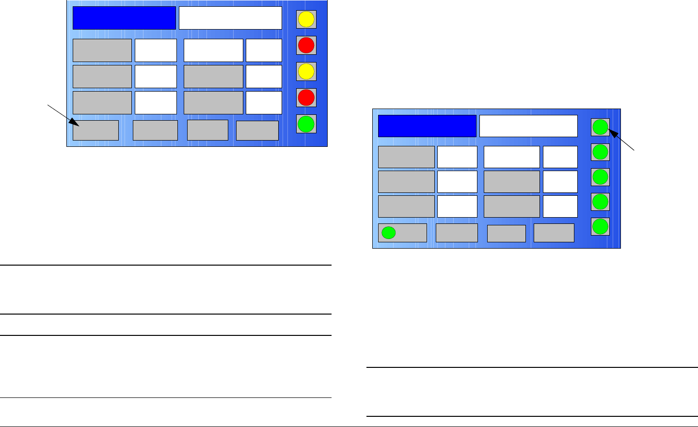
Routine Operation 3-36MTX5000 User and Technical Manual
the option button label changes to read PA On. See
Figure 3-62.
Figure 3-62: Main Screen - Typical
2. Select the PA option button and observe the option
button label changes to PA Off.
3.6.8 Select High/Low Power Mode
The procedure required to select the transmitter high or low
power output mode is contained in the following steps.
Note In the following procedure, the RF option button
may be selected using either the touch screen or
the function keys and the SEL key.
Notes The transmitter output power mode may be
selected from the Main screen or from any screen
that is accessible from the Main screen. The
screen shown in Figure 3-63 is therefore typical.
Channel 1 0Offset
Antenna Ant. Pol.Antenna1 H
RFU1
No RF
RF Band
Preset A Analog
4.83 & 5.8, 3MHz Vid Dev
RF Output XX
dBm
<- Status Setup Status ->
PA Off
SUM
ODU
IDU
RF
L/R
L
L
PA Option
Button
In the following steps, selecting the RF option button will change
the state of the transmitter from low power to high power or from
high power to low power.
When the transmitter is in the low power mode, the RF status
indicator will be yellow and the button label will display L. When
the transmitter is in the high power mode, the RF status indicator
will be green and the button label will display H.
1. Select the RF option button and observe the RF option
button becomes active. See Figure 3-63.
Figure 3-63: Main Screen - Typical
2. Select the RF option button, as required, until the RF
status indicator changes to the required state.
3.6.9 Monitor ODU Status
The procedure required to monitor the current alarm status of the
ODU is contained in the following steps.
Note In the following procedure, the ODU status button
may be selected using either the touch screen or
the function keys and the SEL key.
Channel 1 0Offset
Antenna Ant. Pol.Antenna1 H
RFU2
7US
RF Band
Preset A Analog
4.83 & 5.8, 3MHz Vid Dev
RF Output XX
dBm
<- Status Setup Status ->
PA On
SUM
ODU
IDU
RF
L/R
H
L
RF Option
Button
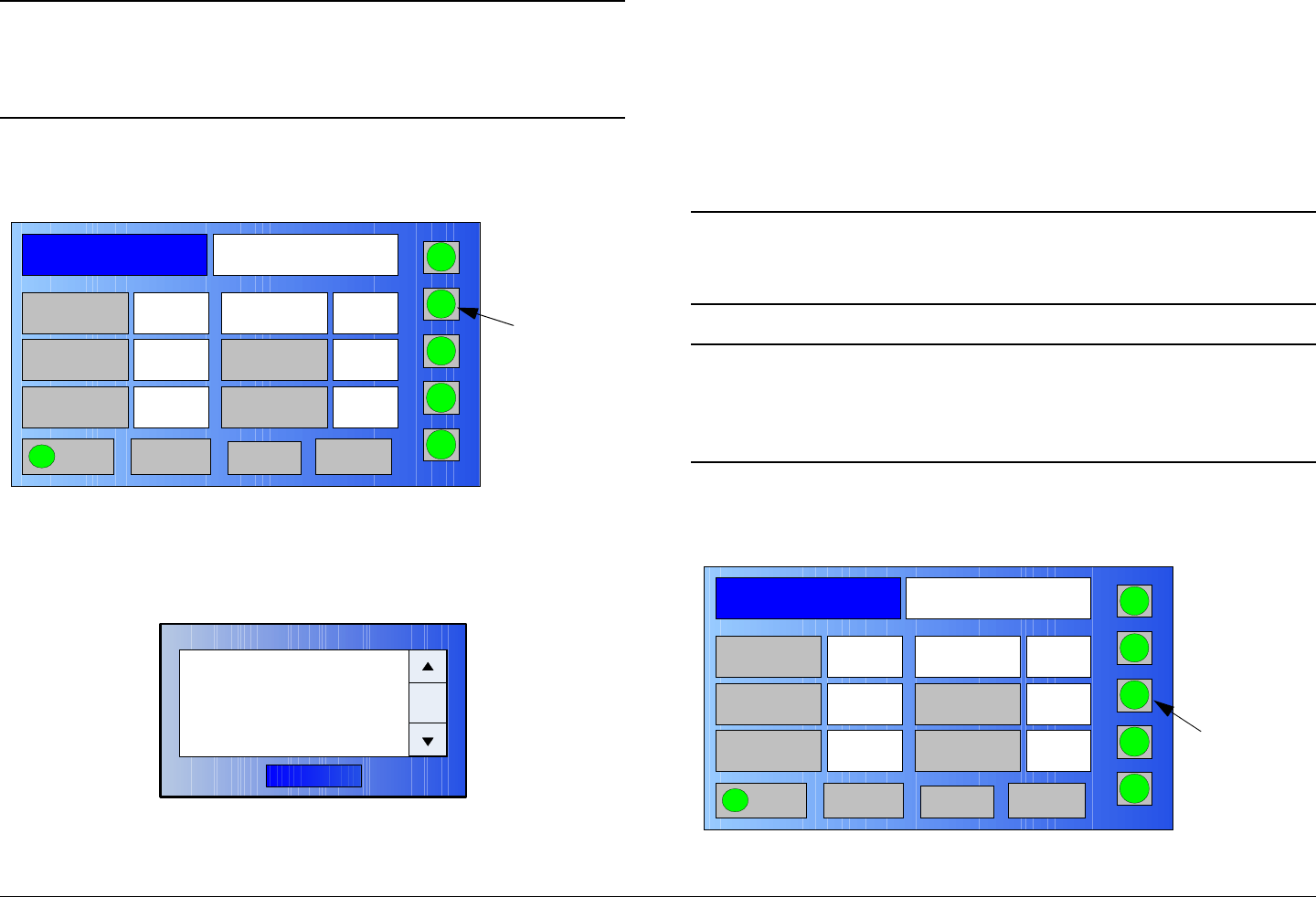
Routine Operation 3-37MTX5000 User and Technical Manual
Note The ODU status button may be selected from the
Main screen or from any screen that is accessible
from the Main screen. The screen shown in
Figure 3-64 is therefore typical.
1. Select the ODU status button. See Figure 3-64.
Figure 3-64: Main Screen - Typical
2. Observe the ODU Status screen is displayed. See
Figure 3-65.
Figure 3-65: ODU Status Dialog Box - Typical
Channel 1 0Offset
Antenna Ant. Pol.Antenna1 H
RFU2
7US
RF Band
Preset A Analog
4.83 & 5.8, 3MHz Vid Dev
RF Output XX
dBm
<- Status Setup Status ->
PA On
SUM
ODU
IDU
RF
L/R
H
L
ODU
Status
Button
OK
ODU Status
xxxxxxxxxxx
3. When review of ODU Status messages is complete,
select the OK option button and observe the ODU
Status screen is no longer displayed.
3.6.10 Monitor IDU Status
The procedure required to monitor the current alarm status of the
IDU is contained in the following steps.
Note In the following procedure, the IDU status button
may be selected using either the touch screen or
the function keys and the SEL key.
Note The IDU status button may be selected from the
Main screen or from any screen that is accessible
from the Main screen. The screen shown in
Figure 1 is therefore typical.
1. Select the IDU status button. See Figure 3-66.
Figure 3-66: Main Screen - Typical
Channel 1 0Offset
Antenna Ant. Pol.Antenna1 H
RFU2
7US
RF Band
Preset A Analog
4.83 & 5.8, 3MHz Vid Dev
RF Output XX
dBm
<- Status Setup Status ->
PA On
SUM
ODU
IDU
RF
L/R
H
L
IDU
Status
Button
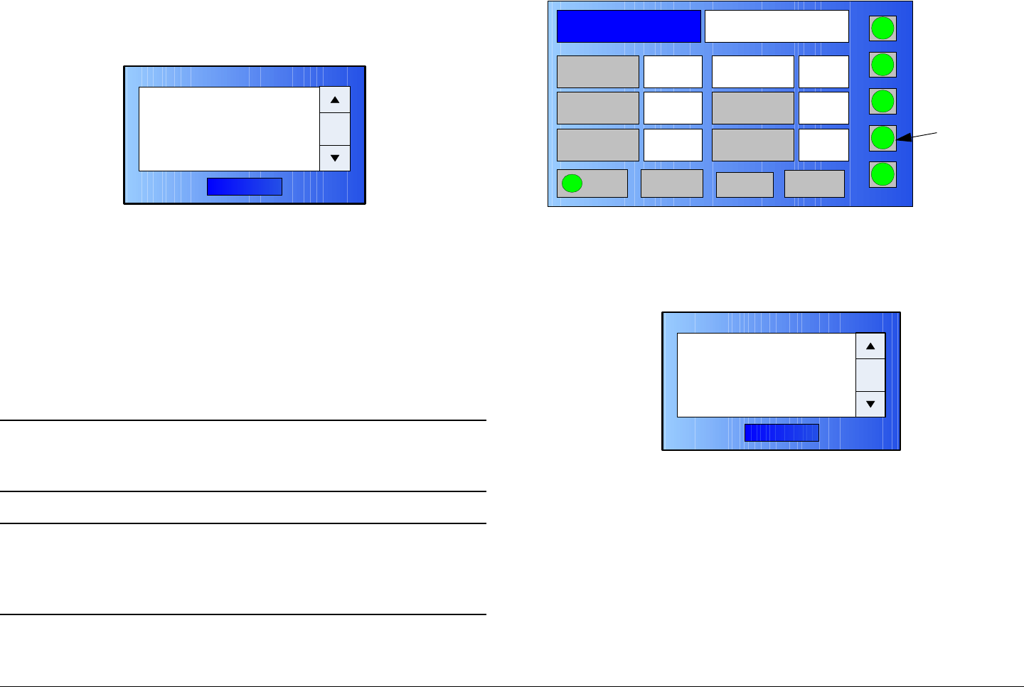
Routine Operation 3-38MTX5000 User and Technical Manual
2. Observe the IDU Status screen is displayed. See
Figure 3-67.
Figure 3-67: IDU Status Dialog Box - Typical
3. When review of IDU Status messages is complete,
select the OK option button and observe the IDU
Status screen is no longer displayed.
3.6.11 Monitor SUM Errors
The procedure required to monitor current summary alarms in
the MTX5000 Transmitter System is contained in the following
steps.
Note In the following procedure, the SUM status button
may be selected using either the touch screen or
the function keys and the SEL key.
Note The SUM status button may be selected from the
Main screen or from any screen that is accessible
from the Main screen. The screen shown in
Figure 3-68 on page 3-38 is therefore typical.
1. Select the SUM status button. See Figure 3-68.
OK
IDU Status
xxxxxxxxxxxxxxxxx
Figure 3-68: Main Screen - Typical
2. Observe the Summary Alarm screen is displayed.
See Figure 3-69.
Figure 3-69: Summary Alarm Dialog Box - Typical
3. When review of Summary Alarm messages is
complete, select the OK option button and observe the
Summary Alarm screen is no longer displayed.
3.6.12 Monitor Current Preset Status Settings
The procedure required to monitor Preset status settings are
contained in the following steps.
Channel 1 0Offset
Antenna Ant. Pol.Antenna1 H
RFU2
7US
RF Band
Preset A Analog
4.83 & 5.8, 3MHz Vid Dev
RF Output XX
dBm
<- Status Setup Status ->
PA On
SUM
ODU
IDU
RF
L/R
H
L
SUM
Status
Button
OK
Summary Alarm
xxxxxxxxxxxxxxxxx
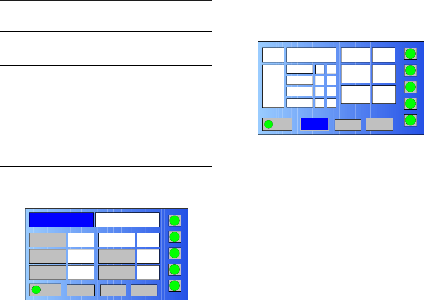
Routine Operation 3-39MTX5000 User and Technical Manual
Note In the following steps, option buttons may be
selected using either the touch screen or the
function keys and the SEL key.
1. Select the Preset to be monitored per “Select Preset”
on page 3-24, as required.
Notes If the Preset to be monitored is an External IF Input
Preset, status settings are not applicable.
If the Preset to be monitored is an analog Preset,
go to step 2.
If the Preset to be monitored is a digital COFDM
ASI Preset, go to step 5.
If the Preset to be monitored is a digital COFDM,
LMS-T, DVB-S, or digital IP Preset, go to step 11.
2. Observe the Main screen is displayed. See Figure 3-
70.
Figure 3-70: Main Screen (Analog Mode) - Typical
Channel 1 0Offset
Antenna Ant. Pol.Antenna1 V
RFU2
7US
RF Band
Preset A Analog
4.83 & 5.8, 3MHz Vid Dev
RF Output XX
dBm
<- Status Setup Status ->
PA On
SUM
ODU
IDU
RF
L/R
H
L
3. Select either Status option button and observe the
selected analog Preset status screen is displayed.
See Figure 3-71.
Figure 3-71: Status Screen (Analog Mode) - Typical
4. When review of the analog Preset Status screen is
complete, select either of the Main option buttons and
observe the Main screen is displayed. Procedure is
complete.
5. Observe the Main screen is displayed. See Figure 3-
72 on page 3-40.
YModulation
Audio
4830 KHz
Video Composite Video
Deviation 3MHz
<- Main Setup Main ->
PA On
SUM
ODU
IDU
RF
L/R
H
On
4830 KHz
4830 KHz
4830 KHz
Y
N
N
On
On
On
RF Out
FM
xx dB
L
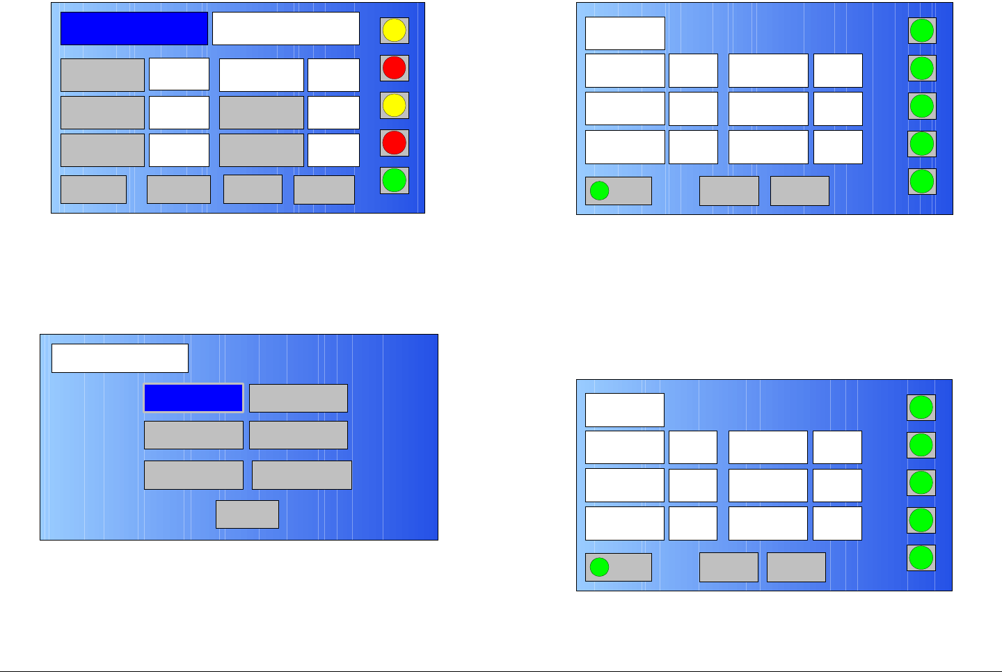
Routine Operation 3-40MTX5000 User and Technical Manual
Figure 3-72: Main Screen (Digital ASI Preset) - Typical
6. Select either Status option button and observe the
COFDM Mode Status screen is displayed. See
Figure 3-73.
Figure 3-73: COFDM Mode Status Screen
7. Select the COFDM option button and observe the
selected Preset COFDM Status screen is displayed.
See Figure 3-74.
Channel 1 0Offset
Antenna Ant. Pol.Antenna1 H
RFU2
7US
RF Band
Preset E Digital - COFDM QPSK,
8, 3/4, 1/8, ASI
RF Output XX
dBm
<- Status Setup Status ->
PA Off
SUM
ODU
IDU
RF
L/R
L
L
COFDM Mode Status
Main
COFDM
Encoder
PID
Video
Audio
IP Transfer
Figure 3-74: COFDM Status Screen
8. When review of the COFDM Status screen is
complete, select the Back option button and observe
the COFDM Mode Status screen is displayed.
9. Select the Video option button and observe the Video
Status screen is displayed. See Figure 3-75.
Figure 3-75: Video Status Screen - Typical
COFDM Status
Back
PA On
SUM
ODU
IDU
RF
L/R
H
Constellation
FEC
Data Rate
QPSK
8.294
Mbps
3/4
RF B/W
RF Output
Guard Interval
8
MHz
1/8
38.4
dBm
L
Main
Video Status
Back PA On
SUM
ODU
IDU
RF
L/R
H
Video In
Noise
Reduction
HD Test
Pattern
ASI
Input
Off
Off
FrameRate
SDI Auto Line
Video Loss
Bars
29.97HZ
Off
Off
L
Main
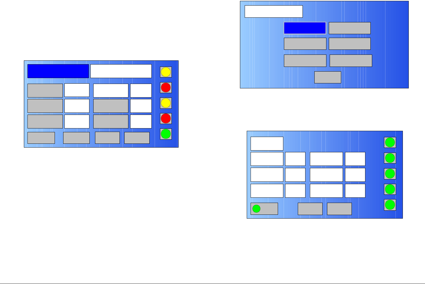
Routine Operation 3-41MTX5000 User and Technical Manual
10. When review of the Video Status screen is complete,
select the Main option button and observe the Main
screen is displayed. Procedure is complete.
11. Observe the Main screen is displayed. See Figure 3-
76.
Figure 3-76: Main Screen (Digital COFDM/LMS-T/DVB-S/
Digital IP Preset) - Typical
12. Select either Status option button and observe the
COFDM Mode Status screen is displayed. See
Figure 3-77.
Channel 9 0Offset
Antenna Ant. Pol.Antenna1 H
RFU1
2G17M
RF Band
Preset C Digital - COFDM QPSK,
4:2:0,8, 1/2, 1/8, comp
RF Output XX
dBm
<- Status Setup Status ->PA Off
SUM
ODU
IDU
RF
L/R
L
L
Figure 3-77: COFDM Mode Screen
13. Select the COFDM option button and observe the
COFDM Status screen is displayed. See Figure 3-78.
Figure 3-78: COFDM Status Screen - Typical
14. When review of the COFDM Status screen is
complete, select the Back option button and observe
the COFDM Mode Status screen is displayed.
15. Select the Video option button and observe the Video
Status screen is displayed. See Figure 3-79 on
page 3-42.
COFDM Mode Status
Main
COFDM
Encoder
PID
Video
Audio
IP Transfer
COFDM Status
Back
PA On
SUM
ODU
IDU
RF
L/R
H
Constellation
FEC
Data Rate
16QAM
18.431
Mbps
2/3
RF B/W
RF Output
Guard Interval
10
MHz
1/8
0.0 dBm
L
Main
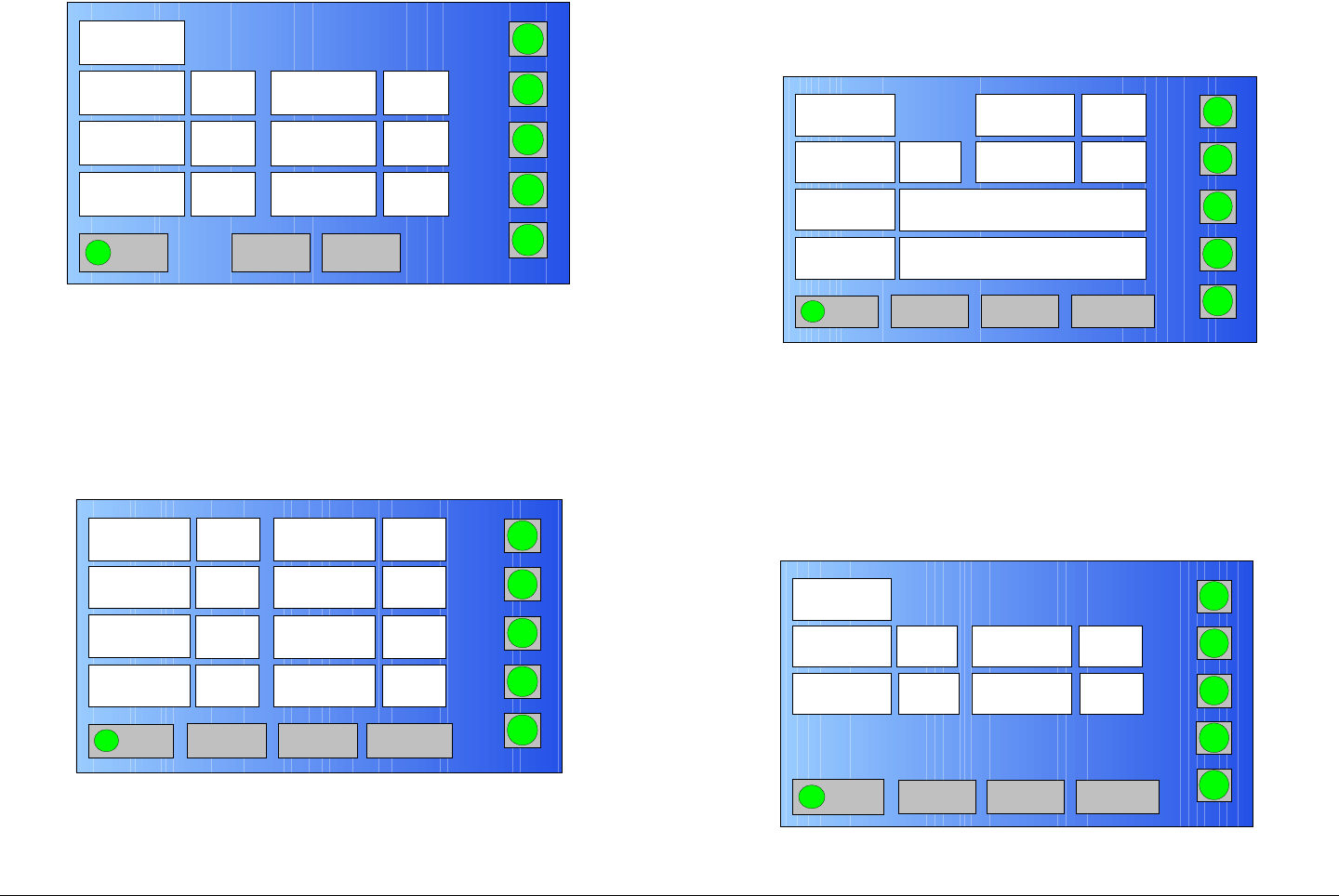
Routine Operation 3-42MTX5000 User and Technical Manual
Figure 3-79: Video Status Screen - Typical
16. When review of the Video Status screen is complete,
select the Back option button and observe the
COFDM Mode Status screen is displayed.
17. Select the Encoder option button and observe the
Encoder screen is displayed. See Figure 3-80.
Figure 3-80: Encoder Screen - Typical
18. When review of the Encoder screen is complete,
select the Encoder 2 option button and observe the
Video Status
Back PA On
SUM
ODU
IDU
RF
L/R
H
Video In
Noise
Reduction
HD Test
Pattern
ASI
Input
Off
Off
FrameRate
SDI Auto Line
Video Loss
Bars
29.97HZ
Off
Off
L
Main
Mode
Encoder 2
PA On
SUM
ODU
IDU
RF
L/R
H
Horizontal
Resolution
Spectrum
Invert
PTS per
Picture
720
Off
Normal
Aspect Ratio
VBI
Color Bars
4:3
Off
Off
Standard
Delay Chroma 4:2:0
Back L
Main
Encoder Status 2 screen is displayed. See Figure 3-
81.
Figure 3-81: Encoder Status Screen - Typical
19. When review of the Encoder Status 2 screen is
complete, select the Back option button and observe
the COFDM Mode Status screen is displayed.
20. Select the Audio option button and observe the Audio
1 Status screen is displayed. See Figure 3-82.
Figure 3-82: Audio 1 Status Screen - Typical
Encoder
Status 2
Encoder 1
PA On
IDU
RF
ODU
PA
SUM
H
Bit Rate Auto
Network Name
Service Name
On
Service 01
Net 1
Bit Rate 4.900
Mbps
GOP Length 15
Back L
Main
Audio 1 Status
Audio 2 PA On
SUM
ODU
IDU
RF
L/R
H
Mode
Standard
Dual
Mono Input Analog
Back
MPEG Bit Rate 128kb
L
Main
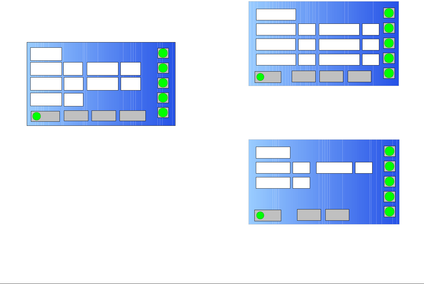
Routine Operation 3-43MTX5000 User and Technical Manual
21. When review of the Audio 1 Status screen is
complete, select the Audio 2 option button and
observe the Audio 2 Status screen is displayed. See
Figure 3-83.
Figure 3-83: Audio 2 Status Screen - Typical
22. When review of the Audio 2 Status screen is
complete, select the Back option button and observe
the COFDM Mode Status screen is displayed.
23. Select the PID option button and observe the PID
Status screen is displayed. See Figure 3-84.
Audio 2 Status
Audio 1
PA On
SUM
ODU
IDU
RF
L/R
H
Mode
Standard
Dual
Mono Input Analog
Back
MPEG Bit Rate 192kb
Balance Unbal-
anced
L
Main
Figure 3-84: PID Status Screen - Typical
24. When review of the PID Status screen is complete,
select the next option button and observe the PID
Status-2 screen is displayed. See Figure 3-85.
Figure 3-85: PID Status-2 Screen - Typical
PID Status
Main
PMT
300
32
AUDIO B 201
DATA
AUDIO A
100
200
VIDEO
PCR 8190
PA On
SUM
ODU
IDU
RF
L/R
H
L
Back Next
PID Status-2
Main
3Network ID
Transport ID
1
1
Program ID
PA On
SUM
ODU
IDU
RF
L/R
H
L
Back
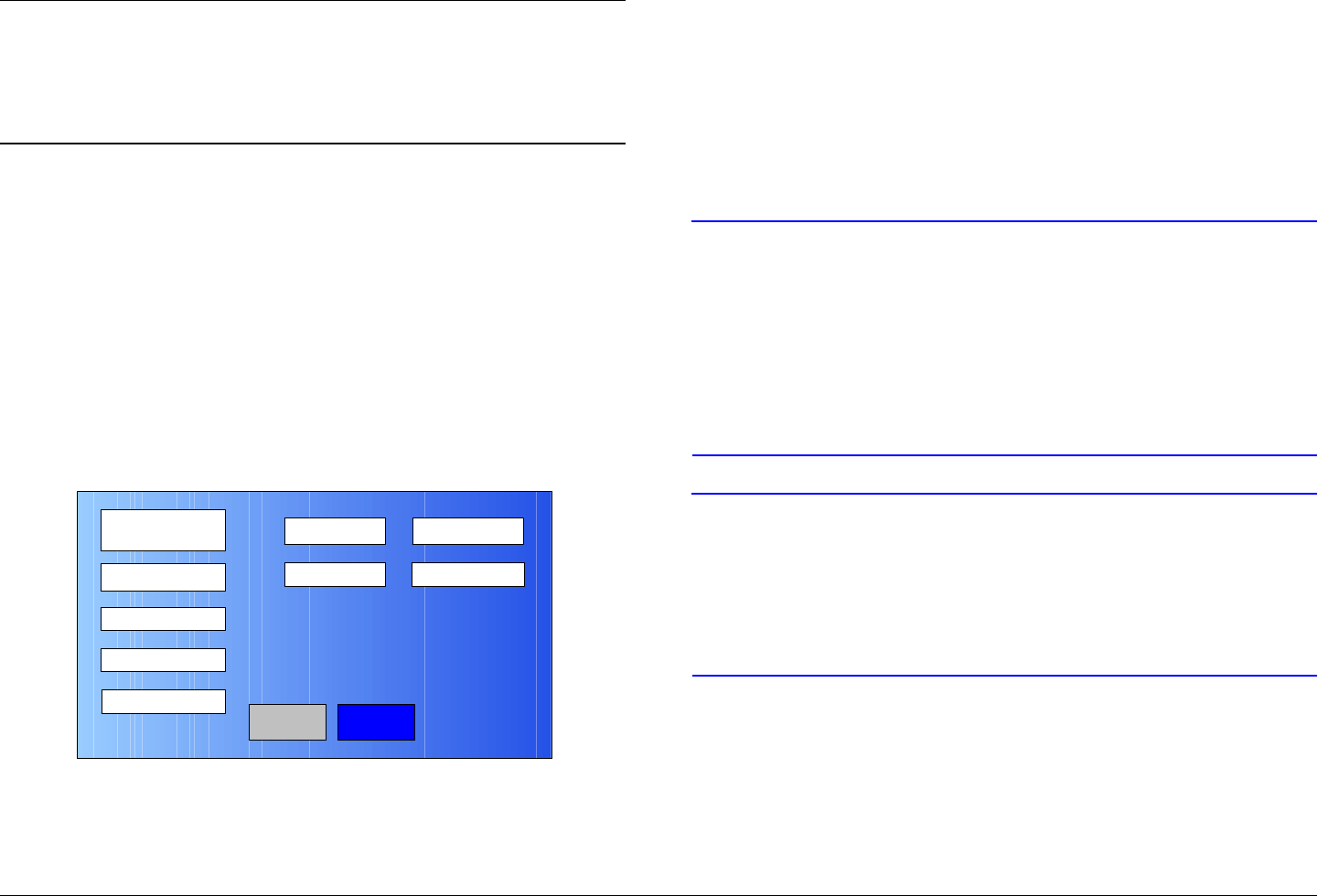
Routine Operation 3-44MTX5000 User and Technical Manual
Note If the Preset being monitored is a digital COFDM,
LMS-T, or DVB-S Preset, go to step 25.
If the Preset being monitored is a digital IP Preset,
go to step 26.
25. When review of the PID Status-2 screen is complete,
select the Main option button and observe the Main
screen is displayed. Procedure is complete.
26. When review of the PID Status-2 screen is complete,
select the Back option button and observe the PID
Status screen is displayed.
27. Select the Back option button and observe the
COFDM Mode Status screen is displayed.
28. Select the IP Transfer option button and observe the
IP Status screen is displayed. See Figure 3-86.
Figure 3-86: IP Status Screen - Typical
29. When review of the IP Status screen is complete,
select the Main option button and observe the Main
screen is displayed. Procedure is complete.
IP Status
Back
IP Transfer Mode
Max Bit Rate 19.350 Mbps
12.441 Mbps
IP + Video
Main
Video Bitrate
IP Rate
5.2 Mbps
3.6.13 Perform PA Voltage Adjust Setup
The procedure required to calibrate the PA DC voltage for each
Standard ODU (RF Unit) is contained in the following steps.
This procedure is to be performed for Standard ODUs only.
Do not perform this procedure for High Power ODUs. The
PA voltage for High Power ODUs is fixed and cannot be
adjusted.
CAUTION To avoid potential software hang-ups,
always ensure the ODU is connected to the
IDU before attempting to perform this
procedure.
Do not attempt to perform this procedure if
the ODU is not connected to the IDU, as the
software will hang up.
CAUTION To avoid potential software hang-ups, check
the Main screen ODU status indicator and
verify no major faults exist in the ODU.
If faults exist in the ODU, they must be
corrected prior to performing this procedure.
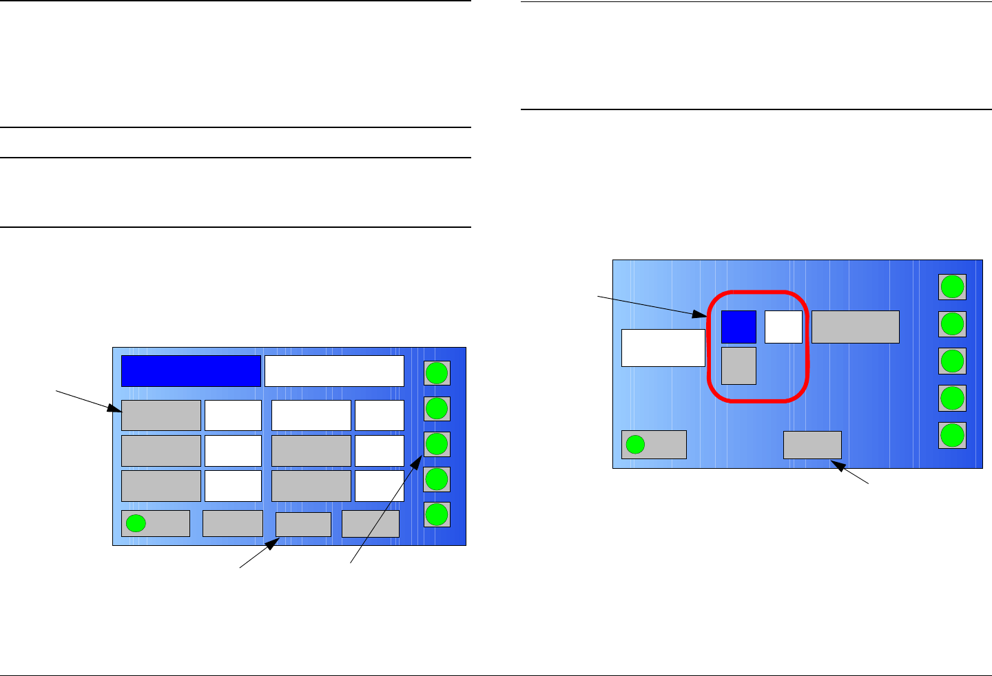
Routine Operation 3-45MTX5000 User and Technical Manual
Note This procedure should be performed following
initial installation of the MTX5000 System with a
Standard ODU, after replacement of the IDU or
Standard ODU, or following any repairs to the
cable assembly providing power from the IDU to
the Standard ODU.
Note In the following procedure, option buttons may be
selected using either the touch screen or the
function keys and the SEL key.
1. Verify the ODU status indicator does not indicate a
major fault (indicator is not red). See Figure 3-87.
Figure 3-87: Main Screen - Typical
Channel 1 0Offset
Antenna Ant. Pol.Antenna1 H
RFU2
7US
RF Band
Preset A Analog
4.83 & 5.8, 3MHz Vid Dev
RF Output XX
dBm
<- Status Setup Status ->
PA On
SUM
ODU
IDU
RF
L/R
H
L
Setup Option
Button
RF Band
Option
Button
ODU Status
Indicator
Notes If your MTX5000 system is a single band system,
go to step 5.
If your MTX5000 system is a dual band system,
perform step 2 thru step 12 for both bands.
2. Select the RF Band option button and observe the RF
Band screen is displayed and the current RF band
option button is highlighted. See Figure 3-88,
Figure 3-89 on page 3-46, Figure 3-90 on page 3-46,
or Figure 3-91 on page 3-46.
Figure 3-88: RF Band Screen - Typical
2GHz Change Plan
RFU2
RFU1
RF Band
Main
PA On
SUM
ODU
IDU
RF
L/R
H
L
Main Screen
Option Button
RF Band
Option
Buttons
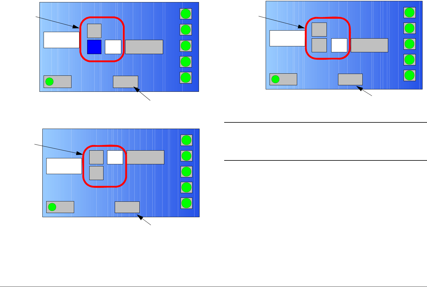
Routine Operation 3-46MTX5000 User and Technical Manual
Figure 3-89: RF Band 2 GHz RFU2 Option Screen
Figure 3-90: RF Band 7 GHz RFU1 Option Screen
RFU2
RFU1
RF Band
Main
PA On
SUM
RF
IDU
RF
L/R
H
L
2GHz Change Plan
Main Screen
Option Button
RF Band
Option
Buttons
RFU2
RFU1
RF Band
Main
PA On
SUM
ODU
IDU
RF
SUM
H
L
7GHz Change Plan
Main Screen
Option Button
RF Band
Option
Buttons
Figure 3-91: RF Band 7 GHz RFU2 Option Screen
Note In the following step, the RECONFIGURING
RADIO screen (Figure 3-92 on page 3-47) will be
displayed only if the RF Band RFU1 or RFU2
option switch option is changed.
3. Select the RFU1 or RFU2 option button, as required,
and observe the RECONFIGURING RADIO screen
(Figure 3-92 on page 3-47) is displayed.
RFU2
RFU1
RF Band
Main
PA On
SUM
ODU
IDU
RF
L/R
H
L
2GHz Change Plan
Main Screen
Option Button
RF Band
Option
Buttons
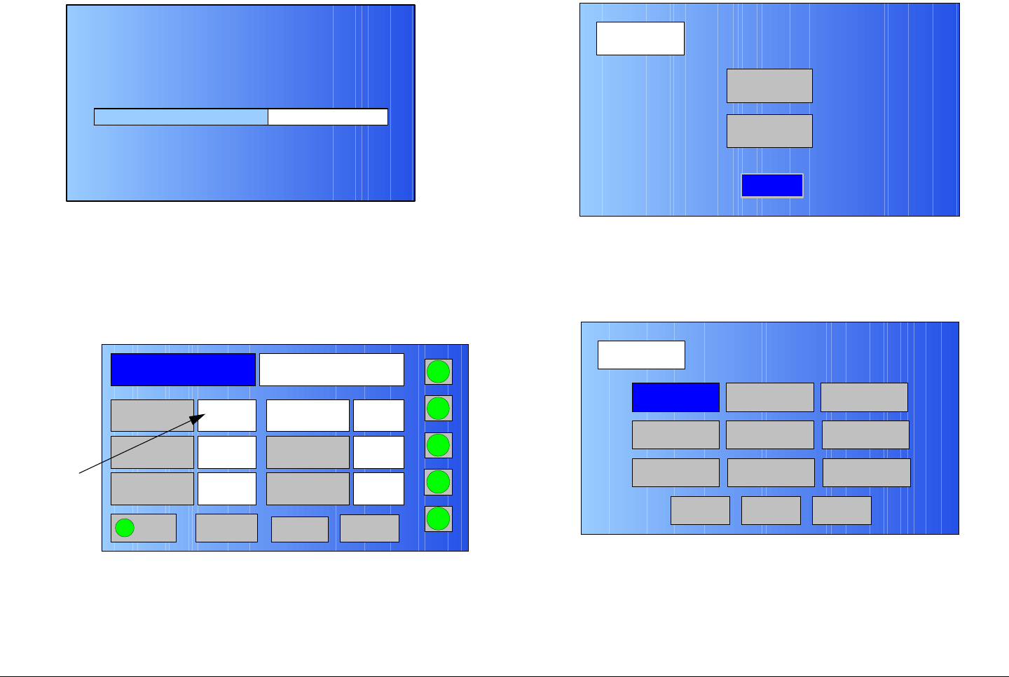
Routine Operation 3-47MTX5000 User and Technical Manual
Figure 3-92: RECONFIGURING RADIO Screen - Typical
4. After a short delay, observe the RF Band screen is
displayed, select the Main option button, and observe
the RF band setting required is displayed. See
Figure 3-93.
Figure 3-93: Main Screen - Typical
5. Select the Setup option button and observe the Setup
screen is displayed. See Figure 3-94.
60 %
RECONFIGURING RADIO. PLEASE WAIT!
DO NOT POWER OFF RADIO UNTIL RECONFIGURED!
Channel 1 0Offset
Antenna Ant. Pol.Antenna1 V
RFU2
7US
RF Band
Preset A Analog
4.83 & 5.8, 3MHz Vid Dev
RF Output XX
dBm
<- Status Setup Status -> PA On
SUM
ODU
IDU
RF
L/R
H
L
RF Band
Setting
Figure 3-94: Setup Screen
6. Select the Radio option button and observe the Radio
screen is displayed. See Figure 3-95.
Figure 3-95: Radio Screen
7. Select the Calibration option button and observe the
PA Voltage Adjust Setup screen is displayed. See
Figure 3-96 on page 3-48.
Setup
User
Main
Radio
Radio
Back
Network Config Level Adjust Color Bars
Calibration
Time & Date
Change Pwd
System Info
License Key
Diagnostics
NextMain
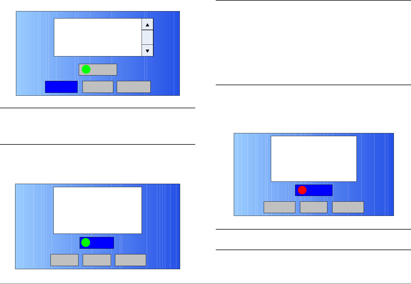
Routine Operation 3-48MTX5000 User and Technical Manual
Figure 3-96: PA Voltage Adjust Setup Screen
Notes If using the function keys and SEL key to select the
Start option button, go to step 8.
If using the touch screen, go to step 9.
8. Select the Start option button and observe the Start
option button becomes active (blue). See Figure 3-97.
Figure 3-97: PA Voltage Adjust Setup Screen - Start
<-Previous
Start
Factory->
This process will allow you to calibrate
the PA DC voltage for each specific
frequency band. Once you have the
Radio connected to the ODU
and are ready to start calibration,
Press the START Button below
Main
Start
<-Previous Factory->
Welcome to the PA Voltage Adjust Setup
Screen!
This process will allow you to calibrate
the PA DC voltage for each specific
frequency band. Once you have the
Radio connected to the ODU
and are ready to start calibration, press
the START Button below
Main
Notes When the Start option button is selected in the
following step, calibration will begin and the Start
option button indicator will change from green to
red.
It will take approximately 30 seconds for the
calibration process to be completed.
When calibration is complete, the Start option
button indicator will change from red to green.
9. Select the Start option button and observe the Start
option button indicator turns red and the Starting the
Calibration... message is displayed. See Figure 3-98.
Figure 3-98: Starting Calibration
Note Do not select the Factory option button. The
Factory option button is used for factory test only.
10. When calibration is complete, observe the Calibration
Successful message is displayed. See Figure 3-99
on page 3-49.
Start
Starting the Calibration...
<-Previous Factory->
Main
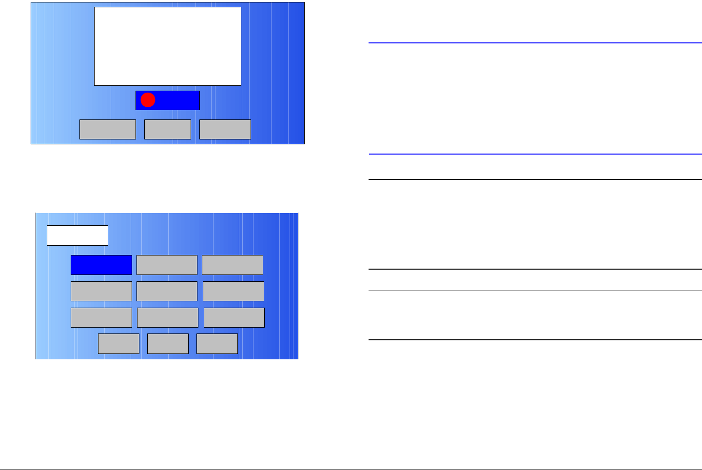
Routine Operation 3-49MTX5000 User and Technical Manual
Figure 3-99: Calibration Successful
11. Select the Previous option button and observe the
Radio screen is displayed. See Figure 3-100.
Figure 3-100: Radio Screen
12. Select the Main option button and observe the Main
screen is displayed.
3.6.14 Perform RF Level Adjust
The procedure required to adjust the RF output level when
operating in the digital mode is contained in the following steps.
Start
Calibration Successful
<-Previous Next->
Main
Radio
Back
Network Config Level Adjust Color Bars
Calibration
Time & Date
Change Pwd
System Info
License Key
Diagnostics
NextMain
This procedure provides the means to adjust the RF level output
manually (not recommended), if required. This procedure also
provides the steps to select the Auto mode (recommended).
CAUTION It is highly recommended that the RF output
level be set to the Auto mode for optimum
performance.
Manually setting the RF output level runs
the risk of exceeding the FCC mask or of
deteriorating digital performance.
Notes The RF output level can only be adjusted if you are
operating in the digital mode with a digital Preset
selected.
The RF output level cannot be adjusted if you are
operating in the analog mode.
Note In the following procedure, option buttons may be
selected using either the touch screen or the
function keys and the SEL key.
1. Observe the Main screen is displayed. See Figure 3-
101 on page 3-50.
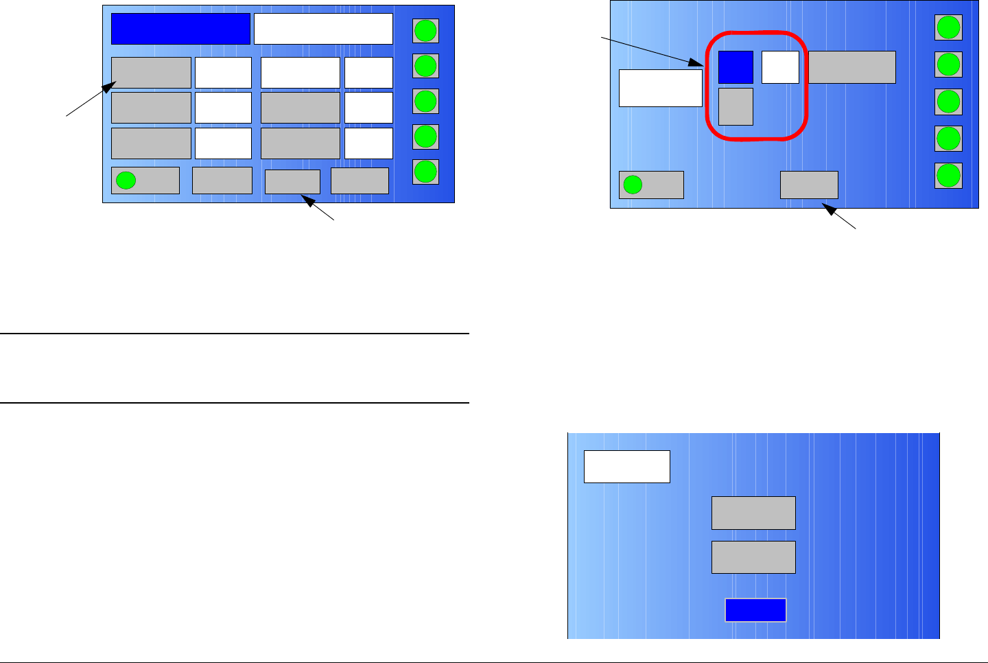
Routine Operation 3-50MTX5000 User and Technical Manual
Figure 3-101: Main Screen - Typical
2. Select a digital Preset per “Select Preset” on page 3-
24, as required.
Note If your MTX5000 system is a dual band system,
step 3 thru step 10 must be performed for both
bands.
3. Select the RF Band option button and observe the RF
Band screen is displayed and the current RF band
option button is highlighted. See Figure 3-102.
Channel 1 0Offset
Antenna Ant. Pol.Antenna1 H
RFU2
7US
RF Band
Preset A Analog
4.83 & 5.8, 3MHz Vid Dev
RF Output XX
dBm
<- Status Setup Status ->
PA On
SUM
ODU
IDU
RF
L/R
H
L
Setup Option
Button
RF Band
Option
Button
Figure 3-102: RF Band Screen - Typical
4. Select the RF band option button required, observe
the RF Band screen is displayed, select the Main
option button, observe the Main screen is displayed,
and observe the new RF band setting is displayed.
5. Select the Setup option button and observe the Setup
screen is displayed. See Figure 3-103.
Figure 3-103: Setup Screen
2GHz Change Plan
RFU2
RFU1
RF Band
Main
PA On
SUM
ODU
IDU
RF
L/R
H
L
Main Screen
Option Button
RF Band
Option
Buttons
Setup
User
Main
Radio
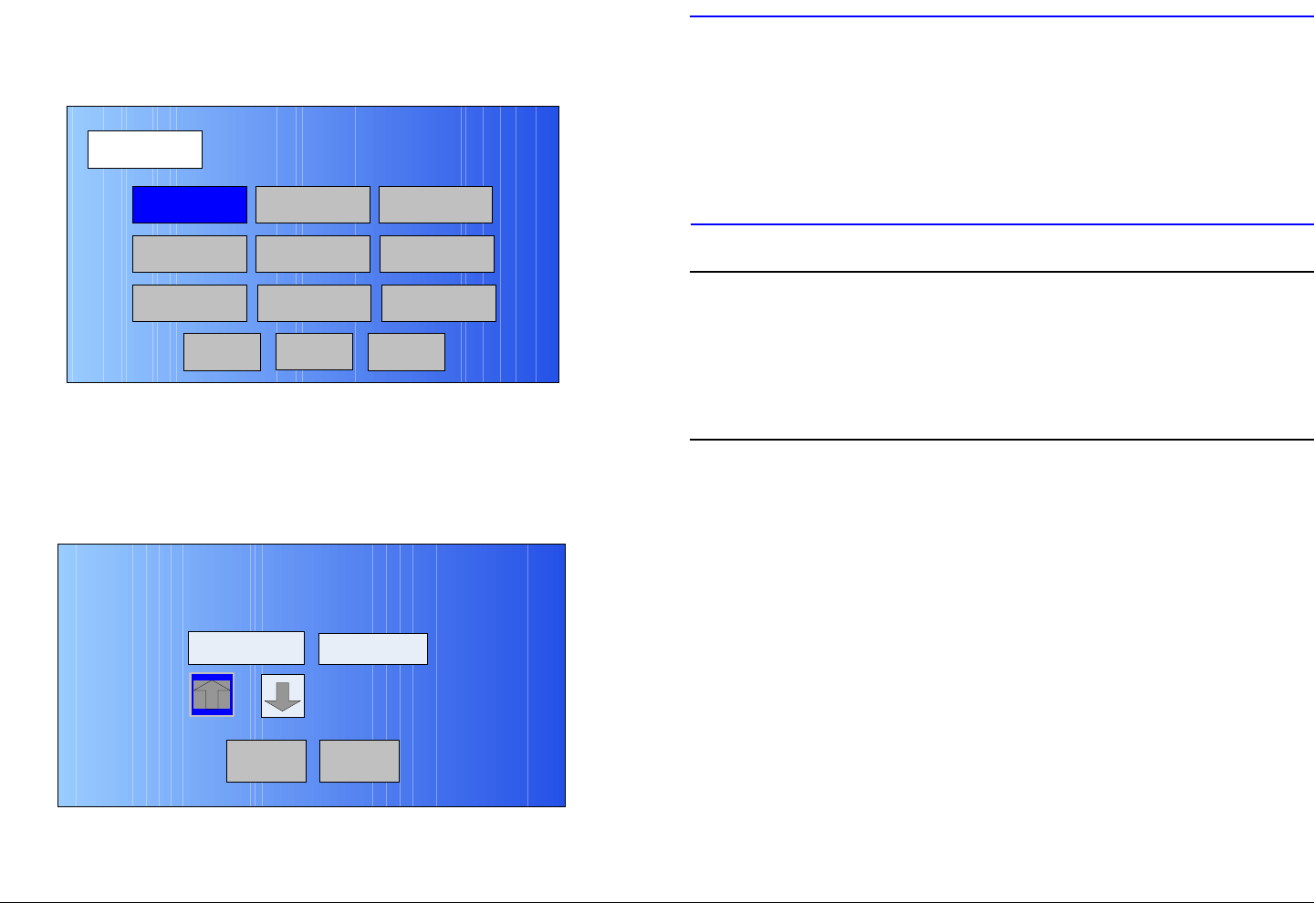
Routine Operation 3-51MTX5000 User and Technical Manual
6. Select the Radio option button and observe the Radio
screen is displayed. See Figure 3-104.
Figure 3-104: Radio Screen
7. Select the Level Adjust option button and observe the
RF Output Level Adjust screen is displayed. See
Figure 3-105.
Figure 3-105: RF Output Level Adjust Screen
Radio
Back
Network Config Level Adjust Color Bars
Calibration
Time & Date
Change Pwd
System Info
License Key
Diagnostics
NextMain
Back
RF Output Level Adjust
Attenuation Output Power
Auto 40.0 dBm
Main
CAUTION It is highly recommended that the RF output
level be set to the Auto mode for optimum
performance.
Manually setting the RF output level runs
the risk of exceeding the FCC mask or
deteriorating digital performance.
Notes In the following steps, Attenuation level options
available are Auto or 0 to 15.
The Auto option is the optimum attenuation level
set at the factory and is the recommended
Attenuation level option.
8. Select the RF Output Level Adjust screen Up or
Down arrow option buttons to select the Attenuation
level required. Options are Auto or 0 to 15 (Auto
recommended).
9. When the Attenuation setting required has been
selected, select the Back option button and observe
the Radio screen is displayed. See Figure 3-106 on
page 3-52.
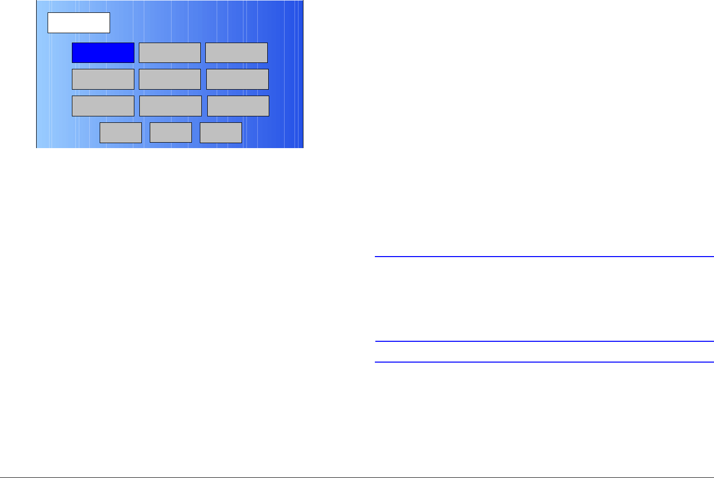
Routine Operation 3-52MTX5000 User and Technical Manual
Figure 3-106: Setup Screen
10. Select the Main option button and observe the Main
screen is displayed.
3.6.15 Select Color Bar Generator Mode
All MTX5000 IDUs contain a built-in digital Color Bar Generator
(CBG). An optional analog CBG is available. The procedure
required to select the CBG operating mode is contained in the
following steps.
The CBG has four operating modes that may be selected as
follows:
•Off - Color bars and audio test tones are turned off.
•On - Color bars and audio test tones are continuously
turned on. This mode should be used for test or
troubleshooting only.
•A Gen (Auto Generated) - If a loss of video signal occurs,
color bars and/or audio test tones are transmitted after a
specified delay.
•A Stby (Auto Standby) - If a loss of video signal occurs,
the transmitter is automatically placed into standby (PA is
turned off).
Radio
Back
Network Config Level Adjust Color Bars
Calibration
Time & Date
Change Pwd
System Info
License Key
Diagnostics
NextMain
The same Color Bars screen is displayed when making either
analog or digital CBG option selections. When configuring your
IDU CBG options, the following rules must be observed:
• If you have the optional analog CBG contained in your
IDU, selection of the Color Bars screen Off, On, A Gen,
or A Stby option will be applicable to all analog and digital
Presets. You cannot select different Color Bars screen
options for different Presets.
• If you do not have the optional analog CBG installed in
your IDU, selection of the Color Bars screen On, A Gen,
or A Stby option will be applicable to digital Presets only.
No options are available for analog Presets if you do not
have the optional analog CBG.
• If you do not have the optional analog CBG installed in
your IDU and you select the Color Bars screen On, A
Gen, or A Stby option, selection of an analog Preset will
result in no audio, video, or color bar outputs.
CAUTION If you do not have the optional Analog Color
Bar Generator installed in your MTX5000
IDU and you set the Color Bar Generator to
On, A Gen, or A Stby, a blank screen will
be displayed for all analog Presets.
CAUTION To avoid potential problems that could
impact operation of the MTX5000 System,
always select the Color Bars screen Off, A
Gen, or A Stby options for normal
operation.
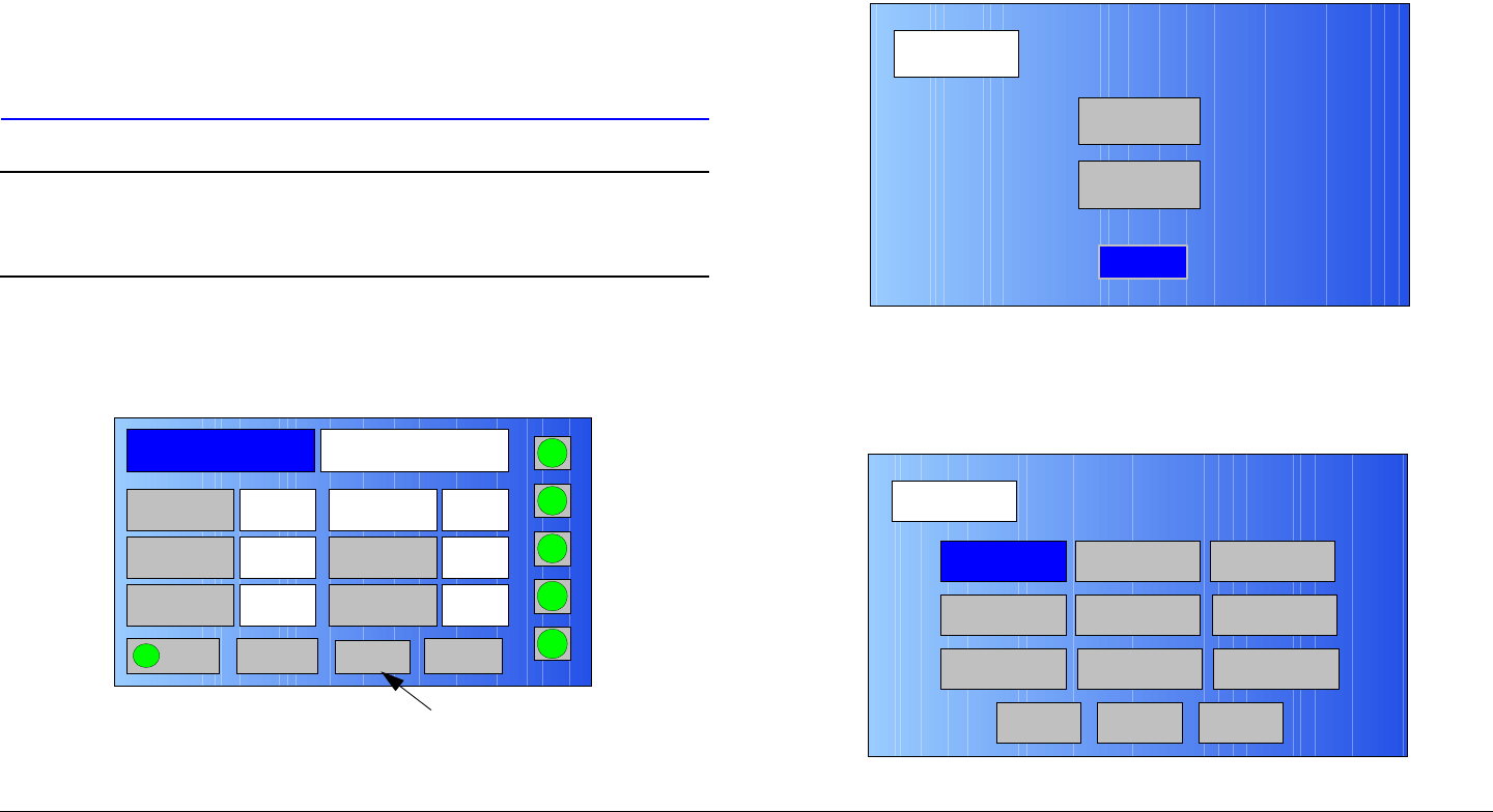
Routine Operation 3-53MTX5000 User and Technical Manual
The On operating mode should only be
selected when testing or troubleshooting.
When the On option is selected, color bars
take priority over all Preset settings.
Selection of the On option will transmit color
bars at all times in both analog and digital
Presets if you have the optional analog CBG
and will transmit color bars at all times in
digital Presets only, if you do not have the
optional analog CBG.
Note In the following procedure, option buttons may be
selected using either the touch screen or the
function keys and the SEL key.
1. Observe the Main screen is displayed. See Figure 3-
107.
Figure 3-107: Main Screen - Typical
Channel 1 0Offset
Antenna Ant. Pol.Antenna1 H
RFU2
7US
RF Band
Preset A Analog
4.83 & 5.8, 3MHz Vid Dev
RF Output XX
dBm
<- Status Setup Status ->
PA On
SUM
ODU
IDU
RF
L/R
H
L
Setup Option
Button
2. Select any Preset per “Select Preset” on page 3-24, as
required.
3. Verify the Main screen is displayed.
4. Select the Setup option button and observe the Setup
screen is displayed. See Figure 3-108.
Figure 3-108: Setup Screen
5. Select the Radio option button and observe the Radio
screen is displayed. See Figure 3-109.
Figure 3-109: Radio Screen
Setup
User
Main
Radio
Radio
Back
Network Config Level Adjust Color Bars
Calibration
Time & Date
Change Pwd
System Info
License Key
Diagnostics
Next
Main
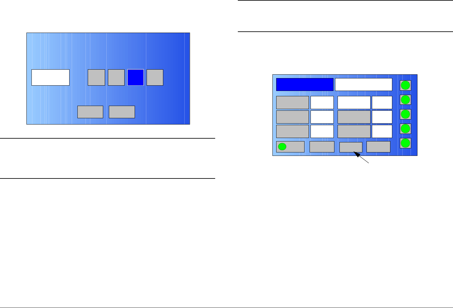
Routine Operation 3-54MTX5000 User and Technical Manual
6. Select the Color Bars option button and observe the
Color Bars screen is displayed. See Figure 3-110.
Figure 3-110: Color Bars Screen
Note If the On operating mode option is selected in the
following step for test or troubleshooting, repeat
step 7 to select Off, A Gen, or A Stby, as required,
when test or trouble-shooting is complete.
7. Select the Off, On, A Gen, or A Stby operating mode
option button, as required.
8. Select the Color Bars screen Main option button and
observe the Main screen is displayed.
3.6.16 Set Time and Date
The procedure required to set the date and time is contained in
the following steps.
Color Bars A GenOnOff A Stby
Back Main
Note In the following procedure, option buttons may be
selected using either the touch screen or the
function keys and the SEL key.
1. Observe the Main screen is displayed. See Figure 3-
111.
Figure 3-111: Main Screen - Typical
2. Select the Setup option button and observe the Setup
screen is displayed. See Figure 3-112 on page 3-55.
Channel 1 0Offset
Antenna Ant. Pol.Antenna1 H
RFU2
7US
RF Band
Preset A Analog
4.83 & 5.8, 3MHz Vid Dev
RF Output XX
dBm
<- Status Setup Status ->
PA On
SUM
ODU
IDU
RF
L/R
H
L
Setup Option
Button
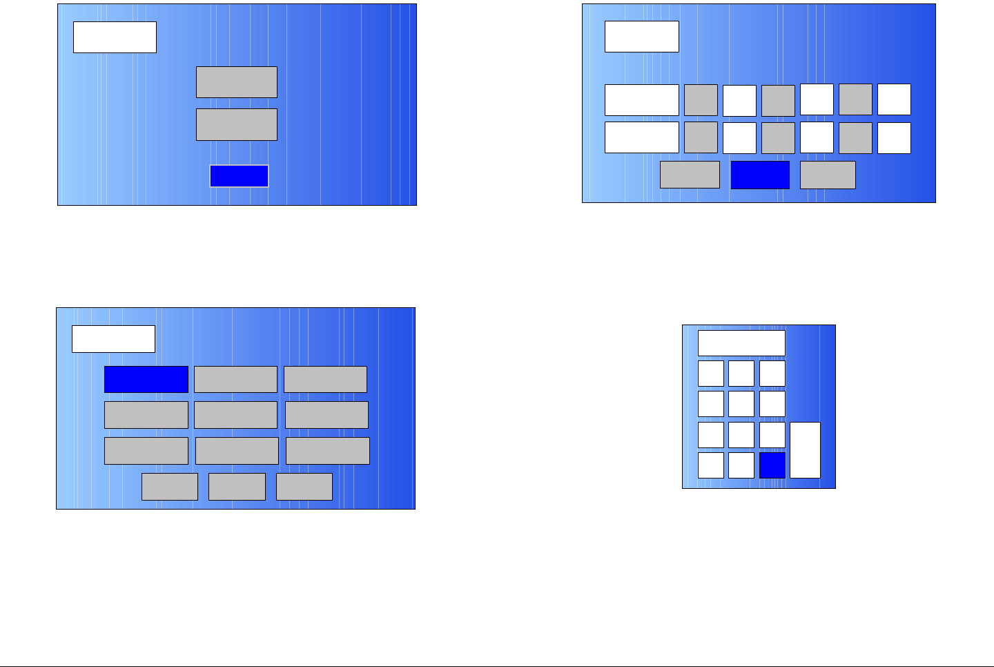
Routine Operation 3-55MTX5000 User and Technical Manual
Figure 3-112: Setup Screen
3. Select the Radio option button and observe the Radio
screen is displayed. See Figure 3-113.
Figure 3-113: Radio Screen
4. Select the Time & Date option button and observe the
Time/Date screen is displayed. See Figure 3-114.
Setup
User
Main
Radio
Radio
Back
Network Config Level Adjust Color Bars
Calibration
Time & Date
Change Pwd
System Info
License Key
Diagnostics
Next
Main
Figure 3-114: Time / Date Screen - Typical
5. Select the Year, Month, Day, Hour, Min., and/or Sec.
option buttons, as required, and observe the numeric
keypad is displayed. See Figure 3-115.
Figure 3-115: Keypad
6. Enter the value required, select the ENT key, and
observe the Time / Date screen is displayed.
7. When all date and time entries are complete, select
the Submit option button and observe the Radio
screen is displayed.
8. Select the Main option button and observe the Main
screen is displayed.
Time / Date
Submit Cancel
Date
Time Hour
Year
8
2009
Min.
Month
30
3
Sec.
Day
30
17
Tue – Mar 17, 2009 – 08:30:30
Main
1 2 3
4
7
5 6
8 9
CLR 0ESC
ENT
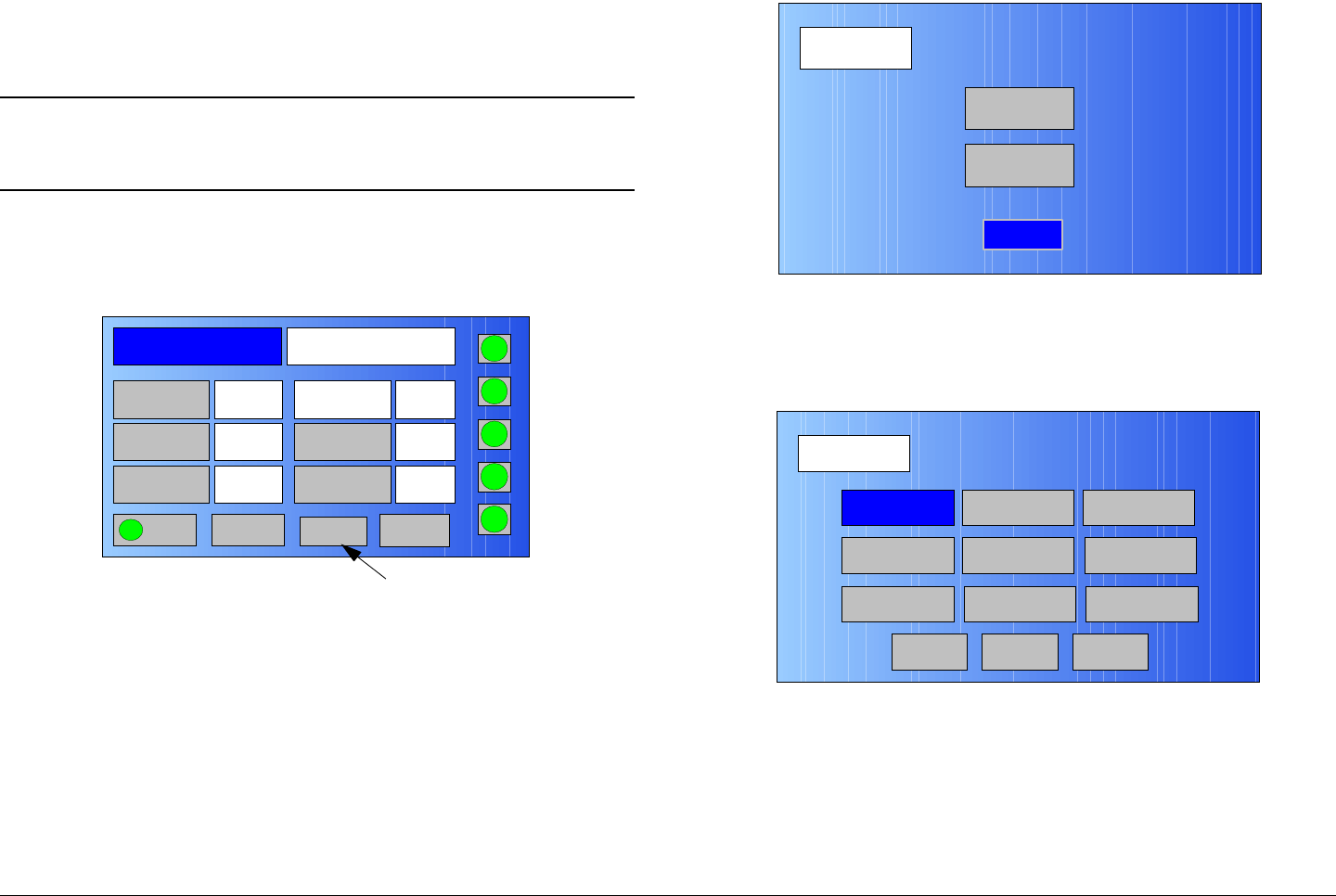
Routine Operation 3-56MTX5000 User and Technical Manual
3.6.17 Perform IDU Diagnostics
The procedure required to perform IDU diagnostics are
contained in the following steps.
Note In the following procedure, option buttons may be
selected using either the touch screen or the
function keys and the SEL key.
1. Observe the Main screen is displayed. See Figure 3-
116.
Figure 3-116: Main Screen - Typical
2. Select the Setup option button and observe the Setup
screen is displayed. See Figure 3-117.
Channel 1 0Offset
Antenna Ant. Pol.Antenna1 H
RFU2
7US
RF Band
Preset A Analog
4.83 & 5.8, 3MHz Vid Dev
RF Output XX
dBm
<- Status Setup Status ->
PA On
SUM
ODU
IDU
RF
L/R
H
L
Setup Option
Button
Figure 3-117: Setup Screen
3. Select the Radio option button and observe the Radio
screen is displayed. See Figure 3-118.
Figure 3-118: Radio Screen
4. Select the Diagnostics option button and observe the
Diagnostics screen is displayed. See Figure 3-119
on page 3-57.
Setup
User
Main
Radio
Radio
Back
Network Config Level Adjust Color Bars
Calibration
Time & Date
Change Pwd
System Info
License Key
Diagnostics
Next
Main
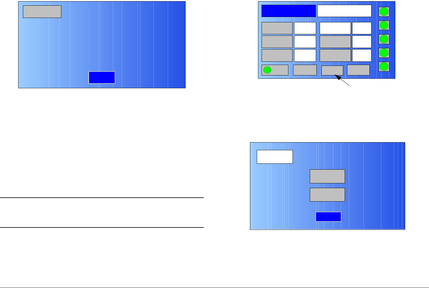
Routine Operation 3-57MTX5000 User and Technical Manual
Figure 3-119: Diagnostics Screen - Typical
5. When review of the Diagnostics screen is complete,
select the Back option button and observe the Radio
screen is displayed.
6. Select the Main option button and observe the Main
screen is displayed.
3.6.18 Review System Information
The procedure required to review the current software versions
contained in your MTX5000 IDU is contained in the following
steps.
Note In the following procedure, option buttons may be
selected using either the touch screen or the
function keys and the SEL key.
1. Observe the Main screen is displayed. See Figure 3-
120.
Diagnostics
Back
IDU +24V +26.41V
IDU +12V +13.12V
IDU -12V -13.20V
IDU +5.5V +5.3V
IDU Fan monitor 329.28mA
IDU Temperature +0.00oC
Figure 3-120: Main Screen - Typical
2. Select the Setup option button and observe the Setup
screen is displayed. See Figure 3-121.
Figure 3-121: Setup Screen
3. Select the Radio option button and observe the Radio
screen is displayed. See Figure 3-122 on page 3-58.
Channel 1 0Offset
Antenna Ant. Pol.Antenna1 H
RFU2
7US
RF Band
Preset A Analog
4.83 & 5.8, 3MHz Vid Dev
RF Output XX
dBm
<- Status Setup Status ->
PA On
SUM
ODU
IDU
RF
L/R
H
L
Setup Option
Button
Setup
User
Main
Radio
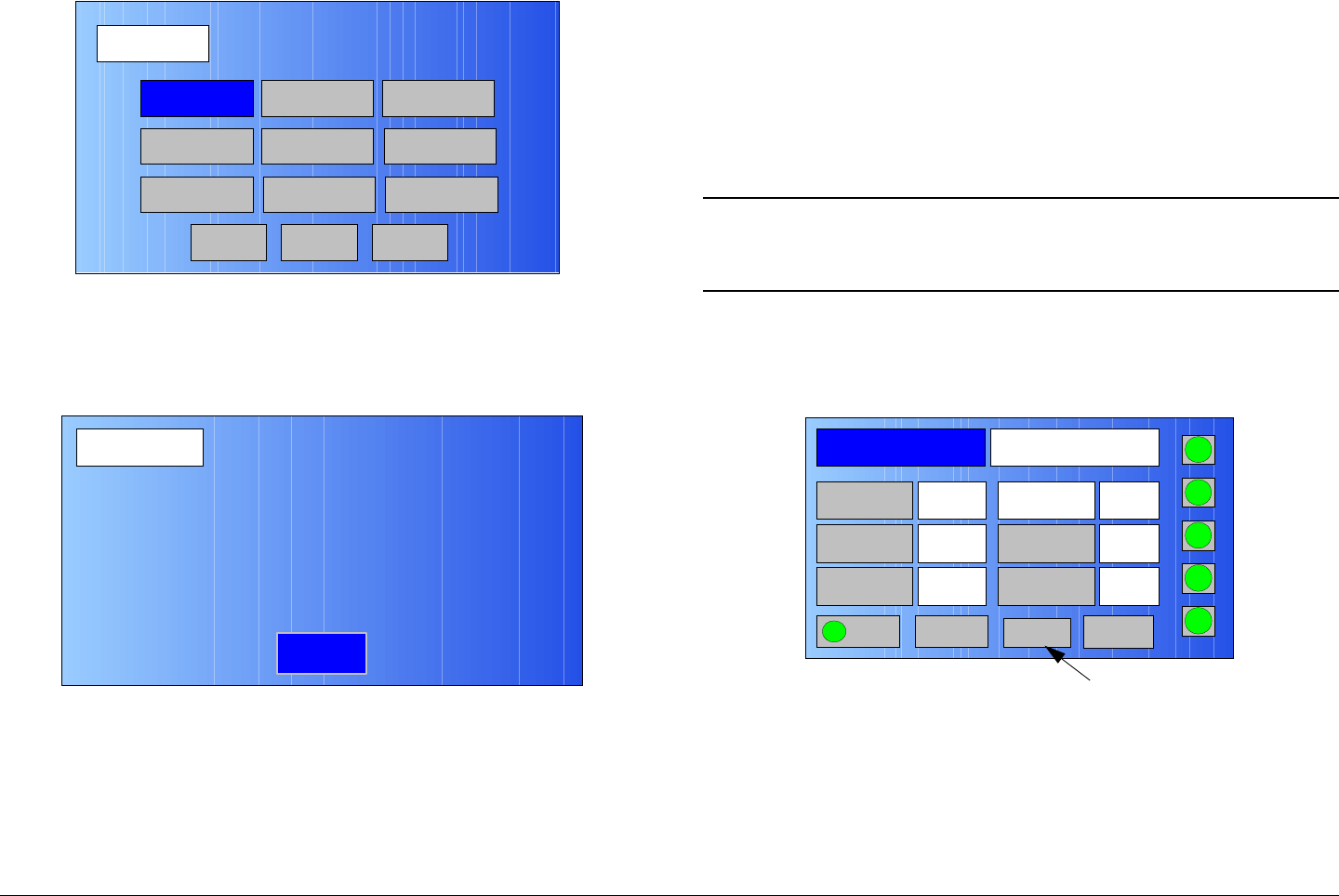
Routine Operation 3-58MTX5000 User and Technical Manual
Figure 3-122: Radio Screen
4. Select the System Info option button and observe the
System Info screen is displayed. See Figure 3-123.
Figure 3-123: System Info Screen - Typical
5. When review of the System Info screen is complete,
select the Back option button and observe the Radio
screen is displayed.
6. Select the Main option button and observe the Main
screen is displayed.
Radio
Back
Network Config Level Adjust Color Bars
Calibration
Time & Date
Change Pwd
System Info
License Key
Diagnostics
Next
Main
System Info
Back
MTX5000 Control Software V.00.04.XX
Serial #: XXXXX_XX
Date of Manufacture: 03.17.09
System Type Type 11
2.0.0 Analog Software 2.0.1
SCM Software 3.0.1
MPEG Software
3.6.19 Set Last PA State
The IDU can be configured to return the PA to the last operating
state (PA Off, PA On, or always PA Off) when the unit is
powered down and is then powered up again. After powering
down, the next time the IDU is powered up, the PA will return to
the state selected. The procedure required to set the last PA
state is contained in the following steps.
Note In the following procedure, option buttons may be
selected using either the touch screen or the
function keys and the SEL key.
1. Observe the Main screen is displayed. See Figure 3-
124.
Figure 3-124: Main Screen - Typical
2. Select the Setup option button and observe the Setup
screen is displayed. See Figure 3-125 on page 3-59.
Channel 1 0Offset
Antenna Ant. Pol.Antenna1 H
RFU2
7US
RF Band
Preset A Analog
4.83 & 5.8, 3MHz Vid Dev
RF Output XX
dBm
<- Status Setup Status ->
PA On
SUM
ODU
IDU
RF
L/R
H
L
Setup Option
Button
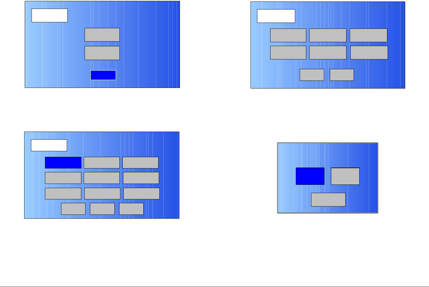
Routine Operation 3-59MTX5000 User and Technical Manual
Figure 3-125: Setup Screen
3. Select the Radio option button and observe the Radio
screen is displayed. See Figure 3-126.
Figure 3-126: Radio Screen
4. Select the Next option button and observe the
Radio - 2 screen is displayed. See Figure 3-127.
Setup
User
Main
Radio
Radio
Back
Network Config Level Adjust Color Bars
Calibration
Time & Date
Change Pwd
System Info
License Key
Diagnostics
Next
Main
Figure 3-127: Radio - 2 Screen
5. Select the PA State Option button and observe the
Select PA State Option screen is displayed. See
Figure 3-128.
Figure 3-128: Select PA State Option Screen
Radio - 2
Back
Presets Option
Load Presets
from File
Remote Ctrl
Option
Save Presets
to File
PA State
Option
Restore Presets
to Defaults
Main
LastOff
Back
Select PA State Option

Routine Operation 3-60MTX5000 User and Technical Manual
Note In the following step, if the Off option button is
selected, the PA will return to the PA Off state
when the IDU is powered up again.
If the Last option button is selected, the IDU will
return to the last PA settings that were in use when
the unit was powered down, including frequency
and power levels and PA On or PA Off state, when
the unit is powered up again.
6. Select Off or Last, as required, and observe the
Radio - 2 screen is displayed.
7. Select the Main option button and observe the Main
screen is displayed.
3.7 Using the MTX5000 in Remote
Mode
Note Remote location operations are best performed
using Internet Explorer 7.0 or later.
Once the MTX5000 is powered up, you will be able to monitor
and/or change certain operating parameters through the use of
options displayed on a PC at a remote location. The PC must be
connected to your MTX5000 via your web browser.
Notes If you are using the optional Remote Access
Subnotebook PC for remote control operations,
refer to the Remote Access Subnotebook PC
Operator’s Guide, part no. 400573-1, for the
procedures required to connect to the MTX5000
IDU and to power up the Remote Access
Subnotebook PC.
The procedures required to control the MTX5000
IDU remotely using a PC from a remote location or
for remote control using the optional Remote
Access Subnotebook PC are identical.
3.7.1 Overview
As you operate the MTX5000 from a PC at a remote location,
you will interact with the MTX5000 via a web browser. The
optional Remote Access Subnotebook PC may also be used for
mobile remote control operations.
In order to control the MTX5000 remotely via either method,
perform “Select Local/Remote Operation Mode” on page 3-20 to
place the MTX5000 in the remote mode.
The L/R option button on the MTX5000 color LCD display panel
touch screen may be selected to change the operating mode to
local (L) only. See Figure 3-129 on page 3-61. Selecting the L/
R option button when the system is in the local mode will not
change to the remote mode.
When the option button is in the local mode, all operations must
be performed at the MTX5000. When the option button is in the
remote mode, all operations must be performed at the remote
PC.
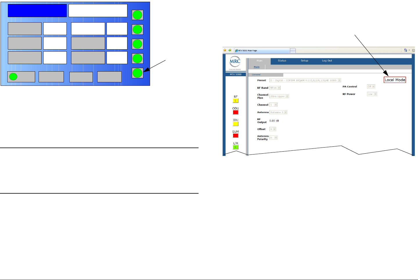
Routine Operation 3-61MTX5000 User and Technical Manual
Figure 3-129: MTX5000 Color LCD Display Panel - Typical
Selection of the local/remote operating mode may only be
performed at the MTX5000. You cannot change the local/
remote operating mode from the remote PC.
3.7.2 Remote Screen Display
Notes Preset configuration settings will be displayed in
the local mode when you are connected to the
MTX5000 IDU via your web browser. All
configuration option settings are inactive in the
local mode, however.
When you are connected to the MTX5000 via your web browser
and are logged in as a user, the display shown in Figure 3-130
will appear on your remote PC display.
When the MTX5000 is in the local mode, the Local Mode
indicator on the remote screen Main tab will be displayed after
logging in using the user password. In the local mode, the
current MTX5000 Preset configuration settings may be
monitored from the remote PC, but no settings can be changed
Channel 1 0Offset
Antenna Ant. Pol.Antenna1 V
RFU1
2G17M
RF Band
Preset A Analog
4.83 & 5.8, 3MHz Vid Dev
RF Output XX
dBm
<- Status Setup Status ->
PA On
SUM
ODU
IDU
RF
L/R
H
L
L/R Option
Button
in the local mode. When the MTX5000 is in the remote mode,
no indicator is displayed on the remote screen.
Figure 3-130: Remote Screen Display - Typical
In the remote mode, the following MTX5000 settings can be
monitored and/or changed using the remote PC. These settings
are controlled using the Main tab.
•Select Preset
•Select RF Band
•Select Channel Plan
• Select frequency Channel
•Select Antenna
• Monitor current RF Output level
• Select channel frequency Offset
Local Mode
Indicator

Routine Operation 3-62MTX5000 User and Technical Manual
• Select Antenna Polarity
• Select PA Control (transmitter) operation
• Select RF Power level
• Monitor ODU, IDU, and SUM (summary) alarms
• Monitor currently selected Preset configuration settings.
See Figure 3-131 on page 3-63 for the top level remote menu
hierarchy.
The remote screen Main tab is your starting point for navigating
through various option selections available. The remote screen
provides access to options available in your MTX5000 through
the use of various tabs and pull-down menus.
When a tab is selected, the tab is grey. Tabs will be blue when
they are not selected. The mouse cursor will change to a “hand”
icon (-) when the cursor is moved over an active tab. If an
active tab is selected and the cursor is moved over the active
tab, the cursor will not change to the “hand” icon, however.
When an active tab is selected, any additional active tabs
associated with the active tab may be selected. For example, if
an analog Preset is selected, the Main, Status, and Log Out
tabs will be active. The Setup tab is active only when a custom
user or the system administrator has logged in.
Tab options available from the Status tab are those applicable to
the licensed options contained in your MTX5000 IDU only.
Routine Operation 3-63MTX5000 User and Technical Manual
Figure 3-131: Top Level Remote Menu Hierarchy
Main Tab
Preset
RF Band
Channel Plan
Channel
Antenna
RF Output
Offset
Antenna Polarity
PA Control
RF Power
ODU
IDU
SUM
Status Tab
Antenna Polarity
Select H, V, RC, or
HC
Antenna
Select Antenna 1
or Antenna 2
Channel
Select 1 thru 10, 1
thru 14, or 1 thru 22,
as applicable to the
channel plan
RF Band
Select RFU1 or
RFU2
ODU
Monitor current ODU
alarms
RF Power
Select Low power
or High power
Preset
Select factory or
custom Presets
IDU
Monitor current IDU
alarms
SUM
Monitor current
summary alarms
PA Control
Select Off or On
Channel Plan
Select 2GHz Upper,
2GHz Lower, 2GHz
BAS, 5 GHz, 7GHz
Upper, 7GHz Lower,
or 13 GHz
RF Output
Monitor current RF
output level
Offset
Select -, 0, +, or
++, as applicable
to the channel plan
Main Tab Status Tab(All Tabs)
Select Radio,
Analog, Digital, IP,
or SCM tabs, as
required, to review
Preset configuration
settings applicable to
the licensed options
contained in your
MTX5000 IDU
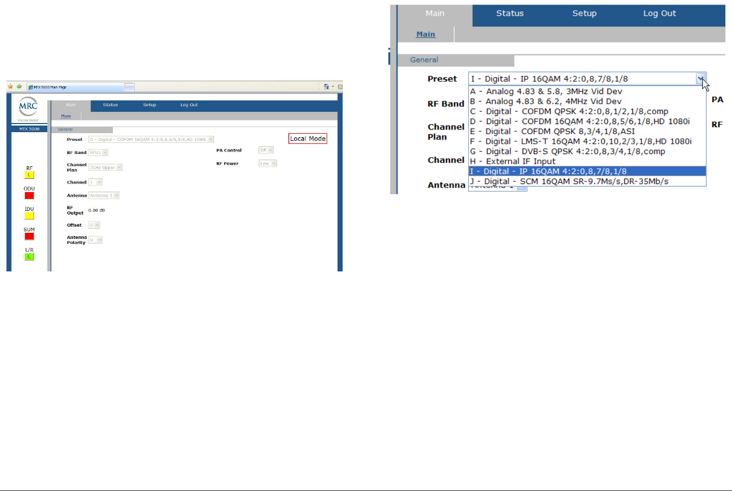
Routine Operation 3-64MTX5000 User and Technical Manual
3.7.3 Remote Configuration Setting Selections
When you interact with the MTX5000 remotely, you will use the
remote screen display (Figure 3-132) Main tab to make
operation option selections.
Figure 3-132: Remote Screen Display - Typical
Option selections are discussed in the following paragraphs.
Option Selections MTX5000 IDU option selections are made
using the Main tab General settings pull-down menus such as
the Preset pull-down menu shown in Figure 3-133. Preset
selection options consist of both factory Presets and custom
Presets.
Figure 3-133: Preset Pull-Down Menu - Typical
Other option pull-down menu selections include RF Band,
Channel Plan, Channel, Antenna, Offset, Antenna Polarity,
PA Control, and RF Power.
Please note that when pull-down menu options, other than the
Preset pull-down menu option, are selected, the change occurs
almost instantaneously. When a new Preset pull-down menu
option is selected, it will take a short time to change all of the
current Preset settings in the IDU.
When a new Preset is selected, a progress bar will be displayed
on the MTX5000 display, the PA Control state will change to Off
if the IDU was transmitting when the new Preset was selected,
and the Reconfiguring Radio. Please Wait... screen will be
displayed. See Figure 3-134 on page 3-65.
If the IDU was transmitting, it may be necessary to select the PA
Control pull-down menu On option to resume transmitting.
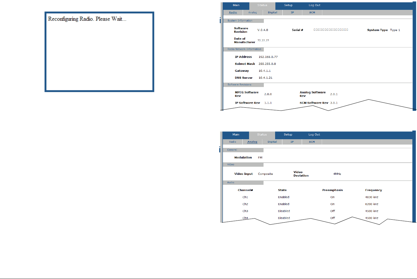
Routine Operation 3-65MTX5000 User and Technical Manual
Figure 3-134: Reconfiguring Radio. Please Wait... Screen -
Typical
Preset Configuration Settings After selecting a new Preset,
the new Preset configuration settings will be displayed on the
Radio, Analog, Digital, or IP tabs, as applicable to the Preset
selected and the licensed options contained in your MTX5000
IDU.
If the Preset selected is analog, the selected Preset information
will be displayed on the Radio tab (Figure 3-135) and on the
Analog tab (Figure 3-136).
Figure 3-135: Radio Tab - Typical
Figure 3-136: Analog Tab - Typical
If the Preset selected is digital or IP, Preset information will be
displayed on the tabs applicable to the Preset selected.
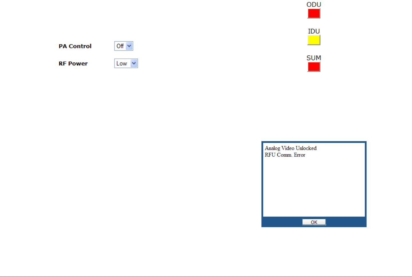
Routine Operation 3-66MTX5000 User and Technical Manual
3.7.4 Transmitter Controls
Control option selections are made using the PA Control and RF
Power pull-down menus. See Figure 3-137.
Figure 3-137: Transmitter Controls Pull-Down Menus
PA Control Pull-Down Menu Selection of the PA Control pull-
down menu options enable or disable the transmitter (On or Off).
RF Power Pull-Down Menu Selection of the RF Power pull-
down menu options allow you to set the power output to Low or
High.
3.7.5 Alerts
The alerts status indicators display the current Outdoor Unit
(ODU), Indoor Unit (IDU), and Summary (SUM) alarms. See
Figure 3-138. If an error exists in either the IDU or ODU, the
status indicators will change from green (no faults) to yellow,
indicating a fault is present that does not affect transmit
operations, or will change to red, indicating a major fault exists
that adversely affects transmit operations.
Figure 3-138: Alert Option Buttons
If one or both of the ODU or IDU status indicators are yellow or
red, the SUM indicator will also reflect yellow or red. Selecting
the applicable option button(s) will display error message
windows applicable to the current faults in the system. See
Figure 3-139.
Figure 3-139: Alert Error Message Window - Typical
Select the OK option button to close the error message window.
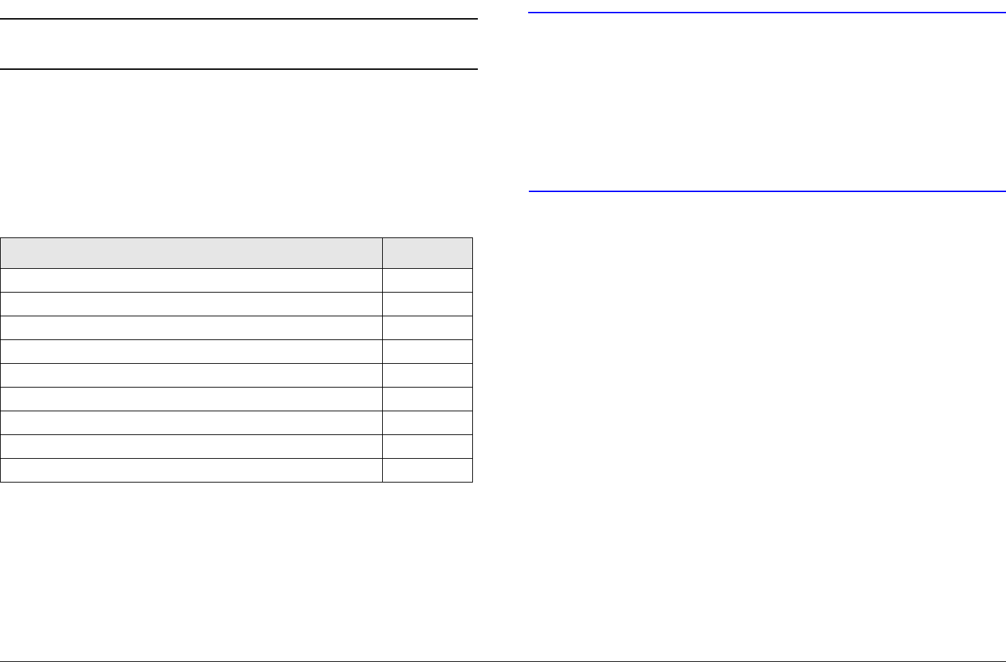
Routine Operation 3-67MTX5000 User and Technical Manual
3.8 Remote Location Operations
Note You must be in the remote operation mode to
perform the following procedures.
Once the MTX5000 system is powered up and has been set for
remote operation per “Select Local/Remote Operation Mode” on
page 3-20, you will be able to check the MTX5000 configuration
and monitor and/or control its operation from a PC at a remote
location.
The procedures required to use the remote screen in the remote
operating mode are as follows:
Topic Page
Select Preset 3-67
Select RF Band and Channel Plan 3-68
Select Operating Channel 3-69
Select Antenna 3-70
Select Frequency Offset 3-70
Select Antenna Polarization 3-70
Enable/Disable Transmitter 3-71
Select High/Low RF Power Mode 3-71
Monitor Alerts 3-72
3.8.1 Select Preset
CAUTION If you select the wrong Preset in the
following steps, wait a minimum of 5
seconds before attempting to select another
Preset.
Failure to wait a minimum of 5 seconds
between selection of Presets may cause
unstable operation.
The procedure required to select a new Preset is contained in
the following steps. You can select a new Preset from a list of 10
factory-configured individual Presets or from up to 99 custom
Presets.
If factory Default Presets were selected locally on the MTX5000
IDU Main screen, only Default Presets may be selected
remotely by the user. If User Presets were selected, only User
Presets may be selected remotely by the user.
When a new Preset is selected in the following steps, the new
Preset will be displayed in the Main tab Preset pull-down menu.
The Preset parameters will also be displayed on the Status tab
Radio, Analog, Digital, and/or IP tabs, as applicable to the
Preset selected, after a short delay.
The PA Control state will also change to Off, if you were
transmitting prior to selecting the new Preset, and it may be
necessary to select the PA Control pull-down menu On option to
resume transmitting.
1. Verify the MTX5000 system is powered up and the
system is in the remote operating mode.
2. Observe the remote screen is displayed on the remote
PC display. See Figure 3-140 on page 3-68.
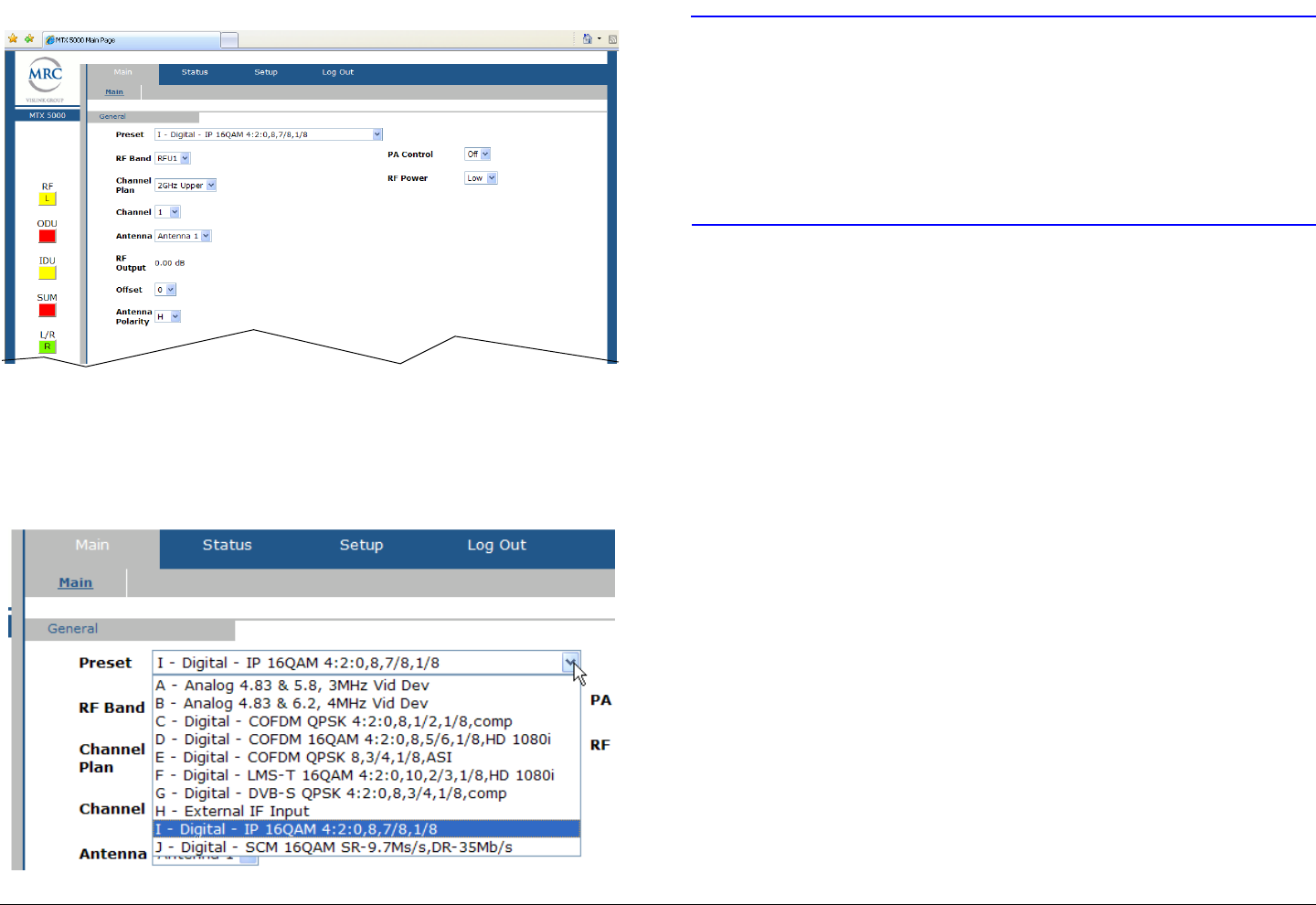
Routine Operation 3-68MTX5000 User and Technical Manual
Figure 3-140: Remote Screen Display - Typical
3. Select the Main tab Preset pull-down menu (Figure 3-
141) and select the Preset required.
Figure 3-141: CONFIGURATION - Preset Pull-Down Menu -
Typical
CAUTION It may take approximately 30 seconds to
change Presets from the remote location.
Do not become impatient during the
configuration process in the following
steps. If you do not allow processing to
complete, software corruption will occur!
4. Observe the Reconfiguring Radio. Please Wait...
window is displayed until the MTX5000 has been re-
configured.
5. Observe the parameters for the selected Preset are
displayed in the Status tab Analog, Digital, and/or IP
tabs, as applicable.
6. Select the Main tab PA Control pull-down menu On
option to resume transmitting, as required.
3.8.2 Select RF Band and Channel Plan
The procedure required to select an RF band (RFU) and a
channel plan from a remote location is contained in the following
steps.
If your MTX5000 system is a dual band configuration, the
procedure required to select the RFU required for dual band
operation is contained in the following steps. This procedure is
also used to select the channel plan required for operation.
In a typical 2 GHz and 7 GHz dual band configuration, the 2 GHz
RF head is typically connected to the IDU RFU 1 rear panel
connector and the 7 GHz RF head is typically connected to the
RFU 2 rear panel connector. The RF heads may, however, be
connected to either rear panel connector. The MTX5000
software automatically detects the RF heads and assigns RFU1
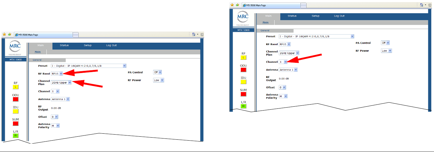
Routine Operation 3-69MTX5000 User and Technical Manual
and RFU2 to the respective RF heads on the RF Band drop-
down menu, as required.
If your MTX5000 system is a single band configuration, the RF
head may be connected to either the IDU RFU 1 or RFU 2 rear
panel connector. The MTX5000 software automatically detects
the RF head configuration and connection and assigns RFU 1 or
RFU 2 to the RF head, as applicable.
When the required RF head is selected, the RF Band pull-down
menu will display the selected RF head.
After selecting the RF head, the Channel Plan pull-down menu
option must be selected. When the Channel Plan pull-down
menu option required is selected, the Channel Plan pull-down
menu will display the selected RF band.
1. Verify the MTX5000 system is powered up and the
system is in the remote operating mode.
2. Observe the remote screen is displayed on the remote
PC display. See Figure 3-142.
Figure 3-142: Remote Screen Display - Typical
3. Select the Main tab RF Band pull-down menu and
select the RFU1 or RFU2 option required.
4. Select the Channel Plan pull-down menu and select
the Channel Plan option required.
3.8.3 Select Operating Channel
The procedure required to select an operating channel is
contained in the following steps. When the Channel pull-down
menu option required is selected, the Channel pull-down menu
will display the selected channel.
1. Verify the MTX5000 system is powered up and the
system is in the remote operating mode.
2. Observe the Remote screen is displayed on the
remote PC display. See Figure 3-143.
Figure 3-143: Remote Screen Display - Typical
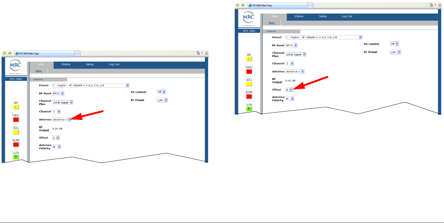
Routine Operation 3-70MTX5000 User and Technical Manual
3. Select the Main tab Channel pull-down menu and
select the Channel pull-down menu option required.
3.8.4 Select Antenna
The procedure required to select the operating antenna is
contained in the following steps. When the Antenna pull-down
menu option is selected, the Antenna pull-down menu will
display the selected antenna.
1. Verify the MTX5000 system is powered up and the
system is in the remote operating mode.
2. Observe the Remote screen is displayed on the
remote PC display. See Figure 3-144.
Figure 3-144: Remote Screen Display - Typical
3. Select the Main tab Antenna pull-down menu and
select the Antenna pull-down menu option required.
3.8.5 Select Frequency Offset
The procedure required to select the operating channel offset is
contained in the following steps. When the Offset pull-down
menu is selected, the Offset pull-down menu will display the
selected channel offset.
1. Verify the MTX5000 system is powered up and the
system is in the remote operating mode.
2. Observe the Remote screen is displayed on the
remote PC display. See Figure 3-145.
Figure 3-145: Remote Screen Display - Typical
3. Select the Main tab Offset pull-down menu and select
the Offset menu option required.
3.8.6 Select Antenna Polarization
The procedure required to select antenna polarization is
contained in the following steps. When the new antenna
polarization is selected, the updated Antenna Polarity pull-
down menu will display the selected antenna.
1. Verify the MTX5000 system is powered up and the
system is in the remote operating mode.
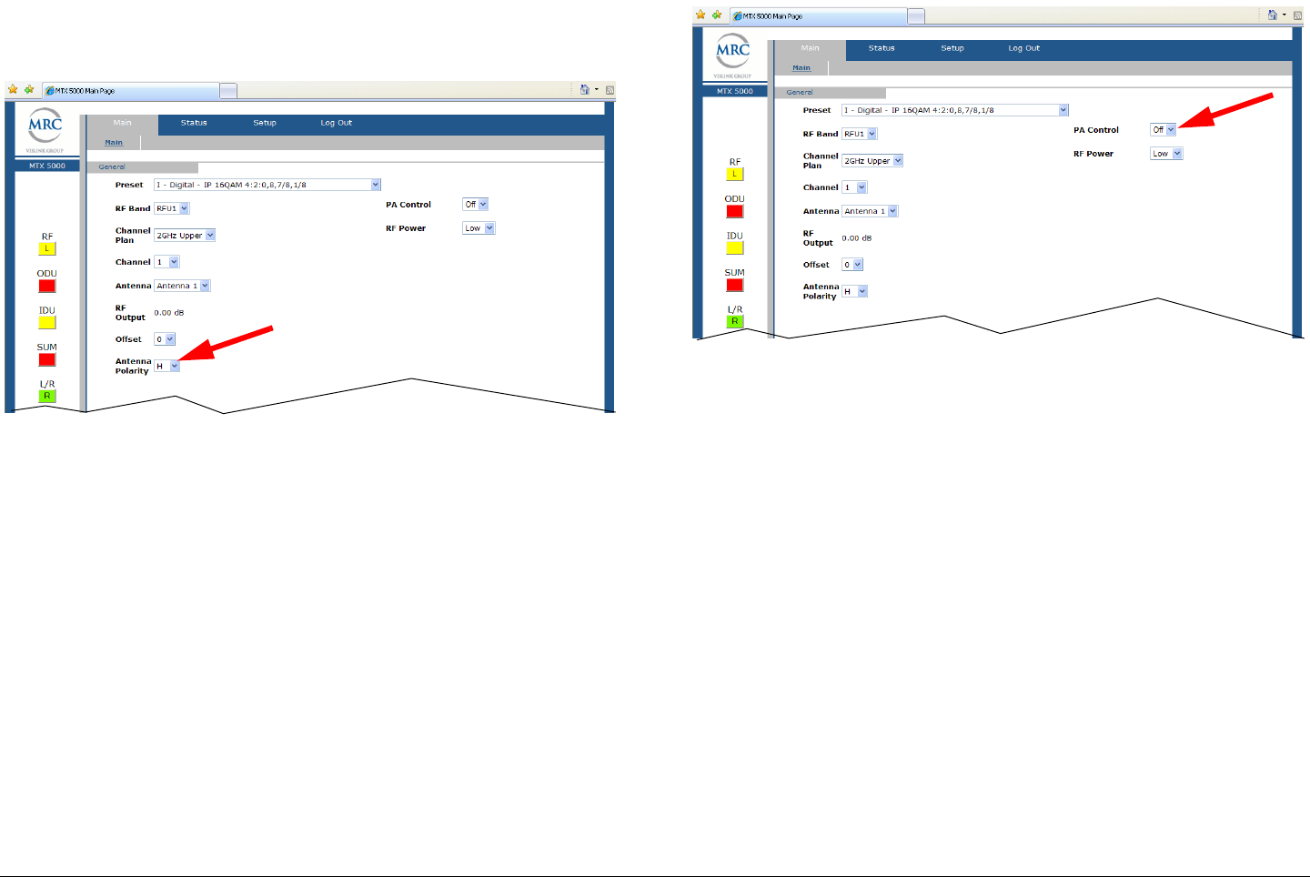
Routine Operation 3-71MTX5000 User and Technical Manual
2. Observe the Remote screen is displayed on the
remote PC display. See Figure 3-146.
Figure 3-146: Remote Screen Display - Typical
3. Select the Main tab Antenna Polarity pull-down
menu and select the Antenna Polarity pull-down
menu option required.
3.8.7 Enable/Disable Transmitter
The procedure required to enable or disable the Power Amplifier
(PA) (transmitter) is contained in the following steps. When the
new power amplifier operating mode is selected, the PA Control
pull-down menu will display the new operating mode.
1. Verify the MTX5000 system is powered up and the
system is in the remote operating mode.
2. Observe the Remote screen is displayed on the
remote PC display. See Figure 3-147.
Figure 3-147: Remote Screen Display - Typical
3. Select the Main tab PA Control pull-down menu and
select the PA Control pull-down menu option
required.
3.8.8 Select High/Low RF Power Mode
The procedure required to select the power amplifier
(transmitter) high or low RF power output is contained in the
following steps. When the power amplifier output power mode is
selected, the RF Power pull-down menu will display the new
operating mode.
1. Verify the MTX5000 system is powered up and the
system is in the remote operating mode.
2. Observe the Remote screen is displayed on the
remote PC display. See Figure 3-148 on page 3-72.
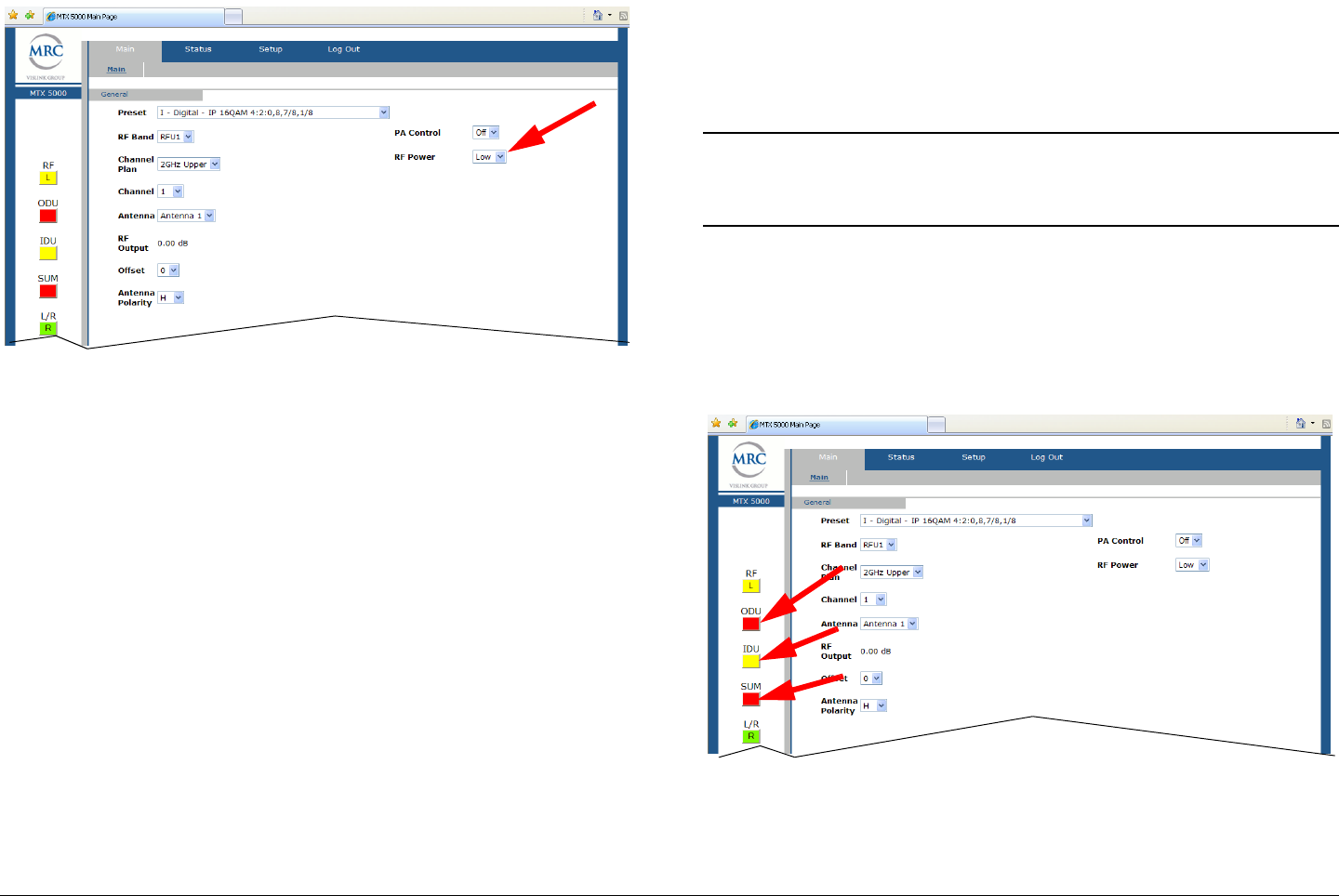
Routine Operation 3-72MTX5000 User and Technical Manual
Figure 3-148: Remote Screen Display - Typical
3. Select the Main tab RF Power pull-down menu and
select the RF Power pull-down menu option required.
3.8.9 Monitor Alerts
The procedure required to monitor the current alarm status of the
ODU, IDU, and summary (SUM) alarms is contained in the
following steps.
The ODU, IDU, and SUM status indicators will be green if no
alarms are present in the system. If a minor IDU and/or ODU
alarm is detected that does not adversely affect transmit
operations, the applicable status indicator will be yellow. If a
major alarm is detected in either the IDU or ODU that adversely
impacts transmit operations, the IDU or ODU status indicators
will be red.
The SUM status indicator will display a red status indicator if the
IDU and/or ODU is reporting at least one major alarm that
adversely affects transmit operations.
The SUM status indicator will not display a red status indicator
for all alarm conditions reported by the ODU or the IDU. Only
alarm conditions that are considered major to the operation of
the transmitter will change the state of the SUM status indicator
status indicator to red.
Note This procedure may be used to select either the
ODU, IDU, or SUM option buttons to review the
current alert status of the MRX5000 System.
1. Verify the MTX5000 system is powered up and the
system is in the remote operating mode.
2. Observe the Remote screen is displayed on the
remote PC display. See Figure 3-149.
Figure 3-149: Remote Screen Display - Typical
3. Observe the ODU, IDU, and SUM status indicators.

Routine Operation 3-73MTX5000 User and Technical Manual
Note In the following step, if no alerts are present, the
No Errors window will be displayed.
If alerts are present, the alerts will be displayed in
the alert window. Refer to the “Error Messages”
section on page 4-1 for a list of possible alarms
and suggested corrective actions.
4. Select the ODU, IDU, or SUM option button, as
required.
- If a green status indicator is selected, a No Errors
window will be displayed.
- If a red or yellow status indicator is selected, an alert
window will be displayed indicating all current alert
messages.
5. When review of the alerts window is complete, select
the OK option button, observe the alerts window
closes, and observe the Remote screen is displayed.
3.9 Routine vs. Advanced Operation
Configuration Settings
The design of the MTX5000 and the internal software makes
commonly available settings accessible from the MTX5000 color
LCD display during routine operations and during advanced
operations.
A summary of settings that can be controlled by each method is
shown in Table 3-2.
Table 3-2: Front Panel vs. Configuration Setting
Parameter Available
Settings Routine
Operation Advanced
Operation
Preset in use • Factory Default
Presets: A thru J
• Custom Presets:
1 thru 99
✔ ✔
Preset text Any alphanumeric
characters
✔
RF Band Dependent upon
system options
✔
Channel Dependent upon
system options:
• 2 GHz Band:
Channels 1 thru
10
• 7 GHz Band:
Channels 1 thru
14
✔
Offset -, 0, or +✔
Antenna • Antenna 1
• Antenna 2
✔
Antenna
Polarity • Horizontal (H)
•Vertical (V)
• Right Circular
(RC)
• Left Circular (LC)
✔
Power
Amplifier (PA)
select mode
•PA Off
•PA On
✔
RF power
select (RF)• Low (L)
• High (H)
✔
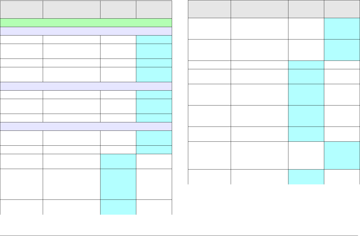
Routine Operation 3-74MTX5000 User and Technical Manual
Radio:
Network Configuration:
Radio IP Enter address ✔
Subnet
Mask Enter address ✔
Gateway Enter address ✔
DNS
Server Enter address ✔
File Network
IP Address Enter address ✔
Subnet
Mask Enter address ✔
Gateway Enter address ✔
Trap Configuration
Destination
Address Enter address ✔
Port # Enter port number ✔
Level Adjust Perform Output
Level Adjust
✔
Color Bars • Off
•On
•A Gen
•A Stby
✔
RF
Calibration Perform PA Voltage
Adjust
✔
Table 3-2: Front Panel vs. Configuration Setting (Continued)
Parameter Available
Settings Routine
Operation Advanced
Operation
License Key Enter alphanumeric
key to activate
licensed option
✔
Change Pwd
(Password) Enter alphanumeric
password, as
required
✔
Time & Date Enter time and date ✔
Diagnostics Perform IDU
diagnostics test
✔
Presets
Option Select factory default
or custom user
Presets
✔
Remote
Control
Option
Select remote control ✔
PA State
Option Select PA off or last
state option
✔
Restore
Presets to
Defaults
Restore all Presets
to factory defaults
(deletes all custom
user Presets)
✔
System Info Review software
revision number
✔
Table 3-2: Front Panel vs. Configuration Setting (Continued)
Parameter Available
Settings Routine
Operation Advanced
Operation
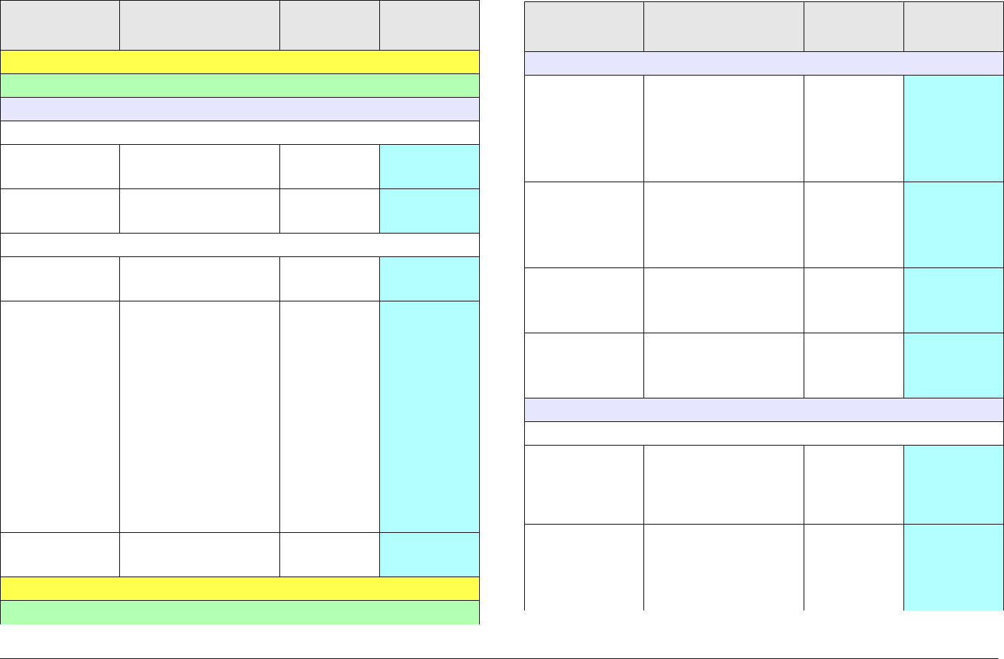
Routine Operation 3-75MTX5000 User and Technical Manual
Analog Presets:
User:
FMT Setup:
Video Deviation
Video
Deviation •3 MHz
•4 MHz
✔
Video Input • Composite
• Baseband
✔
Audio CH1, CH2, CH3, and CH4
Enable • On
•Off
✔
Frequency • 4830 kHz
• 5200 kHz
• 5800 kHz
• 6200 kHz
• 6800 kHz
• 7020 kHz
• 7500 kHz
• 8065 kHz
• 8300 kHz
• 8590 kHz
•Custom
✔
Pre-
Emphasis •On
•Off
✔
Digital COFDM Presets:
User:
Table 3-2: Front Panel vs. Configuration Setting (Continued)
Parameter Available
Settings Routine
Operation Advanced
Operation
COFDM Setup:
FEC • 1/2
•2/3
•3/4
•5/6
•7/8
✔
Guard
Interval •1/32
•1/16
•1/8
•1/4
✔
Constel-
lation • QPSK
• 16-QAM
• 64-QAM
✔
RF B/W • 6 MHz
•7 MHz
•8 MHz
✔
MPEG Setup:
Video In
Input (SD
NTSC
Mode)
•NTSC
• NTSC No
Pedestal
• SDI 525
✔
Input (SD
PAL Mode) •PAL
•PAL-M
•PAL-N
• SDI 625
✔
Table 3-2: Front Panel vs. Configuration Setting (Continued)
Parameter Available
Settings Routine
Operation Advanced
Operation

Routine Operation 3-76MTX5000 User and Technical Manual
Input (HD
Mode) • 720p50
• 720p59
• 720p60
• 1080i25
• 1080i29
• 1080i30
• 1080p24
• 1080p25
• 1080p29
• 1080p30
• 1080psf23
• 1080psf24
• 1080psf25
• 1080psf29
• 1080psf30
✔
Noise
Reduction •On
•Off
✔
SDI Auto
Line •On
•Off
✔
HD Test
Pattern •On
•Off
✔
Audio In
AUDIO 1 and AUDIO 2
Mode • Stereo
• Dual Mono
✔
Table 3-2: Front Panel vs. Configuration Setting (Continued)
Parameter Available
Settings Routine
Operation Advanced
Operation
Standard • Off
• MPEG Layer II
• Linear PCM
• MPEG Layer I
✔
Bit Rate • 128 Kbps
• 160 Kbps
• 192 Kbps
• 224 Kbps
• 256 Kbps
• 320 Kbps
• 384 Kbps
✔
Input • Test Tone
•Analog
•SDI EMB
✔
Balance
(AUDIO 2
Only)
• Unbalanced
• Balanced
✔
Spectrum
Invert •Normal
• Inverted
✔
Encoder
Mode • Standard
• Low Delay
✔
Bit Rate • MP@ML
• 422P@ML
✔
Bit Rate
(Manual) Enter bit rate
required
✔
Table 3-2: Front Panel vs. Configuration Setting (Continued)
Parameter Available
Settings Routine
Operation Advanced
Operation
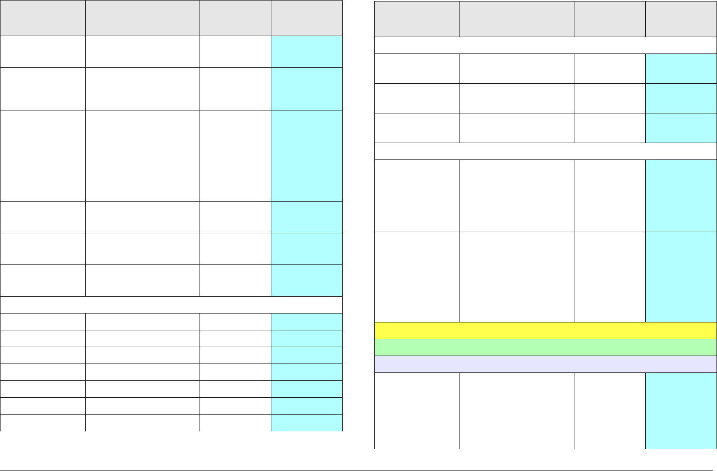
Routine Operation 3-77MTX5000 User and Technical Manual
Bit Rate
Auto •On
•Off
✔
GOP
Length Enter Group of
Pictures (GOP)
length as required
✔
Horiz
Resolution • 720
• 704
• 544
• 528
• 480
• 352
✔
Aspect
Ratio •4:3
• 16:9
✔
PTS per
Picture •On
•Off
✔
VBI • On
•Off
✔
PID Data
Default Select default PIDs ✔
PMT Enter PID required ✔
VIDEO Enter PID required ✔
DATA Enter PID required ✔
AUDIO A Enter PID required ✔
AUDIO B Enter PID required ✔
PCR Enter PID required ✔
Table 3-2: Front Panel vs. Configuration Setting (Continued)
Parameter Available
Settings Routine
Operation Advanced
Operation
Encoding
Service
Name Enter service name ✔
Network
Name Enter network name ✔
EBS/BISS Enable encryption
(license required)
✔
Wayside data
Data
Enable •Off
• TTV Format
• CJM2 Format
• Low Delay
CJM2
✔
Baud Rate • 1200
• 2400
• 4800
• 9600
• 19200
• 38400
✔
Digital ASI Presets:
User:
ASI Setup:
FEC • 1/2
•2/3
•3/4
•5/6
•7/8
✔
Table 3-2: Front Panel vs. Configuration Setting (Continued)
Parameter Available
Settings Routine
Operation Advanced
Operation
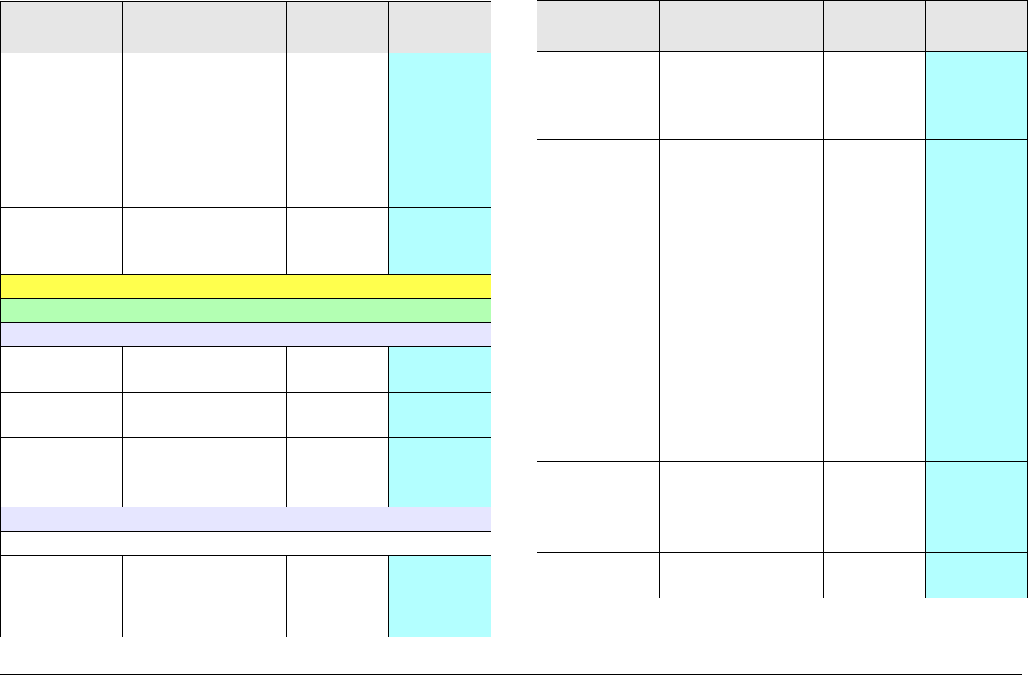
Routine Operation 3-78MTX5000 User and Technical Manual
Guard
Interval •1/32
•1/16
•1/8
•1/4
✔
Constel-
lation • QPSK
• 16-QAM
• 64-QAM
✔
RF B/W • 6 MHZ
•7 MHZ
•8 MHZ
✔
Digital LMS-T Presets:
User:
LMS-T Setup
Constel-
lation • QPSK
• 16-QAM
✔
RF B/W • 10 MHZ
• 20 MHZ
✔
Guard
Interval •1/16
•1/8
✔
FEC • 2/3 ✔
MPEG Setup:
Video In
Input (SD
NTSC
Mode)
•NTSC
•NTSC No
Pedestal
• SDI 525
✔
Table 3-2: Front Panel vs. Configuration Setting (Continued)
Parameter Available
Settings Routine
Operation Advanced
Operation
Input (SD
PAL Mode) •PAL
•PAL-M
•PAL-N
• SDI 625
✔
Input (HD
Mode) • 720p50
• 720p59
• 720p60
• 1080i25
• 1080i29
• 1080i30
• 1080p24
• 1080p25
• 1080p29
• 1080p30
• 1080psf23
• 1080psf24
• 1080psf25
• 1080psf29
• 1080psf30
✔
Noise
Reduction •On
•Off
✔
SDI Auto
Line •On
•Off
✔
HD Test
Pattern •On
•Off
✔
Table 3-2: Front Panel vs. Configuration Setting (Continued)
Parameter Available
Settings Routine
Operation Advanced
Operation
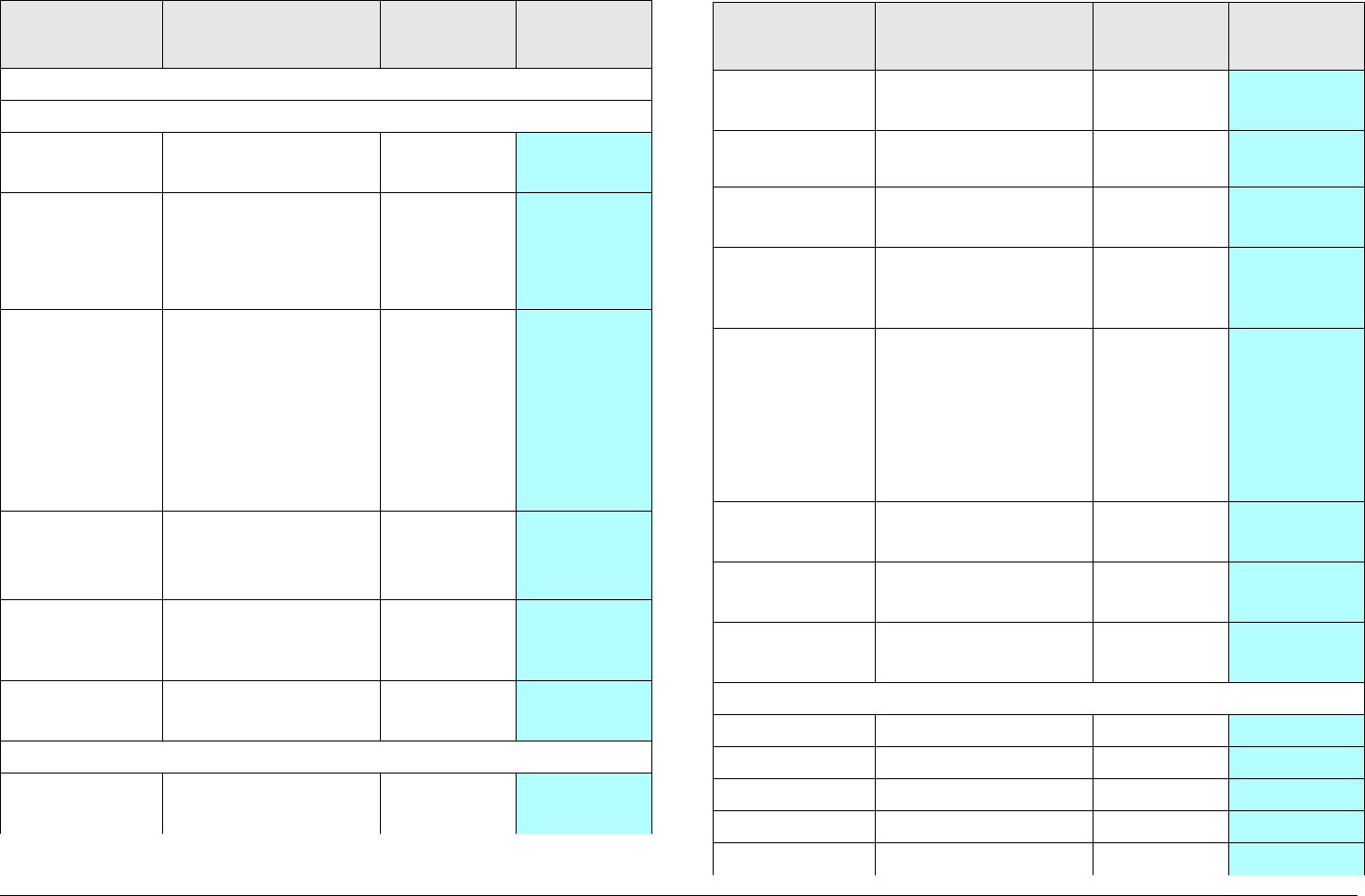
Routine Operation 3-79MTX5000 User and Technical Manual
Audio In
AUDIO 1 and AUDIO 2
Mode • Stereo
• Dual Mono
✔
Standard • Off
• MPEG Layer II
• Linear PCM
• MPEG Layer I
✔
Bit Rate • 128 Kbps
• 160 Kbps
• 192 Kbps
• 224 Kbps
• 256 Kbps
• 320 Kbps
• 384 Kbps
✔
Input • Test Tone
•Analog
•SDI EMB
✔
Balance
(AUDIO 2
only)
• Unbalanced
• Balanced
✔
Spectrum
Invert •Normal
• Inverted
✔
Encoder
Mode • Standard
• Low Delay
✔
Table 3-2: Front Panel vs. Configuration Setting (Continued)
Parameter Available
Settings Routine
Operation Advanced
Operation
Bit Rate • MP@ML
• 422P@ML
✔
Bit Rate
(Manual) Enter bit rate
required
✔
Bit Rate
Auto •On
•Off
✔
GOP
Length Enter Group of
Pictures (GOP)
length as required
✔
Horiz
Resolution • 720
• 704
• 544
• 528
• 480
• 352
✔
Aspect
Ratio •4:3
• 16:9
✔
PTS per
Picture •On
•Off
✔
VBI • On
•Off
✔
PID Data
Default Select default PIDs ✔
PMT Enter PID required ✔
VIDEO Enter PID required ✔
DATA Enter PID required ✔
AUDIO A Enter PID required ✔
Table 3-2: Front Panel vs. Configuration Setting (Continued)
Parameter Available
Settings Routine
Operation Advanced
Operation

Routine Operation 3-80MTX5000 User and Technical Manual
AUDIO B Enter PID required ✔
PCR Enter PID required ✔
Encoding
Service
Name Enter service name ✔
Network
Name Enter network name ✔
EBS/BISS Enable encryption
(license required)
✔
Wayside data
Data
Enable •Off
• TTV Format
• CJM2 Format
• Low Delay
CJM2
✔
Baud Rate • 1200
• 2400
• 4800
• 9600
• 19200
• 38400
✔
Table 3-2: Front Panel vs. Configuration Setting (Continued)
Parameter Available
Settings Routine
Operation Advanced
Operation
Digital DVB-S Presets
User:
COFDM Setup:
FEC • 1/2
•2/3
•3/4
•5/6
•7/8
✔
Guard
Interval •1/32
•1/16
•1/8
•1/4
✔
Constel-
lation • QPSK
• 16-QAM
• 64-QAM
✔
RF B/W • 6 MHz
•7 MHz
•8 MHz
✔
DVB-S Setup:
DVBS Roll
Off • 20%
• 25%
• 35%
✔
Table 3-2: Front Panel vs. Configuration Setting (Continued)
Parameter Available
Settings Routine
Operation Advanced
Operation

Routine Operation 3-81MTX5000 User and Technical Manual
MPEG Setup:
Video In
Input (SD
NTSC
Mode)
•NTSC
•NTSC No
Pedestal
• SDI 525
✔
Input (SD
PAL Mode) •PAL
•PAL-M
•PAL-N
• SDI 625
✔
Input (HD
Mode) • 720p50
• 720p59
• 720p60
• 1080i25
• 1080i29
• 1080i30
• 1080p24
• 1080p25
• 1080p29
• 1080p30
• 1080psf23
• 1080psf24
• 1080psf25
• 1080psf29
• 1080psf30
✔
Noise
Reduction •On
•Off
✔
Table 3-2: Front Panel vs. Configuration Setting (Continued)
Parameter Available
Settings Routine
Operation Advanced
Operation
SDI Auto
Line •On
•Off
✔
HD Test
Pattern •On
•Off
✔
Audio In
AUDIO 1 and AUDIO 2
Mode • Stereo
• Dual Mono
✔
Standard • Off
• MPEG Layer II
• Linear PCM
• MPEG Layer I
✔
Bit Rate • 128 Kbps
• 160 Kbps
• 192 Kbps
• 224 Kbps
• 256 Kbps
• 320 Kbps
• 384 Kbps
✔
Input • Test Tone
•Analog
•SDI EMB
✔
Balance
(AUDIO 2
only)
• Unbalanced
• Balanced
✔
Spectrum
Invert •Normal
• Inverted
✔
Table 3-2: Front Panel vs. Configuration Setting (Continued)
Parameter Available
Settings Routine
Operation Advanced
Operation

Routine Operation 3-82MTX5000 User and Technical Manual
Encoder
Mode • Standard
• Low Delay
✔
Bit Rate • MP@ML
• 422P@ML
✔
Bit Rate
(Manual) Enter bit rate
required
✔
Bit Rate
Auto •On
•Off
✔
GOP
Length Enter Group of
Pictures (GOP)
length as required
✔
Horiz
Resolution • 720
• 704
• 544
• 528
• 480
• 352
✔
Aspect
Ratio •4:3
• 16:9
✔
PTS per
Picture •On
•Off
✔
VBI • On
•Off
✔
PID Data
Default Select default PIDs ✔
PMT Enter PID required ✔
Table 3-2: Front Panel vs. Configuration Setting (Continued)
Parameter Available
Settings Routine
Operation Advanced
Operation
VIDEO Enter PID required ✔
DATA Enter PID required ✔
AUDIO A Enter PID required ✔
AUDIO B Enter PID required ✔
PCR Enter PID required ✔
Encoding
Service
Name Enter service name ✔
Network
Name Enter network name ✔
EBS/BISS Enable encryption
(license required)
✔
Wayside data
Data
Enable •Off
• TTV Format
• CJM2 Format
• Low Delay
CJM2
✔
Baud Rate • 1200
• 2400
• 4800
• 9600
• 19200
• 38400
✔
Table 3-2: Front Panel vs. Configuration Setting (Continued)
Parameter Available
Settings Routine
Operation Advanced
Operation

Routine Operation 3-83MTX5000 User and Technical Manual
Digital IP Presets:
User:
IP Setup:
IP Config
FEC • 1/2
•2/3
•3/4
•5/6
•7/8
✔
Guard
Interval •1/32
•1/16
•1/8
•1/4
✔
Constel-
lation • QPSK
• 16-QAM
• 64-QAM
✔
RF B/W • 6 MHZ
•7 MHZ
•8 MHz
✔
IP Setup
IP Transfer
Mode •IP Only
•IP + Video
✔
Video
Bitrate Enter bit rate
required
✔
Table 3-2: Front Panel vs. Configuration Setting (Continued)
Parameter Available
Settings Routine
Operation Advanced
Operation
MPEG Setup:
Video In
Input (SD
NTSC
Mode)
•NTSC
• NTSC No
Pedestal
• SDI 525
✔
Input (SD
PAL Mode) •PAL
•PAL-M
•PAL-N
• SDI 625
✔
Input (HD
Mode) • 720p50
• 720p59
• 720p60
• 1080i25
• 1080i29
• 1080i30
• 1080p24
• 1080p25
• 1080p29
• 1080p30
• 1080psf23
• 1080psf24
• 1080psf25
• 1080psf29
• 1080psf30
✔
Noise
Reduction •On
•Off
✔
Table 3-2: Front Panel vs. Configuration Setting (Continued)
Parameter Available
Settings Routine
Operation Advanced
Operation

Routine Operation 3-84MTX5000 User and Technical Manual
SDI Auto
Line •On
•Off
✔
HD Test
Pattern •On
•Off
✔
Audio In
AUDIO 1 and AUDIO 2
Mode • Stereo
• Dual Mono
✔
Standard • Off
• MPEG Layer II
• Linear PCM
• MPEG Layer I
✔
Bit Rate • 128 Kbps
• 160 Kbps
• 192 Kbps
• 224 Kbps
• 256 Kbps
• 320 Kbps
• 384 Kbps
✔
Input • Test Tone
•Analog
•SDI EMB
✔
Balance
(AUDIO 2
only)
• Unbalanced
• Balanced
Spectrum
Invert •Normal
• Inverted
✔
Table 3-2: Front Panel vs. Configuration Setting (Continued)
Parameter Available
Settings Routine
Operation Advanced
Operation
Encoder
Mode • Standard
• Low Delay
✔
Bit Rate • MP@ML
• 422P@ML
✔
Bit Rate
(Manual) Enter bit rate
required
✔
Bit Rate
Auto •On
•Off
✔
GOP
Length Enter Group of
Pictures (GOP)
length as required
✔
Horiz
Resolution • 720
• 704
• 544
• 528
• 480
• 352
✔
Aspect
Ratio •4:3
• 16:9
✔
PTS per
Picture •On
•Off
✔
VBI • On
•Off
✔
PID Data
Default Select default PIDs ✔
PMT Enter PID required ✔
Table 3-2: Front Panel vs. Configuration Setting (Continued)
Parameter Available
Settings Routine
Operation Advanced
Operation
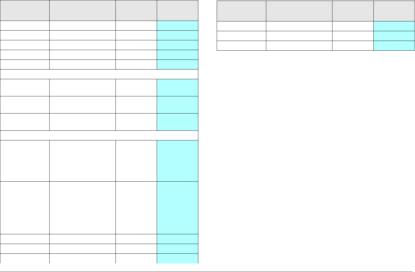
Routine Operation 3-85MTX5000 User and Technical Manual
VIDEO Enter PID required ✔
DATA Enter PID required ✔
AUDIO A Enter PID required ✔
AUDIO B Enter PID required ✔
PCR Enter PID required ✔
Encoding
Service
Name Enter service name ✔
Network
Name Enter network name ✔
EBS/BISS Enable encryption
(license required)
✔
Wayside data
Data
Enable •Off
• TTV Format
• CJM2 Format
• Low Delay
CJM2
✔
Baud Rate • 1200
• 2400
• 4800
• 9600
• 19200
• 38400
✔
PMT Enter PID required ✔
VIDEO Enter PID required ✔
DATA Enter PID required ✔
Table 3-2: Front Panel vs. Configuration Setting (Continued)
Parameter Available
Settings Routine
Operation Advanced
Operation
AUDIO A Enter PID required ✔
AUDIO B Enter PID required ✔
PCR Enter PID required ✔
Table 3-2: Front Panel vs. Configuration Setting (Continued)
Parameter Available
Settings Routine
Operation Advanced
Operation

Routine Operation 3-86MTX5000 User and Technical Manual
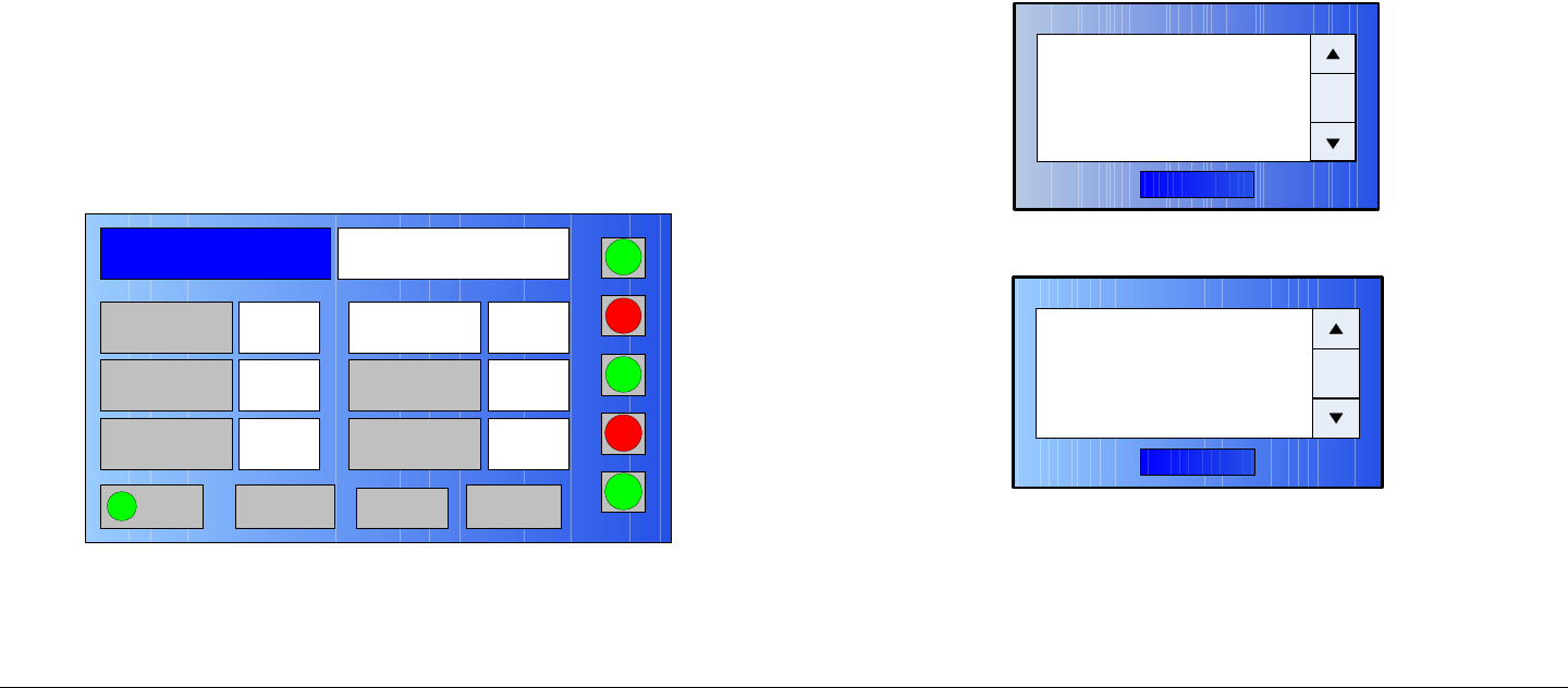
4
Troubleshooting 4-1MTX5000 User and Technical Manual
Troubleshooting
4.1 Chapter Overview
This chapter describes how to troubleshoot your MTX5000
Transmitter System (MTX5000).
4.2 Error Messages
The MTX5000 has a library of diagnostic error messages to help
you pinpoint any problems.
Errors detected during normal operation of the MTX5000 system
will cause the MTX5000 Indoor Unit (IDU) color LCD display
panel Main screen ODU, IDU, or SUM status indicators to turn
yellow or red, alerting you to investigate the problem. See
Figure 4-1.
Figure 4-1: Color LCD Display Panel - Typical
Red ODU, IDU, or SUM status indicators indicate at least one
major fault is present that adversely effects transmit operation.
Yellow status indicators indicate a minor fault is present that does
Channel 1 0Offset
Antenna Ant. Pol.Direct V
RFU2
7L
RF Band
Preset 1 Analog
4.83 & 5.8, 3MHz Vid Dev
RF Output XX
dBm
<- Status Setup Status ->
PA On
SUM
ODU
IDU
RF
L/R
H
L
not impact transmit operations. Green status indicators indicate
no faults are present.
The applicable ODU, IDU, or SUM status button must be
selected using the IDU color LCD display panel touch screen or
front panel function keys and SEL key to view the error
messages.
The error messages are displayed on the MTX5000 color LCD
display screen ODU Status, IDU Status, or Summary Alarm
dialog boxes. See Figure 4-2, Figure 4-3, and Figure 4-4 on
page 4-2.
Figure 4-2: ODU Status Dialog Box - Typical
Figure 4-3: IDU Status Dialog Box - Typical
OK
ODU Status
xxxxxxxxxxx
OK
IDU Status
xxxxxxxxxxxxxxxxx
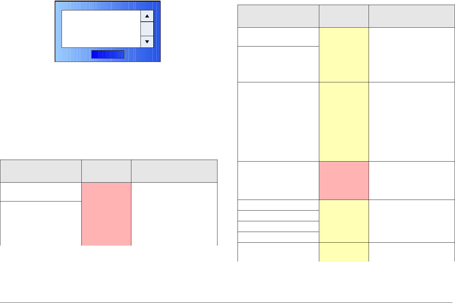
Troubleshooting 4-2MTX5000 User and Technical Manual
Figure 4-4: Summary Alarm Dialog Box - Typical
In all cases, the error message will uniquely identify the problem,
i.e., +5.5V Powersupply Error.
To isolate possible IDU problems, see “Perform IDU Diagnostics”
on page 3-56.
See Table 4-1 for a list of Indoor Unit (IDU) error messages and
what to do when they appear.
Table 4-1: IDU Error Messages
Error Message Error Type Suggested Technical
Staff Action
+5.5V Powersupply
Error Major • Indicates internal
power supply failure
and potential unstable
operation. Verify IDU
input power.
• Call MRC Technical
Support.
+12V Powersupply
Error
OK
Summary Alarm
xxxxxxxxxxxxxxxxx
+24V Powersupply
Error Minor • Indicates minor
internal power supply
failure. Verify IDU
input power.
• Call MRC Technical
Support.
-12V Powersupply Error
Ext IF Level Too High Minor • Indicates external IF
level is above
recommended level.
Attenuate or
disconnect signal to
avoid system
damage.
• Call MRC Technical
Support.
FMT Fault Alarm Major • Indicates internal
hardware fault.
• Call MRC Technical
Support.
Audio1 Unlocked Minor Verify audio input is
connected
Audio2 Unlocked
Audio3 Unlocked
Audio4 Unlocked
Analog Video Unlocked Minor Verify composite video
input is connected.
Table 4-1: IDU Error Messages
Error Message Error Type Suggested Technical
Staff Action
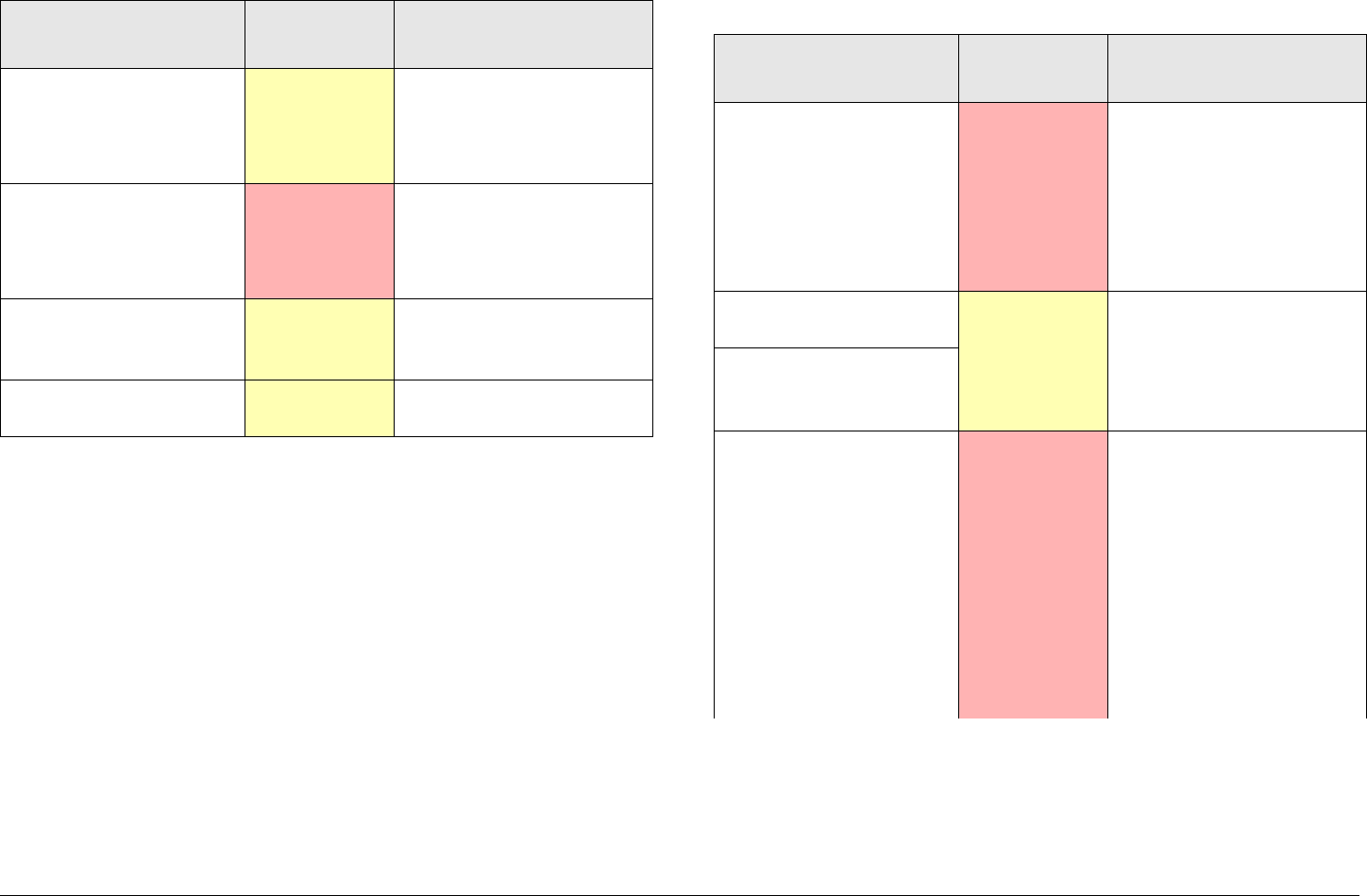
Troubleshooting 4-3MTX5000 User and Technical Manual
See Table 4-2 for a list of Outdoor Unit (ODU) error messages
and what to do when they appear.
Audio Modulator Fault Minor • Indicates internal
hardware fault.
• Call MRC Technical
Support.
Digital Modulator Fault Major • Indicates internal
hardware fault.
• Call MRC Technical
Support.
Digital Mod. Transport
Unlocked Minor May indicate internal
hardware fault or invalid
input.
Digital Mod. Video
Unlocked Minor Verify input video
connection.
Table 4-1: IDU Error Messages
Error Message Error Type Suggested Technical
Staff Action
Table 4-2: ODU Error Messages
Error Message Error Type Suggested Technical
Staff Action
+15V Powersupply
Error Major • Indicates internal
power supply failure
and potential unstable
operation. Verify IDU
input power.
• Call MRC Technical
Support.
+12V Powersupply
Error Minor • Indicates ODU power
supply failure. Verify
ODU cabling.
• Call MRC Technical
Support.
+11V Powersupply
Error
RFU Comm. Error Major • Indicates a
communication error
between the IDU and
ODU. Verify DC
power is being
supplied to the ODU
and verify RF cable
connection between
the IDU and ODU.
• Call MRC Technical
Support.

Troubleshooting 4-4MTX5000 User and Technical Manual
4.3 Ethernet Connections
If you are connected to the Ethernet via the IDU rear panel
ETHERNET RJ45 connector and you find that the color LCD
display panel appears to be operating very slowly or has locked
up completely, disconnect the Ethernet cable from the
ETHERNET connector.
This should free up the color LCD display Panel and the IDU
should resume operating properly.
Transmit Power Low Major • If error persists for
more than 10
seconds, verify
cabling between IDU
and ODU. If in
External IF operating
mode, verify 70 MHz
input is properly
connected.
• Call MRC Technical
Support.
RFU UHF Unlocked Minor • Indicates RF circuitry
is unlocked. Wait 5-
10 seconds and error
should clear.
• Call MRC Technical
Support.
RFU Synth. Unlocked
Table 4-2: ODU Error Messages
Error Message Error Type Suggested Technical
Staff Action
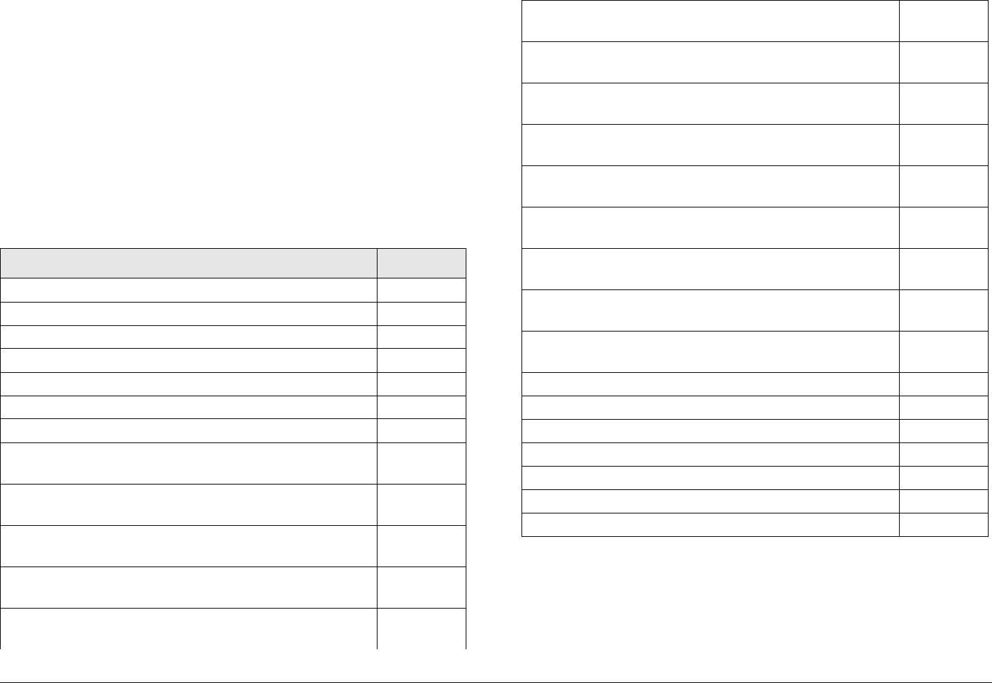
5
Advanced Operations 5-1MTX5000 User and Technical Manual
Advanced Operations
5.1 Chapter Overview
This chapter describes how to use the software contained in the
MTX5000 to provide password control of advanced operations,
to create or update Preset settings in the Local or Remote mode,
to set an Internet Protocol (IP) address for remote operations,
and to update the MTX5000 software. This information is
provided and intended for use by the technical staff.
Here are the topics covered:
Topic Page
Before You Begin 5-1
MTX5000 5-2
Software 5-2
Settings 5-2
System Rules 5-2
Configuration Settings 5-3
Local Mode Password Control 5-3
Create or Update Preset Configuration Settings in
Local Mode 5-6
Create or Update Custom Analog Preset
Configuration In Local Mode 5-7
Create or Update Digital COFDM Preset
Configuration Settings in Local Mode 5-17
Create or Update Digital ASI Preset
Configuration Settings in Local Mode 5-30
Create or Update Digital LMS-T Preset
Configuration Settings in Local Mode 5-34
5.2 Before You Begin
Before you begin, you should review the following topics.
Create or Update Digital DVB-S Preset
Configuration Settings in Local Mode 5-47
Create or Update Digital IP Preset
Configuration Settings in Local Mode 5-60
Create or Update Preset Configuration Settings in
Remote Mode 5-73
Create or Update Custom Analog Preset
Configuration in Remote Mode 5-73
Create or Update Custom Digital COFDM
Preset Configuration in Remote Mode 5-77
Create or Update Custom Digital ASI Preset
Configuration in Remote Mode 5-82
Create or Update Custom Digital LMS-T Preset
Configuration in Remote Mode 5-86
Create or Update Custom Digital DVB-S Preset
Configuration in Remote Mode 5-91
Create or Update Custom Digital IP Preset
Configuration in Remote Mode 5-96
Preset File Management 5-101
Restore Presets to Defaults 5-102
Save Preset Configurations to a File 5-104
Load Preset Configurations from a File 5-106
Set Network Addresses for Remote Operation 5-114
Firmware Update 5-114
License Manager 5-117

Advanced Operations 5-2MTX5000 User and Technical Manual
5.2.1 MTX5000
The procedures described in this chapter assume you already
know how to operate your MTX5000. If this is not the case,
please review the information presented in the following
Chapters of this manual:
“Introduction” Chapter on page 1-1
“Product Description” Chapter on page 2-1
“Routine Operation” Chapter on page 3-1
5.2.2 Software
This chapter assumes the MTX5000 software is operating
properly on your MTX5000 and that you are familiar with the
MTX5000 color LCD display panel screens, touch panel, and
function keys. You must also be familiar with both Local and
Remote operations.
5.2.3 Settings
Before beginning to create, modify, or program a Preset
configuration or channel plan into your MTX5000, you must
define what settings are required.
5.2.4 System Rules
The IDU does not need to be removed from its rack-mounted
position to perform these procedures. The procedures can be
performed when the IDU is installed in its normal rack-mounted
position.
It is important, however, that the MTX5000 must not be
transmitting when these procedures are performed.
When performing procedures contained in this Chapter, you
must observe the following CAUTIONS to avoid corrupting
software.
CAUTION Do not power down the MTX5000 system
when the software update progress bar is
displayed, as the software update can
become corrupted.
CAUTION Do not attempt to perform IDU software
updates or make changes to Preset settings
while the MTX5000 system is actively
transmitting.
Attempts to program software updates or
make changes to Preset settings into the
IDU when the system is transmitting will
interrupt broadcast operations and may
corrupt the software.
CAUTION Avoid damage to the color LCD display
panel!
The color LCD display panel touch screen
may be damaged if a sharp, hard-pointed
object, such as a pencil or a pen, is used to
select the displayed options.
Touch screen options must only be selected
using your fingers, a soft-pointed stylus, or
the front panel function keys.

Advanced Operations 5-3MTX5000 User and Technical Manual
Damage to the color LCD display panel
caused by using a hard-pointed object or
other misuse may void your warranty on
the MTX5000 IDU.
When configuring your MTX5000 IDU, the following rules must
be observed:
• You can only select configuration settings applicable
to the hardware configuration and the licensed
options contained in your MTX5000 IDU.
• The MTX5000 IDU must not be placed in the transmit
mode when performing any procedures contained in
this Chapter.
5.2.5 Configuration Settings
New configuration settings can be prepared from scratch using
an existing factory default Preset or from a custom user Preset.
The factory default Presets and your custom user Presets must
be used as “make-froms” to prepare any new Preset from
scratch. Preset configuration settings may be prepared in either
the Local or Remote operating mode. Other advanced
operations must be performed in the Local mode only. Custom
user Presets can also be modified, as required.
Your MTX5000 IDU was delivered with 10 factory default
Presets. The factory default Presets cannot be changed or
deleted from your IDU. When preparing a new Preset, you must
first select a Preset to be used as a “make-from” to prepare the
new Preset configuration. If a factory Preset is inactive, the
licensed option is not contained in your IDU.
If you are preparing a new Preset configuration in the Local
mode and the licensed option is not contained in your IDU, the
option will be inactive (greyed-out) on the IDU color LCD display.
If you are preparing a new Preset in the Remote mode and the
licensed option is not contained in your IDU, a message window
indicating This preset cannot be selected. will be displayed on
the remote PC display. Only licensed options contained in your
IDU may be used to prepare new custom user Presets.
Once a Preset configuration is created or changed, it should be
saved. The IDU will remember the last operating state, but there
is no guarantee that it will remember the state unless the Preset
configuration settings are saved into the Preset list. The steps
required to save the settings are contained in the applicable
procedures.
5.3 Local Mode Password Control
CAUTION Avoid damage to the color LCD display
panel!
The color LCD display panel touch screen
may be damaged if a sharp, hard-pointed
object, such as a pencil or a pen, is used to
select the displayed options.
Touch screen options must only be selected
using your fingers, a soft-pointed stylus, or
the front panel function keys.
Damage to the color LCD display panel
caused by using a hard-pointed object or
other misuse may void your warranty on
the MTX5000 IDU.
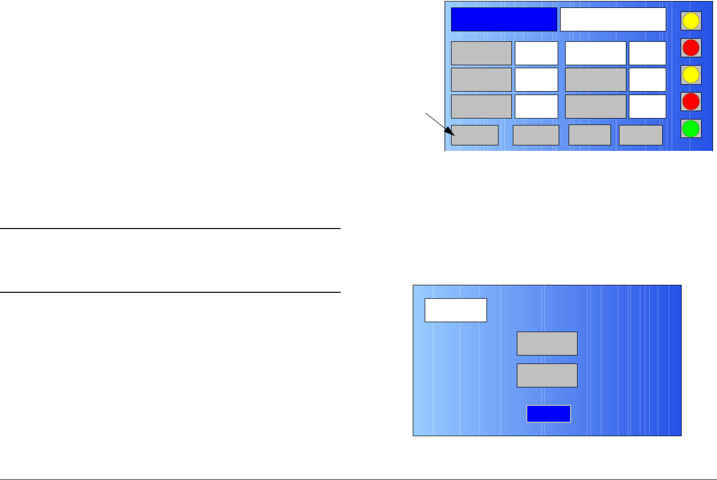
Advanced Operations 5-4MTX5000 User and Technical Manual
The MTX5000 IDU provides password control of the system to
prevent unauthorized personnel from making changes to Preset
settings. Local mode password control of the system may only
be performed with the MTX5000 IDU in the Local mode of
operation.
All passwords are case-sensitive. The MTX5000 IDU is
delivered with a default password. When your IDU is received
from the factory, the default password is PASSWORD.
The default password should be changed to your own personal
password upon receipt of the MTX5000 System. Your new
password should be recorded and should be maintained in a
secure location.
The procedure required to change the default or current
password to another password of your choice is contained in the
following steps.
Note In the following steps, the color LCD display option
buttons and pull-down menu options may be
selected using either the touch screen or the
function keys and the SEL key.
1. Verify the MTX5000 IDU is powered up. See
”Powering the MTX5000 System” on page 3-7.
2. Observe the Main screen is displayed. See Figure 5-
1.
Figure 5-1: Main Screen - Typical
3. Select the Main screen PA operation button for PA
Off, as required.
4. Select the L/R option button for L (local mode), as
required.
5. Select the Setup option button and observe the Setup
screen is displayed. See Figure 5-2.
Figure 5-2: Setup Screen
Channel 1 0Offset
Antenna Ant. Pol.Antenna1 H
RFU1
No RF
RF Band
Preset A Analog
4.83 & 5.8, 3MHz Vid Dev
RF Output XX
dBm
<- Status Setup Status ->
PA Off
SUM
ODU
IDU
RF
L/R
L
L
PA
Operation
Button
Setup
User
Main
Radio
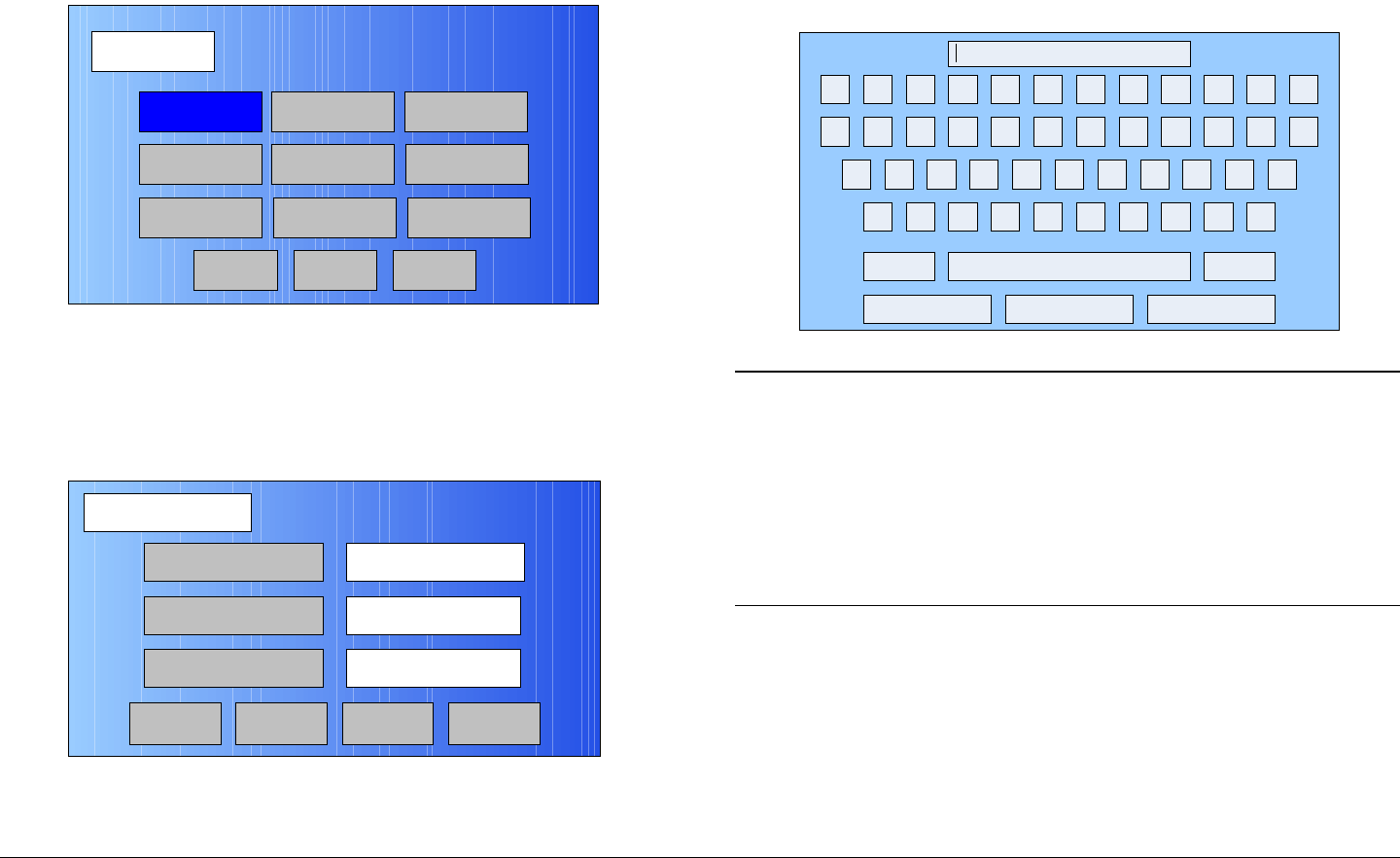
Advanced Operations 5-5MTX5000 User and Technical Manual
6. Select the Radio option button and observe the Radio
screen is displayed. See Figure 5-3.
Figure 5-3: Radio Screen
7. Select the Change Pwd option button and observe the
Change Password screen is displayed. See
Figure 5-4.
Figure 5-4: Change Password Screen
Radio
Back
Network Config Level Adjust Color Bars
Calibration
Time & Date
Change Pwd
System Info
License Key
Diagnostics
Next
Main
Change Password
Accept
Enter Old Password
Enter Password
Clear Cancel
Re-Enter Password
Main
8. Select the Enter Old Password option button and
observe the keyboard screen is displayed. See
Figure 5-5.
Figure 5-5: Keyboard Screen
Notes When entering passwords in the following steps,
the password is case-sensitive. Passwords may
consist of from 1 to 15 alphanumeric characters.
If any errors are made when entering a password,
an error message will be displayed in the keyboard
screen text box. Select the keyboard Clear key
and re-enter the correct password.
9. Enter the old password, select the Enter key, and
observe the Change Password screen is displayed.
See Figure 5-6 on page 5-6.
! @ # $ % ^ & * ( ) _ +
Q W E R T Y U I O P { }
A S D F G H J K L :
Z X C V B N M < > ?
Shift BS
Clear CancelEnter
“

Advanced Operations 5-6MTX5000 User and Technical Manual
Figure 5-6: Change Password Screen
10. Observe the Enter Password option button is active,
select the Enter Password option button, and
observe the keyboard screen is displayed.
11. Enter your new password, select the Enter key, and
observe the Change Password screen is displayed.
12. Select the Re-enter Password option button, and
observe the keyboard screen is displayed.
13. Re-enter your new password, select the Enter key,
and observe the Change Password screen is
displayed.
14. Select the Accept option button and observe the
Radio screen is displayed.
15. Select the Main option button and observe the Main
screen is displayed.
Change Password
Accept
Enter Old Password Test
Enter Password
Clear Cancel
Re-enter Password
Main
5.4 Create or Update Preset
Configuration Settings in Local Mode
CAUTION Avoid damage to the color LCD display
panel when performing the following
procedures!
The color LCD display panel touch screen
may be damaged if a sharp, hard-pointed
object, such as a pencil or a pen, is used to
select the displayed options.
Touch screen options must only be selected
using your fingers, a soft-pointed stylus, or
the front panel function keys.
Damage to the color LCD display panel
caused by using a hard-pointed object or
other misuse may void your warranty on
the MTX5000 IDU.
The procedures required to create or update Preset
configuration settings in the Local mode are contained in the
following paragraphs. Preset configuration settings may be
created or updated for the following types of Presets:
• Analog FMT Presets
• Digital COFDM Presets
• Digital ASI Presets
• Digital LMS-T Presets

Advanced Operations 5-7MTX5000 User and Technical Manual
• Digital DVB-S Presets
• Digital IP Presets.
Please note that an External IF In Preset is also available for
normal operation using the factory default External IF In
Preset, but no configuration settings may be made to this
Preset. No procedures are therefore applicable or are provided
in this chapter for External IF In Presets.
5.4.1 Create or Update Custom Analog Preset
Configuration In Local Mode
The procedure required to create a new custom analog Preset
configuration or to update an existing Preset configuration is
contained in the following steps.
When preparing a new analog Preset, you must first select an
existing analog Preset from either one of the analog factory
default Presets or from your custom user analog Presets. The
selected Preset will be used as a “make-from” to prepare the
new analog Preset configuration.
Please note that while factory default analog Presets may be
used to prepare a new Preset configuration, these factory
default Presets cannot be changed or deleted. They can only
be used as “make-froms”.
When the new configuration is prepared using the factory default
Preset, it cannot be saved with the factory Preset number or
Preset name. A new Preset number and Preset name must be
assigned to the new Preset.
When using a custom Preset as a “make-from”, the new Preset
should be saved with a new Preset number. When you save the
new Preset, the Preset number will automatically be increased to
the next available Preset number.
If you select an existing Preset number when saving the new
Preset, the original custom Preset will be overwritten and cannot
be recovered. The only way to restore a Preset that has been
overwritten is to re-enter the custom Preset data from scratch.
If you are updating configuration settings on an existing custom
user Preset, when you save the configuration settings, the
Preset number will automatically be increased to the next
available Preset number. You must enter and save the
configuration settings using the original Preset number.
Note In the following steps, the color LCD display option
buttons and pull-down menu options may be
selected using either the touch screen or the
function keys and the SEL key.
1. Verify the MTX5000 IDU is powered up. See
”Powering the MTX5000 System” on page 3-7.
2. Observe the Main screen is displayed. See Figure 5-
7.
Figure 5-7: Main Screen - Typical
Channel 1 0Offset
Antenna Ant. Pol.Antenna1 H
RFU1
No RF
RF Band
Preset A Analog
4.83 & 5.8, 3MHz Vid Dev
RF Output XX
dBm
<- Status Setup Status ->
PA Off
SUM
ODU
IDU
RF
L/R
L
L
PA
Operation
Button
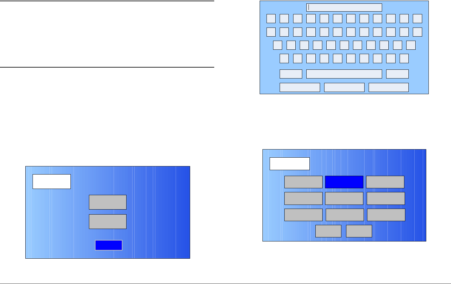
Advanced Operations 5-8MTX5000 User and Technical Manual
3. Select the L/R option button for L (local mode), as
required.
Notes If you are updating an existing analog Preset
configuration, select the Preset to be updated in
the following step.
If you are creating a new analog Preset
configuration, any analog Preset may be selected
in the following step.
4. Perform “Select Preset” on page 3-24 to select the
analog Preset required to be updated or to be used as
a “make-from”.
5. Select the Main screen PA operation button for PA
Off, as required.
6. Select the Main screen Setup option button and
observe the Setup screen is displayed. See Figure 5-
8.
Figure 5-8: Setup Screen
7. Select the User option button and observe the
Setup
User
Main
Radio
keyboard screen is displayed. See Figure 5-9.
Figure 5-9: Keyboard Screen
8. Enter your password, select the Enter key, and
observe the Operation Mode screen is displayed.
See Figure 5-10.
Figure 5-10: Operation Mode Screen
9. Select the FMT option button and observe the FMT
SETUP screen is displayed. See Figure 5-11 on
page 5-9.
! @ # $ % ^ & * ( ) _ +
Q W E R T Y U I O P { }
A S D F G H J K L :
Z X C V B N M < > ?
Shift BS
Clear CancelEnter
“
Operation Mode
Back
COFDM FMT ASI
IP
SCM
LMS-T
Save As Preset
DVBS
MPEG
Main
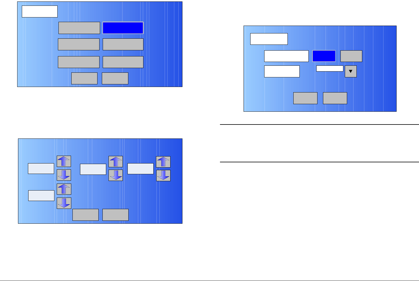
Advanced Operations 5-9MTX5000 User and Technical Manual
Figure 5-11: FMT SETUP Screen - Typical
10. Select the Audio Deviation option button and observe
the Analog Audio Deviation screen is displayed.
See Figure 5-12.
Figure 5-12: Analog Audio Deviation Screen - Typical
11. Use the up and down arrows, as required, to select the
audio deviation for Audio Ch1 thru Audio Ch4. Audio
deviation range is 0 thru 31 for each audio channel.
12. Select the Back option button and observe the FMT
SETUP screen is displayed.
FMT SETUP
Back
Video Deviation
Audio CH1
Audio CH3 Audio CH4
Audio CH2
Main
Audio Deviation
Back
Analog Audio Deviation
Audio Ch1
0
Main
Audio Ch2 Audio Ch3
Audio Ch4
00
0
13. Select the Video Deviation option button and observe
the FMT VIDEO screen is displayed. See Figure 5-13.
Figure 5-13: FMT VIDEO Screen - Typical
Note In the following step, the VIDEO DEVIATION -
4 MHz option button will be active only if the 17
MHz or 25 MHz channel plan is active in your
MTX5000 System.
14. Select the VIDEO DEVIATION - 3 MHz or 4 MHz
option button, as required, and observe the selected
option button becomes active (blue).
15. Select the VIDEO INPUT pull-down menu and select
the Composite or Baseband option, as required. See
Figure 5-14 on page 5-10.
FMT VIDEO
Back
VIDEO DEVIATION 3 MHz 4 MHz
VIDEO INPUT Composite
Main
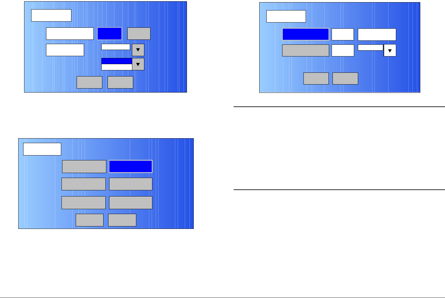
Advanced Operations 5-10MTX5000 User and Technical Manual
Figure 5-14: VIDEO INPUT Options - Typical
16. Select the Back option button and observe the FMT
SETUP screen is displayed. See Figure 5-15.
Figure 5-15: FMT SETUP Screen
17. Select the Audio CH1 option button and observe the
AUDIO CH1 screen is displayed. See Figure 5-16.
FMT VIDEO
Back
VIDEO DEVIATION 3 MHz 4 MHz
VIDEO INPUT Composite
Baseband
Composite
Main
FMT SETUP
Back
Video Deviation
Audio CH1
Audio CH3 Audio CH4
Audio CH2
Main
Audio Deviation
Figure 5-16: AUDIO CH1 Screen - Typical
Notes The ENABLE setting must be set to On to enable
the PRE-EMPHASIS option button and the audio
FREQUENCY pull-down menu.
If the ENABLE - Off option is required, go to step
18.
To enable PRE-EMPHASIS and/or select the audio
FREQUENCY, go to step 19.
18. Select the ENABLE option button to select the Off
option and observe the PRE-EMPHASIS option button
and the FREQUENCY pull-down menu become
inactive (greyed-out). Go to step 25.
19. Select the ENABLE option button to select the On
option and observe the PRE-EMPHASIS option button
becomes active (not greyed-out).
20. Select the PRE-EMPHASIS option button and select
On or Off, as required.
AUDIO CH1
Back
ENABLE Off FREQUENCY
PRE-EMPHASIS On 4830 kHz
Main
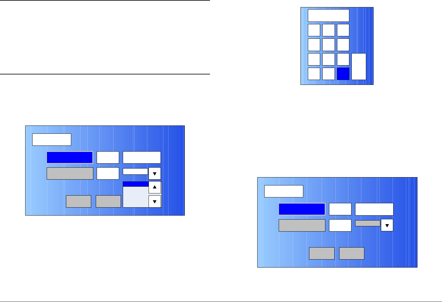
Advanced Operations 5-11MTX5000 User and Technical Manual
Note In the following step, the FREQUENCY pull-down
menu may be used to select fixed audio
frequencies or you may select the Custom option
to create custom audio frequencies.
To select a fixed audio frequency, go to step 21.
To select a custom audio frequency, go to step 22.
21. Use the FREQUENCY pull-down menu (See Figure 5-
17) to select the frequency option required and go to
step 25.
Figure 5-17: Frequency Pull-Down Menu - Typical
22. Use the FREQUENCY pull-down menu to select the
Custom option and observe the FREQUENCY option
button becomes active (not greyed-out).
23. Select the FREQUENCY option button and observe
the numeric keypad is displayed. See Figure 5-18.
AUDIO CH1
Back
ENABLE On FREQUENCY
PRE-EMPHASIS On 4830 kHz
5200 kHz
5800 kHz
6200 kHz
4830 kHz
Main
Figure 5-18: Numeric Keypad
24. Enter the custom audio frequency required (range is
4830 kHz to 8590 kHz), select the ENT key, and
observe the AUDIO CH1 screen is displayed.
25. Select the Back option button and observe the FMT
SETUP screen is displayed.
26. Select the Audio CH2 option button and observe the
AUDIO CH2 screen is displayed. See Figure 5-19.
Figure 5-19: AUDIO CH2 Screen - Typical
1 2 3
4
7
5 6
8 9
CLR 0ESC
ENT
AUDIO CH2
Back
ENABLE Off FREQUENCY
PRE-EMPHASIS On 4830 kHz
Main
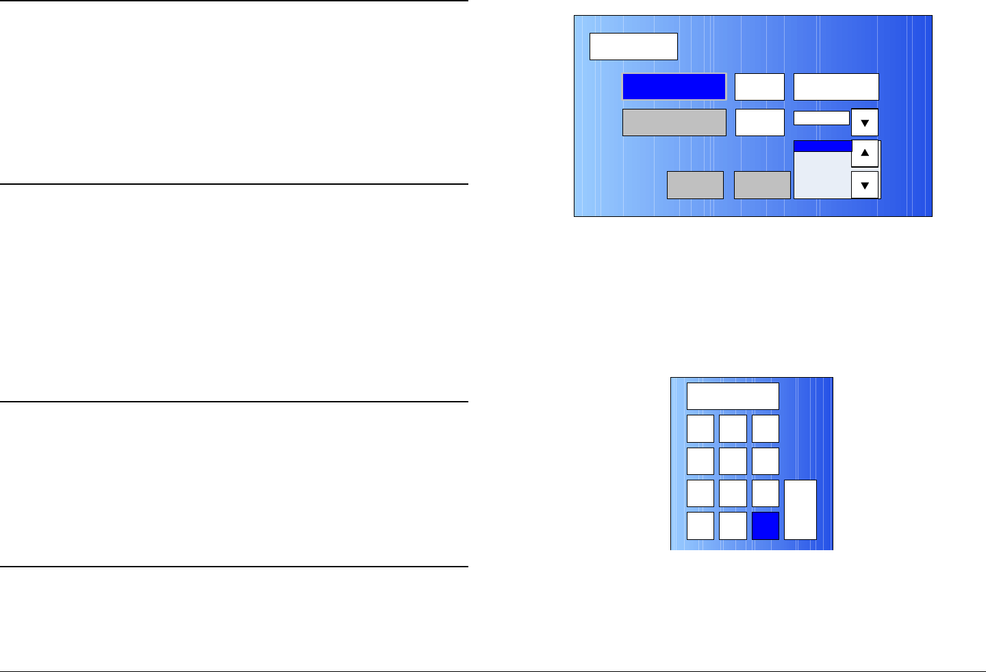
Advanced Operations 5-12MTX5000 User and Technical Manual
Notes The ENABLE setting must be set to On to enable
the PRE-EMPHASIS option button and the audio
FREQUENCY pull-down menu.
If the ENABLE - Off option is required, go to step
27.
To enable PRE-EMPHASIS and/or select the audio
FREQUENCY, go to step 28.
27. Select the ENABLE option button to select the Off
option and observe the PRE-EMPHASIS option button
and the FREQUENCY pull-down menu become
inactive (greyed-out). Go to step 34.
28. Select the ENABLE option button and observe the
PRE-EMPHASIS option button becomes active (not
greyed-out).
29. Select the PRE-EMPHASIS option button and select
On or Off, as required.
Note In the following step, the FREQUENCY pull-down
menu may be used to select fixed audio
frequencies or you may select the Custom option
to create custom audio frequencies.
To select a fixed audio frequency, go to step 30.
To select a custom audio frequency, go to step 31.
30. Use the FREQUENCY pull-down menu (See Figure 5-
20) to select the frequency option required and go to
step 34.
Figure 5-20: Frequency Pull-Down Menu - Typical
31. Use the FREQUENCY pull-down menu to select the
Custom option and observe the FREQUENCY option
button becomes active (not greyed-out).
32. Select the FREQUENCY option button and observe
the numeric keypad is displayed. See Figure 5-21.
Figure 5-21: Numeric Keypad
33. Enter the custom audio frequency required (range is
4830 kHz to 8590 kHz), select the ENT key, and
observe the AUDIO CH2 screen is displayed.
AUDIO CH2
Back
ENABLE On FREQUENCY
PRE-EMPHASIS On 4830 kHz
5200 kHz
5800 kHz
6200 kHz
4830 kHz
Main
1 2 3
4
7
5 6
8 9
CLR 0ESC
ENT
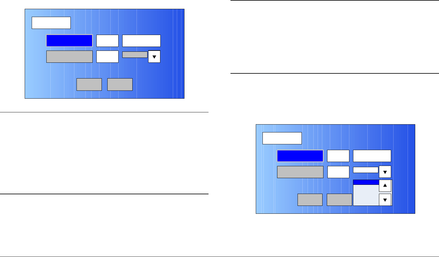
Advanced Operations 5-13MTX5000 User and Technical Manual
34. Select the Back option button and observe the FMT
SETUP screen is displayed.
35. Select the Audio CH3 option button and observe the
AUDIO CH1 screen is displayed. See Figure 5-22.
Figure 5-22: AUDIO CH3 Screen - Typical
Notes The ENABLE setting must be set to On to enable
the PRE-EMPHASIS option button and the audio
FREQUENCY pull-down menu.
If the ENABLE - Off option is required, go to step
36.
To enable PRE-EMPHASIS and/or select the audio
FREQUENCY, go to step 37.
36. Select the ENABLE option button to select the Off
option and observe the PRE-EMPHASIS option button
and the FREQUENCY pull-down menu become
inactive (greyed-out). Go to step 43.
37. Select the ENABLE option button and observe the
AUDIO CH3
Back
ENABLE Off FREQUENCY
PRE-EMPHASIS On 4830 kHz
Main
PRE-EMPHASIS option button becomes active (not
greyed-out).
38. Select the PRE-EMPHASIS option button and select
On or Off, as required.
Note In the following step, the FREQUENCY pull-down
menu may be used to select fixed audio
frequencies or you may select the Custom option
to create custom audio frequencies.
To select a fixed audio frequency, go to step 39.
To select a custom audio frequency, go to step 40.
39. Use the FREQUENCY pull-down menu (See Figure 5-
23) to select the frequency option required and go to
step 43.
Figure 5-23: Frequency Pull-Down Menu - Typical
40. Use the FREQUENCY pull-down menu to select the
Custom option and observe the FREQUENCY option
button becomes active (not greyed-out).
AUDIO CH3
Back
ENABLE On FREQUENCY
PRE-EMPHASIS On 4830 kHz
5200 kHz
5800 kHz
6200 kHz
4830 kHz
Main
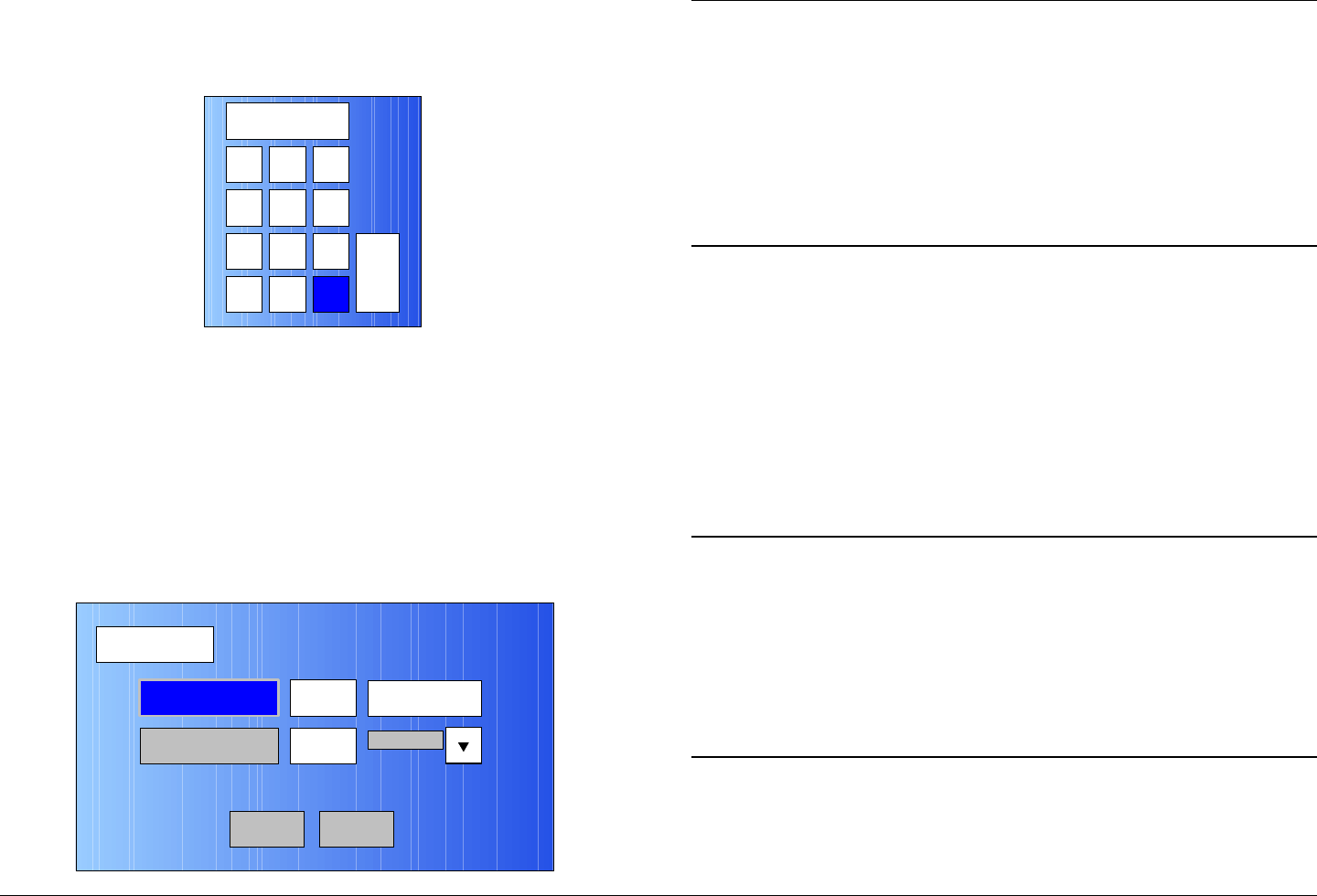
Advanced Operations 5-14MTX5000 User and Technical Manual
41. Select the FREQUENCY option button and observe
the numeric keypad is displayed. See Figure 5-24.
Figure 5-24: Numeric Keypad
42. Enter the custom audio frequency required (range is
4830 kHz to 8590 kHz), select the ENT key, and
observe the AUDIO CH3 screen is displayed.
43. Select the Back option button and observe the FMT
SETUP screen is displayed.
44. Select the Audio CH4 option button and observe the
AUDIO CH4 screen is displayed. See Figure 5-25.
Figure 5-25: AUDIO CH4 Screen - Typical
1 2 3
4
7
5 6
8 9
CLR 0ESC
ENT
AUDIO CH4
Back
ENABLE Off FREQUENCY
PRE-EMPHASIS On 4830 kHz
Main
Notes The ENABLE setting must be set to On to enable
the PRE-EMPHASIS option button and the audio
FREQUENCY pull-down menu.
If the ENABLE - Off option is required, go to step
45.
To enable PRE-EMPHASIS and/or select the audio
FREQUENCY, go to step 46.
45. Select the ENABLE option button to select the Off
option and observe the PRE-EMPHASIS option button
and the FREQUENCY pull-down menu become
inactive (greyed-out). Go to step 52.
46. Select the ENABLE option button and observe the
PRE-EMPHASIS option button becomes active (not
greyed-out).
47. Select the PRE-EMPHASIS option button and select
On or Off, as required.
Note In the following step, the FREQUENCY pull-down
menu may be used to select fixed audio
frequencies or you may select the Custom option
to create custom audio frequencies.
To select a fixed audio frequency, go to step 48.
To select a custom audio frequency, go to step 49.
48. Use the FREQUENCY pull-down menu (See Figure 5-
26 on page 5-15) to select the frequency option
required and go to step 53.
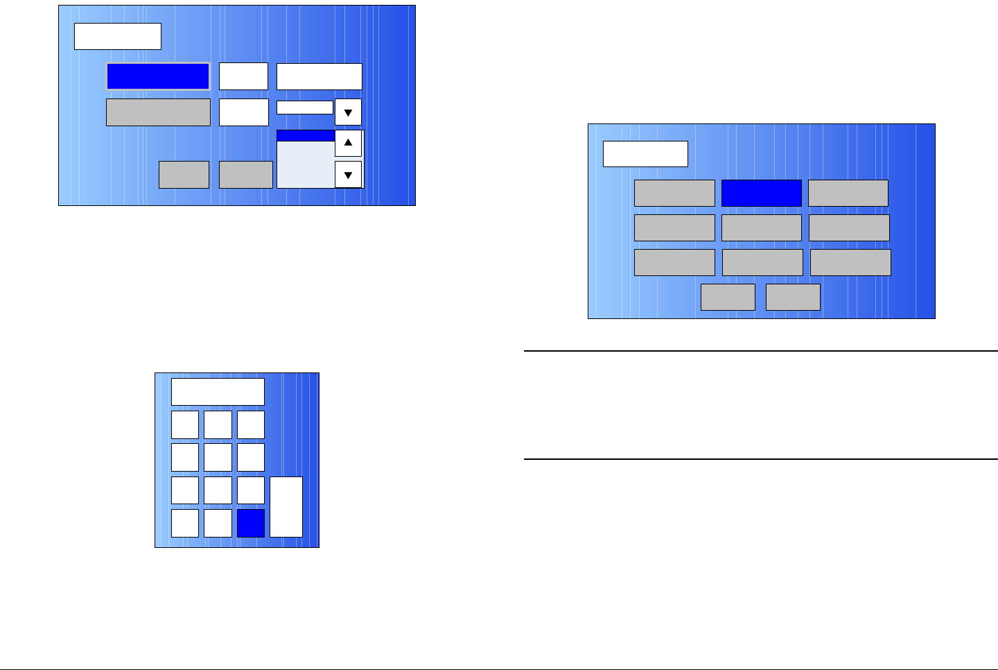
Advanced Operations 5-15MTX5000 User and Technical Manual
Figure 5-26: Frequency Pull-Down Menu - Typical
49. Use the FREQUENCY pull-down menu to select the
Custom option and observe the FREQUENCY option
button becomes active (not greyed-out).
50. Select the FREQUENCY option button and observe
the numeric keypad is displayed. See Figure 5-27.
Figure 5-27: Numeric Keypad
51. Enter the custom audio frequency required (range is
4830 kHz to 8590 kHz), select the ENT key, and
observe the AUDIO CH4 screen is displayed.
AUDIO CH4
Back
ENABLE On FREQUENCY
PRE-EMPHASIS On 4830 kHz
5200 kHz
5800 kHz
6200 kHz
4830 kHz
Main
1 2 3
4
7
5 6
8 9
CLR 0ESC
ENT
52. Select the Back option button and observe the FMT
SETUP screen is displayed.
53. Select the Back option button and observe the
Operation Mode screen is displayed. See Figure 5-
28.
Figure 5-28: Operation Mode Screen
Note When the Save As Preset screen is displayed in
the following step, the Preset Text and Save text
boxes will display the name and identification of the
analog Preset currently being used as the analog
“make-from” for this custom Preset.
54. Select the Save As Preset option button and observe
the Save As Preset screen is displayed. See
Figure 5-29 on page 5-16.
Operation Mode
Back
COFDM FMT ASI
IP
SCM
LMS-T
Save As Preset
DVBS
MPEG
Main
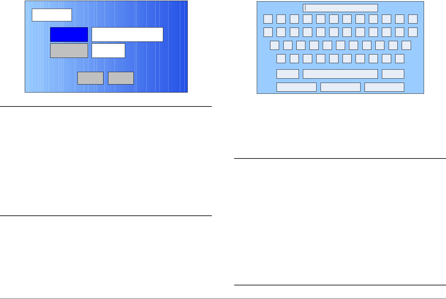
Advanced Operations 5-16MTX5000 User and Technical Manual
Figure 5-29: Save As Preset Screen - Typical
Notes In the following steps, if a factory default analog
Preset was used as a “make-from” to prepare this
custom Preset, the Preset Text text box and the
Save text box must be changed. You cannot
change or overwrite any factory default
Presets!
If a custom analog Preset was used as a “make-
from” to prepare this custom Preset, a brief
description of the custom Preset should be entered
in the Preset Text text box for easy identification
purposes.
55. Select the Preset Text option button and observe the
keyboard screen is displayed. See Figure 5-30.
Save As Preset
Back
Preset Text Analog
4.83 & 6.2, 4MHz Vid Dev
Save A
Main
Figure 5-30: Keyboard Screen
56. Enter a unique analog Preset description, as required,
and select the Enter key.
57. Observe the Save As Preset screen is displayed and
the Preset Text text box displays the Preset
description.
Notes When saving the new custom analog Preset in the
following step, the Preset number will automatically
be increased to the next available Preset number
to avoid overwriting an existing Preset.
If you wish to overwrite the existing Preset number
(unless it is a factory default Preset), enter the
Preset number to be overwritten. A warning
message will be displayed asking “Are you
sure?”. Select the Yes option button.
Once an existing custom Preset is overwritten, it
cannot be recovered. It must be re-entered from
scratch.
! @ # $ % ^ & * ( ) _ +
Q W E R T Y U I O P { }
A S D F G H J K L :
Z X C V B N M < > ?
Shift BS
Clear CancelEnter
“
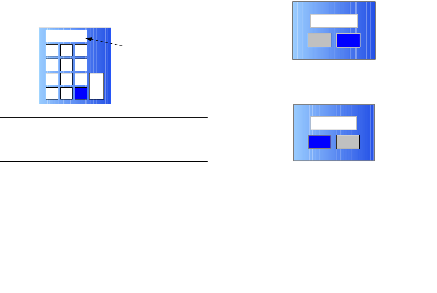
Advanced Operations 5-17MTX5000 User and Technical Manual
58. Select the Save option button and observe the
numeric keypad is displayed. See Figure 5-31.
Figure 5-31: Numeric Keypad - Typical
Notes When saving Presets in the following steps, Preset
A thru Preset J are factory default Presets. The
factory default Presets cannot be changed.
Notes To change the default Preset number, perform step
59 and go to step 60.
To accept the next available Preset number, go to
step 60.
59. Select the CLR key and enter the Preset number
required.
60. Select the ENT key and observe the Are you sure?
confirmation screen is displayed. See Figure 5-32.
1 2 3
4
7
5 6
8 9
CLR 0ESC
ENT
Next Available
Preset Number
Figure 5-32: Confirmation Screen
61. Select the YES option button and observe the Please
Wait! message box is displayed. See Figure 5-33.
Figure 5-33: Please Wait Message Box
62. After a short delay, observe the Save As Preset
screen is displayed.
63. Select the Main option button and observe the Main
screen is displayed.
5.4.2 Create or Update Digital COFDM Preset
Configuration Settings in Local Mode
The procedure required to create a new custom digital COFDM
Preset configuration or to update an existing digital COFDM
Preset configuration is contained in the following steps.
When preparing a new digital COFDM Preset, you must first
select an existing digital COFDM Preset from either one of the
No
Are you sure?
Yes
No
Please Wait!
Yes

Advanced Operations 5-18MTX5000 User and Technical Manual
digital COFDM factory default Presets or from your own custom
digital COFDM Presets. The selected Preset will be used as a
“make-from” to prepare the new digital COFDM Preset
configuration.
Please note that while factory default COFDM Presets may be
used to prepare a new Preset configuration, these factory
default Presets cannot be changed or deleted. They can only
be used as “make-froms”.
When the new configuration is prepared using the factory default
Preset, it cannot be saved with the factory Preset number or
Preset name. A new Preset number and Preset name must be
assigned to the new Preset.
When using a custom Preset as a “make-from”, the new Preset
should be saved with a new Preset number. When you save the
new Preset, the Preset number will automatically be increased to
the next available Preset number. If you select an existing
Preset number when saving the new Preset, the original custom
Preset will be overwritten and cannot be recovered. The only
way to restore a Preset that has been overwritten is to re-enter
the custom Preset data from scratch.
If you are updating configuration settings on an existing custom
Preset, when you save the configuration settings, the Preset
number will automatically be increased to the next available
Preset number. You must enter and save the configuration
settings using the original Preset number.
Note In the following steps, the color LCD display option
buttons and pull-down menu options may be
selected using either the touch screen or the
function keys and the SEL key.
1. Verify the MTX5000 IDU is powered up. See
”Powering the MTX5000 System” on page 3-7.
2. Observe the Main screen is displayed. See Figure 5-
34.
Figure 5-34: Main Screen - Typical
3. Select the L/R option button for L (local mode), as
required.
Notes If you are updating an existing digital COFDM
Preset configuration, select the Preset to be
updated in the following step.
If you are creating a new digital COFDM Preset
configuration, any digital COFDM Preset may be
selected in the following step.
4. Perform “Select Preset” on page 3-24 to select the
digital COFDM Preset required to be updated or to be
used as a “make-from”.
5. Select the Main screen PA operation button for PA
Off, as required.
Channel 1 0Offset
Antenna Ant. Pol.Antenna1 H
RFU1
No RF
RF Band
Preset A Analog
4.83 & 5.8, 3MHz Vid Dev
RF Output XX
dBm
<- Status Setup Status ->
PA Off
SUM
ODU
IDU
RF
L/R
L
L
PA
Operation
Button
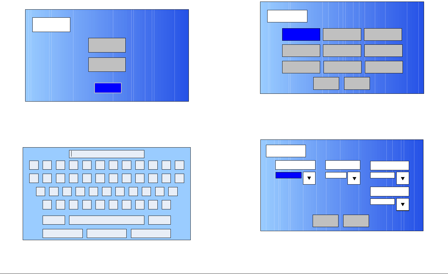
Advanced Operations 5-19MTX5000 User and Technical Manual
6. Select the Main screen Setup option button and
observe the Setup screen is displayed. See Figure 5-
35.
Figure 5-35: Setup Screen
7. Select the User option button and observe the
keyboard screen is displayed. See Figure 5-36.
Figure 5-36: Keyboard Screen
8. Enter your password, select the Enter key, and
Setup
User
Main
Radio
! @ # $ % ^ & * ( ) _ +
Q W E R T Y U I O P { }
A S D F G H J K L :
Z X C V B N M < > ?
Shift BS
Clear CancelEnter
“
observe the Operation Mode screen is displayed.
See Figure 5-37.
Figure 5-37: Operation Mode Screen
9. Select the COFDM option button and observe the
COFDM screen is displayed. See Figure 5-38.
Figure 5-38: COFDM Screen - Typical
10. Use the FEC (Forward Error Correction) pull-down
menu and select 1/2, 2/3, 3/4, 5/6, or 7/8, as required.
Operation Mode
Back
COFDM FMT ASI
IP
SCM
LMS-T
Save As Preset
DVBS
MPEG
Main
COFDM
Back
FEC Guard Interval Constellation
1/8
RF B/W
1/2 QPSK
8 MHz
Main
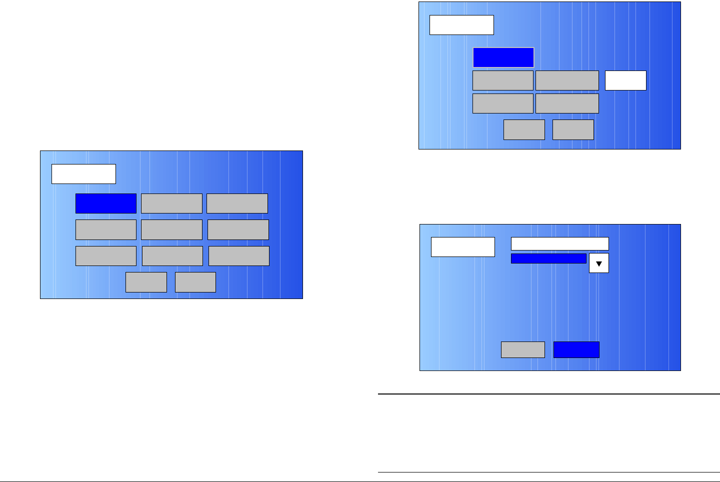
Advanced Operations 5-20MTX5000 User and Technical Manual
11. Use the Guard Interval pull-down menu and select
1/32, 1/16, 1/8, or 1/4, as required.
12. Use the Constellation pull-down menu to select
QPSK, 16-QAM, or 64-QAM, as required.
13. Use the RF B/W pull-down menu to select 6 MHZ,
7 MHZ, or 8 MHZ, as required.
14. Select the Back option button and observe the
Operation Mode screen is displayed. See Figure 5-
39.
Figure 5-39: Operation Mode Screen
15. Select the MPEG option button and observe the
MPEG screen is displayed. See Figure 5-40.
Operation Mode
Back
COFDM FMT ASI
IP
SCM
LMS-T
Save As Preset
DVBS
MPEG
Main
Figure 5-40: MPEG Screen - Typical
16. Select the Video In option button and observe the
Video In screen is displayed. See Figure 5-41.
Figure 5-41: Video In Screen - Typical
Note In the following step, select an Input option
applicable to the licensed options contained in your
MTX5000 IDU only. Selection of an option that is
not licensed in your radio will cause the IDU to
operate in the NTSC default mode.
MPEG
Back
Video In
Audio In
Encoder
NormalSpectrum Invert
Encoding
Main
Video In
Back
Input
NTSC
Video In2
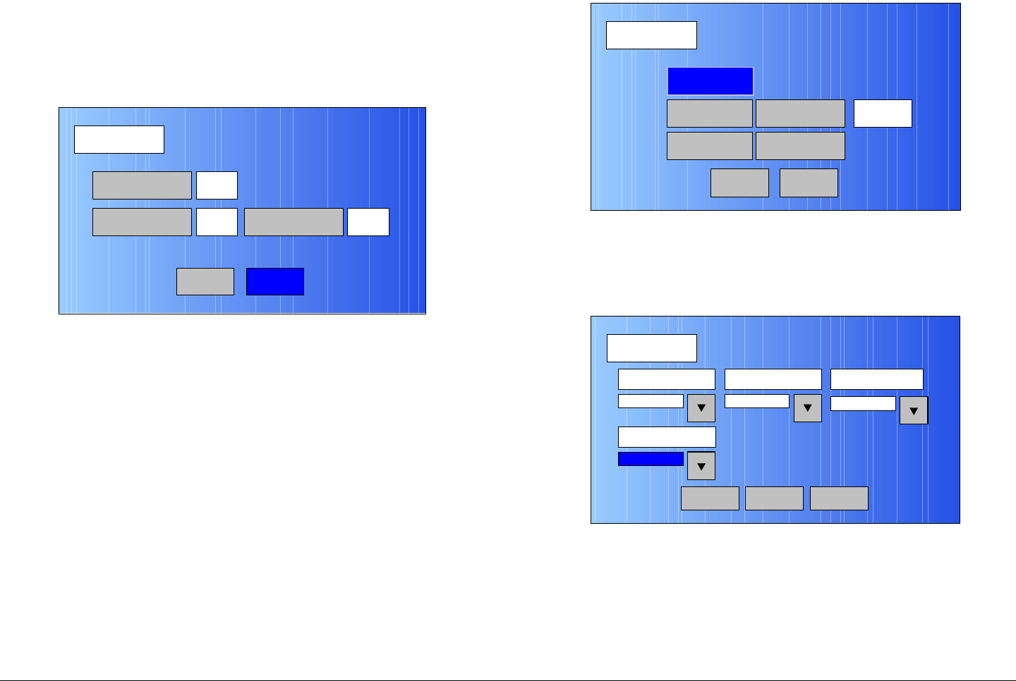
Advanced Operations 5-21MTX5000 User and Technical Manual
17. Use the Input pull-down menu to select the video
input option required.
18. Select the Video In2 option button and observe the
Video In screen 2 is displayed. See Figure 5-42.
Figure 5-42: Video In Screen 2 - Typical
19. Select the Noise Reduction option button for On or
Off, as required.
20. Select the SDI Auto Line option button for On or Off,
as required.
21. Select the HD Test Pattern option button for On or
Off, as required.
22. Select the Back option button and observe the Video
In screen is displayed.
23. Select the Back option button and observe the MPEG
screen is displayed. See Figure 5-43.
Video In
Back
Noise Reduction
SDI Auto Line
Off
Off HD Test Pattern Off
Main
Figure 5-43: MPEG Screen - Typical
24. Select the Audio In option button and observe the
AUDIO 1 screen is displayed. See Figure 5-44.
Figure 5-44: AUDIO 1 Screen - Typical
25. Use the Mode pull-down menu to select Stereo or
Dual Mono, as required.
26. Use the Standard pull-down menu to select Off,
MPEG Layer II, Linear PCM, or MPEG Layer I, as
required.
MPEG
Back
Video In
Audio In
Encoder
NormalSpectrum Invert
Encoding
Main
AUDIO 1
Back
Mode Standard Bit Rate
MPEG Layer II
Input
Dual Mono 192 Kbps
Analog
Audio 2Main
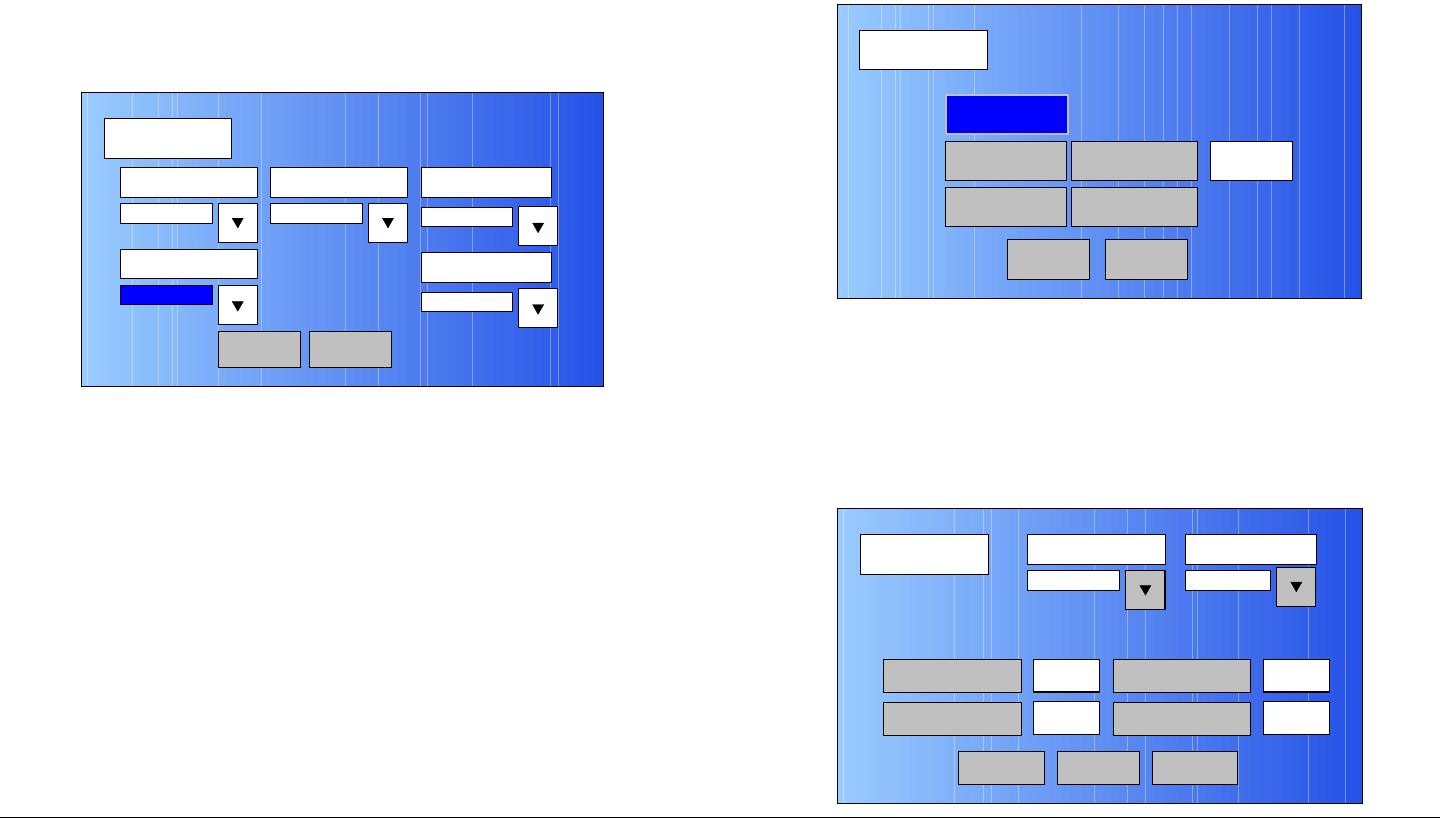
Advanced Operations 5-22MTX5000 User and Technical Manual
27. Use the Bit Rate pull-down menu to select 128 Kbps,
160 Kbps, 192 Kbps, 224 Kbps, 256 Kbps, 320
Kbps, or 384 Kbps, as required.
28. Use the Input pull-down menu to select Test Tone,
Analog, or SDI Emb, as required.
29. Select the Audio 2 option button and observe the
AUDIO 2 screen is displayed. See Figure 5-45.
Figure 5-45: AUDIO 2 Screen - Typical
30. Use the Mode pull-down menu to select Stereo or
Dual Mono, as required.
31. Use the Standard pull-down menu to select Off,
MPEG Layer II, Linear PCM, or MPEG Layer I, as
required.
32. Use the Bit Rate pull-down menu to select 128 Kbps,
160 Kbps, 192 Kbps, 224 Kbps, 256 Kbps, 320
Kbps, or 384 Kbps, as required.
33. Use the Input pull-down menu to select Test Tone,
Analog, SDI Emb, AES-EBU, or Channel Ide, as
required.
34. Use the Balance pull-down menu to select
Unbalanced or Balanced, as required.
AUDIO 2
Back
Mode Standard Bit Rate
MPEG Layer II
Input
Dual Mono 192 Kbps
Analog
Main
Balance
Unbalanced
35. Select the Back option button and observe the AUDIO
1 screen is displayed.
36. Select the Back option button and observe the MPEG
screen is displayed. See Figure 5-46.
Figure 5-46: MPEG Screen - Typical
37. Select the Spectrum Invert option button to select
Normal or Inverted, as required.
38. Select the Encoder option button and observe the
Encoder screen is displayed. See Figure 5-47.
Figure 5-47: Encoder Screen - Typical
MPEG
Back
Video In
Audio In
Encoder
NormalSpectrum Invert
Encoding
Main
Encoder
Back
Mode Bit Rate
Low delay
4.9 Mb/s
Bit Rate
On
MP@ML
Encoder 2
Bit Rate Auto GOP Length 15
Main
ASI Bit Rate 5.529
Mb/s
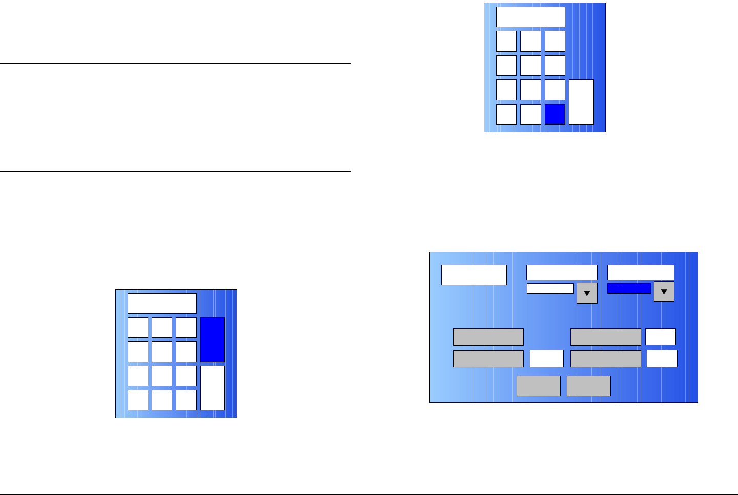
Advanced Operations 5-23MTX5000 User and Technical Manual
39. Select the Mode pull-down menu and select Standard
or Low delay, as required.
40. Select the Bit Rate pull-down menu and select
MP@ML or 422P@ML, as required.
Notes In the following step, if the Bit Rate Auto option
button option selected is On, the Bit Rate option
button will be inactive (greyed out). Go to step 44.
If the Bit Rate Auto option button option selected
is Off, the Bit Rate option button will be active. Go
to step 42.
41. Select the Bit Rate Auto option button for Off or On,
as required.
42. Observe the Bit Rate option button is active. Select
the Bit Rate option button and observe the numeric
keypad is displayed. See Figure 5-48.
Figure 5-48: Numeric Keypad
43. Enter the bit rate required, select the ENT key, and
observe the Encoder screen is displayed.
44. Select the GOP Length option button and observe the
numeric keypad is displayed. See Figure 5-49.
1 2 3
ESC
0
4
7
5 6
8 9
DEL 0ESC
ENT
Figure 5-49: Numeric Keypad
45. Enter the Group of Pictures (GOP) number required,
select the ENT key, and observe the Encoder screen
is displayed.
46. Select the Encoder 2 option button and observe the
Encoder screen 2 is displayed. See Figure 5-50.
Figure 5-50: Encoder Screen 2 - Typical
47. Select the Horiz Resolution pull-down menu and
select 720, 704, 544, 528, 480, or 352, as required.
48. Select the Aspect Ratio pull-down menu and select
4:3 or 16:9, as required.
123
4
7
5 6
8 9
CLR 0ESC
ENT
Encoder
Back
Horiz Resolution Aspect Ratio
720
PID
Off
4:3
PTS per Picture VBI Off
Main
Remux Off
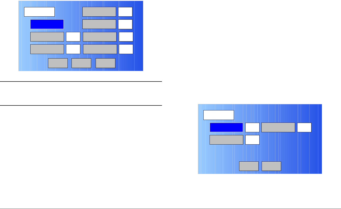
Advanced Operations 5-24MTX5000 User and Technical Manual
49. Select the PID option button and observe the PID
screen is displayed. See Figure 5-51.
Figure 5-51: PID Screen - Typical
Notes To select the default PID settings, go to step 50.
To enter individual PID settings, go to step 51.
50. Select the DEFAULT option button and observe the
default PID settings are displayed. Go to step 71.
51. Select the DATA option button and observe the
numeric keypad is displayed.
52. Enter the DATA PID required, select the ENT key, and
observe the PID screen is displayed.
53. Select the AUDIO A option button and observe the
numeric keypad is displayed.
54. Enter the AUDIO A PID required, select the ENT key,
and observe the PID screen is displayed.
55. Select the PMT option button and observe the numeric
keypad is displayed.
PID
Main
DEFAULT
PMT
300
12 AUDIO B 201
DATA
AUDIO A
100
200
VIDEO PCR 8190
Back Next
56. Enter the PMT PID required, select the ENT key, and
observe the PID screen is displayed.
57. Select the AUDIO B option button and observe the
numeric keypad is displayed.
58. Enter the AUDIO B PID required, select the ENT key,
and observe the PID screen is displayed.
59. Select the VIDEO option button and observe the
numeric keypad is displayed.
60. Enter the Video PID required, select the ENT key, and
observe the PID screen is displayed.
61. Select the PCR option button and observe the numeric
keypad is displayed.
62. Enter the PCR PID required, select the ENT key, and
observe the PID screen is displayed.
63. Select the Next option button and observe the PID-2
screen is displayed. See Figure 5-52.
Figure 5-52: PID-2 Screen - Typical
64. Select the Program ID option button and observe the
numeric keypad is displayed. See Figure 5-53 on
page 5-25.
PID-2
Main
Program ID
Transport ID 1
Network ID3 1
Back
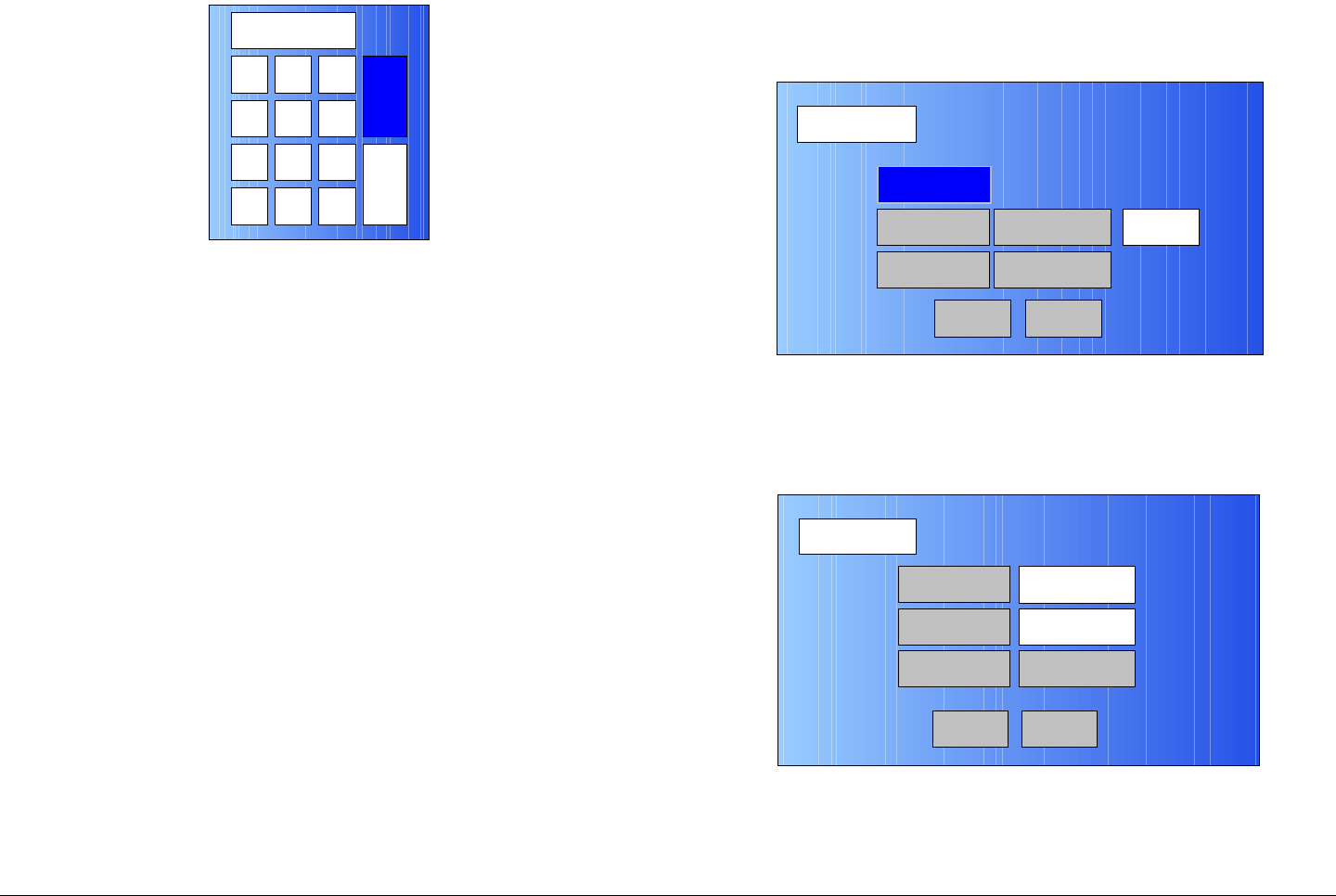
Advanced Operations 5-25MTX5000 User and Technical Manual
Figure 5-53: Numeric Keypad
65. Enter the Program ID PID required, select the ENT
key, and observe the PID-2 screen is displayed.
66. Select the Network ID option button and observe the
numeric keypad is displayed.
67. Enter the Network ID PID required, select the ENT
key, and observe the PID-2 screen is displayed.
68. Select the Transport ID option button and observe the
numeric keypad is displayed.
69. Enter the Transport ID PID required, select the ENT
key, and observe the PID-2 screen is displayed.
70. Select the Back option button and observe the PID
screen is displayed.
71. Select the Back option button and observe the
Encoder screen is displayed.
72. Select the Remux option button for On or Off, as
required.
73. Select the PTS per Picture option button for On or
Off, as required.
74. Select the VBI option button for On or Off, as required.
75. Select the Back option button and observe the
Encoder screen is displayed.
1 2 3
ESC
0
4
7
5 6
8 9
DEL 0ESC
ENT
76. Select the Back option button and observe the MPEG
screen is displayed. See Figure 5-54.
Figure 5-54: MPEG Screen - Typical
77. Select the Encoding option button and observe the
Encoding screen is displayed. See Figure 5-55.
Figure 5-55: Encoding Screen - Typical
78. Select the Service Name option button and observe
the keyboard screen is displayed. See Figure 5-56 on
page 5-26.
MPEG
Back
Video In
Audio In
Encoder
NormalSpectrum Invert
Encoding
Main
Encoding
Back
Service Name
Network Name
EBS/BISS Wayside data
Service 01
Main
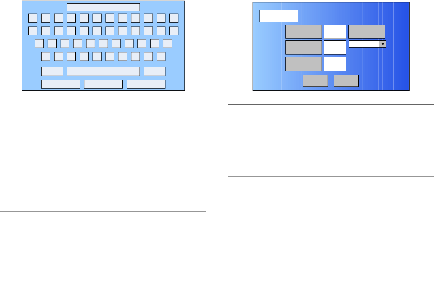
Advanced Operations 5-26MTX5000 User and Technical Manual
Figure 5-56: Keyboard Screen
79. Enter the service name required, select the Enter key,
and observe the Encoding screen is displayed.
80. Select the Network Name option button and observe
the keyboard screen is displayed.
81. Enter the network name required, select the Enter
key, and observe the Encoding screen is displayed.
Notes If your MTX5000 IDU contains a licensed EBS or
BISS encryption option, go to step 82.
If your MTX5000 IDU does not contain a licensed
EBS or BISS encryption option, go to step 88.
82. Observe the EBS/BISS option button is active (not
greyed-out).
83. Select the EBS/BISS option button and observe the
Encryption screen is displayed. See Figure 5-57.
! @ # $ % ^ & * ( ) _ +
Q W E R T Y U I O P { }
A S D F G H J K L :
Z X C V B N M < > ?
Shift BS
Clear CancelEnter
“
Figure 5-57: Encryption Screen
Notes You can only have one licensed encryption option
contained in your MTX5000 IDU.
When the Scrambling pull-down menu EBS,
BISS-1, or BISS-E option is selected in the
following step, the selected option key will be
active, but the two remaining option buttons will
become inactive (greyed-out).
84. Select the Scrambling pull-down menu EBS, BISS-1,
or BISS-E option, as required, and observe the
selected EBS, BISS-1, or BISS-E Key option button is
active.
85. Select the EBS, BISS-1, or BISS-E Key option button,
as required, and observe the alphanumeric keypad is
displayed. See Figure 5-58 on page 5-27.
Encryption
Back
EBS Key
BISS-1 Key
BISS-E Key
xx Scrambling
xx
xx
Main