Microwave Radio Communications STAHPU2D STRATA Amplifier User Manual Strata Radio Report Ch
Microwave Radio Communications LLC STRATA Amplifier Strata Radio Report Ch
Manual

Strata Operations Guide
- 1 -
Strata Transmitter
Operations Guide
Revision 3.0
May 2003
Microwave Radio Communications 101 Billerica Avenue, Bldg 6
(978) 671-5700 N. Billerica, MA 01862-1256
www.mrcbroadcast.com
Strata Operations Guide
- 2 -
Introduction
The Microwave Radio Communications (MRC) Strata system provides a reliable and highly flexible
video microwave transport system. This operations guide provides basic system operations information
and details for hands-on operation of this equipment.
System Description
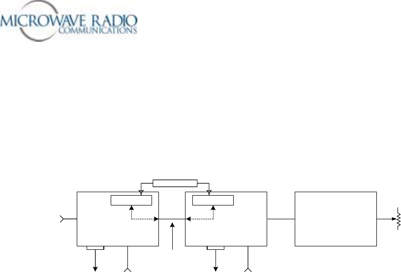
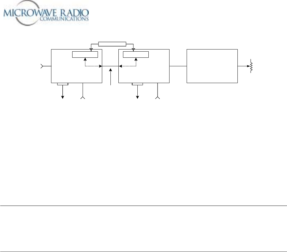
Figure 1 below shows the overall Strata system architecture for a fully equipped system.
TCU TXU HPU
!
NTSC
!
PAL
!
SDI
!
ASI
!
IF
RF OUT
RF/DC
Telemetry Telemetry
IF or Baseband Signal
DC Simplex Powering
IN
Dummy Load
12 v to 48 v
DC
RS-232
1.84 MHz OOK Tone
12 v to 48 v
DC
RS-232
Figure 1 – Strata Transmitter System Architecture
The primary system features are:
oLightweight, Modular, Multi-Unit Design
oAnalog, Digital, or Analog/Digital Switchable
oMPEG Encoding (4:2:0, 4:2:2)
oCOFDM Modulation with Selectable Guard Interval
oDigital Modulation for QPSK, 16QAM, and 64QAM
oNTSC or PAL Modulation with Audio (4 mono or 2 stereo)
oTripod, Half Rack, or Full Rack Mounts
oFront Panel Remote Controlled
oBands from 2 to 15 GHz
oWide Choice of Antennas
Note that the TCU (Transmitter Control Unit) and the TXU (Transmitter Unit) may be operated in a
stand-alone configuration depending on specific video transport applications.
TCU Description
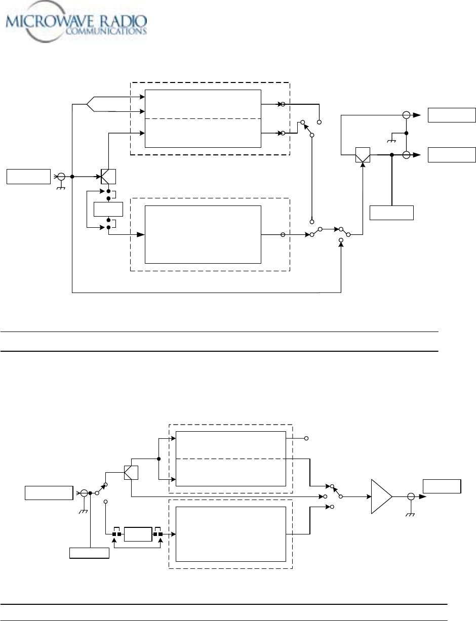
The TCU component can accept a wide variety of signal formats and provide several different output
signal formats. Figure 2 below shows the basic functions of the TCU.
Strata Operations Guide
- 3 -
MPEG
COFDM
FMT
COAX IN
COFDM
70 MHZ
MONITOR
COAX OUT
SDI
ASI
FMT CV
Filter
!
NTSC
!
PAL
!
SDI
!
ASI
!
IF
MPEG CV
Telemetry
ASI
70 MHz IF Bypass
Note: Either or both MPEG/COFDM or
FMT boards may be installed
!
COFDM
!
IF CV
!
IF
!
ASI
IF CV
ASI Only Mode
Figure 2 - Strata TCU Functional Diagram
Note: The TCU may be supplied with or without the MPEG/COFDM or FMT options.
TXU Description
Like the TCU component, the TXU can accept a wide variety of signal formats but includes an RF up-
converter for use in transporting signals over a microwave radio link. Figure 3 below shows the basic
functions of the TXU.
MPEG
COFDM
FMT
SIGNAL IN
ASI MON
ASI COFDM
70 MHZ
70 MHZ
RF OUT
SDI MPEG
MPEG CV
ASI Input
FMT CV
!
NTSC
!
PAL
!
SDI
!
ASI
!
IF
Filter
Telemetry
SDI/ASI
IF
CV
IF/RF Up Converter/Amplifier
70 MHz
Figure 3 – Strata TXU Functional Diagram
Note: The TXU may be supplied with or without the MPEG/COFDM or FMT options.
Strata Operations Guide
- 4 -
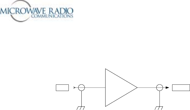
HPU Description
For those applications requiring a higher RF output level, the HPU (High Power Unit) may be used to
boost the signal level to between 2 and 12 watts of microwave output power depending on the modulation
format used. Figure 4 below shows the functional architecture of the HPU device.
HPURF IN RF OUT
Figure 4 – HPU Functional Diagram
Theory of Operation
The Strata TX system is comprised of the following primary components:
• Command and Control Power Supply module
• Combiner Circuit
• MPEG encoder/COFDM modulator module (digital mode)
• FMT (FM Transmitter) (analog mode)
• IF/RF Unit
• HPU (High Power Unit)
Note that some or all of these components may be included in a fully functional Strata TX system
depending on specific customer applications, e.g., switchable analog and digital transmitting system, etc.
Where switchable analog and digital video transmission is required, the Strata TX system installs the
digital and analog video modulator modules and the IF/RF module in separate housings. In this case a
TCU (Transmitter Control Unit) houses the MPEG/COFDM, FMT and Combiner circuits with the IF/RF
unit installed in a separate TXU (Transmitter Unit) housing. This arrangement also allows the video
modulation components (TCU) to be physically separated from the IF/RF up-converter by up to 600 feet.
Command and Control Power Supply
The TCU and TXU Command and Control/Power Supply modules contain external and internal
communications circuitry as well as supplying the necessary system voltages. The power supply portion
accepts a wide range DC input voltage (+10.5 to +48 volts) and distributes appropriate output voltages to
the various circuits. The command and control circuits handle inter-module communications and provide
external RS-232 communications to external peripheral equipment, such as a remote control device
(helicopter operation) or to a PC capable of running Windows based configuration software. An on-board
microprocessor manages the system configuration and operation of all modules to which it is connected,
i.e., MPEG/COFDM, FMT, IF/RF modules, etc. In addition, for those applications that employ both
TCU and TXU housings, a communications link superimposed over the inter-connecting IF coaxial cable
provides communications to all system modules. This ensures the TCU and TXU may control each
other’s operation, i.e., permit switching modes of operation, change system presets, etc.

Strata Operations Guide
- 5 -
Therefore, where both a TCU and TXU are used, total system control may be accomplished using front
panel or remote control from either housing.
MPEG/COFDM Encoder/Modulator
This is the heart of the Strata TX digital mode circuitry. This versatile circuit may be configured to
accept a wide range of digital or analog video and audio signal inputs and provide COFDM (70 MHz), IF
(70 MHz) or ASI video signal outputs. When installed in a TCU housing, the various signal inputs and
outputs are connected through the TCU Combiner circuit where the various signal inputs and outputs are
switched using software controls.
FMT
The optional FMT module accepts standard NTSC or PAL analog video and audio signals and FM
modulates these signals on a 70 MHz carrier. Using the MRC supplied configuration software, four
different audio sub-carrier frequencies may be defined in which up to four standard audio signals may be
transported with the associated video signal. Note that audio deviation levels are software controlled and
must be provisioned at the MRC factory when ordering this option.
TCU
The TCU may house either or both digital and analog video modulation modules. Where a customer
application might initially employ only analog video transmission but anticipates migrating to dual
(switchable) analog and digital operation, the TCU may be upgraded to add the MPEG/COFDM module
to provide this additional capability. Where only digital or analog video transmission is desired, the
MPEG/COFDM or FMT modules may be installed in a TXU housing thereby eliminating the need for a
TCU. Note that the Strata TX design does not permit splitting digital and analog video modulator
modules between a TCU and TXU. A TCU configuration may also include a “stand-alone” option where
either or both MPEG/COFDM and FMT modules may be used independent of the TXU. This
arrangement permits using a TCU equipped with analog and/or digital video modulation modules for a
variety of signal input and signal output configurations, including a digital option using NTSC or PAL
composite video input and ASI (digital) signal output.
TXU
The TXU always houses the IF/RF module, which accepts either a 70 MHz COFDM, FMT IF, or external
70 MHz input signal and up-converts these signals to the appropriate RF band. The RF frequency
synthesizer circuit included in the IF/RF unit, along with the command and control module, provide the
means to channelize RF video and audio signals in the 2 GHz RF band. Standard U.S. FCC band plans,
as well as customer created channel plans, may be accommodated using the Strata TX Windows based
configuration software. As noted above, the TXU may also include either an MPEG/COFDM or FMT
module (but not both) in which case the TXU serves as a stand-alone digital or analog video microwave
transmission system.
HPU
The optional HPU (High Power Unit) is designed to work with a companion TXU in which case RF
output signals from the TXU are connected to the RF input jack of the HPU. In the case of analog
microwave transmission, the RF output of the TXU is amplified operating the HPU RF amplifier in the
non-linear region (saturated) providing RF output levels at the 12 watt level (+41 dBm). In the case
where COFDM RF signals are used, software controlled back-off attenuation is applied to operate the
HPU RF amplifier in the linear region.
Strata Operations Guide
- 6 -
These back-off levels are carefully measured and configured as part of MRC factory adjustment
procedures and ensure digital mode RF output signals provide optimum performance. Therefore,
depending on what digital mode modulation format is selected, i.e., QPSK, 16 QAM or 64 QAM, or if an
HPU is used, previously configured transmitter back-off levels are applied to ensure the Strata TX RF
output signals operate with minimum Inter-Modulation Distortion (IMD). These carefully measured and
configured transmitter back-off levels are stored in the TXU IF/RF unit and are applied depending on
which particular operating mode is selected. Typical digital mode RF levels vary from 5 watts to 2 watts
output depending mostly on the modulation format selected.
Overall Operational Details
The following details apply when operating the Strata system using either the TCU or TXU front panel
controls:
1. When companion TXU or TCU devices are inter-connected via coaxial cables, an inter-unit telemetry
link is established. This feature allows overall system operation and configuring to be accomplished
from either the TCU or TXU devices if both are used. For example, the microwave transmitter may
be keyed ON or OFF from either device.
2. A configuration software tool (Strata TX Configurator) may be used to review and modify certain
system configuration options as described in this document.
Special Note: All radio systems leaving the MRC factory are adjusted per standard industry (default)
settings, i.e., video and audio levels versus FM deviation (analog), as well as digital and analog IF and RF
levels, etc. In addition, transmitter back-off (IMD) and analog audio levels are carefully adjusted using
special software tools. Many of these settings are software controlled and cannot be adjusted in the field.
How to View Configuration Parameters and Control the TCU/TXU Units from the Front Panel
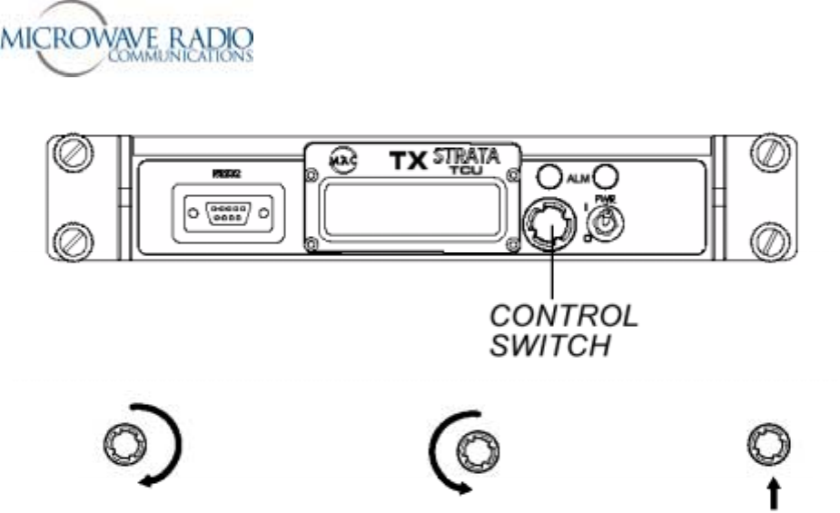
Figure 5 below shows the basic TCU/TXU control functionality using the front panel control switch:
Strata Operations Guide
- 7 -
Display Monitor Screen Push to Select
Rotate to Change Push to Select
Figure 5 – Front Panel Switch Control
TCU/TXU Front Panel Control Settings
The front panel control switch is used to select a limited number of front panel control functions. Rotating
the switch counterclockwise allows access to mode selection choices, while rotating the switch clockwise
allows access to monitoring the current mode of operation. The plunger action of the switch is used to
select the appropriate mode of operation. The TXU and associated HPU (High Power Unit), if equipped,
is keyed ON or OFF by compressing and holding the front panel control switch for one second from any
menu page. The Strata TX system is transmitting when the front panel blue “XMIT” LED is illuminated.
When the menu display is inactive for more than 7 seconds, the display will revert back to the main menu.
The following front panel control selections are available:
• Set RF Channel
• Change Preset – Presets #1 to #9
• Set Power Out – HPU attenuation control
• HPU Present
• 75 Ohm Coax DC Power ON/OFF – Coaxial cable DC power ON/OFF control
Note: The remainder of front panel selections allow monitoring previously configured parameters and
system status, including alarm indications, power output, etc.
Details related to the use of Strata TX front panel controls are found on the following page.

Strata Operations Guide
- 8 -
RF Channel Select
The radio is pre-programmed with a number of RF channel frequencies associated with up to 9 preset
configurations. Use this feature to monitor the currently configured RF frequencies. Note: If these
frequencies are known as part of a customer order, they may be factory set to customer requirements or
added or modified per customer request.
Select Preset Setting
Used to select a pre-configured configuration. Up to 9 different configurations may be stored and
configured in conjunction with the Strata TX Configurator utility.
Set Attenuation Value (Transmitter Back Off Level)
Used to set the transmitter output power (and linear operating point) of the radio system. Adjustable from
0 to 31 dB in 1 dB increments. Push to select.
Note: Maximum power output occurs with 0 dB of attenuation applied.
75 Ohm Coax ON/OFF
Used to activate or de-activate DC powering a TCU or TXU through the inter-connecting IF coaxial
cable.
Front Panel Transmitter Power Monitoring
The current TX output power reading available on the front panel may be used as a general reference and
is accurate to within +/- 1 dB.
HPU Present
Identifies and configures use of the HPU option connected to the TXU device.
Please see the front panel menu guide on the following page for details related to front panel operation.
Strata Operations Guide
- 9 -
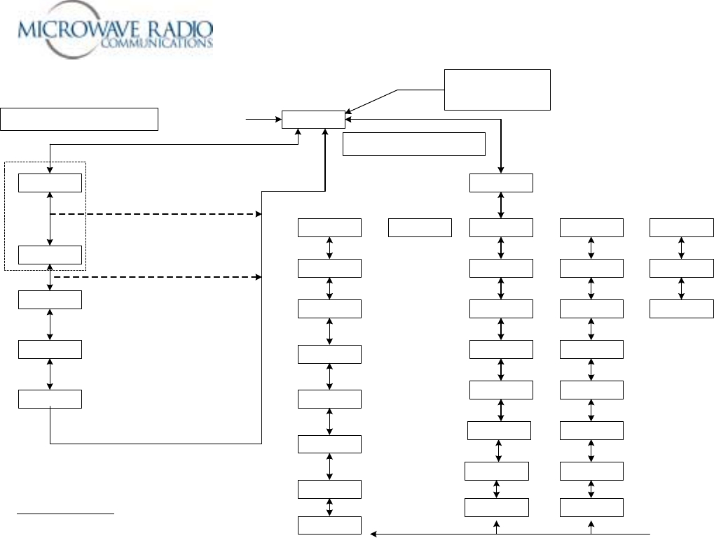
Preset #1
HPU In C9
@ DC Power Up
Change Preset
Preset #1
Set Channel
Ch 9
HPU Coax
HPU Present
75 Ohm Coax
Power On
2475.500 MHz
HPU Off C9
Mode
COFDM - IF
Video Delay
Normal
MPEG Audio A
Analog Stereo
Color Bar Off
Pilot Off
Control Menu Access
Scroll Menu Button to Left - Push to Select
Turn Transmitter ON from
any menu screen -
Push
menu button in for 1 second
Blue TX light ON
Control Menu Access:
Scroll Menu Button to Right to Monitor
Caution:
Enables HPU operation and DC
voltage on coax (from the TXU) when
transmitting - push to activate or deactivate
HPU.
Caution:
This function enables DC voltage to
flow between the TCU and TXU on the IF
coax cable - push to turn On and Off.
RF Configuration status
(Pout level - TXU only)
COFDM Config Status
with bit rate flashing
MPEG Audio A
Config Status
Video Input Status &
MPEG Chroma
Color Bar & Pilot
Status Indicator
Caution:
DC ouput voltage from TXU is slaved
to the blue light condition shown as the "HPU
In" condition when transmitting.
1) Push to activate
2) Rotate to change
3) Push to select
QPSK 8MHz
FEC 1/2 GI 1/8
NTSC
Video In 4:2:0
Video Input error -
flashes w/no video
Mode
Analog - IF Mode
COFDM ASI In
Mode
Ext IF Input
Audio #1 On
Pre 4.83MHz
Audio #2 On
Flat 6.20MHz
Audio #3 Off
Pre 6.80MHz
Audio #4 Off
Pre 7.20MHz
Vid Dev 4MHz
Pre 525L In
QPSK 8MHz
FEC 1/2 GI 1/8
Color Bar Off
Pilot Off
MPEG Audio B
Config Status
Mode
MPEG Output
NTSC
Vid In 4:2:0
Video Delay
Normal
MPEG Audio A
Analog Stereo
MPEG Audio B
Analog Stereo
Color Bar Off
Monitor Menus
A Function of IF Mode Selection
Note:
For helicopter applications the channel select will be included with the
preset conditions.
*
Presetable Parameters
Video Input Chroma
Delay Mode FEC
ASI Output COFDM Bandwidth
BISS - On/Off Guard Interval
BISS Key Modulation
Audio Input Conditions A & B VBI - On/Off
Audio Mode Conditions
Color Bars/Pilot Condition - Service Name/Network Name
IF Mode of Operation
Analog Audio Subcarrier On/Off
A
nalo
g
Audio Subcarrier Fre
q
uenc
y
MPEG Audio B
Analog Stereo
Video delay
ASI Bit Rate
10.2000 Mbs
Set Power Out
Atten 0 dB
Note:
Last operational state will be saved on power down.
1) Push to activate
2) Rotate to change
3) Push to select - up to 9 presets
1) Push to activate
2) Rotate to change
3) Push to select - 0 -31 dB values
back to main
menu after set
back to main
menu after set
( Default to Main Menu after 7 seconds of inactivity)
Pilot Off
Strata Front Panel Operation
*
Error Page
Error Page Error Page
Refer to MID errors
Strata Front Panel Guide Diagram
Strata Operations Guide
- 10 -
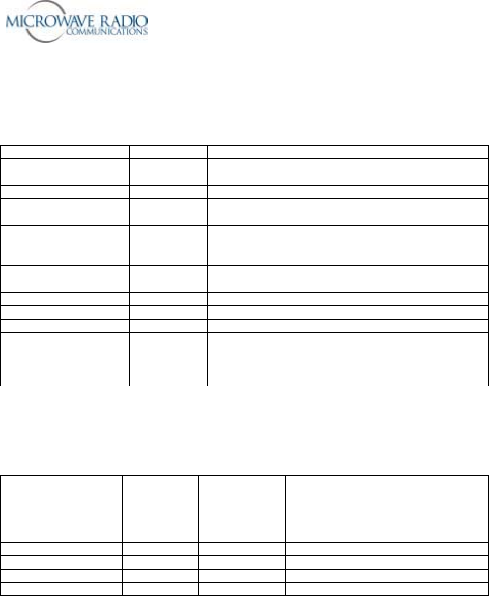
Supported Strata TX System Configuration Options
The following information may be used to identify which Strata TX system options may be used for
specific customer applications.
TCU Supported Signal Options
Hardware Option Signal Input Signal Output Monitor Out Notes
* MPEG/COFDM Only NTSC/PAL ASI Various formats
* MPEG/COFDM Only SDI (525/625) ASI Various formats
* MPEG/COFDM Only NTSC/PAL COFDM - IF COFDM Various formats
* MPEG/COFDM Only SDI (525/625) COFDM - IF COFDM Various formats
* MPEG/COFDM Only ASI COFDM - IF COFDM Various formats
* MPEG/COFDM Only IF IF IF IF Bypass Mode
FMT Only NTSC/PAL IF CV IF CV NTSC/PAL CV IF
FMT Only IF IF IF IF Bypass Mode
* MPEG/COFDM + FMT NTSC/PAL ASI Various formats
* MPEG/COFDM + FMT SDI (525/625) ASI Various formats
* MPEG/COFDM + FMT NTSC/PAL COFDM - IF COFDM Various formats
* MPEG/COFDM + FMT NTSC/PAL IF CV IF CV NTSC/PAL IF
* MPEG/COFDM + FMT SDI (525/625) COFDM - IF COFDM Various formats
* MPEG/COFDM + FMT ASI COFDM - IF ASI or COFDM Various formats
* MPEG/COFDM + FMT IF IF IF IF Bypass Mode
Notes:
* = ASI output possible when TCU used in stand-alone (MPEG only) mode
TXU Supported Signal Options
Hardware Option Signal Input Signal Output Notes
MPEG/COFDM Option NTSC/PAL COFDM - RF Various formats
MPEG/COFDM Option SDI (525/625) COFDM - RF Various formats
MPEG/COFDM Option ASI COFDM - RF Various formats
MPEG/COFDM Option IF RF Up-converted Channelized RF signal
FMT Option NTSC/PAL CV - RF NTSC/PAL CV Channelized RF
FMT Option IF RF Up-converted Channelized RF signal
No options installed IF RF Up-converted Channelized RF signal
Note: TXU supports either MPEG/COFDM option or FMT option, but not both.

Strata Operations Guide
- 11 -
Configuring the Radio System using the TCU/TXU Serial Port and the
“Strata TX Configurator” Software Utility
Basic Strata TX Configuration Details
The following basic system configuration settings may be administered using the Strata TX Configurator
software utility.
• COFDM IF Mode – 70 MHz COFDM IF output from the internal COFDM/MPEG board supplied to
output and monitor ports (to TXU if present).
• IF Input – 70 MHz IF input signal from input connector routed through TCU to TXU (if present).
• ASI Input – Bypasses internal MPEG encoder and routes an externally supplied ASI stream to the
monitor and output connectors (to TXU if present).
• MPEG ASI Output – supplies a DVB ASI transport stream to the signal output connector and the
monitor output connector. Note: This mode is only accessed when the TCU is operated in a stand-
alone configuration.
• Analog Audio/Video – Routes 70 MHz FM output to TXU (if present). This mode is only supported
with the FMT option installed.
• DVB-S – This operational mode uses a single carrier modulator scheme and supplies a 70 MHz IF
output to the signal output connector and the monitor output connector, only operational for QPSK
and 16 QAM. Note: This mode is currently not supported in the current software release.
• RF Frequency
Used to select an RF frequency from 1.99 GHz – 2.50 GHz (up to 5 decimal places).
• Modulation Type
Used to select each digital modulation mode for COFDM operation and DVB-S mode (when
applicable) – QPSK, 16 QAM, 64 QAM. Note: 64 QAM modulation may not be used in the DVB-S
mode of operation.
• FEC Type
Used to select each FEC (Forward Error Correction) scheme to be used – (1/2, 2/3, 3/4, 5/6, 7/8).
• COFDM Guard Interval
Used to select the individual Guard Interval for COFDM operation only – 1/32, 1/16, 1/8, 1/4.
• COFDM Bandwidth
Used to select COFDM bandwidth operation – 6 MHz, 7 MHz, or 8 MHz.
• Video Input
Used to select the necessary video input for the MPEG encoder from the following selections:
NTSC composite video, PAL composite video, SDI – 525 line, SDI – 625 line.
• Chroma
Used to select MPEG chroma profile – 4:2:0 (420 profile @ main level), 4:2:2 (422 profile @ main
level).
• Color bars
Used to turn the internal color bars generator ON, OFF or place in AUTO mode – (used in IF digital
modes only). Color bars will display a user programmed Service Name parameter if applied. Video
input is bypassed when ON. Auto mode will insert color bars when no video input is detected

Strata Operations Guide
- 12 -
Audio Input – A
Used to select the following audio operational modes for MPEG encoder A input:
• OFF – Audio transport stream is not generated and enabled
• Test Tone – An internal 800 Hz test tone is enabled.
• Analog Mono – Two independent mono audio channels are enabled.
• Analog Stereo – Left and right audio channels are enabled.
• SDI Embedded Mono – Unit expects an embedded audio stream from an SDI video source.
• SDI Embedded Stereo – Unit expects an embedded audio stream from an SDI video source.
• AES/EBU Mono – Unit expects a digital audio input stream.
• AES/EBU Stereo – Unit expects a digital audio input stream.
Audio Input – B
Used to select the following audio operational modes for MPEG encoder B input:
• OFF – Audio transport stream is not generated and enabled
• Test Tone – An internal 800 Hz test tone is enabled.
• Analog Mono – Two independent mono audio channels are enabled.
• Analog Stereo – Left and right audio channels are enabled.
• SDI Embedded Mono – Unit expects an embedded audio stream from an SDI video source.
• SDI Embedded Stereo – Unit expects an embedded audio stream from an SDI video source.
• AES/EBU Mono – Unit expects a digital audio input stream.
• AES/EBU Stereo – Unit expects a digital audio input stream.
Audio Notes:
A) 48 KHz sampling is used for all audio (384 Kbits per stereo channel).
B) When using Alteia IRD with Audio A ON and Audio B OFF, Audio A is duplicated on Audio B
output XLR connectors.
C) When using Alteia IRD and 4 audio signals, the preferred language setting for Audio B must
differ from Audio A for decoding audio transport streams, e.g., set for Spanish.
Frequency Control Modes
The Strata TX system permits two different frequency control modes. The two frequency control modes
are:
Frequency-Locked-to-Presets
Frequency-Unlocked-to-Presets
Definition of Frequency-Locked-to-Presets mode - In this mode, each preset is assigned an operating
frequency as channelized in a channel assignment table. The channel assignment table is normally
populated with the standard U.S. 2 GHz standard band plan channels, i.e., channels versus frequency, but
may have some or all channel assignments, e.g., channel +4, changed by the user to accommodate non-
standard frequencies (so long as they are in the specified band and a multiple of the frequency synthesizer
step frequency). Note that the user may modify the channel versus frequency table using the Strata TX
Configurator software utility. Hence in this mode of operation, selection of any one of 9 presets may, and
normally would, have an associated frequency (channel) locked to the selected preset.
Strata Operations Guide
- 13 -
NOTE: Even though each preset in a system configured to operate in the Frequency-Locked-to-Preset
mode has a pre-assigned frequency, the user may temporarily dial in a new channel (frequency) from the
front panel which will remain in effect until, (1) the unit is power-cycled, or (2) a new preset is selected.
Either condition will automatically select the frequency associated with the current preset, i.e., revert back
to the pre-assigned frequency associated with the current preset.
Definition of Frequency-Unlocked-to-Presets mode: In this mode, no channel (frequency) is
associated with or locked to any preset. Regardless of all other preset configuration parameters, the last
selected frequency (channel) will be the frequency used for all presets. To change the frequency (while
any preset is selected), the front panel control is used to select a new (channelized) frequency. The last
frequency selected will remain programmed as the current (default) frequency until changed by the user
using the front panel control. Turning the system power off and back on or selecting a new preset will not
change the currently selected frequency.
Remember, the selection of frequency control modes, i.e., frequency locked to presets, or frequency
unlocked to presets, cannot be changed in the field.
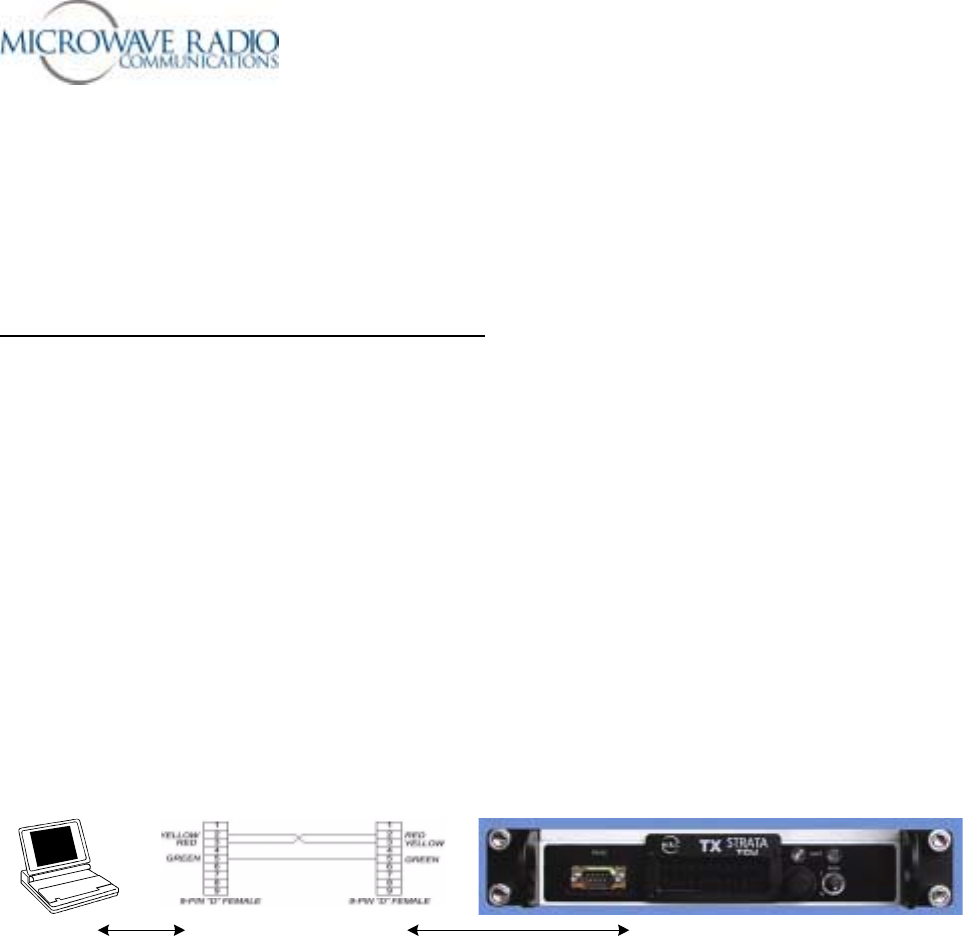
Preparations
The following preparations should be completed prior to attempting to configure the Strata TX radio
system using a serial data connection:
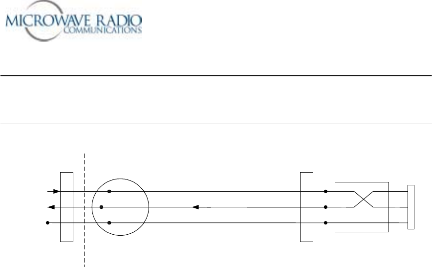
Establish serial data connections to and from the radio system. See the sketch below for details on how to
connect a PC to the Strata TX radio system.
PC Null Modem Connection Strata TCU or TXU
Figure 5 – Serial Data Connection Details
Notes:
• A serial data connection may be made to either a TCU or TXU pair so long as the TCU and the TXU
are inter-connected with a coaxial cable (enables system telemetry link and permits simplex powering
of adjacent units). Both units must be powered ON.
• Use a standard 9 pin RS-232 serial data “null” modem connection (DTE-to-DTE configuration)
between the PC and the radio unit(s) as shown in Figure 5. above. Recommended serial data cable
length not to exceed 50 feet.
• The system being configured should be interconnected as it will be used, i.e., all units inter-connected
properly with the appropriate RF termination connected to either the TXU or HPU RF output
connector. Note that some applications may use a TCU or TXU in a “stand-alone” mode.
Strata Operations Guide
- 14 -
TCU TXU HPU
!
NTSC
!
PAL
!
SDI
!
ASI
!
IF
RF OUT
RF/DC
Telemetry Telemetry
IF or Baseband Signal
DC Simplex Powering
IN
Dummy Load
12 v to 48 v
DC
RS-232
1.84 MHz OOK Tone
12 v to 48 v
DC
RS-232
Typical Strata System Configuration Setup
Strata TX Powering Options and Cautions
Note the following recommended Strata system powering options and rules.
1. TCU stand-alone powering: +12 volts to + 48 volts DC.
2. TXU stand-alone powering: +12 volts to + 48 volts DC.
3. TCU and TXU adjacent: +12 volts to + 48 volts DC. *
4. TCU separated from TXU/HPU (TXU supplying power): +48 volts DC (for distances > 100 feet). **
5. TCU separated from TXU/HPU (TCU supplying power): +24 volts (minimum). ***
Notes:
* When powering adjacent TCU/TXU configurations, apply power to both TCU and TXU units.
** Special rules apply for longer distance separation applications depending on coaxial cable type,
distance and whether an HPU is used.
*** Necessary to reduce current drain over IF coaxial cable – recommend +48 volts.

Strata Operations Guide
- 15 -
* * * CAUTION * * *
DC Voltages Present on Coaxial Cable
Center Conductors
Use Caution
For those Strata TX configurations that employ 2 or 3 modules, e.g., TCU + TXU
+ HPU, etc., the TCU and/or TXU may be used to power adjacent modules by
superimposing DC voltage on the interconnecting coaxial cable center conductor.
This feature is activated using the Strata TX front panel controls and remains in
effect until subsequently modified by the user. The voltages involved range from
+ 12 to + 48 volts DC (DC input voltage).
To avoid damaging radio and test equipment input circuitry, be certain you either
remove or isolate superimposed DC voltages from interconnecting coaxial cables
where necessary to protect externally connected equipment.
In the case of the TXU-to-HPU RF coaxial cable connection, the center conductor
will have DC voltages superimposed on the RF cable center conductor in order to
power the HPU. If the TXU RF output is connected directly to an antenna or test
equipment, be certain to disable the HPU On feature and therefore remove the DC
voltage superimposed on the TXU RF output.
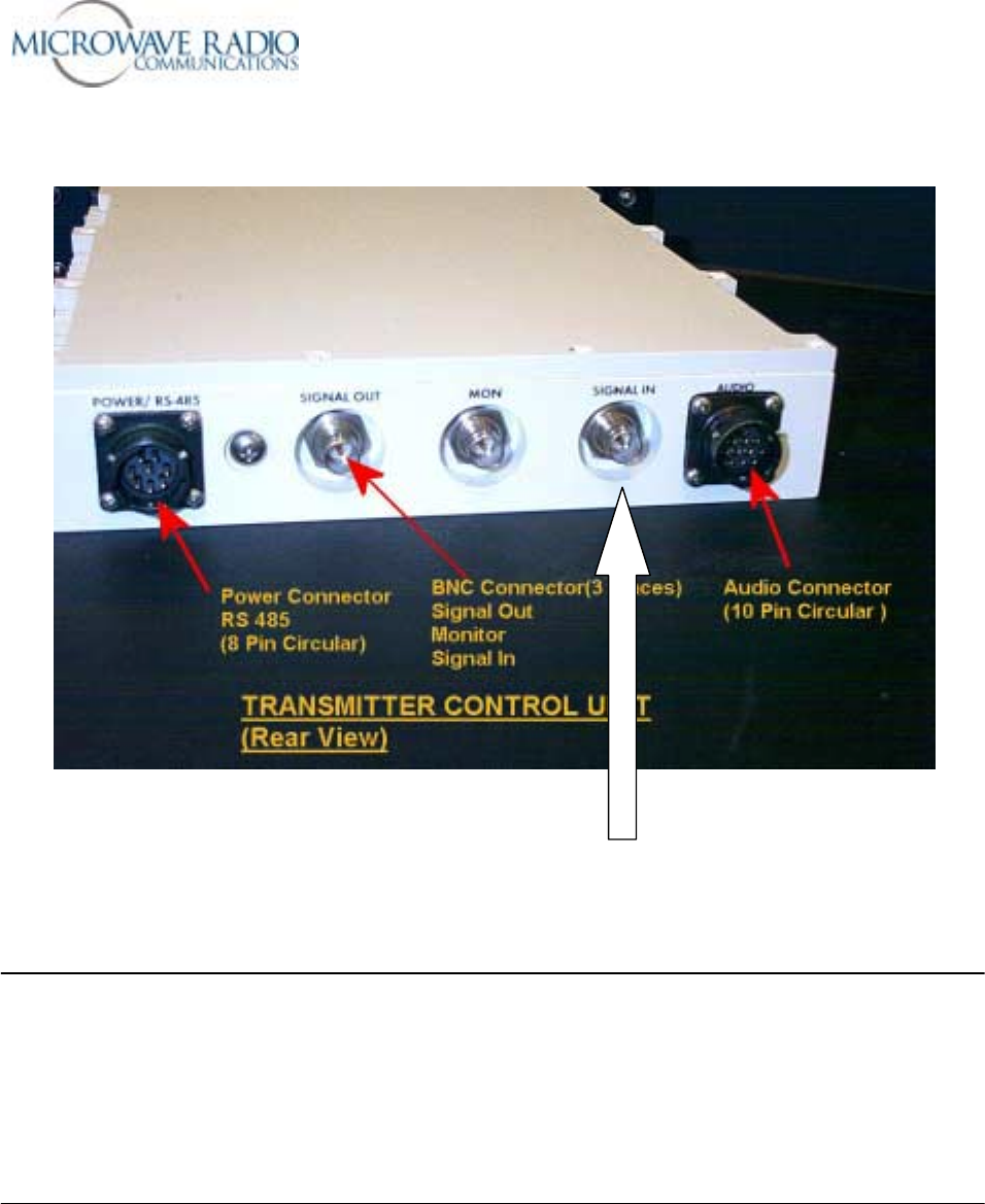
The Strata TCU “Signal In” BNC connector on the rear of the TCU module is
susceptible to damage if DC is present on the center conductor. Take care that the
TXU-to-TCU interconnecting coaxial cable (if used) is not inadvertently connected
to the “Signal In” connector instead of the “Signal Out” connector. Please see the
image on the following page for additional details.
Strata Operations Guide
- 16 -
TCU “Signal In” Connection – not DC isolated
Note:
To minimize the potential for damaging the TCU signal input circuitry, the “Signal Out” jack rear panel
BNC connector has been changed to a TNC type connector. Users are cautioned not to use a TNC-to-
BNC adapter on the TCU “Signal Out” jack to circumvent this protection feature. Each Strata TX system
that includes TXU and TCU modules is shipped with a short BNC-to-TNC coaxial cable assembly for
interconnecting TXU and TCU modules. For those system applications that require separating the TXU
and TCU over longer distances, users are advised to use a BNC “barrel” adapter on the BNC end of the
supplied coaxial cable assembly.
Strata Operations Guide
- 17 -
Step-by-Step Procedure
Use the following Strata configuration procedure when verifying or configuring the Strata TX system
using the Strata TX Configurator software over a local or remote serial data link.
1. Install the Strata Configurator software per instructions supplied with the software. This software is
designed to operate properly on Windows 32 bit operating systems, e.g., Windows 98/NT/2000/ or
XP operating systems.
2. Connect the PC serial port to the TCU or TXU per Figure 5. above. Apply the appropriate DC power
to the Strata TX radio system and operate the front panel power switch(s) to ON.
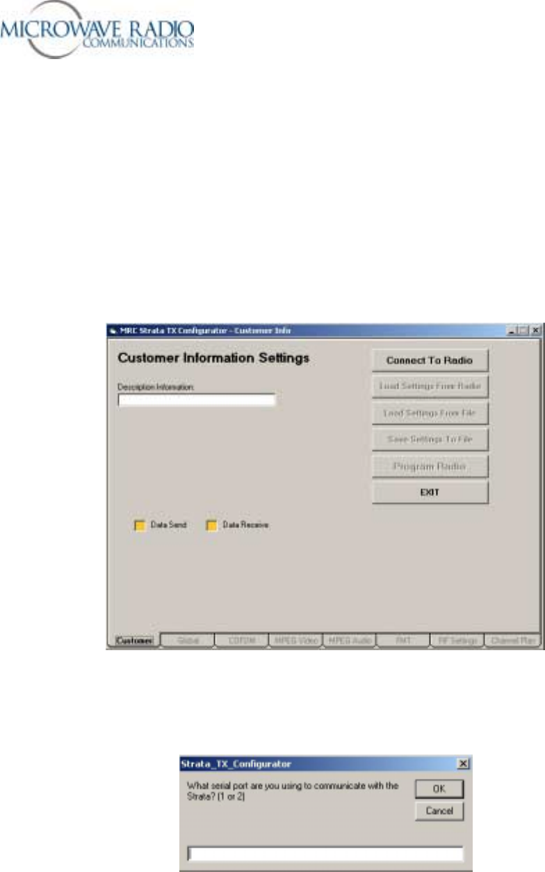
3. Start the Strata Configurator application. You should see the following main menu appear:
4. Click on the “Connect to Radio” control. The following dialog is presented.
Strata Operations Guide
- 18 -
5. Enter 1 or 2 depending on which PC serial data (RS-232) COM port is being used.
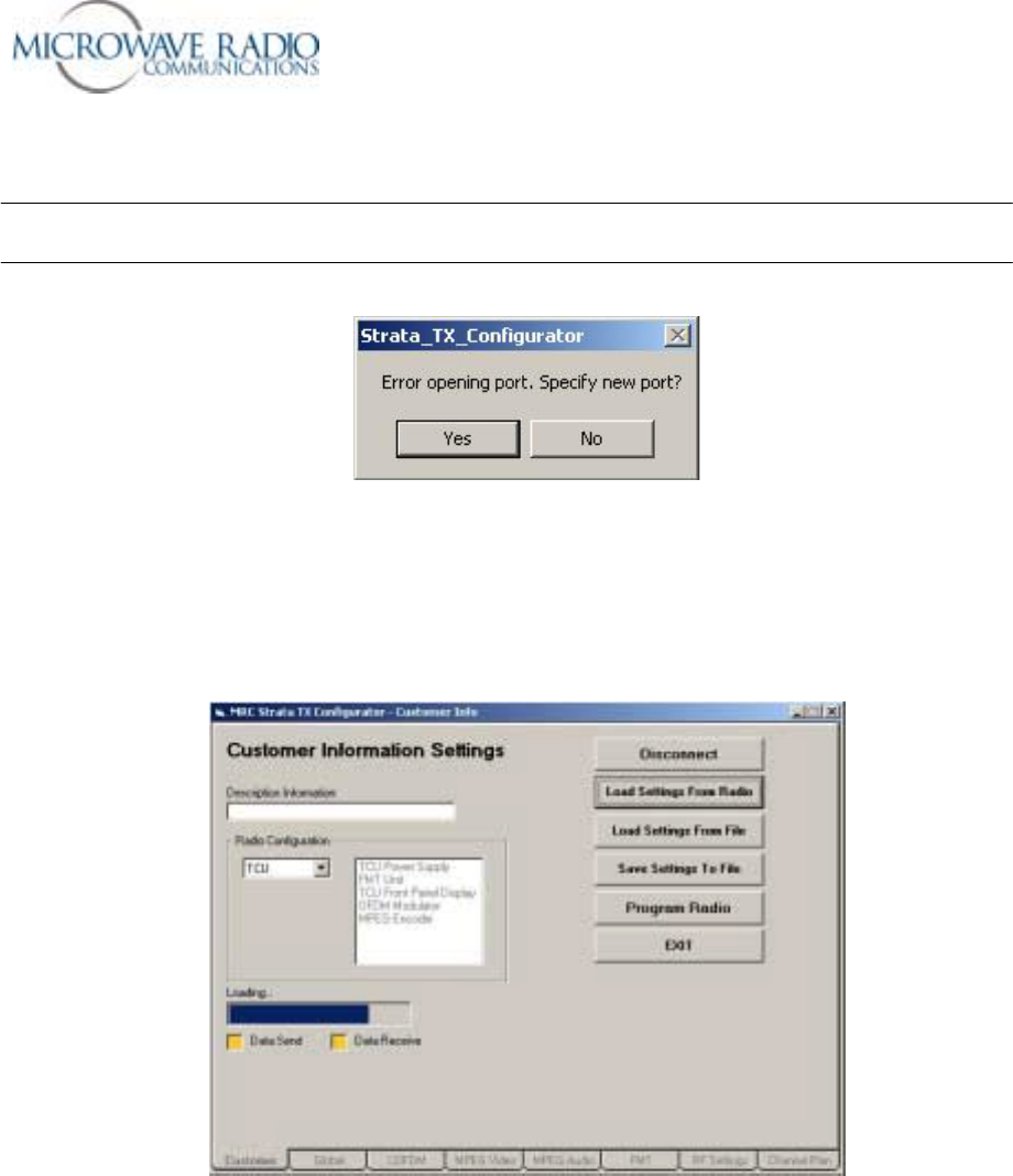
Note: If the Strata TX Configurator application is unable to open a valid serial data port or an invalid
number is entered, you will receive the following error dialog:
If you are unable to open a serial port or establish a valid serial port connection to a Strata TX radio
system, exit the application and attempt to determine the difficulty and try again.
6. Assuming a valid serial data connection is established with a Strata TX radio system, you should see
the main Customer screen display with all front panel controls activated as shown below.
7. Next use the “Load Settings From Radio” function to retrieve the current Strata TX radio
configuration. It is recommended you store this configuration to a file using the “Save Settings to
File” function especially when any modifications have been made to the current radio settings.
8. Access the Global, COFDM, MPEG Video, MPEG Audio, FMT and RF Settings menus by clicking
on the appropriate menu tabs. The channel frequency settings found in the “Channel Plan” tab are
only accessible for systems that do not include the “Frequencies Locked to Presets” option.
Strata Operations Guide
- 19 -
9. Select the correct configuration option or options for the intended application or applications. Please
note that some configuration options may not apply depending on specific hardware options supplied
and whether a unit being configured is connected to a companion unit, i.e., a TCU connected via a
coaxial cable to a companion TXU, etc.
10. Next, use the “Program Radio” function to load the specified changes and settings into the Strata
TX radio system. It is strongly recommended that you perform a “Load Settings From Radio”
action to verify the desired settings were loaded into the Strata TX radio system.
Note: An active programming or configuration retrieval session requires approximately 2 minutes to
complete. Do not disturb the radio system or serial data connections until an indication is received that
the current operation has completed.
11. When the Strata system has been properly configured and the front panel monitoring control has been
used to verify the desired configurations have been implemented, use the “Save Settings to File”
option and save the current system configurations for future use, either for restoring the current
system settings or for applying similar configuration parameters to another system. You may wish to
enter a descriptive name for this particular configuration in the Customer screen “Description
Information” field in addition to a unique file name to aid in identifying this particular system
configuration.
12. When the current Strata TX system configuration action has been completed, remove the serial data
connection to the Strata TX system.
13. Test and verify proper operation of the configured Strata system using the front panel controls as
described elsewhere in this document.
This completes remote configuration of the Strata TX system.
Note: A limited number of Strata system configuration parameters may be modified using the front panel
controls such as selecting pre-configured presets and powering adjacent units, etc. You may also
effectively use the front panel controls to monitor proper operation and review current preset
configurations, etc.
Basic System Operation
The following basic operational notes are supplied in an effort to ensure the Strata TX system is operating
properly.
1. Always ensure you apply the proper DC input power, including a verification of the current handling
capacity of the power source. Note that some applications require minimum DC power for proper
operation, e.g., the case where a TCU is separated from the TXU over a long length of coaxial cable.
2. Be sure the front panel controls are set properly to supply power to either or both a TCU or HPU unit
when DC power is supplied from the TXU. Note that the HPU obtains its DC operating power over
the RF coaxial cable from the companion TXU.

Strata Operations Guide
- 20 -
3. When initially powering a Strata TX system, the power/error front panel LED will indicate an error
condition (amber) for a few seconds prior to turning green. This is an indication that the Strata TX
components have not completed software initialization. You will also note this condition when
switching between digital and analog modes. Users will be prevented from operating the Strata
transmitter until the front panel power/error LEDs have turned green.
4. You should not attempt to change presets while the transmitter is active. Turn OFF the Strata
transmitter (hold front panel control knob in for 1 second) before changing presets. Before activating
the transmitter after changing a preset or operating frequency, use the front panel control to ensure the
selected operating frequency is the desired frequency.
5. Note that the front panel will not display the transmitter output power when an HPU is present. When
using a TXU without the HPU option, the approximate RF output power will displayed on the front
panel main menu display.
6. For those applications that require transmitting at lower output power, you may dial in additional IF
attenuation (1 to 31 dB) using the front panel control. Note that any additional attenuation applied in
this manner will be lost when changing presets or re-powering the system. For permanently installed
additional attenuation values associated with a system preset number, you may configure these values
using the supplied Strata TX Configurator utility. In this case the amount of additional attenuation
will apply when the associated preset is selected but may be temporarily changed using the front
panel control. Depending on the operating mode, and the characteristics of the radio components,
added IF attenuation may not decrease RF output power on a 1:1 basis. If accurate RF output power
setting is required, use an external RF power meter to ensure the desired amount of RF output power
is obtained.
7. For those systems configured for Frequency-locked-to-Presets, you may temporarily change the
transmitting frequency using the front panel control. Any channelized frequency entered in this
manner is temporary and will be lost when changing presets or re-powering the system. For those
systems configured for Frequency-unlocked-to-Presets, changing the current operating frequency
will remain in effect until changed by the user.
8. Note that Strata TX systems must be configured at the MRC factory for the following options:
• NTSC (default) or PAL composite video formats
• Frequencies-locked-to-Presets (Helicopter operation)
• Frequencies-not-locked-to-Presets (default option)
• RF band, e.g., 1.9 GHz to 2.5 GHz (default) or 2.3 GHz to 2.7 GHz
These options cannot be changed in the field.
9. Adjustment of FMT audio deviation levels cannot be accomplished in the field. There are no physical
controls permitting this adjustment. The FMT audio deviation levels are adjusted with special
software tools in the MRC factory for industry standard (+8 dBm input @ 75 kHz deviation) levels
unless otherwise specified.
Every effort has been made to supply a state-of-the-art and reliable Strata TX design. Should you
encounter any difficulty operating your Strata TX radio system, please contact Microwave Radio
Communications for assistance.
Strata Operations Guide
- 21 -
Appendix
External Connection Information
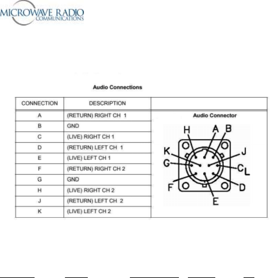
Note: The MRC P/N for the external circular panel audio connector cable assembly is 907471-1. This 3
foot long cable assembly includes the mating Amphenol connector and 4 each female XLR connectors.
For customers who wish to construct their own external audio connection cable assembly, the mating
Amphenol connector P/N is MS3116F12-10S.
MPEG Board Function Circular Connector Wire Color XLR
Analog Audio Input
J11- 1 (return) Right chan 1 A White #1 – pin 3
J11- 2 GND B Black #1 – pin 1
J11- 3 (live) Right chan 1 C Red #1 – pin 2
J11- 4 (return) Left chan 1 D White #2 – pin 3
J11- 5 GND B Black #2 – pin 1
J11- 6 (live) Left chan 1 E Red #2 – pin 2
Analog Audio Input
J12- 1 (return) Right chan 2 F White #3 – pin 3
J12- 2 GND G Black #3 – pin 1
J12- 3 (live) Right chan 2 H Red #3 – pin 2
J12- 4 (return) Left chan 2 J White #4 – pin 3
J12- 5 GND G Black #4 – pin 1
J12- 6 (live) Left chan 2 K Red #4 – pin 2

Strata Operations Guide
- 22 -
Digital Audio Input (AES-EBU) XLR
J13 - 1 – Chan 2+ #1 Pin 3
J13 - 2 – GND #1 Pin 1
J13 - 3 – Chan 2- #1 Pin 2
J13 - 4 – Chan 1+ #2 Pin 3
J13 - 5 – GND #2 Pin 1
J13 - 6 – Chan 1- #2 Pin 2
Total of 4 each audio circuits
Notes:
1. In the case of digital audio connections, note that the GND (ground) connection is common to two
audio circuits as opposed to the connections used for standard analog audio circuits. In the case of
digital audio circuits then, a single XLR connector supplies two (2) each audio circuits instead of a
single audio circuit in the case of standard analog audio connections.
2. Due to the variety of audio connection options available, either of two existing analog audio
connections may be connected to J13 (digital audio). The circular panel pin out will change
depending on which existing audio connection is used. See below for additional details.
Strata TX Digital and Analog Audio Options
Introduction
Due to the unique design of the Strata TX digital encoder circuit, a number of digital and analog audio
input options may be accommodated. This brief memorandum describes the provisioning and use of
these audio circuits.
Digital Encoder Audio Options
The current Strata TX system supports the following MPEG encoder audio input signals:
• Analog audio
• AES-EBU digital audio
• SDI Embedded digital audio
Note: SDI embedded digital audio is “embedded” within the SDI digital signal when the SDI video
option is employed, i.e., an SDI video + audio signal is connected to the TCU or TXU “Signal Input”
BNC connector. In this case the digital audio signals are not connected to the encoder via the circular
panel audio connector.

Strata Operations Guide
- 23 -
Analog Audio Options
Up to 4 individual analog audio input signals may be transported over the COFDM transport signal. This
accommodates the industry standard Channel 1 and Channel 2, Left and Right side audio circuits. Two
on-board 6 pin audio connectors are wired to the Strata TX circular panel audio connectors for connection
to customer supplied audio sources.
Note: Where an FMT is installed in a Strata TCU housing (digital + analog transmission), analog audio
input signals may be bridged to one or both FMT audio inputs in addition to being connected to the
MPEG encoder analog audio inputs. This option accommodates simultaneously distributing analog audio
input signals to both FMT (analog) and MPEG encoder (digital) modules. The current Strata TX design
handles impedance matching in the FMT module by terminating (FMT only) or bridging (FMT + MPEG
encoder) audio input signals connected to the FMT module.
Depending on whether one or two analog audio channels are required for analog and/or digital mode
operation, one or both audio input channels (two audio circuits per channel), all combinations of analog
audio only operation can be accommodated by distributing the audio input signals to either or both FMT
and MPEG encoder modules. See the sketch on the following page to view these options.
Strata Operations Guide
- 24 -
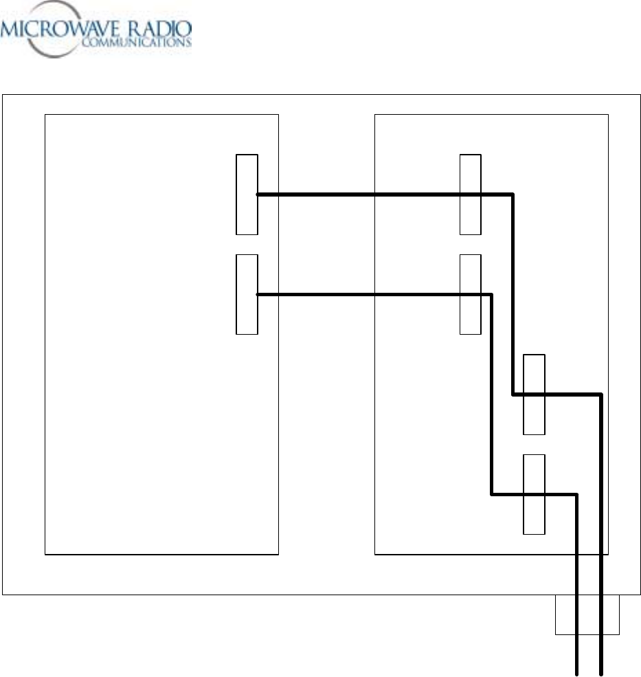
Bridging Connectors
Channel 1, 2
Audio Inputs
COFDM/MPEG Encoder
FMT
Chan 1
Audio
Chan 2
Audio
Connecting Analog Audio Input Signals to both FMT and MPEG Encoder Modules
Notes:
1. One or both analog audio input signals may be connected to an FMT module, an MPEG encoder
module, or both.
2. When connecting analog audio input signals to both FMT and MPEG encoder modules, the FMT
audio input circuit is optioned to “bridge” one or both audio channels to accommodate bridged
connections to a co-located MPEG encoder module.
3. Analog audio input signals may be split between FMT and MPEG encoder modules by directly
connecting one channel to each module.
Strata Operations Guide
- 25 -
4. Any combination of one or two analog audio inputs to either or both FMT or MPEG encoder audio
inputs is supported.
Digital Audio Options
The MPEG encoder digital audio on-board connector supports up to four each separate digital audio
inputs. Currently the AES-EBU digital audio format is supported.
Note: Since digital audio connections, unlike analog audio connections, share a common ground
connection between two audio circuits, digital audio wiring connections are able to accommodate twice
the number of audio circuits over the same number of connecting wires (leads). Please refer to the MPEG
encoder wiring pinout connections shown below for the differences between analog and digital wiring
connections.
MRC 907386-1 COFDM/MPEG Encoder PWB
Digital Audio
(J13)
Analog
Channel 1
(J11) Analog
Channel 2
(J12)
Strata Operations Guide
- 26 -
Analog Audio (Ch1) J11 1 – R-
2 – GND
3 – R+
4 – L-
5 – GND
6 – L+
Analog Audio (Ch2) J12 1 – R-
2 – GND
3 – R+
4 – L-
5 – GND
6 – L+
Digital Audio (Ch1 + Ch2) J13 1 – Ch2+
2 – GND
3 – Ch2-
4 – Ch1+
5 – GND
6 – Ch1-
Summary of Digital and Analog Audio Connection Options
As can be seen from the description above, a total of four each analog audio and four each digital audio
channels are supported. However, due to the limited number of pin connections on the circular panel
connector, use of digital audio requires audio connection wiring for one analog audio channel. Therefore,
whenever one of the circular panel audio connections is connected to the MPEG encoder digital audio
input, only one analog channel may be connected to either or both FMT and MPEG encoder modules.
The various audio connection options are summarized in the table below:
Analog Audio Digital Audio Number of Channels Option
X 2 FMT and/or MPEG
X 4 FMT and/or MPEG
X 4 MPEG only
X X 2 analog + 4 digital FMT and MPEG
Strata Operations Guide
- 27 -
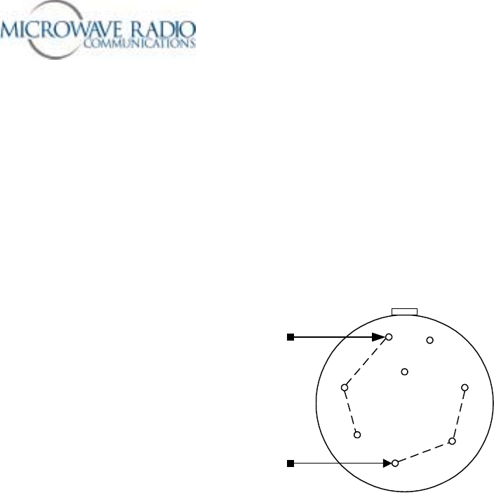
Strata Power Cables
TXU and TCU
These units use a KPT06F12-8S 8-pin female cable-mount power connector (MRC P/N = 52155-37). Pins
A, B and C are the Positive (+) voltage input connection. Pins D, E and F are the Negative (–) voltage
connection. The current drain for these units at 28 volts DC is approximately 1 ampere each. Please see
the power cable-connector pin-out sketch below for connection details.
A
B
C
D
E
F
G
H
+12 to +48 volts DC
Common (-) return
Strata TCU/TXU Power Cable Connector Pin-out (End View)
HPU
The HPU device is powered via the center conductor of the coaxial cable connection to the companion
TXU (early version). The current drain for this unit at 28 volts DC is approximately 3 amperes when the
transmitter is activated.
Strata Operations Guide
- 28 -
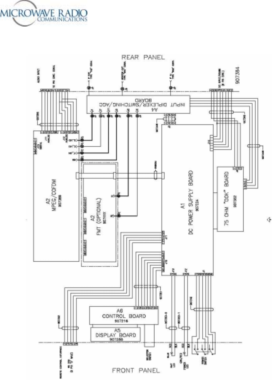
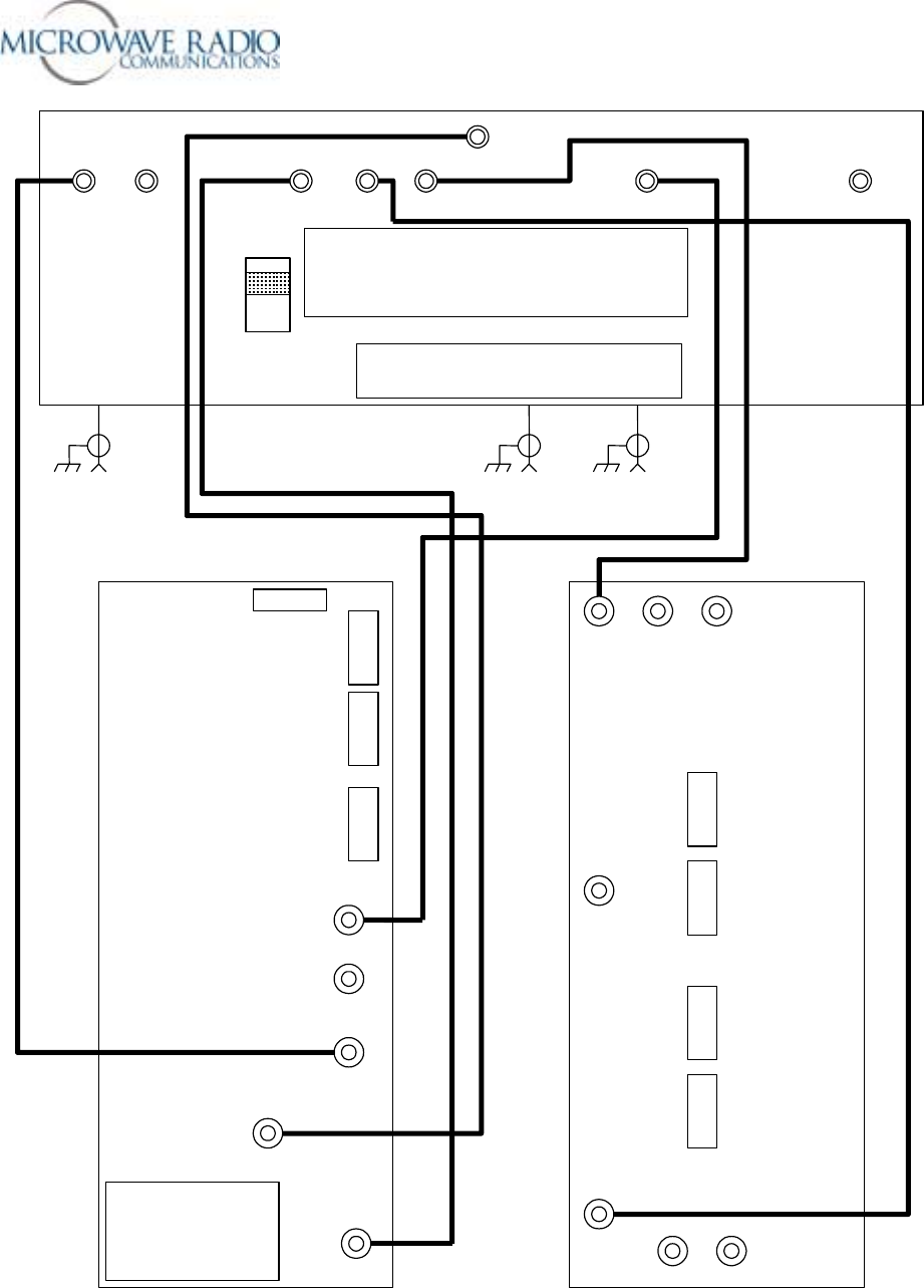
TCU Board Inter-connection Diagram
Strata Operations Guide
- 29 -
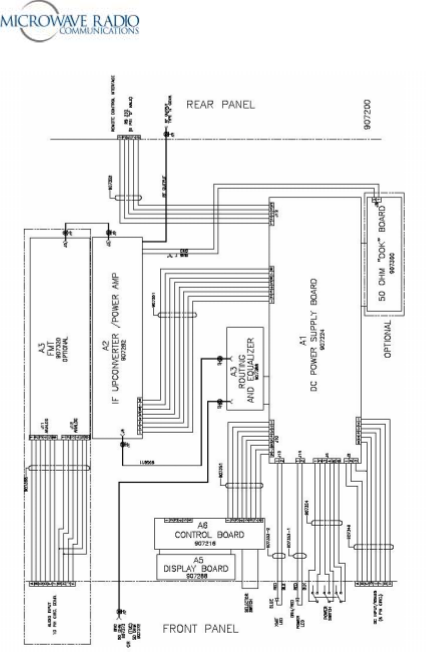
TXU Board Inter-connection Diagram
Strata Operations Guide
- 30 -
J1 J4 J7 J9 J6 J3 J10
FL1
Low Pass Filter
OUT
IN
SDIo
A
SIo MPEG CV FMT CV IF FMT J11
IF COFDM
FL1
OOK ASI
J5 J2 J8
COAX IN MONITOR COAX OUT
C_VID
IF_ON
D_VID
A
SI x 2
J13
J11
J12
J7
907386
COFDM/MPEG
Encoder
Digital Audio
Ch 1 Analog Audio
Ch 2 Analog Audio
RS-232 Data IF Out Audio 3 Audio 1
TP3
Video In
Audio 4 Audio 2
A
udio 3, 4
A
udio 1, 2
A
udio 1, 2
Audio 3, 4
907320 FMT
907346 Baseband Combine
r
TCU Video and IF Coaxial Cable Interconnection Details

Strata Operations Guide
- 31 -
Strata TX Front Panel Error Code List
Rotating the front panel TCU or TXU control knob allows access to displayed error codes whenever the
unit PWR LED color changes from green to amber. The list below references trouble conditions with
displayed error codes.
Error Codes MID
TXU IF FAULT E020
TXU RF FAULT E021
TXU PS 48 VOLT LINE E030
TXU PS 5.5 VOLT LINE E031
TXU PS 7 VOLT LINE E032
TXU PS 11 VOLT LINE E033
TXU PS TEMPERATURE E034
TXU PS IF COAX CURRENT E035
TXU PS IF COAX VOLTAGE E036
TXU PS IF COAX WATTAGE E037
TXU PS RF COAX CURRENT E038
TXU PS RF COAX VOLTAGE E039
TXU PS RF COAX WATTAGE EP3A
TXU PS CKT CURRENT EP3B
TXU PS CKT VOLTAGE E0EC
TXU PS CKT WATTAGE E03D
TXU PS DC BUS E03E
TCU PS 48 VOLT LINE E040
TCU PS 5.5 VOLT LINE E041
TCU PS TEMPERATURE E042
TCU PS COAX CURRENT E043
TCU PS COAX VOLTAGE E044
TCU PS COAX WATTAGE E045
TCU PS CKT CURRENT 3046
TCU PSCKT VOLTAGE E047
TCU PS CKT WATTAGE E048
TCU PS DC BUS E049
Strata Operations Guide
- 32 -
Note: While the above front panel error codes indicate that portion of the system most likely affected,
please contact MRC Technical Support for assistance should troubleshooting your Strata TX system
become necessary.
HPU PS 48 VOLT LINE E060
HPU PS 5.5 VOLT LINE E061
HPU PS 11 VOLT LINE E062
HPU PS TEMPERATURE E063
HPU PS COAX CURRENT E064
HPU PS COAX VOLT E065
HPU PS COAX WATTAGE E066
HPU PS CKT CURRENT E067
HPU PS CKT VOLTAGE E068
HPU PS CKT WATTAGE E069
HPU PS DC BUS E06A
COFDM ENCODER COMM ERROR E080
FMT VIDEO PLL UNLOCK E0E0
FMT AUDIO1 PLL UNLOCK E0E1
FMT AUDIO2 PLL UNLOCK E0E2
FMT AUDIO3 PLL UNLOCK E0E3
FMT AUDIO4 PLL UNLOCK E0E4
SYSTEM_ERROR_SUMMARY E400
Strata Operations Guide
- 33 -
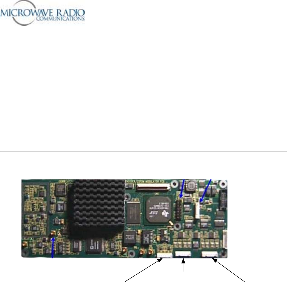
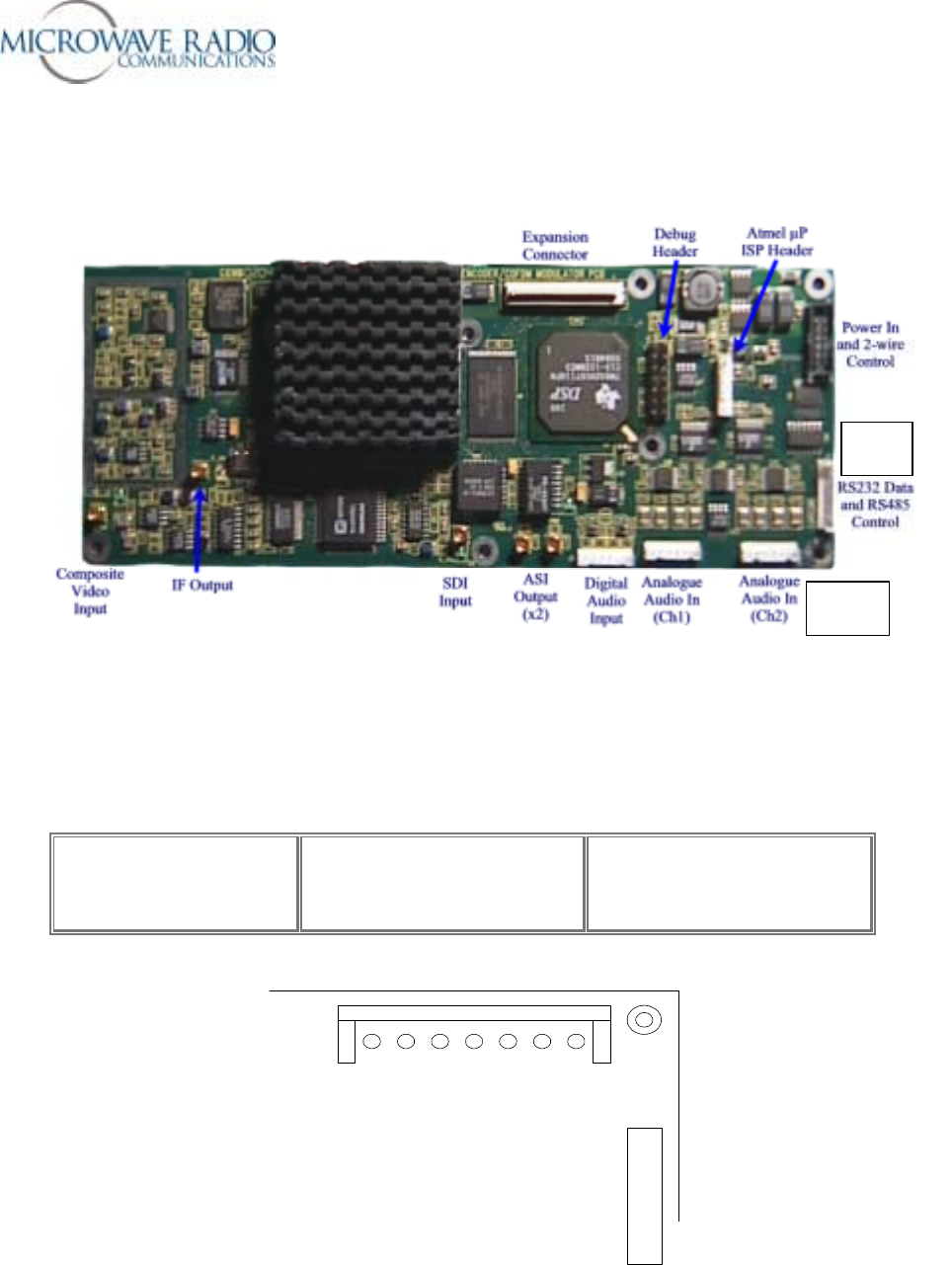
Strata Transmitter Wayside Data Channel Access
MRC 907386-1 COFDM/MPEG Encoder PWB Layout
J7
J12
Note:
For Wayside data channel access, use analog audio channel 2 cable assembly (J12). Audio pins F, G and
H in the audio circular panel connector (corresponding to J12 pins 1, 2 and 3) are connected to J7 pins 1,
2 and 3 per the pinout information shown below. Note that analog audio channel 2 Right Side
channel connections are removed and not available when the Wayside data channel option is
used.
Top View of 907386 COFDM/MPEG Encoder PWB
J7
J12
7 12 3
RS232 Wayside Data J7 1 – RS232TX (from encoder)
2 – RS232RX (to encoder)
3 – GND

Strata Operations Guide
- 34 -
Strata Operations Guide
- 35 -
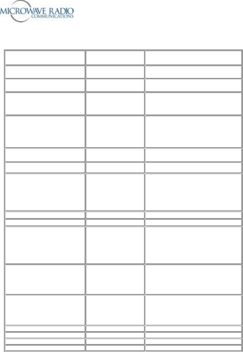
COFDM/MPEG Encoder PWB Connections
NAME PCB
DESIGNATION COMMENTS
Expansion Port Header
J1 Details available on request
DSP debug header
J2 Engineering Use Only
Power Connector and 2-wire control
interface J3 Pin 1 - TXD (from encoder)
Pin 2 - RXD (to encoder)
Pins 3,4,5,6 - GND
Pins 7,8,9,10 - +5.5V
ISP Connector for Atmel Processor
J4 Pin 1 - 5V
Pin 2 - SDOUT
Pin 3 - GND
Pin 4 - RESET
Pin 5 - SCLK
Pin 6 - SDIN
70MHz IF Output
J5 50 Ohm
Composite Video Input
J6 Terminated at 75 Ohm
RS232 Data and RS485 Control J7 1 – RS232TX (from encoder)
2 – RS232RX (to encoder)
3 – GND
4 – RS485 TX
5 – RS485 TX
6 – RS485 RX
7 – RS485 RX
SDI Input J8 75 Ohm
ASI out J9, J10 75 Ohm
Analog Audio (Ch1) J11 1 – R-
2 – GND
3 – R+
4 – L-
5 – GND
6 – L+
Analog Audio (Ch2) J12 1 – R-
2 – GND
3 – R+
4 – L-
5 – GND
6 – L+
Digital Audio (Ch1 + Ch2) J13 1 – Ch2+
2 – GND
3 – Ch2-
4 – Ch1+
5 – GND
6 – Ch1-
LED – Amber IF_ON Indicates IF Output is ON
LED – Green C_VID Indicates locked to input composite video
LED – Green D_VID Indicates locked to input SDI video
LED - Amber HLTH Heartbeat – flashing indicates software running
Strata Operations Guide
- 36 -
Note: The transmit data connection lead (TD) is used to support serial data flow control
communications between the encoder circuit and a connecting data terminal (PC). Most
applications do not use this capability.
1
2
3
J7 *
TD
RD
SG
Encoder PWB Circular Panel Audio
Connector
F
H
G
DB-9
DTE
3
2
5
Null Modem Cable
PC
DTE
3
2
5
Wayside Data Traffic
DB-9
* Note: J7 pin 1 is nearest to long edge of COFDM/MPEG PWB
End of Strata TX Operations Guide Document