Microwave Solutions MDU2000 MDU2000 X-Band Doppler Motion Detector User Manual August 11 2009
Microwave Solutions Ltd. MDU2000 X-Band Doppler Motion Detector August 11 2009
User Manual
MDU2000 User Manual_v5.doc Page 1
USER MANUAL
MDU2000
FCC-ID: ROO-MDU2000
IC: 10829A-MDU2000
Description
The Microwave Solutions MDU2000 Motion Detector Unit is an X-Band microwave transceiver
that utilises the Doppler shift phenomenon to "sense" motion. The unit, housed in a metal can,
features a dielectric resonator stabilised FET oscillator, which provides stable operation over a
broad temperature range in either CW or low duty cycle pulse mode and an integrated
homodyne receiver for enhanced sensitivity and reliability.
The basic principle of operation consists of detecting the frequency shift between a transmitted
and a received signal reflected back from a moving object within the field of view of the unit.
The unit produces a low level output signal which can be amplified and processed to provide an
audible or visual alarm signal. The MDU2000 employs low cost surface mount manufacturing
techniques which are field proven as being rugged and reliable.
Absolute Maximum Ratings
Parameter
Symbol
Rating
Units
Comment
Supply Voltage
VCC
+5.25
V
Operating Temperature
TOP
-20 to +70
°C
Performance level not guaranteed
Storage Temperature
TSTG
-40 to +80
°C
Electrical Characteristics
Parameter
Symbol
Min.
Typ.
Max.
Units
Comment
Transmit Frequency
fT
10.500
10.525
10.550
GHz
Pre-set during manufacture.
Temperature Stability
∆f
5
MHz
Over TOP range below
Output Power
POUT
10
dBm
EIRP
Antenna Gain
Ga
5
dBi
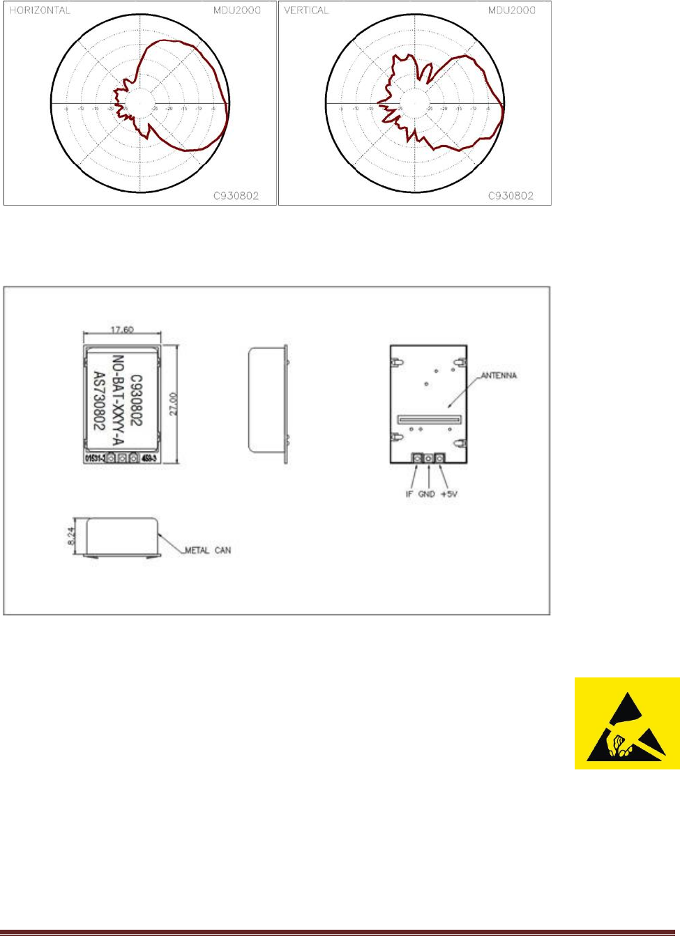
Antenna Beamwidth
50
°
-3dB, horizontal with tab down
60
°
-3dB, vertical with tab down
IF Output Offset
VDC
1.5
V
Into free space
Sensitivity
-84
dBm
10dB S/N ratio
Noise
10
µV
In 3Hz – 80Hz bandwidth
Supply Voltage
VCC
4.75
5.00
5.25
V
Supply Current
ICC
20
25
mA
Pulse Width
5
µs
Min. duty cycle – 1%
Operating Temp
TOP
-20
+55
°C
Full specification compliance
MDU2000 User Manual_v5.doc Page 2
Coverage Patterns
Connections & Mechanical Outline
Handling Precautions
The MDU2000 is sensitive to damage from ESD.
Normal precautions as usually applied to CMOS devices are sufficient when handling
the module.
Touching the connection points should be avoided before soldering the module into circuit.
Using a multimeter (e.g. for resistance measurement) between any of the connection
points may cause damage to the module.
Certification
Microwave Solutions Ltd. has established and maintains a Quality System that has been audited by BSI and holds ISO
9001:2008 approval under certificate FM56058.
The MDU2000 complies with the requirements of the RoHS Directive European Union Directive 2011/65/EU and with
the requirements of the REACH Regulations EC 1907/2006.

MDU2000 User Manual_v5.doc Page 3
OEM Responsibilities
Manufacturers of mobile or fixed devices incorporating MDU2000 modules are authorized to use the FCC Grants and
IC Certificates of the MDU2000 modules for their own final products under the conditions referenced in this
document. It is the responsibility of the manufacturer of the final product to ensure that the MDU2000 module is
operated within the approved conditions shown below. If the FCC/IC label of the module is not visible when the
module is installed inside the final product then the outside of the final product must also display a label stating
"Contains FCC ID: ROO-MDU2000" and "Contains IC: 10829A-MDU2000".
Approved Operating Conditions to meet FCC/IC requirements
The MDU2000 module can be operated in full compliance with FCC/IC requirements (depending on the characteristics
of the final product) under the following conditions:
1) The power supply voltage provided to the module (at the module terminals) must be maintained within the
specified range of +5 ± 0.25 volts under all conditions of AC line voltage irregularities, battery voltages,
ambient temperatures and worst case load conditions.
2) If the module is operated under pulsed conditions, the rise and fall times of the power pulse shall be less
than 1 µs and, during the pulse, the power supply voltage shall be maintained within the limits of 1) above
under all conditions.
3) A minimum separation distance of 1.7cm is required between the user and the module.
4) If the final product is designed for use in any situation except in motor vehicles or on aircraft the module can
be operated with any duty cycle up to and including 100% (averaged over 100ms).
5) If the final product is designed for use in motor vehicles or on aircraft, the module can be operated with a
maximum duty cycle of 100% (averaged over 100ms) as long as the final product includes features to prevent
continuous operation (as defined in the FCC Rules and Industry Canada Standards). A field disturbance
sensor will be considered not to be operating in a continuous mode if its operation is limited to specific
activities of limited duration (e.g., putting a vehicle into reverse gear, activating a turn signal, etc.).
FCC statement:
This device complies with Part 15 of the FCC Rules. Operation is subject to the following two conditions:
(1) This device may not cause harmful interference, and
(2) This device must accept any interference received, including interference that may cause undesired operation.
This equipment has been tested and found to comply with the limits for a Class B digital device, pursuant to Part
15 of the FCC Rules. These limits are designed to provide reasonable protection against harmful interference in a
residential installation. This equipment generates, uses and can radiate radio frequency energy and, if not
installed and used in accordance with the instructions, may cause harmful interference to radio communications.
However, there is no guarantee that interference will not occur in a particular installation. If this equipment does
cause harmful interference to radio or television reception, which can be determined by turning the equipment
off and on, the user is encouraged to try to correct the interference by one of the following measures:
- Reorient or relocate the receiving antenna.
- Increase the separation between the equipment and receiver.
- Connect the equipment into an outlet on a circuit different from that to which the receiver is connected.
- Consult the dealer or an experienced radio/TV technician for help.
This device may only be operated using the approved integral antenna.
This device must not be co-located or operating in conjunction with any other antenna or transmitter.
Changes or modifications not expressly approved by Microwave Solutions Ltd. may void the user's authority to
operate this equipment
In the event that these conditions or the Approved Operating Conditions above cannot be met, then the FCC and
Industry Canada certifications are no longer considered valid and the FCC ID and IC Certification Number cannot
be used on the final product. In these circumstances, the OEM integrator will be responsible for re-evaluating the
end product (including the transmitter) and obtaining a separate certification.

MDU2000 User Manual_v5.doc Page 4
Industry Canada statement:
This device complies with RSS-210 of the Industry Canada Rules. Operation is subject to the following two
conditions:
(1) This device may not cause harmful interference, and
(2) This device must accept any interference received, including interference that may cause undesired
operation.
Ce dispositif est conforme à la norme CNR-210 d'Industrie Canada applicable aux appareils radio exempts de
licence. Son fonctionnement est sujet aux deux conditions suivantes: (1) le dispositif ne doit pas produire de
brouillage préjudiciable, et (2) ce dispositif doit accepter tout brouillage reçu, y compris un brouillage
susceptible de provoquer un fonctionnement indésirable.