Midland Radio 70101BD VHF Transceiver User Manual FCC CARD
Midland Radio Corporation VHF Transceiver FCC CARD
users manual

1
SERVICE MANUAL
RF DATA LINK RADIOS
70-101BD
70-201BD
Important Information
2
All rights reserved. No part of this publication may be reproduced,
transmitted, transcribed, stored in a retrieval system, or translated into
any language without the written permission of Midland Radio
Corporation
No part of any copyrighted computer programs contained in the products
referred to in this manual may be copied or reproduced without the
express written consent of Midland Radio Corporation
Midland Radio Corporation reserves the right to change the products
described in this manual without prior notice.
© Midland Radio Corporation
This manual is designed to facilitate the set-up and service of the Midland 70-
101BD and 70-201BD RF Data Link Radio series. As necessary, service manual
supplements will be published and distributed on the following forms:
Manual Addition (MA)……………For supplemental information
useful in product service or
improvement. Printed on BLUE
paper.
Change Notice (CN)……………For details about changes made during
production by model and serial number.
Printed on YELLOW paper.
Manual Correction (MC).......For correcting literature errors not
related to production changes.
Printed on GREEN paper.
Technical Bulletin (TB)..........For solutions to field problems and
tips for performance improvement.
Printed on PINK paper.
3
Comments or suggestions concerning areas of manual improvement are
welcome.
4
TABLE OF CONTENTS
Manual Supplement Information.....................................................................ii
Table of Contents...........................................................................................iii
Acronyms and Abbreviations.........................................................................iv
GENERAL INFORMATION
Specifications ...................................................................................................1-3
PREPARATION
Test Equipment ................................................................................................4
Alignment Points...............................................................................................5
Complete Realignment......................................................................................6-7
CIRCUIT DESCRIPTION
Description.......................................................................................................8-11
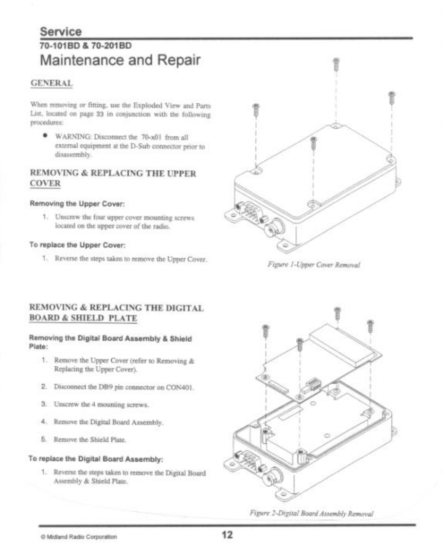
SERVICE
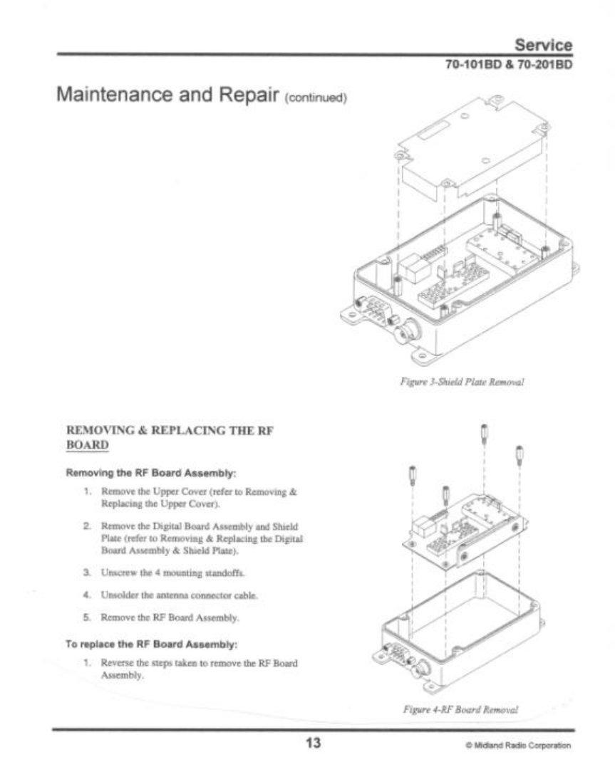
Maintenance and Repair ..................................................................................12-13
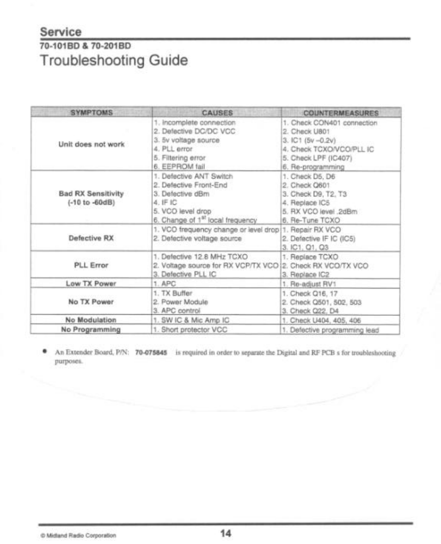
Trouble shooting guide......................................................................................14
Voltage Charts..................................................................................................15-18
Component Pinout ............................................................................................19-22
DIAGRAMS
Block Diagram..................................................................................................23
Wiring Diagram.................................................................................................24
TCXO Schematic..............................................................................................24
VCO (148-174MHz) Schematic..........................................................................25
VCO (440-470MHz) Schematic..........................................................................25
Front End (148-174MHz) Schematic ..................................................................26
Front End (440-470MHz) Schematic ..................................................................26
PA (148-174MHz) Schematic ............................................................................26
PA (440-470MHz) Schematic ............................................................................26
RF Board (148-174MHz) Schematic...................................................................27
RF Board (440-470MHz) Schematic...................................................................28
Digital Board Schematic....................................................................................29
RF Board View (148-174MHz) Layout ................................................................30
RF Board View (440-470MHz) Layout ................................................................31
Digital Board View Layout .................................................................................32
70-101/201BD Exploded View...........................................................................33
PARTS
70-101BD RF Board Parts List...........................................................................35-38
70-201BD RF Board Parts List...........................................................................39-42
Digital Board Parts List......................................................................................43-45
Replacement Parts Ordering .............................................................................46
5
ACRONYMS AND ABBREVIATIONS
Below is a list of common electrical abbreviations used in documentation.
CTCSS----------------------- Continuous Tone-Controlled Squelch
System
DCS(or CDCSS) ---------- Continuous Digital-Controlled Squelch
System
EEPROM ------------------ Electrically Erasable Programmable
Read Only Memory
MIL SPEC ------------------ Military Specification
RX --------------------------- Receive
TX --------------------------- Transmit
SINAD ---------------------- The ratio in decibels of signal + noise +
distortion to noise + distortion
VCO ------------------------ Voltage Controlled Oscillator
TCXO ---------------------- Temperature Controlled Crystal
Oscillator
PLL ------------------------- Phase Locked Loop
Installation and Setup Information for 70-101BD and 70-201BD Data Link Radios.
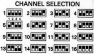
Transmit/Receive channels are chosen from the frequencies programmed by switches
inside the cover. Refer to the channel data list and set DIP switches for the desired
frequency.
6
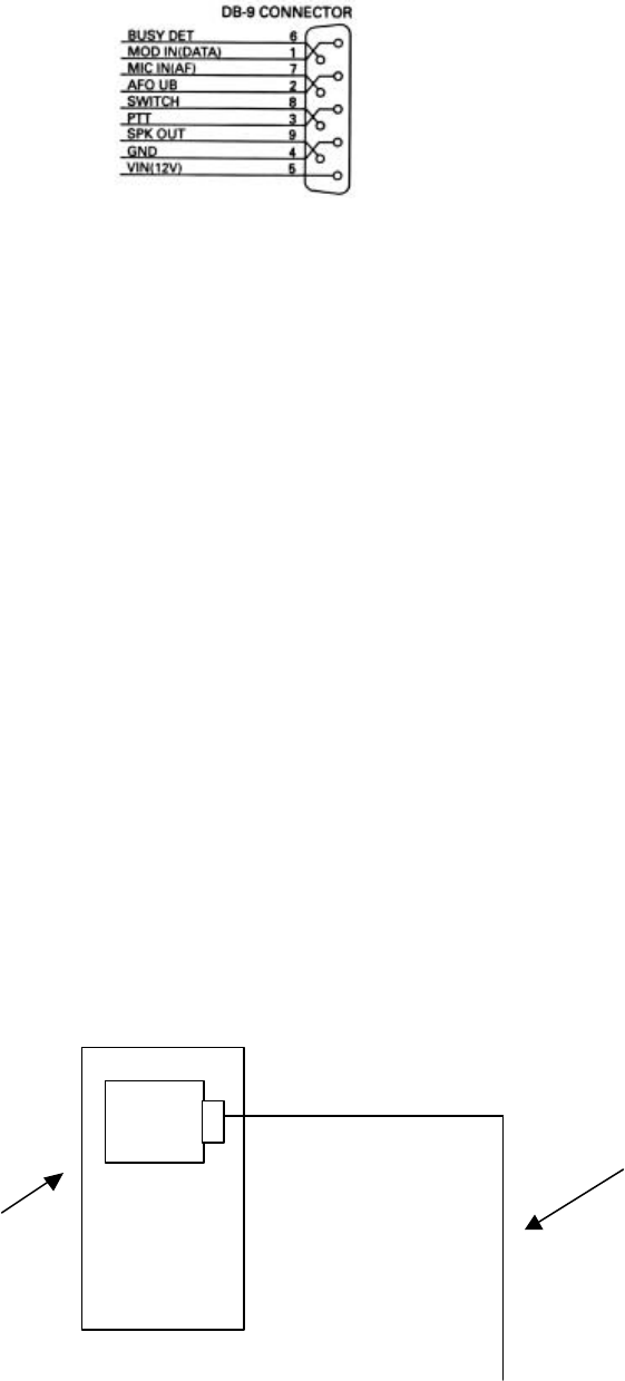
All connections to the unit are made through the DB9 connector. Connect wiring
according to the diagram below.
Connections to DB-9 connector:
1. Mod in (data). Audio sensitivity is 100mV RMS @ 60% Peak deviation.
2. AF out (data) (0.25 volt rms)
3. PTT . Ground to transmit.
4. GND
5. V in . 9-18 VDC
6. Busy Detector 0 volts DC = busy, 5 volts DC = open
7. Audio/Mic in. Sensitivity 5 mV. Typ.
8. Switch
9. Spkr out. 1 V. rms. typ. to 8 ohm load.
PS current:
Power save 15-30 mA. typ.
Standby 30-50 mA. typ.
Receive 35-60 mA. typ.
Transmit Low power 400-650 mA. typ.
Transmit High power 1100-1800 mA. typ.
How to Program 70-x01BD.
Requirement : PC running DOS or Windows 95/98, 70-1410K kit including:
Programing box, Programming Cable, and Software on one 3.5 disc.
(Optional: dot matrix printer)
Connection Diagram
Programming
cable
Com
port
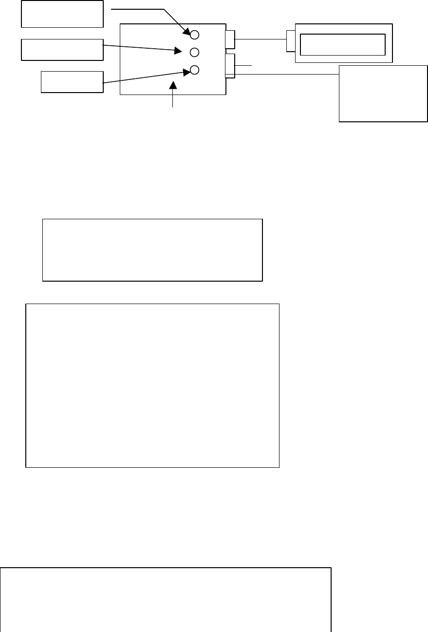
7
PC
Programming box
1. Install ACC900 by copying ACC900.exe to your PC or running it from the floppy
disk.
2. Connect the 70-x01 Unit through the Programming box and cable to the PC .(See
Connection Diagram)
3. Run Acc900.exe and select Band, 70-101BD VHF or 70-201BD UHF.
4. After selecting Band, Press Enter. The screen will show
5. On first operation you will need to set the Com Port and path to data files before
beginning to program radios.
6. To read radio channel data from a unit, first push box switch ON (DOWN).
Second you must select read radio from the software then Push Switch READ and
wait for the download to complete. If everything is OK Red LED will show while
reading. The screen will show:
70-x01BD
SUPPLY 12 V
DC
ON/OFF
WRITE
READ
Radio Model
70-101BD VHF
70-201BD UHF
Setup & Select Data Source
1. Select Comunication Port
2. Read Radio
3. Set Path to Data Files
4. Read Existing File
5. Restore Last File
6. Create New File
7. Delete a File
8. Exit
Programming Radio
Xxxxxxxxxxxxxxxxxxxxxxxxxxxxxxxxxxxxxx
Xxxxxxxxxxxxxxxxxxxxxxxxxxxxxxxxxxxxxx
Programming : Reading Word xx

8
Numbers following “Reading Word” will roll until the read is complete. The LED will turn
off, the screen will prompt that programming is complete,
and the channel list will display. (In some cases * this
box will be blank.)
7. You can change the channel data two ways. You can create a new frequency file
by selecting Create New file from Setup & Select Data source menu or by reading
from the unit and modifying the frequency that you want. To upload the changes
verify that power switch is still Down (ON). Press Right Arrow Key to select
Features Window and select 4. Program/Print/Save. The next Window is as below
Select Program Radio and push Write Switch. The Red LED will light followed
by the display of the screen as below
The numbers following “Writing Word” will roll until LED is off and programming is
complete. (In some cases * this box will be blank.)
Notes:
* in Windows 95/98 use ALT+ENTER to change to full screen display from window
display. Box contents will show.
Program/Print/Save
1. Program Radio
2. Program & Verify
3. Print Data
4. Save Data to Disk
5. Change Data
Programming Radio
Xxxxxxxxxxxxxxxxxxxxxxxxxxxxxxxxxxxxxx
Xxxxxxxxxxxxxxxxxxxxxxxxxxxxxxxxxxxxxx
Programming : WRITING Word xx
9
10
11

95.0
145.0
IMPORTANT NOTICE FCC LICENCE REQUIRED
The M222P operates on GMRS (Gerneral Mobile Radio Service) frequencies
which require an FCC (Federal Communications Commission) license.
Information on how to apply for a license is included in the owner's manual. A
user must be licensed prior to operating on channels 1 - 7 or 15 - 22, which
comprise the GMRS channels of the M222P. Serious penalties could result for
unlicensed use of GMRS channels, in violation of FCC rules, as stipulated in
the Communications Act's Sections 501 and 502 (amended).
Licensed users will be issued a call sign by the FCC which should be used for
station identification when operating the M222P. GMRS users should also
cooperate by engaging in permissible transmissions only, avoiding channel
interference with other GMRS users, and being prudent with the lenght of their
transmission time.
Questions regarding the license application should be directed to the FCC at
1-888-CALL FCC. Additional information is available on the FCC's website at
www.fcc.gov/wtb/prs/genmbl.html
Exposure To Radio Frequency Energy
Your Midland radio is designed to comply with the following national and
international standards and guidelines regarding exposure of human being to
radio frequency electromagnetic energy:
=
United Statse Federal Communications Commission, Code of Federal
Regulations: 47 CFR part 2 sub-part J
= American National Standards Indtitute (ANSI) / Institute of Electrical
and Electronic Engineers (IEEE) C95. 1-1992
= Institute of Electrical and Electronic Engineers (IEEE) C95.1-1999
Edition
= National Council on Radiation Protection and Measurements (NCRP)
of the Unitates, Report 86, 1986
= International Commission on Non-Ionizing Radiation Protection
(ICNIRP) 1998
To control your exposure and ensure compliance with the general population
or uncontrolled environment exposure limits, transmit no more than 50% of
the time. The radio generates measuable RF energy exposure only when
transmitting.
FCC Warning: For transmitter designed to operate above 25 MHz shall not be
certificated for use under this part if the operator can program and transmit on
frequencies, other than those programmed by the manufacturer, service or maintenance
personnel, using the equipment’s external operation controls.
The operator’s manual for this equipment states on page 7 under ‘installation and
programming’ that the equipment supplier or qualified radio tradesman using the Titan
Base Repeater programming software are the only ones that can change the transmitting
frequencies.