Midland Radio 701545B UHF TRANSCEIVER User Manual USERS MANUAL 2
Midland Radio Corporation UHF TRANSCEIVER USERS MANUAL 2
UserManual.wiki
>
Midland Radio
>
701545B User Manual
>
USERS MANUAL 2
Contents
1.
USERS MANUAL 1
2.
USERS MANUAL 2
USERS MANUAL 2
Navigation menu
Upload a User Manual
Namespaces
Wiki Guide
HTML
PDF
Info
Views
User Manual
Discussion / Help
Navigation

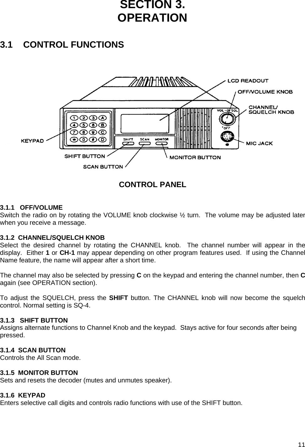
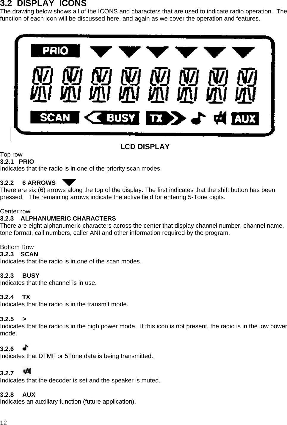
![9 SECTION 2. INSTALLATION 2.1 RADIO INSTALLATION Note: It is highly recommended that a qualified technician or engineer perform installation. Special equipment is required to properly install and tune the antenna. 2.1.1 LOCATION The recommended location is under the dash or near the console area within reach of the operator. Do not mount the radio near heat vents or where it will be exposed to direct sunlight. Leave space behind the radio for proper ventilation and for access to the connectors and cables at the rear of the radio. Note that the bracket is designed to permit mounting on surfaces above or below the radio. 2.1.2 TRANSCEIVER INSTALLATION [Tag # from drawing above] Mount the radio as follows: 1. Use the mounting bracket, tag # 6, to mark the location of the mounting holes. 2. Drill four 3mm (1/8”) holes for the mounting screws. 3. Attach the bracket using 4 black self-tapping screws and flat washers, tag # 7 & 8. Make certain that the release tabs are facing forward. 4. Slide the radio into the bracket, aligning the slots on each side. Press in until it snaps into place. 2.1.3 BATTERY CABLE INSTALLATION The KG208 operates from a 12 V negative ground vehicle system. 1. For 12 V positive ground systems, use an Astron 1212 polarity converter. 2. For 20 - 50 V negative ground systems use a NewMar model 32-12-10 converter. 3. For 20 - 56 V negative, positive or floating systems, use NewMar model 48-12-12-I isolated converter. 4. Install the cable into the vehicle. The cable terminals should be placed near the battery or converter. The white connector should be near the radio. 5. Avoid hot parts in the engine compartment. 6. Tie cable to the vehicle body at several points to avoid movement. 7. Use rubber grommets or tape when passing through holes in the chassis. 8. Connect blue lead to the or the negative terminal of the battery or converter. 9. Connect the red lead to the positive terminal of the battery or converter. 10. Connect the white connector to the matching connector on the radio cable. 11. Do not turn on the radio until installation is complete. 2.1.4 MICROPHONE INSTALLATION It is very important that the microphone be installed in a convenient location to avoid distracting the driver when he wants to use it. Select a location near the radio to avoid stretching the microphone cable. 1. Connect the microphone to the radio. 2. Using the hang-up clip, mark the location for the three mounting holes. 3. Drill three 2.5 mm (3/32”) holes. Be very careful that you do not drill into wires or other components. 4. Mount the hang-up clip using three self-tapping screws and flat washers. 5. Hang the microphone on the clip. 2.1.5 OPTIONAL EXTERNAL SPEAKER INSTALLATION The external speaker is highly recommended for noisy vehicles or where multiple radios are in use. It provides an increase in power over the internal speaker and it may be positioned to provide better clarity for the operator. 1. Remove the two large mounting knobs and remove the speaker from the mounting bracket. 2. Use the mounting bracket to mark the location of the mounting holes. 3. Drill two 3 mm (1/8”) holes.](https://usermanual.wiki/Midland-Radio/701545B.USERS-MANUAL-2/User-Guide-687763-Page-9.png)